


Languages
Pages
Legal


GE Fanuc Automation
Computer Numerical Control Products
Series 0 / 00 / 0-Mate
Operation and Maintenance Manual
GFZ-61397E/02 June 1996

1. CRT/MDI PANEL
1
1.1 Standard CRT/MDI Panel
M series
Soft key (Option)
9″ CRT
1.2 Full Key CRT/MDI Panel
M series
ON
OFF
POWER
Soft key
9″ CRT

3
1
4
5
6
7
8
9
10
2
2
Page change keys
Program edit keys
Input key
Output/Start keyFunction keys
Cursor move keys
Data input keysReset button
Page change keys
Program editkeys
Input key
Output/Start keyFunction keys
Cursor move keys
Data input keysReset key
Shift key

1. CRT/MDI PANEL
3
1.3 CRT/MDI with MMC
POWER
I+OFF O+OFF

3
1
4
5
6
7
8
9
10
2
4
AUXGRAPH
MMC/CNC
SHIFTRESETOUTPUTSTART
/
.
A
.
B
.
C
.
D
$
E
%
F
&
G
.
H I J K
L M N
SP
O
>
P
.
Q
–
R
<
S
>
T
[
U
]
V
.{
W
}
X
:
Y
;
Z
.
EOB
7 8 9 ALTER
4
.
5 6 INSRT
1 2 3
.
DELET
–
:.
0
.
.
.
INPUT
POS PRGRM CAN
DGNOSPARAM
OPRALARM
FUNC
MENUOFSET
MMC/CNC change key
Shift keyReset key
Start/output key
Program edit keys
Function keys
Input key

1. CRT/MDI PANEL
5
1.4 MDI Keyboard
� Standard MDI keyboards (T series)
� Full MDI keyboards (T series)

3
1
4
5
6
7
8
9
10
2
6
� Standard MDI keyboards (M series)
� Full MDI keyboards (M series)

1. CRT/MDI PANEL
7
� Full MDI keyboards (14″ CRT for M series)

3
1
4
5
6
7
8
9
10
2
8
� MDI keyboards with MMC

1. CRT/MDI PANEL
9
1.5 Explanation of the Keyboard
Number Name Explanation
1 Power ON and OFF buttons
� OFF | ON
Press these buttons to turn CNC powerON and OFF.
2 RESET key
RESET
Press this key to reset the CNC, to can-cel an alarm, etc.
3 START key
OUTPTSTART
This key is used to start MDI operationor automatic operation, depending onthe machine. Refer to the manual pro-vided by the machine tool builder. Thiskey is also used to output data to an in-put/output device.
4 Soft keys (option) The soft keys have various functions,according to the applications. The softkey functions are displayed at the bot-tom of the CRT screen.
Soft key of left edge :
Return menu key
Soft key of right edge :
Continuous menu key
5 Address and numeric keys
(N 4 …
Press these keys to input alphabetic,numeric, and other characters.
6 SHIFT key
SHIFT
SHIFT key
(Full MDI keyboard)
Some keys have two characters ontheir keytop. Pressing the <SHIFT>key switches the characters. Specialcharacter � is displayed on the screenwhen a character indicated at the bot-tom right corner on the keytop can beentered.
7 INPUT key
INPUT
When an address or a numerical key ispressed, the data is input to the buffer,and it is displayed on the CRT screen.To copy the data in the key input bufferto the offset register, etc., press the
key.
This key is also used to input data froman input/output device.
INPUT

3
1
4
5
6
7
8
9
10
2
10
Number ExplanationName
8 Cancel key
CAN
Press this key to delete the input dataor the last character in the key inputbuffer.
9 Program edit keys
ALTER INSRT DELET
Press these keys when editing the pro-gram.
: Alteration
: Insertion
: Deletion
ALTER
DELET
INSRT
10 Function keys
…POS PRGRM
Press these keys to switch displayscreens for each function.
11 Cursor move keys
CURSOR
There are two different cursor movekeys.
: This key is used to move
the cursor in an upward or
reverse direction.
: This key is used to move
the cursor in a downward
or forward direction.
12 Page change keys
PAGE
Two kinds of page change keys areavailable.
: This key is used to
changeover the page on
the CRT screen in the re-
verse direction.
: This key is used to
changeover the page on
the CRT screen in the for-
ward direction.
13 MMC/CNC change key
MMC/CNC
Selects whether the MMC screen orCNC screen is displayed on the CRT.

1. CRT/MDI PANEL
11
1.6 Key Input
� For standard MDI keyboard
On the standard MDI keyboard, the same key is used to input both anaddress and a numeric value. When “ADRS.” is displayed on the top of the key input buffer, addresses canbe input. When “NUM.” is displayed on the top of the key input buffer, numeric valuescan be input.
[ ][ ]
[ ][ ]
4
X
[ ][ ]
[ ][ ]
4
X
ADRS.
NUM. X
NUM. X
NUM. X 4
Press key Press key
The following keys are used for inputting multiple addresses. They may benot displayed on the screen depending on the options used.
T series
CA
C A B
KIH I K Y
JQP J Q P
NO.V
B
D
H
V L
Y
M series
NO.
4thB D B 4th
KJI I J K
LPQ P Q L
D

3
1
4
5
6
7
8
9
10
2
12
� For full MDI keyboard
A “<” is displayed at the end of the key input buffer indicating the inputposition of the next character.
Key inputbuffer display
[ ] [ ] [ ] [ ] [ ]
N001X100Z<
Key input buffer display
To input the symbol indicated at the lower part of a key top, press the SHIFT
key to change the prompt < to �. Then press the key.

2. CRT/MDI OPERATION
13
2.1 Screen Transition Triggered by the Each Func-
tion Key
POS
Screen transition triggered by thefunction key
POSPOSITION DISPLAYSCREEN
Current position screen
Position displayof absolute coor-dinate system
Display of runtime and partscount
Display ofactual speed
Position displaysof relative coordi-nate system
Total positiondisplay of eachcoordinatesystem
Manual handleinterruption
ABS REL ALL HNDL
Display ofactual speed
Display ofactual speed
Setting of rela-tive coordinatevalues
Display of distance to go
Display ofactual speed
Display of runtime and partscount
Display of runtime and partscount
Display of runtime and partscount
Display of distance to go

3
1
4
5
6
7
8
9
10
2
14
*2
Display of pro-gram contents
Display of pro-gram numberand sequencenumber
������ ��������� �������� ����� �������� ����� ��� ��� �� ��� �� �
Program screen
Display of cur-rent block andmodal data
PRGRM CHECKCURRNT NEXT
PRGRM
AUTO (MDI)*1
Display of cur-rent block andnext block
Program beingexecutedAbsolute / relative coordinate valueDistance to goModal values
FL.SDL
Command for MDI opera-tion
[SCHDUL]
Setting ofschedule
Program screen
PRGRM
(MDI)*1RSTR
Program restart
*1
*2
AUTO
BG–EDT
Back groundeditingscreen
Displayed in MDI modeNot displayed in MDI mode
PROGRAM SCREEN
*1

2. CRT/MDI OPERATION
15
PROGRAM SCREEN
Program edit-ing screen
Display of pro-gram directoryon CNCmemory
PRGRM LIB C.A.P.EDIT
Conversational programming screen
EDIT
Back groundediting screen
Program screen
����� ���������� ��� ��� ����� ������� ����� ��� ���� ���
Program screen
PRGRM
PRGRM
FLOPPYI/O
Display of pro-gram directoryon floppy cas-sette
BG–EDT EX–EDT
Extended partprogram editing
*1
*1
*2
*1
*2
Displayed if the Floppy Cassette is specified as the input/output unit
Displayed if the above conditions are not satisfied
Condense ofCNC memory

3
1
4
5
6
7
8
9
10
2
16
Setting of the addi-tional workpiecezero point offsetvalue
Setting of work-piece zero pointoffset value
Tool offset value
Display of tooloffset value
OFFSET
Screen transition triggered bythe function key (M series)
OFFSET SCREEN
Display of custom macrovariables
Setting of tooloffset value
Setting of pat-tern data
Tool lengthmeasurement
Tool offset value
Display of pat-tern menu
MENU
OFSET
MENUOFSET
MACRO MENU TOOLLFWORK
Display of work-piece zero pointoffset value
Display of toollife manage-ment data
Setting of macrovariables
Preset of toollife counter
WORK48
Display of the addi-tional workpiecezero point offsetvalue

2. CRT/MDI OPERATION
17
Set macro vari-ables
Tool offset value
Display toolwear offsetvalue
WEAROFFSET
Screen transition triggered bythe function key (T series)
OFFSET SCREEN
Display toolgeometry off-set value
Set tool wearoffset value
Set work shiftor workpiecezero point off-set value
Tool lengthmeasurement
Tool offset value
Display workshift or work-piece zero pointoffset value
MENU
OFSET
MENUOFSET
GEOM W.SHFTWORK
MACRO
Display macrovariables
Display toollife manage-ment data
Set tool geome-try offset value
Preset tool lifemanagementdata
Display Y–axistool wear off-set value
Set Y–axis toolwear offsetvalue
Set Y–axis toolgeometry off-set value
Display Y–axistool geometryoffset value
TOOLLF WEAR GEOM

3
1
4
5
6
7
8
9
10
2
18
Setting of se-quence numbercomparison andstop
����� ��� ����� ������� ���� �� ���� ���
Setting of pitch error compensa-tion data
Parameter screen
PARAM DGNOS
PARAMETER/DIAG-NOSTIC SCREEN
Display of pa-rameterscreen
Setting of param-eter
Display ofdiagnosisscreen
DGNOS
PARAM
DGNOS
PARAM
SV–PRM
Display ofservo settingscreen
*
Display ofservo tuningscreen
Display ofsetting data
Setting of set-ting data
* The servo setting/tuning screen can be suppressed if bit 0 ofparameter 0389 is specified accordingly.
Setting of partscount
Display of run time, parts count
Display of dateand clock
Setting of dateand clock

2. CRT/MDI OPERATION
19
Screen transition triggeredby the function key
OPRALARM
OPR
Display ofalarm screen
ALARM
Display of soft-ware operator’spanel generalpurpose switch
ALARM SCREEN
Alarm screen
ALARM OPR MSG
Display of oper-ator’s message
Setting of soft-ware operator’s panelgeneral purposeswitch

3
1
4
5
6
7
8
9
10
2
20
2.2 CRT/MDI Operation
Command display
� Function button PRGRM
During the AUTO mode, press (page) or the corresponding soft
key to cause any of the following four types of displays to appear.
(1) A program being currently executed is displayed.
PAGE
PAGE
The cursor is set to the beginning of the programbeing executed.
(2) The command currently being executed and themodal values specified before are displayed.
PAGE (3) The command currently being executed and thenext command to be executed are displayed.
(4) Program check
The block currently being executed, the currentposition, and the modal values specified beforeare displayed.
PAGE
PROGRAM O2000 N0130O2000 ;N100 G92 X0 Y0 Z50. ;N110 G91 G00 Y50. ;N120 Z–50. ;N130 G41 G17 H1 G01 X20. F3000 ;N140 G02 J–25.5 ;N150 X20. ;N160 G02 X12.5 Y12.5 R12.5 ;N170 G01 Y40. ;N180 X30. Y30. ;N190 G40 X50. ;
S 0 T 16:59:40 BUF AUTO [ PRGRM ] [CURRNT] [ NEXT ] [ CHECK ] [ RSTR ]
(CURRNT) (MODAL)X 20.000 G67 G01 F 3000
G01 F 3000 G54 G17 RG17 H 1 G64 G91 P
G69 G22 QG15 G94 HG25 G21 M
G41 SG41 G49 T
G80G80 G98 S
G50S 0 T0000
02:50:52 BUF AUTO[ PRGRM ] [ CURRNT ] [ NEXT ] [ CHECK ] [ RSTR ]
PROGRAM O2000 N00130
X 20.000 J –25.500G01 F 3000 G02G17 H 1
(CURRNT) (NEXT)
S 0 T02:52:14 BUF AUTO[ PRGRM ] [ CURRNT ] [ NEXT ] [ CHECK ] [ RSTR ]
PROGRAM O2000 N0130
G41
G80 G80
N130 G41 G17 H1 G01 X20. F3000 ;N140 G02 J–25.5 ;N150 X20.0 ;N160 G02 X12.5 Y12.5 R12.5 ; (RELATIVE) (DIST TO GO) ( G) X 17.600 X 2.400 G01 G21 G50 Y 50.000 Y 0.000 G17 G41 G67 Z 0.000 Z 0.000 G91 G49 G54
G22 G80 G64 G94 G98 G69
F 3000 P H 1 S R Q M T
ACT.F 3000 MM/M S 0 T02:53:16 BUF AUTO[ PRGRM ] [ CURRNT ] [ NEXT ] [ CHECK ] [ RSTR ]
PROGRAM CHECK O2000 N0130
PRGRM
* Besides the above displays, the program restart screen is displayed insome cases. (Option)

2. CRT/MDI OPERATION
21
Program display
� Function button PRGRM
During the EDIT mode, press the PRGRM key several times or the
corresponding soft key to cause either of the following two types ofdisplays to appear.
(1) The program is displayed.
The program and sequence numbers are displayed atthe upper right section of the screen.
(2) The amount of program memory in use isdisplayed.
PROGRMO0100 ;N10 G92 X0 Y0 Z0 ;N20 G00 Z10. Y–50. ;N30 G01 X200. Y–60. F500 T12 ;N40%
O0100 N0040
� Number of registered programs� Memory area in use� Program list
< S 0 T 10:39:27 EDIT[ PRGRM ] [ LIB ] [ FLOPPY ] [ ] [ C.A.P. ]
SYSTEM EDITION 0466 – 25 PROGRAM NO. USED : 14 FREE : 49 MEMORY AREA USED : 275 FREE : 3820PROGRAM LIBRARY LIST
O0010 O2000 O0020 O0030 O0200 O0300O0555 O1200 O0777 O1234 O0040 O0050O1969 O1224
> S 0 T03:04:17[ PRGRM ] [ CONDNS ] [ ] [ ] [ C.A.P. ]
PROGRAM O1224 N0000
PRGRM
PRGRM
* If the directory display of floppy cassette is provided, a file list, in additionto the above displays, appears on the screen.
Reset
Press the RESET . This key is usually used to reset the alarm.
When the RESET is pressed, the NC enters one of the states listed below.
Before a reset After a reset
A tool movement command contin-ues to be executed.
The tool decelerates and stops. The unex-ecuted amount of movement disappears.
An M, S, or T continues to be sentout.
A send–out sequence is terminated. Referto the machine tool builder’s manual for whatoccurs on the machine side.
When the buffer isl d d ith
MDI mode The contents of the buffer are not erased.loaded with oneblock
Other modes The contents of the buffer are erased. TheBUF display disappears.
In any case, pressing the RESET resets the NC. In a mode other than the MDI
mode, RESET causes the labels to be skipped.

3
1
4
5
6
7
8
9
10
2
22
Custom macro variable display/setting
� Function button MENUOFSET
Press the MENUOFSET key several times or the corresponding soft key to
select the desired screen.
VARIABLE O1234 N1234NO. DATA NO. DATA100 123.456 108101 0.000 109102 110103 111104 112105 113106 114107 115
ACTUAL POSITION (RELATIVE)X 0.000 Y 0.000Z 0.000 B 0.000
MDI [OFFSET ] [ MACRO ] [ MENU ] [ WORK ] [ ]
PAGE
If a variable is null, the corresponding valuefield is left blank. If the absolute value isgreater than 99999999, the correspondingvalue field contains ********.
CURSOR
Numeral
MENUOFSET
MENUOFSET
INPUT
Tool compensation value display/setting
No. Offset number
Offset amount
PAGE
Move the cursor to the target offsetnumber using the cursor keys. Orpress the keys as shown below:
CURSOR
OFFSET O1224 N0000NO. DATA NO. DATA001 009 0.000002 0.000 010 12.269003 5.000 011 10.230004 0.000 012 –11.265005 12.580 013 –8.562006 0.000 014 0.000007 0.000 015 0.000008 0.000 016 0.000
ACTUAL POSITION (RELATIVE)X 0.000 Y 0.000Z 0.000
NO. 013 = S 0 T03:22:13 MDI[ OFFSET ] [ MACRO ] [ MENU ] [ WORK ] [ TOOLLF ]
MENUOFSET
INPUT
INPUT
MENUOFSET

2. CRT/MDI OPERATION
23
Alarm display
ALARM MESSAGE O0000 N0000
100P/S ALARM417SERVO ALARM : X AXIS DGTL PARAM427SERVO ALARM : Y AXIS DGTL PARAM
S 0 TNOT READY ALARM MDI [ ALARM ] [ OPR ] [ MSG ] [ ] [ ]
OPRALARM
Software operator’s panel display/setting
Press the OPRALARM key several times or the corresponding soft key to select
the target screen.
PAGE
PAGE
CURSOR
or
CURSOR
Set
4th
Bor
KJI
OPERATOR’S PANEL O1224 N0000
MODE : MDI AUTO EDIT HNDL JOG ZRN HANDLE AXIS : HX HY HZ HANDLE MULT. : *1 *10 *100 RAPID OVRD. : 100% 50% 25% F0 JOG FEED : 500 MM/MIN
************** FEED OVRD. : 100%
******ACTUAL POSITION (ABSOLUTE) X 0.000 Y 0.000 Z 0.000
S 0 T03:59:30 MDI[ ALARM ] [ OPR ] [ MSG ] [ ] [ ]
OPERATOR’S PANEL O1224 N0000
BLOCK SKIP : �OFF �ONSINGLE BLOCK : �OFF �ONMACHINE LOCK : �OFF �ONDRY RUN : �OFF �ONPROTECT KEY : �PROTECT ��RELEASEFEED HOLD : �OFF ��ON
ACTUAL POSITION (ABSOLUTE)X 0.000 Y 0.000Z 0.000
S 0 T04:00:18 MDI[ ALARM ] [ OPR ] [ MSG ] [ ] [ ]
OPRALARM
OPRALARM
The switches and controls on the CRT/MDI panel can be used in place of thecounterparts on the machine operator’s panel. (FANUC MPC is required.)
� Use the buttons shown below for jog feed operations.
8N
9G
6Z
5Y
4X
1H
2F

3
1
4
5
6
7
8
9
10
2
24
2.3 CRT/MDI Operation and Display (M Series)
Current position display
� Function button POS
Press (page) or the corresponding soft key to cause any of the
following three types of displays to appear.
(1) Absolute coordinates
Distance from the programmed zero point
(2) Relative coordinates
Any tool position can be set to 0 by
. This holds true also of Y and Z.
(3) General coordinates
X
Absolute coordinatesRelative coordinatesMachine coordinates
The target screen canbe selected directlyby the correspondingsoft key.
The operating time and parts count are dis-played.Two types of operating time and parts count aredisplayed on the coordinate display screen.(position)
[ ABS ] [ REL ] [ ALL ] [ HNDL ] [ ]
ACTUAL POSITION (ABSOLUTE)
PART COUNT 1RUN TIME 0H 1M CYCLE TIME 0H 1M33SACT.F 3000 MM/M S 0 T01:35:22 BUF AUTO
O0010 N0000X 123.456Y 363.233Z 0.000
[ ABS ] [ REL ] [ ALL ] [ HNDL ] [ ]
ACTUAL POSITION (RELATIVE)
PART COUNT 1RUN TIME 0H 1M CYCLE TIME 0H 1M33SACT.F 3000 MM/M S 0 T01:36:12 BUF AUTO
O0010 N0000X 123.456Y 363.233Z 0.000
(RELATIVE)X 246.912Y 913.780Z 1578.246
(ABSOLUTE)X 123.456Y 456.890Z 789.123
(MACHINE)X 0.000Y 0.000Z 0.000
(DISTANCE TO GO)X 0.000Y 0.000Z 0.000
[ ABS ] [ REL ] [ ALL ] [ HNDL ] [ ]
ACTUAL POSITION O1000 N00010
PART COUNT 1RUN TIME 0H 4M CYCLE TIME 0H 1M38SACT.F 0 MM/M S 0 T01:54:57 MDI
POS
CAN

2. CRT/MDI OPERATION
25
Setting data display/setting
� Function button DGNOSPARAM
(Parameter pages 1 and 2 are the setting data screens.)
MDI mode
When the title parame-
ter is not on the screen,
press the key or
the corresponding soft
key to select the param-
eter screen.
CURSOR
or
CURSOR
Numeral
[Setting](page)
PARAMETER O1224 N0000
NO. REVX = S 0 T03:30:09 MDI[ PARAM ] [ DGNOS ] [ ] [ SV–PRM ] [ ]
(SETTING 1)_REVX = 0REVY = 0TVON = 0ISO = 0 (0:EIA 1:ISO)INCH = 0 (0:MM 1:INCH)I/O = 0ABS = 0 (0:INC 1:ABS)SEQ = 0
CLOCK 10/01/1003:30:18
PARAMETER O1224 N0000
[ PARAM ] [ DGNOS ] [ ] [ SV–PRM ] [ ]
(SETTING 2)_PWE = 1 (0:DISABLE 1:ENABLE)REV4 = 0TAPEF = 0(SEQUENCE STOP)PRGNO = 0SEQNO = 0
PART TOTAL = 17PART REQUIRED = 50PART COUNT = 17RUN TIME OH 4M CYCLE TIME OH OM 2S
NO. PWE = S 0 T 03:35:07 MDI
INPUT
DGNOSPARAM
Display
Item0 1
REVX X–axis mirror image OFF X–axis mirror image ON
REVY Y–axis mirror image OFF Y–axis mirror image ON
TVON No TV check is made. A TV check is made.
ISO EIA code output (during punch)
ISO code output (during punch)
INCH Metric input Inch input
I/O (Note) Reader/punch interface channel is selected.
ABS Incremental command (MDImode)
Absolute command (MDImode)
SEQ Sequence numbers are not in-serted automatically when aprogram is entered from theMDI.
Sequence numbers are in-serted automatically when aprogram is entered from theMDI.
PWE Parameter writing is disabled. Parameter writing is enabled.
REV4 Fourth–axis mirror image OFF Fourth–axis mirror image ON
TAPEF F10/11 table format is not used F10/11 table format is used
NOTE See Page 33 for details.

3
1
4
5
6
7
8
9
10
2
26
2.4 CRT/MDI Operation and Display (T Series)
Current position display
� Function button POS
Press (page) or the corresponding soft key to cause any of the
following three types of displays to appear.
POS
(1) Absolute coordinates
Distance from the programmed zero point
(2) Relative coordinates
Any tool position can be set to 0 by
CAN . This holds true also of Z and Y.
(3) General coordinates
X
Absolute coordinatesRelative coordinatesMachine coordinates
The target screen canbe selected directlyby the correspondingsoft key.
The operating time and part count are displayed.Two types of operating time and parts count aredisplayed on the coordinate display screen(position).
ACTUAL POSITION (ABSOLUTE)
PART COUNT 1786RUN TIME 2H47M CYCLE TIME 0H 1M47SACT.F 3000 MM/M S 0 T0101 16:14:02 BUF AUTO [ ABS ] [ REL ] [ ALL ] [ HNDL ] [ ]
Y 0.000
����� �����
C 0.000Z 220.000X 200.000
ACTUAL POSITION (RELATIVE)
PART COUNT 23RUNTIME 3H30M CYCLE TIME 0H 2M14SACT.F 3000 MM/M S 0 T0101 20:03:21 AUTO [ ABS ] [ REL ] [ ALL ] [ HNDL ] [ ]
Y 0.000
O0001 N0023
C 0.000Z 220.000X 200.000
ACTUAL POSITION O0100 N0000(RELATIVE) (ABSOLUTE) U 0.000 X 200.179W 0.000 Z 220.000H 0.000 C 0.000V 0.000 Y 0.000(MACHINE) (DISTANCE TO GO) X –118.170 X 0.000Z –21.470 Z 0.000C 0.676 C 0.000Y 0.046 Y 0.000
PART COUNT 23RUN TIME 3H30M CYCLE TIME 0H 2M14SACT.F 0 MM/M S 0 T0101 20:04:37 AUTO [ ABS ] [ REL ] [ ALL ] [ HNDL ] [ ]

2. CRT/MDI OPERATION
27
Setting data display/setting
� Function button DGNOSPARAM
(Parameter pages 1 and 2 are the setting data screens.)
MDI mode
When the title “parame-
ter” is not on the screen,
press the key or
the corresponding soft
key to select the param-
eter screen.
CURSOR
or
CURSOR
Numeral
[Setting](page)
PARAMETER O0001 N0001
(SETTING 1)TVON = 1ISO = 1 (0:EIA 1:ISO )INCH = 0 (0:MM 1:INCH)I/O = 0SEQ = 1
CLOCK 94/05/1612:11:52
NO. TVON S 0 T0101 21:35:25 MDI[ PARAM ] [ DGNOS ] [ ] [SV–PRM ] [ ]
PARAMETER O0001 N0001
(SETTING 2)_PWE = 0 (0:DISABLE 1:ENABLE)
TAPEF = 0(SEQUENCE STOP)PRGNO = 0SEQNO = 0
PART TOTAL = 23PART REQUIRED = 0PART COUNT = 23RUN TIME 3H36M CYCLE TOME 0H 0M 0S
NO. PWE S 0 T0101 21:36:25 MDI[ PARAM ] [ DGNOS ] [ ] [SV–PRM ] [ ]
DGNOSPARAM
INPUT
Display
Item0 1
TVON No TV check is made. A TV check is made.
ISO EIA code output (during punch)
ISO code output (during punch)
INCH Metric input Inch input
I/O (Note) Reader/punch interface channel is selected.
SEQ Sequence numbers are not in-serted automatically when aprogram is entered from theMDI.
Sequence numbers are in-serted automatically when aprogram is entered from theMDI.
PWE Parameter writing is disabled. Parameter writing is enabled.
TAPEF F10/11 table format is not used. F10/11 table format is used.
NOTE See Page 33 for details.

3
1
4
5
6
7
8
9
10
2
28
2.5 CRT/MDI Operation and Display (with MMC)
(1) Operation
Key operation can only be done when the CNC screen is displayed onthe CRT display of the CRT/MDI panel. Address keys and numericalkeys are independently arranged on 00–C. However, inputting data is
exactly the same as that of 0–C. The page key , cursor key
, and selection key on the software operator’s
panel are of combined use with the function key. Press thecorresponding key for use as a page key, cursor key, and selection keyon the software operator’s panel. Press the corresponding key whilepressing the “FUNC” key as the function key.Five keys on the right half ten keys are effective for the variable section,and the other five keys on the left half are effective for selecting positiondisplay data in the fixed section.When the number is specified by a method like the parameter screen,
because there is no NO. key use the cursor key instead.
(2) Display
Press MMC/CNC key on the CRT/MDI panel to display the CNC screen
when the MMC screen is displayed on the CRT display of the CRT/MDIpanel. The CNC screen consists of a variable section and a fixed section. Thevariable section is the part that is surrounded by the frame at the bottomright, and its display contents are the same as displayed on the 9” CRTdisplay of 0–C. Therefore, the screen selected by function key, pagekey, cursor key, and soft key is displayed.The fixed section is the rest of the above variable section, and its displaycontents are position data, operation time (optional), modal data, andS, T command value, as shown on the screen. Display items of thissection cannot be changed by the screen selection operation. However,its display contents are always renewed.
DGNOS
ACTUAL POSITION (ABSOLUTE)X 0.000 O0009Y 0.000Z 0.000 N0009(MODAL)
G64 G00 FG17 RG91 PG22 QG94 HG21 MG40 SG49 TG80G98G67G54
PART COUNT 0
RUN TIME 29H 47M
CYCLE TIME 0H 0M 0S
PARAMETERNO. DATA NO. DATA0001 10000100 0011 000000000002 00000011 0012 000000010003 00000000 0013 100000000004 01110111 0014 000000000005 01110111 0015 000000000006 01110111 0016 000000000007 01110111 0017 01111111 0008 00000011 0018 000000000009 01000100 0019 000000000010 11000100 0020 00000000
NO. 0001 = MDI
PRGRM +RELABS ALL
Fixed section
Variablesection

2. CRT/MDI OPERATION
29
2.6 Data Input/Output (FANUC Cassette)
Setting the beginning of the file
1 Select the EDIT mode
2 Press the PRGRM key several
times to select the program listscreen.
3 Key in address N.
4 Key in the target file number.
N0 ⇒ Locates the beginning of the cassette.This is used regardless of whether the file is on the floppydisk.
N1 ⇒ Locates the beginning of the cassette.This is used when the file is on the floppy disk.
N2 to N9999 ⇒ Locates the beginning of any file.
CNC parameter output
1 Select the EDIT mode
2 Press the DGNOSPARAM key several
times to select the parameterscreen.
3 Press the OUTPTSTART key, and output begins.
NOTE Parameter Nos. nine hundreds (900 to 999) are not output.
PMC parameter output
1 Select the EDIT mode.
2 Press the DGNOSPARAM key several times to select the DGNOS (diagnose)
screen.
3 Press the OUTPTSTART key, and output begins.
> S 0 T03:04:17[ PRGRM ] [ CONDNS ] [ ] [ ] [ C.A.P. ]
SYSTEM EDITION 0466 – 25 PROGRAM NO. USED : 14 FREE : 49 MEMORY AREA USED : 275 FREE : 3820PROGRAM LIBRARY LIST
O0010 O2000 O0020 O0030 O0200 O0300O0555 O1200 O0777 O1234 O0040 O0050O1969 O1224
PROGRAM O1224 N0000
PARAMETER O1224 N0000
NO. REVX = S 0 T03:30:09 EDIT[ PARAM ] [ DGNOS ] [ ] [ SV–PRM ] [ ]
(SETTING 1)_REVX = 0REVY = 0TVON = 0ISO = 0 (0:EIA 1:ISO)INCH = 0 (0:MM 1:INCH)I/O = 0ABS = 0 (0:INC 1:ABS)SEQ = 0
CLOCK 10/01/1003:30:18

3
1
4
5
6
7
8
9
10
2
30
Program output
1 Select the EDIT mode.
2 Press the PRGRM key several
times to select the program listscreen.
3 Key in address O.
4 Key in the target program number.
5 Press the OUTPTSTART key, and output begins.
* All–program output: 0–9999 OUTPTSTART
Offset output
1 Select the EDIT mode.
2 Press the MENUOFSET key several
times to select the offsetscreen.
3 Press the OUTPTSTART key, and output begins.
Conversational mode data output
[M series]
1 Select the EDIT mode.
2 Press the MENUOFSET key several times to select the conversational mode
data screen.
3 Press the OUTPTSTART key, and output begins.
PROGRAM O1224 N0000
> S 0 T03:04:17[ PRGRM ] [ CONDNS ] [ ] [ ] [ C.A.P. ]
SYSTEM EDITION 0466 – 25 PROGRAM NO. USED : 14 FREE : 49 MEMORY AREA USED : 275 FREE : 3820PROGRAM LIBRARY LIST
O0010 O2000 O0020 O0030 O0200 O0300O0555 O1200 O0777 O1234 O0040 O0050O1969 O1224
OFFSET O1224 N0000NO. DATA NO. DATA001 009 0.000002 0.000 010 12.269003 5.000 011 10.230004 0.000 012 –11.265005 12.580 013 –8.562006 0.000 014 0.000007 0.000 015 0.000008 0.000 016 0.000
ACTUAL POSITION (RELATIVE)X 0.000 Y 0.000Z 0.000
NO. 013 = S 0 T03:22:13 MDI[ OFFSET ] [ MACRO ] [ MENU ] [ WORK ] [ TOOLLF ]

2. CRT/MDI OPERATION
31
CNC parameter input
1 Set setting data PWE to 1 (page 2 of the parameter screen).
This is set in theMDI mode or at anemergency stop.
PARAMETER O1224 N0000
[ PARAM ] [ DGNOS ] [ ] [ SV–PRM ] [ ]
(SETTING 2)_PWE = 1 (0:DISABLE 1:ENABLE)REV4 = 0TAPEF = 0(SEQUENCE STOP)PRGNO = 0SEQNO = 0
PART TOTAL = 17PART REQUIRED = 50PART COUNT = 17RUN TIME OH 4M CYCLE TIME OH OM 2S
NO. PWE = S 0 T 03:35:07 MDI
NOTE Alarm P/S100 occurs at this point. Press the DGNOSPARAM key again to
cause the parameter screen to appear.
2 Select the EDIT mode.
* Release the emergency stop condition.
3 Press the INPUT key, and input begins.
* Alarm P/S000 occurs at this point. Turn the CNC power off and onagain.
* If you want to enter parameters during the emergency stop state,
press and hold down the EOB Key, then press the INPUT Key. In
this case, it is not necessary to select the EDIT mode.
NOTE It is impossible to enter parameter Nos. nine hundreds (900 to 999).
PMC parameter input
1 Select the EDIT mode.
2 Locate the beginning of the file.
3 Disable program protection (KEY=1).
4 Turn to 1 at setting parameter PWE.
5 Press the DGNOSPARAM key several times to select the DGNOS (diagnose)
screen.
6 Press the INPUT key, and input begins.
NOTE PWE should be 1 in case of parameter 393#7=0.
Program input
1 Select the EDIT mode.
2 Locate the beginning of the file.
3 Disable program protection (KEY=1).
4 Press the PRGRM key several
times to select the programscreen.
PROGRAM O1224 N0000
> S 0 T03:04:17[ PRGRM ] [ CONDNS ] [ ] [ ] [ C.A.P. ]
SYSTEM EDITION 0466 – 25 PROGRAM NO. USED : 14 FREE : 49 MEMORY AREA USED : 275 FREE : 3820PROGRAM LIBRARY LIST
O0010 O2000 O0020 O0030 O0200 O0300O0555 O1200 O0777 O1234 O0040 O0050O1969 O1224

3
1
4
5
6
7
8
9
10
2
32
5 Press the INPUT key, and input begins.
* When only one program is entered.
6 Key in address O.
7 Key in the target program number.
8 Press the INPUT key, and input begins.
Offset input
1 Select the EDIT mode.
2 Locate the beginning of the file.
3 Disable program protection (KEY=1).
4 Press the MENUOFSET key several
times to select the offsetscreen.
5 Press the INPUT key, and input begins.
Conversational mode data input
[M series]
1 Select the EDIT mode.
2 Locate the beginning of the file.
3 Disable program protection (KEY=1).
4 Press the PRGRM key several times to select the program list screen.
5 Key in address 0.
6 Key in any program number.
7 Press the INPUT key, and input begins.
8 Select the AUTO mode.
9 A program entered before is executed.
* Be cautious about the following parameter.
PRM, No. 015 Caution * * * * * * *
CAUTIONWhen a decimal point is omitted from an address in which it can beused:1 : mm, inch, and s units (usually)0 : Least input increment (at data input time)
OFFSET O1224 N0000NO. DATA NO. DATA001 009 0.000002 0.000 010 12.269003 5.000 011 10.230004 0.000 012 –11.265005 12.580 013 –8.562006 0.000 014 0.000007 0.000 015 0.000008 0.000 016 0.000
ACTUAL POSITION (RELATIVE)X 0.000 Y 0.000Z 0.000
NO. 013 = S 0 T03:22:13 MDI[ OFFSET ] [ MACRO ] [ MENU ] [ WORK ] [ TOOLLF ]

2. CRT/MDI OPERATION
33
Parameters related to data input/output
To use the FANUC floppy cassette, set the parameters as follows:
Setting: I/O = 0 (Note)Parameter: ISO = 1
PRM, No. 002 1 * * * * 0 * 1
PRM, No. 552 10 (4800BPS)
PRM, No. 010 * * * Note * * * *
NOTE1 1 : Protects program numbers 9000s (9000 to 9999).0 : Enables editing of program numbers 9000s (9000 to 9999).
PRM, No. 038 0 1 * * Note * * *
NOTE2 1 : A full keyboard is used.0 : A standard keyboard is used.
NOTE3 I/O = selects a device used for data input/output through a reader/
punch interface.
F nctionRelated parameter No.
FunctionI/O=0 I/O=1 I/O=2 I/O=3
Feed (NFED) 2.7 12.7 50.7 51.7
20 mA current loop (ASR33)
2.2 12.2 Unusable
Stop bit (STP2) 2.0 12.0 50.0 51.0
I/O device model specification
38.738.6
38.738.6
38.538.4
38.238.1
Baud rate 552 553 250 251
Connector numberM5
Channel 1M5
Channel 1M74
Channel 2M77/M73Channel 3
For M77, either RS–232–C or RS–422 can be selected by parameter No.55.3.The connector number is M73 when RS–422 is used with an external clock.
3
1
4
5
6
7
8
9
10
2
34
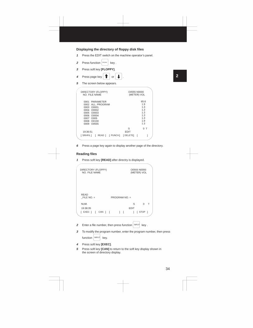
Displaying the directory of floppy disk files
1 Press the EDIT switch on the machine operator’s panel.
2 Press function PRGRM key .
3 Press soft key [FLOPPY] .
4 Press page key or .
5 The screen below appears.
SRHFIL[ ] [ ] [ ] [ ] [ ]READ PUNCH DELETE
O0555 N0000 (METER) VOL
19:36:51 EDIT
0001 PARAMETER0002 ALL. PROGRAM0003 O00010004 O00020005 O00030006 O00040007 O0050008 O01000009 O0555
65.6 1.9 1.3 1.3 1.3 1.3 1.3 1.9 1.3
DIRECTORY (FLOPPY) NO. FILE NAME
S 0 T
6 Press a page key again to display another page of the directory.
Reading files
1 Press soft key [READ] after directry is displayed.
EXEC[ ] [ ] [ ] [ ] [ ]CAN STOP
19:38:35
READ_FILE NO. = PROGRAM NO. =
NUM. S 0 T
O0555 N0000(METER) VOL
DIRECTORY (FLOPPY) NO. FILE NAME
EDIT
2 Enter a file number, then press function INPUT key .
3 To modify the program number, enter the program number, then press
function INPUT key.
4 Press soft key [EXEC] .
5 Press soft key [CAN] to return to the soft key display shown inthe screen of directory display.
2. CRT/MDI OPERATION
35
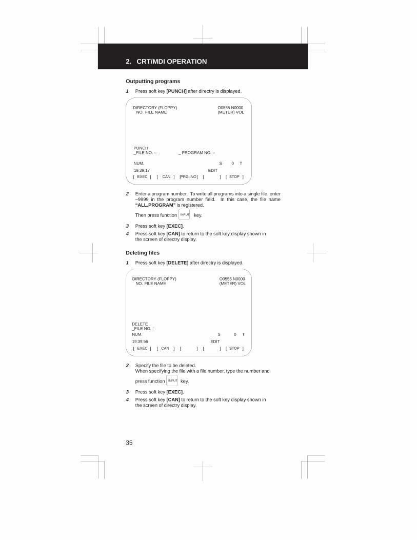
Outputting programs
1 Press soft key [PUNCH] after directry is displayed.
PRG–NOEXEC[ ] [ ] [ ] [ ] [ ]CAN STOP
O0555 N0000(METER) VOL
DIRECTORY (FLOPPY) NO. FILE NAME
19:39:17
PUNCH_FILE NO. = _ PROGRAM NO. =
NUM. S 0 T
EDIT
2 Enter a program number. To write all programs into a single file, enter–9999 in the program number field. In this case, the file name“ALL.PROGRAM” is registered.
Then press function INPUT key.
3 Press soft key [EXEC] .
4 Press soft key [CAN] to return to the soft key display shown inthe screen of directry display.
Deleting files
1 Press soft key [DELETE] after directry is displayed.
EXEC[ ] [ ] [ ] [ ] [ ]CAN STOP
O0555 N0000(METER) VOL
DIRECTORY (FLOPPY) NO. FILE NAME
19:39:56
DELETE_FILE NO. =NUM. S 0 T
EDIT
2 Specify the file to be deleted.When specifying the file with a file number, type the number and
press function INPUT key.
3 Press soft key [EXEC] .
4 Press soft key [CAN] to return to the soft key display shown inthe screen of directry display.

3
1
4
5
6
7
8
9
10
2
36
Procedure for changing the file name
1 Press soft key [RENAME] after directry is displayed.
2 Position the cursor to FILE NO. then enter the number of the file whose
name is to be changed. Press the INPUT key.
3 Position the cursor to NAME and key in a new file name. Then, press
the INPUT key.
4 Press soft key [EXEC] .
5 To return to the previous screen, press the [CAN] soft key.
EXEC[ ] [ ] [ ] [ ] [ ]CAN STOP
O0001 N0000(METER) VOL
FILE DIRECTORY NO. FILE NAME
0001 PARAMETER 87.10002 ALL.PROGRAM 87.10003 O0001 1.90004 O0021 7.10005 O0041 7.10006 O0615 5.80007 O0651 9.10008 O0601 7.10009 O0645 5.8RENAME
FILE NO. = NAME=NUM. S 0 T010121:59:53 EDIT

3. OPERATION LIST
37
Classifi-cation
FunctionKEYSW
S E T-TING
PWE=1Mode
Resetting of operating time—
Reset
Resetting of number of ma-chined parts —
Reset
Resetting of OT alarm At power–up
Resetting of alarm 100 —
Parameter input � MDI mode
Offset input —
Registrationf MDI
Setting data input MDI mode
from MDIPMC parameter input
�� MDI mode
Tool length measurement JOG mode
Parameter input (NC tape)
� EDIT mode
→ memory)� —
Registrationfrom NCtape
PMC parameter input�
� EDIT mode
Offset input EDIT mode
Program registration �
EDIT/AUTOmode
Parameter punch out EDIT mode
PMC parameter punch out EDIT mode
Tape punchout Offset punch out EDIT mode
All programs punch out EDIT mode
One program punch out EDIT mode

3
1
4
5
6
7
8
9
10
2
38
Func-tionkey
Operation
POS →R CAN
POS →P CAN
— ANDP CAN
— ANDCAN RESET
PARAMNo. Parameter number →→ → Data →
→PWE =0 → RESET
INPUT INPUT
OFSET → Offset number → → Offset value→No. INPUT INPUT
PARAM → → → Data →No. 0 INPUT INPUT
DGNOS → Diagnostic number → → Data →No. INPUT INPUT
POS → OFSET
→ Offset number →
(Relative coordinate system display)
→ → Place tool in measurement position →
→
AND→
POS Z CAN
OFSET No.
INPUT EOB Z
PARAM INPUT
PARAM Emergency stop → AND INPUTEOB
DGNOS INPUT
OFSET INPUT
PRGRM INPUT
PARAM OUTPT
DGNOS OUTPT
OFSET OUTPT
PRGRM –9999 →→O OUTPT
PRGRM Program number →→O OUTPT

3. OPERATION LIST
39
Classifi-cation
FunctionKEYSW
S E T-TING
PWE=1Mode
Search for program numberEDIT/AUTO
mode
Search for sequence num-ber
AUTO mode
Search for address/word EDIT mode
SearchSearch for address only EDIT mode
Search for offset number —
Search for diagnostic num-ber —
Search for parameter num-ber —
Display of memory used EDIT mode
Deletion of all programs � EDIT mode
Deletion of one program � EDIT mode
Deletion of multiple blocks � EDIT mode
EditingDeletion of one block � EDIT mode
Word deletion � EDIT mode
Word alteration � EDIT mode
Word insertion � EDIT mode
Collation Memory collationEDIT/AUTO
mode
Program registration �
EDIT/AUTOmode
Output of all programs EDIT mode
I/O to andfrom
Output of one program EDIT mode
FANUCCassette File head search
EDIT/AUTOmode
File deletion � EDIT mode
Program collationEDIT/AUTO
mode

3
1
4
5
6
7
8
9
10
2
40
Func-tionkey
Operation
PRGRM Program number →→ (Cursor)O �
PRGRMProgram number search → → Sequence number search
→ (Cursor)
N
�
PRGRM Data to be searched for → (Cursor)�
PRGRM Address to be searched for → (Cursor)�
OFSET Offset number →→No. INPUT
DGNOS Diagnostic number →→No. INPUT
PARAM Parameter number →→No. INPUT
PRGRM PRGRM
PRGRM –9999 →→O DELET
PRGRM Program number →→O DELET
PRGRM Sequence number →→O DELET
PRGRM →EOB DELET
PRGRM Search for word to be deleted → DELET
PRGRM Search for word to be changed → New data → ALTER
PRGRM
Search for word immediately before insertion location → New data
→ INSRT
PRGRM INPUT
PRGRM File number →→ →N INPUT INPUT
PRGRM –9999 →→O OUTPT
PRGRM Program number →→O OUTPT
PRGRM File number →→N INPUT
PRGRM File number →→N OUTPT
PRGRM File number →→ →N INPUT INPUT

3. OPERATION LIST
41
Classifi-cation
FunctionKEYSW
S E T-TING
PWE=1Mode
Play–back NC data inputTEACH–IN
JOG/HANDLEmode
Memory all clear At power–up
Clear
Parameter clear � At power–up
Clear
Program clear � At power–up
Sub PCB all clear At power–up

3
1
4
5
6
7
8
9
10
2
42
Func-tionkey
Operation
PRGRMMove machine → , or →
→ NC data → → →
X Y Z INSRT
INSRT EOB INSRT
— ANDRESET DELET
— RESET
— DELET
— AND (However, set PWE on main side to 0.)DELET S

4. G CODE LIST
43
M series
G code list (M series) (1/3)
G code Group Function
G00 Positioning
G0101
Linear interpolation
G0201
Circular interpolation/Helical interpolation CW
G03 Circular interpolation/Helical interpolation CCW
G04 Dwell, Exact stop
G05 High speed cycle machining
G0800
Advanced preview control
G0900
Exact stop
G10 Data setting
G11 Data setting mode cancel
G15 17Polar coordinates command cancel
G1617
Polar coordinates command
G17 XpYp plane selection Xp: X axis or its parallel axis
G18 02 ZpXp plane selection Yp: Y axis or its parallel axis
G19 YpZp plane selection Zp: Z axis or its parallel axis
G2006
Input in inch
G2106
Input in mm
G22 04Stored stroke check function on
G2304
Stored stroke check function off
G27 Reference position return check
G28 Return to reference position
G29 00 Return from reference position
G30 2nd, 3rd and 4th reference position return
G31 Skip function
G33 01 Thread cutting
G3700
Automatic tool length measurement
G3900
Corner offset circular interpolation
G40 Cutter compensation cancel
G41 07 Cutter compensation left
G42 Cutter compensation right
G4308
Tool length compensation + direction
G4408
Tool length compensation – direction
G45 Tool offset increase
G4600
Tool offset decrease
G4700
Tool offset double increase
G48 Tool offset double decrease
G49 08 Tool length compensation cancel
G50 11Scaling cancel
G5111
Scaling
G5200
Local coordinate system setting
G5300
Machine coordinate system selection

3
1
4
5
6
7
8
9
10
2
44
G code list (M series) (2/3)
G code Group Function
G54 Workpiece coordinate system 1 selection
G55 Workpiece coordinate system 2 selection
G5614
Workpiece coordinate system 3 selection
G5714
Workpiece coordinate system 4 selection
G58 Workpiece coordinate system 5 selection
G59 Workpiece coordinate system 6 selection
G60 00 Single direction positioning
G61 Exact stop mode
G6215
Automatic corner override
G6315
Tapping mode
G64 Cutting mode
G65 00 Macro call
G6612
Macro modal call
G6712
Macro modal call cancel
G6816
Coordinate rotation
G6916
Coordinate rotation cancel
G7309
Peck drilling cycle
G7409
Counter tapping cycle
G75 01 Plunge grinding cycle (0–GSC)
G76 09 Fine boring cycle
G77
01
Direct constant–dimension plunge grinding cycle(0–GSC)
G7801
Continuous–feed surface grinding cycle (0–GSC)
G79 Intermittent–feed surface grinding cycle (0–GSC)
G80Canned cycle cancel/external operation function can-cel
G81Drilling cycle, spot boring cycle or external operationfunction
G82 Drilling cycle or counter boring cycle
G83 09 Peck drilling cycle
G84 Tapping cycle
G85 Boring cycle
G86 Boring cycle
G87 Back boring cycle
G88 Boring cycle
G89 Boring cycle
G9003
Absolute command
G9103
Increment command
G92 00Setting for work coordinate system or clamp at maxi-mum spindle speed
G94 05Feed per minute
G9505
Feed per rotation
G9613
Constant surface speed control
G9713
Constant surface speed control cancel
G9810
Return to initial point in canned cycle
G9910
Return to R point in canned cycle
G107 00 Cylindrical interpolation

4. G CODE LIST
45
G code list (M series) (3/3)
G code Group Function
G150 Normal direction control cancel mode
G151 19 Normal direction control left side on
G152 Normal direction control right side on
G160 20 In–feed control function cancel (0–GSC)
G161 20 In–feed control function (0–GSC)
CAUTION1. Multiple G codes of different groups can be specified in a single
block. When multiple G codes of one group are specified in a block,the G code specified last is effective.
2. If any G code of group 01 is specified in a canned cycle mode, thecanned cycle is automatically cancelled and the G80 condition isentered. However, a G code of group 01 is not affected by any ofthe canned cycle G codes.
NOTE
1. Modal G codes have the following initial conditions when the power isturned on or the system is reset to the clear state (bit 6 of parameter No.045).
1) Those G codes marked in Table 3 are specified automatically.
2) G20 and G21 retain their original conditions.
3) When the power is turned on, G22 is specified automatically. Whenthe system is reset, G22 and G23 retain their original conditions.
4) G00 or G01 is automatically selected depending on the setting ofbit 6 of parameter No. 011.
5) G90 or G91 is automatically selected depending on the setting ofbit 7 of parameter No. 030.
2. The G codes of group 00, except G10 and G11, are one–shot G codes.
3. If a G code that does not appear in the G code list is specified, or a Gcode whose options are not supported is specified, alarm No. 010 isdisplayed.
4. A G code is displayed from each group.

3
1
4
5
6
7
8
9
10
2
46
T series
G code list (T series) (1/2)G code system
(Note 7) Group FunctionA B C
p
G00 G00 G00 Positioning (rapid traverse)
G01 G01 G01 01 Linear interpolation (feed)
G02 G02 G02 Circular interpolation CW
G03 G03 G03 Circular interpolation CCW
G04 G04 G04 Dwell
G10 G10 G10 00 Data setting
G11 G11 G11 Data setting mode cancel
G17 G17 G17 XpYp plane selection
G18 G18 G18 16 ZpXp plane selection
G19 G19 G19 YpZp plane selection
G20 G20 G7006
Inch data input
G21 G21 G7106
Metric data input
G22 G22 G2209
Stored stroke check function ON
G23 G23 G2309
Stored stroke check function OFF
G25 G25 G2508
Spindle speed fluctuation detect OFF
G26 G26 G2608
Spindle speed fluctuation detect ON
G27 G27 G27 Reference point return check
G28 G28 G2800
Return to reference point
G30 G30 G3000
2nd, 3rd, 4th reference point return
G31 G31 G31 Skip cutting
G32 G33 G3301
Thread cutting
G34 G34 G3401
Variable–lead thread cutting
G36 G36 G3600
Automatic tool compensation X
G37 G37 G3700
Automatic tool compensation Z
G40 G40 G40 Tool nose radius compensation cancel
G41 G41 G41 07 Tool nose radius compensation left
G42 G42 G42 Tool nose radius compensation right
G50 G92 G92
00
Coordinate system setting, max. spindlespeed setting
G52 G52 G5200
Local coordinate system setting
G53 G53 G53 Machine coordinate system setting
G54 G54 G54 Workpiece coordinate system 1 setting
G55 G55 G55 Workpiece coordinate system 2 setting
G56 G56 G5614
Workpiece coordinate system 3 setting
G57 G57 G5714
Workpiece coordinate system 4 setting
G58 G58 G58 Workpiece coordinate system 5 setting
G59 G59 G59 Workpiece coordinate system 6 setting
G65 G65 G65 00 Macro calling
G66 G66 G6612
Macro modal call
G67 G67 G6712
Macro modal call cancel
G68 G68 G68
04
Mirror image for double turrets ON or balancecut mode (0–TTC)
G69 G69 G6904
Mirror image for double turrets OFF or bal-ance cut mode cancel (0–TTC)

4. G CODE LIST
47
G code list (T series) (2/2)
G code system(Note 7) Group Function
A B Cp
G70 G70 G72Finishing cycle (other than 0–GCC or 00–GCC)
G71 G71 G73Stock removal in turning(other than 0–GCC or 00–GCC)
G72 G72 G74Stock removal in facing(other than 0–GCC or 00–GCC)
G73 G73 G75 00Pattern repeating (other than 0–GCC or 00–GCC)
G74 G74 G76Peck drilling on Z axis(other than 0–GCC or 00–GCC)
G75 G75 G77Grooving on X axis(other than 0–GCC or 00–GCC)
G76 G76 G78Multiple threading cycle(other than 0–GCC or 00–GCC)
G71 G71 G72 Traverse grinding cycle (0–GCC, 00–GCC)
G72 G72 G73Traverse direct constant dimension grindingcycle (0–GCC, 00–GCC)
G73 G73 G7401 Oscillation grinding cycle
(0–GCC, 00–GCC)
G74 G74 G75Oscillation direct constant–dimension grind-ing cycle (0–GCC, 00–GCC)
G80 G80 G80 Canned cycle for drilling cancel
G83 G83 G83 Cycle for face drilling
G84 G84 G84 Cycle for face tapping
G86 G86 G86 10 Cycle for face boring
G87 G87 G87 Cycle for side drilling
G88 G88 G88 Cycle for side tapping
G89 G89 G89 Cycle for side boring
G90 G77 G20
01
Outer diameter/internal diameter cuttingcycle
G92 G78 G2101
Thread cutting cycle
G94 G79 G24 Endface turning cycle
G96 G96 G9602
Constant surface speed control
G97 G97 G9702
Constant surface speed control cancel
G98 G94 G9405
Per minute feed
G99 G95 G9505
Per revolution feed
— G90 G90 03 Absolute programming
— G91 G9103
Incremental programming
— G98 G9811
Return to initial level
— G99 G9911
Return to R point level
G107 G107 G107 00 Cylindrical interpolation
G112 G112 G11221
Polar coordinate interpolation mode
G113 G113 G11321
Polar coordinate interpolation cancel mode
G250 G250 G250 20 Polygonal turning cancel
G251 G251 G251 Polygonal turning

3
1
4
5
6
7
8
9
10
2
48
CAUTION1. A number of G codes can be specified in the same block. When
more than one G code of the same group is specified, the G codespecified later is effective.
2. If any G code of group 01 is specified in a canned cycle mode, thecanned cycle is automatically cancelled and the G80 condition isentered. However a G code of group 01 is not affect4ed by any ofthe canned cycle G codes.
NOTE
1. G codes marked are initial G codes when turning power on. For G20 and G 21, the G code before turning power off remains. G00or G01 can be selected by parameter setting.
2. G codes of group 00 are not modal. They are only effective in the blockin which they are specified.
3. If a G code not listed on the table of G codes is inputted, or optional Gcode not specified in the system is commanded, an alarm (No. 010) isdisplayed.
4. A G code is displayed from each group.
5. G code system B and C are options. Whether G code system B or C isset by parameter No. 0036: GSPC.

5. PROGRAM FORMAT
49
Functions Explanation
Positioning (G00)
Start point
P
Linear interpolation(G01)
Start point
P
Circular interpolation (G02, G03)
(x, y)
G03(x, y)
JR
I
G02
Start point
Start point
R
I
J
Center End point
Center
Helical cutting (G02, G03)
Z
Tool path
YX
The feedrate along the circumferenceof two circular interpolated axes is thespecified feedrate.
Startpoint
End point
3
1
4
5
6
7
8
9
10
2
50
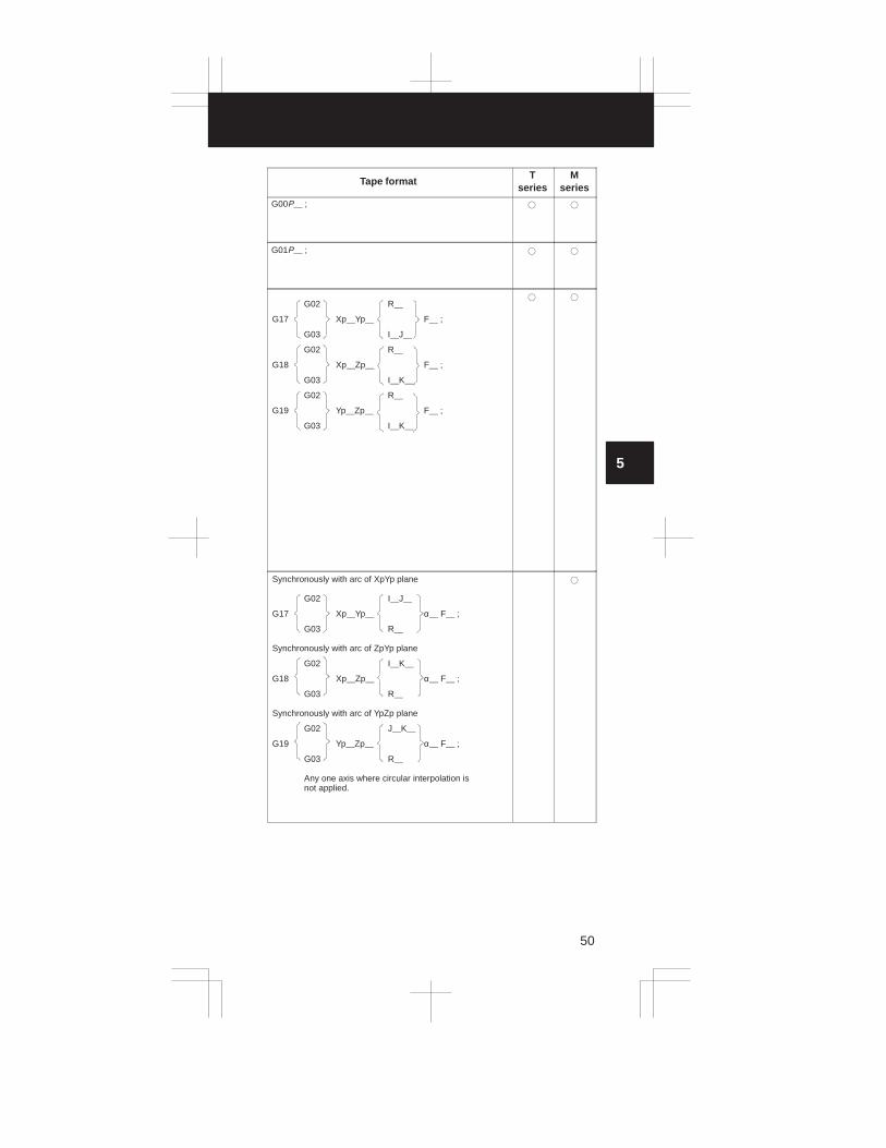
Tape formatT
seriesM
series
G00P__ ; � �
G01P__ ; � �
G02 R__
G17 Xp__Yp__ F__ ;
G03 I__J__
G02 R__
G18 Xp__Zp__ F__ ;
G03 I__K__
G02 R__
G19 Yp__Zp__ F__ ;
G03 I__K__
� �
Synchronously with arc of XpYp plane
G02 I__J__
G17 Xp__Yp__ α__ F__ ;
G03 R__
Synchronously with arc of ZpYp plane
G02 I__K__
G18 Xp__Zp__ α__ F__ ;
G03 R__
Synchronously with arc of YpZp plane
G02 J__K__
G19 Yp__Zp__ α__ F__ ;
G03 R__
Any one axis where circular interpolation is not applied.
�

5. PROGRAM FORMAT
51
Functions Explanation
Dwell (G04) (Example)G04 P1000; Dwell by 1 seconds
Exact stop(G04, G09) Speed
Time
High-speed cycle machining (G05)
(Example)Cycle 1: connection 2, repetition 1Cycle 2: connection 3, repetition 3Cycle 3: connection 0, repetition 1G05P10001L2;Cycle is executed as 1, 2, 2, 2, 3, 1, 2, 2, 2, 3
High-speed remote buffer A (G05)
Specify G05 only in a block using normal NC command format. Then specify move data in the special format explained next page. When zero is spe-cified as the travel distance along all axes, normal NCcommand format can be used again for subsequent command specification.
High-speed remote buffer B (G05)
High-speed remote buffer A uses binary data.On the other hand, high-speed remote buffer B can di-rectly use NC language coded with equipment such asan automatic programming unit to perform high-speed machining.
Advanced preview control (G08)
This function can minimize the delay caused by accel-eration/deceleration, which increases together with thefeedrate, as well as the delay in the servo system. Toolmovement can thus faithfully follow the command val-ues, reducing the degree of error in the machined figure.
3
1
4
5
6
7
8
9
10
2
52
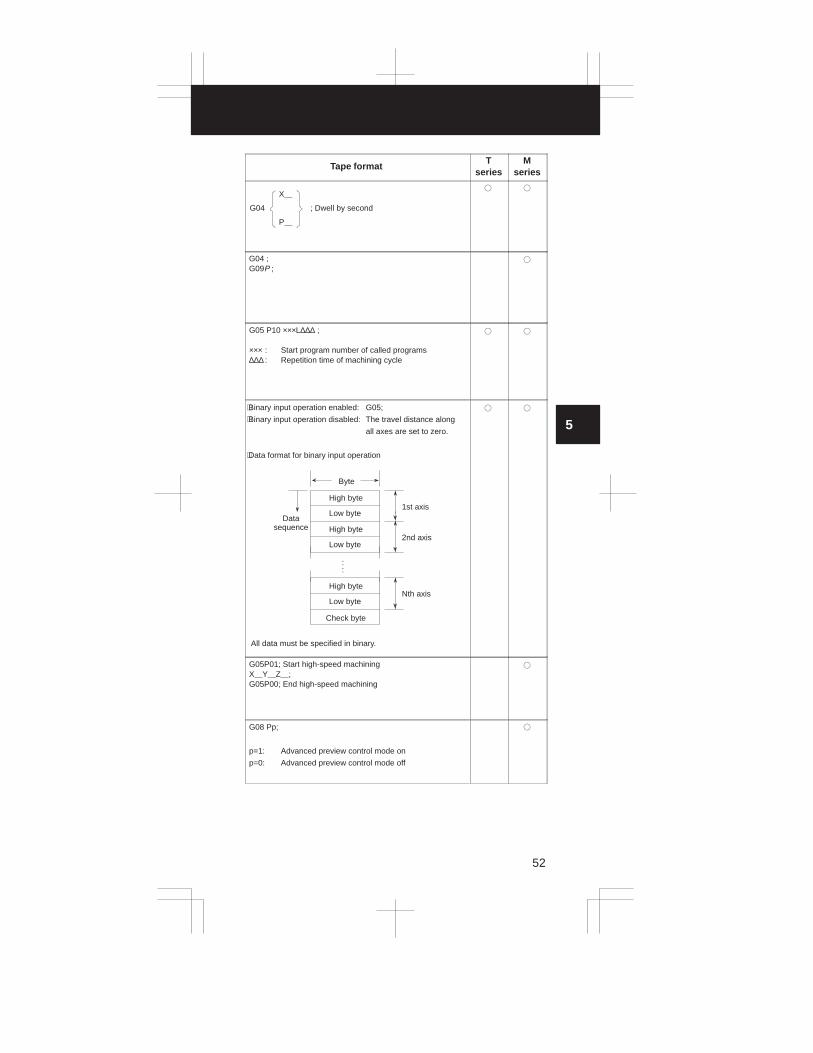
Tape formatT
seriesM
series
X__
G04 ; Dwell by second
P__
� �
G04 ;G09P ;
�
G05 P10 ×××L∆∆∆ ;
××× : Start program number of called programs∆∆∆ : Repetition time of machining cycle
� �
⋅Binary input operation enabled: G05;
⋅Binary input operation disabled: The travel distance along
all axes are set to zero.
⋅Data format for binary input operation
Byte
High byte
Low byte
High byte
Low byte
High byte
Low byte
Check byte
1st axis
2nd axis
Nth axis
Datasequence
All data must be specified in binary.
::
� �
G05P01; Start high-speed machiningX__Y__Z__;G05P00; End high-speed machining
�
G08 Pp;
p=1: Advanced preview control mode on
p=0: Advanced preview control mode off
�

5. PROGRAM FORMAT
53
Functions Explanation
Change of offset value byprogram (G10)
The tool compensation amount can be set or changedwith the G10 command.When G10 is used in absolute input (G90), the compensation amount specified in the command becomes the new tool compensation amount. When G10 is used in incremental input (G91), the compensation amount specified in the command isadded to the amount currently set.
Change of offset value byprogram (G10)
Change of parameter byprogram (G10)
The parameter value can be changed by the machining program.
Polar coordinate command mode (G15, G16)
X
Y
xy
XpYp plane selection(G17)ZpXp plane selection(G18)YpZp plane selection(G19)
G17
X
Y
G18 G19
Z
X
Y
Z
Inch/metric conversion(G20, G21)
Extended stored strokelimit check on(G22, G23)
(I, J, K)
(X, Y, Z)
X>I, Y>J, Z>K

3
1
4
5
6
7
8
9
10
2
54
Tape formatT
seriesM
series
G10P__X (U)__Y (V)__Z (W)__R (C)__Q__;For geometry offset amount
P=10000+geometry offset numberFor offset amount
P= wear offset numberR : Tool nose radius offset valueQ : Imaginary tool nose number
�
G10L__PpRr;p : Offset No.r : Tool compensation amountFormat(1) For tool compensation memory A
G10 L11 P__R__;(2) For tool compensation memory B
Setting/changing the geometric compensation amountG10 L10 P__R__;Setting/changing the wear compensation amountG10 L11 P__R__;
�
G10 L50 ;N__P__ ;G11
N : Parameter numberP : Parameter value
� �
G16 ; Polar coordinate commandXx Yy ;x: radius, y: angle (* )
G15 ; Polar coordinate command cancel
�
G17 ;
G18 ;
G19 ;
� �
G20 ; Inch inputG21 ; Metric input
� �
G22X__Y__Z__I__J__K__ ; on
G23 ; off
(X, Z, I and K only for T series)
� �

5. PROGRAM FORMAT
55
Functions Explanation
No check
Spindle speedfluctuation detectionon (G26)Spindle speedfluctuation detectionoff (G25)
(Example)
(1) When an alarm is raised after a specified spindle speed is reached
Reference for spindle speed at which check is started
Spindle speed
Specifiedspeed
Fluctuation at whichalarm is raised (r)
Actual speed(detected by positioncoder)
No check
Time
CheckCheck
r
Specification of another speed
Alarm
Start of check
(2) When an alarm is raised before a specified spindle speed is reached
Spindle speed
Specifiedspeed
TimeCheckCheck
r
Specification of another speed
Alarm
Start of check
P
q
Spindle speed specified by q
Spindle speed specified by r
Actualspeed
Reference position
return check (G27)
Start point
P
Reference position

3
1
4
5
6
7
8
9
10
2
56
Tape formatT
seriesM
series
G26PpQqRr ; spindle fluctuation detection on
p: Time (in ms) from the issue of a new spindle rotationcommand (S command) to the start of checking whetherthe actual spindle speed is so fast that an overheat canoccur. (When a specified speed is reached within the timeperiod of P, a check is started at that time.)
q: Tolerance (%) of a specified spindle speed (If a specifiedspindle speed lies within this range, it is regarded ashaving reached the specified value. Then, the checkingof an actual spindle speed is started.)
q = (1 – actual spindle speed/specified spindle speed) × 100
r: Spindle speed fluctuation (%) at which the actual spindlespeed is so fast that an overheat can occur
r = (1 – speed that can cause overheat/specified spindlespeed) × 100
G26 enables the spindle speed fluctuation detection function, and G25 disables the spindle speed fluctuationdetection.
G25 ; Spindle fluctuation detection off
�
G27P__ ; � �

5. PROGRAM FORMAT
57
Functions Explanation
Reference position
return (G28)
2nd, 3rd, 4th reference
position return (G30)
Start point
Reference poisition
Intermediate point
P
Return to reference
position return start
position (G29)
Intermediate position
Reference position
P
Skip function (G31)
Multi-step skip function
(G31)
Start point
Skip signal
P
Equal lead thred cutting
(G32)
�
F: LeadThread cutting (G33)
F: Lead
Variable lead thread
cutting
Automatic tool com-
pensation (G36, G37)
Specified position(Xa or Za)
Starting pointMeasured positionreach signal
Offset value setby this command
Measuredposition

3
1
4
5
6
7
8
9
10
2
58
Tape formatT
seriesM
series
G28P__ ;P2
G30 P3 P__ ;P4
P2: 2nd reference position returnP3: 3rd reference position returnP4: 4th reference position return
� �
G29P__ ; �
G31P__F__ ; � �
Move commandG31P__F__P__;
F__: FeedrateP__: P1-P4
DwellG04X (U, P)__(Q__);
X(U, P)__: Dwell timeQ__: Q1-Q4
GCC
G32P__F__ ; �
G33P__F__ ; �
G34P__FfKf ;f: Longer axis lead at the start positionk: increase/decrease value per spindle revolution
�
G36X xa ;
G37Z za ;
X xa, Z za: Specified position
�

5. PROGRAM FORMAT
59
Functions Explanation
Automatic tool length
measurement (G37)
ÇÇZ
0 X
Rapidtraverse
Measurementfeedrate
A (Start position)Measurement position is commanded with G37
B (Deceleration position)
C (Measurement position)The tool stops when the approach end signal goes on.
Compensation value = (Current compensation value) + [(Coordinates of the point at which the tool is stopped) – (Coordinates of the programmed measurement position)]
Tool nose radius
compensation
(G40, G41, G42) ÇÇÇÇÇÇ
ÇÇÇÇÇÇÇÇÇÇ
G41
G42
G40
G40 : Programmed path
G41 : Left of programmed path
G42 : Right of programmed path
Cutter compensation B
(G39 to G42)
Cutter compensation
(G40 to G42) ÇÇÇÇ
ÇÇÇÇÇÇÇÇÇÇÇÇÇ
G41
G42
G40
G40 : Programmed path
G41 : Left of programmed path
G42 : Right of programmed path
Tool length
compensation A, B, C
(G43, G44, G49)
Z
OffsetG43: + offsetG44: – offset
3
1
4
5
6
7
8
9
10
2
60
Tape formatT
seriesM
series
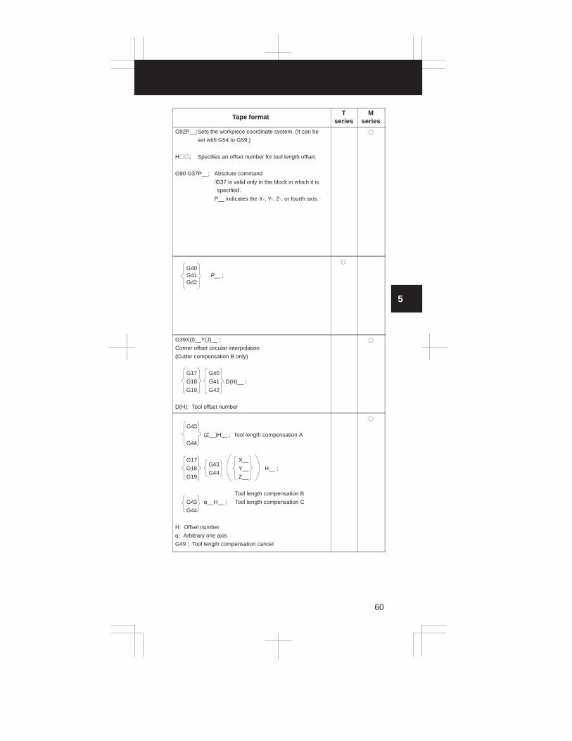
G92P__;Sets the workpiece coordinate system. (It can be
set with G54 to G59.)
H��; Specifies an offset number for tool length offset.
G90 G37P__; Absolute command
⋅G37 is valid only in the block in which it is
specified.
P__ indicates the X-, Y-, Z-, or fourth axis.
�
G40G41 P__ ;G42
�
G39X(I)__Y(J)__ ;
Corner offset circular interpolation
(Cutter compensation B only)
G17 G40
G18 G41 D(H)__ ;
G19 G42
D(H): Tool offset number
�
G43
(Z__)H__ ; Tool length compensation A
G44
G17 X__
G18 Y__ H__ ;
G19 Z__
Tool length compensation B
G43 α__H__ ; Tool length compensation C
G44
H: Offset number
α: Arbitrary one axis
G49 ; Tool length compensation cancel
G43
G44
�

5. PROGRAM FORMAT
61
Functions Explanation
Tool offset
(G45 – G48)
ÔÔÔ Double increase
ÔÔÔÔÔÔÔÔÔÔÔÔÔÔÔÔÔÔÔ
Double decrease
Decrease
IncreasesG45
G46
G47
G48
: offset value P
Coordinate system
setting
Spindle speed setting
(G50)
X
Z
Scaling (G50, G51)P4
P4’
P3
P3’
P0
P1’
P1
P2’
P2
P1 to P4: Programmed shapeP1’ to P4’: Scaled shapeP0: Scaling center
Local coordinatesystem setting (G52)
(Local coordinate system)
(Workpiece coordinate system 2:G55)
(Workpiece coordinate system)
(Workpiece coordinate system 6:G59)
(Machine coordinate system)
(Local coor-dinate sys-tem)
(Workpiece referenceposition offset)
(Workpiece coordinate system 1: G54)
(Origin of the machine coordinate system)
(Parametervalue)
(Reference position)
P
P
Machine coordinate system selection (G53)

3
1
4
5
6
7
8
9
10
2
62
Tape formatT
seriesM
series
G45 (increase)
G46 (decrease)
G47 (double increase)
G48 (double decrease)
X__Y__ Dxx ;Z__
�
G50X__Z__ ; Coordinate system settingG50S__ ; Spindle speed setting
�
G51X__Y__Z__P__(or I__J__K__) ;
G50 ; Cancel
X, Y, Z: Scaling center
P: Magnification
(I, J, and K are the scaling magnifications for the X-, Y-, andZ-axes respectively.)
�
G52P__ ; Local coordinate system setting
G52P0 ; Local coordinate system cancel
� �
G53P__ ; � �

5. PROGRAM FORMAT
63
Functions Explanation
Work coordinatesystem 1 – 6selection(G54 – G59)
ZOFS2 ZOFS3 ZOFS4
ZOFS5ZOFS1
ZOFS6
Workpiece coordinate system 1
Workpiece coordinate system 2
Workpiece coordinate system 3
Workpiece coordinate system 4
Workpiece coordinate system 5
Workpiece coordinate system 6
Machine reference position
ZOFS1: Reference position offset for workpiece coordinate system 1ZOFS2: Reference position offset for workpiece coordinate system 2ZOFS3: Reference position offset for workpiece coordinate system 3ZOFS4: Reference position offset for workpiece coordinate system 4ZOFS5: Reference position offset for workpiece coordinate system 5ZOFS6: Reference position offset for workpiece coordinate system 6
Additioonal work coordinate systemselection (G54P)
(Example)G54P12 ;Selecting additional work coordinate system 12
Spindle direction
positioning (G60)
End point
End point
Start point
Temporary stop
Overrun
Start point
Exact stop mode (G61)Speed
Time
Automatic corner over-
ride (G62) Programmed path
a
a
Le Ls
Override is applied from a to b

3
1
4
5
6
7
8
9
10
2
64
Tape formatT
seriesM
series
G54P__ ; Work coordinate system 1 selectionG55P__ ; Work coordinate system 2 selectionG56P__ ; Work coordinate system 3 selectionG57P__ ; Work coordinate system 4 selectionG58P__ ; Work coordinate system 5 selectionG59P__ ; Work coordinate system 6 selection
� �
G54Pn ; (n=1 – 64) �
G60P__ ; �
G61 ; �
G62 ; �

5. PROGRAM FORMAT
65
Functions Explanation
Tapping mode (G63)Feed hold is ineffective
Feedrate overrideis ineffective
Time
Speed
Cutting mode (G64)
Time
Speed
Macro call (G65)
O__:
G66P0001L__:
M02;
O0001;
M99
Main program Macro program
Macro model call
(G66, G67)
G66P0001L__;X__
O__:
G67;
O0001;
M99
Main program Macro program
Y__
Mirror image for double
turrets (G68, G69)
Coordinate rotation
(G68, G69)Y’ X’
Y
XR

3
1
4
5
6
7
8
9
10
2
66
Tape formatT
seriesM
series
G63 ; �
G64 ; �
G65 P__L__ ;
P: Program numberL: Repetition count (1 to 9999)
� �
G66 P__L__ ;G67 ; Cancel
P: Program numberL: Repetition count (1 to 9999)
� �
G68 ;Mirror image for double turretsG69 ;Mirror image cancel
TT
G17G18 G68 α__β__R__ ;G19
G69 ;α, β: 3 axes corresponding to G17, G18, G19R: Routation angle
�

5. PROGRAM FORMAT
67
Functions Explanation
Canned cycle
G90: Outer diameter/internal diameter cutting cycle
G92: Thread cutting cycle
G94: End face turning cycle
Multiple repetitive cycle
G70: Finishing
G71: Stock removal in turning
G72: Stock removal in facing
G73: Pattern repeating
G74: End face peck drilling cycle
G75: Outer diameter/internal diameter drilling cycle
G76: Multiple thread cutting cycle
(Example) G92
Canned cycle for lathes
(G70 to G76)(G90, G92, G94)
X axisZ W
Zero point
3(R) 4(R)
3(R)1(R) U/2
X/2Z axis
Approx.45°
r(The chamfered angle in the left figure is 45 degreesor less because of the delay in the servo system.)
L
Detailed chamfered thread
R Rapid . traverse
F Specified. by F code

3
1
4
5
6
7
8
9
10
2
68
Tape formatT
seriesM
series
G70 P__Q__ ;
G71 U__R__ ;
G71 P__Q__U__W__F__S__T__ ;
G72 W__R__ ;
G72 P__Q__U__W__F__S__T__ ;
G73 W__R__ ;
G73 P__Q__U__W__F__S__T__ ;
G74 R__ ;
G74 X(u)__Z(w)__P__Q__R__F__ ;
G75 R__ ;
G75 X(u)__Z(w)__P__Q__R__F__ ;
G76 R__ ;
G76 X(u)__Z(w)__P__Q__R__F__ ;
G90
G92 X__Z__I__F__ ;
G94 X__Z__I__F__ ;
�

5. PROGRAM FORMAT
69
Functions Explanation
Canned cycle for grinding (G71 – G74)
G73: High-speed peck drilling cycle
G74: Left-hand tapping cycle
G71: Traverse grinding cycle
G72: Traverse direct fixed-dimension grinding cycle
G73: Oscillation grinding cycle
G74: Oscillation direct fixed-dimention grinding cycle
(Example) G71
G71 A__B__W__U__I__K__H__ ;
A: First depth of cut
B: Second depth of cut
W: Grinding range
U: Dwell time Maximum specification
time: 99999.999 seconds
I: Feedrate of A and B
K: Feedrate of W
H: Number of repetitions
Setting value: 1 to 9999
Canned cycle (G73, G74,G80 – G89)
X
Z
A
BU
6(K)
3(K)
W
1(1)2
4(1)5
G76: Fine boring cycle
G80: Cancel
G81: Drilling cycle, spot drilling cycle
G82: Drilling cycle, counter boring cycle
G83: Peck drilling cycle
G84: Tapping cycle
G85: Boring cycle
G86: Boring cycle
G87: Boring cycle/Back boring cycle
G88: Boring cycle
G89: Boring cycle(Example)
G73 (G98)
R point
Z point
q
q
q
d
d
G73 (G99)
R point
Z point
q
q
q
d
d
Initial level

3
1
4
5
6
7
8
9
10
2
70
Tape formatT
seriesM
series
G71 A__B__W__U__I__K__H__ ;G72 P__A__B__W__U__I__K__H__ ;G73 A__(B__)W__U__I__K__H__ ;G74 P__A__(B__)W__U__I__K__H__ ;
G73 X__Y__Z__P__Q__R__F__K__ ;G74 X__Y__Z__P__Q__R__F__K__ ;G76 X__Y__Z__P__Q__R__F__K__ ;G81 X__Y__Z__P__Q__R__F__K__ ;G82 X__Y__Z__P__Q__R__F__K__ ;G83 X__Y__Z__P__Q__R__F__K__ ;G84 X__Y__Z__P__Q__R__F__K__ ;G85 X__Y__Z__P__Q__R__F__K__ ;G86 X__Y__Z__P__Q__R__F__K__ ;G87 X__Y__Z__P__Q__R__F__K__ ;G88 X__Y__Z__P__Q__R__F__K__ ;G89 X__Y__Z__P__Q__R__F__K__ ;G80 ; CancelG� � X__Y__Z__R__Q__P__F__K__ ;
Drilling mode
Hole position data
Drilling dataNumber of repeat
GCC
�
Item Address Explanation
Drilling mode G� � G73, G74, G76, G80 – G89
Hole position data X,Y Specifies the hole position by an incremental or absolute value.
Drilling data Z Specifies the distance from point R to thebottom of the hole.
R Specifies the distance from the initial level to point R.
Q Specifies each cut-in value with G73 andG83 or the shift value with G76 and G87.(Always specified with an incrementalvalue.)
P Specifies the dwell time at the bottom ofthe hole.
F Specifies the feed rate.
Number of repeats K Specifies the number of repeats for a series of operation 1 to 6.

5. PROGRAM FORMAT
71
Functions Explanation
G75: Plunge grinding cycle
G77: Direct constant-dimension plunge
grinding cycle
G78: Continuous-feed surface grinding cycle
G79: Intermittent-feed surface grinding cycle
G83: Front drilling cycle
Canned grinding cycle
(G75, G77, G78, G79)
Canned cycle for
X
I
X(Z)
J
X(Z)
(1) (R)
(2) P
(3) (F)
(4) (R)
(5) P
(6) (F)
(Example)
G75 I__J__K__X (Z)__R__F__P__L__ ;
I: Depth-of-cut 1 (A sign in the command specifies the direction of cutting.)
J: Depth-of-cut 2 ( A sign in the command specifies the direction of cutting.)
K: Total depth of cut
X (Z): Range of grinding (A sign in the command specifies the direction of
grinding.)
R: Feedrate for I and J
F: Feedrate for X (Z)
P: Dwell time
L: Grinding-wheel wear compensation (Note 1)
G84: Front tapping cycle
G85: Front boring cycle
G87: Side drilling cycle
G88: Side tapping cycle
G89: Side boring cycle
G80: Drilling cycle cancel
q
drilling (G80 to G89)
(Example)G83 (G87) (G99 mode)
(Ma)
d
Z point
R point level
q
q
(Ma)
d
Z point
q
q
R point level
Initial level
dwell
G83 (G87) (G98 mode)
(Mβ), ’dwell
P
PdwellP
(Mβ), ’dwell
P
q
3
1
4
5
6
7
8
9
10
2
72
Tape formatT
seriesM
series
G75 I__J__K__X (Z)__R__F__P__L__ ;G77 I__J__K__X (Z)__R__F__P__L__ ;G78 I__J__K__X (Z)__R__F__P__L__ ;G79 I__J__K__X (Z)__R__F__P__L__ ;
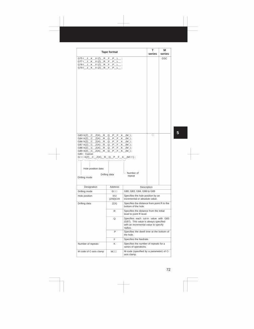
G83 X(Z)__C__Z(X)__R__Q__P__F__K__(M_) ;G84 X(Z)__C__Z(X)__R__Q__P__F__K__(M_) ;G86 X(Z)__C__Z(X)__R__Q__P__F__K__(M_) ;G87 X(Z)__C__Z(X)__R__Q__P__F__K__(M_) ;G88 X(Z)__C__Z(X)__R__Q__P__F__K__(M_) ;G89 X(Z)__C__Z(X)__R__Q__P__F__K__(M_) ;G80 ; CancelG�� X(Z)__C__Z(X)__R__Q__P__F__K__(M��) ;
Number of repeat
Drilling mode
Hole position data
Drilling data
�
GSC
Designation Address Description
Drilling mode G�� G80, G83, G84, G86 to G89
Hole position X/U(Z/W)C/H
Specifies the hole position by an incremental or absolute value.
Drilling data Z(X) Specifies the distance from point R to thebottom of the hole.
R Specifies the distance from the initial level to point R level.
Q Specifies each cut-in value with G83(G87). This value is always specified with an incremental value to specify radius.
P Specifies the dwell time at the bottom ofthe hole.
F Specifies the feedrate.
Number of repeats K Specifies the number of repeats for a series of operations.
M code of C-axis clamp M�� M-code (specified by a parameter) of C-axis clamp.

5. PROGRAM FORMAT
73
Functions Explanation
Absolute/Incremental
command (G90/G91) 60
30
50 100
(Example)
Absoulute command G90X100Y60 ;Incremental command G91X50Y30 ;
Change of workpiece
coordinate system (G92)P
ÇÇÇÇÇÇ
Y
X
Feed/minute,
Feed/revolution
(G94, G95)F
Movedistanceper minute F
Movedistanceper revolution
Feed/minute (G94) Feed/revolution (G95)
Constant suface speed
control (G96, G97)Surface speed
Constant surface speed
control (G96, G97)X
Z(X=0)
Initial point return/R
point return (G98, G99)G98
Initial point
R point
Z point
G99
Cylindrical interpolation(G107)
Z
C
R

3
1
4
5
6
7
8
9
10
2
74
Tape formatT
seriesM
series
G90__ ; Absolute commandG91__ ; Incremental commandG90__G91__ ; Change of workpiece coordinate system
�
(G codesystemB, C)
�
G92P__ ; �
G94 F__ ;. . . . . .
G95 F__ ;. . . . . . or
G98 F__ ;. . . . . .
G99 F__ ;. . . . . .
(T series <G code system B, C> M series)
(T series <G code system A>
� �
G96 Ss ;
G97 ; Cancel
s: Surface speed (m/min or feet/min)
�
G96 Ss Pα ;G97; Cancel
α: 1 – 3(X axis, Y axis, Z axis)
s: Surface speed (m/min or feet/min)
�
G98__ ;G99__ ;
�
(Gcoed
systemB, C)
�
G107 Cr;Cylindrical interpolation mode
C: Rotary axis namer: Radius of cylinderG107 CO;
Cylindrical interpolation mode cancel
� �

5. PROGRAM FORMAT
75
Functions Explanation
Polar coordinate interpolation mode(G112, G113)
X axis
C
C axis
Normal direction control
(G140, G141, G142)
Normal direction(proceeding direction)
Programmed path
C axis
Tool
C axis
Tool
Infeed control (G160,
G161)
Start point
(Example)
End point
r r r r
Y
Z
Polygon turning
(G250, G251)
ToolWorkpieceWorkpiece
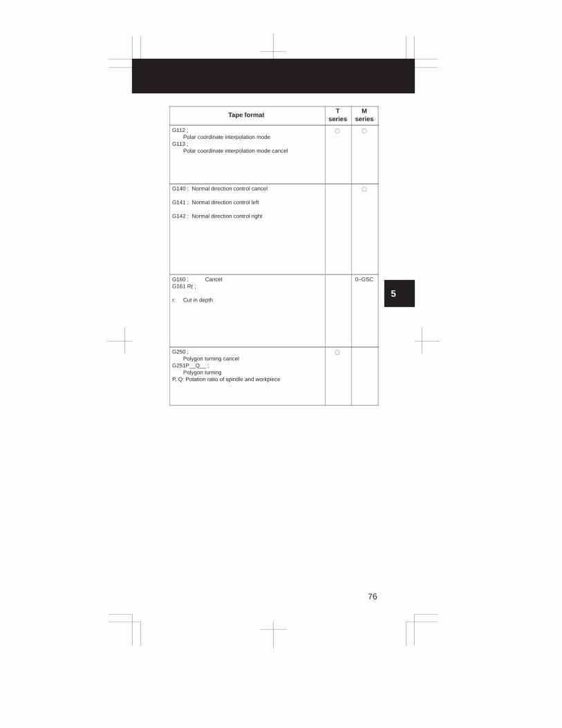
3
1
4
5
6
7
8
9
10
2
76
Tape formatT
seriesM
series
G112 ; Polar coordinate interpolation mode
G113 ;Polar coordinate interpolation mode cancel
� �
G140 ; Normal direction control cancel
G141 ; Normal direction control left
G142 ; Normal direction control right
�
G160 ; CancelG161 Rr ;
r: Cut in depth
0–GSC
G250 ;Polygon turning cancel
G251P__Q__ ;Polygon turning
P, Q: Potation ratio of spindle and workpiece
�

5. PROGRAM FORMAT
77
FS0–TC/FS15–TA format comparison table
Function comparison
A : Both models have the same functions and formats.B : Both models have the same functions, but different formats.C : Both models have the same formats, but different functions.D : The models have different functions and formats.
Item Function FS15–TA
1 Positioning G00X––Z––;
2 Linear interpolation G01X––Z––F––;
3 Circular interpolation G02/03X––Z––R––(I––K––)F––;
4 Dwell G98G04P––/X––/U––; (in time units)
G99G04P––/X––/U––; (in rotation units)
5 Cylindrical interpolation G07.1Rotation axis name and cylinder di-ameter
6 Data setting G10L11P––X––Z––Y––R––Q––;L11 Wear compensation
G10L10P––X––Z––Y––R––Q––;L10 Geometric compensation
7 Polar coordinate interpolationmode
G12.1
8 Polar coordinate interpolationcancel mode
G13.1
9 Plane selection G17/G18/G19
10 Inch input G20
11 Metric input G21
12 Stored stroke check ON G22X––Z––I––K––;
13 Stored stroke check OFF G23;
14 Spindle speed fluctuationdetection OFF
G25;
15 Spindle speed fluctuationdetection ON
G26P––Q––R––D––;P : Check start timerQ : Check start tolerance ratioR : Minimum variation ratio de-
tected as an alarmD : Minimum variation width de-
tected as an alarm
16 Reference position returncheck
G27X––Z––;
17 1st reference position returncheck
G28X––Z––;
18 nth reference position returncheck
G30P2/3/4X––Z––;
19 Skip cutting G31X–Z––;
20 Thread cutting G32X––Z––F––Q––;Q : Threading start shift angle
G32X––Z––E––Q––;E : Number of screw threads per
inch

3
1
4
5
6
7
8
9
10
2
78
FS0–TCFS0–TC tape
format conversionFunct ion
comparison
G00X––Z––; C
G01X––Z––F––; A
G02/03X––Z––R––(I––K––)F––; C
G04P––/X––/U––; (in time units) C
G107 Rotation axis name and cylinder di-ameter
B
G10P––X––Z––Y––R––Q––;For wear compensation,
P : Wear compensation num-ber
For geometric compensation,P : 10000 + geometric com-
pensation number
B
G112 B
G113 B
G17/G18/G19 A
G20 C
G21 C
G22X––Z––I––K––; A
G23; A
G25; A
G26P––Q––R––;P : Check start timerQ : Check start tolerance ratioR : Minimum variation ratio de-
tected as an alarm
C
G27X––Z––; A
G28X––Z––; A
G30P2/3/4X––Z––; A
G31X––Z––; A
G32X––Z––F––; G32X––Z––E––E : Lead along the ma-
jor axis.It is impossible to specifythe number of screwthreads per inch and thethreading start shift angle.
D

5. PROGRAM FORMAT
79
Item Function FS15–TA
21 Variable lead thread cutting G34X––Z––F––K––;
22 Automatic tool offset G37.*X/Z––;
23 Tool nose radius compensationcancel
G40
24 Tool nose radius compensation(Left)
G41
25 Tool nose radius compensation(Right)
G42
26 Coordinate system setting G50X––Z––;
27 Polygon turning cancel G50.2
28 Polygon turning G51.2P––Q––;
29 Local coordinate system set-ting
G52X––Z––;
30 Machine coordinate system se-lect
G53X––Z––;
31 Workpiece coordinate systemselect
G54 to G59
32 Macro calling G65P––L––Argument;
33 Macro modal calling G66P––L––Argument;
34 Macro modal calling cancel G67;
35 Mirror image ON for double tur-ret
G68;
36 Mirror image OFF for doubleturret
G69;
37 Finishing cycle G70P––Q––;
38 Outer surface rough cuttingcanned cycle
G71P––Q––U––W––I––K––D––F––S––T––;
39 End face rough cutting cannedcycle
G72P––Q––U––W––I––K––D––F––S––T––;
40 Closed–loop turning cannedcycle
G73P––Q––U––W––I––K––D––F––S––T––;
41 End face cutting–off cannedcycle
G74X––Z––I––K––F––D––;
42 Outer surface/inner surfacecutting–off canned cycle
G75X––Z––I––K––F––D––;

3
1
4
5
6
7
8
9
10
2
80
FS0–TCFS0–TC tape
format conversionFunct ion
comparison
G34X––Z––F––K––; A
G36X––; X axisG37X––; Z axis
D
G40 A
G41 A
G42 A
G50X––Z––; A
G250 B
G251P––Q––; B
G52X––Z––; A
G53X––Z––; A
G54 to G59 C
G65P––L––Argument; A
G66P––L––Argument; C
G67; A
G68; A
G69; A
G70P––Q––; A
G71U––R––;G71P––Q––U––W––D––F––S––T––;
G71P––Q––U––W––F––S––T––;
It is impossible to specify acutting allowance forroughing. (I,K)An attempt to specify it isignored.
D (C)
G72U––R––;G72P––Q––U––W––F––S––T––;
G72P––Q––U––W––D––F––S––T––;
It is impossible to specify acutting allowance forroughing. (I,K)An attempt to specify it isignored.
D (C)
G73U––R––;G73P––Q––U––W––F––S––T––;
G73P––Q––U––W––I––K––D––F––S––T––;
B (A)
G74R––;G74X––Z––P––Q––R––F––;
G74X––Z––I––K––F––D––;
B (A)
G75R––;G75X––Z––P––Q––R––F––;
G75X––Z––I––K––F––D––;
B (A)

5. PROGRAM FORMAT
81
Item Function FS15–TA
43 Multiple repetitive cannedcycle for threading
G76X––Z––I––K––D––F––A––P––Q––;
44 Canned cycles for drilling G8*X––Y––Z––R––Q––P––F––L––;L : Number of repeat
45 Outer surface/inner surfaceturning canned cycle
G90X––Z––I––F––;
46 Threading canned cycle G92X––Z––I––F––Q––;
47 End face turning canned cycle G94X––Z––K––F––;
48 Constant surface speed control G96S––;
49 Constant surface speed controlcancel
G97S––;
50 Feed per minute G98
51 Feed pre revolution G99
52 Sub program calling M98P––L––;

3
1
4
5
6
7
8
9
10
2
82
FS0–TCFS0–TC tape
format conversionFunct ion
comparison
G76P––Q––R––;G76X––Z––R––P––Q––F––;
G76X––Z––I––K––D––F––A––P––Q––;
A threading method (P)can be selected only fromP1 (single–edge cuttingwith constant cuttingamount) and P2 (jigzagcutting with constant cut-ting amount). It is impossi-ble to specify an arbitraryangle for the tool tip (A). Ifan angle other than thosethat can be specified inSeries 0 (0, 29, 30, 55, 60,or 80 degrees) is specified,alarm P/S 062 is gener-ated.
D (C)
G8*X (Z)––C––Z (X)––R––Q––P––F––K––;
K : Number repeat
G8*X (Z)––C––Z (X)––R––Q––P––F––L––;
L : Repetition countIt is impossible to selectan arbitrary drill axis.
D (C)
G90X––Z––R––F––; G90X––Z––I––F––; B (A)
G92X––Z––R––F––; G92X––Z––I––F––Q––; D (C)
G94X––Z––R––F––; G94X––Z––K––F––; B (A)
G96S––; C
G97S––; A
G98 A
G99 A
M98P––; M98P––L––;If a number with more thanthree digits is specified incalling a subprogram, thelower three digits are re-garded as a subprogramnumber (address P). If thenumber of repetitive callsis not specified, it is as-sumed to be 1.
B (A)

5. PROGRAM FORMAT
83
FS0–MC/FS15–MA format comparison table
Function comparison
A : Both models have the same functions and formats.B : Both models have the same functions, but different formats.C : Both models have the same formats, but different functions.D : The models have different functions and formats.
Item Function FS15–MA
1 Positioning G00P––;
2 Linear interpolation G01P––F––;
3 Circular interpolation G17G02/G03X––Y––R––(I––J––)F––;G18G02/G03Z––X––R––(K––I––)F––;G19G02/G03Y––
Z––R––(J––K––)F––;
4 Dwell G98G04P––/X––/U––; (in time units)G99G04P––/X––/U––;(in rotation units)
5 Exact stop G09
6 Data setting G10L––P––R––;
7 Polar coordinate commandcancel
G15
8 Polar coordinate command G16
9 Plane selection G17/G18/G19
10 Inch input G20
11 Metric input G21
12 Stored stroke check ON G22X––Y––Z––I––J––K––;
13 Stored stroke check OFF G23;
14 Reference position returncheck
G27P––;
15 1st reference position return G28P––;
16 Return form reference position G29P––;
17 nth reference position return G30P2/3/4P––;
18 Skip cutting G31P––;
19 Thread cutting G33P––F––Q––;Q : Threading start shift angle
G33X––Z––E––Q––;E : Number of screw threads per
inch
20 Automatic tool offset G37�––;
21 Corner arc G39I/K/J––J/I/K––;
22 Cutter compensation cancel G40
23 Cutter compensation (Left) G41
24 Cutter compensation (Right) G42
25 Tool length compensation (+) G43
26 Tool length compensation (–) G44
27 Tool offset increase G45
28 Tool offset decrease G46
29 Tool offset double increase G47
30 Tool offset double decrease G48

3
1
4
5
6
7
8
9
10
2
84
FS0–MCFS0–MC tape
format conversionFunct ion
comparison
G00P––; C
G01P––F––; A
G17G02/G03X––Y––R––(I––J––)F––;
G18G02/G03Z––X––R––(k––I––)F––;
G19G02/G03Y––Z––R––(J––K––)F––;
C
G04P––/X––/U––; (in time units) C
G09 A
G10L––P––R––; A
G15 A
G16 A
G17/G18/G19 A
G20 C
G21 C
G22X––Y––Z––I––J––K––; A
G23; A
G27P––; A
G28P––; A
G29P––; A
G30P2/3/4––; A
G31P––; C
G33P––F––; D
G37�––; A
G39X/Z/Y(I/K/J)––Y/X/Z(J/I/K)––; B
G40 A
G41 A
G42 A
G43 A
G44 A
G45 A
G46 A
G47 A
G48 A

5. PROGRAM FORMAT
85
Item Function FS15–MA
31 Tool length compensation can-cel
G49
32 Scaling cancel G50
33 Scaling G51X––Y––Z––P––;
34 Local coordinate system set-ting
G52P––;
35 Machine coordinate system se-lect
(G90) G53P––;
36 Workpiece coordinate systemselect
G54 to G59
37 Single direction positioning G60P––;
38 Exact stop mode G61
39 Automatic corner override G62
40 Tapping mode G63
41 Cutting mode G64
42 Macro calling G65P––L––Argument;
43 Macro modal calling G66P––L––Argument;
44 Macro modal calling cancel G67;
45 Coordinate rotation (G17/G18/G19) G68�––�––R––;
46 Coordinate rotation cancel G69;
47 Canned cycles for drilling G**X––Y––Z––R––Q––P––F––L––;L : Number of repeat
48 Rigid tapping M**S––;G84.2/.3X––Y––Z––R––Q––P––
F––L––;L : Number of repeat
49 Absolute command G90
50 Increment command G91
51 Coordinate system setting (G90) G92P––;
52 Feed per minute G94
53 Feed per revolution G95
54 Constant surface speed control G96S––;
55 Constant surface speed controlcancel
G97S––;
56 Sub program calling M98P––L––;

3
1
4
5
6
7
8
9
10
2
86
FS0–MCFS0–MC tape
format conversionFunct ion
comparison
G49 A
G50 A
G51X––Y––Z––P––; A
G52P––; A
(G90) G53P––; A
G54 to G59 C
G60P––; C
G61 A
G62 A
G63 A
G64 A
G65P––L––Argument; A
G66P––L––Argument; C
G67; A
(G17/G18/G19) G68�––�––R––; A
G69; A
G**X––Y––Z––R––Q––P––F––K––;
K : Number of repeat
G**X––Y––Z––R––Q––P––F––L––;
L : Number of repeat
D (C)
M**S––;G84X––Y––Z––R––Q––P––
F––K––;K : Number of repeat
M**S––;G84X––Y––Z––R––Q––
P––F––L––;L : Number of repeat
B (A)
G90 A
G91 A
(G90) G92P––; A
G94 A
G95 A
G96S––; A
G97S––; A
M98P––; M98P––L––;If a number with more thanthree digits is specified incalling a subprogram, thelower three digits are re-garded as a subprogramnumber (address P). If thenumber of repetitive callsis not specified, it is as-sumed to be 1.
B (A)

6. CUSTOM MACRO
87
6.1 Custom Macro A
6.1.1 Types of variables
Type of variable Variable number
Common variable #100 – #149#500 – #531
System variable #1 – #99#1000 – #5084
6.1.2 System variable
Variable number Contents Purpose Series
#1000 – #1015 Corresponds to UI000 toUI015
Interface input sig-nal
T/M
#1032 Unified input of UI000 toUI015
#1100 – #1115 Corresponds to UO000to UO015
Interface output signal
T/M
#1132 Unified output of UO000to UO015
#1133 Unified output of UO100to UO131
#2001 – #2032 Wear offset value(Offset No. 1 – 32)
X axis offset T
#2701 – #2732 Geometry offset value (Offset No. 1 – 32)
#2101 – #2132 Wear offset value (Offset No. 1 – 32)
Z axis offset T
#2801 – #2832 Geometry offset value (Offset No. 1 – 32)
#2201 – #2232 Wear offset value (Offset No. 1 – 32)
Tool nose radiuscompensation
T
#2901 – #2932 Geometry offset value(Offset No. 1 – 32)
#2301 – #2332 Wear offset value(Offset No. 1 – 32)
Imaginary tool tipposition
T
#2301 – #2332 Geometry offset value (Offset No. 1 – 32)
#2401 – #2432 Wear offset value (Offset No. 1 – 32)
Y axis offset T
#2451 – #2432 Geometry offset value(Offset No. 1 – 32)
#2001 – #2200
(#1 – #99)
Tool compensation (Offset No. 1 – 99)
Tool compensa-tion (Offset memory A)
M
#3011 Year, month, day Clock T/M
#3012 Hour, minute, second
#3901 No. of parts machined No. of parts T/M
#3902 No. of parts machined

3
1
4
5
6
7
8
9
10
2
88
Variable number SeriesPurposeContents
#4001 – #4022 G code (group 01 – 22) Modal information T/M
#4102 B code
#4109 F code
#4111 H code
#4113 M code
#4114 Sequence number
#4115 Program number
#4119 S code
#4120 T code
#5001 – #5004 1st axis block end posi-tion
:4th axis block end posi-tion
Block end position(Workpiece coor-dinate)
T/M
#5021 – #5024 1st axis current position :
4th axis current position
Machine coordi-nate
T/M
#5041 – #5044 1st axis current position:
4th axis current position
Workpiece coordi-nate
T/M
#5061 – #5064 1st axis skip signal posi-tion
:4th axis skip signal posi-tion
Skip signal posi-tion (Workpiece coor-dinate)
T/M
#5081 – #5084 1st axis tool offset value:
4th axis tool offset value
Tool offset value T/M
6.1.3 Argument specification (M series)
Correspondence between addresses and variable numbers
Variable number(value)
Variable number(flag)
Address
#8004 #8104 I
#8005 #8105 J
#8006 #8106 K
#8009 #8109 F
#8010 #8110 G
#8011 #8111 H
#8013 #8113 M
#8014 #8114 N
#8016 #8116 P
#8017 #8117 Q
#8018 #8118 R
#8019 #8119 S
#8020 #8120 T
#8024 #8124 X
#8025 #8125 Y
#8026 #8126 Z

6. CUSTOM MACRO
89
Correspondence between G codes of the argument specification and variable numbers
Variablenumber(value)
Variablenumber
(flag)
G codegroup
number
G codes of theargument specification
#8030 #8130 00 One shot and others
#8031 #8131 01 G00, G01, G02, G03
#8032 #8132 02 G17, G18, G19
#8033 #8133 03 G90, G91
#8035 #8135 05 G94
#8036 #8136 06 G20, G21
#8037 #8137 07 G40, G41, G42
#8038 #8138 08 G43, G44, G49
#8039 #8139 09 G73, G74, G76, G80 to G89
#8040 #8140 10 G98, G99
#8041 #8141 11 G50, G51
#8042 #8142 12 G66, G67
#8045 #8145 15 G61, G62, G63, G64
#8046 #8146 16 G68, G69

3
1
4
5
6
7
8
9
10
2
90
6.1.4 Operation instructions and branch instructions
G code H code Function Definition
G65 H01 Definition, sub-stitution
#i = #j
G65 H02 Addition #i = #j + #k
G65 H03 Subtraction #i = #j – #k
G65 H04 Product #i = #j�#k
G65 H05 Division #i = #j�#k
G65 H11 Logical sum #i = #j. OR. #k
G65 H12 Logical product #i = #j. AND. #k
G65 H13 Exclusive OR #i = #j. XOR. #k
G65 H21 Square root #i � #j
G65 H22 Absolute value #i = | #j |
G65 H23 Remainder #i = #j – trunc (#j / #k)�#k(trunc : Discard fractions less than 1)
G65 H24 Conversion fromBCD to binary
#i = BIN (#j)
G65 H25 Conversion frombinary to BCD
#i = BCD (#j)
G65 H26 Combined multi-plication/division
#i=(#i�#j)� #k
G65 H27 Combinedsquare root 1
#i � #J2� #K2
G65 H28 Combinedsquare root 2
#i � #J2–#K2
G65 H31 Sine #i = #j · SIN (#k)
G65 H32 Cosine #i = #j · COS (#k)
G65 H33 Tangent #i = #j · TAN (#k)
G65 H34 Arctangent #i = ATAN (#j / #k)
G65 H80 Unconditional di-vergence
GOTOn
G65 H81 Conditional di-vergence 1
IF#j = #k, GOTOn
G65 H82Conditional di-vergence 2 IF#j�#k, GOTOn
G65 H83 Conditional di-vergence 3
IF#j�#k, GOTOn
G65 H84 Conditional di-vergence 4
IF#j�#k, GOTOn
G65 H85 Conditional di-vergence 5
IF#j#k, GOTOn
G65 H86 Conditional di-vergence 6
IF#j�#k, GOTOn
G65 H99 P/S alarm occur-rence
P/S alarm number 500 +n occurrence

6. CUSTOM MACRO
91
6.1.5 Macro call
Name FormatProgram
No.Parame-ter No.
Remarks
Simple call M98 (program number); Refer to6 1 3 f
Modal call(M series)
G66P (program number);L (repetition count)G67;
6.1.3 for ar-gument as-signment.
Subpro-gram callby M code
Mxx; 900190029003
240241242
Displayedon pro-gramcheckscreen butno MF norM code is
tMax. 3 M codes from M006– M255
sent. Set an Mcode thatcalls a sub-programspecifiedby the pa-rameter.
Subpro-gram callby T code
Tt; 9000 040#5 Calls sub-program9000. Tcode t isstored incommonvariable#149 as anargument.
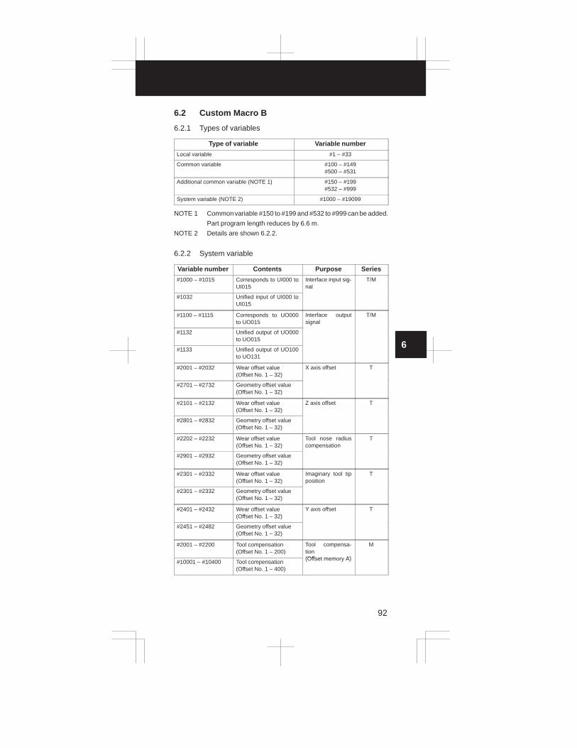
3
1
4
5
6
7
8
9
10
2
92
6.2 Custom Macro B
6.2.1 Types of variables
Type of variable Variable number
Local variable #1 – #33
Common variable #100 – #149#500 – #531
Additional common variable (NOTE 1) #150 – #199#532 – #999
System variable (NOTE 2) #1000 – #19099
NOTE 1 Common variable #150 to #199 and #532 to #999 can be added.
Part program length reduces by 6.6 m.
NOTE 2 Details are shown 6.2.2.
6.2.2 System variable
Variable number Contents Purpose Series
#1000 – #1015 Corresponds to UI000 toUI015
Interface input sig-nal
T/M
#1032 Unified input of UI000 toUI015
#1100 – #1115 Corresponds to UO000to UO015
Interface outputsignal
T/M
#1132 Unified output of UO000to UO015
#1133 Unified output of UO100to UO131
#2001 – #2032 Wear offset value(Offset No. 1 – 32)
X axis offset T
#2701 – #2732 Geometry offset value (Offset No. 1 – 32)
#2101 – #2132 Wear offset value (Offset No. 1 – 32)
Z axis offset T
#2801 – #2832 Geometry offset value (Offset No. 1 – 32)
#2202 – #2232 Wear offset value (Offset No. 1 – 32)
Tool nose radiuscompensation
T
#2901 – #2932 Geometry offset value(Offset No. 1 – 32)
#2301 – #2332 Wear offset value(Offset No. 1 – 32)
Imaginary tool tipposition
T
#2301 – #2332 Geometry offset value (Offset No. 1 – 32)
#2401 – #2432 Wear offset value (Offset No. 1 – 32)
Y axis offset T
#2451 – #2482 Geometry offset value(Offset No. 1 – 32)
#2001 – #2200 Tool compensation (Offset No. 1 – 200)
Tool compensa-tion (Offset memory A)
M
#10001 – #10400 Tool compensation (Offset No. 1 – 400)
(Offset memory A)

6. CUSTOM MACRO
93
Variable number SeriesPurposeContents
#2001 – #2200 Wear offset value (Offset No. 1 – 200)
Tool compensa-tion (Offset memory B)
M
#2201 – #2400 Geometry offset value (Offset No. 1 – 200)
(Offset memory B)
#10001 – #10400 Wear offset value (Offset No. 1 – 400)
#11001 – #11400 Geometry offset value(Offset No. 1 – 400)
#3000 Alarm T/M
#3001 Clock 1 (Unit: 1 ms) Clock T/M
#3002 Clock 2 (Unit: 1 hour)
#3003 Control of singleblock stop, waitsignal for FIN
T/M
#3004 Control of feed-hold, feedrateoverride, exactstop check
T/M
#3005 Setting T/M
#3011 Year, month, day Clock T/M
#3012 Hour, minute, second
#3901 No. of parts machined No. of parts T/M
#3902 No. of parts required
#4001 – #4022 G code (group 01 – 22) Model information T/M
#4102 B code
#4109 F code
#4111 H code
#4113 M code
#4114 Sequence number
#4115 Program number
#4119 S code
#4120 T code
#5001 – #5004 1st axis block end posi-tion
:4th axis block end posi-tion
Block end position(Workpiece coor-dinate)
T/M
#5021 – #5024 1st axis current position :
4th axis current position
Machine coordi-nate
T/M
#5041 – #5044 1st axis current position:
4th axis current position
Workpiece coordi-nate
T/M
#5061 – #5064 1st axis skip signal posi-tion
:4th axis skip signal posi-tion
Skip signal posi-tion (Workpiece coor-dinate)
T/M
#5081 – #5084 1st axis tool offset value:
4th axis tool offset value
Tool offset value T/M

3
1
4
5
6
7
8
9
10
2
94
Variable number SeriesPurposeContents
#5101 – #5104 1st axis servo positiondeviation
:4th axis servo positiondeviation
Servo positiondeviation
T/M
#2500#2600#2700#2800
External workpiece zeropoint offset value
1st axis 2nd axis 3rd axis4th axis
M
#2501#2601#2701#2801
G54 workpiece zeropoint offset value
1st axis 2nd axis 3rd axis4th axis
M
#2502#2602#2702#2802
G55 workpiece zeropoint offset value
1st axis 2nd axis 3rd axis4th axis
M
#2503#2603#2703#2803
G56 workpiece zeropoint offset value
1st axis 2nd axis 3rd axis4th axis
M
#2504#2604#2704#2804
G57 workpiece zeropoint offset value
1st axis 2nd axis 3rd axis4th axis
M
#2505#2605#2705#2805
G58 workpiece zeropoint offset value
1st axis 2nd axis 3rd axis4th axis
M
#2506#2606#2706#2806
G59 workpiece zeropoint offset value
1st axis 2nd axis 3rd axis4th axis
M
#2550
#2551
�
#2556
External workpiece zeropoint offset valueG54 (Workpiece coordi-nate system 1)
�
G59 (Workpiece coordi-nate system 6)
X axis T
#2650
#2651
�
#2656
External workpiece zeropoint offset valueG54 (Workpiece coordi-nate system 1)
�
G59 (Workpiece coordi-nate system 6)
Z axis T
#2750
#2751
�
#2756
External workpiece zeropoint offset valueG54 (Workpiece coordi-nate system 1)
�
G59 (Workpiece coordi-nate system 6)
C axis T
#2850
#2851
�
#2856
External workpiece zeropoint offset valueG54 (Workpiece coordi-nate system 1)
�
G59 (Workpiece coordi-nate system 6)
Y axis T

6. CUSTOM MACRO
95
Variable number SeriesPurposeContents
#7001 – #7004 G54 P1 workpiece zeropoint offset value
1st axis to 4th axis M
#7021 – #7024 G54 P2 workpiece zeropoint offset value
1st axis to 4th axis M
: : 1st axis to 4th axis
#7941 – #7944 G54 P48 workpiece zeropoint offset value
1st axis to 4th axis M
6.2.3 Argument assignment I/II
Correspondence
Table between Ar-
gument Assignment
I Addresses and
Macro Variables
Correspondence Table between Argument
Assignment II Addresses and Macro
Variables
ArgumentAssignmentI Addresses
MacroVariables
ArgumentAssignmentII Addresses
MacroVariables
ArgumentAssignmentII Addresses
MacroVariables
A # 1 A # 1 I7 #22
B # 2 B # 2 J7 #23
C # 3 C # 3 K7 #24
D # 7 I1 # 4 I8 #25
E # 8 J1 # 5 J8 #26
F # 9 K1 # 6 K8 #27
H #11 I2 # 7 I9 #28
I # 4 J2 # 8 J9 #29
J # 5 K2 # 9 K9 #30
K # 6 I3 #10 I10 #31
M #13 J3 #11 J10 #32
Q #17 K3 #12 K10 #33
R #18 I4 #13
S #19 J4 #14
T #20 K4 #15
U #21 I5 #16
V #22 J5 #17
W #23 K5 #18
X #24 I6 #19
Y #25 J6 #20
Z #26 K6 #21

3
1
4
5
6
7
8
9
10
2
96
6.2.4 Arithmetic commands
Purpose Expression Contents
Definition and sub-stitution of variables
#i=#j Definition, substitution
Addition arithmetic #i=#j+#k Sum
#i=#j–#k Subtraction
#i=#jOR#k Logical sum (at every bit of 32 bits)
#i=#jXOR#k Exclusive OR (at every bit of 32 bits)
Multiplication arith-ti
#i=#j*#k Productmetic #i=#j/#k Quotient
#i=#jAND#k Logical product (at every bit of 32 bits)
Functions #i=SIN [#j] Sine (degree unit)
#i=COS [#j] Cosine (degree unit)
#i=TAN [#j] Tangent (degree unit)
#i=ATAN [#j] Arctangent (degree unit)
#i=SQRT [#j]/[#k] Square root
#i=ABS [#j] Absolute value
#i=BIN [#j] Conversion from BCD to BIN
#i= BCD [#j] Conversion from BIN to BCD
#i=ROUND [#j] Rounding off
#i = FIX [#j] Discard fractions less than 1
#i = FUP [#j] Add 1 for fractions less than 1
Combination ofarithmetic opera-tions
— The above arithmetic operations andfunctions can be combined. The orderof priority in an arithmetic operation isfunction, multiplication arithmetic thenaddition arithmetic.
6.2.5 Control command
Purpose Expression Kind of operation
Conditionalb h
IF [<conditional expression>]GOTO
#j EQ #k (=)branch GOTO n
Branch to sequence number n.#j NE #k (�)
Branch to sequence number n.#j GT #k (>)
#j LT #k (<)
#jGE #k (�)
#j LE #k (�)
Iteration WHILE [<conditional expression>]DO
#j EQ #k (=)DO m(m = 1, 2, 3)
#j NE #k (�)(m = 1, 2, 3)If omitted conditional expression, #j GT #k (>)
blocks from DO m to END m areexecuted eternally
#j LT #k (<)executed eternally.
#jGE #k (�)
#j LE #k (�)

Main program
O–
G65P–
M99
O–
G65P–
M99
O–
G65P–
M99
…
Macro
(level 1)Macro
(level 4)
6. CUSTOM MACRO
97
6.2.6 Macro call
Name FormatProgram
No.Parame-ter No.
Remarks
Simple call G65P (program number)L (repetition count)<argument assignment>
Refer to6.2.3 forargument
iModal call G66P (program number);
L (repetition count)<argument assignment>
assign-ment.
Macro callby G code
Gxx <argument assign-ment>
9010:
9019
220:
229
Refer to6.2.3 forargument
Max. 10 G codes fromG01–G64 and G68–G255
gassign-ment. Set G or M
Macro callby M code
Mxx <argument assign-ment>
9020:
9029
230:
239
code thatcalls a pro-gram spe-ifi d iMax. 10 M codes from
M006 to M255
cified inthe param-eter.
Subpro-gram callby M code
Mxx; 900190029003
240241242
Displayedon pro-gramcheckscreen butno MF norM code is
t S tMax. 3 M codes fromM006–M255
sent. Setan M codethat calls asubpro-gram spe-cified bythe param-eter.
Subpro-gram callby T code
Tt; 9000 045#5 Calls sub-program9000. Tcode t isstored incommonvariable#149 asan argu-ment.
Multiplexcall
Can becalled upto 4 loopsincludingsimple calland modalcall.

3
1
4
5
6
7
8
9
10
2
98
6.2.7 Command range
Item Contents
Variables Local variable: #1–#33
Common variable: #100–#149, #500–#531
Additional common variable: #100–#199,
#500–#999
System variable: #1000–#19099
Value of variables Maximum value �1047
Minimum value �10–29
Constant in expression Maximum value �99999999
Minimum value �0.0000001
Decimal point possible
Arithmetic precision Decimal 8 digits
Macro call duplex Max. 4 loops
Iteration classification no. 1 to 3
Nesting Max. 5 loops
Nesting of subprograms Max. 4 loops(8 loops including macro calls)

7. STATUS DISPLAY BY SELF DIAGNOSTIC DISPLAY
99
7.1 CNC Internal Status Display
Self–diagnosis function displays
DGNOS number Displays
000 to 022States of signals supplied from the machine to the PMC. Ifthe system has no PMC, only 016 to 022 are valid
027Signal indicating when the pulse coder or position codermakes one turn.
048 to 086States of signals supplied from the PMC to the machine. Ifthe system has no PMC, only 048 to 053 are valid.
100 to 147States of signals supplied from the PMC to the CNC. If thesystem has no PMC, only 116 to 122 are valid.
148 to 199States of signals supplied from the CNC to the PMC. If thesystem has no PMC, only 148 to 153 are valid.
200 to 249 Window data from the PMC to the CNC.
250 to 299 Window data from the CNC to the PMC.
700, 701Internal state of the CNC. These are checked if a commandis not responded with.
712If a signal is turned off during automatic operation, thisDGNOS number indicates the reason.
720 to 727 States of digital servo alarms.
760 to 767770 to 777
States of serial pulse coder alarms.
800 to 807 Indicate a positional error for each axis.

3
1
4
5
6
7
8
9
10
2
100
CNC state display
If the CNC becomes inactive, but does not issue an alarm, press the DGNOSbutton to display the contents of DGNOS No. 700, 701, or 712. TheseDGNOS numbers show the state of the CNC.
0700 CSCT CITL COVZ CINP CDWL CMTN CFIN
When these bits are “1”, they mean:
CFIN: The M, S, or T function is being executed.
CMTN: A tool movement command is being executed during automaticoperation.
CDWL: A dwell command is being executed.
CINP: In position check is being made.
COVZ: The override is set to 0%.
CITL: The interlock signal is on.
CSCT: The spindle constant–speed reached signal is being awaited.
0701 CRST
CRST: An emergency stop, external reset, reset & rewind signal, or a resetbutton on the MDI panel is on.
0702 STP REST EMS RRW RSTB – – CSU
#7 #6 #5 #4 #3 #2 #1 #0 Cause
1 1 1 0 0 – – 1An emergency stop signal was sup-plied.
1 1 0 0 0 – – 0 An external reset signal was supplied.
1 1 0 1 0 – – 0 A reset & rewind signal was supplied.
1 1 0 0 1 – – 0 The reset button was pressed.
1 0 0 0 0 – – 1 A servo alarm occurred.
1 0 0 0 0 – – 0A feed hold signal was supplied, or themode was switched.
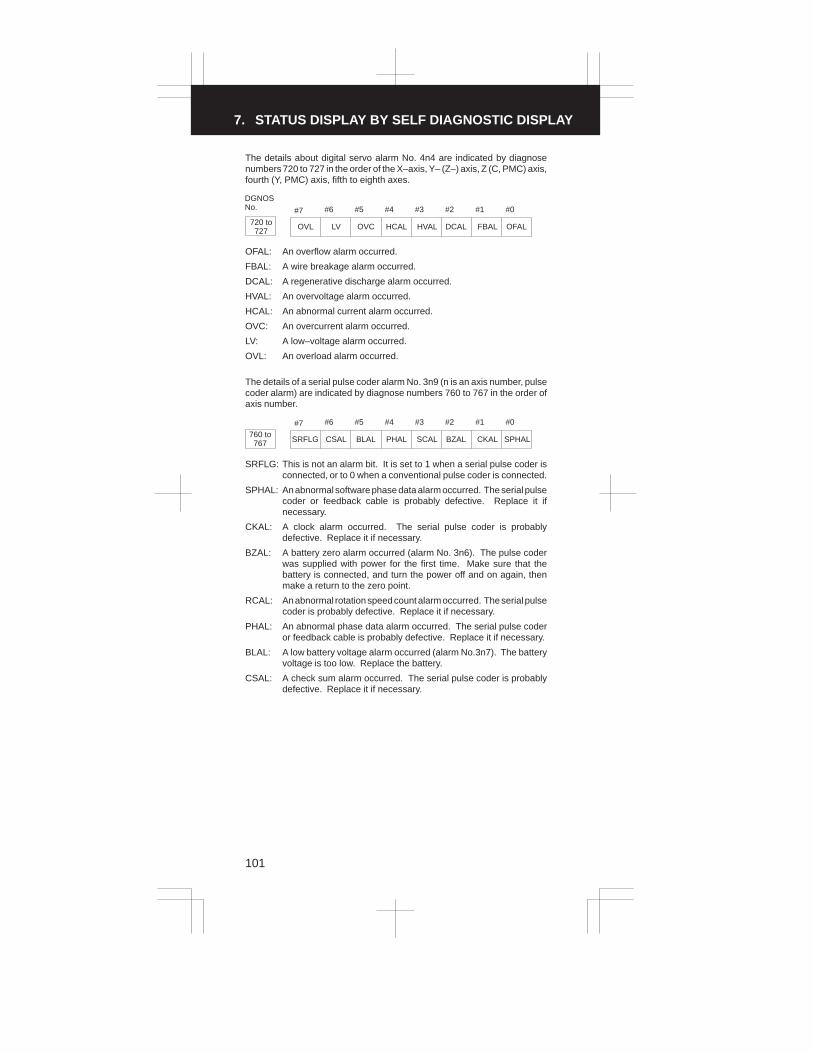
7. STATUS DISPLAY BY SELF DIAGNOSTIC DISPLAY
101
The details about digital servo alarm No. 4n4 are indicated by diagnosenumbers 720 to 727 in the order of the X–axis, Y– (Z–) axis, Z (C, PMC) axis,fourth (Y, PMC) axis, fifth to eighth axes.
DGNOSNo. #7 #6 #5 #4 #3 #2 #1 #0
720 to727 OVL LV OVC HCAL HVAL DCAL FBAL OFAL
OFAL: An overflow alarm occurred.
FBAL: A wire breakage alarm occurred.
DCAL: A regenerative discharge alarm occurred.
HVAL: An overvoltage alarm occurred.
HCAL: An abnormal current alarm occurred.
OVC: An overcurrent alarm occurred.
LV: A low–voltage alarm occurred.
OVL: An overload alarm occurred.
The details of a serial pulse coder alarm No. 3n9 (n is an axis number, pulsecoder alarm) are indicated by diagnose numbers 760 to 767 in the order ofaxis number.
#7 #6 #5 #4 #3 #2 #1 #0
760 to767 SRFLG CSAL BLAL PHAL SCAL BZAL CKAL SPHAL
SRFLG: This is not an alarm bit. It is set to 1 when a serial pulse coder isconnected, or to 0 when a conventional pulse coder is connected.
SPHAL: An abnormal software phase data alarm occurred. The serial pulsecoder or feedback cable is probably defective. Replace it ifnecessary.
CKAL: A clock alarm occurred. The serial pulse coder is probablydefective. Replace it if necessary.
BZAL: A battery zero alarm occurred (alarm No. 3n6). The pulse coderwas supplied with power for the first time. Make sure that thebattery is connected, and turn the power off and on again, thenmake a return to the zero point.
RCAL: An abnormal rotation speed count alarm occurred. The serial pulsecoder is probably defective. Replace it if necessary.
PHAL: An abnormal phase data alarm occurred. The serial pulse coderor feedback cable is probably defective. Replace it if necessary.
BLAL: A low battery voltage alarm occurred (alarm No.3n7). The batteryvoltage is too low. Replace the battery.
CSAL: A check sum alarm occurred. The serial pulse coder is probablydefective. Replace it if necessary.

3
1
4
5
6
7
8
9
10
2
102
The details of a serial pulse coder alarm No. 3n9 (n is an axis number,communication alarm) are indicated by diagnose numbers 770 to 777 in theorder of axis number.
#7 #6 #5 #4 #3 #2 #1 #0
770 to777 DTERR CRCERR STBERR
DTERR: A data error occurred.
CRCERR: A CRC error occurred.
STBERR: A stop bit error occurred.
The probable causes of the above errors include a defective pulse coder,feedback cable, and feedback receive circuit.
Replace the pulse coder, feedback cable, or NC axis board.
Position error display (DGNOS numbers 800 to 807)
800 to807 SVERRn (n is an axis number)
The amount of position error for axis n is indicated.
NOTE For the 0–TT, the positional deviation for the first and second axes
of the sub–tool post are indicated by 800 and 801 for the sub–tool
post.
Machine position relative to the reference position (DGNOS numbers 820 to 825)
820 to827 ABSMTn (n is an axis number.)
This machine position is also displayed on the position display page.
NOTE For the 0–TT, the machine position for the first and second axes of
the sub–tool post are indicated by 820 and 821 for the sub–tool
post.

7. STATUS DISPLAY BY SELF DIAGNOSTIC DISPLAY
103
7.2 I/O Signal Status Display between CNC and
PMC or Machine Tool
[For CNC without PMC]
Series 0 MT
X016 to X022
Y048 to Y053
[For CNC with PMC]
Series 0 MTF148 or later
PMC
X000 or later
Y048 or later
G100 or later
[For 0–TTC]
G100 or later
F148 or later
G1300 or later
F1348 or later
Toolpost #1
Toolpost #2
0–TTC
MTPMC–M
X000 or later
Y048 or later
7.2.1 I/O signal list
Symbol in column of T series or M series� : Available � : Available only 0–TTC� : Available only 0–GSC/0–GCC Space : Unavailable
Symbol Signal name T M PMC address
*+EDCX, *–EDCX ,*+EDCZ, *–EDCZ
External decelerationsignal
�
G138.0, G138.3,G138.1, G138.4
*+LX, *+LY, *+LZ,*–LX, *–LY, *–LZ
Over travel limit sig-nal
�
X020.0, X020.1,X020.2, X020.3,X020.4, X020.5
*+LZOver travel limit sig-nal
� X018.5
*+MITX, *+MITY,*+MITZ, *+MIT4,*–MITX, *–MITY,*–MITZ, *–MIT4
Interlock signal foreach axis and direc-tion
�
G142.0, G142.1,G142.2, G142.3,G142.4, G142.5,G142.6, G142.7
*–EDCX, *+EDCX,*–EDCY, *+EDCY,*–EDCZ, *+EDCZ
External decelerationsignal
�
G138.3, G138.0,G138.4, G138.1,G138.5, G138.2
*ABSMManual absolute sig-nal
� � G127.2
*AOV16, *AOV32,*AOV64, *AOV128 1% step override sig-
�
G116.4, G116.5,G116.6, G117.6
*AOVR16, *AOVR32,*AOVR64, *AOVR128
gnal
� G140.4, G140.5,G140.6, G140.7
*BECLPB–axis clampcompletion signal
� G143.7
*BEUCPB–axis unclampcompletion signal
� G143.6
*DECX, *DECY,*DECZ, *DEC4,
Deceleration signalfor reference positionreturn
�
X016.5, X017.5,X018.5, X019.5

3
1
4
5
6
7
8
9
10
2
104
Symbol PMC addressMTSignal name
*DECX, *DECZ,*DEC3, *DEC4,
Deceleration signalfor reference positionreturn
� X016.5, X017.5,X018.5, X019.5
*EAXSLControl axis selectionstatus signal (PMCaxis control)
� � F188.7
*ESP, *ESPEmergency stop sig-nal
� � X021.4, G121.4
*ESPA, *ESPBEmergency stop sig-nal of spindle
� G230.1, G234.1
*FLWU Follow–up signal � � G104.5
*ILK Interlock signal � G117.0
*ITX, *ITY, *ITZ, *IT4Interlock signal foreach axis
�
G128.0, G128.1,G128.2, G128.3
*LDSP Ladder display signal � � G119.0
*OV1, *OV2, *OV4,*OV8
Override signal � �
G121.0, G121.1,G121.2, G121.3
*OV1E, *OV2E,*OV4E, *OV8E,*OV16E
Feedrate overridesignal (PMC axiscontrol )
� �
G147.0, G147.1,G147.2, G147.3,G147.4
*RILKHigh–speed interlocksignal
� X008.5
*SCPFSpindle clampcompletion signal
� G123.5
*SPAutomatic operationhold signal
� � G121.5
*SSTP Spindle stop signal � � G120.6
*SSTP1, *SSTP2,*SSTP3
Individual spindlestop signal
� G145.3, G145.4,G145.5
*SUCPFSpindle unclampcompletion signal
� G123.4
+3O , –3O Jog feed axis selectsignal (software oper-
� F177.4, F177.5
+4O, –4Osignal (software o er-ator’s panel signal) � � F177.6, F177.7
+4, –4Feed axis directionselect signal
� � G119.2, G119.3
+LMX, +LMY, +LMZ,–LMX, –LMY, –LMZ
Software limit exter-nal setting
�
G129.0, G129.1,G129.2, G129.3,G129.4, G129.5
+MIT1, –MIT1, +MIT2,–MIT2
Interlock signal foreach axis direction
� X008.2, X008.3X008.4, X008.5
+X, –X, +Z, –Z
Feed axis direction
� G116.2, G116.3,G117.2, G117.3
+X, –X, –Y, +Y, –Z, +Z
Feed axis directionselect signal
�
G116.2, G116.3,G117.3, G117.2,G118.3, G118.2
+XO, –XO, +YO, –YO,+ZO, –ZO Jog feed axis select
signal (software oper-
�
F177.0, F177.1,F177.2, F177.3,F177.4, F177.5
+XO, –XO, +ZO, –ZO
g (ator’s panel signal)
� F177.0, F177.1,F177.2, F177.3
4NG 4 axes disable signal � X004.7
AFLMiscellaneous func-tion lock signal
� � G103.7
AL CNC alarm signal � � F149.0
ALMA, ALMB Spindle alarm signal � F281.0, F285.0

7. STATUS DISPLAY BY SELF DIAGNOSTIC DISPLAY
105
Symbol PMC addressMTSignal name
AR0 to AR15Actual spindle speedsignal
� F158.0 to F159.7
ARSTA, ARSTB Alarm reset signal � � G230.0, G234.0
B0 to B31 2nd auxiliary function � F276.0 to F279.7
B11 to B38y
signal � F155.0 to F154.3
BAL Battery alarm � � F149.2
BAL1 to BAL4, BAL7,BAL8 Absolute pulse coder
� F156.0 to F156.5
BAL1 to BAL4, BAL7,BAL8
battery alarm � F159.0 to F159.5
BCLP B axis clamp signal � F188.3
BDT1, BDT2 to BDT9Optional block skipsignal
� �
G116.0, G141.0 toG141.7
BDTOOptional block skipsignal (software oper-ator’s panel signal)
� � F176.4
BF B code strobe signal � F150.7
BF1, BF2 B code strobe signal � F150.7, F150.6
BFIN2nd auxiliary functioncompletion signal
� G115.7
BFIN1, BFIN22nd auxiliary functioncompletion signal
� G115.7, G115.6
BGEACTBackground busy sig-nal
� � F180.4
BOFFInterference check in-valid alarm signal
� F180.6
BUCLPB axis unclamp sig-nal
� F188.2
CDZ Chamfering signal � G126.7
CFINA, CFINBSpindle switchcompletion signal
� � F282.1, F286.1
CHPA, CHPBPower line switch sig-nal
� � F282.0, F286.0
CKGRP Drawing signal � � F164.5
COFF Cs contour control � G123.0
CON change signal � G123.7
COSPSpindle commandsignal
� F180.5
CTH1A, CTH2AClutch/gear signal(serial spindle)
� � G229.3, G229.2
CUT Cutting feed signal � � F188.6
DENDistribution end sig-nal
� � F149.3
DEN2Passed point outputsignal
� F149.6
DLKRenewal disable sig-nal of relative coordi-nate
� � G127.6
DMMCDNC signal by datafrom MMC
� � G128.7
DNCIDNC operation selectsignal
� � G127.5
DRN Dry run signal � G118.7

3
1
4
5
6
7
8
9
10
2
106
Symbol PMC addressMTSignal name
DRNEDry run signal (PMCaxis control )
� � G147.7
DRNODry run signal (soft-ware operator’s panelsignal)
� � F176.7
DSTManual data inputstart signal
� � F150.5
EA0 to EA6Address signal (forexternal data input)
� G102.0 to G102.6
EAX1 to EAX8Control axis selectsignal (PMC axiscontrol )
� � G144.0 to G144.5
EBSYA, EBSYBCommand readcompletion signal(PMC axis control )
� � F270.7, F273.7
EBUFA, EBUFBCommand read signal(PMC axis control )
� � G210.7, G218.7
EC0A to EC7A, EC0Bto EC7B
Axis control com-mand signal (PMCaxis control )
� �
G211.0 to G211.7,G219.0 to G219.7
ECKZA, ECZKBFollowing zerochecking signal(PMCaxis control )
� � F270.1, F273.1
ECLRA, ECLRBReset signal (PMCaxis control )
� � G210.6, G218.6
ED0 to ED15Data signal (for exter-nal data input)
� � G100.0 to G101.7
EDENA, EDENBAuxiliary functionexecuting signal(PMC axis control )
� � F270.3, F273.3
EFExternal operationsignal
� F150.0
EFDExternal operationsignal for high–speedinterface
� F150.1
EFINExternal operationcompletion signal forhigh–speed interface
� G115.1
EFINA, EFINBAuxiliary functioncompletion signal(PMC axis control )
� � G210.0, G218.0
EGENA, EGENBAxis moving signal(PMC axis control )
� � F270.4, F273.4
EIALA, EIALBAlarm signal (PMCaxis control )
� � F270.2, F273.2
EID0A to EID31A,EID0B to EID31B
Axis control data sig-nal (PMC axis con-trol)
� �
G214.0 to G217.7,G222.0<G225.7
EIF0A to EIF15A,EIF0B to EIF15B
Axis control feedratesignal (PMC axiscontrol)
� �
G212.0 to G213.7,G220.0 to G221.7
EINPA, EINPBIn–position signal(PMC axis control)
� � F270.0, F273.0
EM11A to EM28A,EM11B to EM28B
Auxiliary functioncode signal (PMCaxis control)
� �
F272.0 to F272.7,F275.0 to F275.7
EMFA, EMFBAuxiliary functionstrobe signal (PMCaxis control)
� � F271.0, F274.0

7. STATUS DISPLAY BY SELF DIAGNOSTIC DISPLAY
107
Symbol PMC addressMTSignal name
EMSBKA, EMSBKBBlock stop disablesignal (PMC axiscontrol)
� � F211.0, G219.0
ENB � � F149.4
ENB2, ENB3Spindle enable signal
� F149.4, F164.2,F164.3
ENBKYExternal key inputmode select signal
� � G134.0
EOTNA, EOTNBNegative–directionovertravel signal(PMC axis control)
� � F270.6, F273.6
EOTPA, EOTPBPositive–directionovertravel signal(PMC axis control)
� � F270.5, F273.5
EOV0Override 0% signal(PMC axis control )
� � F188.5
ERENDRead completion sig-nal (for external datainput)
� � F160.0
ERS External reset signal � � G121.7
ESBKA, ESBKBBlock stop signal(PMC axis control )
� � G210.3, G218.3
ESENDSearch completionsignal (for externaldata input)
� � F160.1
ESKIPSkip signal (PMCaxis control )
� X008.6
ESOFA, ESOFBServo off signal(PMC axis control )
� � G210.4, G218.4
ESRSYCSimple spindle syn-chronous control sig-nal
� � G104.4
ESTBRead signal (for ex-ternal data input)
� � G102.7
ESTPA, ESTPBAxis control tempo-rary stop signal (PMCaxis control )
� � G210.5, G218.5
EXLMZStored stroke limitselect signal
� � G129.6
EXRDExternal read startsignal
� � G134.1
EXSTPExternal read/punchstop signal
� � G134.2
EXWTExternal punch startsignal
� � G134.3
F1DF1–digit feed selectsignal
� G140.7
FINM, S, T, B functioncompletion signal
� � G120.3
FSCSLCs contour controlchange completionsignal
� F178.1
FSPPHSerial spindle phasesynchronous comple-tion signal
� � F178.3
FSPSYSerial spindle syn-chronous mode sig-nal
� � F178.2

3
1
4
5
6
7
8
9
10
2
108
Symbol PMC addressMTSignal name
FXSTCanned cycle startsignal
� F161.4
GOQSMOffset write modesignal
� G132.7
GR1, GR2Gear select signal
� G118.2, G118.3
GR1, GR2Gear select signal
� G123.2, G123.3
GR1O, GR2O, GR3O Gear select signal �
G152.0, G152.1,G152.2
GR212nd spindle gear se-lect signal
� G145.6
GR313rd spindle gear se-lect signal
� G145.7
GWLFAutomatic grindingwheel diameter com-pensation
� F165.3
H4Osoftware operator’spanel signal
� F174.7
HIX, HIY, HIZ, HI4 Manual handle inter-ruption axis select
�
G126.0, G126.1,G126.2, G126.3
HIX, HIZ, HI3, HI4
ru tion axis selectsignal �
G126.0, G126.1,G126.2, G126.3
HX, HY, HZ, H4Handle feed axis se-
�
G116.7, G117.7,G118.7, G119.7
HX, HZ, H3, H4lect signal
� G116.7, G117.7,G118.7, G119.7
HXO, HYO, HZO Manual pulse genera-tor feed axis select
�
F174.4, F174.5,F174.6
HXO, HZO, H3O, H4Osignal (software oper-ator’s panel signal) �
F174.4, F174.5,F174.6, F174.7
IGNVRY V–READY check sig- � G127.0
IGNVRYg
nal � G123.0
INDXA, INDXBSpindle orientationstop position changesignal
� G231.0, G235.0
INFDInfeed control cuttingstart signal
� G237.6
INHKYKey input disable sig-nal
� � F180.0
INP1 to INP4 In–position signal � � F184.0 to F184.3
ITX, ITZ, IT3, IT4Interlock signal foreach axis
� G128.0, G128.1,G128.2, G128.3
JOV1 to JOV8Jog feedrate overridesignal
� G104.0 to G104.3
JV1O, JV2O, JV4O,JV8O
Jog feedrate overridesignal (software oper-ator’s panel signal)
� F175.0, F175.1,F175.2, F175.3
JV1O to JV8OFeedrate overridesignal (software oper-ator’s panel signal)
� F175.0 to F175.3

7. STATUS DISPLAY BY SELF DIAGNOSTIC DISPLAY
109
Symbol PMC addressMTSignal name
K0, S, K1, U, K2, W,K3, R, K4, X, K5, Z,K6, F, K7, 0, K8, N, K9,G, KA, C, KALARM,KALTER, KCAN,KCUS↑ , KCUS↓ , KDELET, KDGNOS,KEOB
�
G106.0, G106.1,G106.2, G106.3,G106.4, G106.5,G106.6, G106.7,G107.0, G107.1,G107.5, G109.5,G108.0, G110.7,G110.1, G110.0,G108.2, G109.4,G107.7
KFF, KFFE, KFGB,KFI,, KFK%, KFL+,KFM., KFN), KFO (,KFRC, KFS=, KFT*,KFUV, KFWH, KFXY,KFZJ, KH, I, K
�
G114.3, G114.2,G113.2, G114.0,G114.1, G114.7,G114.4, G113.1,G113.0, G113.3,G114.5, G114.6,G113.6, G113.7,G113.4, G113.5,G107.6
KINPUT, KINSRT, KM,–, KP, Q, KPAGE ↑ ,KPAGE ↓ , KPARAM,KPOS, KPROGRM,KRESET, KS1, KS2,KS3, KS4, KS5, KSL,KSR, KSTART, KT,.,KXZ, KXZ
Key signal
�
G108.3, G108.1,G107.2, G107.4,G110.3, G110.2,G109.3, G109.0,G109.1, G111.7,G112.6, G112.5,G112.4, G112.3,G112.2, G112.7,G112.1, G108.4,G107.3, G142.7,G110.4
K0, S, K1, H, K2, F,K3, R, K4, X, K5, Y,K6, Z, K7, 0, K8, N,K9, G, KALARM,KALTER, KB, K4, D,KCAN, KCUS↑ ,KCUS↓ , KDELET,KDGNOS, KEOB, / , .
Key signal
�
G106.0, G106.1,G106.2, G106.3,G106.4, G106.5,G106.6, G106.7,G107.0, G107.1,G109.5, G108.0,G107.5, G110.7,G110.1, G110.0,G108.2, G109.4,G107.7
KF4TH, KFF, KFF%,KFGE, KFI,, KFJA,KFL+, KFM., KFN),KFO (, KFRC, KFS=,KFT*, KFXU, KFXW,KFYV, KH, J, K, KIN-PUT, KINSRT, KM, –,KOFSET, KP, Q, L,KPAGE↑ , KPAGE↓ ,KPARAM, KPOS,KPROGRM, KRESET,KS1, KS2, KS3, KS4,KS5, KSL, KSR,KSTART, KT,., KXY,KYZ, KZX
�
G113.7, G114.3,G114.2, G113.2,G114.0, G114.1,G114.7, G114.4,G113.1, G113.0,G113.3, G114.5,G114.6, G113.4,G113.6, G113.5,G107.6, G108.3,G108.1, G107.2,G109.2, G107.4,G110.3, G110.2,G109.3, G109.0,G109.1, G111.7,G112.6, G112.5,G112.4, G112.3,G112.2, G112.7,G112.1, G108.4,G107.3, G110.4,G110.6, G110.5
KEYProgram protect sig-nal
� � G122.3
KEYOProgram protect sig-nal (software opera-tor’s panel signal)
� � F178.5

3
1
4
5
6
7
8
9
10
2
110
Symbol PMC addressMTSignal name
KILPLUSPosition coder returndirection select signal
� � G105.6
KOFSET External key input � G109.2
LDT1A, LDT1B,LDT2A, LDT2B
Load detection signal � �
F281.4, F285.4,F281.5, F285.5
M00, M01, M02, M30 M decode signal �
F154.7, F154.6,F154.5, F154.4
M11, M12, M14, M18,M21, M22, M24, M28,M31, M32, M34, M38
Miscellaneous func-tion code signal
� �
F151.0, F151.1,F151.2, F151.3,F151.4, F151.5,F151.6, F151.7,F157.0, F157.1,F157.2, F157.3
M211, M212, M214,M218, M221, M222,M224, M228, M231,M232, M234, M238
2nd M function codesignal
� �
F193.0, F193.1,F193.2, F193.3,F193.4, F193.5,F193.6, F193.7,F194.0, F194.1,F194.2, F194.3
M311, M312, M314,M318, M321, M322,M324, M328, M331,M332, M334, M338
3rd M function codesignal
� �
F194.4, F194.5,F194.6, F194.7,F195.0, F195.1,F195.2, F195.3,F195.4, F195.5,F195.6, F195.7
MA CNC ready signal � � F149.7
MCFNA, MCFNBPower line switchcompletion signal
� � G230.3, G234.3
MD1, MD2, MD4 Mode select signal � �
G122.0, G122.1,G122.2
MD1O, MD2O, MD4OMode select signal(software operator’spanel signal)
� �
F174.0, F174.1,F174.2
MFMiscellaneous func-tion strobe signal
� F150.0
MF2, MF32nd or 3rd M functionstrobe signal
� F157.4, F157.5
MFINMiscellaneous func-tion completion sig-nal
� � G115.0
MFIN22nd M functioncompletion signal
� � G134.4
MFIN33rd M functioncompletion signal
� � G134.5
MINP External program in- � G120.0
MINPg
put start signal � G117.0
MIRX, MIRY, MIR4Mirror image signal
�
G127.0, G127.1,G127.7
MIX, MIZg g
� G120.0, G127.1
MLKAll–axis machinelock signal
� � G117.1
MLKOMachine lock signal(software operator’spanel signal)
� � F176.6
MMI1, MMI2Mirror image check
� � F158.0, F158.1
MMI1, MMI2, MMI4Mirror image checksignal �
F158.0, F158.1,F158.3,

7. STATUS DISPLAY BY SELF DIAGNOSTIC DISPLAY
111
Symbol PMC addressMTSignal name
MP1, MP2 Manual handle feed � G118.0, G119.0
MP1, MP2 amount select signal � G120.0, G120.1
MP1O, MP2O
Select of magnifica-tion of manual pulsegenerator (softwareoperator’s panel sig-nal)
� � F175.6, F175.7
MRDYA, MRDYBMachine ready signal(serial spindle)
� � G229.7, G233.7
MVX, MVY, MV3, MV4Axis moving signal
� F148.4 to F148.7
MVX, MVY, MVZ, MV4Axis moving signal
� F148.4 to F148.7
NOWT No–wait signal � G133.1
NOZAGC Angular axis controlZ axis offset moving
� G133.6
NOZAGCZ axis offset movingsignal � G237.5
NRROA, NRROB
Short–distant move-ment command whilechanging the orienta-tion stop position sig-nal
� G231.2, G235.2
OFN0, OFN1, OFN2,OFN3, OFN4
Tool offset numberselect signal of tooloffset measurementdirect input
� G132.0, G132.1,G132.2, G132.3,G132.4
OPAutomatic operationsignal
� � F148.7
ORARA, ORARBSpindle orientationcompletion signal
� � F281.7, F285.7
ORCMA, ORCMBOrientation commandsignal
� � G229.6, G233.6
OUT0 to OUT7Software operator’spanel general–pur-pose switch signal
� � F171.0 to F171.7
OV1O, OV2O, OV4O,OV8O
Feedrate overridesignal (software oper-ator’s panel signal)
� �
F176.0, F176.1,F176.2, F176.3
OVCOverride cancel sig-nal
� � G126.4
OVCEPMC axis overridecancel signal
� � G147.5
PC2SLC2nd position coderselect signal
� G146.7
PCFNA, PCFNBOutput switchingcompletion signal
� �
F280.3, F282.3,F282.3, F286.3
PCHPA, PCHPBOutput switching sig-nal
� �
F280.2, F282.2,F282.2, F286.2
PK1M, PK2M, PK3M,PK4M, PK5M, PK6M
Synchronous controlparking signal
� G238.0, G238.1,G238.2, G238.3,G238.4, G238.5
PKESS11st spindle parkingsignal
� � G138.6
PKESS22nd spindle parkingsignal
� � G138.7
PLCRVONPosition coder returncontrol signal
� � G105.7
PN1, PN2, PN4, PN8Workpiece numbersearch signal
� �
G122.4, G122.5,G122.6, G122.7

3
1
4
5
6
7
8
9
10
2
112
Symbol PMC addressMTSignal name
PRC Position record signal � G103.6
PRGDPLProgram screen dis-play signal
� � F180.1
PRTSFRequired parts countreached signal
� � F164.7
PSW01 to PSW10 Position switch signal � � F190, F191.0, F191.1
PSYNPolygon machiningin–progress signal
� F160.7
PX0 to PX7, PZ0 toPZ7
Position signal output � F165.0 to F165.7,F167.0 to F167.7
R01O to R12O S12–bit code signal � � F172.0 to F173.3
RCHA, RCHBPower line statuscheck signal
� � G230.7, G234.7
RGSPM, RGSPPSpindle rotationdirection signal
� F165.1, F165.0
RGTAP, RGTPNRigid tapping signal
� G135.0, G123.1
RGTPNRigid tapping signal
� � G123.1
RGTSP1, RGTSP2Rigid tapping spindleselect signal
� � G061.4, G061.5
RLSOTSoftware limit exter-nal setting
� G129.7
RMTDI0 to RMTDI7Remote buffer inputsignal
� � G239.0 to G239.7
RMTDO0 to RMTDO7 Remote buffer output � F290.0 to F290.7
RMTDO0 to RMTDO7 signal � F289.0 to F289.7
RO1I to R12I, RO1I2to R12I2, RO1I3 toR12I3
Motor speed com-mand spindle inputsignal
� �
G124.0 to G125.3,G106.0 to G107.3,G108.0 to G109.3
ROTAA, ROTAB
Spindle rotationdirection commandsignal while changingthe orientation stopposition
� � G231.1, G235.1
ROV1, ROV2Rapid traverse over-ride signal
� G116.7, G117.7
ROV1D, ROV2D,ROV3D
Rapid traverse over-ride B signal
� G116.4, G116.5,G116.6
ROV1E, ROV2EPMC axis rapid tra-verse override signal
� � G146.0, G146.1
ROV1O, ROV2O
Rapid traverse over-ride signal (softwareoperator’s panel sig-nal)
� � F175.4, F175.5
RPALMRead/punch alarmsignal
� � F180.3
RPBSYRead/punch in–prog-ress signal
� � F180.2
RRW Rewind signal � � G104.6
RSLA, RSLBOutput switch requestsignal
� � G230.6, G234.6
RSMAXSerial spindle syn-chronous polygonsignal
� F189.7
RST Reset signal � � F149.1

7. STATUS DISPLAY BY SELF DIAGNOSTIC DISPLAY
113
Symbol PMC addressMTSignal name
RTManual rapid traverseselect signal
� � G121.6
RTEManual rapid traverseselect signal (PMCaxis control )
� G147.6
RTO
Jog rapid traverse se-lect signal (softwareoperator’s panel sig-nal)
� � F178.6
RWD Rewinding signal � � F164.6
S11, S12, S14, S18,S21, S22, S24, S28
Spindle function codesignal
� �
F152.0, F152.1,F152.2, F152.3,F152.4, F152.5,F152.6, F152.7
SAServo ready comple-tion signal
� � F148.6
SARSpindle speedreached signal
� � G120.4
SARA, SARB Speed reached sig- � F281.3, F285.3
SARA, SARBg
nal � F281.3, F285.3
SBK Single block signal � � G116.1
SBKOSingle block signal(software operator’spanel signal)
� � F176.5
SBRTSpindle synchronouspolygon mode signalfor 0–TTC
� G146.6
SCLP Spindle clamp signal � F164.0
SDTA, SDTB Speed detection sig- � F281.2, F285.2
SDTA, SDTBg
nal � F281.2, F285.2
SFSpindle functionstrobe signal
� � F150.2
SFINSpindle functioncompletion signal
� � G115.2
SFRA, SFRBSpindle CW com-mand signal
� � G229.5, G233.5
SGN, SGN2, SGN3Spindle motor com-mand polarity selectsignal
� �
G125.5, G107.5,G109.5
SHA00 to SHA11
1st spindle orienta-tion external stopposition commandsignal
� �
G110.0 to G110.7,G111.0 to G111.3
SHB00 to SHB11
2nd spindle orienta-tion external stopposition commandsignal
� �
G112.0 to G112.7,G113.0 to G113.3
SIGNSpindle analog volt-age control signal
� G125.7
SIND, SIND2, SIND3Spindle motor speedcommand signal
� G125.7, G107.7,G109.7
SKIP � X008.7
SKIP2, SKIP3, SKIP4Skip signal
� �
X008.2, X008.3,X008.4
SLHZ0, SLHZ1Z axis manual handleselect signal
� G133.0, G133.1

3
1
4
5
6
7
8
9
10
2
114
Symbol PMC addressMTSignal name
SLPCA, SLPCBSpindle return selectsignal
� G1333.2, G1333.3
SLSPA, SLSPBSpindle analog volt-age output select sig-nal
� G133.2, G133.3
SMZ Error detect signal � G126.6
SOCNA, SOCNBSoft start /stop cancelsignal
� � G230.4, G234.4
SORSpindle orientationsignal
� � G120.5
SPA, SPB, SPCSpindle speed over-
�
G103.3, G103.4,G103.5
SPA, SPB, SPC, SPDride signal
� G103.3, G103.4,G103.5, G103.2
SPALSpindle fluctuationdetection alarm sig-nal
� F154.0
SPDS1, SPDS2,SPDS3, SPDS4
Signal by axis mov-ing speed
�
F189.0, F189.1,F189.2, F189.3
SPLAutomatic operationhalt signal
� � F148.4
SPOFeed hold signal(software operator’spanel signal)
� � F178.7
SPPHSSerial spindle phasesynchronous modesignal
� � G146.3
SPSLA, SPSLB Spindle select signal � � G230.2, G234.2
SPSTPSpindle stop comple-tion signal
� G123.6
SPSYCSerial spindle syn-chronous mode sig-nal
� � G146.2
SRNProgram restart sig-nal
� � G103.0
SRNMVProgram restart un-der way signal
� � F188.4
SRVA, SRVBSpindle CCW com-mand signal
� � G229.4, G233.4
SSIN, SSIN2, SSIN3Spindle motor com-mand polarity selectsignal
� �
G125.6, G107.6,G109.6
SSTA, SSTB Speed zero detection � F281.1, F285.1
SSTA, SSTB signal � F281.1, F285.1
STAutomatic operationstart lamp signal
� � G120.2
STLAutomatic operationstart signal
� � F148.5
STLK Start lock signal � G120.1
STRDInput and run simulta-neous mode selectsignal
� G140.5
STWDOutput and run simul-taneous mode selectsignal
� G140.6
SUCLPSpindle unclampcompletion signal
� F164.1

7. STATUS DISPLAY BY SELF DIAGNOSTIC DISPLAY
115
Symbol PMC addressMTSignal name
SVFX, SVFY, SVFZ,SVF4
Servo off signal
�
G105.0, G105.1,G105.2, G105.3
SVFX, SVFZ, SVF3,SVF4
Servo off signal�
G105.0, G105.1,G105.2, G105.3
SWS1, SWS2, SWS3 Spindle select signal � G145.0, G145.1,G145.2
SYCALSpindle synchronouscontrol alarm signal
� F178.4
SYCALSynchronous errordetection signal
� F178.4
SYN1M, SYN2M,SYN3M, SYN4M,SYN5M, SYN6M
Synchronous controlstart signal
� G237.0, G237.1,G237.2, G237.3,G237.4, G237.5
SYN1OM, SYN2OM,SYN3OM, SYN4OM,SYN5OM, SYN6OM
Axis recompositionsignal
� F189.0, F189.1,F189.2, F189.3,F189.4, F189.5
SYNALServo axis synchro-nous alarm signal
� F192.7
SYNC4Simple synchronousaxis select signal
� G237.3
SYNCJSimple synchronouscontrol signal
� G133.6
SYNCX, SYNCZ,SYNC3, SYNC4
Simple synchronousaxis select signal
� G237.0 to G237.3
T11 to T28 Tool function code � F153.0 to F153.7
T11 to T48 signal � F153.0 to F156.7
TALInterference alarmsignal
� F180.7
TAP Tapping signal � � F149.5
TFTool function strobesignal
� � F150.3
TFINTool function comple-tion signal
� � G115.3
THRDThread cutting in–progress signal
� F188.3
TL01, TL02, TL04,TL08, TL16, TL32,TL64
Tool group numbersignal
� �
G139.0, G139.1,G139.2, G139.3,G139.4, G139.5,G139.6
TLCH Tool change signal � � F188.0
TLCHBTool life reached sig-nal
� F192.2
TLCHEAll–tool life reachedsignal
� F192.1
TLCHIIndividual toolchange signal
� F192.0
TLMA, TLMBTorque limit signal
� � F281.6, F285.6
TLMA, TLMBTorque limit signal
� F281.6, F285.6
TLMHA, TLMHBHigh–speed torquelimit signal
� � G229.1, G233.1
TLMLA, TLMLBLow speed torquelimit signal
� � G229.0, G233.0
TLNWNew tool select sig-nal
� � F188.1

3
1
4
5
6
7
8
9
10
2
116
Symbol PMC addressMTSignal name
TLRSTTool change resetsignal
� � G139.7
TLRSTIIndividual toolchange reset signal
� G140.4
TLSKP Tool skip signal � � G140.0
TNFSTool offset numberautomatic select dis-able signal
� G132.5
TORQ1, TORQ2,TORQ3, TORQ4,TORQ7, TORQ8
Torque limit reachedsignal
� F170.0, F170.1,F170.2, F170.3,F170.4, F170.5
TRT2, TRT2PCTool post select sig-nal
� X018.3, G133.0
UI000 to UI015Input signal for cus-tom macro
� � G130.0 to G131.7
UINTInterrupt signal forcustom macro
� � G140.3
UO000 to UO015,UO100 to UO131
Output signal for cus-tom macro
� �
F162.0 to F163.7,F196.0 to F199.7
WATO Waiting signal � F160.6
WNRQWindow request sig-nal
� � G200.0
WNANSWindow completionsignal
� � F250.0
WNWRT Window write signal � � G200.1
WNERR Window error signal � � F250.1
WOQSM
Workpiece coordi-nate system shift val-ue write mode selectsignal
� G132.6
WOSETWorkpiece coordi-nate system shift val-ue write signal
� G133.7
XAE, YAE, ZAEMeasuring positionreached signal
�
X008.0, X008.1,X008.2
XAE, ZAEMeasuring positionreached signal
� X008.0, X008.1
XAESAutomatic tool offsetfunction signal
� X040.0
ZAESAutomatic tool offsetfunction signal
� X040.1
ZNGZ axis command can-cel signal
� G103.6
ZP2X, ZP2Y, ZP2Z,ZP24 2nd reference posi-
tion return completion
�
F161.0, F161.1,F161.2, F161.3,F166.6, F166.7
ZP2X, ZP2Z, ZP23,ZP24
tion return com letionsignal
� F161.0, F161.1,F161.2, F161.3,F166.6, F166.7
ZP3X, ZP3Y, ZP3Z,ZP34 3rd reference position
return completion sig-
�
F169.0, F169.1,F169.2, F169.3,F166.0, F166.1
ZP3X, ZP3Z, ZP33,ZP34
return com letion sig-nal
� F169.0, F169.1,F169.2, F169.3,F166.0, F166.1

7. STATUS DISPLAY BY SELF DIAGNOSTIC DISPLAY
117
Symbol PMC addressMTSignal name
ZP4X, ZP4Y, ZP4Z,ZP44 4th reference position
return completion sig-
�
F169.4, F169.5,F169.6, F169.7,F166.2, F166.3
ZP4X, ZP4Z, ZP43,ZP44
return com letion sig-nal
� F169.4, F169.5,F169.6, F169.7,F166.2, F166.3
ZPX, ZPY, ZPZ, ZP4Reference positionreturn completion sig-
�
F148.0, F148.1,F148.2, F148.3,F166.4, F166.5
ZPX, ZPZ, ZP3, ZP4
return com letion sig-nal
� F148.0, F148.1,F148.2, F148.3,F166.4, F166.5
ZRFX, ZRFY, ZRFZ,ZRF4 Reference position
�
F168.0, F168.1,F168.2, F168.3
ZRFX, ZRFZ, ZRF3,ZRF4
establishment signal�
F168.0, F168.1,F168.2, F168.3
ZRNManual referenceposition return selectsignal
� � G120.7
ZRNOMode select signal(software operator’spanel signal)
� � F174.3

3
1
4
5
6
7
8
9
10
2
Address list (for M series)
118
7.2.2 Address list
Address list (for M series)
MT→PMC
#7 #6 #5 #4 #3 #2 #1 #0
X004 4NG
X008 SKIP ESKIP *RILK ZAE YAE XAE
X016 *DECX *DEC5S *DEC7
X017 *DECY *DEC6S *DEC8
X018 *DECZ
X019 *DEC4
X020 *– LZ *– LY *– LX *+ LZ *+ LY *+ LX
X021 *ESP
PMC→CNC
#7 #6 #5 #4 #3 #2 #1 #0
G100 ED7 ED6 ED5 ED4 ED3 ED2 ED1 ED0
G101 ED15 ED14 ED13 ED12 ED11 ED10 ED09 ED08
G102 ESTB EA6 EA5 EA4 EA3 EA2 EA1 EA0
G103 AFL ZNG SPC SPB SPA SRN
G104 RRW *FLWU ESRSYC JOV8 JOV4 JOV2 JOV1
G105 SVF8 SVF7 SVF4 SVFZ SVFY SVFX
G106 K7, 0 K6, Z K5, Y K4, X K3, R K2, F K1, H K0, S
G107 KEOB,I,# KH,J,K KB,K4,D KP,Q, L KT,. KM, – K9, G K8, N
G108 KSTART KINPUT KDELET KINSRT KALTER
G109 KALARM KDGNOS KPARAM KOFSET KPROGRM KPOS
G110 KCAN KYZ KZX KXY KPAGE↑ KPAGE↓ KCUS↑ KCUS↓

7. STATUS DISPLAY BY SELF DIAGNOSTIC DISPLAY
119
G111 KRESET
G112 KSL KS1 KS2 KS3 KS4 KS5 KSR
G113 KF4TH KFXW KFYV KFXU KFRC KFGE KFN) KFO(
G114 KFL+ KFT* KFS= KFM# KFF KFF@ KFJA KFI,
G115 BFIN1 BFIN2 TFIN SFIN EFIN MFIN
G116 HX/ROV1 AOV64 AOV32 AOV16 –X + X SBK BDT
G117 HY/ROV2 AOV128 –Y +Y MLK *ILK
G118 HZ/DRN –Z + Z
G119 H4 –4 + 4 *LDSP
G120 ZRN *SSTP SOR SAR FIN ST MP2 MP1/MINP
G121 ERS RT *SP *ESP *OV8 *OV4 *OV2 *OV1
G122 PN8 PN4 PN2 PN1 KEY MD4 MD2 MD1
G123 CON RTNT MSPC RTRCT GR2 GR1 RGTPN IGNVRY
G124 RO8I RO7I RO6I RO5I RO4I RO3I RO2I RO1I
G125 SIND SSIN SGN R12I R11I R10I RO9I
G126 OVC HI4 HIZ HIY HIX
G127 MIR4 DLK DNCI *ABSM MIRY MIRX
G128 DMMC *IT4 *ITZ *ITY *ITX
G129 RLSOT EXLM2 –LMZ –LMY –LMX +LMZ +LMY +LMX
G130 UI7 UI6 UI5 UI4 UI3 UI2 UI1 UI0
G131 UI15 UI14 UI13 UI12 UI11 UI10 UI9 UI8
G132 BGEN BGIALM BGION IOLACK

3
1
4
5
6
7
8
9
10
2
Address list (for M series)
120
G133 SYNCJ ROV4 ROV3 SLHZ1 SLHZ0
G134 MFIN3 MFIN2 EXWT EXSTP EXRD ENBKY
G135 RGTAP
G136
G137
G138 PKESS2 PKESS1 *–EDCZ *–EDCY *–EDCX *+EDCZ *+EDCY *+EDCX
G139 TLRST TL64 TL32 TL16 TL08 TL04 TL02 TL01
G140 F1D STWD STRD TLRSTI UNIT TL256 TL128 TLSKP
G141 BDT9 BDT8 BDT7 BDT6 BDT5 BDT4 BDT3 BDT2
G142 *–MIT4 *–MITZ *–MITY *–MITX *+MIT4 *+MITZ *+MITY *+MITX
G143 *BECLP *BEUCP *JV16 *JV8 *JV4 *JV2 *JV1
G144 EAX8 EAX7 EAX4 EAX3 EAX2 EAX1
G145
G146 SPPHS SPSYC ROV1E ROV2E
G147 DRNE RTE OVCE *OV16E *OV8E *OV4E *OV2E *OV1E
CNC→PMC
#7 #6 #5 #4 #3 #2 #1 #0
F148 OP SA STL SPL ZP4 ZPZ/EF ZPY ZPX
F149 MA DEN2 TAP ENB DEN BAL RST AL
F150 BF1 BF2 DST TF SF EFD MF
F151 M28 M24 M22 M21 M18 M14 M12 M11
F152 S28 S24 S22 S21 S18 S14/GR3O S12/GR2OS11/GR1O
F153 T28 T24 T22 T21 T18 T14 T12 T11

7. STATUS DISPLAY BY SELF DIAGNOSTIC DISPLAY
121
F154 M00 M01 M02 M30 B38 B34 B32 B31
F155 B28 B24 B22 B21 B18 B14 B12 B11
F156 T48 T44 T42 T41 T38 T34 T32 T31
F157 MF3 MF2 M38 M34 M32 M31
F158
F159 BAL6 BAL5 BAL4 BAL3 BAL2 BAL1
F160 ESEND EREND
F161 FXST ZP24 ZP2Z ZP2Y ZP2X
F162 U07 U06 U05 U04 U03 U02 U01 U00
F163 U15 U14 U13 U12 U11 U10 U09 U08
F164 PRTSF RWD CKGRP
F165 HOBSYN MSPCF RTRCTF GWLF RGSPM RGSPP
F166 ZP28 ZP27 ZP8 ZP7 ZP48 ZP47 ZP38 ZP37
F167
F168 TORQL ZRF4 ZRFZ ZRFY ZRFX
F169 ZP44 ZP4Z ZP4Y ZP4X ZP34 ZP3Z ZP3Y ZP3X
F170
F171 OUT7 OUT6 OUT5 OUT4 OUT3 OUT2 OUT1 OUT0
F172 R08O R07O R06O R05O R04O R03O R02O R01O
F173 R12O R11O R10O R09O
F174 H4O HZO HYO HXO ZRNO MD4O MD2O MD1O
F175 MP2O MP1O ROV2O ROV1O JV8O JV4O JV2O JV1O

3
1
4
5
6
7
8
9
10
2
Address list (for M series)
122
F176 DRNO MLKO SBKO BDTO OV8O OV4O OV2O OV1O
F177 –4O +4O –ZO +ZO –YO +YO –XO +XO
F178 SPO RTO KEYO SYCAL FSPPH FSPSY FSCSL
F179 EDGN EPARM EVAR EPRG EWTIO ESTPIO ERDIO IOLNK
F180 PECK2 BGEACT RPALM RPBSY PRGDPL INHKY
F181 SRLNO3 SRLNO2 SRLNO1 SRLNO0
F182
F183
F184 MV4 MV3 MVZ MVX INP4 INP3 INPZ INPX
F185 S28 S24 S22 S21 S18 S14 S12 S11
F186 S48 S44 S42 S41 S38 S34 S32 S31
F187 S58 S54 S52 S51
F188 *EAXSL CUT EOV0 SRNMV BCLP BUCLP TLNW TLCH
F189 SPDS4 SPDS3 SPDS2 SPDS1
F190
F191
F192 SYNAL RTPT TLCHB TLCHE TLCHI
F193 M228 M224 M222 M221 M218 M214 M212 M211
F194 M318 M314 M312 M311 M238 M234 M232 M231
F195 M338 M334 M332 M331 M328 M324 M322 M321
F196 UO107 UO106 UO105 UO104 UO103 UO102 UO101 UO100
F197 UO115 UO114 UO113 UO112 UO111 UO110 UO109 UO108

7. STATUS DISPLAY BY SELF DIAGNOSTIC DISPLAY
123
F198 UO123 UO121 UO120 UO119 UO118 UO117 UO116UO122
F199 UO131 UO130 UO129 UO128 UO127 UO126 UO125 UO124
PMC→CNC
PMC window DI
#7 #6 #5 #4 #3 #2 #1 #0
G200
to
PMC window DIG209
G210 EBUFA ECLRA ESTPA ESOFA ESBKA EFINA
G211 EC7A EC6A EC5A EC4A EC3A EC2A EC1A EC0A
G212 EIF7A EIF6A EIF5A EIF4A EIF3A EIF2A EIF1A EIF0A
G213 EIF15A EIF14A EIF13A EIF12A EIF11A EIF10A EIF9A EIF8A
G214 EID7A EID6A EID5A EID4A EID3A EID2A EID1A EID0A
G215 EID15A EID14A EID13A EID12A EID11A EID10A EID9A EID8A
G216 EID23A EID22A EID21A EID20A EID19A EID18A EID17A EID16A
G217 EID31A EID30A EID29A EID28A EID27A EID26A EID25A EID24A
G218 EBUFB ECLRB ESTPB ESOFB ESBKB EFINB
G219 EC7B EC6B EC5B EC4B EC3B EC2B EC1B EC0B
G220 EIF7B EIF6B EIF5B EIF4B EIF3B EIF2B EIF1B EIF0B
G221 EIF15B EIF14B EIF13B EIF12B EIF11B EIF10B EIF9B EIF8B
G222 EID7B EID6B EID5B EID4B EID3B EID2B EID1B EID0B
G223 EID15B EID14B EID13B EID12B EID11B EID10B EID9B EID8B
G224 EID23B EID22B EID21B EID20B EID19B EID18B EID17B EID16B
G225 EID31B EID30B EID29B EID28B EID27B EID26B EID25B EID24B
G226

3
1
4
5
6
7
8
9
10
2
Address list (for M series)
124
G227
G228
G229 MRDYA ORCMA SFRA SRVA CTH1A CTH2A TLMHA TLMLA
G230 RCHA RSLA SOCNA MCFNA SPSLA *ESPA ARSTA
G231 NRROA ROTAA INDXA
G232
G233 MRDYB ORCMB SFRB SRVB CTH1B CTH2B TLMHB TLMLB
G234 RCHB RSLB SOCNB MCFNB SPSLB *ESPB ARSTB
G235 NRROB ROTAB INDXB
G236
G237 INFD SYNC4
G238
G239 RMTDI7 RMTDI6 RMTDI5 RMTDI4 RMTDI3 RMTDI2 RMTDI1 RMTDI0
Operator’s panel DIG240
to
Operator’s panel DIG249
PMC→CNC
PMC window DO
#7 #6 #5 #4 #3 #2 #1 #0
F250
to
PMC window DOF269
F270 EBSYA EOTNA EOTPA EGENA EFENA EIALA ECKZA EINPA
F271 EMFA
F272 EM28A EM24A EM22A EM21A EM18A EM14A EM12A EM11A

7. STATUS DISPLAY BY SELF DIAGNOSTIC DISPLAY
125
F273 EBSYB EOTNB EOTPB EGENB EDENB EIALB ECKZB EINPB
F274 EMFB
F275 EM28B EM24B EM22B EM21B EM18B EM14B EM12B EM11B
F276
F277
F278
F279
F280
F281 ORARA TLMA LDT2A LDT1A SARA SDTA SSTA ALMA
F282 PCFNA PCHPA CFINA CHPA
F283
F284
F285 ORARB TLMB LDT2B LDT1B SARB SDTB SSTB ALMB
F286 PCFNB PCHPB CFINB CHOB
F287
F288
F289
F290 RMTDO7 RMTDO6 RMTDO5 RMTDO4 RMTDO3 RMTDO2 RMTDO1 RMTDO0
Operator’s panel DOF291
to
Operator’s panel DOF299

3
1
4
5
6
7
8
9
10
2
Address list (for T series)
126
Address list (for T series)
MT→PMC
#7 #6 #5 #4 #3 #2 #1 #0
X008 SKIP –MIT2 +MIT2 –MIT1 +MIT1 ZAE XAE
SKIP SKIP4 SKIP3 SKIP2 ZAE XAE
�Lower stage for 0–GC
X016 *DEC3 *DECX *DEC5S *DEC7
�By parameter setting
X017 *DEC4 *DECZ *DEC6S *DEC8
�By parameter setting
X018 *ESPS *+LZ TRT2
X019 *DEC3 *DEC4
�By parameter setting
X020
X021 *ESP
PMC→CNC
#7 #6 #5 #4 #3 #2 #1 #0
G100 ED7 ED6 ED5 ED4 ED3 ED2 ED1 ED0
G101 ED15 ED14 ED13 ED12 ED11 ED10 ED9 ED8
G102 ESTB EA6 EA5 EA4 EA3 EA2 EA1 EA0
G103 AFL PRC SPC SPB SPA SPD SRN
G104 RRW *FLWU ESRSYC
G105 PLCRVON KILPLUS SVF8 SVF7 SVF4 SVF3 SVFZ SVFX
G106 K7, 0 K6, F K5, Z K4, X K3,R K2, W K1, U K0, S
M2R08I M2R07I M2R06I M2R05I M2R04I M2R03I M2R02I M2R01I
G107 KEOB KH, I, K KA, C KP, Q KT,. KM, – K9, G K8, N
M2SIND M2SGN M2R12I M2R11I M2R10I M2R09I
G108 KSTART KINPUT KDELET KINSRT KALTER
M3R08I M3R06I M3R05I M3R04I M3R03I M3R02I MSR01IM3R07I

7. STATUS DISPLAY BY SELF DIAGNOSTIC DISPLAY
127
G109 KALARM KDGNOS KPARAM KOFSET KPROGRM KPOS
M3SIND M3SSIN M3SGN M3R12I M3R11I M3R10I M3R09I
G110 KCAN KXZ KPAGE↑ KPAGE↓ KCUS↑ KCUS↓
SHA07 SHA06 SHA05 SHA04 SHA03 SHA02 SHA01 SHA00
G111 KRESET
SHA11 SHA10 SHA09 SHA08
G112 KSL KS1 KS2 KS3 KS4 KS5 KSR
SHB07 SHB06 SHB05 SHB04 SHB03 SHB02 SHB01 SHB00
G113 KFWH KFUV KFZJ KFXY KFRC KFGB KFN) KFO(
SHB11 SHB10 SHB09 SHB08
G114 KFL+ KFT* KFS= KFM# KFF KFFE KFK@ KFI,
G115 BFIN TFIN SFIN MFIN
G116 HX/ROV1 ROV3D ROV2D ROV1D –X +X SBK BDT
G117 HZ/ROV2 –Z +Z MLK MP1/MINP
G118 DRN GR2 GR1 MP2
H3 –3 + 3 MP2
�Lower stage by parameter setting
G119 H4 –4 +4 *LDSP
G120 ZRN *SSTP SOR SAR FIN ST STLK MIX
G121 ERS RT *SP *ESP *OV8 *OV4 *OV2 *OV1
G122 PN8 PN4 PN2 PN1 KEY MD4 MD2 MD1
G123 SPSTP *SCPF *SUCPF RGTPN COFF
DRN SPSTP *SCPF *SUCPF GR2 GR1 COFF
�Lower stage by parameter setting
G124 RO8I RO7I RO6I RO5I RO4I RO3I RO2I RO1I
G125 SIND SSIN SGN R12I R11I R10I R09I

3
1
4
5
6
7
8
9
10
2
Address list (for T series)
128
G126 CDZ SMZ *OV16 OVC HI4 HI3 HIZ HIX
G127 DLK DNCI *ABSM MIZ IGNVRY
G128 DMMC IT4 IT3 ITZ ITX
G129 EXLM2
G130 UI7 UI6 UI5 UI4 UI3 UI2 UI1 UI0
G131 UI15 UI14 UI13 UI12 UI11 UI10 UI9 UI8
G132 GOQSM WOQSM TNFS OFN4 OFN3 OFN2 OFN1 OFN0
G133 WOSET NOZAGC SLSPB SLSPA NOWT TRT2PC
G134 MFIN3 MFIN2 EXWT EXSTP EXRD ENBKY
G135
G136
G137
G138 PKESS2 PKESS1 *–EDCZ *–EDCX *+EDCZ *+EDCX
G139 TLRST TL64 TL32 TL16 TL08 TL04 TL02 TL01
G140 AOVR128 AOVR64 AOVR32 AOVR16 UNIT TLSKP
G141 BDT9 BDT8 BDT7 BDT6 BDT5 BDT4 BDT3 BDT2
G142 KXZ BGEN BGIALM BGION IOLACK
G143
G144 EAX8 EAX7 EAX4 EAX3 EAX2 EAX1
G145 GR31 GR21 *SSTP3 *SSTP2 *SSTP1 SWS3 SWS2 SWS1
G146 PC2SLC SBRT SPPHS SPSYC ROV2E ROV1E
G147 DRNE RTE OVCE *OV16E *OV8E *OV4E *OV2E *OV1E

7. STATUS DISPLAY BY SELF DIAGNOSTIC DISPLAY
129
CNC→PMC
#7 #6 #5 #4 #3 #2 #1 #0
F148 OP SA STL SPL ZP4 ZP3 ZPZ ZPX
F149 MA DEN2 TAP ENB DEN BAL RST AL
F150 BF DST TF SF MF
F151 M28 M24 M22 M21 M18 M14 M12 M11
F152 S28 S24 S22 S21 S18 S14 S12 S11
F153 T28 T24 T22 T21 T18 T14 T12 T11
F154 SPAL
F156 BAL6 BAL5 BAL4 BAL3 BAL2 BAL1
F157 MF3 MF2 M38 M34 M32 M31
F158 AR7 AR6 AR5 AR4 AR3 AR2 AR1 AR0
F159 AR15 AR14 AR13 AR12 AR11 AR10 AR9 AR8
F160 PSYN WATO ESEND EREND
F161 ZP24 ZP23 ZP2Z ZP2X
F162 UO7 UO6 UO5 UO4 UO3 UO2 UO1 UO0
F163 UO15 UO14 UO13 UO12 UO11 UO10 UO9 UO8
F164 PRTSF RWD CKGRP ENB3 ENB2 SUCLP SCLP
F165 PX7 PX6 PX5 PX4 PX3 PX2 PX1 PX0
F166 ZP28 ZP27 ZP8 ZP7 ZP48 ZP47 ZP38 ZP37
F167 PZ7 PZ6 PZ5 PZ4 PZ3 PZ2 PZ1 PZ0
F168 ZRF4 ZRF3 ZRFZ ZRFX
F169 ZP44 ZP43 ZP4Z ZP4X ZP34 ZP33 ZP3Z ZP3X
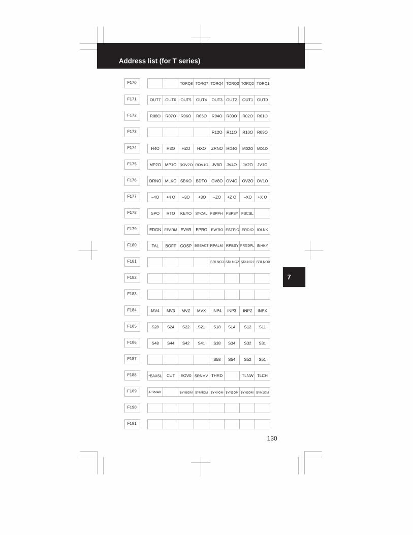
3
1
4
5
6
7
8
9
10
2
Address list (for T series)
130
F170 TORQ8 TORQ7 TORQ4 TORQ3 TORQ2 TORQ1
F171 OUT7 OUT6 OUT5 OUT4 OUT3 OUT2 OUT1 OUT0
F172 R08O R07O R06O R05O R04O R03O R02O R01O
F173 R12O R11O R10O R09O
F174 H4O H3O HZO HXO ZRNO MD4O MD2O MD1O
F175 MP2O MP1O ROV2O ROV1O JV8O JV4O JV2O JV1O
F176 DRNO MLKO SBKO BDTO OV8O OV4O OV2O OV1O
F177 –4O +4 O –3O +3O –ZO +Z O –XO +X O
F178 SPO RTO KEYO SYCAL FSPPH FSPSY FSCSL
F179 EDGN EPARM EVAR EPRG EWTIO ESTPIO ERDIO IOLNK
F180 TAL BOFF COSP BGEACT RPALM RPBSY PRGDPL INHKY
F181 SRLNO3 SRLNO2 SRLNO1 SRLNO0
F182
F183
F184 MV4 MV3 MVZ MVX INP4 INP3 INPZ INPX
F185 S28 S24 S22 S21 S18 S14 S12 S11
F186 S48 S44 S42 S41 S38 S34 S32 S31
F187 S58 S54 S52 S51
F188 *EAXSL CUT EOV0 SRNMV THRD TLNW TLCH
F189 RSMAX SYN6OM SYN5OM SYN4OM SYN3OM SYN2OM SYN1OM
F190
F191

7. STATUS DISPLAY BY SELF DIAGNOSTIC DISPLAY
131
F192
F193 M228 M224 M222 M221 M218 M214 M212 M211
F194 M318 M314 M312 M311 M238 M234 M232 M231
F195 M338 M334 M332 M331 M328 M324 M322 M321
F196 UO107 UO106 UO105 UO104 UO103 UO102 UO101 UO100
F197 UO115 UO114 UO113 UO112 UO111 UO110 UO109 UO108
F198 UO123 UO122 UO121 UO120 UO119 UO118 UO117 UO116
F199 UO131 UO130 UO129 UO128 UO127 UO126 UO125 UO124
PMC→CMC
PMC window DI
#7 #6 #5 #4 #3 #2 #1 #0
G200
to
PMC window DIG209
G210 EBUFA ECLRA ESTPA ESOFA ESBKA EFINA
G211 EC7A EC6A EC5A EC4A EC3A EC2A EC1A EC0A
G212 EIF7A EIF6A EIF5A EIF4A EIF3A EIF2A EIF1A EIF0A
G213 EIF15A EIF14A EIF13A EIF12A EIF11A EIF10A EIF9A EIF8A
G214 EID7A EID6A EID5A EID4A EID3A EID2A EID1A EID0A
G215 EID15A EID14A EID13A EID12A EID11A EID10A EID9A EID8A
G216 EID23A EID22A EID21A EID20A EID19A EID18A EID17A EID16A
G217 EID31A EID30A EID29A EID28A EID27A EID26A EID25A EID24A
G218 EBUFB ECLRB ESTPB ESOFB ESBKB EFINB
G219 EC7B EC6B EC5B EC4B EC3B EC2B EC1B EC0B
G220 EIF7B EIF6B EIF5B EIF4B EIF3B EIF2B EIF1B EIF0B

3
1
4
5
6
7
8
9
10
2
Address list (for T series)
132
G221 EIF15B EIF14B EIF13B EIF12B EIF11B EIF10B EIF9B EIF8B
G222 EID7B EID6B EID5B EID4B EID3B EID2B EID1B EID0B
G223 EID15B EID14B EID13B EID12B EID11B EID10B EID9B EID8B
G224 EID23B EID22B EID21B EID20B EID19B EID18B EID17B EID16B
G225 EID31B EID30B EID29B EID28B EID27B EID26B EID25B EID24B
G226
G227
G228
G229 MRDYA ORCMA SFRA SRVA CTH1A CTH2A TLMHA TLMLA
G230 RCHA RSLA SOCNA MCFNA SPSLA *ESPA ARSTA
G231
G232
G233 MRDYB ORCMB SFRB ERVB CTH1B CTH2B TLMHB TLMLB
G234 PCHB RSLB SOCNB MCFNB SPSLB *ESPB ARSTB
G235
G236
G237 SYN6M SYN5M SYN4M SYN3M SYN2M SYN1M
G238 PK6M PK5M PK4M PK3M PK2M PK1M
G239 RMTDI7 RMTDI6 RMTDI5 RMTDI4 RMTDI3 RMTDI2 RMTDI1 RMTDI0
Operator’s panel DIG240
to
Operator’s panel DIG249

7. STATUS DISPLAY BY SELF DIAGNOSTIC DISPLAY
133
CMC→PMC
PMC window DO
#7 #6 #5 #4 #3 #2 #1 #0
F250
to
PMC window DOF269
F270 EBSYA EOTNA EOTPA EGENA EDENA EIALA ECKZA EINPA
F271 EMFA
F272 EM28A EM24A EM22A EM21A EM18A EM14A EM12A EM11A
F273 EBSYB EOTNB EOTPB EGENB EDENB EIALB ECZKB EINPB
F274 EMFB
F275 EM28B EM24B EM22B EM21B EM18B EM14B EM12B EM11B
F276 B7 B6 B5 B4 B3 B2 B1 B0
F277 B15 B14 B13 B12 B11 B10 B9 B8
F278 B23 B22 B21 B20 B19 B18 B17 B16
F279 B31 B30 B29 B28 B27 B26 B25 B24
F280 SBSY SZP SALR SGEN PCFNA PCHPA CFINA CHPA
F281 ORARA TLMA LDT2A LDT1A SARA SDTA SSTA ALMA
F282 PCFNA PCHPA CFINA CHPA
F283
F284
F285 ORARB TLMB LDT2B LDT1B SARB SDTB SSTB ALMB
F286 PCFNB PCHPB CFINB CHPB
F287
F288

3
1
4
5
6
7
8
9
10
2
Address list (for T series)
134
F289 RMTDO7 RMTDO6 RMTDO5 RMTDO4 RMTDO3 RMTDO2 RMTDO1 RMTDO0
Operator’s panel DOF290
to
Operator’s panel DOF299

7. STATUS DISPLAY BY SELF DIAGNOSTIC DISPLAY
135
Address list (for 0–TTC)
� Interface between CNC and PMC or machine tool
Diagnostic number and PMC address of 0–TTC machine interface signal
DiagnosticNo.
PMC address
Direction of signal Selection of toolpost
000to
040
X000to
X040Machine tool � CNC
Tool post 1 and toolpost 2
048to
086
Y048to
Y086PMC � Machine tool
Tool post 1 and toolpost 2
100to
147
G100to
G147PMC � CNC Tool post 1
148to
199
F148to
F199CNC � PMC Tool post 1
200to
249
G200to
G249PMC � CNC Tool post 1
250to
299
F250to
F299CNC � PMC Tool post 1
100to
147
G1300to
G1347PMC � CNC Tool post 2
148to
187
F1348to
F1387CNC � PMC Tool post 2
200to
209
G1400to
G1409PMC � CNC Tool post 2
250to
279
F1450to
F1479CNC � PMC Tool post 2
Machine interface signal (MT → CNC) (for tool post 1, 2)
#7 #6 #5 #4 #3 #2 #1 #0
000X000
M18–36 M18–21 M18–5 M18–35 M18–20 M18–34 M18–19 M18–33
002X002
M18–24 M18–8 M18–38 M18–23 M18–7 M18–37 M18–22 M18–6
004X004
M18–11 M18–41 M18–26 M18–10 M18–40 M18–25 M18–9 M18–39
006X006
M18–45 M18–14 M18–44 M18–13 M18–43 M18–12 M18–42 M18–27
008 SKIPM –MIT2M +MIT2MX008
M18–49 M18–18 M18–48 M18–17 M18–47 M18–16 M18–46 M18–15
–MIT1M +MIT1M ZAEM XAEM

3
1
4
5
6
7
8
9
10
2
Address list (for 0–TTC)
136
010 / / / /X010
M20–11 M20–41 M20–26 M20–10
012X012
M20–45 M20–14 M20–44 M20–13 M20–43 M20–12 M20–42 M20–27
014X014
M20–49 M20–18 M20–48 M20–17 M20–47 M20–16 M20–46 M20–15
016 *DEC3 / *DECXM / *DECXSX016
M1–6 M1–38 M1–20 M1–21 M1–11 M1–12
017 *DEC4 / *DECZM / *DECZSX017
M1–7 M1–39 M1–22 M1–23 M1–9 M1–10
*ESPS018 / *+LZM / TRT2 / /X018
M1–8 M1–40 M1–24 M1–25
019 / / / /X019
M20–40 M20–25 M20–9 M20–39
020X020
M1–13 M1–37 M1–5 M1–14 M1–15 M1–16 M1–17 M1–18
*ESPM021X021
M1–41 M1–26 M1–27 M1–19 M1–33 M1–34 M1–35 M1–36
022X022
M1–42 M1–43 M1–44 M1–45 M1–46 M1–47 M1–48 M1–49
040 SKIPS *+LZS –MIT2S+MIT2S –MIT1S +MIT1S ZAES XAESX040
M28–11 M28–17 M28–10 M28–16 M28–9 M28–15 M28–8 M28–14
NOTE An alphabet at the tail of a signal name indicates as follows :
�� . . �M ; Signal for tool post 1
�� . . �S ; Signal for tool post 2
When the signals are discriminated per page between tool post 1
and tool post 2, the alphabet at the tail is omitted.
Machine interface signal (PMC → MT) (for tool post 1, 2)
#7 #6 #5 #4 #3 #2 #1 #0
048 /Y048
M2–5 M2–6 M2–7 M2–8 M2–27 M2–26 M2–25
049 / / /Y049
M2–9 M2–41 M2–22 M2–23 M2–24

7. STATUS DISPLAY BY SELF DIAGNOSTIC DISPLAY
137
050 / / / /Y050
M2–10 M2–20 M2–19 M2–21
051Y051
M2–33 M2–34 M2–35 M2–36 M2–37 M2–38 M2–39 M2–40
052Y052
M2–11 M2–12 M2–13 M2–14 M2–15 M2–16 M2–17 M2–18
053Y053
M2–42 M2–43 M2–44 M2–45 M2–46 M2–47 M2–48 M2–49
080Y080
M19–8 M19–7 M19–6 M19–5 M19–4 M19–3 M19–2 M19–1
082Y082
M19–16 M19–15 M19–14 M19–13 M19–12 M19–11 M19–10 M19–9
084Y084
M20–36 M20–21 M20–5 M20–35 M20–20 M20–34 M20–19 M20–33
086Y086
M20–24 M20–8 M20–38 M20–23 M20–7 M20–37 M20–22 M20–6
Machine interface signal (PMC → CNC) (for tool post 1)
#7 #6 #5 #4 #3 #2 #1 #0
100 ED7 ED6 ED5 ED4 ED3 ED2 ED1 ED0G100
101 ED15 ED14 ED13 ED12 ED11 ED10 ED9 ED8G101
102 ESTB EA6 EA5 EA4 EA3 EA2 EA1 EA0G102
103 AFL PRC SPC SPB SPA SPD SRNG103
104 RRW *FLWUG104
105 SVF4 SVF3 SVFZ SVFXG105
106 K7, 0 K6, F K5, Z K4, X K3, R K2, W K1, U K0, SG106
107 KEOB KH, I, K KA, C KP, Q KT,. KM,– K9, G K8, NG107
108 KSTART KINOUT KDELET KINSRT KALTERG108
109 KALARM KDGNOS KPARAM KOFSET KPRGRM KPOSG109

3
1
4
5
6
7
8
9
10
2
Address list (for 0–TTC)
138
110 KCAN KXZ KPAGE↑ KPAGE↓ KCUS↑ KCUS↓G110
111 KRESETG111
112 KSL KS1 KS2 KS3 KS4 KS5 KSRG112
113 KFWH KFUV KFZJ KFXY KFRC KFGB KFN) KFO(G113
114 KFL+ *KFT KFS= KFM# KFF KFE KFK@ KFI,G114
115 BFIN TFIN SFIN MFING115
116 HX/ROV1 ROV3D ROV2D ROV1D –X +X SBK BDTG116
117 HZ/ROV2 –Z + Z MLK MP1/MINPG117
118 DRN GR2 GR1 MP2G118
H3 –3 + 3 MP2
�Lower stage is selected when parameter No. 0031#5 is 1.
119 H4 –4 + 4 *LDSPG119
120 ZRN *SSTP SOR SAR FIN ST STLK MIXG120
121 ERS RT *SP *ESP *OV8 *OV4 *OV2 *OV1G121
122 PN8 PN4 PN2 PN1 KEY MD4 MD2 MD1G122
123 STSP *SCPF *SUCPF COFFG123
DRN SPSTP *SCPF *SUCPF GR2 GR1 COFF
�Lower stage is selected when parameter No. 0031#5 is 1.
124 R081 R071 R061 R051 R041 R031 R021 R011G124
125 SIND SSIN SGN R12I R11I R10I R09IG125
126 CDZ SMZ *OV16 OVC HI4 HI3 HIZ HIXG126
127 DNCI *ABSM MIZ IGNVRYG127
128 IT4 IT3 ITZ ITXG128
129G129
130 UI7 UI6 UI5 UI4 UI3 UI2 UI1 UI0G130

7. STATUS DISPLAY BY SELF DIAGNOSTIC DISPLAY
139
131 UI15 UI14 UI13 UI12 UI11 UI10 UI9 UI8G131
132 GOQSM GOQSM OFN5 OFN4 OFN3 OFN2 OFN1 OFN0G132
TRT2PC133 WOSET SLSPB SLSPA NOWTG133
134 MFIN3 MFIN2 EXWT EXSTP EXRD ENBKYG134
135G135
�For custom macro
136G136
�For custom macro
137G137
�For custom macro
138 –*EDCZ *–EDCX *+EDCZ *+EDCXG138
139G139
140 VINTG140
141 BDT9 BDT8 BDT7 BDT6 BDT5 BDT4 BDT3 BDT2G141
142G142
143G143
144 EAX4 EAX3 EAX2 EAX1G144
145G145
146G146
147G147
Machine interface signal (CNC → PMC) (for tool post 1)
#7 #6 #5 #4 #3 #2 #1 #0
148 OP SA STL SPL ZP4 ZP3 ZPZ ZPXF148
149 MA TAP ENB DEN BAL RST ALF149
150 BF DST TF SF MFF150
151 M28 M24 M22 M21 M18 M14 M12 M11F151
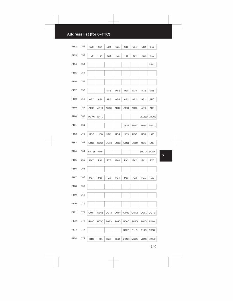
3
1
4
5
6
7
8
9
10
2
Address list (for 0–TTC)
140
152 S28 S24 S22 S21 S18 S14 S12 S11F152
153 T28 T24 T22 T21 T18 T14 T12 T11F153
154 SPALF154
155F155
156F156
157 MF3 MF2 M38 M34 M32 M31F157
158 AR7 AR6 AR5 AR4 AR3 AR2 AR1 AR0F158
159 AR15 AR14 AR13 AR12 AR11 AR10 AR9 AR8F159
160 PSYN WATO ESEND ERENDF160
161 ZP24 ZP23 ZP2Z ZP2XF161
162 UO7 UO6 UO5 UO4 UO3 UO2 UO1 UO0F162
163 UO15 UO14 UO13 UO12 UO11 UO10 UO9 UO8F163
164 PRTSF RWD SUCLP SCLPF164
165 PX7 PX6 PX5 PX4 PX3 PX2 PX1 PX0F165
166F166
167 PZ7 PZ6 PZ5 PZ4 PZ3 PZ2 PZ1 PZ0F167
168F168
169F169
170F170
171 OUT7 OUT6 OUT5 OUT4 OUT3 OUT2 OUT1 OUT0F171
172 R08O R07O R06O R05O R04O R03O R02O R01OF172
173 R12O R11O R10O R09OF173
174 H4O H3O HZO HXO ZRNO MD4O MD2O MD1OF174

7. STATUS DISPLAY BY SELF DIAGNOSTIC DISPLAY
141
175 MP2O MP1O ROV2O ROV1O JV8O JV4O JV2O JV1OF175
176 DRNO MLKO SBKO BDTO OV8O OV4O OV2O OV1OF176
177 –4O +4O –3O +3O –ZO +ZO –XO +X OF177
178 SPO RTO KEYOF178
179F179
180 TAL BOFF COSP BGEACT RPALM RPBSY PRGDPL INHKYF180
181F181
182F182
�For custom macro
183F183
184F184
185F185
186F186
187F187
188F188
189F189
190F190
191F191
192F192
193 M228 M224 M222 M221 M218 M214 M212 M211F193
194 M318 M314 M312 M311 M238 M234 M232 M231F194
195 M338 M334 M332 M331 M328 M324 M322 M321F195
196 UO107 UO106 UO105 UO104 UO103 UO102 UO101 UO100F196

3
1
4
5
6
7
8
9
10
2
Address list (for 0–TTC)
142
197 UO115 UO114 UO113 UO112 UO111 UO110 UO109 UO108F197
198 UO123 UO122 UO121 UO120 UO119 UO118 UO117 UO116F198
199 UO131 UO130 UO129 UO128 UO127 UO126 UO125 UO124F199
Machine interface signal (PMC → CNC) (for tool post 1)
#7 #6 #5 #4 #3 #2 #1 #0
200G200 PMC window DI
201G201 PMC window DI
202G202 PMC window DI
[Kind of data]
203G203 PMC window DI
[No. of words of data]
204G204 PMC window DI
[Axis number]
205G205 PMC window DI
[0 0]
206G206 PMC window DI
207G207 PMC window DI
208G208 PMC window DI
209G209 PMC window DI
210 EBUFA ECLRA ESTPA ESOFA ESBKA EFINAG210
211 EC7A EC6A EC5A EC4A EC3A EC2A EC1A EC0AG211
212 EIF7A EIF6A EIF5A EIF4A EIF3A EIF2A EIF1A EIF0AG212
213 EIF15A EIF14A EIF13A EIF12A EIF11A EIF10A EIF9A EIF8AG213
214 EID7A EID6A EID5A EID4A EID3A EID2A EID1A EID0AG214
215 EID15A EID14A EID13A EID12A EID11A EID10A EID9A EID8AG215
216 EID23A EID22A EID21A EID20A EID19A EID18A EID17A EID16AG216

7. STATUS DISPLAY BY SELF DIAGNOSTIC DISPLAY
143
217 EID31A EID30A EID29A EID28A EID27A EID26A EID25A EID24AG217
218 EBUFB ECLRB ESTPB ESOFB ESBKB EFINBG218
219 EC7B EC6B EC5B EC4B EC3B EC2B EC1B EC0BG219
220 EIF7B EIF6B EIF5B EIF4B EIF3B EIF2B EIF1B EIF0BG220
221 EID15B EID14B EID13B EID12B EID11B EID10B EID9B EID8BG221
222 EID7B EID6B EID5B EID4B EID3B EID2B EID1B EID0BG222
223 EID15B EID14B EID13B EID12B EID11B EID10B EID9B EID8BG223
224 EID23B EID22B EID21B EID20B EID19B EID18B EID17B EID16BG224
225 EID31B EID30B EID29B EID28B EID27B EID26B EID25B EID24BG225
226G226
227G227
228G228
229G229
230G230
231G231
232G232
233G233
234G234
235G235
236G236
237G237
238G238
239G239

3
1
4
5
6
7
8
9
10
2
Address list (for 0–TTC)
144
240G240 Operator’s panel DI
241G241 Operator’s panel DI
242G242 Operator’s panel DI
243G243 Operator’s panel DI
244G244 Operator’s panel DI
245G245 Operator’s panel DI
246G246 Operator’s panel DI
247G247 Operator’s panel DI
248G248 Operator’s panel DI
249G249 Operator’s panel DI
Machine interface signal (CNC → PMC) (for tool post 1)
250F250 PMC window DO
251F251 PMC window DO
252F252 PMC window DO
[Transferred data]
253F253 PMC window DO
[Transferred data]
254F254 PMC window DO
[Transferred data]
255F255 PMC window DO
[Transferred data]
256F256 PMC window DO
[Transferred data]
257F257 PMC window DO
[Transferred data]
258F258 PMC window DO
[Transferred data]

7. STATUS DISPLAY BY SELF DIAGNOSTIC DISPLAY
145
259F259 PMC window DO
[Transferred data]
260F260 PMC window DO
[Transferred data]
261F261 PMC window DO
[Transferred data]
262F262 PMC window DO
[Transferred data]
263F263 PMC window DO
[Transferred data]
264F264 PMC window DO
[Transferred data]
265F265 PMC window DO
[Transferred data]
266F266 PMC window DO
[Transferred data]
267F267 PMC window DO
[Transferred data]
268F268 PMC window DO
269F269 PMC window DO
270 EBSYA EGENA EDENA EIALA ECXZA EINPAF270
271 EMFAF271
272 EM28A EM24A EM22A EM21A EM18A EM14A EM12A EM11AF272
273 EBSYB EGEND EDENB EIALB ECKZB EINPBF273
274 EMFBF274
275 EM28B EM24B EM22B EM21B EM18B EM14B EM12B EM11BF275
276 B7 B6 B5 B4 B3 B2 B1 B0F276
277 B15 B14 B13 B12 B11 B10 B9 B8F277

3
1
4
5
6
7
8
9
10
2
Address list (for 0–TTC)
146
278 B23 B22 B21 B20 B19 B18 B17 B16F278
279 B31 B30 B29 B28 B27 B26 B25 B24F279
280F280
281F281
282F282
283F283
284F284
285F285
286F286
287F287
288F288
289F289
290F290 Operator’s panel DO
291F291 Operator’s panel DO
292F292 Operator’s panel DO
293F293 Operator’s panel DO
294F294 Operator’s panel DO
295F295 Operator’s panel DO
296F296 Operator’s panel DO
297F297 Operator’s panel DO
298F298 Operator’s panel DO
299F299 Operator’s panel DO

7. STATUS DISPLAY BY SELF DIAGNOSTIC DISPLAY
147
Machine interface signal (PMC → CNC) (for tool post 2)
#7 #6 #5 #4 #3 #2 #1 #0
100 ED7 ED6 ED5 ED4 ED3 ED2 ED1 ED0G1300
101 ED15 ED14 ED13 ED12 ED11 ED10 ED9 ED8G1301
102 ESTB EA6 EA5 EA4 EA3 EA2 EA1 EA0G1302
103 AFL PRC SPC SPB SPA SPD SPNG1303
104 RRW *FLWUG1304
105 SVFZ SVFXG1305
106 K7, 0 K6, F K5, Z K4, X K3, R K2, W K1, U K0, SG1306
107 KEOB KH, I, K KA, C KP, Q KT,. KM,– K9, G K8, NG1307
108 KSTART KINOUT KDELET KINSRT KALTERG1308
109 KALARM KDGNOS KPARAM KOFSET KPRGRM KPOSG1309
110 KCAN KXZ KPAGE↑ KPAGE↓ KCUS↑ KCUS↓G1310
111 KRESETG1311
112 KSL KS1 KS2 KS3 KS4 KS5 KSRG1312
113 KFWH KFUV KFZJ KFXY KFRC KFGB KFN) KFO(G1313
114 KFL+ KFT* KFS= KFM# KFF KFE KFK@ KFI,G1314
115 BFIN TFIN SFIN MFING1315
116 HX/ROV1 ROV3D ROV2D ROV1D –X +X SBK BDTG1316
117 HZ/ROV2 –Z + Z MLK MP1/MINPG1317
118 DRN GR2 GR1 MP2G1318
119G1319
120 ZRN *SSTP SOR SAR FIN ST STLK MIXG1320
121 ERS RT *SP *ESP *OV8 *OV4 *OV2 *OV1G1321
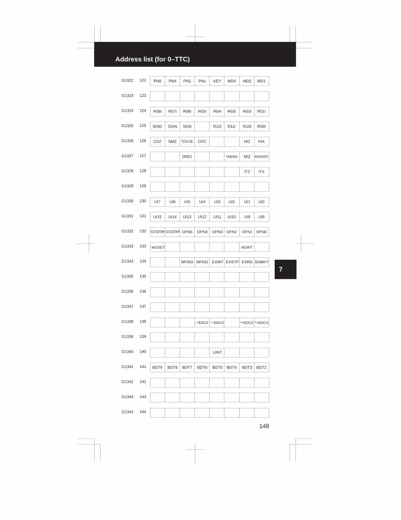
3
1
4
5
6
7
8
9
10
2
Address list (for 0–TTC)
148
122 PN8 PN4 PN2 PN1 KEY MD4 MD2 MD1G1322
123G1323
124 R08I R07I R06I R05I R04I R03I R02I R01IG1324
125 SIND SSIN SGN R12I R11I R10I R09IG1325
126 CDZ SMZ *OV16 OVC HIZ HIXG1326
127 DNCI *ABSM MIZ IGNVRYG1327
128 ITZ ITXG1328
129G1329
130 UI7 UI6 UI5 UI4 UI3 UI2 UI1 UI0G1330
131 UI15 UI14 UI13 UI12 UI11 UI10 UI9 UI8G1331
132 GOQSM GOQSM OFN5 OFN4 OFN3 OFN2 OFN1 OFN0G1332
133 WOSET NOWTG1333
134 MFIN3 MFIN2 EXWT EXSTP EXRD ENBKYG1334
135G1335
136G1336
137G1337
138 –*EDCZ *–EDCX *+EDCZ *+EDCXG1338
139G1339
140 UINTG1340
141 BDT9 BDT8 BDT7 BDT6 BDT5 BDT4 BDT3 BDT2G1341
142G1342
143G1343
144G1344

7. STATUS DISPLAY BY SELF DIAGNOSTIC DISPLAY
149
145G1345
146G1346
147G1347
Machine interface signal (CNC → PMC) (for tool post 2)
#7 #6 #5 #4 #3 #2 #1 #0
148 OP SA STL SPL ZPZ ZPXF1348
149 MA TAP ENB DEN RST ALF1349
150 BF DST TF SF MFF1350
151 M28 M24 M22 M21 M18 M14 M12 M11F1351
152 S28 S24 S22 S21 S18 S14 S12 S11F1352
153 T28 T24 T22 T21 T18 T14 T12 T11F1353
154 SPALF1354
155F1355
156F1356
157 MF3 MF2 M38 M34 M32 M31F1357
158 AR7 AR6 AR5 AR4 AR3 AR2 AR1 AR0F1358
159 AR15 AR14 AR13 AR12 AR11 AR10 AR9 AR8F1359
160 WATO ESEND ERENDF1360
161 ZP2Z ZP2XF1361
162 UO7 UO6 UO5 UO4 UO3 UO2 UO1 UO0F1362
163 UO15 UO14 UO13 UO12 UO11 UO10 UO9 UO8F1363
164 PRTSF RWDF1364
165 PX7 PX6 PX5 PX4 PX3 PX2 PX1 PX0F1365
166F1366

3
1
4
5
6
7
8
9
10
2
Address list (for 0–TTC)
150
167 PZ7 PZ6 PZ5 PZ4 PZ3 PZ2 PZ1 PZ0F1367
168F1368
169F1369
170F1370
171 OUT7 OUT6 OUT5 OUT4 OUT3 OUT2 OUT1 OUT0F1371
172 R08O R07O R06O R05O R04O R03O R02O R01OF1372
173 R12O R11O R10O R09OF1373
174 HZO HXO ZRNO MD4O MD2O MD1OF1374
175 MP2O MP1O ROV2O ROV1O JV8O JV4O JV2O JV1OF1375
176 DRNO MLKO SBKO BDTO OV8O OV4O OV2O OV1OF1376
177 –ZO +Z O –XO +X OF1377
178 SPO RTO KEYOF1378
179F1379
180 BGEACT RPALM RPBSY RPGDPL INHKYF1380
181F1381
182F1382
183F1383
184F1384
185F1385
186F1386
187F1387
188F1388
189F1389

7. STATUS DISPLAY BY SELF DIAGNOSTIC DISPLAY
151
190F1390
191F1391
192F1392
193 M228 M224 M222 M221 M218 M214 M212 M211F1393
194 M318 M314 M312 M311 M238 M234 M232 M231F1394
195 M338 M334 M332 M331 M328 M324 M322 M321F1395
196 UO107 UO106 UO105 UO104 UO103 UO102 UO101 UO100F1396
197 UO115 UO114 UO113 UO112 UO111 UO110 UO109 UO108F1397
198 UO123 UO122 UO121 UO120 UO119 UO118 UO117 UO116F1398
199 UO131 UO130 UO129 UO128 UO127 UO126 UO125 UO124F1399
Machine interface signal (PMC → CNC) (for tool post 2)
PMC window DI
#7 #6 #5 #4 #3 #2 #1 #0
200G1400
201G1401 PMC window DI
202G1402 PMC window DI
[Kind of data]
203G1403 PMC window DI
[No. of words of data]
204G1404 PMC window DI
[Axis number]
205G1405 PMC window DI
[0 0]
206G1406 PMC window DI
207G1407 PMC window DI
208G1408 PMC window DI
209G1409 PMC window DI

3
1
4
5
6
7
8
9
10
2
Address list (for 0–TTC)
152
Machine interface signal (CNC → PMC) (for tool post 2)
#7 #6 #5 #4 #3 #2 #1 #0
250F1450 PMC window DO
251F1451 PMC window DO
252F1452 PMC window DO
[Transferred data]
253F1453 PMC window DO
[Transferred data]
254F1454 PMC window DO
[Transferred data]
255F1455 PMC window DO
[Transferred data]
256F1456 PMC window DO
[Transferred data]
257F1457 PMC window DO
[Transferred data]
258F1458 PMC window DO
[Transferred data]
259F1459 PMC window DO
[Transferred data]
260F1460 PMC window DO
[Transferred data]
261F1461 PMC window DO
[Transferred data]
262F1462 PMC window DO
[Transferred data]
263F1463 PMC window DO
[Transferred data]
264F1464 PMC window DO
[Transferred data]
265F1465 PMC window DO
[Transferred data]

7. STATUS DISPLAY BY SELF DIAGNOSTIC DISPLAY
153
266F1466 PMC window DO
[Transferred data]
267F1467 PMC window DO
[Transferred data]
268F1468 PMC window DO
269F1469 PMC window DO
270F1470
271F1471
272F1472
273F1473
274F1474
275F1475
276 B7 B6 B5 B4 B3 B2 B1 B0F1476
277 B15 B14 B13 B12 B11 B10 B9 B8F1477
278 B23 B22 B21 B20 B19 B18 B17 B16F1478
279 B31 B30 B29 B28 B27 B26 B25 B24F1479

3
1
4
5
6
7
8
9
10
2
Address list (for CNC without PMC)
154
Address list (for CNC without PMC)
(1) M series
(a) MT → CNC (without PMC)
#7 #6 #5 #4 #3 #2 #1 #0
000X000
M18–36 M18–21 M18–5 M18–35 M18–20 M18–34 M18–19 M18–33
002X002
M18–24 M18–8 M18–38 M18–23 M18–7 M18–37 M18–22 M18–6
004 4NGX004
M18–11 M18–41 M18–26 M18–10 M18–40 M18–25 M18–9 M18–39
006X006
M18–45 M18–14 M18–44 M18–13 M18–43 M18–12 M18–42 M18–27
008 SKIP *RILKX008
M18–49 M18–18 M18–48 M18–17 M18–47 M18–16 M18–46 M18–15
ZAE XAEYAE
010 / / / /X010
M20–11 M20–41 M20–26 M20–10
012X012
M20–45 M20–14 M20–44 M20–13 M20–43 M20–12 M20–42 M20–27
014X014
M20–49 M20–18 M20–48 M20–17 M20–47 M20–16 M20–46 M20–15
016 HX/ROV1 / *DECX / –X +X SBK BDTX016
M1–6 M1–38 M1–20 M1–21 M1–11 M1–12
017 / *DECY / –Y +Y MLK *ILKX017
M1–7 M1–39 M1–22 M1–23 M1–9 M1–10
HY/ROV2
HZ/DRN018 / *DECZ / –Z + Z / /X018
M1–8 M1–40 M1–24 M1–25
019 H4 / *DEC4 / –4 + 4 / /X019
M20–40 M20–25 M20–9 M20–39
020 ZRN *SSTP SOR SAR FIN ST MP2 MP1/MINPX020
M1–13 M1–37 M1–5 M1–14 M1–15 M1–16 M1–17 M1–18
021 ERS RT *SP *ESP *OV8 *OV4 *OV2 *OV1X021
M1–41 M1–26 M1–27 M1–19 M1–33 M1–34 M1–35 M1–36
022 PN8 PN4 PN2 PN1 KEY MD4 MD2 MD1X022
M1–42 M1–43 M1–44 M1–45 M1–46 M1–47 M1–48 M1–49

7. STATUS DISPLAY BY SELF DIAGNOSTIC DISPLAY
155
(b) CNC → MT (without PMC)
#7 #6 #5 #4 #3 #2 #1 #0
048 OP SA STL SPL / ZPZ/EF ZPY ZPXY048
M2–5 M2–6 M2–7 M2–8 M2–27 M2–26 M2–25
049 MA / / ENB DEN / RST ALY049
M2–9 M2–41 M2–22 M2–23 M2–24
050 / / DST / TF SF / MFY050
M2–10 M2–20 M2–19 M2–21
051 M28 M24 M22 M21 M18 M14 M12 M11Y051
M2–33 M2–34 M2–35 M2–36 M2–37 M2–38 M2–39 M2–40
052 S28 S24 S22 S21 S18 S14/GR30Y052
M2–11 M2–12 M2–13 M2–14 M2–15 M2–16 M2–17 M2–18
S12/GR20 S11/GR10
053 T28 T24 T22 T21 T18 T14 T12 T11Y053
M2–42 M2–43 M2–44 M2–45 M2–46 M2–47 M2–48 M2–49
080Y080
M19–8 M19–7 M19–6 M19–5 M19–4 M19–3 M19–2 M19–1
082Y082
M19–16 M19–15 M19–14 M19–13 M19–12 M19–11 M19–10 M19–9
084 ZP4Y084
M20–36 M20–21 M20–5 M20–35 M20–20 M20–34 M20–19 M20–33
086Y086
M20–24 M20–8 M20–38 M20–23 M20–7 M20–37 M20–22 M20–6
(2) T series
(a) MT → CNC (without PMC)
#7 #6 #5 #4 #3 #2 #1 #0
000X000
M18–36 M18–21 M18–5 M18–35 M18–20 M18–34 M18–19 M18–33
002X002
M18–24 M18–8 M18–38 M18–23 M18–7 M18–37 M18–22 M18–6
004X004
M18–11 M18–41 M18–26 M18–10 M18–40 M18–25 M18–9 M18–39
006X006
M18–45 M18–14 M18–44 M18–13 M18–43 M18–12 M18–42 M18–27

3
1
4
5
6
7
8
9
10
2
Address list (for CNC without PMC)
156
SKIP3SKIP4SKIP
008 SKIPX008 XAEZAE
SKIP2 XAEZAE
M18–49 M18–18 M18–48 M18–17 M18–47 M18–16 M18–46 M18–15
�Lower stage for 0–G
010 / / / /X010
M20–11 M20–41 M20–26 M20–10
012X012
M20–45 M20–14 M20–44 M20–13 M20–43 M20–12 M20–42 M20–27
014X014
M20–49 M20–18 M20–48 M20–17 M20–47 M20–16 M20–46 M20–15
016 HX/ROV1 / *DECX / –X +X SBK BDTX016
M1–6 M1–38 M1–20 M1–21 M1–11 M1–12
017 / *DECY / –Z +Z MLKX017
M1–7 M1–39 M1–22 M1–23 M1–9 M1–10
HY/ROV2 MP1/MINP
DRN018 / *+LZ / GR2 GR1 / /X018
M1–8 M1–40 M1–24 M1–25
019 *DEC3 / *DEC4 / / /X019
M20–40 M20–25 M20–9 M20–39
020 ZRN *SSTP SOR SAR FIN ST STLK MIXX020
M1–13 M1–37 M1–5 M1–14 M1–15 M1–16 M1–17 M1–18
021 ERS RT *SP *ESP *OV8 *OV4 *OV2 *OV1X021
M1–41 M1–26 M1–27 M1–19 M1–33 M1–34 M1–35 M1–36
022 PN8 PN4 PN2 PN1 KEY MD4 MD2 MD1X022
M1–42 M1–43 M1–44 M1–45 M1–46 M1–47 M1–48 M1–49
(b) CNC → MT (without PMC)
#7 #6 #5 #4 #3 #2 #1 #0
048 OP SA STL SPL / ZPT ZPXY048
M2–5 M2–6 M2–7 M2–8 M2–27 M2–26 M2–25
049 MA / / ENB DEN / RST ALY049
M2–9 M2–41 M2–22 M2–23 M2–24
050 / / DST / TF SF / MFY050
M2–10 M2–20 M2–19 M2–21
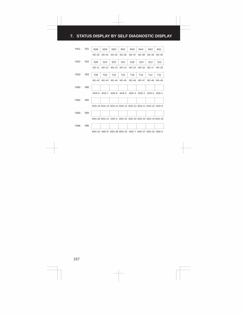
7. STATUS DISPLAY BY SELF DIAGNOSTIC DISPLAY
157
051 M28 M24 M22 M21 M18 M14 M12 M11Y051
M2–33 M2–34 M2–35 M2–36 M2–37 M2–38 M2–39 M2–40
052 S28 S24 S22 S21 S18 S14Y052
M2–11 M2–12 M2–13 M2–14 M2–15 M2–16 M2–17 M2–18
S12 S11
053 T28 T24 T22 T21 T18 T14 T12 T11Y053
M2–42 M2–43 M2–44 M2–45 M2–46 M2–47 M2–48 M2–49
080Y080
M19–8 M19–7 M19–6 M19–5 M19–4 M19–3 M19–2 M19–1
082Y082
M19–16 M19–15 M19–14 M19–13 M19–12 M19–11 M19–10 M19–9
084Y084
M20–36 M20–21 M20–5 M20–35 M20–20 M20–34 M20–19 M20–33
086Y086
M20–24 M20–8 M20–38 M20–23 M20–7 M20–37 M20–22 M20–6

3
1
4
5
6
7
8
9
10
2
158
LEDs on the PC board
LEDMeaning and action to be taken
Number ColorMeaning and action to be taken
L1 Green Blinks during automatic operation. This is not an alarm.
L2 RedLights on any alarm. Take a necessary action accordingto the alarm number displayed on the CRT screen.
L3 Red No memory card is installed.
L4 Red
(1) A watchdog timer alarm occurred. The master PC
board or memory card is defective. � Equiva-
lent to alarm 920
(2) A servo alarm occurred.
(3) An axis card is not installed or is defective.
L5 Red(1) A sub–CPU watchdog timer alarm occurred.
Replace the sub–CPU PC board.
(2) A servo alarm occurred on the fifth or sixth axis.
L6 Red
A system alarm occurred.
(1) The analog interface card is defective.
(2) The DNC1 card is defective.
(3) The seventh– or eighth–axis card is defective.
(1) FS0–C control section A master (A20B–1002–0360)
FS0–Mate master (A20B–1003–0760)
FS0–C control section A (A20B–2000–0170)
L1 �
L2 �
L3 �
L4 �
L5 �
L6 �
�
L1�
L2�
L3�
L4�
L5�
L6
(2) FS0–C control section B master (A20B–1003–0750)(A20B–2000–0180)
� L1� L2� L3� L4� L5� L6

8. HARDWARE
159
8.1 Configuration of CNC Machine Tool
Heatexchanger
Controlunit
Multi–tap transformerfor control unit
I/Ounit
Magnetics circuit
Servo amplifier
Distributionboard
Power supply
Relay connector
Spindleamplifier
(Note 3)
Operator’spanelinterface
Host computer
Machine tool magnetics cabinet

3
1
4
5
6
7
8
9
10
2
160
CRT/MDIunit
Machine operator’s panelManual pulsegenerator
I/Odevice
(Note 1)
Machine tool
(Note 2)
Sensor,Actuator
Servomotor
Spindlemotor
NOTE 1 Refer to FANUC I/O Unit-MODEL A CONNECTION/MAINTE-
NANCE MANUAL (B-61813E)
NOTE 2 Refer to FANUC AC SERVO MOTOR α series DESCRIPTIONS
(B-65142E)
NOTE 3 Refer to FANUC AC SPINDLE MOTOR α series SERIAL INTER-
FACE DESCRIPTIONS (B-65152E)
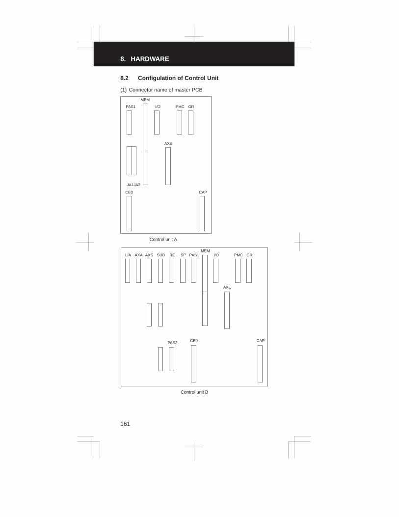
8. HARDWARE
161
8.2 Configulation of Control Unit
(1) Connector name of master PCB
CE0 CAP
AXE
JA1JA2
PAS1 I/O PMC GR
MEM
Control unit A
L/A AXA AXS SUB RE SP
PAS2 CE0
PAS1MEM
I/O
AXE
PMC GR
CAP
Control unit B

3
1
4
5
6
7
8
9
10
2
162
(2) Configulation of PCB
Connectorname
PCB name Specification
Master PCB Control unit A 0–C A20B-2000-0170
0–Mate C A20B-1003-0760A20B-2000-0480
– Control unit B 0–C A20B-2001-0060A20B-2001-0110A20B-2000-0180
00–C A20B-2000-0490
CAP Power unit A A16B-1211-0850
AI A16B-1212-0100
B2 A16B-1212-0110
C A16B-1211-0890
GR Graphic PCB A16B-1211-0920A16B-2200-0350
Manual pulsegenerator in-terface
For two or three manual pulsegenerators
A16B-1210-0801
PMC PMC–M PCB Electrical i t f
ROM A16B-1211-0901interface RAM A16B-1211-0907
Optical i t f
ROM A16B-1211-0903interface RAM A16B-1211-0909
I/O LinkM t l
ROM A16B-2200-0341Master only RAM A16B-2200-0346
I/O Link M t &Sl
ROM A16B-2200-0340Master&Slave RAM A16B-2200-0345
AXE Axis controlPCB (2 to 3/4
0–Mate CFor A/B phase
2 axes A16B-2200-0221PCB (2 to 3/4axes)
For A/B hasepulse coder 3/4 axes A16B-2200-0220
0–CFor A/B phase
2 axes A16B-2200-0361For A/B hasepulse coder 3/4 axes A16B-2200-0360
0–Mate C/0–CResponse for
2 axes A16B-2200-0391
serial pulsecoder
3/4 axes A16B-2200-0390
I/O I/O PCB I/O–C5 (40/40) Sink output type
A16B-1212-0222
I/O–C6 (80/56) Sink output type
A16B-1212-0221
I/O–C7 (104/72) Sink output type
A16B-1212-0220
I/O–E1 (40/40) Source output type
A16B-1211-0972
I/O–E2 (80/56) Source output type
A16B-1211-0971
I/O–E3 (104/72) Source output type
A16B-1211-0970
MEM Memory PCB Respose for serial spindle A16B-1212-0215A16B-1212-0216A16B-2201-0101
For analog spindle A16B-1212-0210A16B-2201-0103
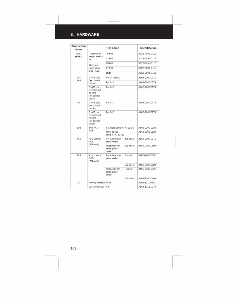
8. HARDWARE
163
Connectorname SpecificationPCB name
PAS1(PAS2)
Cassette formacro execu-
64KB A02B-0091-C111(PAS2) macro execu-
ter 128KB A02B-0091-C113
Main side256KB A02B-0091-C115
Main sidePAS1 (Subside PAS2)
512KB A02B-0098-C117side PAS2)
1MB A02B-0098-C118
JA1JA2
DNC1 card(for control
For 0–Mate C A16B-2200-0771JA2 (for control
unit A) For 0–C A16B-2200-0776
DNC2 cardRemote buff-er card (for controlunit A)
For 0–C A16B-2200-0775
SP DNC1 card(for controlunit B)
For 0–C A16B-2200-0776
DNC2 cardRemote buff-er card (for controlunit B)
For 0–C A16B-2200-0775
SUB Sub PCUPCB
Standard (SUB CPU 16 bit) A16B-2200-0320PCB High–speed
(SUB CPU 32 bit)A16B-2201-0120
AXS Axis controlPCB(5/6 axes)
For A/B phasepulse coder
5/6 axes A16B-2200-0371
(5/6 axes) Response forserial pulsecoder
5/6 axes A16B-2200-0800
AXA Axis controlPCB(7/8 axes)
For A/B phasepulse coder
7 axes A16B-2200-0381
7/8 axes A16B-2200-0380
Response forserial pulsecoder
7 axes A16B-2200-0791
7/8 axes A16B-2200-0790
LA Analog interface PCB A16B-1211-0961
Laser interface PCB A16B-1212-0270

3
1
4
5
6
7
8
9
10
2
164
(3) Connector name
124123
226
P6
A7
A7
19
89
86
4
X4
CPA11
CPA10
M5
M74
M20
CPA9
M228
M29M28
M77
M3
CCX5
M198
M195
M188
M185
M225
M209M206
M73
M12
M26
M1
M224
M204
M18
M184
M227
M208M205
M27
M197
M194
M207
M77 M73
M187
MACRO CASETTE
ANALOG I/F
7/8 AXES
FOR SERIAL
5/6 AXES
FOR SERIAL
SUB CPU
DNC1, DNC2
REMOTE–BUFFER
MEMORY
I/O
3/4 AXES
FOR SERIAL
PMC–M
GRAPHIC
POWERSUPPLYUNIT
CPB1 CPB2

8. HARDWARE
165
Overall machine–to–machine connection diagram (phase A/B
pulse coder capability axis card with no separate detector)
M80
PAS
I/O
MasterPCB
PMC
GR
MEM
Order–made macro cassette
I/O C5–C7PCB
M1
M2C5
M18
M19C6
C7 M20
PMC–M PCB
M24
Graphic/MPGPCB
M21
CCX4
Memory card
CCX5
M3
M5
M74
M12
M26
M27
CPA7 Battery
Relay connector
Operator’spanel
M1A
M2A
M1B
M2B
H20 F
BN3 F
PCBI/O B2
M60
M61
M62
CP51 M78
M79
CN1CRT/MDI
unit
CN2
KM1

3
1
4
5
6
7
8
9
10
2
166
Magneticpanel
FANUC PPRFANUC CASSETTEPortable tape reader
Tape reader
Spindle controlunit
1st 2nd 3rd
MPG MPG MPG
M3 M3 M3
Positioncorder

8. HARDWARE
167
Axis control PCB
AXE
CAP
ON
OFF
Battery (6V)
Power unit
Servo amp1st axis
T1
CN2CN1
Servo amp2nd axis
T1
CN2CN1
Servo amp3rd axis
T1
CN2CN1
Servo amp4th axisCN1
M34
M35
M36
M37
M38
M39
M44
M45
M46
M47
M48
M49
CPA9
CP14
CP15
CP3
CP2
CP2
CP1
T1
CN2
Battery (6V) is necessaryfor the absolute pulsecoder

3
1
4
5
6
7
8
9
10
2
168
AC motor1st axis
AC motor2nd axis
AC motor3rd axis
AC motor4th axis
100VAC Single–phas
AC input3 phase
Electro magneticcontactor
Emergency stop
Fuse
200VACSingle–phase
CH
CH
CH
CH
CH
CH
CH
CH
Servotrans 1
Servotrans 2
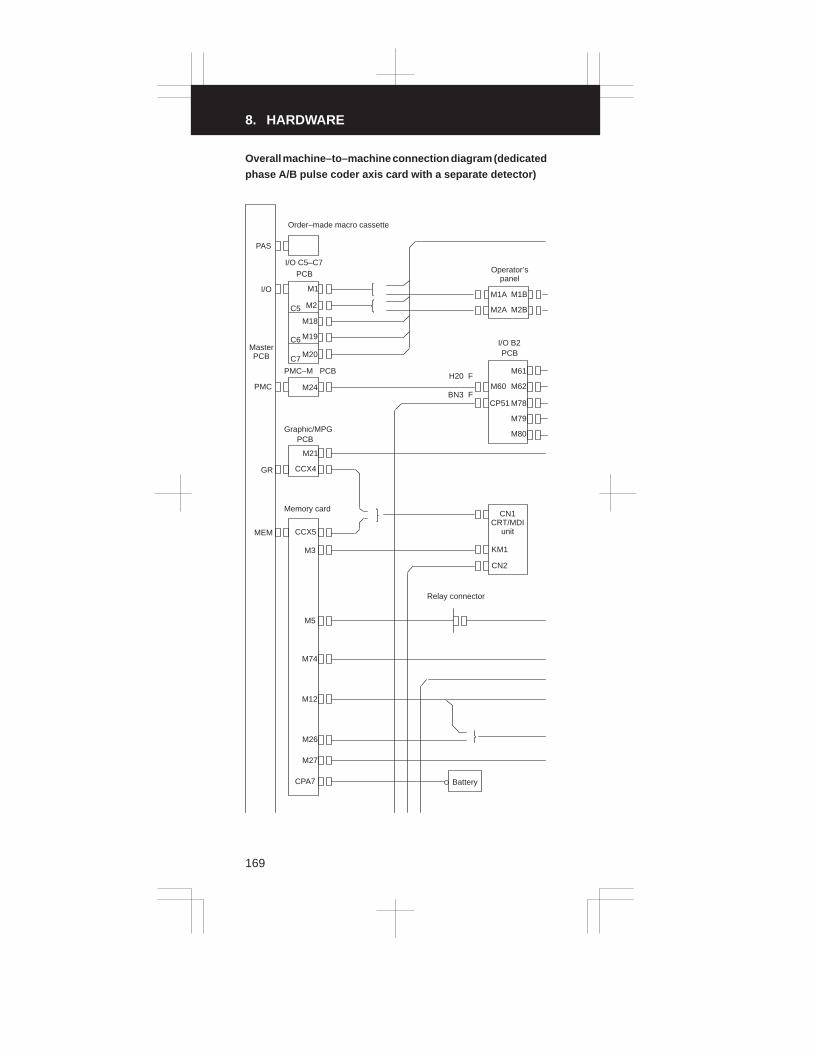
8. HARDWARE
169
Overall machine–to–machine connection diagram (dedicated
phase A/B pulse coder axis card with a separate detector)
M80
PAS
I/O
MasterPCB
PMC
GR
MEM
Order–made macro cassette
I/O C5–C7PCB
M1
M2C5
M18
M19C6
C7 M20
PMC–M PCB
M24
Graphic/MPGPCB
M21
CCX4
Memory card
CCX5
M3
M5
M74
M12
M26
M27
CPA7 Battery
Relay connector
Operator’spanel
M1A
M2A
M1B
M2B
H20 F
BN3 F
PCBI/O B2
M60
M61
M62
CP51 M78
M79
CN1CRT/MDI
unit
CN2
KM1

3
1
4
5
6
7
8
9
10
2
170
Magneticpanel
FANUC PPRFANUC CASSETTEPortable tape reader
Tape reader
Spindle controlunit
1st 2nd 3rd
MPG MPG MPG
M3 M3 M3
Positioncorder

8. HARDWARE
171
Axis control PCB
AXE
CAP
ON
OFF
Battery (6V)
Power unit
Servo amp1st axis
T1
CN2CN1
Servo amp2nd axis
T1
CN2CN1
Servo amp3rd axis
T1
CN2CN1
Servo amp4th axisCN1
M34
M35
M36
M37
M38
M39
M44
M45
M46
M47
M48
M49
CPA9
CP14
CP15
CP3
CP2
CP2
CP1
T1
CN2
Battery (6V) is necessaryfor the absolute pulsecoder

3
1
4
5
6
7
8
9
10
2
172
AC motor1st axis
AC motor2nd axis
AC motor3rd axis
AC motor4th axis
100VAC Single–phas
AC input3 phase
Electro magneticcontactor
Emergency stop
Fuse
200VACSingle–phase
CH
CH
CH
CH
CH
CH
CH
CH
Servotrans 1
Servotrans 2
Speedratetype pulsecoder
Speedratetype pulsecoder
Speedratetype pulsecoder
Speedratetype pulsecoder

8. HARDWARE
173
Overall machine–to–machine connection diagram (serial
pulse coder capability axis card with no separate detector)
M80
PAS
I/O
MasterPCB
PMC
GR
MEM
Order–made macro cassette
I/O C5–C7PCB
M1
M2C5
M18
M19C6
C7 M20
PMC–M PCB
M24
Graphic/MPGPCB
M21
CCX4
Memory card
CCX5
M3
M5
M74
M12
M26
M27
CPA7 Battery
Relay connector
Operator’spanel
M1A
M2A
M1B
M2B
H20 F
BN3 F
PCBI/O B2
M60
M61
M62
CP51 M78
M79
CN1CRT/MDI
unit
CN2
KM1

3
1
4
5
6
7
8
9
10
2
174
Magneticpanel
FANUC PPRFANUC CASSETTEPortable tape reader
Tape reader
Spindle controlunit
1st 2nd 3rd
MPG MPG MPG
M3 M3 M3
Positioncorder

8. HARDWARE
175
Axis control PCB
AXE
CAP
ON
OFF
Battery (6V)
Power unit
Servo amp1st axis
T1
CN2CN1
Servo amp2nd axis
T1
CN2CN1
Servo amp3rd axis
T1
CN2CN1
Servo amp4th axisCN1
M184
CPA9
CP14
CP15
CP3
CP2
CP2
CP1
M185
M186
M187
M188
M189
M194
M195
M196
M197
M198
M199
T1
CN2
Battery (6V) is necessaryfor the absolute pulsecoder

3
1
4
5
6
7
8
9
10
2
176
AC motor1st axis
AC motor2nd axis
AC motor3rd axis
AC motor4th axis
100VACSingle–phas
AC input3 phase
Electro magneticcontactor
Emergency stop
Fuse
200VACSingle–phase
CH
CH
CH
CH
CH
CH
CH
CH
Servotrans 1
Servotrans 2

8. HARDWARE
177
Overall machine–to–machine connection diagram (serial
pulse coder capability axis card with a separate detector)
M80
PAS
I/O
MasterPCB
PMC
GR
MEM
Order–made macro cassette
I/O C5–C7PCB
M1
M2C5
M18
M19C6
C7 M20
PMC–M PCB
M24
Graphic/MPGPCB
M21
CCX4
Memory card
CCX5
M3
M5
M74
M12
M26
M27
CPA7 Battery
Relay connector
Operator’spanel
M1A
M2A
M1B
M2B
H20 F
BN3 F
PCBI/O B2
M60
M61
M62
CP51 M78
M79
CN1CRT/MDI
unit
CN2
KM1

3
1
4
5
6
7
8
9
10
2
178
Magneticpanel
FANUC PPRFANUC CASSETTEPortable tape reader
Tape reader
Spindle controlunit
1st 2nd 3rd
MPG MPG MPG
M3 M3 M3
Positioncorder

8. HARDWARE
179
Axis control PCB
AXE
CAP
ON
OFF
Battery (6V)
Power unit
Servo amp1st axis
T1
CN2CN1
Servo amp2nd axis
T1
CN2CN1
Servo amp3rd axis
T1
CN2CN1
Servo amp4th axisCN1
M184
CPA9
CP14
CP15
CP3
CP2
CP2
CP1
M185
M186
M187
M188
M189
M194
M195
M196
M197
M198
M199
T1
CN2
Battery (6V) is necessaryfor the absolute pulsecoder

3
1
4
5
6
7
8
9
10
2
180
AC motor1st axis
AC motor2nd axis
AC motor3rd axis
AC motor4th axis
100VACSingle–phas
AC input3 phase
Electro magneticcontactor
Emergency stop
Fuse
200VACSingle–phase
CH
CH
CH
CH
CH
CH
CH
CH
Servotrans 1
Servotrans 2
Speedratetype pulsecoder
Speedratetype pulsecoder
Speedratetype pulsecoder
Speedratetype pulsecoder

9. PARAMETERS For M series
181
FUNCTION PARAMETERS (FOR MACHINING CENTER)
(1) Setting parameters
(2) Parameters related to the reader/punch interface and remotebuffer
(3) Parameters related to controlled axes and the increment system
(4) Parameters related to coordinate systems
(5) Parameters related to the stroke limit
(6) Parameters related to the feedrate
(7) Parameters related to acceleration/deceleration control
(8) Parameters related to servo motors
(9) Parameters related to DI/DO
(10) Parameters related to the CRT/MDI, display, and editing
(11) Parameters related to programming
(12) Parameters related to pitch error compensation
(13) Parameters related to spindle control
(14) Parameters related to tool compensation
(15) Parameters related to canned cycles
(16) Parameters related to rigid tapping
(17) Parameters related to scaling and coordinate system rotation
(18) Parameters related to unidirectional positioning
(19) Parameters related to control in the normal direction
(20) Parameters related to index table indexing
(21) Parameters related to custom macro
(22) Parameters related to automatic tool length measurement
(23) Parameters related to graphic display
(24) Parameters related to the display of operation time and number ofparts
(25) Parameters related to tool life management
(26) Parameters related to the position switch function
(27) Parameters related to manual handle feed/manual handle interrupt
(28) Parameters related to the software operator’s panel
(29) Parameters related to program resumption
(30) Parameters related to the high–speed cycle machining/high–speed remote buffer
(31) Parameters related to PMC axis control
(32) Parameters related to surface grinding machines (slanted axiscontrol)
(33) Parameters related to simple synchronous control
(34) Parameters related to the PMC
(35) Parameters related to the function for setting the zero point usingthe butt method
(36) Parameters related to the DNC
(37) Parameters related to the M–NET
NOTE 1 A bit parameter has two meanings, each described on the left and
right of |. The meaning on the left applies when the bit is set to 0
and the meaning on the right applies when it is set to 1.
(Example) The current value is 0/1.
NOTE 2 For details, refer to “Description of Parameters”.

3
1
4
5
6
7
8
9
10
2
182
(1) Setting parameters (1/1)
No. Symbol Description
0000 REVX, Y, 4 The mirror image of each axis is disabled/en-abled.
0000 TVON When a program is registered, a TV check is notexecuted/is executed.
0000 ISO The code system used to output a program isEIA/ISO.
0000 INCH The least input increment (input unit) of a pro-gram is one millimeter/one inch.
0000 I/O Input/output unit on the reader/punch interface
0000 ABS In the MDI mode, commands are specified withincremental values/absolute values.
0000 SEQ Sequence numbers are not automatically in-serted/are automatically inserted.
0000 PWE Parameters cannot be written/can be written.
0000 TAPEF The tape format is not converted/is converted.
0000 PRGNO Number of the program to be stopped when thespecified sequence number is found
0000 SEQNO Number of the sequence to be stopped when it isfound
(2) Parameters related to the reader/punch interface and remote buffer(1/2)
No. Symbol Description
0002#00012#00050#00051#0
STP2STP2STP2STP2
(I/O=0) The stop bit is 1/2.(I/O=1)(I/O=2)(I/O=3)
0002#2
0012#0
ASR33
ASR33
(I/O=0) FANUC PPR etc./20–mA current inter-face
(I/O=1)
0002#3
0012#30050#30051#3
RSASCI
RSASCIRSASCIRSASCI
(I/O=0) The input/output code is ISO or EIA/ASCII.
(I/O=1)(I/O=2)(I/O=3)
0002#7
0012#70050#70051#7
NFED
NFEDNFEDNFED
(I/O=0) Beforehand and afterwards, a feedcharacter is output/is not output.
(I/O=1)(I/O=2)(I/O=3)
0015#5 PRWD The rewind signal is not output/is output to theportable tape reader.
0018#6 TVC In the comment section of a program, a TV checkis executed/is not executed.
0038#1, #20038#4, #50038#6, #7
���, ���
���, ���
���, ���
(I/O=3) Setting the input/output unit(I/O=2)(I/O=0, 1)
0051#1 PARTY (I/O=3) A parity bit is not provided/is provided.
0051#2 SYNAK With protocol B, the output of the SYN and NAKcodes is not controlled/is controlled.
0051#4 NCKCD On the remote buffer interface, the CD (signalquality detection) status is monitored/is not moni-tored.

9. PARAMETERS For M series
183
(2) Parameters related to the reader/punch interface and remote buffer(2/2)
No. Symbol Description
0051#5 ECKL The baud rate clock of the remote buffer is an in-ternal clock/external clock.
0055#0 ASCII Communication of all data except NC data isexecuted in ISO code/ASCII code.
0055#1 ETX The end code is CR/ETX.
0055#2 PROTCA Communication protocol B/A
0055#3 RS42 The remote buffer interface is RS–232–C/RS–422.
0055#7 RMSTS If the remote buffer interface is used with protocolA, the status of the remote buffer in the SAT mes-sage is always returned without specification (=0)/host’s request for switching the SET messageis unconditionally returned.
0070#7 ICR If data is output in ISO code, the EOB code is LF,CR, or CR/LF.
0075#7 IONUL If a null character is detected while EIA codes areread, an alarm does not occur/occurs.
0076#5 PRWD On reader/punch interface 2, rewinding is notexecuted/is executed.
0391#6 RS23BN On the RS–232–C interface, the DC code isused/is not used.
0396#0 NCKER The ER (RS –232C) or TR (RS–422) signal ischecked/is not checked.
0396#2 BCC The BCC value is checked/is not checked.
0396#3 ERCODE A4–digit hexadecimal error code is not appendedto a negative acknowledgement/is appended toa negative acknowledgement.
0399#6 FEDNUL A feed character in a significant information sec-tion is output as a space character/null character.
0250025105520553
– – – – – –– – – – – –– – – – – –– – – – – –
(I/O=2) Baud rate(I/O=3)(I/O=0)(I/O=1)
(3) Parameters related to controlled axes and the increment system (1/2)
No. Symbol Description
0001#07001#0
SCWSCWS
The least command increment (output unit) for alinear axis is one millimeter/inch.
0003#0 to #3
0066#4, #57003#0, #1
ZM� (X to 4) The direction of a reference positionreturn and initial direction are positive/negative.
(7, 8)(5, 6)
0008#2 to #40280
0285, 02867130, 7131
ADW�
– – – – – –– – – – – –– – – – – –
(4) Axis name(4)(7, 8)(5, 6)
0011#20062#4, #57032#0, #1
ADLNADLIN�
ROT�
(4) Rotation axis/linear axis(7, 8) Rotation axis/linear axis(5, 6) Linear axis/rotation axis
0024#1 LII10 The input/output unit is IS–B/IS–A.
0049#4 S3JOG The number of axes that can be simultaneouslycontrolled in manual operation is one/up to three.

3
1
4
5
6
7
8
9
10
2
184
(3) Parameters related to controlled axes and the increment system (2/2)
No. Symbol Description
0057#3 MIC If a decimal point is omitted, the least input incre-ment is not multiplied/is multiplied by ten.
0062#7 C8NG The eighth axis is enabled/disabled.
0066#1 NBD78 If there are more servo axes than controlled axes,the single–axis extension function for the con-trolled axis is disabled/enabled.
0074#0 to #3 CRF� If a reference position return is not made and amovement command other than G28 is speci-fied, an alarm does not occur/occurs.
0076#1 JZRN The function for setting the reference positionwithout dogs is disabled/enabled.
0391#0 to #5 JZRN� The function for setting the reference positionwithout dogs is enabled/disabled.
0398#1 ROAX The roll–over function is disabled/enabled.
0398#2 RODRC The direction of rotation specified in ABS modeis determined so that the distance of rotation isminimized/determined according to the sign ofthe specified value.
0398#3 ROCNT Relative coordinates which are not multiples ofthe travel distance per rotation are not rounded/are rounded.
0399#7 OUTZRN If the remaining travel distance or active miscel-laneous function is found at a manual return tothe reference position, an alarm occurs/does notoccur.
0269 to 0274 – – – – – – Number of a servo axis
0279 – – – – – – Attribute of the fourth axis
7032#7 ROT10S If inch output is specified for the fifth or sixth axis,the unit of parameters related to feedrate is 0.1deg/min/1 deg/min.
(4) Parameters related to coordinate systems (1/2)
No. Symbol Description
0010#77010#7
APRSAPRSS
At a manual reference position return, automaticcoordinate system setting is not executed/isexecuted.
0024#6 CLCL At a manual reference position return, the localcoordinate system is not canceled/is canceled.
0028#5 EX10D When an external workpiece coordinate systemshift is executed, the offset value is the input val-ue/ten–times the input value.
0708 to 0711
0815 to 08180825, 08267708, 7709
– – – – – –
– – – – – –– – – – – –– – – – – –
(X to 4) Coordinates of the reference positionfor automatic coordinate system set-ting
(X to 4)(7, 8)(5, 6)
0735 to 0738
0866, 0867
– – – – – –
– – – – – –
(X to 4) Distance from the first reference posi-tion to the second reference position
(7, 8)
0751 to 0754 – – – – – – Offset from the external workpiece referencepoint on each axis
0755 to 0758 – – – – – – Offset from the first workpiece reference point oneach axis (G54)

9. PARAMETERS For M series
185
(4) Parameters related to coordinate systems (2/2)
No. Symbol Description
0759 to 0762 – – – – – – Offset from the second workpiece referencepoint on each axis (G55)
0763 to 0766 – – – – – – Offset from the third workpiece reference point oneach axis (G56)
0767 to 0770 – – – – – – Offset from the fourth workpiece reference pointon each axis (G57)
0771 to 0774 – – – – – – Offset from the fifth workpiece reference point oneach axis (G58)
0775 to 0778 – – – – – – Offset from the sixth workpiece reference pointon each axis (G59)
0780 to 0783
0868 to 0869
– – – – – –
– – – – – –
(X to 4) Distance from the first reference posi-tion to the third reference position
(7, 8)
0784 to 0787
0870, 0871
– – – – – –
– – – – – –
(X to 4) Distance from the first reference posi-tion to the fourth reference position
(7, 8)
0860 – – – – – – Travel distance per revolution about the rotationaxis
7717 – – – – – – Machine coordinate system when the fifth orsixth axis is a rotation axis
(5) Parameters related to the stroke limit (1/1)
No. Symbol Description
0008#6 OTZN A Z–axis stored stroke check is executed/is notexecuted.
0015#4 LM2 The signal for switching the second stored strokelimit is disabled/enabled.
0024#4 INOUT The inhibited area of the third stored stroke limitis the inside/outside.
0057#5 HOT3 The hardware OT signals +LMX to –LMZ (G129,#0 to #5) are disabled/enabled.
0065#3 PSOT Before a reference position return is made, thestored stroke limit is checked/is not checked.
0076#7 OTRF0M An alarm occurs after the stroke limit is exceed-ed/before the stroke limit is exceeded.
0700 to 0703
0821, 08227700, 7701
– – – – – –
– – – – – –– – – – – –
(X to 4) First stored stroke limit in the positivedirection on each axis
(7, 8)(5, 6)
0704 to 0707
0823, 08247704, 7705
– – – – – –
– – – – – –– – – – – –
(X to 4) First stored stroke limit in the negativedirection on each axis
(7, 8)(5, 6)
0743 to 0746 – – – – – – Second stored stroke limit in the positive direc-tion on each axis
0747 to 0750 – – – – – – Second stored stroke limit in the negative direc-tion on each axis
0804 to 0806 – – – – – – Third stored stroke limit in the positive directionon each axis
0807 to 0809 – – – – – – Third stored stroke limit in the negative directionon each axis

3
1
4
5
6
7
8
9
10
2
186
(6) Parameters related to the feedrate (1/2)
No. Symbol Description
0001#67001#6
RDRNRDRNS
For the rapid traverse command, a dry run is dis-abled/enabled.
0008#5 ROVE The rapid traverse override signal ROV2 (G117,#7) is enabled/disabled.
0010#0 ISOT When a reference position is not established,manual rapid traverse is disabled/enabled.
0011#3 ADNW Feedrate specification A/B
0015#3 SKPF With G31, a dry run, override, or automatic accel-eration/deceleration is disabled/enabled.
0049#6 NPRV When a position coder is not used, the commandof feed per rotation is disabled/enabled.
0049#7 FML10 The unit of parameters in which the rapid traverserate and cutting feedrate are specified is not mul-tiplied/is multiplied by ten.
0059#0 to #2 EDP� Of the commands specifying feed in the positivedirection on each axis, external deceleration isvalid for rapid traverse only/for both rapid tra-verse and cutting feed.
0059#3 to #5 EDM� Of the commands specifying feed in the negativedirection on each axis, external deceleration isvalid for rapid traverse only/for both rapid tra-verse and cutting feed.
0393#1 COVOUT The function for changing the speed of outer arcmachining is disable/enabled.
0393#4 HLCLMP In helical interpolation, the feedrate is notclamped/is clamped to the maximum cutting fee-drate.
0393#5 STOV0 If the cutting feedrate override is 0% in rapid tra-verse, a stop does not occur/occurs.
0397#2 OVR255 The signal of feedrate override in 1% steps is dis-able/enabled.
0213 – – – – – – Minimum deceleration ratio for the speed of innerarc machining by automatic corner override(MDR)
0214 – – – – – – Amount of automatic override for the inside of acorner
0215 – – – – – – Inside angle for determining whether to use auto-matic override for the inside of a corner
0216 – – – – – – Feedrate change corresponding to a graduationon the manual pulse generator when the F com-mand is specified with one digit
0482 – – – – – – Feedrate after acceleration/deceleration for au-tomatic corner deceleration
0483 – – – – – – Difference between feedrates of two blocks, foreach axis, for automatic corner deceleration
0487 – – – – – – Feedrate after acceleration/deceleration for au-tomatic corner deceleration (for look–ahead con-trol)
0495 – – – – – – Maximum feedrate with standard arc radius
0496 – – – – – – Minimum feedrate with standard arc radius
0518 to 05210643, 06447518, 7519
– – – – – –– – – – – –– – – – – –
(X to 4) Rapid traverse feedrate for each axis(7, 8)(5, 6)
0527 – – – – – – Maximum cutting feedrate

9. PARAMETERS For M series
187
(6) Parameters related to the feedrate (2/2)
No. Symbol Description
05307530
– – – – – – (X to 4) FL speed in exponential acceleration/deceleration of cutting feed
(5, 6)
05337533
– – – – – –– – – – – –
(X to 4) F0 speed of rapid traverse override(5, 6)
0534
7534
– – – – – –
– – – – – –
(X to 4) FL speed at a reference position re-turn
(5, 6)
0548 – – – – – – FL speed in exponential acceleration/decelera-tion of manual feed
0549 – – – – – – Cutting feedrate in the automatic mode at power–on
0559 to 0562 – – – – – – Jog rapid traverse rate for each axis
0565, 0566 – – – – – – Jog feedrate when the rotary switch is set to posi-tion 10
0567 – – – – – – Maximum cutting feedrate with feedrate specifi-cation B
0568 – – – – – – F0 speed of rapid traverse override on an addi-tional axis with feedrate specification B
0569 – – – – – – FL speed at a reference position return on anadditional axis with feedrate specification B
0538, 0584 – – – – – – Maximum feedrate by the F command specifiedwith one digit
0580 – – – – – – Start distance (Le) for inner corner automaticoverride
0581 – – – – – – End distance (Ls) for inner corner automaticoverride
0605 to 0608 – – – – – – FL speed of exponential acceleration/decelera-tion for manual feed on each axis
0636 – – – – – – External deceleration speed
0684 – – – – – – Feedrate with which the error detect function as-sumes that deceleration is completed
0788 to 0796 – – – – – – Feedrate corresponding to the F command spe-cified with one digit
0878 – – – – – – FL speed for exponential acceleration/decelera-tion of cutting feed (for look–ahead control)

3
1
4
5
6
7
8
9
10
2
188
(7) Parameters related to acceleration/deceleration control (1/2)
No. Symbol Description
0020#5 NCIPS A position check is executed/is not executed.
0045#3 LSUP For cutting feed, exponential acceleration/decel-eration is executed/linear acceleration/decelera-tion after interpolation is executed.
0045#4 CCINP The in–position width for cutting feed is specifiedwith the same parameters as those used for rapidtraverse (No. 0500 to 0503)/with different param-eters (No. 0609 to 0612)
0048#4 SMZCT Rapid traverse block overlap is disabled/en-abled.
0076#0 ERDT The error detect function is disable/enabled.
0379 – – – – – – Feedrate ratio at which the next block is startedfor block overlap
0393#0 FERDT Automatic corner deceleration is disabled/en-abled.
0395#3 CHEAFD For automatic corner deceleration, control basedon the feedrate difference is disabled /enabled.
0395#6 FWBTYP Linear acceleration/deceleration prior to inter-polation is type A/type B.
0399#2 RPDFF Feed forward control is applied only to cuttingfeed/applied to both cutting feed and rapid tra-verse.
0399#4 CINPS For feed–type–based in–position check (CCINP:bit 4 of parameter 0045), the inposition width forcutting feed is specified using parameters otherthan those for rapid traverse, only when the nextblock also specifies cutting feed/regardless ofthe type of feed specified in the next block.
0480 – – – – – – Parameter 1 for setting the acceleration for linearacceleration/deceleration prior to interpolation
0481 – – – – – – Parameter 2 for setting the acceleration for linearacceleration/deceleration prior to interpolation
0482 – – – – – – Feedrate after acceleration/deceleration for au-tomatic corner deceleration
0483 – – – – – – Difference between feedrates of two blocks, foreach axis, for automatic corner deceleration
0485 – – – – – – Parameter 1 for setting the acceleration for linearacceleration/deceleration prior to interpolation(for look–ahead conrtol)
0486 – – – – – – Parameter 2 for setting the acceleration for linearacceleration/deceleration prior to interpolation(for look–ahead conrtol)
0522 to 0525
0645, 06467522, 7523
– – – – – –
– – – – – –– – – – – –
(X to 4) Time constant of linear acceleration/deceleration in rapid traverse on eachaxis
(7, 8)(5, 6)
0529
7529
– – – – – –
– – – – – –
Time constant of exponential acceleration/decel-eration in cutting feed or manual feed(5, 6)
0601 to 0604 – – – – – – (X to 4) Time constant of exponential accel-eration/deceleration in manual feed oneach axis
0635 – – – – – – Time constant of linear acceleration/decelerationafter interpolation in cutting feed

9. PARAMETERS For M series
189
(7) Parameters related to acceleration/deceleration control (2/2)
No. Symbol Description
0651 to 0656
7651, 7652
– – – – – –
– – – – – –
(X to 8) Time constant of exponential accel-eration/deceleration in cutting feed ona PMC axis
(5, 6)
0863 – – – – – – Standard arc radius for feedrate clamp accordingto arc radius
0864 – – – – – – Critical angle between two blocks for automaticcorner deceleration (for advanced preview con-trol)
0865 – – – – – – Critical angle between two blocks for automaticcorner deceleration
0877 – – – – – – Time constant for exponential acceleration/ de-celeration of cutting feed (for advanced previewcontrol)
0879 – – – – – – Time constant for linear acceleration /decelera-tion after interpolation of cutting feed (for ad-vanced preview control)
0952 to 0955 – – – – – – (X to 4th) Time constant T2 for rapid traversebell–shaped acceleration/deceleration for eachaxis
(8) Parameters related to servo motors (1/2)
No. Symbol Description
0004 to 0007
0067, 00680570 to 0575
7004, 70057570, 7571
GRD�
GRD�
– – – – – –DMR�
– – – – – –
(X to 4) Capacity of the reference counter ofeach axis
(7, 8)(X to 8)(5, 6)(5, 6)
0004 to 0007
0067, 00687004, 7005
DMR�
DMR�
DMR�
(X to 4) Detection multiplication of each axis(DMR)
(7, 8)(5, 6)
0010#27010#2
OFFVYOFFVYS
If VRDY is set to 1 before PRDY is set to 1, analarm occurs/does not occur.
0021#0 to #5
7021#0, #1
APC�
APC�
(X to 8) For each axis, an absolute–positiondetector is not used/is used.
(5, 6)
0021#6 NOFLUP At power–on before the reference position is es-tablished by the absolute–position detector, a fol-low–up is executed/is not executed.
0022#0 to #5
7022#0, #1
ABS�
ABS�
(X to 8) The reference position has not yetbeen established/has already beenestablished by the absolute–positiondetector.
(5, 6)
0035#77035#7
ACMRACMRS
(X to 8) An optional CMR is not used/is used.
(5, 6)
0037#0 to #57037#0, #1
SPTP�
SPTP�
(X to 8) As a position detector, a separatepulse coder is not used/is used.
(5, 6)
0037#77037#7
PLCO1PLCO1S
(X to 8) A high–resolution pulse coder is notused/is used.
(5, 6)
0076#4 ADBLS Cutting feed and rapid traverse separate back-lash is disabled/enabled.

3
1
4
5
6
7
8
9
10
2
190
(8) Parameters related to servo motors (2/2)
No. Symbol Description
0390#0 to #5 NREQ� If an absolute pulse coder is used for each axisand the zero point is not established before pow-er–on, an alarm requesting a return to the refer-ence position does not occur/occurs.
0399#3 SFDEC The reference position shift function is disabled/enabled.
0399#5 FUNO If a servo alarm is detected by the CNC, a follow–up is executed/is not executed.
0100 to 0103
0275, 02767100, 7101
– – – – – –
– – – – – –– – – – – –
(X to 4) Command multiplication of each axis(CMR)
(7, 8)(5, 6)
0265 – – – – – – Time interval for leveling the current value dis-play on the servo adjustment screen
0452 to 0457
0739 to 07420827, 08287580, 75817739, 7740
– – – – – –
– – – – – –– – – – – –– – – – – –– – – – – –
(X to 8 3RD WORD) Count at the zero point of the APC
(X to 4 LOWER 2 WORD)(7, 8 LOWER 2 WORD)(5, 6 3RD WORD)(5, 6 LOWER 2 WORD)
0500 to 05030637, 06387500, 7501
– – – – – –– – – – – –– – – – – –
(X to 4) Effective area on each axis(7, 8)(5, 6)
0504, 7507
0639, 06407504, 7505
– – – – – –
– – – – – –– – – – – –
(X to 4) Limit on position error for each axisduring traveling
(7, 8)(5, 6)
0508 to 05110641, 06427508, 7509
– – – – – –– – – – – –– – – – – –
(X to 4) Grid shift amount for each axis(7, 8)(5, 6)
0512 to 0515
0632, 0633
– – – – – –
– – – – – –
(X to 4) Loop gain of position control for eachaxis
(7, 8)
0517
7517
– – – – – –
– – – – – –
(X to 4) Loop gain of position control commonto all axes
(5, 6)
0535 to 05380647, 06487535, 7536
– – – – – –– – – – – –– – – – – –
(X to 4) Backlash compensation for each axis(7, 8)(5, 6)
0593 to 0596
0649, 06507593, 7594
– – – – – –
– – – – – –– – – – – –
(X to 4) Limit on position error for each axisduring a stop
(7, 8)(5, 6)
0609 to 0612 – – – – – – (X to 4th) In–position width for cutting feed foreach axis
0956 – – – – – – Distance between the position at which the de-celeration dog is turned off and the first grid point

9. PARAMETERS For M series
191
(9) Parameters related to DI/DO (1/1)
No. Symbol Description
0001#2 DCS The START key on the MDI panel is connectedthrough the machine/is not connected throughthe machine.
0001#5
7001#5
DECI
DECIS
(X to 4) At a reference position return, decel-eration occurs when the decelerationsignal is set to 0/1.
(5, 6)
0003#4
7003#4
OVRI
OVRIS
(X to 4) Acceleration occurs when the overridesignal or rapid traverse override signalis set to 0/1.
(5, 6)
0008#7 EILK Interlock occurs on all axes or Z–axis only/on anindividual axis.
0009#0 to #3
7009#0 to #3
TFIN
TFIN
(X to 4) Time period in which the signal (FIN,bit 3 of G120) indicating that the mis-cellaneous function, spindle–speedfunction, or tool function has beencompleted is accepted
(5, 6)
0009#4 to #7
7009#4 to #7
TMF
TMF
(X to 4) Period up to the time when the signalindicating that the code of the miscel-laneous function, spindle–speed func-tion, or tool function is read is sent
(5, 6)
0012#1 ZILK Interlock occurs on all axes/Z–axis only.
0015#2 RIKL The high–speed interlock signal *RILK (X008,#5) is disabled/enabled.
0019#1 C4NG The signal to ignore the fourth axis 4NG (X004,#7) is disabled/enabled.
0020#4 BCD3 For the B code, six digits/three digits are output.
0045#2 RWDOUT The rewind signal RWD (F164, #6) is output onlywhen the tape reader is rewinding/is output whilea program in memory is rewound.
0045#7 HSIF For processing the M, S, T, and B codes, the stan-dard interface is used/the high–speed interfaceis used.
0049#0 DILK The signal for separate interlock in the directionof each axis is disabled/enabled.
0049#1 RDIK The high–speed interlock signal is always en-abled/is disabled when the signal for separate in-terlock in the direction of each axis is set to 1.
0070#4 DSTBGE When output is started in background editing, thesignal for starting manual data input DST (F150,#5) is output/is not output.
0252 – – – – – – Extension time for the reset signal

3
1
4
5
6
7
8
9
10
2
192
(10) Parameters related to the CRT/MDI, display, and editing (1/3)
No. Symbol Description
0001#1 PROD In the relative coordinate display, tool lengthcompensation is included/is not included.
0001#4 IOF An offset value is input from the MID panel in theABS mode/INC mode.
0002#17002#1
PPDPPDS
Coordinate system setting does not cause rela-tive coordinates to be pre–set/causes relativecoordinates to be pre–set.
0010#1 EBCL When a program in memory is displayed, theEOB code is displayed as ;/�.
0011#7 MCINP By MINP (G120, #0), a program is not registered/is registered in memory.
0013#4 INHMN Menus are displayed/are not displayed.
0015#0 CBLNK The cursor blinks/does not blink.
0015#1 NWCH The amount of tool wear compensation is dis-played with a character W/without a character W.
0015#6 REP If a program registered from the reader/punch in-terface has the same number as another pro-gram registered in memory, an alarm occurs/theprogram is replaced.
0018#5 PROAD In the absolute coordinate display, tool lengthcompensation is included/is not included.
0018#7 EDITB With the standard keyboard, editing A isexecuted/editing B is executed.
0019#6 NEOP M02, M30, or M99 terminates program registra-tion/does not terminate program registration.
0019#7 DBCD On the diagnostic screen, the data of a timercounter is displayed in binary/decimal.
0023#0 to #6 ���� Setting of the language to be used on the display
0028#0 PRCPOS On the program check screen, relative coordi-nates are displayed/absolute coordinates aredisplayed.
0028#2 DACTF The actual speed is not displayed/is displayed.
0028#3 MMDL In MDI operation B, the modal status is not dis-played/is displayed.
0029#6 DSPSUB On the absolute or relative position displayscreen, the fifth or sixth axis is not displayed/isdisplayed.
0035#0 to #3 NDSP� The current position on each axis is displayed/isnot displayed.
0038#3 FLKY With the CRT or MDI, a standard keypad is used/full keypad is used.
0040#0 NAMPR On the program directory screen, programnames are not displayed/are displayed.
0040#4 SORT On the program directory screen, programs arearranged in the order in which they are regis-tered/in the ascending order of program num-bers.
0045#0 RDL Under I/O unit external control, reading dependson the REP bit (bit 6 of parameter 0015)/a pro-gram is registered after all programs are deleted.
0045#1 RAL Reading on the reader/punch interface causesall programs to be registered/only the first pro-gram to be registered.

9. PARAMETERS For M series
193
(10) Parameters related to the CRT/MDI, display, and editing (2/3)
No. Symbol Description
0048#7 SFFDSP The soft–key display and control depend on theconfiguration of additional functions/areexecuted regardless of additional functions.
0050#1 NOFMK When a sequence number is searched for, theformat is checked/is not checked.
0056#0 NOCND When the length of part program storage is 120or 320 m, or if the background editing function isprovided, memory is automatically compressed/is not automatically compressed.
0057#0 PWNNC At power–on, the MMC screen is displayed/CNCscreen is displayed.
0057#1 ALMNC If an alarm occurs in the CNC while the MMCscreen is displayed, the MMC screen is dis-played/CNC screen is displayed.
0057#2 SALNC If a system alarm occurs in the CNC while theMMC screen is displayed, the MMC screen isdisplayed/CNC screen is displayed.
0060#0 DADRDP On the diagnostic screen, addresses are not dis-played/are displayed.
0060#2 LDDSPG Dynamic ladder display is not executed/isexecuted.
0060#3 C14DGN When a 14–inch CRT is used, the diagnosticscreen of the 9–inch format is displayed/14–inchformat is displayed.
0060#5 OPMNDP Operating monitor display is invalid/valid.
0060#6 EXTSP The function to search for or display a protectedprogram is disabled/enabled.
0060#7 IGNCOL On a 9–inch high–resolution CRT, monochromescreens are displayed/color screens are dis-played.
0061#6 DSP78 In absolute and relative coordinates on the cur-rent position display, the coordinate on theseventh or eighth axis is not included/is included.
0063#0 MTDSPI Machine coordinates are not displayed accord-ing to the input system/are displayed accordingto the input system.
0063#1 PRSTIN Automatic coordinate system setting in the inchinput mode is specified in parameter 0708 andsubsequent parameters/in parameter 0815 andsubsequent parameters.
0064#0 SETREL Pre–setting relative coordinates causes clearingto zero/optional values to be used.
0064#1 ALLPRE For pre–setting relative coordinates, the stan-dard specification is selected/axes are selectedby numeric keys.
0064#3 IOMDGN On the diagnostic screen, DI/DO of the I/O Linkand an extended R/D area are not displayed/aredisplayed.
0064#5 NPA If an alarm occurs or an operator message is in-put, the alarm or message screen is displayedinstead/is not displayed.
0066#0 ALL56 On the complete current position screen, the fifthor six axis is not displayed/is displayed.
0076#2 IOP Input or output of an NC program can be stoppedby an NC reset/only by pressing the [STOP] softkey.

3
1
4
5
6
7
8
9
10
2
194
(10) Parameters related to the CRT/MDI, display, and editing (3/3)
No. Symbol Description
0077#2 SGD Servo waveform display is invalid/valid.
0077#6 HLKEY The MDI keys are not processed in the high–speed mode/are processed in the high–speedmode.
0078#0 NOINOW The amount of tool wear compensation can be in-put with the MDI keys/cannot be input with theMDI keys.
0078#1 NOINOG The amount of tool geometry compensation canbe input with the MDI keys/cannot be input withthe MDI keys.
0078#2 NOINMV A macro variable can be input with the MDI keys/cannot be input with the MDI keys.
0078#3 NOINWZ An offset from the workpiece reference point canbe input with the MDI keys/cannot be input withthe MDI keys.
0389#0 SRVSET The servo setting screen is displayed/is not dis-played.
0393#2 WKNMDI If the automatic operation is started or halted, anoffset from the workpiece reference point can beinput with the MDI keys/cannot be input with theMDI keys.
0393#7 DGNWEB If PWE is set to 0, a PMC parameter cannot beinput/can be input.
0395#1 TLSCUR On the offset screen, the cursor position is not re-tained/is retained.
0397#7 SERNAI The contents of alarm 409 are not displayed/aredisplayed.
0398#0 WKINC With the MDI keys, an offset from the workpiecereference point is input in the ABS mode/INCmode.
0337 to 0346 – – – – – – Character codes of the title
0351 to 0355 – – – – – – Character codes of the NC name
0550 – – – – – – Increment used when the sequence number isautomatically inserted
0797 – – – – – – Encryption
0798 – – – – – – Key
(11) Parameters related to programming (1/2)
No. Symbol Description
0010#4 PRG9 Editing of subprograms from O9000 to O9999 isnot inhibited/is inhibited.
0011#6 G01 The mode selected at power–on is G00/G01.
0015#7 CPRD If a decimal point is omitted, the selected unit isthe least input increment/mm, inch, deg, and sec.
0016#3 NPRD Decimal point input or display is used/is notused.
0019#5 M02NR After M02 is executed, a return to the beginningof the program is made/is not made.
0028#4 EXTS External program number search is invalid/valid.
0029#5 MABS In MDI operation B, the ABS or INC command de-pends on setting ABS/G90 or G91.
0030#7 G91 The mode selected at power–on is G90/G91.

9. PARAMETERS For M series
195
(11) Parameters related to programming (2/2)
No. Symbol Description
0045#6 CLER Pressing the RESET key, setting the external re-set signal or an emergency stop sets the systemin the reset state/clear state.
0057#7 MBCLR When a reset occurs, MDI–B programs are notcleared/are cleared.
0063#2 M198P Address P of M198 is used with a file number/pro-gram number.
0065#7 M3B A single block can contain only one M code/up tothree M codes.
0389#2 PRG8 Editing of programs from O8000 to 8999 is not in-hibited/is inhibited.
0391#7 NOCLR In the clear state, a specific G code is cleared/isnot cleared.
0393#3 M3PQNG An M code specified with three digits is valid/in-valid.
0393#6 RADCHK When circular interpolation is specified, the dif-ference between the radius values at the startpoint and end point is not checked/is checked.
0394#6 WKZRST In workpiece coordinate system setting, an NCreset does not cause a return to G54/causes a re-turn to G54.
0394#7 CAKEY On the parameter, diagnostic, or offset screen,pressing the CAN key does not erase a singlecharacter/erases a single character.
0395#0 DLG99 In the feed per rotation mode, the dwell commandis specified with a time period/spindle speed.
0396#7 EORRE If EOR is read without the program end com-mand, an alarm occurs/a reset occurs.
0111, 0112 – – – – – – M code which is not buffered
0212 – – – – – – Plane selected at power–on
0484 – – – – – – Program number for parameter, macro variable,or diagnostic data
0634 – – – – – – Program number registered in a simultaneous in-put/output operation
0876 – – – – – – Limit of arc radius error
(12) Parameters related to pitch error compensation (1/1)
No. Symbol Description
0011#0, #1
7011#0, #1
PML�
PML�S
(X to 4) Magnification of pitch error compensa-tion
(5, 6)
0712 to 0715
7713, 7714
– – – – – –
– – – – – –
(X to 4) Interval of pitch error compensation foreach axis
(5, 6)
1000 to 6000 – – – – – – Reference position of pitch error compensationfor each axis
1001 to 6128 – – – – – – Pitch error compensation for each axis

3
1
4
5
6
7
8
9
10
2
196
(13) Parameters related to spindle control (1/2)
No. Symbol Description
0003#5 GST By SOR (G120, #5), spindle orientation isexecuted/a gear–change is executed.
0012#6 G84S If the G74 or G84 cycle is specified, the gear ischanged at a point specified through S analogoutput gear–change method A or B/at a pointspecified in parameters 0540 and 0556.
0013#5 ORCW In spindle orientation, S analog output is positive/negative.
0013#6, #7 TCW, CWM Sign output in S analog output
0014#0 SCTA The spindle speed arrival signal is checkedconditionally/always.
0020#7 SFOUT SF (F150, #2) is output when a gear–change ismade/even if a gear–change is not made.
0024#2 SCTO The spindle speed arrival signal SAR (G120, #4)is not checked/is checked.
0028#6, #7 PSG� Gear ratio between the spindle and position cod-er
0029#4 FSOB Under constant surface speed control, SF (F150,#2) is output/is not output.
0035#6 LGCM The gear–change speed is the maximum speedof each gear (method A)/is determined by param-eters 0585 and 0586 (method B).
0041#4, #5 SSCA� Axis used as the calculation standard underconstant surface speed control
0062#3 SPMRPM Parameters of spindle speed control are speci-fied in units of 1 RPM/10 RPM.
0065#1 CZRN For the first G00 command after the Cs contourcontrol mode is selected, a reference position re-turn is made, then positioning is executed/nor-mal positioning is executed.
0070#0, #1 DAC� For D/A conversion, the analog interface board isnot used/is used.
0071#0 ISRLPC When the serial interface spindle is used, theposition coder signal is fetched from the opticalfiber cable/connector M27.
0071#4 SRL2SP The number of serial interface spindles con-nected is one/two.
0071#7 FSRSP The serial interface spindle is not used/is used.
0080#2, #3 MORCM� For the first and second spindle motors, thespindle orientation function with the stop positionset externally is not used/is used.
0080#6, #7 SP�NEG The directions of rotation of the first and secondspindles during synchronous control of thespindle are the same as the specified sign/arethe opposite of the specified sign.
0108 – – – – – – Spindle speed in stable spindle rotation
0108 – – – – – – Spindle motor speed at a gear–change
0110 – – – – – – Delay timer if the spindle speed arrival signalSAR (G120, #4) is checked
0303 – – – – – – Permissible difference in the number of errorpulses for phasing in the synchronous controlmode
0516 – – – – – – Data for adjusting the gain under constant sur-face speed control (analog output)

9. PARAMETERS For M series
197
(13) Parameters related to spindle control (2/2)
No. Symbol Description
053905410555
– – – – – –– – – – – –– – – – – –
[Neutral gear] Maximum spindle speed[Low gear][High gear]
0540 to 0543 – – – – – – Spindle speed when the voltage for specifyingthe spindle speed of each gear is 10 V
0540
0556
– – – – – –
– – – – – –
[Neutral gear] Minimum spindle speed in a tap-ping cycle[High gear]
0542 – – – – – – Upper limit of the value output to the spindle mo-tor
0543 – – – – – – Lower limit of the value output to the spindle mo-tor
0551 – – – – – – Minimum spindle speed in the constant surfacespeed control mode (G96)
0556 – – – – – – Maximum spindle speed for the constant surfacespeed control function
0576 – – – – – – Permissible error in the number of error pulsesbetween two spindles in the mode of (simple)synchronous control of the spindle
0577 – – – – – – Spindle speed offset compensation
0585, 0586 – – – – – – Gear–change point in S analog switching meth-od B
0673
0677
– – – – – –
– – – – – –
(Channel 1) Data for adjusting the gain in ana-log output
(Channel 2)
0674
0678
– – – – – –
– – – – – –
(Channel 1) Offset compensation in analogoutput
(Channel 2)
0957 to 0959 – – – – – – Limit of position error during spindle rotation atthe maximum spindle speed
6780 to 6783 – – – – – – Position loop gain of the servo axis in the Cs con-tour control mode
6784 to 6787
6788 to 67916792 to 67956796 to 6799
– – – – – –
– – – – – –– – – – – –– – – – – –
(X) Position loop gain of the servo axis in theCs contour control mode of each gear
(Y)(Z)(4)
7516 – – – – – – Data for adjusting the gain under sub–spindlecontrol by the S command specified with four orfive digits
7539 – – – – – – Sub–spindle speed offset compensation

3
1
4
5
6
7
8
9
10
2
198
(14) Parameters related to tool compensation (1/1)
No. Symbol Description
0001#3 RS43 When a reset occurs, the vector of tool lengthcompensation is cleared/is not cleared.
0003#6 TSLT Tool length compensation is executed on the Z–axis (type A)/an axis vertical to the specifiedplane (type B).
0016#2 SUPM In cutter compensation C, start–up and cancella-tion are executed through the method of typeA/B.
0019#3 TLCD Tool length compensation A or B/C
0030#2 OFCDH Tool compensation memory C is disable/en-abled.
0036#5 TLCDOK In tool length compensation of type C, offset oftwo or more axes is disabled/enabled.
0036#6 OFRD Tool length compensation and cutter compensa-tion are specified with the H code./Tool lengthcompensation and cutter compensation C arespecified with the H code and D code, respective-ly.
0062#2 G40V Operation by a single command (G40, G41, orG42)
0557 – – – – – – Maximum travel distance that can be ignored onthe outside of a corner in cutter compensation C
(15) Parameters related to canned cycles (1/2)
No. Symbol Description
0002#4, #5 PMXY1, 2 Axis and direction on and in which the tool is re-tracted in canned cycle G76 or G87
0011#4 MCF When positioning of G81 terminates, the signal tospecify an external operation function is not out-put/is output.
0012#4 FXCS In canned cycle G74 or G84, reverse and forwardspindle rotations are executed after M05 is out-put/even if M05 is not output.
0012#5 FXCO In canned cycle G76 or G87, an oriented spindlestop is executed after M05 is output/even if M05is not output.
0057#6 FXY The drilling axis in a canned cycle is always theZ–axis/is a programmed axis.
0304 – – – – – – M code for small–diameter peck drilling cycle
0305, 0306 – – – – – – Spindle speed change ratio for small–diameterpeck drilling cycle
0307, 0308 – – – – – – Cutting feedrate change ratio for small–diameterpeck drilling cycle
0309 – – – – – – Minimum cutting feedrate ratio for small–diame-ter peck drilling cycle
0327 – – – – – – Number of macro variable for counting number ofretractions
0328 – – – – – – Number of macro variable for counting number oftimes overload signal has been received
0398#6 CHGSKP Using the overload torque signal, the feedrateand spindle speed are not changed/are changed.
0398#7 CHGNRM Without using the overload torque signal, the fee-drate and spindle speed are not changed/arechanged.

9. PARAMETERS For M series
199
(15) Parameters related to canned cycles (2/2)
No. Symbol Description
0403 – – – – – – Clearance/cutting start point in a peck tappingcycle
0492 – – – – – – Feedrate of retraction to the R position when ad-dress I is omitted
0493 – – – – – – Feedrate of forward movement from the R posi-tion when address I is omitted
0531 – – – – – – Clearance in canned cycle G73 (high–speedpeck drilling cycle)
0532 – – – – – – Cutting start point in canned cycle G83 (peck dril-ling cycle)
0941 – – – – – – Clearance for small–diameter peck drilling cycle
(16) Parameters related to rigid tapping (1/2)
No. Symbol Description
0019#4 SRGTP The rigid tapping selection signal (RGTAP) isG123, #1/G135, #0.
0035#5 RGCTO When the tool is retracted in rigid tapping, thetime constant of acceleration/deceleration on thespindle and tapping axis is the same parameteras that for starting cutting/is a different parameterfrom that for starting cutting.
0037#6 VALT In rigid tapping, the variable time constantswitching function is not used/is used.
0040#2 RGTPE In rigid tapping, the rigid mode is canceled afterthe rigid DI signal is turned off/even before therigid DI signal is turned off.
0063#3 VSLPC An optional gear ratio between the spindle andposition coder is not used/is used.
0063#4 RGDOV When the tool is retracted, an override is dis-abled/enabled.
0065#5 TAPDRN During tapping, a dry run is enabled/disabled.
0076#3 G84RGD G84 and G74 are not handled as G codes for rigidtapping/are handled as G codes for rigid tapping.
0077#1 CT3G Three–stage time constant switching is disabled/enabled.
0388#0 PCTPH A peck tapping cycle is handled as a high–speedpeck tapping cycle.
0388#2 RGMFH A feed hold and single–block operation are en-abled/disabled.
0388#3 RGORT When rigid tapping is started, a spindle referenceposition return is not made/is made.
0388#5 SIG At a gear–change, the SIND signal is disabled/enabled.
0388#6 CHKERC During spindle rotation, the position error ischecked according to the maximum spindlespeed/specified spindle speed.
0254 – – – – – – Type of acceleration/deceleration for the spindleand tapping axis
0255 – – – – – – Spindle backlash amount in rigid tapping
0256 – – – – – – M code for specifying the rigid tapping mode
0258 – – – – – – Override value when the tool is retracted in rigidtapping
0378 – – – – – – Override for rigid tapping return

3
1
4
5
6
7
8
9
10
2
200
(16) Parameters related to rigid tapping (2/2)
No. Symbol Description
0400 to 0402 – – – – – – Time constant of acceleration/deceleration onthe spindle and tapping axis when the tool is re-tracted
0613 – – – – – – Time constant of acceleration/deceleration onthe spindle and tapping axis
0614 – – – – – – FL speed of exponential acceleration/decelera-tion on the spindle and tapping axis
0615 – – – – – – Loop gain of position control on the spindle andtapping axis
0616
06240625
– – – – – –
– – – – – –– – – – – –
(Low gear) Multiplier of loop gain on thespindle
(Neutral gear)(High gear)
0617 – – – – – – Allowable maximum spindle speed in rigid tap-ping
0618 – – – – – – Effective area on the tapping axis in rigid tapping
0619 – – – – – – Effective area on the spindle in rigid tapping
0620 – – – – – – Limit of position error on the tapping axis duringtraveling
0621 – – – – – – Limit of position error on the spindle during travel-ing
0622 – – – – – – Limit of position error on the tapping axis undera stop
0623 – – – – – – Limit of position error on the spindle under a stop
0626 – – – – – – Feedrate for defining the reference lead in rigidtapping
0627 – – – – – – Position error on the spindle in rigid tapping
0628 – – – – – – Spindle pulse distribution in rigid tapping
0663 to 0665 – – – – – – Number of teeth on the spindle when an optionalgear ratio is selected
0666 to 0668 – – – – – – Number of teeth on the position coder when anoptional gear ratio is selected
0669 to 0671 – – – – – – Loop gain of position control
0692
0693
– – – – – –
– – – – – –
(Low gear) Time constant of acceleration/de-celeration on the spindle and tap-ping axis
(Neutral gear)
0694
0695
– – – – – –
– – – – – –
(Low gear) Maximum spindle speed in rigidtapping
(Neutral gear)
0696 – – – – – – Instantaneous difference between errors on thespindle and tapping axis
0697 – – – – – – Maximum difference between errors on thespindle and tapping axis
0799 – – – – – – Integrated spindle pulse distribution in rigid tap-ping
0960 – – – – – – Amount of return � for rigid tapping return

9. PARAMETERS For M series
201
(17) Parameters related to scaling and coordinate system rotation (1/1)
No. Symbol Description
0036#0 to #2 SCL� Scaling for each axis is disabled/enabled.
0036#7 SRC The unit of scaling magnification is0.00001/0.001.
0041#0 RIN An angle of coordinate system rotation is alwaysspecified in the absolute mode/is specified ac-cording to G90 or G91.
0063#6 ESCAL Scaling and programmable mirror image on eachaxis are disabled/enabled.
0730 – – – – – – Angle assumed when the angle of coordinatesystem rotation is not specified
0731 to 0733 – – – – – – Magnification assumed when a scaling magnifi-cation is not specified
(18) Parameters related to unidirectional positioning (1/1)
No. Symbol Description
0029#0 to #3 G60� In unidirectional positioning (G60) for each axis,the direction of approach is positive/negative.
0204 to 0207 – – – – – – Distance of approach in unidirectional position-ing for each axis
(19) Parameters related to control in the normal direction (1/1)
No. Symbol Description
0683 – – – – – – Rotation speed around a controlled axis in thenormal direction
0832 – – – – – – Limit up to which an inserted rotation around acontrolled axis in the normal direction can be ig-nored
0833 – – – – – – Limit on travel distance that can be executed withthe angle in the normal direction of the previousblock
(20) Parameters related to index table indexing (1/1)
No. Symbol Description
0079#0 IXDDP For the axis of index table indexing, the decimalpoint is input using the conventional method/pocket–calculator method.
0079#1 IXREL On the screen, relative coordinates on the index-ing axis which are not multiples of 360� are notrounded/are rounded.
0079#2 IXABS On the screen, absolute coordinates on the in-dexing axis which are not multiples of 360� arenot rounded/are rounded.
0079#3 IXINC When the M code for rotation in the negativedirection is not specified, the direction of rotationin the G90 mode minimizes the distance of rota-tion/does not minimize the distance of rotation.
0079#4 IXG90 An index command depends on specification ofthe G90 or G91 mode/always assumed that theG90 mode.
0079#7 IXTYP Sequence of type A/type B
0249 – – – – – – Code specifying a rotation in the negative direc-tion
0839 – – – – – – Minimum angle in index table indexing

3
1
4
5
6
7
8
9
10
2
202
(21) Parameters related to custom macro (1/1)
No. Symbol Description
0011#5 SBKM By a macro statement, a single–block stop is notmade/is made.
0040#1 DPOSUP If data is output by the DPRINT command, lead-ing zeros are output as space characters/as theyare.
0040#5 TMCR A T code is processed as the code of the toolfunction/code for calling O9000.
0040#6 COMC When a reset occurs, common variables (#100 to#149) are made null/are not made null.
0040#7 LOCC When a reset occurs, local variables (#01 to #33)are made null/are not made null.
0042 ASTCD Hole pattern of the EIA code of an asterisk (*)
0043 EQCD Hole pattern of the EIA code of an equal sign (=)
0044 SHPCD Hole pattern of the EIA code of a sharp (#)
0053 LBLCD Hole pattern of the EIA code of a square bracket([)
0054 RBLCD Hole pattern of the EIA code of a square bracket(])
0056#1 MSKT At an interrupt, absolute coordinates are not setas skip coordinates/are set as skip coordinates.
0056#2 MBLK Custom macro interrupt of type I/type II
0056#3 MSTE The interrupt signal uses the edge trigger meth-od/status trigger method.
0056#4 MPRM The M codes for enabling and disabling an inter-rupt are M96 and M97 respectively/are specifiedin parameters.
0056#5 MSUB When an interrupt occurs, local variables are ofthe macro type/subprogram type.
0056#6 MCYL During a cycle operation, a custom macro inter-rupt is disabled/enabled.
0056#7 MUSR The custom macro interrupt function is disabled/enabled.
0057#4 CROUT After data output in ISO code is completed withB/D PRINT, LF is output/CR/LF is output.
0220 to 0229 – – – – – – G code for calling custom macro from O9010 toO9019
0230 to 0239 – – – – – – M code for calling a custom macro from O9020 toO9029
0240 to 0242 – – – – – – M code for calling a subprogram from O9001 toO9003
0246 – – – – – – M code for enabling a custom macro interrupt
0247 – – – – – – M code for disabling a custom macro interrupt
0248 – – – – – – M code for calling a program registered in a file
(22) Parameters related to automatic tool length measurement (1/1)
No. Symbol Description
0558 – – – – – – Feedrate during automatic tool length measure-ment
0813 – – – – – – Value of � in automatic tool length measurement
0814 – – – – – – Value of � in automatic tool length measurement

9. PARAMETERS For M series
203
(23) Parameters related to graphic display (1/1)
No. Symbol Description
0046#5 GRPOS On the screen of a solid drawing or tool pathdrawing, the current position is not displayed/isdisplayed.
0058#0 SGORG If the coordinate system is changed during draw-ing, drawing is executed on the same coordinatesystem/on the assumption that the current draw-ing point is the current position set in the newcoordinate system.
0058#1 SGTLC During drawing of a solid drawing, tool lengthcompensation is not executed/is executed.
0058#2 SG3PL During drawing of a solid drawing, a triplanedrawing is drawn with the first angle projection/third angle projection.
0058#3 SGPLN During drawing of a solid drawing, a top view isdrawn without ridgelines/with ridgelines.
0058#4 SGFIN During drawing of a solid drawing, a machiningprofile is drawn in the coarse mode/fine mode.
0058#5 SGCSR On a tool path drawing, the current tool positionor the center of a partial magnification is markedwith � / � .
0253 – – – – – – Change in the position of the cross section on atriplane drawing
0589 to 0592 – – – – – – Margin on a solid drawing
0630, 0631 – – – – – – Dot shift of 9–inch high–resolution graphic dis-play
(24) Parameters related to the display of operation time and number of parts(1/1)
No. Symbol Description
0040#3 RWCNT With M02 or M30, the total number of parts to bemachined and the number of parts machined arecounted/are not counted.
0219 – – – – – – M code for counting the total number of parts tobe machined and the number of parts machined
0600 – – – – – – Number of parts required
0779 – – – – – – Total number of parts to be machined

3
1
4
5
6
7
8
9
10
2
204
(25) Parameters related to tool life management (1/1)
No. Symbol Description
0039#0, #1 GST� Number of tool groups that can be registered
0039#2 LCTM The tool life is specified in terms of the number oftimes used/time period.
0039#3 TLSK If the tool skip signal TLSKP (G140, #0) is input,the current group is skipped/the group number isinput together.
0039#4 GRST If the tool skip signal TLSKP (G140, #0) is input,the execution data of the current group is cleared/the execution data of all groups is cleared.
0039#5 IGSK The tool skip signal TLSKP (G140, #0) is ac-cepted always/only while a tool under tool lifemanagement is used.
0039#6 IGIN The tool back numbers are not ignored/are ig-nored.
0039#7 M6TCD A T code in the block containing M06 is assumedas a back number/the command of the group tobe selected next.
0041#7 M6TST If a T code is specified in the block containingM06 under tool life management, the T code isprocessed as a back number or the number of thegroup to be selected next/the counting of the lifeof the tool group is started immediately.
0336 – – – – – – M code for resuming the counting of the tool life
0599 – – – – – – Number with which tool life management is ig-nored
(26) Parameters related to the position switch function (1/1)
No. Symbol Description
0310 to 0319 – – – – – – Axis corresponding to the position switch
0840 to 0849 – – – – – – Maximum value in the operating area of the posi-tion switch
0850 to 0859 – – – – – – Minimum value in the operating area of the posi-tion switch
(27) Parameters related to manual handle feed/manual handle interrupt(1/2)
No. Symbol Description
0002#6 TJHD During teaching in jog mode, the manual pulsegenerator is disabled/enabled.
0003#7 HLSE If the manual pulse generators for three units aremounted, the axis selection signal is disabled/enabled.
0013#0 JHD In the jog mode, the manual pulse generator isdisable/enabled.
0018#0 to #3 N�MP2 For each axis, the magnification of handle feed (x100) is enabled/disabled.
0019#0 MHPGB Multihandle function of specification A/specifica-tion B
0060#4 HDLPM If the handle of the manual pulse generator is ro-tated quickly, the reading and travel distancemay not agree/the travel distance depends onthe reading.

9. PARAMETERS For M series
205
(27) Parameters related to manual handle feed/manual handle interrupt(2/2)
No. Symbol Description
0075#2 INHND The travel increment of manual handle interruptis set as the output unit and acceleration/decel-eration is disabled/input unit and acceleration/deceleration is enabled.
0386#4 to #7 HDPIG� For each axis, the magnification of manual han-dle feed (x 1000) is enabled/disabled.
0117 – – – – – – Manual handle pulse generator of the Z–axis orthe fourth axis
0118 – – – – – – Number of manual pulse generators used
0121 – – – – – – Magnification of manual handle feed (M)
0699 – – – – – – Magnification of manual handle feed (specifica-tion B)
(28) Parameters related to the software operator’s panel (1/1)
No. Symbol Description
0017#0 OPG1 On the software operator’s panel, the mode is notselected/is selected.
0017#1 OPG2 On the software operator’s panel, the selection ofa jog feed axis or rapid traverse is not executed/isexecuted.
0017#2 OPG3 On the software operator’s panel, the selection ofthe manual pulse generator axis switch or magni-fication switch is not executed/is executed.
0017#3 OPG4 On the software operator’s panel, jog feedrateoverride switch is not executed/is executed.
0017#4 OPG5 On the software operator’s panel, BDT, SBK,MLK, or DRN switch is not executed/is executed.
0017#5 OPG6 On the software operator’s panel, protect switchis not executed/is executed.
0017#6 OPG7 On the software operator’s panel, feed holdswitch is not executed/is executed.
0130 to 0137 – – – – – – Axis and direction of jog feed corresponding tokeys on the software operator’s panel
0140 to 0203 – – – – – – Character code of general–purpose switches onthe software operator’s panel
(29) Parameters related to program resumption (1/1)
No. Symbol Description
0387#0 SQDNC During DNC operation, program resumption isdisabled/enabled.
0124 to 0127 – – – – – – Sequence of a jump to the program resumptionpoint
(30) Parameters related to the high–speed cycle machining/high–speedremote buffer (1/1)
No. Symbol Description
0055#4 to #6 ITPCNT Interval compensated for by G05 data
0597 – – – – – – Number of controlled axes of the high–speed re-mote buffer. Maximum number of axes that canbe simultaneously controlled in high–speedcycle machining

3
1
4
5
6
7
8
9
10
2
206
(31) Parameters related to PMC axis control (1/1)
No. Symbol Description
0024#0 IGNPMC PMC axis control is enabled/disabled.
0030#0, #1 EAC� Axis setting for executing PMC axis control(specification A)
0032#47032#4
PNGMLKPNGMLKS
On a PMC axis, a machine lock is enabled/dis-abled.
0032#6 EACSB PMC axis control of specification A/specificationB
0049#5 EFML10 Under PMC axis control, the specified feedrate(cutting feed) is multiplied by one/ten.
0052#0 to #7 NODIC� Under PMC axis control, the current position dis-play depends on the position of the decimal pointwith increment system 1 or 10/depends on thestandard specifications.
0061#0 to #5 EBC� Under PMC axis control (specification B), DI andDO used for each axis are of group A/B.
0062#6 AXPCF To the actual speed display, traveling along aPMC controlled axis is added/is not added.
0063#57063#5
EAXOVEAXOVS
On a PMC axis, a dry run and override are dis-abled/enabled.
0066#3 EPMSKP The skip signal used under PMC axis control isthe same as the corresponding signal of theCNC/is a unique signal.
0066#6, #7 ERVF� Magnification of the speed of feed per rotationunder PMC axis control
0078#4 OVRIE Under PMC axis control, the speed increaseswhen the override signal is set to 0/1.
0078#6 RDRNE Under PMC axis control, a dry run for the rapidtraverse command is disable/enabled.
0078#7 EAXOVE The dry run signal and override signal used underPMC axis control are the same as the corre-sponding signals of the CNC/are unique signals.
0387#7 EFERPD Under PMC axis control, the parameter of therapid traverse rate is the same as that of the CNC/the rapid traverse rate is determined by the fee-drate data specified with the axis control com-mand.
0350 – – – – – – Axis for which the velocity command is executedunder PMC axis control
0462 – – – – – – Time constant of linear acceleration/decelerationfor the velocity specified with the velocity com-mand
0657 to 0662
7657, 7658
– – – – – –
– – – – – –
(X to 4) FL speed of exponential acceleration/deceleration on a PMC axis duringcutting feed
(5, 6)
0672 – – – – – – FL speed on a PMC controlled axis during refer-ence position return
0685 – – – – – – F0 speed of independent rapid traverse overrideon a PMC controlled axis
0698 – – – – – – Maximum speed of feed per rotation about aPMC controlled axis
7021#6 SUB1 PMC controlled axes on the sub–CPU are thefifth and sixth axes/the fifth axis only.

9. PARAMETERS For M series
207
(32) Parameters related to the surface grinding machine (slanted axiscontrol) (1/1)
No. Symbol Description
0077#4 ZRTM1 When a manual reference position return is per-formed on the Y–axis, movement occurs on theZ–axis/does not occur on the Z–axis.
0077#5 AGLST Slanted axis control is not executed/is executed.
0837 – – – – – – Slant angle of the Y–axis
0838 – – – – – – Minimum diameter of the grinding wheel whenthe diameter is checked
(33) Parameters related to simple synchronous control (1/1)
No. Symbol Description
0075#0, #1 SYNM� Master axis under simple synchronous control
0475 – – – – – – Limit of difference between position errors of themaster axis and slave axis
(34) Parameters related to the PMC (1/1)
No. Symbol Description
0028#1 PRCMSG On the program check screen, the remainingtravel distance is displayed/a message from thePMC is displayed.
0060#1 PCLDB The baud rate during ladder loading is 4800bps/9600 bps.
0070#6 PEXRD The R or D area of the PMC–M is not extended/isextended.
0071#6 DPCRAM With the PMC RAM board, PMC LOAD MENU isdisplayed/is not displayed.
0356 to 0359 – – – – – – Number of characters that can be displayed inthe remaining travel distance field on the pro-gram check screen
0476 to 0479 – – – – – – First PMC address at which the characters in theremaining travel distance field are set
(35) Parameters related to the function for setting the zero point using thebutt method (1/1)
No. Symbol Description
0360 to 0363 – – – – – – Torque limit when the cycle for setting the zeropoint using the butt method is in progress
0942, 0943 – – – – – – Butt speed when the cycle for setting the zeropoint using the butt method is executed
0944 to 0947 – – – – – – Traveling speed when the zero point is set in thecycle for setting the zero point using the buttmethod
0948 to 0951 – – – – – – Distance for setting the zero point when the cyclefor setting the zero point using the butt method isexecuted

3
1
4
5
6
7
8
9
10
2
208
(36) Parameters related to the DNC (1/1)
No. Symbol Description
0390#7 NODC3 During DNC operation, reading is executed foreach block/until the buffer is filled.
0320 – – – – – – Time–out period of the no–response timer
0321 – – – – – – Time–out period of the EOT signal timer
0323 – – – – – – Maximum illegal data count
0324 – – – – – – Maximum number of times a message is re–sentby NAK
0325 – – – – – – Maximum number of characters that can be re-ceived after processing to stop transmission iscompleted
0347 – – – – – – Format of connection between the CNC and thehost on the DNC1 interface
0348 – – – – – – Station address of the CNC on the DNC1 inter-face
0490 – – – – – – Maximum length of the datagram (data section)
(37) Parameters related to the M–NET (1/1)
No. Symbol Description
0392#2 SRL1 The character length of the M–NET is 7 bits/8bits.
0392#4 SRPE The vertical parity check of the M–NET is notexecuted/is executed.
0392#5 SREP The vertical parity of the M–NET is an odd parity/even parity.
0392#7 SRS2 The stop bit of the M–NET is bit 1/bit 2.
0259 – – – – – – Byte length of DI of the M–NET
0260 – – – – – – Byte length of DO of the M–NET
0261 – – – – – – Station address of the M–NET
0262 – – – – – – Baud rate of the M–NET
0458 – – – – – – Timer monitor value after the sequence prepar-ing for a connection to the same station is com-pleted
0459 – – – – – – Polling time monitor value in the normal se-quence to the same station
0460 – – – – – – Timer monitor value from the beginning of SAItransmission to the end of BCC transmission
0461 – – – – – – Timer value from the end of reception to the be-ginning of transmission
0463 – – – – – – Destination address of the spindle orientationsignal

9. PARAMETERS For T series
209
List of Parameters for each Function (for Lathe)
(1) Parameters related to setting
(2) Parameters related to the reader/punch interface/remote buffers
(3) Parameters related to controlled axes/increment systems
(4) Parameters related to coordinate systems
(5) Parameters related to stroke limits
(6) Parameters related to the feedrate
(7) Parameters related to acceleration/deceleration control
(8) Parameters related to the servo system
(9) Parameters related to DI/DO
(10) Parameters related to CRT/MDI, display, and editing
(11) Parameters related to programs
(12) Parameters related to pitch error compensation
(13) Parameters related to spindle control
(14) Parameters related to tool compensation
(15) Parameters related to canned cycles
(16) Parameters related to rigid tapping
(17) Parameters related to custom macros
(18) Parameters related to automatic tool compensation
(19) Parameters related to graphic display
(20) Parameters related to run time/parts count display
(21) Parameters related to tool life management
(22) Parameters related to the position switch function
(23) Parameters related to manual handle feed/manual handle interrupt
(24) Parameters related to the software operator’s panel
(25) Parameters related to restarting programs
(26) Parameters related to high–speed cycle machining/high–speedremote buffers
(27) Parameters related to PMC–based axis control
(28) Parameters related to cylindrical grinding machines (GC)
(29) Parameters related to the PMC
(30) Parameters related to the butt–type reference position settingfunction
(31) Parameters related to the DNC
(32) Parameters related to the M–NET
(33) Parameters related to the Cf–axis
(34) Parameters related to 2–path lathes (TT)
(35) Parameters related to polygon turning
(36) Parameters related to synchronized control/axis recomposition
NOTE 1 In the explanation of each bit parameter, the left–hand side of a
slash (/) indicates the state when the bit is set to 0, and the right–
hand side of a slash indicates the state when the bit is set to 1.
Example: The current setting is 0/1.
NOTE 2 For details, see “Parameter Explanation.”

3
1
4
5
6
7
8
9
10
2
210
(1) Parameters related to setting (1/1)
No. Symbol Description
0000 TVON A TV check is not performed/is performed for pro-gram registration.
0000 ISO EIA/ISO is used as the code system for programoutput.
0000 INCH The metric/inch system is used as the least inputincrement (input unit) for programs.
0000 I/O Input/output unit used via the reader/punch inter-face
0000 SEQ Automatic sequence number insertion is not per-formed/is performed.
0000 PWE Parameter write operation is disabled/enabled.
0000 TAPEF Tape format is not converted/is converted.
0000 PRGNO Program number for which sequence number ref-erence is to be stopped
0000 SEQNO Sequence number for which sequence numberreference is to be stopped
(2) Parameters related to the reader/punch interface/remote buffers (1/2)
No. Symbol Description
0002#00012#00050#00051#0
STP2STP2STP2STP2
(I/O=0) The number of stop bits is 1/2.(I/O=1)(I/O=2)(I/O=3)
0002#2
0012#2
ASR33
ASR33
(I/O=0) FANUC PPR, etc./20–mA current in-terface
(I/O=1)
0002#3
0012#30050#30051#3
RSASCI
RSASCIRSASCIRSASCI
(I/O=0) ISO or EIA/ASCII is used as the inputcode.
(I/O=1)(I/O=2)(I/O=3)
0002#7
0012#70050#70051#7
NFED
NFEDNFEDNFED
(I/O=0) Line feed codes are output/not outputbefore and after data output.
(I/O=1)(I/O=2)(I/O=3)
0015#5 PRWD The rewind signal is not output/is output to a por-table tape reader.
0015#6 REP If the same program number is already containedin memory when programs are registered via thereader/punch interface, an alarm is issued/theprogram is replaced.
0018#6 TVC In a program comment, a TV check is not per-formed/is performed.
0038#1, #20038#4, #50038#6, #7
���, ���
���, ���
���, ���
(I/O=3) Input/output unit setting(I/O=2)(I/O=0,1)
0051#1 PARTY (I/O=3) A parity bit is not provided/is provided.
0051#2 SYNAK When protocol B is used, SYN and NAK codeoutput control is not exercised/exercised.
0051#4 NCKCD With the remote buffer interface, the CD (signalquality detection) state is monitored/not moni-tored.
0051#5 ECKL An internal/external clock is used for the remotebuffer baud rate clock.

9. PARAMETERS For T series
211
(2) Parameters related to the reader/punch interface/remote buffers (2/2)
No. Symbol Description
0055#0 ASCII ISO/ASCII code is used for communication of alldata except NC data.
0055#1 ETX The end code is CR/ETX.
0055#2 PROTCA Communication protocol B/A is used.
0055#3 RS42 The remote buffer interface isRS–232–C/RS–422.
0055#7 RMSTS When protocol A is used with the remote bufferinterface, remote buffer state data in an SATmessage is always sent back with no specifica-tion (=0)/a switching request in a SET messagefrom the host is sent back unconditionally.
0070#7 ICR In output using ISO code, the EOB code consistsof an LF, CR, and CR/LF.
0075#7 IONUL When a null character is included in EIA code be-ing read, an alarm is not issued/is issued.
0076#5 PRWD When reader/punch interface 2 is used, rewind isnot performed/is performed.
0391#6 RS23BN When the RS–232–C interface is used, the DCcode is used/not used.
0399#6 FEDNUL For feed operation in a significant informationsection, space/null characters are used.
0250025105520553
– – – – – –– – – – – –– – – – – –– – – – – –
(I/O=2) Baud rate(I/O=3)(I/O=0)(I/O=1)
(3) Parameters related to controlled axes/increment systems (1/2)
No. Symbol Description
0001#07001#0
SCWSCWS
The metric/inch system is used for the least com-mand increment (output unit) for linear axes.
0003#0 to #3
0066#4, #57003#0, #1
ZM� (X to 4) The reference position return direc-tion and initial direction are positive/negative.
(7, 8)(5, 6)
0019#2 XRC For the X–axis, a diameter/radius is specified.
0024#1 LII10 The input/output unit is IS–B/IS–A.
0030#0, #40210, 02110285, 02867130, 7131
ADW�0– – – – – –– – – – – –– – – – – –
(3, 4) Axis name (Display)(3, 4) (Command)(7, 8) (Display)(5, 6) (Display)
0032#2, #3
0062#4, #5
7032#0, #1
LIN�
ADLIN�
ROT�
The third and fourth axes are rotation axes/linearaxes.The seventh and eighth axes are rotation axes/linear axes.(5, 6) Linear axis/rotation axis
0032#77032#7
ROT10ROT10S
The parameter unit for inch output is 0.1 [deg/min]/1 [deg/min].
0049#4 S3JOG The maximum number of simultaneously con-trolled axes in manual operation is 1/3.
0057#3 MIC When the decimal point is omitted, the least inputincrement is not multiplied by 10/multiplied by10.
0062#7 C8NG The eighth axis is enabled/disabled.

3
1
4
5
6
7
8
9
10
2
212
(3) Parameters related to controlled axes/increment systems (2/2)
No. Symbol Description
0066#1 NBD78 When the number of controlled axes is greaterthan the number of servo axes, the extension ofone controlled axis is disabled/enabled.
0069#4 BAX As a command address for the third and fourthaxes, B is not used/used.
0069#5, #6 ���� Incremental or absolute command address forthe third and fourth axes
0074#0 to #3 CRF� If a command other than G28 specifies a move-ment by automatic operation when referenceposition return is not performed, an alarm is notissued/is issued.
0076#1 JZRN The function for setting the reference positionwithout dogs is disabled/enabled.
0385#6 RTLIN Manual reference position return operation for arotation axis is not performed/is performed linear-ly.
0388#1 ROAXC The roll–over function for absolute coordinates isdisabled/enabled.
0388#2 RODRC When the ABS command is specified, the direc-tion of rotation is the direction with the shortestdistance/follows the sign of the specified value.
0388#3 ROCNT The roll–over function for relative coordinates isdisabled/enabled.
0388#5 IGPS90 P/S 090 is enabled/disabled.
0391#0 to #5 JZRN� The function for setting the reference positionwithout dogs is enabled/disabled.
0399#7 OUTZRN If there is distance remaining to travel in manualreference position return, or a miscellaneousfunction is being executed, an alarm (P/S 091) isissued/not issued.
0269 to 0274 – – – – – – Servo axis number
0279, 0280 – – – – – – Attributes of the third and fourth axes
0281, 0282 – – – – – – Axis synchronized with the X–/Z–axis or thethird/fourth axis in synchronized control
0291, 0292 – – – – – – Linear axis/rotation axis to which polar coordi-nate interpolation is applied

9. PARAMETERS For T series
213
(4) Parameters related to coordinate systems (1/1)
No. Symbol Description
0002#1 PPD Relative coordinates are not preset/are preset bycoordinate system setting.
0010#6 WSFT Workpiece coordinate system shift operation isnot performed/is performed.
0010#77010#7
APRSAPRSS
Automatic coordinate system setting is not per-formed/is performed in manual reference posi-tion return operation.
0028#5 RSFT In direct input of a workpiece coordinate systemshift amount, a diameter value/radius value is en-tered for the value of MX.
0075#6 CLCL The local coordinate system is not canceled/iscanceled in manual reference position return.
0388#6 WKZRST In workpiece coordinate system setting, theworkpiece coordinate system is not returned/isreturned to G54 by an NC reset.
0388#7 WKZSFT The workpiece shift and offset from the externalworkpiece reference point are not stored/arestored in the same memory location.
0708 to 711
0815 to 08200825, 08267708, 7709
– – – – – –
– – – – – –– – – – – –– – – – – –
(X to 4) Reference position coordinates in au-tomatic coordinate system setting
(X to 8)(7, 8)(5, 6)
0735 to 0738
0866, 0867
– – – – – –
– – – – – –
(X to 4) Distance of the second referenceposition from the first reference posi-tion
(7, 8)
0780 to 0783
0868, 0869
– – – – – –
– – – – – –
(X to 4) Distance of the third reference posi-tion from the first reference position
(7, 8)
0784 to 0787
0870, 0871
– – – – – –
– – – – – –
(X to 4) Distance of the fourth reference posi-tion from the first reference position
(7, 8)
0788 – – – – – – Travel distance per rotation of a rotation axis
0940 to 0943 – – – – – – Offset from the external workpiece referencepoint for each axis
0944 to 0947 – – – – – – Offset from the first workpiece reference point foreach axis (G54)
0948 to 0951 – – – – – – Offset from the second workpiece referencepoint for each axis (G55)
0952 to 0955 – – – – – – Offset from the third workpiece reference pointfor each axis (G56)
0956 to 0959 – – – – – – Offset from the fourth workpiece reference pointfor each axis (G57)
0960 to 0963 – – – – – – Offset from the fifth workpiece reference point foreach axis (G58)
0964 to 0967 – – – – – – Offset from the sixth workpiece reference pointfor each axis (G59)
7717 – – – – – – Machine coordinate system when the fifth/sixthaxis is a rotation axis

3
1
4
5
6
7
8
9
10
2
214
(5) Parameters related to stroke limits (1/1)
No. Symbol Description
0015#2 COTZ The hardware overtravel signals (X018#5 *+LZ,X040#6 *–LZS) are valid/invalid.
0020#4 LM2 The switching signal for the second stored strokelimit is invalid/valid.
0024#4 INOUT The out–of–range area of the third stored strokelimit is the inside/outside.
0065#3 PSOT A stored stroke limit check is performed/is notperformed until reference position return opera-tion is performed.
0076#7 OTRFOM An alarm is issued after/before a stroke limit isexceeded.
0700 to 0703
0821, 08227700, 7701
– – – – – –
– – – – – –– – – – – –
(X to 4) First stored stroke limit in the positivedirection for each axis
(7, 8)(5, 6)
0704 to 0707
0823, 08247704, 7705
– – – – – –
– – – – – –– – – – – –
(X to 4) First stored stroke limit in the negativedirection for each axis
(7, 8)(5, 6)
0747 to 0750 – – – – – – Third stored stroke limit in the positive directionfor each axis
0751 to 0754 – – – – – – Third stored stroke limit in the negative directionfor each axis
0760 to 0763 – – – – – – Fourth stored stroke limit in the positive directionfor each axis
0764 to 0767 – – – – – – Fourth stored stroke limit in the negative directionfor each axis
0770 to 0773 – – – – – – Second stored stroke limit in the positive direc-tion for each axis
0774 to 0777 – – – – – – Second stored stroke limit in the negative direc-tion for each axis
(6) Parameters related to the feedrate (1/2)
No. Symbol Description
0001#67001#6
RDRNRDRNS
For a rapid traverse command, dry run is dis-abled/enabled.
0008#4 MFPR Manual synchronized feed (feed by spindle rota-tion) is disabled/enabled.
0008#5 ROVE The rapid traverse override signal (G117#7ROV2) is valid/invalid.
0010#0 ISOT When no reference position is established,manual rapid traverse is disabled/enabled.
0015#3 SKPF When G31 is specified, dry run, override, and au-tomatic acceleration/deceleration are disabled/enabled.
0041#2 ZRNJF Manual reference position return is not per-formed/performed at the jog feedrate.
0049#6 NPRV When no position coder is used, the commandfor feed per rotation is disabled/enabled.
0049#7 FML10 The units of the parameters for setting the rapidtraverse rate and cutting feedrate are not multi-plied/are multiplied by 10.

9. PARAMETERS For T series
215
(6) Parameters related to the feedrate (2/2)
No. Symbol Description
0059#0, #1 EDP� For a plus–direction command for each axis, ex-ternal deceleration is enabled only for rapid tra-verse/external deceleration is enabled for rapidtraverse and cutting feed.
0059#3, #4 EDM� For negative–direction commands for each axis,external deceleration is enabled only for rapidtraverse/external deceleration is enabled for rap-id traverse and cutting feed.
0065#5 G92ZAX The parameters for a Z–axis time constant inthreading and for an FL feedrate for acceleration/deceleration are common to all axes/Nos. 0627and 0628.
0077#5 MICRF The unit of the feedrate specified in F is 1 [mm/min]/0.001 [mm/min].
0393#5 STOV0 In rapid traverse, the tool is not stopped/stoppedwhen a cutting feedrate override of 0% is speci-fied.
0394#1 TFHOVR The rapid traverse override for threading cycle re-traction is the parameter–specified value/100[%].
0397#2 OVR255 The 1%–step feedrate override signal is invalid/valid.
0399#2 PLAUT During polar coordinate interpolation, if the spe-cified rotation axis feedrate exceeds the maxi-mum cutting feedrate, the command is output asis/the command is split.
0518 to 05210643, 06447518, 7519
– – – – – –– – – – – –– – – – – –
(X to 4) Rapid traverse rate for each axis (7, 8)(5, 6)
0527 – – – – – – Maximum allowable cutting feedrate
0528 – – – – – – FL feedrate for acceleration/deceleration alongthe X–axis in threading (G92)
0530
7530
– – – – – –
– – – – – –
(X to 4) FL feedrate for exponential accelera-tion/deceleration in cutting feed
(5, 6)
05337533
– – – – – –– – – – – –
(X to 4) F0 feedrate for rapid traverse override(5, 6)
0534
7534
– – – – – –
– – – – – –
(X to 4) FL feedrate for reference position re-turn
(5, 6)
0548 – – – – – – FL feedrate for exponential acceleration/decel-eration in manual feed
0559 to 0562 – – – – – – Jog rapid traverse rate for each axis
0605 to 0608 – – – – – – FL feedrate for exponential acceleration/decel-eration in manual feed for each axis
0628 – – – – – – FL feedrate for acceleration/deceleration alongthe Z–axis in threading (G92)
0636 – – – – – – Feedrate for external deceleration
0657 to 0662
7657, 7658
– – – – – –
– – – – – –
(X to 4) FL feedrate for exponential accelera-tion/deceleration in cutting feed forPMC axes
(5, 6)
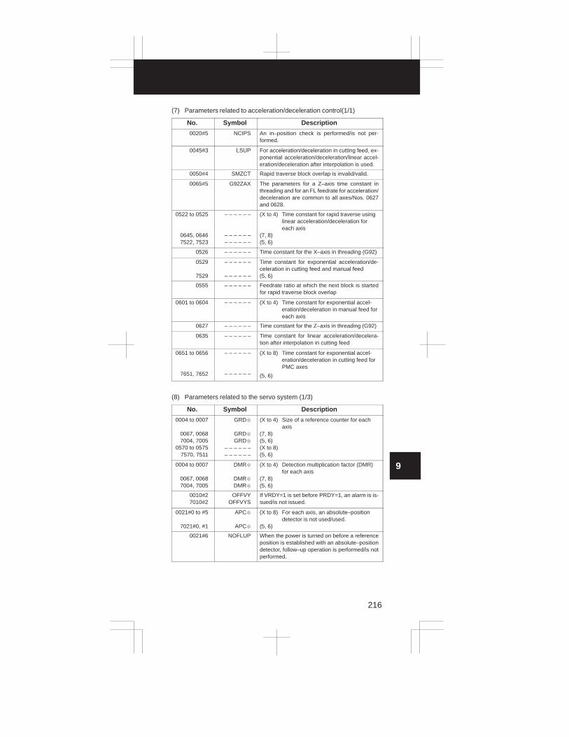
3
1
4
5
6
7
8
9
10
2
216
(7) Parameters related to acceleration/deceleration control(1/1)
No. Symbol Description
0020#5 NCIPS An in–position check is performed/is not per-formed.
0045#3 LSUP For acceleration/deceleration in cutting feed, ex-ponential acceleration/deceleration/linear accel-eration/deceleration after interpolation is used.
0050#4 SMZCT Rapid traverse block overlap is invalid/valid.
0065#5 G92ZAX The parameters for a Z–axis time constant inthreading and for an FL feedrate for acceleration/deceleration are common to all axes/Nos. 0627and 0628.
0522 to 0525
0645, 06467522, 7523
– – – – – –
– – – – – –– – – – – –
(X to 4) Time constant for rapid traverse usinglinear acceleration/deceleration foreach axis
(7, 8)(5, 6)
0526 – – – – – – Time constant for the X–axis in threading (G92)
0529
7529
– – – – – –
– – – – – –
Time constant for exponential acceleration/de-celeration in cutting feed and manual feed(5, 6)
0555 – – – – – – Feedrate ratio at which the next block is startedfor rapid traverse block overlap
0601 to 0604 – – – – – – (X to 4) Time constant for exponential accel-eration/deceleration in manual feed foreach axis
0627 – – – – – – Time constant for the Z–axis in threading (G92)
0635 – – – – – – Time constant for linear acceleration/decelera-tion after interpolation in cutting feed
0651 to 0656
7651, 7652
– – – – – –
– – – – – –
(X to 8) Time constant for exponential accel-eration/deceleration in cutting feed forPMC axes
(5, 6)
(8) Parameters related to the servo system (1/3)
No. Symbol Description
0004 to 0007
0067, 00687004, 7005
0570 to 05757570, 7511
GRD�
GRD�
GRD�
– – – – – –– – – – – –
(X to 4) Size of a reference counter for eachaxis
(7, 8)(5, 6)(X to 8)(5, 6)
0004 to 0007
0067, 00687004, 7005
DMR�
DMR�
DMR�
(X to 4) Detection multiplication factor (DMR)for each axis
(7, 8)(5, 6)
0010#27010#2
OFFVYOFFVYS
If VRDY=1 is set before PRDY=1, an alarm is is-sued/is not issued.
0021#0 to #5
7021#0, #1
APC�
APC�
(X to 8) For each axis, an absolute–positiondetector is not used/used.
(5, 6)
0021#6 NOFLUP When the power is turned on before a referenceposition is established with an absolute–positiondetector, follow–up operation is performed/is notperformed.

9. PARAMETERS For T series
217
(8) Parameters related to the servo system (2/3)
No. Symbol Description
0022#0 to #5
7022#0, #1
ABS�
ABS�
(X to 8) A reference position is not estab-lished/is already established with anabsolute–position detector.
(5, 6)
0035#77035#7
ACMRACMRS
(X to 8) An arbitrary CMR is not used/is used.(5, 6)
0035#77035#7
ACMRACMRS
(X to 8) An arbitrary CMR is not used/is used.(5, 6)
0037#0 to #5
7037#0, #1
SPTP�
SPTP�
(X to 8) As a position detector, a separatepulse coder is not used/is used.
(5, 6)
0037#7
7037#7
PLCO1
PLCO1S
(X to 8) A high–resolution pulse coder is notused/is used.
(5, 6)
0041#1 THRDB The threading start type is type A/type B.
0076#4 ADBLS Cutting feed and rapid traverse separate back-lash compensation is invalid/valid.
0389#3 TSKECR When the torque limit skip function is used, theservo error present at the time of skipping is re-covered/not recovered.
0390#0 to #5 NREQ� When a reference position is not establishedupon power–up, an alarm is issued/is not issuedto request reference position return when an ab-solute pulse coder is used for each axis.
0399#4 FUNO When a servo alarm is detected by the CNC, fol-low–up operation is performed/is not performed.
0100 to 0103
0275, 02767100, 7101
– – – – – –
– – – – – –– – – – – –
(X to 4) Command multiplication factor (CMR)for each axis
(7, 8)(5, 6)
0255 – – – – – – Time interval for averaged current value displayon the servo adjustment screen
0269 to 0274 – – – – – – Servo axis number
0452 to 0457
0739 to 07420827, 08287580, 75817739, 7740
– – – – – –
– – – – – –– – – – – –– – – – – –– – – – – –
(X to 8 3RD WORD) Counter value at the APC ref-erence position (X to 4 LOWER 2 WORD)(7, 8 LOWER 2 WORD)(5, 6 3RD WORD)(5, 6 LOWER 2 WORD)
0500 to 05030637, 06387500, 7501
– – – – – –– – – – – –– – – – – –
(X to 4) In–position width for each axis (7, 8)(5, 6)
0504 to 0507
0639, 06407504, 7505
– – – – – –
– – – – – –– – – – – –
(X to 4) Limit of position deviation duringmovement along each axis
(7, 8)(5, 6)
0508 to 05110641, 06427508, 7509
– – – – – –– – – – – –– – – – – –
(X to 4) Grid shift for each axis (7, 8)(5, 6)
0512 to 0515
0517
0632, 0633
7517
– – – – – –
– – – – – –
– – – – – –
– – – – – –
(X to 4) Position control loop gain for eachaxis
(X to 8) Position control loop gain common toall axes
(7, 8) Position control loop gain for eachaxis
(5, 6)

3
1
4
5
6
7
8
9
10
2
218
(8) Parameters related to the servo system (3/3)
No. Symbol Description
0535 to 05380647, 06487535, 7536
– – – – – –– – – – – –– – – – – –
(X to 4) Backlash compensation for each axis (7, 8)(5, 6)
0593 to 0596
0649, 06507593, 7594
– – – – – –
– – – – – –– – – – – –
(X to 4) Limit of position deviation in the stopstate for each axis
(7, 8)(5, 6)
0673 to 0678 – – – – – – (X to 4) Rapid traverse backlash compensationvalue for each axis
(9) Parameters related to DI/DO (1/1)
No. Symbol Description
0001#2 DCS The signal from the START button on the MDIpanel is routed/not routed via the machine.
0001#5
7001#5
DECI
DECIS
(X to 4) The deceleration signal for referenceposition return starts decelerationwhen this bit is set to 0/1.
(5, 6)
0003#4
7003#4
OVRI
OVRIS
(X to 4) The override signal and rapid traverseoverride signal increase speed whenthis bit is set to 0/1.
(5, 6)
0008#7 EILK The start lock signal is common to all axes/de-fined for each axis.
0009#0 to #3
7009#0 to #3
TFIN
TFIN
(X to 4) Acceptance time width for the M, S, orT function completion signal (G120#3FIN)
(5, 6)
0009#4 to #7
7009#4 to #7
TMF
TMF
(X to 4) Time before the M, S, or T functioncode read signal is sent
(5, 6)
0024#7 EDILK The interlock signal for each axis direction is in-valid/valid.
0031#5 ADDCF The PMC address for the GR1, GR2, and DRNsignals is G0118/G0123.
0038#0 DEC34 The PMC addresses for the *DEC3 and *DEC4signals are GX19#7 and X19#5/G16#7 andG17#7.
0041#3 ROVC The rapid traverse override signals are ROV andROV2/ROV1D, ROV2D, and ROV3D.
0045#2 RWDOUT The rewind in–progress signal (F164#6 RWD) isoutput only while the tape reader is being re-wound/while programs in memory are being re-wound.
0045#7 HSIF M, S, T, and B code processing is performed us-ing an ordinary/high–speed interface.
0070#4 DSTBGE When output is started in background editing, themanual data input start signal (F150#5 DST) isoutput/is not output.
0394#6 POSILK The start lock signal is invalid/valid for manualfeed.
0113, 0114 – – – – – – Position signal output grid number for each axis
0252 – – – – – – Reset signal extension time
0713, 0714 – – – – – – Position signal output grid width for each axis
0743 to 0746 – – – – – – Distance to a contact surface for each axis

9. PARAMETERS For T series
219
(10) Parameters related to CRT/MDI, display, and editing (1/3)
No. Symbol Description
0001#1 PROD Tool length compensation data is included/is notincluded in relative coordinate display.
0002#17002#1
PPDPPDS
Relative coordinates are not preset/are preset bycoordinate system setting.
0010#1 EBCL When programs stored in memory are displayed,the EOB code is displayed using ;/�.
0011#7 MCINP Programs are not stored/are stored in memorywith G117#0 MINP.
0013#4 INHMN Menu display is performed/not performed.
0014#2 STDP The actual speed of the spindle, S codes, and Tcodes are not displayed/are displayed.
0015#0 CBLNK The cursor blinks/does not blink.
0015#1 NWCH When tool wear compensation values are dis-played, the character W is displayed/is not dis-played.
0015#6 REP If the same program number is already containedin memory when programs are registered via thereader/punch interface, an alarm is issued/theprogram is replaced.
0018#7 EDITB The type of editing using the standard keyboardis edit operation A/B.
0019#6 NEOP When a program is registered, M02, M30, or M99ends/does not end registration.
0019#7 DBCD When the diagnostic screen is displayed, timerand counter data are displayed in binary/deci-mal.
0023#0 to #6 ���� Display language setting
0028#0 PRCPOS On the program check screen, relative/absolutecoordinates are displayed.
0028#2 DACTF Actual speed is not displayed/is displayed.
0028#3 MMDL In MDI operation B, the modal state is not dis-played/is displayed.
0029#0, #1 DSP� The current position of the third/fourth axis is notdisplayed/is displayed.
0029#6 DSPSUB The fifth/sixth axis is not displayed/is displayedon the absolute/relative position display screen.
0038#3 FLKY The keyboard of the CRT unit or MDI panel em-ploys the standard keys/full keypad.
0040#0 NAMPR Program names are not displayed/are displayedin the program directory.
0040#4 SORT The program directory is displayed in the order ofprogram registration/in the ascending order ofprogram numbers.
0045#0 RDL During external control of input/output units, readoperation follows the specification of No. 0015#6REP/registration is performed after deletion of allprograms.
0045#1 RAL In reading via the reader/punch interface, all pro-grams are registered/only the first program is reg-istered.
0048#7 SFFDSP Soft keys are displayed and controlled accordingto the additional option function specification/re-gardless of the additional option function specifi-cation.

3
1
4
5
6
7
8
9
10
2
220
(10) Parameters related to CRT/MDI, display, and editing (2/3)
No. Symbol Description
0050#1 NOFMK In sequence number search, a format check isperformed/is not performed.
0056#0 NOCND When the part program storage length is 120m/320 m, or when the background edit functionis provided, automatic memory compression isperformed/is not performed.
0057#0 PWNNC The MMC/CNC screen is displayed when thepower is turned on.
0057#1 ALMNC When an alarm is issued on the CNC duringMMC screen display, the MMC/CNC screen isdisplayed.
0057#2 SALNC When a system alarm is issued on the CNC dur-ing MMC screen display, the MMC/CNC screenis displayed.
0060#0 DADRDP Addresses are not displayed/are displayed onthe diagnostic screen.
0060#2 LDDSPG Dynamic ladder display is not performed/is per-formed.
0060#3 C14DGN When the 14–inch CRT unit is used, the diagnos-tic screen is displayed in the 9–inch/14–inch for-mat.
0060#5 OPMNDP Operating monitor display is invalid/valid.
0060#6 EXTSP The display and search operations are disabled/enabled for protected programs.
0060#7 IGNCOL When the 9–inch high–resolution CRT unit isused, a monochrome/color display is used.
0061#6 DSP78 For current position display using absolute andrelative coordinates, the seventh and eighthaxes are not displayed/are displayed.
0063#0 MTDSPI Output system/input system for machine coordi-nate display
0063#1 PRSTIN For automatic coordinate system setting basedon inch input, No. 0708 and up/No. 0815 and upare used.
0064#0 SETREL For relative coordinate presetting, the relativecoordinates are cleared to 0/preset to arbitraryvalues.
0064#1 ALLPRE For relative coordinate presetting, the standardspecification is used/axis selection is performedusing numeric keys.
0064#3 IOMDGN On the diagnostic screen, I/O link and extendedR/D area DI/DO display are not provided/are pro-vided.
0064#5 NPA When an alarm is issued or an operator messageis entered, the screen display switches/does notswitch to the alarm screen or message screen.
0066#0 ALL56 On the overall current position screen, the fifthand sixth axes are not displayed/are displayed.
0076#2 IOP NC program input and output operations can bestopped by resetting the NC/only by selecting the[STOP] soft key.
0077#2 SGP Servo waveform display is invalid/valid.
0077#6 HLKEY MDI key processing is/is not high–speed.
0078#0 NOINOW Input of a tool wear compensation value throughthe MDI keys is not prohibited/is prohibited.

9. PARAMETERS For T series
221
(10) Parameters related to CRT/MDI, display, and editing (3/3)
No. Symbol Description
0078#1 NOINOG Input of a tool geometry compensation valuethrough the MDI keys is not prohibited/is prohib-ited.
0078#2 NOINMV Input of macro variables through the MDI keys isnot prohibited/is prohibited.
0078#3 NOINWZ Input of an offset from the workpiece referencepoint through the MDI keys is not prohibited/isprohibited.
0389#0 SRVSET The servo setting screen is displayed/is not dis-played.
0393#2 WKNMDI In the automatic operation activation state/auto-matic operation stop state, input of an offset fromthe workpiece reference point through the MDIkeys is not prohibited/is prohibited.
0393#7 DGNWEB When PWE=0, PMC parameter input is prohib-ited/is not prohibited.
0394#7 CAKEY On the parameter, diagnostic, and offsetscreens, one–character cancellation using theCAN key is disabled/enabled.
0395#1 TLSCUR On the offset screen, the cursor position is notpreserved/is preserved.
0397#7 SERNAI The details of alarm 409 are not displayed/aredisplayed.
0257 to 0263 – – – – – – Tool post name (first to seventh characters) dis-played on the screen
0264 to 0267 – – – – – – Axis name subscript for each axis
0337 to 0346 – – – – – – Title character code
0351 to 0355 – – – – – – NC name character code
0550 – – – – – – Incremental value for automatic sequence num-ber insertion
0797 – – – – – – Password
0798 – – – – – – Key
(11) Parameters related to programs (1/2)
No. Symbol Description
0010#4 PRG9 The editing of subprograms O9000 to O9999 isnot prohibited/is prohibited.
0011#6 G01 Upon power–up, the G00/G01 mode is set.
0015#7 CPRD When the decimal point is omitted, the least inputincrement/mm, inch, deg, or sec unit is used.
0016#3 NPRD The decimal point input and display function isused/is not used.
0016#5 SPAG An angle for direct drawing dimension program-ming is specified by angle/supplementary angle.
0019#5 M02NR After M02 is executed, control returns/does notreturn to the start of the program.
0028#4 EXTS External workpiece number search/external pro-gram number search
0029#4 ADRC As a chamfering or corner R address, C or R/,Cor ,R is used.
0030#7 G91 Upon power–up, the G90/G91 mode is set.
0032#5 BLIN For B 8–digit input, 1.000 is always used/1.000(millimeter) or 1.0000 (inch) is used.

3
1
4
5
6
7
8
9
10
2
222
(11) Parameters related to programs (2/2)
No. Symbol Description
0036#1 GSP The G code system is of type A/type B.
0036#5 GSPC The G code system is of type B (A)/type C.
0040#2 MAPS Address Q for the pass point signal output func-tion cannot be used/can be used.
0040#5 TMCR The T code is for a tool function/for calling O9000.
0045#6 CLER The reset button, external reset signal, and emer-gency stop operation set the reset state/clearstate.
0057#7 MBCLR Upon reset, MDI–B programs are not cleared/arecleared.
0063#2 M198P M198 address P specifies a file number/programnumber.
0065#7 M3B One block can contain only one M code/up tothree M codes.
0389#2 PRG8 The editing of subprograms O8000 to O8999 isnot prohibited/is prohibited.
0391#7 NOCLR When the clear state is entered, certain G codesare cleared/are not cleared.
0393#3 M3RQNG The specification of a three–digit M code is valid/invalid.
0393#6 RADCHK When circular interpolation is specified, the dif-ference between the radius at the start point andthe radius at the end point is not checked/ischecked.
0395#0 DLG99 In the feed per rotation mode, a dwell commandis specified by time/spindle speed.
0396#7 EORRE If an EOR is read without reading a program endcode, an alarm is issued/the reset state is set.
0111, 0112 – – – – – – M code which performs no buffering
0243 – – – – – – Third digit (hundreds digit) of a wait M code
0248 – – – – – – M code for calling programs stored in a file
0554 – – – – – – Program number for parameters/macro vari-ables/diagnostic data
0587 – – – – – – M code for specifying spindle orientation
0588 – – – – – – M code for canceling spindle indexing
0589 – – – – – – Initial value of an M code used for spindle index-ing
0876 – – – – – – Arc radius error limit
(12) Parameters related to pitch error compensation (1/1)
No. Symbol Description
0011#0, #1
7011#0, #1
PML�
PML�S
(X to 4) Pitch error compensation magnifica-tion
(5, 6)
0756 to 0759
7713, 7714
– – – – – –
– – – – – –
(X to 4) Compensation interval in pitch errorcompensation for each axis
(5, 6)
1000 to 6000 – – – – – – Zero position for pitch error compensation foreach axis
1001 to 6128 – – – – – – Pitch error compensation for each axis

9. PARAMETERS For T series
223
(13) Parameters related to spindle control (1/3)
No. Symbol Description
0003#6, #7
0064#6, #7
PSG�
P2SG�
Gear ratio between the spindle and position cod-erGear ratio between the spindle and second posi-tion coder
0013#5 ORCW In orientation, S analog output is positive/nega-tive.
0013#6, #7 TCW, CWM Sign of S analog output
0024#2 SCTO The spindle speed arrival signal (G120#4 SAR)is not checked/is checked.
0028#7 PNOSMP The number of sampling operations for findingthe average spindle speed is 4/1.
0031#0 SNRL Upon reset, the spindle indexing mode is not can-celed/is canceled.
0031#1 SDRT The direction of spindle indexing with an M codeis positive/negative.
0049#0 EVSF When an S code is specified, the S code and SFare not output/are output at all times.
0049#2 CHKSP When SIND=1, spindle speed fluctuation detec-tion is disabled/enabled.
0062#3 SPMRPM The unit of parameter data for spindle speed con-trol is 1/10 [RPM].
0065#1 CZRN The first G00 command after the mode isswitched to the Cs contour control mode per-forms positioning after performing a referenceposition return/performs ordinary positioning.
0070#0, #1 DAC� For D/A conversion, the analog interface board isnot used/used.
0070#3 MSPDB The multi–spindle control method is type A/typeB.
0071#0 ISRLPC When a serial interface spindle is used, the posi-tion coder signal is received through an optical fi-ber/M27 connector.
0071#1 HISSC The sampling time for constant surface speedcontrol remains unchanged from the convention-al value/is the conventional value divided by 4.
0071#2 SRLMSP In multi–spindle control, the second axis is ana-log/serial.
0071#3 SSMPC M27/the second spindle control unit is used forthe second position coder.
0071#4 SRL2SP One/two serial interface spindles is/are con-nected.
0071#7 FSRSP Serial interface spindles are not used/are used.
0074#7 PLCREV A feedback pulse signal from a position coderrepresents an absolute value/is signed.
0080#2, #3 MORCM� For the first and second spindle motors, thespindle orientation function with the stop positionset externally is not used/is used.
0080#6, #7 SP�NEG During spindle synchronization, the rotationdirections of the first and second spindle motorsare the same as the specified sign/opposite tothe specified sign.
0108 – – – – – – Spindle speed when the spindle rotates at aconstant speed
0110 – – – – – – Delay timer used to check the spindle speed ar-rival signal (G120#4 SAR)

3
1
4
5
6
7
8
9
10
2
224
(13) Parameters related to spindle control (2/3)
No. Symbol Description
0249 – – – – – – Magnification for spindle speed ratio control overserial interface spindles
0303 – – – – – – Permissible pulse error for phase synchroniza-tion in the synchronized control mode
0381#7 IGNSIC A serial/analog spindle is connected to tool post2.
0397#0 SPLME The permissible rate and fluctuation rate of thespindle speed fluctuation detection function are1 [%]/0.1 [%].
0516 – – – – – – Data for gain adjustment in constant surfacespeed control (analog output)
0531 – – – – – – Permissible rate (Q) used in spindle speed fluc-tuation detection for determining whether a spe-cified speed is reached
0532 – – – – – – Spindle speed fluctuation rate (R) used in spindlespeed fluctuation detection for issuing an alarm
0539 – – – – – – Spindle speed offset value
0540 to 0543 – – – – – – Speed when the spindle speed command volt-age for each gear is 10 [V]
0546 – – – – – – Value for compensating for drift that occurred ina Cs–axis servo loop
0551 – – – – – – Minimum spindle speed in the constant surfacespeed control mode (G96)
0556 – – – – – – Maximum spindle speed for the constant surfacespeed control option
0564 – – – – – – Permissible speed fluctuation that does notcause an alarm to be issued in spindle speedfluctuation detection
0576 – – – – – – Permissible pulse error between two spindles inthe spindle (simple) synchronized control mode
0580 to 0583 – – – – – – Spindle servo loop gain multiplier in Cs–axiscontrol for each gear
0584 – – – – – – Spindle loop gain
0585 – – – – – – F0 feedrate for spindle rapid traverse override
0586 – – – – – – FL feedrate for spindle orientation
0587 – – – – – – M code for specifying spindle orientation
0588 – – – – – – M code for canceling spindle indexing
0589 – – – – – – Initial value of an M code used for spindle index-ing
0590 – – – – – – Basic angular displacement for spindle indexingusing an M code
0613 – – – – – – Data for second spindle gain adjustment inconstant surface speed control
0614 – – – – – – Spindle speed offset value for the second spindle
0615, 0616 – – – – – – Speed when the second spindle speed com-mand voltage for each gear is 10 [V]
0617 – – – – – – Data for third spindle gain adjustment in constantsurface speed control
0618 – – – – – – Spindle speed offset value for the third spindle
0619, 0620 – – – – – – Speed when the third spindle speed commandvoltage for each gear is 10 [V]
0712 – – – – – – Time before a spindle speed fluctuation check isstarted

9. PARAMETERS For T series
225
(13) Parameters related to spindle control (3/3)
No. Symbol Description
6780 to 6783 – – – – – – Position loop gain of a servo axis in the Cs con-tour control mode
6784 to 6787
6788 to 67916792 to 67956796 to 6799
– – – – – –
– – – – – –– – – – – –– – – – – –
(X) Position loop gain of a servo axis in the Cscontour control mode for each gear
(Y)(Z)(4)
7516 – – – – – – Data for gain adjustment in subspindle S4/S5digit control
7539 – – – – – – Subspindle speed offset value
(14) Parameters related to tool compensation (1/2)
No. Symbol Description
0001#3 TOC In the reset state, offset vectors are not canceled/are canceled.
0001#4 ORC For offset values, a diameter value/radius valueis specified.
0008#6 NOFC Offset values are loaded/are not loaded into acounter.
0010#5 DOFSI Direct input of tool offset values is not performed/is performed.
0013#1 GOFU2 A tool geometry compensation number is speci-fied using the least significant/most significantdigit of a T code.
0013#2 GMOFS Tool geometry compensation is performed byshifting the coordinate system/by moving thetool.
0013#3 GOFC Tool geometry compensation is not canceled/iscanceled by position number 0.
0014#0 T2D A T code is specified using 4 digits/2 digits.
0014#1 GMCL Tool geometry compensation is not canceled/iscanceled when the reset state is entered.
0014#4 OFSB Tool offsetting is performed in a block containinga T code/performed together with axis move-ment.
0014#5 WIGA A limit is not imposed/is imposed on tool offsetsetting.
0014#6 T2T4 When a T code is specified using 2 digits, the up-per 2 digits are assumed to be 00/are assumedto be the same as the lower 2 digits.
0015#4 MORB In direct input of measurement values, the recordbutton is not used/is used.
0024#6 QNI When tool compensation measurement direct in-put function B is used, a tool compensation num-ber is not selected/is selected automatically inthe offset write mode.
0036#3 YOF3 Y–axis offset is used with the fourth axis/thirdaxis.
0075#3 WNPT A virtual tool tip number for tool–tip radius com-pensation is specified using a geometric/wearcompensation number.
0122 – – – – – – Tool compensation number when the tool com-pensation measurement value direct input Bfunction is used

3
1
4
5
6
7
8
9
10
2
226
(14) Parameters related to tool compensation (2/2)
No. Symbol Description
0395#4 ADDLA During tool–tip radius compensation, if twoblocks specifying no movement are specifiedconsecutively, the offset vector is assumed to bethe vector perpendicular to the movement per-formed in the previous block at the end point/theintersection vector.
0557 – – – – – – Maximum ignorable travel distance along theoutside of a corner in tool–tip radius compensa-tion
0728 – – – – – – Maximum tool wear compensation value in incre-mental input
0729 – – – – – – Maximum tool wear compensation value
(15) Parameters related to canned cycles (1/1)
No. Symbol Description
0031#2 TAPM In a tapping cycle, M03 or M04/M05 is output inthe case of forward or reverse rotation.
0031#3 ILVL In a drilling cycle, the initial point is not updated/isupdated when a reset occurs.
0031#4 RTCT The peck drilling cycle is type A/B.
0393#1 MCQSCH In a multiple repetitive canned cycle for lathes, asequence number check with Q specified is notperformed/is performed.
0393#4 CHKMRC In a multiple repetitive canned cycle for lathes,specification of a pocket figure is valid/invalid.
0109 – – – – – – Cut width in threading cycle G92/G76
0204 – – – – – – M code for C–axis clamping in a drilling cannedcycle
0212, 0213 – – – – – – M code for forward spindle rotation/reversespindle rotation in a drilling canned cycle
0591 – – – – – – Dwell time used when C–axis unclamping is spe-cified in a drilling cycle
0592 – – – – – – Retract dimension (d) used for peck drilling in adrilling cycle
0717, 0718 – – – – – – Depth of cut/retract dimension in the multiple re-petitive canned cycles (G71, G72)
0719, 0720 – – – – – – Retract dimension for each axis in the multiple re-petitive canned cycle (G73)
0721 – – – – – – Number of divisions in the multiple repetitivecanned cycle (G73)
0722 – – – – – – Return distance in the multiple repetitive cannedcycles (G74, G75)
0723 – – – – – – Number of times finishing is performed in themultiple repetitive canned cycle (G76)
0724 – – – – – – Tool angle in the multiple repetitive canned cycle(G76)
0725 – – – – – – Minimum depth of cut in the multiple repetitivecanned cycle (G76)
0726 – – – – – – Finishing allowance in the multiple repetitivecanned cycle (G76)

9. PARAMETERS For T series
227
(16) Parameters related to rigid tapping (1/1)
No. Symbol Description
0029#3 RGCTO In rigid tapping, the time constant for accelera-tion/deceleration of the spindle and tapping axisduring withdraw are specified using the same pa-rameter as for cutting/using a separate parame-ter.
0041#0 RGTPE In rigid tapping, the rigid mode is canceled after/before the rigid DI signal is turned off.
0063#4 RGDOV Withdraw operation overriding is disabled/en-abled.
0063#6 VSLPC An arbitrary gear ratio is not used/is used be-tween the spindle and position coder.
0076#3 G84RGD G84 and G74 are not used/are used as G codesfor rigid tapping.
0397#3 RGMFH The feed hold and single block functions are en-abled/disabled.
0399#5 SIG In gear switching, the SIND signal is invalid/valid.
0214 to 0217 – – – – – – Spindle backlash distance in rigid tapping
0253 – – – – – – M code for specifying the rigid tapping mode
0254 – – – – – – Override value for withdraw in rigid tapping
0400 – – – – – – Tapping axis in–position width in rigid tapping
0401 – – – – – – Spindle in–position width in rigid tapping
0402 – – – – – – Limit on position deviation during movementalong the tapping axis
0403 – – – – – – Limit on position deviation during spindle move-ment
0404 – – – – – – Limit on position deviation while movementalong the tapping axis is stopped
0405 – – – – – – Limit on position deviation while spindle move-ment is stopped
04060407 to 0410
– – – – – – Loop gain for position control over the spindleand tapping axis (for each gear)
0411 to 0414 – – – – – – Spindle loop gain multiplier
0415 to 0418 – – – – – – Time constant for acceleration/deceleration forthe spindle and tapping axis
0419 to 0422 – – – – – – Time constant for acceleration/deceleration forthe spindle and tapping axis during withdraw
0423 to 0426 – – – – – – Maximum allowable spindle speed during rigidtapping
0427 to 0430 – – – – – – Number of teeth on the spindle side when an arbi-trary gear ratio is used
0431 to 0434 Number of teeth on the position coder side whenan arbitrary gear ratio is used
0435 – – – – – – Position deviation of the spindle during rigid tap-ping
0436 – – – – – – Amount of pulse distribution to the spindle duringrigid tapping
0473 – – – – – – Momentary error difference between the spindleand tapping axis
0483 – – – – – – Maximum error difference between the spindleand tapping axis

3
1
4
5
6
7
8
9
10
2
228
(17) Parameters related to custom macros (1/1)
No. Symbol Description
0011#5 SBKM A macro statement does not cause/causes asingle block stop.
0040#1 DPOSUP When data is output with the DPRINT command,spaces are output/no particular operation is per-formed for leading zeros.
0040#5 TMCR The T code is for a tool function/ for callingO9000.
0040#6 COMC Upon reset, common variables (#100 to #149)are placed/not placed in the null state.
0040#7 LOCC Upon reset, local variables (#01 to #33) areplaced/not placed in the null state.
0042 ASTCD Hole pattern corresponding to EIA code �
0043 EQCD Hole pattern corresponding to EIA code =
0044 SHPCD Hole pattern corresponding to EIA code #
0053 LBLCD Hole pattern corresponding to EIA code [
0054 RBLCD Hole pattern corresponding to EIA code ]
0056#1 MSKT When an interrupt is generated, absolute coordi-nates are not set/are set as skip coordinates.
0056#2 MBLK Custom macro interrupt type I/II
0056#3 MSTE The interrupt signal is based on the edge triggermethod/status trigger method.
0056#4 MPRM M codes for enabling and disabling an interruptare M96 and M97 respectively/determined by pa-rameter setting.
0056#5 MSUB The local variables used for an interrupt are mac-ro type/subprogram type.
0056#6 MCYL During cycle operation, the custom macro inter-rupt function is disabled/enabled.
0056#7 MUSR The custom macro interrupt function is disabled/enabled.
0057#4 CROUT Upon completion of ISO code data output by B/DPRINT, an LF code/CR and LF codes are output.
0218 – – – – – – Number of macro variables common to tool posts
0220 to 0229 – – – – – – G code for calling custom macros O9010 toO9019
0230 to 0239 – – – – – – M code for calling custom macros O9020 toO9029
0240 to 0242 – – – – – – M code for calling subprograms O9001 to O9003
0246 – – – – – – M code for enabling custom macro interrupts
0247 – – – – – – M code for disabling custom macro interrupts
0248 – – – – – – M code for calling programs stored in a file
(18) Parameters related to automatic tool compensation (1/1)
No. Symbol Description
0558 – – – – – – Feedrate used for measurement in automatictool compensation
0731, 0732 – – – – – – Value of � in automatic tool compensation
0733, 0734 – – – – – – Value of � in automatic tool compensation

9. PARAMETERS For T series
229
(19) Parameters related to graphic display (1/1)
No. Symbol Description
0024#3 GNSR The actual position with tool–tip radius com-pensation reflected is drawn/the programmedposition is drawn.
0046#5 GRPOS On the graphic display screen, the current posi-tion is not displayed/is displayed.
0123 – – – – – – Drawing coordinate system used with the graph-ic function
0630, 0631 – – – – – – Dot shift amount for 9–inch high–resolutiongraphic display
(20) Parameters related to run time/parts count display (1/1)
No. Symbol Description
0040#3 RWCNT With M02 or M30, the total number of machinedparts and the number of machined parts iscounted/is not counted.
0219 – – – – – – M code for counting the total number of machinedparts and the number of machined parts
0600 – – – – – – Number of required parts
0779 – – – – – – Total number of machined parts
(21) Parameters related to tool life management (1/1)
No. Symbol Description
0039#0, #1 GST� Number of groups that can be registered in toolgroup setting
0039#2 LCTM Tool life is specified by a count/time.
0039#3 TLSK When the tool skip signal (G140#0 TLSKP) is ap-plied, the group currently selected is skipped/thegroup number is also entered.
0039#4 GRST When the tool skip signal (G140#0 TLSKP) is ap-plied, the execution data of the group/executiondata of all groups is cleared.
0039#5 IGSK The tool skip signal (G140#0 TLSKP) is acceptedalways/only when a tool subject to tool life man-agement is being used.
0394#0 TLCSAM When multiple offset numbers are involved,counting is performed for each identical toolnumber/each tool.
0394#5 NOWOFS @ is prefixed/is not prefixed to a compensationnumber subject to tool life management.
0117 – – – – – – Offset number compensation value used with thesimplified tool life management function
0118 – – – – – – Tool selection number compensation value usedwith the simplified tool life management function
0119 – – – – – – Maximum offset number used with the simplifiedtool life management function
0120 – – – – – – Maximum tool selection number used with thesimplified tool life management function
0336 – – – – – – M code for restarting tool life count operation
0599 – – – – – – Tool life management ignore number

3
1
4
5
6
7
8
9
10
2
230
(22) Parameters related to the position switch function (1/1)
No. Symbol Description
0310 to 0319 – – – – – – Axis corresponding to a position switch
0840 to 0849 – – – – – – Maximum position switch operation range
0850 to 0859 – – – – – – Minimum position switch operation range
(23) Parameters related to manual handle feed/manual handle interrupt(1/1)
No. Symbol Description
0002#5 HSLE When two manual pulse generators are installed,the axis selection signal is invalid/valid.
0002#6 TJHD In the TEACH IN JOG mode, a manual pulse gen-erator is disabled/enabled.
0013#0 JHD In the JOG mode, a manual pulse generator isdisabled/enabled.
0075#2 INHND The unit of manual handle interrupt movement isthe output unit with acceleration/decelerationdisabled/is the input unit with the acceleration/deceleration enabled.
0077#4 HDLPM When the handle of a manual pulse generator isturned quickly, the scale indication and travel dis-tance may not match/the scale indication andtravel distance match.
0386#0 to #3 HPNEG� For each axis, the direction of manual handlefeed is the same/opposite.
0386#4 to #7 HDPIG� For each axis, the magnification (x 10000) ofmanual handle feed is used/is not used.
0121 – – – – – – Manual handle feed magnification (M)
0699 – – – – – – Manual handle feed magnification (specificationB)
(24) Parameters related to the software operator’s panel (1/1)
No. Symbol Description
0017#0 OPG1 On the software operator’s panel, mode selec-tion is not performed/is performed.
0017#1 OPG2 On the software operator’s panel, jog feed axisselection is not performed/is performed.
0017#2 OPG3 On the software operator’s panel, manual pulsegenerator axis selection and magnificationswitching are not performed/are performed.
0017#3 OPG4 On the software operator’s panel, jog feedrateoverride switching is not performed/is performed.
0017#4 OPG5 On the software operator’s panel, BDT, SBK,MLK, and DRN switching is not performed/is per-formed.
0017#5 OPG6 On the software operator’s panel, protect switch-ing is not performed/is performed.
0017#6 OPG7 On the software operator’s panel, feed holdswitching is not performed/is performed.
0130 to 0137 – – – – – – Jog feed axes and directions of the keys on thesoftware operator’s panel
0140 to 0203 – – – – – – Character codes of the general–purposeswitches on the software operator’s panel

9. PARAMETERS For T series
231
(25) Parameters related to restarting programs (1/1)
No. Symbol Description
0387#0 SQDNC In DNC operation, program restarting is disabled/enabled.
0124 to 0127 – – – – – – Order of movement to program restart positions
(26) Parameters related to high–speed cycle machining/high–speed remote buffers (1/1)
No. Symbol Description
0055#4 to #6 ITPCNT G05 data interpolation interval
0597 – – – – – – Number of high–speed remote buffer controlledaxes
(27) Parameters related to PMC–based axis control (1/2)
No. Symbol Description
0024#0 IGNPMC PMC–based axis control is enabled/disabled.
0032#47032#4
PNGMLKPNGMLKS
Machine locking along a PMC axis is enabled/disabled.
0032#6 EACSB PMC axis control is based on specification A/B.
0049#5 EFML10 A feedrate command (cutting feed) for PMC axiscontrol is multiplied by 1/10.
0052#0 to #7 NODIC� Current position display for PMC axis control fol-lows the decimal point position based on the set-ting unit 1/10/follows the standard specifications.
0061#0 to #5 EBC� For each axis, group A/B of the DI and DO signalsfor PMC axis control (specification B) is used.
0062#6 AXPCF Movement along a PMC controlled axis is added/is not added to actual speed display.
0063#57063#5
EAXOVEAXOVS
For PMC axes, the dry run and override functionsare disabled/enabled.
0066#3 EPMSKP In PMC–based axis control, the same skip signalused with the CNC/a separate signal is used.
0066#6, #7 ERVF� Magnification of a feedrate for feed–per–rotationin PMC axis control
0078#4 OVRIE In PMC axis control, the override signal in-creases speed when this bit is set to 0/1.
0078#6 RDRNE In PMC axis control, the dry run function cannot/can be used with a rapid traverse command.
0078#7 EAXOVE In PMC axis control, the dry run and override sig-nals are the same as those used with the CNC/separate dry run and override signals are used.
0387#7 EFERPD A rapid traverse rate in PMC axis control is speci-fied by the same parameter as with the CNC/spe-cified by the feedrate data of an axis control com-mand.
0350 – – – – – – Axis for which a feedrate is specified in PMC axiscontrol
0651 to 0656
7651, 7652
– – – – – –
– – – – – –
(X to 8) Time constant for exponential accel-eration/deceleration during cuttingfeed for a PMC axis
(5, 6)
0657 to 0662
7657, 7658
– – – – – –
– – – – – –
(X to 8) FL feedrate for exponential accelera-tion/deceleration during cutting feedfor a PMC axis
(5, 6)

3
1
4
5
6
7
8
9
10
2
232
(27) Parameters related to PMC–based axis control (2/2)
No. Symbol Description
0672 – – – – – – FL feedrate for reference position return opera-tion along a PMC controlled axis
0685 – – – – – – F0 feedrate for independent rapid traverse over-ride along a PMC controlled axis
0698 – – – – – – Maximum feedrate for feed per rotation along aPMC controlled axis
7021#6 SUB1 PMC axis control on the sub–CPU side is appliedto the fifth and sixth axes/the fifth axis only.
(28) Parameters related to cylindrical grinding machines (FS0/00–GCC)(1/1)
No. Symbol Description
0033#0 to #3 P1S� The skip signal used with G31 P1 is invalid/valid.
0033#4 to #7 P2S� The skip signal used with G31 P2 is invalid/valid.
0034#0 to #3 P3S� The skip signal used with G31 P3 is invalid/valid.
0034#4 to #7 P4S� The skip signal used with G31 P4 is invalid/valid.
0035#0 to #3 DS� The skip signal used with the dwell skip functionis invalid/valid.
0036#0 AGLST Slanted axis control is not exercised/is exer-cised.
0036#1 GSP The G code system is type A/type B.
0036#2 ZRTM1 Movement is performed/is not performed alongthe Z–axis in manual reference position returnoperation along the X–axis.
0036#4 G98 Upon power–up, the feed–per–rotation mode/feed–per–minute mode is set.
(29) Parameters related to the PMC (1/1)
No. Symbol Description
0028#1 PRCMSG The program check screen displays the remain-ing travel distance/message from the PMC.
0060#1 PCLDB The baud rate used for ladder loading is 4800[bps]/9600 [bps].
0070#6 PEXRD The R and D areas of the PMC–M are not ex-panded/are expanded.
0071#6 DPCRAM When a PMC RAM board is used, PMC LOADMENU is displayed/is not displayed.
0356 to 0359 – – – – – – Number of characters displayed in the remainingtravel distance field on the program check screen
0476 to 0479 – – – – – – Start PMC address where remaining travel dis-tance field characters are set

9. PARAMETERS For T series
233
(30) Parameters related to the butt–type reference position setting function(1/1)
No. Symbol Description
0372 to 0375 – – – – – – Torque limit value during execution of a butt–typereference position setting cycle
0451, 0458 – – – – – – Butting speed used when a butt–type referenceposition setting cycle is executed
0459 to 0462 – – – – – – Speed for reference position setting when a butt–type reference position setting cycle is executed
0872 to 0875 – – – – – – Reference position setting distance used when abutt–type reference position setting cycle isexecuted
(31) Parameters related to the DNC (1/1)
No. Symbol Description
0387#0 SQDNC In DNC operation, program restart is disabled/en-abled.
0390#7 NODC3 In DNC operation, reading is performed block byblock/until the buffer becomes full.
0396#0 BCC A BCC value check is performed/is not per-formed.
0396#2 NCKER An ER (RS–232–C) or TR (RS–422) check is per-formed/is not performed.
0396#3 ERCODE A 4–digit hexadecimal error code is not added/isadded to a negative acknowledgement.
0347 – – – – – – Mode of connection between the CNC and hostwhen the DNC1 interface is used
0348 – – – – – – CNC station address when the DNC1 interface isused
0365 – – – – – – Time–out period for the no–response timer
0366 – – – – – – Time–out period for the EOT signal timer
0368 – – – – – – Maximum invalid data count value
0369 – – – – – – Maximum number of message retransmissionsdue to NAK
0370 – – – – – – Maximum number of characters receivable aftertransmission termination processing
0490 – – – – – – Maximum datagram (data section) length

3
1
4
5
6
7
8
9
10
2
234
(32) Parameters related to the M–NET (1/1)
No. Symbol Description
0392#2 SRL1 The M–NET character length is 7/8 bits.
0392#4 SRPE An M–NET vertical parity check is not performed/is performed.
0392#5 SREP The M–NET vertical parity is odd/even.
0392#7 SRS2 The number of M–NET stop bits is 1/2.
0360 – – – – – – M–NET DI byte length
0361 – – – – – – M–NET DO byte length
0362 – – – – – – M–NET station address
0363 – – – – – – M–NET baud rate
0464 – – – – – – Timer monitoring value after a connection prepa-ration sequence for the local station is completed
0465 – – – – – – Polling time monitoring value for an ordinary se-quence for the local station
0466 – – – – – – Timer monitoring value from start of SAI trans-mission to completion of BCC transmission
0467 – – – – – – Timer value from completion of reception to startof transmission
0468 – – – – – – Output destination address for the spindleorientation signal
(33) Parameters related to the Cf–axis (1/1)
No. Symbol Description
0031#6 ESFC In the turning mode, a feedback pulse signal froma position detector is invalid/valid.
0031#7 CNRST In reference position return operation, a relativecoordinate along the Cf–axis is not cleared/iscleared.
0032#7 ROT10 The parameter unit for inch output is 0.1 [deg/min]/1 [deg/min].
(34) Parameters related to 2–path lathes (TT) (1/2)
No. Symbol Description
0046#0 RSTSW The reset key is enabled for both tool posts/onlyone selected tool post.
0046#1 SBAB On the common screen, tool post 2/tool post 1 isdisplayed on the upper side of the screen.
0046#2 IGNAL When an alarm is issued on a tool post, the feedhold state is set/is not set.
0047#0 TIST The tool post selection signal is valid/invalid.
0047#1 SP2C Graphic drawing is common to both tool posts/varies for each tool post.
0047#2 SEPH Output destination of the manual handle pulsesignal
0047#3 2SP The number of spindles is 1/2.
0047#4 M3LMT A wait M code is specified by No. 0243+100/Nos.0243 to 999.
0047#5, #6 VR� Start number of custom macro variables com-mon to tool posts
0048#0, #1 TY� Tool post coordinate system relationship
0048#2 ITO Tool post interference check method

9. PARAMETERS For T series
235
(34) Parameters related to 2–path lathes (TT) (2/2)
No. Symbol Description
0048#3 IFM In the manual mode, a tool post interferencecheck is not performed/is performed.
0048#4 IFE A tool post interference check is performed/is notperformed when satisfactory conditions are pres-ent.
0048#5 ZCLR A tool post interference check along the Z–axisis performed/is not performed.
0049#3 WTRDY PRDY is output with the timing specific to eachtool post/simultaneously.
0075#1 STHRD Simultaneous feed per rotation and threading onboth tool posts is impossible/is possible.
0381#7 IGNSIC A serial/analog spindle is connected to tool post2.
0383#6 FE34 On tool post 2, Cf–axis and Y–axis control is notexercised/is exercised.
0383#7 FEPA On tool post 2, PMC axis control is not exercised/is exercised.
0384#6 FESS A serial spindle is not connected/is connected totool post 2.
0384#7 FECS On tool post 2, Cs–axis control is not exercised/isexercised.
0385#7 MEMEX On tool post 2, the part program storage length isnot expanded/is expanded.
0397#4 SPCCK Balance cut threading with one spindle on twotool posts is disabled/enabled.
0397#5, #6 BOVR� Balance cut override
0218 – – – – – – Number of macro variables common to tool posts
0243 – – – – – – Third digit (hundreds digit) of a wait M code
0249 – – – – – – Magnification for controlling the spindle speedratio of serial interface spindles
0257 to 0263 – – – – – – Tool post name (first to seventh characters) dis-played on the screen
0264 to 0267 – – – – – – Axis name subscript for each axis
0598 – – – – – – Minimum program number shared by the toolposts
0730 – – – – – – Coordinate system shift distance between thetool posts
0768, 0769 – – – – – – Distance between the reference point of tool post1 and the reference point of tool post 2 for eachaxis
(35) Parameters related to polygon turning (1/2)
No. Symbol Description
0069#0 PLGN3 The third axis is not set/is set as a synchronizedaxis for polygon turning.
0069#1 PLGN4 The fourth axis is not set/is set as a synchronizedaxis for polygon turning.
0069#2 PLG7 The seventh axis is not set/is set as a synchro-nized axis for polygon turning.
0069#3 PLG8 The eighth axis is not set/is set as a synchro-nized axis for polygon turning.

3
1
4
5
6
7
8
9
10
2
236
(35) Parameters related to polygon turning (2/2)
No. Symbol Description
0069#7 PLHZ Reference position return operation along a syn-chronized axis with G28 is performed by rapidtraverse/always at low speed.
0667 – – – – – – Maximum allowable speed of a synchronizedaxis
0668 – – – – – – Speed of a synchronized axis
0669 – – – – – – Jog feedrate when the rotary switch for a syn-chronized axis is positioned at 10
0670 – – – – – – F0 feedrate for rapid traverse override of a syn-chronized axis
0671 – – – – – – FL feedrate for reference position return along asynchronized axis
0778 – – – – – – Travel distance per synchronized axis rotation
(36) Parameters related to synchronized control/axis recomposition (1/1)
No. Symbol Description
0380#0 to #5 SMR� Synchronized control with mirror image on is notexercised/is exercised.
0380#6 SPERR An acceleration/deceleration difference is notadded/is added to an out–of–sync distance insynchronized axis recomposition.
0380#7 NRST Synchronized axis recomposition is canceled/isnot canceled upon reset.
0381#0 to #5 SER� If an excessive position deviation occurs in syn-chronized axis recomposition, an alarm is not is-sued/is issued.
0382#0 to #5 PKU� When parking is performed during synchronizedaxis recomposition, absolute and relative coordi-nates are not updated/are updated.
0383#0 to #5 MPM� When synchronized axis recomposition isstarted, a workpiece coordinate system is notset/is set automatically.
0384#0 to #5 MPS� At the end of synchronized axis recomposition,the workpiece coordinate system is not reset/isreset to the original one.
0385#0 to #5 MCD� Axis recomposition with mirror image on is notperformed/is performed.
0320 to 0323 – – – – – – Master axis with which each axis is synchronized
0326 to 0329 – – – – – – Axis of tool post 1 for which the axis of tool post2 is used to perform axis recomposition
0686 to 0691 – – – – – – Limit on position deviation difference in synchro-nized control where each axis serves as a slaveaxis
0692 to 0697 – – – – – – Position deviation difference in synchronizedcontrol where each axis serves as a slave axis
0860 to 0865 – – – – – – Reference position coordinates in the coordinatesystem in axis recomposition for each axis

10. ALARM LIST For M series
237
(1) Program errors (P/S alarm)
(a) M series
Number Message Contents
000 PLEASE TURNOFF POWER
A parameter which requires the power off wasinput, turn off power.
001 TH PARITYALARM
TH alarm (A character with incorrect parity wasinput). Correct the tape.
002 TV PARITYALARM
TV alarm (The number of characters in a blockis odd). This alarm will be generated only whenthe TV check is effective.
003 TOO MANY DIGITS
Data exceeding the maximum allowable num-ber of digits was input. (Refer to the item of max.programmable dimensions.)
004 ADDRESS NOTFOUND
A numeral or the sign “ – ” was input without anaddress at the beginning of a block. Modify theprogram .
005 NO DATA AFTERADDRESS
The address was not followed by the appropri-ate data but was followed by another address orEOB code. Modify the program.
006 ILLEGAL USE OFNEGATIVE SIGN
Sign “ – ” input error (Sign “ – ” was input after anaddress with which it cannot be used. Or two ormore “ – ” signs were input.) Modify the program.
007 ILLEGAL USE OFDECIMAL POINT
Decimal point “ . ” input error (A decimal pointwas input after an address with which it can notbe used. Or two decimal points were input.)Modify the program.
009 ILLEGAL ADDRESS INPUT
Unusable character was input in significantarea.Modify the program.
010 IMPROPER G–CODE
An unusable G code or G code corresponding tothe function not provided is specified. Modifythe program.
011 NO FEEDRATECOMMANDED
Feedrate was not commanded to a cutting feedor the feedrate was inadequate. Modify the pro-gram.
014 ILLEGAL LEADCOMMAND
In variable lead threading, the lead incrementaland decremental outputted by address K ex-ceed the maximum command value or a com-mand such that the lead becomes a negativevalue is given.Modify the program.
015 TOO MANY AXESCOMMANDED
An attempt was made to move the machinealong the axes, but the number of the axes ex-ceeded the specified number of axes controlledsimultaneously. Alternatively, in a block wherewhere the skip function activated by the torque–limit reached signal (G31 P99/P98) was speci-fied, either moving the machine along an axiswas not specified, or moving the machine alongmultiple axes was specified. Specify move-ment only along one axis.
020 OVER TOLERANCE OFRADIUS
In circular interpolation (G02 or G03), differenceof the distance between the start point and thecenter of an arc and that between the end pointand the center of the arc exceeded the valuespecified in parameter No. 3410.
021 ILLEGAL PLANEAXIS COMMAN-DED
An axis not included in the selected plane (byusing G17, G18, G19) was commanded in circu-lar interpolation. Modify the program.

3
1
4
5
6
7
8
9
10
2
238
Number ContentsMessage
023 ILLEGAL RADIUSCOMMAND
In circular interpolation by radius designation,negative value was commanded for address R.Modify the program.
028 ILLEGAL PLANESELECT
In the plane selection command, two or moreaxes in the same direction are commanded.Modify the program.
029 ILLEGAL OFFSETVALUE
The offset values specified by T code is toolarge.Modify the program.
030 ILLEGAL OFFSETNUMBER
The offset number in T function specified for tooloffset is tool large.Modify the program.
031 ILLEGAL P COMMAND IN G10
In setting an offset amount by G10, the offsetnumber following address P was excessive or itwas not specified.Modify the program.
032 ILLEGAL OFFSETVALUE IN G10
In setting an offset amount by G10 or in writingan offset amount by system variables, the offsetamount was excessive.
033 NO SOLUTION ATCRC
A point of intersection cannot be determined fortool nose radius compensation. Modify the pro-gram.
034 NO CIRC AL-LOWED IN ST–UP/EXT BLK
The start up or cancel was going to be per-formed in the G02 or G03 mode in tool nose ra-dius compensation. Modify the program.
035 CAN NOT COMMANDEDG31
Skip cutting (G31) was specified in tool nose ra-dius compensation mode. Modify the program.
037 CAN NOTCHANGE PLANEIN NRC
The offset plane is switched in tool nose radiuscompensation.Modify the program.
038 INTERFERENCEIN CIRCULARBLOCK
Overcutting will occur in tool nose radius com-pensation because the arc start point or endpoint coincides with the arc center. Modify the program.
039 CHF/CNR NOT AL-LOWED IN NRC
Chamfering or corner R was specified with astart–up, a cancel, or switching between G41and G42 in tool nose radius compensation. Theprogram may cause overcutting to occur inchamfering or corner R. Modify the program.
040 INTERFERENCEIN G90/G94BLOCK
Overcutting will occur in tool nose radius com-pensation in canned cycle G90 or G94. Modifythe program.
041 INTERFERENCEIN NRC
Overcutting will occur in tool nose radius com-pensation.Modify the program.
046 ILLEGAL REF-ERENCE RETURNCOMMAND
Other than P2, P3 and P4 are commanded for2nd, 3rd and 4th reference position return com-mand.
050 CHF/CNR NOT AL-LOWED IN THRDBLK
Chamfering or corner R is commanded in thethread cutting block.Modify the program.
051 MISSING MOVEAFTER CHF/CNR
Improper movement or the move distance wasspecified in the block next to the chamfering orcorner R block.Modify the program.
052 CODE IS NOT G01AFTER CHF/CNR
The block next to the chamfering or corner Rblock is not G01.Modify the program.

10. ALARM LIST For M series
239
Number ContentsMessage
053 TOO MANY ADDRESS COMMANDS
In the chamfering and corner R commands, twoor more of I, K and R are specified. Otherwise,the character after a comma(”,”) is not C or R indirect drawing dimensions programming.Modify the program.
054 NO TAPER ALLOWED AFTERCHF/CNR
A block in which chamfering in the specifiedangle or the corner R was specified includes ataper command. Modify the program.
055 MISSING MOVEVALUE IN CHF/CNR
In chamfering or corner R block, the move dis-tance is less than chamfer or corner R amount.
056 NO END POINT &ANGLE IN CHF/CNR
Neither the end point nor angle is specified inthe command for the block next to that for whichonly the angle is specified (A). In the chamfer-ing comman, I(K) is commanded for the X(Z)axis.
057 NO SOLUTION OFBLOCK END
Block end point is not calculated correctly in di-rect dimension drawing programming.
058 END POINT NOTFOUND
Block end point is not found in direct dimensiondrawing programming.
059 PROGRAM NUMBER NOTFOUND
In an external program number search, a speci-fied program number was not found. Otherwise,a program specified for searching is beingedited in background processing. Check theprogram number and external signal. Or discon-tinue the background eiting.
060 SEQUENCE NUMBER NOTFOUND
Commanded sequence number was not foundin the sequence number search. Check the se-quence number.
061 ADDRESS P/QNOT FOUND ING70–G73
Address P or Q is not specified in G70, G71,G72, or G73 command.Modify the program.
062 ILLEGAL COMMAND ING71–G76
1 The depth of cut in G71 or G72 is zero ornegative value.
2 The repetitive count in G73 is zero or neg-ative value.
3 the negative value is specified to ∆i or ∆kis zero in G74 or G75.
4 A value other than zero is specified to ad-dress U or W, though ∆i or ∆k is zero inG74 or G75.
5 A negative value is specified to ∆d,thoughthe relief direction in G74 or G75 isdetermined.
6. Zero or a negative value is specified to theheight of thread or depth of cut of first timein G76.
7 The specified minimum depth of cut in G76is greater than the height of thread.
8 An unusable angle of tool tip is specified inG76.
Modify the program.
063 SEQUENCE NUMBER NOTFOUND
The sequence number specified by address Pin G70, G71, G72, or G73 command cannot besearched. Modify the program.
064 SHAPE PROGRAM NOTMONOTONOUSLY
A target shape which cannot be made by mono-tonic machining was specified in a repetitivecanned cycle (G71 or G72).

3
1
4
5
6
7
8
9
10
2
240
Number ContentsMessage
065 ILLEGAL COMMAND ING71–G73
1 G00 or G01 is not commanded at the blockwith the sequence number which is speci-fied by address P in G71, G72, or G73command.
2. Address Z(W) or X(U) was commanded inthe block with a sequence number which isspecified by address P in G71 or G72, re-spectively.
Modify the program.
066 IMPROPER G–CODE IN G71–G73
An unallowable G code was commanded be-ween two blocks specified by address P in G71,G72, or G73. Modify the program.
067 CAN NOT ERRORIN MDI MODE
G70, G71, G72, or G73 command with addressP and Q.Modify the program.
068 MORE THAN 10POCKETS HAVEBEEN SPECIFIED.
More than 10 pockets have been specified astype II in a G71 or G72 code.
069 FORMAT ERRORIN G70–G73
the final move command in the blocks specifiedby P and Q of G70, G71, G72, and G73 endedwith chamfering or corner R. Modify the pro-gram.
070 NO PROGRAMSPACE INMEMORY
The memory area is insufficient.Delete any unnecessary programs, then retry.
071 DATA NOT FOUND The address to be searched was not found. Orthe program with specified program numberwas not found in program number search.Check the data.
072 TOO MANY PROGRAMS
The number of programs to be stored exceeded63 (basic), 125 (option), 200 (option), or 400 (op-tion). Delete unnecessary programs andexecute program registeration again.
073 PROGRAM NUMBER ALREADY IN USE
The commanded program number has alreadybeen used.Change the program number or delete unneces-sary programs and execute program registera-tion again.
074 ILLEGAL PRO-GRAM NUMBER
The program number is other than 1 to 9999.Modify the program number.
075 PROTECT An attempt was made to register a programwhose number was protected.
076 ADDRESS P NOTDEFINED
Address P (program number) was not comman-ded in the block which includes an M98, G65, orG66 command. Modify the program.
077 SUB PROGRAMNESTING ERROR
The subprogram was called in five folds. Modifythe program.
078 NUMBER NOTFOUND
A program number or a sequence number whichwas specified by address P in the block whichincludes an M98, M99, M65 or G66 was notfound. The sequence number specified by aGOTO statement was not found. Otherwise, acalled program is being edited in backgroundprocessing. Correct the program, or discontinuethe background editing.
079 PROGRAMVERIFY ERROR
In memory or program collation,a program inmemory does not agree with that read from anexternal I/O device. Check both the programs inmemory and those from the external device.

10. ALARM LIST For M series
241
Number ContentsMessage
080 G37 ARRIVAL SIG-NAL NOT ASSERTED
In the automatic tool compensation function(G36, G37), the measurement position reachsignal (XAE or ZAE) is not turned on within anarea specified in parameter 6254 (value ε). This is due to a setting or operator error.
081 OFFSET NUMBERNOT FOUND ING37
Automatic tool compensation (G36, G37) wasspecified without a T code. (Automatic tool com-pensation function) Modify the program.
082 T–CODE NOT ALLOWED IN G37
T code and automatic tool compensation (G36,G37) were specified in the same block. (Auto-matic tool compensation function) Modify the program.
083 ILLEGAL AXISCOMMAND IN G37
In automatic tool compensation (G36, G37), aninvalid axis was specified or the command is in-cremental. Modify the program.
085 COMMUNICATIONERROR
When entering data in the memory by usingReader / Puncher interface, an overrun, parity orframing error was generated. The number of bitsof input data or setting of baud rate or specifica-tion No. of I/O unit is incorrect.
086 DR SIGNAL OFF When entering data in the memory by usingReader / Puncher interface, the ready signal(DR) of reader / puncher was turned off.Power supply of I/O unit is off or cable is not con-nected or a P.C.B. is defective.
087 BUFFER OVERFLOW
When entering data in the memory by usingReader / Puncher interface, though the read ter-minate command is specified, input is not inter-rupted after 10 characters read. I/O unit orP.C.B. is defective.
090 REFERENCE RETURN INCOMPLETE
The reference position return cannot be per-formed normally because the reference positionreturn start point is too close to the referenceposition or the speed is too slow. Separate thestart point far enough from the reference posi-tion, or specify a sufficiently fast speed for refer-ence position return. Check the program con-tents.
091 MANUAL RETURNIMPOSSIBLEDURING PAUSE
A manual return to the reference position wasimpossible because of the program being atpause. Press the reset button to cause a manu-al return.
092 AXES NOT ONTHE REFERENCEPOINT
The commanded axis by G27 (Reference posi-tion return check) did not return to the referenceposition.
094 P TYPE NOT ALLOWED(COORD CHG)
P type cannot be specified when the program isrestarted. (After the automatic operation was in-terrupted, the coordinate system setting opera-tion was performed.)Perform the correct operation according to thoperator’s manual.
095 P TYPE NOT ALLOWED (EXT OFS CHG)
P type cannot be specified when the program isrestarted. (After the automatic operation wasinterrupted, the external workpiece offsetamount changed.)Perform the correct operation according to thoperator’s manual.
096 P TYPE NOT ALLOWED (WRK OFS CHG)
P type cannot be specified when the program isrestarted. (After the automatic operation was in-terrupted, the workpiece offset amountchanged.)Perform the correct operation according to thoperator’s manual.

3
1
4
5
6
7
8
9
10
2
242
Number ContentsMessage
097 P TYPE NOT ALLOWED (AUTOEXEC)
P type cannot be directed when the program isrestarted. (After power ON, after emergencystop or P / S 94 to 97 reset, no automatic opera-tion is performed.) Perform automatic operation.
098 G28 FOUND INSEQUENCE RETURN
A command of the program restart was speci-fied without the reference position return opera-tion after power ON or emergency stop, and G28was found during search.Perform the reference position return.
099 MDI EXEC NOTALLOWED AFT.SEARCH
After completion of search in program restart, amove command is given with MDI.
100 PARAMETERWRITE ENABLE
On the PARAMETER(SETTING) screen,PWE(parameter writing enabled) is set to 1. Setit to 0, then reset the system.
101 PLEASE CLEARMEMORY
The power turned off while rewriting the memoryby program edit operation. If this alarm has oc-curred, press <RESET> while pressing<PROG>, and only the program being editedwill be deleted.Register the deleted program.
110 DATA OVERFLOW The absolute value of fixed decimal point dis-play data exceeds the allowable range. Modifythe program.
111 CALCULATEDDATA OVERFLOW
The result of calculation turns out to be invalid,an alarm No.111 is issued.–1047 to –10–29, 0, 10–29 to 1047
Modify the program.
112 DIVIDED BY ZERO Division by zero was specified. (including tan90°)Modify the program.
113 IMPROPER COMMAND
A function which cannot be used in custom mac-ro is commanded.Modify the program.
114 FORMAT ERRORIN MACRO
There is an error in other formats than <Formu-la>.Modify the program.
115 ILLEGAL VARIABLE NUMBER
A value not defined as a variable number is des-ignated in the custom macro or in high–speedcycle machining.The header contents are improper. This alarmis given in the following cases:
High speed cycle machining
1. The header corresponding to the specifiedmachining cycle number called is notfound.
2. The cycle connection data value is out ofthe allowable range (0 – 999).
3. The number of data in the header is out ofthe allowable range (0 – 32767).
4. The start data variable number of execut-able format data is out of the allowablerange (#20000 – #85535).
5. The last storing data variable number ofexecutable format data is out of the allow-able range (#85535).
6. The storing start data variable number ofexecutable format datais overlapped withthe variable number used in the header.
Modify the program.

10. ALARM LIST For M series
243
Number ContentsMessage
116 WRITE PROTECTED VARIABLE
The left side of substitution statement is a vari-able whose substitution is inhibited. Modify theprogram.
118 PARENTHESISNESTING ERROR
The nesting of bracket exceeds the upper limit(quintuple).Modify the program.
119 ILLEGAL ARGUMENT
The SQRT argument is negative. Or BCD argu-ment is negative, and other values than 0 to 9are present on each line of BIN argument.Modify the program.
122 DUPLICATE MAC-RO MODAL–CALL
The macro modal call is specified in double.Modify the program.
123 CAN NOT USEMACRO COM-MAND IN DNC
Macro control command is used during DNC op-eration.Modify the program.
124 MISSING ENDSTATEMENT
DO – END does not correspond to 1 : 1. Modifythe program.
125 FORMAT ERRORIN MACRO
<Formula> format is erroneous. Modify the pro-gram.
126 ILLEGAL LOOPNUMBER
In DOn, 1� n �3 is not established. Modify theprogram.
127 NC, MACROSTATEMENT INSAME BLOCK
NC and custom macro commands coexist.Modify the program.
128 ILLEGAL MACROSEQUENCE NUM-BER
The sequence number specified in the branchcommand was not 0 to 9999. Or, it cannot besearched. Modify the program.
129 ILLEGAL ARGUMENT ADDRESS
An address which is not allowed in <ArgumentDesignation > is used.Modify the program.
130 ILLEGAL AXIS OPERATION
An axis control command was given by PMC toan axis controlled by CNC. Or an axis controlcommand was given by CNC to an axis con-trolled by PMC. Modify the program.
131 TOO MANY EXTERNALALARM MESSAGES
Five or more alarms have generated in externalalarm message.Consult the PMC ladder diagram to find thecause.
132 ALARM NUMBERNOT FOUND
No alarm No. concerned exists in external alarmmessage clear.Check the PMC ladder diagram.
133 ILLEGAL DATA INEXT. ALARM MSG
Small section data is erroneous in externalalarm message or external operator message.Check the PMC ladder diagram.
135 SPINDLEORIENTATIONPLEASE
Without any spindle orientation , an attept wasmade for spindle indexing. Perform spindleorientation.
136 C/H–CODE &MOVE CMD INSAME BLK.
A move command of other axes was specifiedto the same block as spindle indexing address-es C, H. Modify the program.
137 M–CODE & MOVECMD IN SAMEBLK.
A move command of other axes was specifiedto the same block as M–code related to spindleindexing. Modify the program.
139 CAN NOTCHANGE PMCCONTROL AXIS
An axis is selected in commanding by PMC axiscontrol.Modify the program.

3
1
4
5
6
7
8
9
10
2
244
Number ContentsMessage
145 ILLEGAL CONDI-TIONS IN POLARCOORDINATE INTERPOLATION
The conditions are incorrect when the polarcoordinate interpolation starts or it is canceled.
1) In modes other than G40, G12.1/G13.1was specified.
2) An error is found in the plane selection.Parameters No. 5460 and No. 5461 areincorrectly specified.
Modify the value of program or parameter.
146 IMPROPER G CODE
G codes which cannot be specified in the polarcoordinate interpolation mode was specified.Modify the program.
150 ILLEGAL TOOLGROUP NUMBER
Tool Group No. exceeds the maximum allow-able value.Modify the program.
151 TOOL GROUPNUMBER NOTFOUND
The tool group commanded in the machiningprogram is not set.Modify the value of program or parameter.
152 NO SPACE FORTOOL ENTRY
The number of tools within one group exceedsthe maximum value registerable. Modify thenumber of tools.
153 T–CODE NOTFOUND
In tool life data registration, a T code was notspecified where one should be. Correct the pro-gram.
155 ILLEGAL T–CODEIN M06
In the machining program, M06 and T code inthe same block do not correspond to the groupin use. Correct the program.
156 P/L COMMANDNOT FOUND
P and L commands are missing at the head ofprogram in which the tool group is set. Correctthe program.
157 TOO MANY TOOLGROUPS
The number of tool groups to be set exceeds themaximum allowable value. Modify the program.
158 ILLEGAL TOOLLIFE DATA
The tool life to be set is too excessive. Modifythe setting value.
159 TOOL DATA SETTING INCOMPLETE
During executing a life data setting program,power was turned off. Set again.
160 MISMATCH WAT-ING M–CODE
(TT only)
Diffrent M code is commanded in heads 1 and2 as waiting M code.Modify the program.
163 COMMANDG68/G69 INDEPENDENTLY
(TT only)
G68 and G69 are not independently comman-ded in balance cut.Modify the program.
169 ILLEGAL TOOLGEOMETRY DATA
(TT only)
Incorrect tool figure data in interference check.
175 ILLEGAL G107COMMAND
Conditions when performing circular interpola-tion start or cancel not correct. Modify the program.

10. ALARM LIST For M series
245
Number ContentsMessage
176 IMPROPER G–CODE IN G107
Any of the following G codes which cannot bespecified in the cylindrical interpolation modewas specified.
1) G codes for positioning: G28, G76, G81 –G89, including the codes specifying therapid traverse cycle
2) G codes for setting a coordinate system:G50, G52
3) G code for selecting coordinate system:G53 G54–G59
Modify the program.
177 CHECK SUM ERROR(G05 MODE)
Check sum errorModify the program.
178 G05 COMMAN-DED IN G41/G42MODE
G05 was commanded in the G41/G42 mode.Correct the program.
179 PARAM. (NO.7510) SETTINGERROR
The number of controlled axes set by the param-eter (No. 597) exceeds the maximum number.Modify the parameter setting value.
180 COMMUNICATIONERROR (REMOTE BUF)
Remote buffer connection alarm has generated.Confirm the number of cables, parameters andI/O device.
194 SPINDLE COMMAND INSYNCHRO–MODE
A contour control mode, spindle positioning(Cs–axis control) mode, or rigid tapping modewas specified during the serial spindle synchronous control mode. Correct the programso that the serial spindle synchronous controlmode is released in advance.
195 SPINDLE CONTROL MODESWITCH
The serial spindle control mode was notswitched. Check the PMC ladder program.
197 C–AXIS COMMANDED INSPINDLE MODE
The program specified a movement along theCf–axis when the signal CON(DGN=G027#7)was off. Correct the program, or consult thePMC ladder diagram to find the reason the sig-nal is not turned on.
199 MACRO WORDUNDEFINED
Undefined macro word was used. Modify thecustom macro.
200 ILLEGAL S CODECOMMAND
In the rigid tap, an S value is out of the range oris not specified.The range for S values which can be specifiedin rigid tapping is set in parameter 5243.Change the setting in the parameter or modifythe program.
201 FEEDRATE NOTFOUND IN RIGIDTAP
In the rigid tap, no F value is specified.Correct the program.
202 POSITION LSIOVERFLOW
In the rigid tap, spindle distribution value is toolarge.
203 PROGRAM MISSAT RIGID TAPPING
In the rigid tap, position for a rigid M code (M29)or an S command is incorrect. Modify the pro-gram.
204 ILLEGAL AXIS OPERATION
In the rigid tap, an axis movement is specifiedbetween the rigid M code (M29) block and G84(G74) block. Modify the program.
205 RIGID MODE DISIGNAL OFF
Rigid mode DI signal is not ON when G84 (G74)is executed though the rigid M code (M29) isspecified.Consult the PMC ladder diagram tofind the reason the DI signal (DGNG061.1) is notturned on.
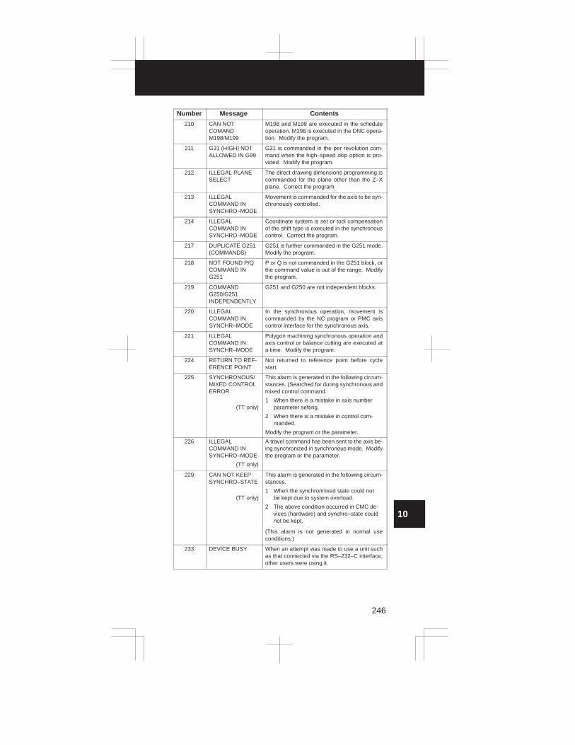
3
1
4
5
6
7
8
9
10
2
246
Number ContentsMessage
210 CAN NOT COMAND M198/M199
M198 and M199 are executed in the scheduleoperation. M198 is executed in the DNC opera-tion. Modify the program.
211 G31 (HIGH) NOTALLOWED IN G99
G31 is commanded in the per revolution com-mand when the high–speed skip option is pro-vided. Modify the program.
212 ILLEGAL PLANESELECT
The direct drawing dimensions programming iscommanded for the plane other than the Z–Xplane. Correct the program.
213 ILLEGAL COMMAND IN SYNCHRO–MODE
Movement is commanded for the axis to be syn-chronously controlled.
214 ILLEGAL COMMAND IN SYNCHRO–MODE
Coordinate system is set or tool compensationof the shift type is executed in the synchronouscontrol. Correct the program.
217 DUPLICATE G251(COMMANDS)
G251 is further commanded in the G251 mode.Modify the program.
218 NOT FOUND P/QCOMMAND ING251
P or Q is not commanded in the G251 block, orthe command value is out of the range. Modifythe program.
219 COMMANDG250/G251 INDEPENDENTLY
G251 and G250 are not independent blocks.
220 ILLEGAL COMMAND INSYNCHR–MODE
In the synchronous operation, movement iscommanded by the NC program or PMC axiscontrol interface for the synchronous axis.
221 ILLEGAL COMMAND INSYNCHR–MODE
Polygon machining synchronous operation andaxis control or balance cutting are executed ata time. Modify the program.
224 RETURN TO REF-ERENCE POINT
Not returned to reference point before cyclestart.
225 SYNCHRONOUS/MIXED CONTROLERROR
(TT only)
This alarm is generated in the following circum-stances. (Searched for during synchronous andmixed control command.
1 When there is a mistake in axis numberparameter setting.
2 When there is a mistake in control com-manded.
Modify the program or the parameter.
226 ILLEGAL COMMAND IN SYNCHRO–MODE
(TT only)
A travel command has been sent to the axis be-ing synchronized in synchronous mode. Modifythe program or the parameter.
229 CAN NOT KEEPSYNCHRO–STATE
(TT only)
This alarm is generated in the following circum-stances.
1 When the synchro/mixed state could notbe kept due to system overload.
2 The above condition occurred in CMC de-vices (hardware) and synchro–state couldnot be kept.
(This alarm is not generated in normal useconditions.)
233 DEVICE BUSY When an attempt was made to use a unit suchas that connected via the RS–232–C interface,other users were using it.

10. ALARM LIST For T series
247
(b) T series
Number Meaning Contents and remedy
000 PLEASE TURNOFF POWER
A parameter which requires the power off wasinput, turn off power.
001 TH PARITYALARM
TH alarm (A character with incorrect parity wasinput). Correct the tape.
002 TV PARITYALARM
TV alarm (The number of characters in a blockis odd). This alarm will be generated only whenthe TV check is effective.
003 TOO MANY DIGITS
Data exceeding the maximum allowable num-ber of digits was input. (Refer to the item of max.programmable dimensions.)
004 ADDRESS NOTFOUND
A numeral or the sign “ – ” was input without anaddress at the beginning of a block. Modify theprogram .
005 NO DATA AFTERADDRESS
The address was not followed by the appropri-ate data but was followed by another address orEOB code. Modify the program.
006 ILLEGAL USE OFNEGATIVE SIGN
Sign “ . ” input error (Sign “ – ” was input after anaddress with which it cannot be used. Or two ormore “ – ” signs were input.) Modify the program.
007 ILLEGAL USE OFDECIMAL POINT
Decimal point “ – ” input error (A decimal pointwas input after an address with which it can notbe used. Or two decimal points were input.)Modify the program.
008 ILLEGAL USE OFPROGRAM END
An attempt was made to execute EOR (%) be-cause there was not M02, M30, or M99 at theend of the program. Correct the program.
009 ILLEGAL AD-DRESS INPUT
Unusable character was input in significantarea.Modify the program.
010 IMPROPER G–CODE
An unusable G code or G code corresponding tothe function not provided is specified. Modifythe program.
011 NO FEEDRATECOMMANDED
Feedrate was not commanded to a cutting feedor the feedrate was inadequate. Modify the pro-gram.
014 CAN NOT COM-MAND G95
A synchronous feed is specified without the op-tion for threading / synchronous feed.
015 TOO MANY AXESCOMMANDED
The number of the commanded axes exceededthat of simultaneously controlled axes.
020 OVER TOLER-ANCE OF RADIUS
In circular interpolation (G02 or G03), differenceof the distance between the start point and thecenter of an arc and that between the end pointand the center of the arc exceeded the valuespecified in parameter No. 876.
021 ILLEGAL PLANEAXIS COMMAN-DED
An axis not included in the selected plane (byusing G17, G18, G19) was commanded in circu-lar interpolation. Modify the program.
025 CANNOT COMMAND F0 ING02/G03
F0 (fast feed) was instructed by F1 –digit col-umn feed in circular interpolation. Modify theprogram.
027 NO AXES COMMANDED ING43/G44
No axis is specified in G43 and G44 blocks forthe tool length offset type C.Offset is not canceled but another axis is offsetfor the tool length offset type C. Modify the pro-gram.

3
1
4
5
6
7
8
9
10
2
248
Number Contents and remedyMeaning
028 ILLEGAL PLANESELECT
In the plane selection command, two or moreaxes in the same direction are commanded.Modify the program.
029 ILLEGAL OFFSETVALUE
The offset values specified by H code is toolarge.Modify the program.
030 ILLEGAL OFFSETNUMBER
The offset number specified by D/H code for toollength offset or cutter compensation is too large.Modify the program.
031 ILLEGAL P COM-MAND IN G10
In setting an offset amount by G10, the offsetnumber following address P was excessive or itwas not specified.Modify the program.
032 ILLEGAL OFFSETVALUE IN G10
In setting an offset amount by G10 or in writingan offset amount by system variables, the offsetamount was excessive.
033 NO SOLUTION ATCRC
A point of intersection cannot be determined forcutter compensation C. Modify the program.
034 NO CIRC AL-LOWED IN ST–UP/EXT BLK
The start up or cancel was going to be per-formed in the G02 or G03 mode in cutter com-pensation. Modify the program.
035 CAN NOT COM-MANDED G39
G39 is commanded in cutter compensation Bcancel mode or on the plane other than offsetplane. Modify the program.
036 CAN NOT COM-MANDED G31
Skip cutting (G31) was specified in cutter com-pensation mode.Modify the program.
037 CAN NOTCHANGE PLANEIN CRC
G40 is commanded on the plane other than off-set plane in cutter compensation B. The planeselected by using G17, G18 or G19 is changedin cutter compensation C mode. Modify the pro-gram.
038 INTERFERENCEIN CIRCULARBLOCK
Overcutting will occur in cutter compensation Cbecause the arc start point or end point coin-cides with the arc center. Modify the program.
041 INTERFERENCEIN CRC
Overcutting will occur in cutter compensation C. Two or more blocks are consecutively specifiedin which functions such as the auxiliary functionand dwell functions are performed withoutmovement in the cutter compensation mode.Modify the program.
042 G45/G48 NOT ALLOWED IN CRC
Tool offset (G45 to G48) is commanded in cuttercompensation. Modify the program.
043 ILLEGAL T–CODECOMMAND
In the DRILL–MATE, a T code was not specifiedtogether with the M06 code in a block. Alterna-tively, the Tcode was out of range.
044 G27–G30 NOT ALLOWED INFIXED CYC
One of G27 to G30 is commanded in cannedcycle mode. Modify the program.
046 ILLEGAL REF-ERENCE RETURNCOMMAND
Other than P2, P3 and P4 are commanded for2nd, 3rd and 4th reference position return com-mand.
050 CHF/CNR NOT ALLOWED INTHRD BLK
Chamfering or corner R is commanded in thethread cutting block.Modify the program.
051 MISSING MOVEAFTER CHF/CNR
Improper movement or the move distance wasspecified in the block next to the chamfering orcorner R block.Modify the program.

10. ALARM LIST For T series
249
Number Contents and remedyMeaning
052 CODE IS NOT G01AFTER CHF/CNR
The block next to the chamfering or corner Rblock is not G01. Modify the program.
053 TOO MANY ADDRESS COMMANDS
For systems without the arbitary angle chamfer-ing or corner R cutting, a comma was specified.For systems with this feature, a comma was fol-lowed by something other than R or C Correctthe program.
055 MISSING MOVEVALUE IN CHF/CNR
In the arbitrary angle chamfering or corner Rblock, the move distance is less than chamfer orcorner R amount.
058 END POINT NOTFOUND
In a arbitrary angle chamfering or corner R cut-ting block, a specified axis is not in the selectedplane. Correct the program.
059 PROGRAM NUMBER NOTFOUND
In an external program number search, a speci-fied program number was not found. Otherwise,a program specified for searching is beingedited in background processing. Check theprogram number and external signal. Or discon-tinue the background eiting.
060 SEQUENCE NUMBER NOTFOUND
Commanded sequence number was not foundin the sequence number search. Check the se-quence number.
070 NO PROGRAMSPACE INMEMORY
The memory area is insufficient.Delete any unnecessary programs, then retry.
071 DATA NOT FOUND The address to be searched was not found. Orthe program with specified program numberwas not found in program number search.Check the data.
072 TOO MANY PROGRAMS
The number of programs to be stored exceeded63 (basic), 125 (option) or, 200 (option). Deleteunnecessary programs and execute programregisteration again.
073 PROGRAM NUMBER ALREADY IN USE
The commanded program number has alreadybeen used.Change the program number or delete unneces-sary programs and execute program registera-tion again.
074 ILLEGAL PRO-GRAM NUMBER
The program number is other than 1 to 9999.Modify the program number.
076 ADDRESS P NOTDEFINED
Address P (program number) was not comman-ded in the block which includes an M98, G65, orG66 command. Modify the program.
077 SUB PROGRAMNESTING ERROR
A level larger than the maximum allowable nest-ing level of subprogram calls was specified.Modify the program.
078 NUMBER NOTFOUND
A program number or a sequence number whichwas specified by address P in the block whichincludes an M98, M99, M65 or G66 was notfound. The sequence number specified by aGOTO statement was not found. An attemptwas made to call a program being edited in thebackground processing mode. Correct the pro-gram.
079 PROGRAMVERIFY ERROR
In memory or program collation,a program inmemory does not agree with that read from anexternal I/O device. Check both the programs inmemory and those from the external device.

3
1
4
5
6
7
8
9
10
2
250
Number Contents and remedyMeaning
080 G37 ARRIVAL SIGNAL NOT ASSERTED
In the automatic tool length measurement func-tion (G37), the measurement position reach sig-nal (XAE, YAE, or ZAE) is not turned on withinan area specified in parameter (value ε). This is due to a setting or operator error.
081 OFFSET NUMBERNOT FOUND ING37
Tool length automatic measurement (G37) wasspecified without a H code. (Automatic toollength measurement function) Modify the pro-gram.
082 H–CODE NOT ALLOWED IN G37
H code and automatic tool compensation (G37)were specified in the same block. (Automatictool length measurement function) Modify theprogram.
083 ILLEGAL AXISCOMMAND IN G37
In automatic tool length measurement, an inval-id axis was specified or the command is incre-mental. Modify the program.
085 COMMUNICATIONERROR
When entering data in the memory by usingReader / Puncher interface, an overrun, parity orframing error was generated. The number of bitsof input data or setting of baud rate or specifica-tion No. of I/O unit is incorrect.
086 DR SIGNAL OFF When entering data in the memory by usingReader / Puncher interface, the ready signal(DR) of reader / puncher was turned off.Power supply of I/O unit is off or cable is not con-nected or a P.C.B. is defective.
087 BUFFER OVERFLOW
When entering data in the memory by usingReader / Puncher interface, though the read ter-minate command is specified, input is not inter-rupted after 10 characters read. I/O unit orP.C.B. is defective.
090 REFERENCE RETURN INCOMPLETE
The reference position return cannot be per-formed normally because the reference positionreturn start point is too close to the referenceposition or the speed is too slow. Separate thestart point far enough from the reference posi-tion, or specify a sufficiently fast speed for refer-ence position return.
091 MANUAL RETURNIMPOSSIBLEDURING PAUSE
A manual return to the reference position wasimpossible because of the program being atpause. Press the reset button to cause a manu-al return.
092 AXES NOT ONTHE REFERENCEPOINT
The commanded axis by G28 (automatic refer-ence position return) or G27 (reference positionreturn check) did not return to the referenceposition.
094 P TYPE NOT ALLOWED(COORD CHG)
P type cannot be specified when the program isrestarted. (After the automatic operation was in-terrupted, the coordinate system setting opera-tion was performed.) Perform the correct opera-tion according to th operator’s manual.
095 P TYPE NOT ALLOWED (EXT OFS CHG)
P type cannot be specified when the program isrestarted. (After the automatic operation was in-terrupted, the external workpiece offset amountchanged.)
096 P TYPE NOT ALLOWED (WRK OFS CHG)
P type cannot be specified when the program isrestarted. (After the automatic operation was in-terrupted, the workpiece offset amountchanged.)
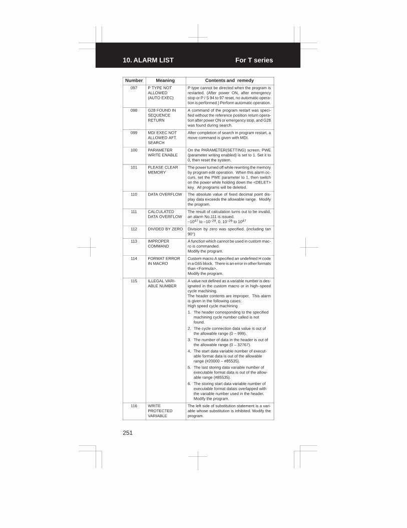
10. ALARM LIST For T series
251
Number Contents and remedyMeaning
097 P TYPE NOT ALLOWED (AUTO EXEC)
P type cannot be directed when the program isrestarted. (After power ON, after emergencystop or P / S 94 to 97 reset, no automatic opera-tion is performed.) Perform automatic operation.
098 G28 FOUND INSEQUENCE RETURN
A command of the program restart was speci-fied without the reference position return opera-tion after power ON or emergency stop, and G28was found during search.
099 MDI EXEC NOTALLOWED AFT.SEARCH
After completion of search in program restart, amove command is given with MDI.
100 PARAMETERWRITE ENABLE
On the PARAMETER(SETTING) screen, PWE(parameter writing enabled) is set to 1. Set it to0, then reset the system.
101 PLEASE CLEARMEMORY
The power turned off while rewriting the memoryby program edit operation. When this alarm oc-curs, set the PWE parameter to 1, then switchon the power while holding down the <DELET>key. All programs will be deleted.
110 DATA OVERFLOW The absolute value of fixed decimal point dis-play data exceeds the allowable range. Modifythe program.
111 CALCULATEDDATA OVERFLOW
The result of calculation turns out to be invalid,an alarm No.111 is issued.–1047 to –10–29, 0, 10–29 to 1047
112 DIVIDED BY ZERO Division by zero was specified. (including tan90°)
113 IMPROPER COMMAND
A function which cannot be used in custom mac-ro is commanded.Modify the program.
114 FORMAT ERRORIN MACRO
Custom macro A specified an undefined H codein a G65 block. There is an error in other formatsthan <Formula>.Modify the program.
115 ILLEGAL VARI-ABLE NUMBER
A value not defined as a variable number is des-ignated in the custom macro or in high–speedcycle machining.The header contents are improper. This alarmis given in the following cases:High speed cycle machining
1. The header corresponding to the specifiedmachining cycle number called is notfound.
2. The cycle connection data value is out ofthe allowable range (0 – 999).
3. The number of data in the header is out ofthe allowable range (0 – 32767).
4. The start data variable number of execut-able format data is out of the allowablerange (#20000 – #85535).
5. The last storing data variable number ofexecutable format data is out of the allow-able range (#85535).
6. The storing start data variable number ofexecutable format datais overlapped withthe variable number used in the header.Modify the program.
116 WRITE PROTECTEDVARIABLE
The left side of substitution statement is a vari-able whose substitution is inhibited. Modify theprogram.

3
1
4
5
6
7
8
9
10
2
252
Number Contents and remedyMeaning
118 PARENTHESISNESTING ERROR
The nesting of bracket exceeds the upper limit(quintuple).Modify the program.
119 ILLEGAL ARGUMENT
The SQRT argument is negative. Or BCD argu-ment is negative, and other values than 0 to 9are present on each line of BIN argument.Modify the program.
122 DUPLICATE MAC-RO MODAL–CALL
The macro modal call is specified in double.Modify the program.
123 CAN NOT USEMACRO COM-MAND IN DNC
Macro control command is used during DNC op-eration.Modify the program.
124 MISSING ENDSTATEMENT
DO – END does not correspond to 1 : 1. Modifythe program.
125 FORMAT ERRORIN MACRO
Custom macro A specified an undefined H codein a G65 block. <Formula> format is erroneous. Modify the pro-gram.
126 ILLEGAL LOOPNUMBER
In DOn, 1� n � 3 is not established. Modifythe program.
127 NC, MACROSTATEMENT INSAME BLOCK
NC and custom macro commands coexist.Modify the program.
128 ILLEGAL MACROSEQUENCE NUMBER
The sequence number specified in the branchcommand was not 0 to 9999. Or, it cannot besearched. Modify the program.
129 ILLEGAL ARGUMENT ADDRESS
An address which is not allowed in <ArgumentDesignation > is used.Modify the program.
130 ILLEGAL AXIS OPERATION
An axis control command was given by PMC toan axis controlled by CNC. Or an axis controlcommand was given by CNC to an axis con-trolled by PMC. Modify the program.
131 TOO MANY EXTERNALALARM MESSAGES
Five or more alarms have generated in externalalarm message.Consult the PMC ladder diagram to find thecause.
132 ALARM NUMBERNOT FOUND
No alarm No. concerned exists in external alarmmessage clear.Check the PMC ladder diagram.
133 ILLEGAL DATA INEXT. ALARM MSG
Small section data is erroneous in externalalarm message or external operator message.Check the PMC ladder diagram.
135 ILLEGAL ANGLECOMMAND
The index table indexing positioning angle wasinstructed in other than an integral multiple ofthe value of the minimum angle.Modify the program.
136 ILLEGAL AXISCOMMAND
In index table indexing.Another control axis wasinstructed together with the B axis.Modify the program.
139 CAN NOTCHANGE PMCCONTROL AXIS
An axis is selected in commanding by PMC axiscontrol.Modify the program.
141 CAN NOT COMMAND G51 INCRC
G51 (Scaling ON) is commanded in the tool off-set mode.Modify the program.
142 ILLEGAL SCALERATE
Scaling magnification is commanded in otherthan 1 – 999999.Correct the scaling magnification setting .

10. ALARM LIST For T series
253
Number Contents and remedyMeaning
143 SCALED MOTIONDATA OVERFLOW
The scaling results, move distance, coordinatevalue and circular radius exceed the maximumcommand value. Correct the program or scalingmangification.
144 ILLEGAL PLANESELECTED
The coordinate rotation plane and arc or cuttercompensation C plane must be the same.Modify the program.
148 ILLEGAL SETTINGDATA
Automatic corner override deceleration rate isout of the settable range of judgement angle.Modify the parameters (No.1710 to No.1714)
150 ILLEGAL TOOLGROUP NUMBER
Tool Group No. exceeds the maximum allow-able value in the tool life management.Modify the program.
151 TOOL GROUPNUMBER NOTFOUND
The tool group of the tool life management com-manded in the machining program is not set.Modify the value of program or parameter.
152 NO SPACE FORTOOL ENTRY
The number of tools within one group in the toollife management exceeds the maximum valueregisterable. Modify the number of tools.
153 T–CODE NOTFOUND
In tool life data registration, a T code was notspecified where one should be. Correct the pro-gram.
154 NOT USING TOOLIN LIFE GROUP
When the group is not commanded in the toollife management, H99 or D99 was commanded.Correct the program.
155 ILLEGAL T–CODEIN M06
In the machining program, M06 and T code inthe same block do not correspond to the tool lifemanagement group number in use. Correct theprogram.
156 P/L COMMANDNOT FOUND
P and L commands are missing at the head ofprogram in which the tool group of the tool lifemanagement is set. Correct the program.
157 TOO MANY TOOLGROUPS
The number of tool groups in the tool life man-agement to be set exceeds the maximum allow-able value. Modify the program.
158 ILLEGAL TOOLLIFE DATA
The tool life to be set is too excessive. Modifythe setting value.
159 TOOL DATA SET-TING INCOM-PLETE
During executing a life data setting program intool life management, power was turned off. Set again.
175 ILLEGAL G107COMMAND
Conditions when performing circular interpola-tion start or cancel not correct. To change themode to the cylindrical interpolation mode,specify the command in a format of “G07.1 rota-tion–axis name radius of cylinder.”
176 IMPROPER G–CODE IN G107
Any of the following G codes which cannot bespecified in the cylindrical interpolation modewas specified.
1) G codes for positioning: G28,, G73, G74,G76, G81 – G89, including the codesspecifying the rapid traverse cycle
2) G codes for setting a coordinate system:G52,G92,
3) G code for selecting coordinate system:G53 G54–G59
Modify the program.
177 CHECK SUM ERROR(G05 MODE)
Check sum error is occurred in the high–speedremote buffer.

3
1
4
5
6
7
8
9
10
2
254
Number Contents and remedyMeaning
178 G05 COMMAN-DED IN G41/G42MODE
G05 was commanded in the G41/G42 mode.Correct the program.
179 PARAMETER SETTING ERROR
The number of controlled axes set by the param-eter 7510 exceeds the maximum number.Modify the parameter setting value.
180 COMMUNICATIONERROR (REMOTE BUF)
Remote buffer connection alarm has generated.Confirm the number of cables, parameters andI/O device.
181 FORMAT ERRORIN G81 BLOCK
G81 block format error (hobbing machine)
1) T (number of teeth) has not beeninstructed.
2) Data outside the command range wasinstructed by either T, L, Q or P.
Modify the program.
182 G81 NOT COMMANDED
G83 (C axis servo lag quantity offset) wasinstructed though synchronization by G81 hasnot been instructed. Correct the program. (hob-bing machine)
183 DUPLICATE G83(COMMANDS)
G83 was instructed before canceled by G82 af-ter compensating for the C axis servo lag quanti-ty by G83. (hobbing machine)
184 ILLEGAL COMMAND IN G81
A command not to be instructed during synchro-nization by G81 was instructed. (hobbing ma-chine)
1) A C axis command by G00, G27, G28,G29, G30, etc. was instructed.
2) Inch/Metric switching by G20, G21 wasinstructed.
185 RETURN TO REFERENCEPOINT
G81 was instructed without performing refer-ence position return after power on or emergen-cy stop. (hobbing machine) Perform referenceposition return.
186 PARAMETER SETTING ERROR
Parameter error regarding G81 (hobbing ma-chine)
1) The C axis has not been set to be a rotaryaxis.
2) A hob axis and position coder gear ratiosetting error
190 ILLEGAL AXIS SELECT
In the constant surface speed control, the speci-fied axis command (P) contains an illegal value.Correct the program.
194 SPINDLE COMMAND INSYNCHRO–MODE
Cs contour control or rigid tapping was specifiedduring serial spindle synchronous control. Cor-rect the program.
195 SPINDLE CONTROL MODESWITCH
The serial spindle control mode was notswitched. Check the PMC ladder program.
197 C–AXIS COMMANDED INSPINDLE MODE
A command for Cs–axis movement was issuedwhen the current control mode is not serialspindle Cs contour control. Check the PMC lad-der program or machining program.
199 MACRO WORDUNDEFINED
Undefined macro word was used. Modify thecustom macro.
200 ILLEGAL S CODECOMMAND
In the rigid tap, an S value is out of the range oris not specified.Modify the program.

10. ALARM LIST For T series
255
Number Contents and remedyMeaning
201 FEEDRATE NOTFOUND IN RIGIDTAP
In the rigid tap, no F value is specified.Correct the program.
202 POSITION LSI OVERFLOW
In the rigid tap, spindle distribution value is toolarge.
203 PROGRAM MISSAT RIGID TAPPING
In the rigid tap, position for a rigid M code (M29)or an S command is incorrect. Modify the pro-gram.
204 ILLEGAL AXIS OPERATION
In the rigid tap, an axis movement is specifiedbetween the rigid M code (M29) block and G84(G74) block. Modify the program.
205 RIGID MODE DISIGNAL OFF
Rigid mode DI signal is not ON when G84 (G74)is executed though the rigid M code (M29) isspecified.Consult the PMC ladder diagram tofind the reason the DI signal (DGNG061.1) is notturned on. Modify the program.
206 CAN NOTCHANGE PLANE(RIGID TAP)
Plane changeover was instructed in the rigidmode.Correct the program.
210 CAN NOT COMAND M198/M199
M198 and M199 are executed in the scheduleoperation. M198 is executed in the DNC opera-tion.
211 CAN NOT COMMAND HIGH–SPEED SKIP
A high–speed skip (G31) was specified duringthe feed–per–rotation or rigid tapping mode.Correct the program.
212 ILLEGAL PLANESELECT
The arbitrary angle chamfering or a corner R iscommanded or the plane including an additionalaxis. Correct the program.
213 ILLEGAL COMMAND INSYNCHRO–MODE
Any of the following alarms occurred in the op-eration with the simple synchronization control.
1) The program issued the move command tothe slave axis.
2) The program issued the manual continu-ous feed/manual handle feed/incrementalfeed command to the slave axis.
3) The program issued the automatic refer-ence position return command withoutexecuting the manual reference positionreturn after the power was turned on.
4) The difference between the position erroramount of the master and slave axes ex-ceeded the value specified in parameter .
214 ILLEGAL COMMAND INSYNCHRO–MODE
Coordinate system is set or tool compensationof the shift type is executed in the synchronouscontrol. Correct the program.
222 DNC OP. NOT ALLOWED IN BG.–EDIT
Input and output are executed at a time in thebackground edition.Execute a correct operation.
224 RETURN TO REFERENCEPOINT
Reference position return has not been per-formed before the automatic operation starts.Perform reference position return.
230 R CODE NOTFOUND
The infeed quantity R has not been instructedfor the G160 block of th ecanned grinding cycle.Or the R command value is negative. Correctthe program.
250 SIMULTANEOUSM06 AND Z–AXISMOVEMENT NOTALLOWED
A tool change (M06) and a Z–axis movementwere specified simultaneously in the DRILLMATE. Correct the program.

3
1
4
5
6
7
8
9
10
2
256
(2) Background edit alarm
Number Meaning Contents and remedy
??? BACKGROUNDEDIT ALARM
BP/S alarm occurs in the same number as theP/S alarm that occurs in ordinary program edit.(070, 071, 072, 073, 074 085,086,087 etc.)
140 SELECTED PROGRAM ALARM
It was attempted to select or delete in the back-ground a program being selected in the fore-ground. (Note) Use background editing correctly.
NOTE A background editing alarm may occur even during MDI opera-
tion–B. This is because MDI operation–B uses the background
editing function.
(3) Absolute pulse coder (APC) alarm
Number Meaning Contents and remedy
3n0 nth–axis origin return
Manual reference position return is required forthe nth–axis.
3n1 APC alarm: nth–axis communication
nth–axis APC communication error. Failure indata transmission Possible causes include a faulty APC, cable, orservo interface module.
3n2 APC alarm: nth–axis over time
nth–axis APC overtime error. Failure in datatransmission.Possible causes include a faulty APC, cable, orservo interface module.
3n3 APC alarm: nth–axis framing
nth–axis APC framing error. Failure in datatransmission.Possible causes include a faulty APC, cable, orservo interface module.
3n4 APC alarm: nth–axis parity
nth–axis APC parity error. Failure in data trans-mission.Possible causes include a faulty APC, cable, orservo interface module.
3n5 APC alarm: nth–axis pulse error
nth–axis APC pulse error alarm. APC alarm.APC or cable may be faulty.
3n6 APC alarm: nth–axis batteryvoltage 0
nth–axis APC battery voltage has decreased toa low level so that the data cannot be held. APC alarm. Battery or cable may be faulty.
3n7 APC alarm: nth–axis battery low1
nth–axis axis APC battery voltage reaches alevel where the battery must be renewed.APC alarm. Replace the battery.
3n8 APC alarm: nth–axis battery low2
nth–axis APC battery voltage has reached alevel where the battery must be renewed (in-cluding when power is OFF).APC alarm.
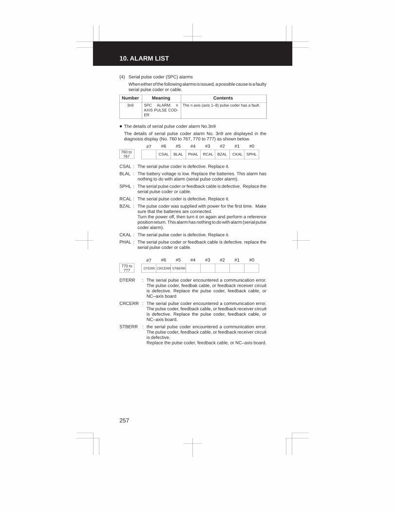
10. ALARM LIST
257
(4) Serial pulse coder (SPC) alarms
When either of the following alarms is issued, a possible cause is a faultyserial pulse coder or cable.
Number Meaning Contents
3n9 SPC ALARM: nAXIS PULSE COD-ER
The n axis (axis 1–8) pulse coder has a fault.
� The details of serial pulse coder alarm No.3n9
The details of serial pulse coder alarm No. 3n9 are displayed in thediagnosis display (No. 760 to 767, 770 to 777) as shown below.
#7 #6 #5 #4 #3 #2 #1 #0760 to
767 CSAL BLAL PHAL RCAL BZAL CKAL SPHL
CSAL : The serial pulse coder is defective. Replace it.
BLAL : The battery voltage is low. Replace the batteries. This alarm hasnothing to do with alarm (serial pulse coder alarm).
SPHL : The serial pulse coder or feedback cable is defective. Replace theserial pulse coder or cable.
RCAL : The serial pulse coder is defective. Replace it.
BZAL : The pulse coder was supplied with power for the first time. Makesure that the batteries are connected. Turn the power off, then turn it on again and perform a referenceposition return. This alarm has nothing to do with alarm (serial pulsecoder alarm).
CKAL : The serial pulse coder is defective. Replace it.
PHAL : The serial pulse coder or feedback cable is defective. replace theserial pulse coder or cable.
#7 #6 #5 #4 #3 #2 #1 #0770 to
777 DTERR CRCERR STBERR
DTERR : The serial pulse coder encountered a communication error.The pulse coder, feedbak cable, or feedback receiver circuitis defective. Replace the pulse coder, feedback cable, orNC–axis board
CRCERR : The serial pulse coder encountered a communication error.The pulse coder, feedback cable, or feedback receiver circuitis defective. Replace the pulse coder, feedback cable, orNC–axis board.
STBERR : the serial pulse coder encountered a communication error.The pulse coder, feedback cable, or feedback receiver circuitis defective.Replace the pulse coder, feedback cable, or NC–axis board.

3
1
4
5
6
7
8
9
10
2
258
(5) Servo alarms
Number Meaning Contents and actions
400 SERVO ALARM: 1,2TH AXIS OVER-LOAD
1–axis, 2–axis overload signal is on. Refer todiagnosis display No. 720 or 721 for details.
401 SERVO ALARM: 1,2TH AXIS VRDYOFF
1–axis, 2–axis servo amplifier READY signal(DRDY) went off.
402 SERVO ALARM: 3,4TH AXIS OVER-LOAD
3–axis, 4–axis overload signal is on. Refer todiagnosis display No. 722 or 723 for details.
403 SERVO ALARM: 3,4TH AXIS VRDYOFF
3–axis, 4–axis servo amplifier READY signal(DRDY) went off.
404 SERVO ALARM: n–TH AXIS VRDY ON
Even though the n–th axis (axis 1–8) READYsignal (MCON) went off, the servo amplifierREADY signal (DRDY) is still on. Or, when thepower was turned on, DRDY went on eventhough MCON was off.Check that the axis card and servo amplifierr areconnected.
405 SERVO ALARM:ZERO POINT RETURN FAULT
Position control system fault. Due to an NC orservo system fault in the reference position re-turn, there is the possibility that reference posi-tion return could not be executed correctly. Tryagain from the manual reference position return.
406 SERVO ALARM: 7, 8TH AXIS OVERLOAD7, 8TH AXIS VRDYOFF
7–axis, 8–axis overload signal is on. Refer todiagnosis display No. 726 or 727 for details.3–axis, 4–axis servo amplifier READY signal(DRDY) went off.
4n0 SERVO ALARM: n–TH AXIS – EXCESSERROR
The position deviation value when the n–th axisstops is larger than the set value.Note) Limit value must be set to parameter foreach axis.
4n1 SERVO ALARM: n–TH AXIS – EXCESSERROR
The position deviation value when the n–th axismoves is larger than the set value.Note) Limit value must be set to parameter foreach axis.
4n3 SERVO ALARM:n–th AXIS – LSIOVERFLOW
The contents of the error register for the n–thaxis exceeded ±231 power. This error usuallyoccurs as the result of an improperly set param-eters.
4n4 SERVO ALARM: n–TH AXIS – DETEC-TION RELATEDERROR
N–th axis digital servo system fault. Refer todiagnosis display No. 720 and No.727 for de-tails.
4n5 SERVO ALARM: n–TH AXIS – EXCESSSHIFT
A speed higher than 4000000 units/s was at-tempted to be set in the n–th axis. This error oc-curs as the result of improperly set CMR.
4n6 SERVO ALARM: n–TH AXIS – DIS-CONNECTION
Position detection system fault in the n–th axispulse coder (disconnection alarm).

10. ALARM LIST
259
Number Contents and actionsMeaning
4n7 SERVO ALARM: n–TH AXIS – PA-RAMETER INCOR-RECT
This alarm occurs when the n–th axis is in oneof the conditions listed below. (Digital servosystem alarm)
1) The value set in Parameter No. 8n20 (mo-tor form) is out of the specified limit.
2) A proper value (111 or –111) is not set inparameter No. 8n22 (motor revolutiondirection).
3) Illegal data (a value below 0, etc.) was setin parameter No. 8n23 (number of speedfeedback pulses per motor revolution).
4) Illegal data (a value below 0, etc.) was setin parameter No. 8n24 (number of positionfeedback pulses per motor revolution).
5) Parameters No. 8n84 and No. 8n85 (flex-ible field gear rate) have not been set.
6) An axis selection parameter (from No. 269to 274) is incorrect.
7) An overflow occurred during parametercomputation.
490 SERVO ALARM:5TH AXIS OVERLOAD
5–axis, 6–axis overload signal is on. Refer todiagnosis display No. 724 or 725 for details.
491 SERVO ALARM: 5,6TH VRDY OFF
5–axis, 6–axis servo amplifier READY signal(DRDY) went off.
494 SERVO ALARM: 5,6TH AXIS VRDYON
The axis card ready signal (MCON) for axes 5and 6 is off, but the servo amplifier ready signal(DRDY) is not. Alternatively, when the power isapplied, the DRDY is on, but the MCON is not.Ensure that the axis card and servo amplifier areconnected.
495 SERVO ALARM: 5,6TH AXIS ZEROPOINT RETURN
This is a position control circuit error. It is likelythat a return to the reference position failed be-cause of an error in the NC or the servo system.Retry a return to the reference position.
NOTE If an excessive spindle error alarm occurs during rigid tapping, the
relevant alarm number for the tapping feed axis is displayed.

3
1
4
5
6
7
8
9
10
2
260
� Details of servo alarm No.4n4
The detailed descriptions of servo alarm number 414 are displayed withdiagnosis numbers 720 to 727 in the sequence of axis numbers.
#7 #6 #5 #4 #3 #2 #1 #0720 to
727 OVL LV OVC HCAL HVA DCAL FBAL OFAL
OVL : An overload alarm is being generated. (This bit causes servo alarm No. 400, 402, 406, 490).
LV : A low voltage alarm is being generated in servo amp. Check LED.
OVC : A overcurrent alarm is being generated inside of digital servo.
HCAL : An abnormal current alarm is being generated in servo amp.Check LED.
HVAL : An overvoltage alarm is being generated in servo amp. Check LED.
DCAL : A regenerative discharge circuit alarm is being generated in servoamp.Check LED.
FBAL : A disconnection alarm is being generated.(This bit causes servo alarm No.4n6.)
OFAL : An overflow alarm is being generated inside of digital servo.
(6) Spindle alarms
Number Meaning Contents and remedy
408 SPINDLE SERIALLINK START FAULT
This alarm is generated when the spindle con-trol unit is not ready for starting correctly whenthe power is turned on in the system with the se-rial spindle.The four reasons can be considered as follows:
1) An improperly connected optic cable, orthe spindle control unit’s power is OFF.
2) When the NC power was turned on underalarm conditions other than SU–01 orAL–24 which are shown on the LED dis-play of the spindle control unit.In this case, turn the spindle amplifier pow-er off once and perform startup again.
3) Other reasons (improper combination ofhardware)This alarm does not occur after the systemincluding the spindle control unit is acti-vated.
409 SPINDLE ALARMDETECTION
A spindle amplifier alarm occurred in a systemwith a serial spindle. The alarm is indicated as”AL–XX” (where XX is a number) on the displayof the spindle amplifier. For details, see Section14. Setting bit 7 of parameter No. 0397 causesthe spindle amplifier alarm number to appear onthe screen.

10. ALARM LIST
261
(7) Over travel alarms
Number Meaning Contents and remedy
5n0 OVER TRAVEL : +n Exceeded the n–th axis + side stored stroke lim-it 1, 2.
5n1 OVER TRAVEL : –n Exceeded the n–th axis – side stored stroke lim-it 1, 2.
5n2 OVER TRAVEL : +n Exceeded the n–th axis + side stored stroke lim-it 3.
5n3 OVER TRAVEL : –n Exceeded the n–th axis – side stored stroke lim-it 3.
5n4 OVER TRAVEL : +n Exceeded the n–th axis + side hardware OT. (for M series)
5n5 OVER TRAVEL : –n Exceeded the n–th axis – side hardware OT.(for M series)
5n4 OVERTRAVEL AT+N AXIS
The tool moved beyond stored stroke limit 4 inthe positive direction of the n axis (for T series).
5n5 OVERTRAVEL AT –N AXIS
The tool moved beyond stored stroke limit 4 inthe negative direction of the n axis (for T series).
520 OVERTRAVEL AT –Z–AXIS
The tool moved beyond the hardware overtravelposition in the positive direction of the Z–axis(for T series).
590 TOOL–POST IN-TERFERENCEALARM AT +X–AXIS
A tool–post interference alarm was issued whilethe tool was moving in the positive directionalong the X–axis.
591 TOOL–POST IN-TERFERENCEALARM AT –X–AXIS
A tool–post interference alarm was issued whilethe tool was moving in the negative directionalong the X–axis.
592 TOOL–POST IN-TERFERENCEALARM AT +Z–AXIS
A tool–post interference alarm was issued whilethe tool was moving in the positive directionalong the Z–axis.
593 TOOL–POST IN-TERFERENCEALARM AT –Z–AXIS
A tool–post interference alarm was issued whilethe tool was moving in the negative directionalong the Z–axis.
(8) Macro alarms
Number Meaning Contents and remedy
500 to599
MACRO ALARM This alarm is related to the custom macro, mac-ro executor, or order–made macro (includingconversational program inputs). Refer to therelevant manual for details. (The macro alarmnumber may coincide with an overtravel alarmnumber. However, they can be distinguishedfrom each other because the overtravel alarmnumber is accompanied with the description ofthe alarm.

3
1
4
5
6
7
8
9
10
2
262
(9) PMC alarms
Number Meaning Contents and remedy
600 PMC ALARM : IN-VALID INSTRUC-TION
An invalid–instruction interrupt occurred in thePMC.
601 PMC ALARM : RAMPARITY
A PMC RAM parity error occurred.
602 PMC ALARM : SE-RIAL TRANSFER
A PMC serial transfer error occurred.
603 PMC ALARM :WATCHDOG
A PMC watchdog timer alarm occurred.
604 PMC ALARM : ROMPARITY
A PMC ROM parity error occurred.
605 PMC ALARM :OVER STEP
The maximum allowable number of PMC ladderprogram steps was exceeded.
606 PMC ALARM : I/OMODULE ASSIGN-MENT
The assignment of I/O module signals is incor-rect.
607 PMC ALARM : I/OLINK
An I/O link error occurred. The details are listedbelow.
Number Details of PMC alarm (No. 607)
010 * Communication error (SLC (master) internal register error)
020 * An SLC RAM bit error occurred (verification error).
030 * An SLC RAM bit error occurred (verification error).
040 No I/O unit has been connected.
050 32 or more I/O units are connected.
060 * Data transmission error (no response from the slave)
070 * Communication error (no response from the slave)
080 * Communication error (no response from the slave)
090 An NMI (for other than alarm codes 110 to 160) occurred.
130 * An SLC (master) RAM parity error occurred (detected by hard-ware).
140 * An SLC (slave) RAM parity error occurred (detected by hard-ware).
160 * SLC (slave) communication error* AL0 : Watchdog timer
DO clear signal received* IR1 : CRC or framing error
Watchdog timer alarmParity error
Hardware errors are indicated with an asterisk (*).
(10) Overheat alarms
Number Meaning Contents and remedy
700 OVERHEAT: CON-TROL UNIT
Control unit overheatCheck that the fan motor operates normally, andclean the air filter.
704 SPINDLE OVER-HEAT
Spindle overheat was detected by the spindle–speed fluctuation detection function (for T se-ries).Check the machining conditions.

10. ALARM LIST
263
(11) M–NET alarm
Number Meaning Contents and remedy
899 M–NET INTER-FACE ALARM
This alarm is related to a serial interface for anexternal PLC. The details are listed below.
Number Details of M–NET alarm (No. 899)
0001 Abnormal character (character other than transmission codes) re-ceived
0002 ”EXT” code error
0003 Connection time monitor error (parameter No. 0464)
0004 Polling time monitor error (parameter No. 0465)
0005 Vertical parity or framing error detected
0257 Transmission time–out error (parameter No. 0466)
0258 ROM parity error
0259 Overrun error detected
Others CPU interrupt detected
(12) System alarms
(These alarms cannot be reset with reset key.)
Number Meaning Contents and remedy
910 MAIN RAM PARITY
This RAM parity error is related to low–order by-tes. Replace the memory PC board.
911 MAIN RAM PARITY
This RAM parity error is related to high–orderbytes. Replace the memory PC board.
912 SHARED RAMPARITY
This parity error is related to low–order bytes ofRAM shared with the digital servo circuit. Re-place the axis control PC board.
913 SHARED RAMPARITY
This parity error is related to high–order bytes ofRAM shared with the digital servo circuit. Re-place the axis control PC board.
914 SERVO RAM PARITY
This is a local RAM parity error in the digital ser-vo circuit. Replace the axis control PC board.
915 LADDER EDITINGCASSETTE RAMPARITY
This RAM parity error is related to low–order by-tes of the ladder editing cassette. Replace theladder editing cassette.
916 LADDER EDITINGCASSETTE RAMPARITY
This RAM parity error is related to high–orderbytes of the ladder editing cassette. Replacethe ladder editing cassette.
920 WATCHDOGALARM
This is a watchdog timer alarm or a servo sys-tem alarm for axis 1 to 4. Replace the master oraxis control PC board.
921 SUB CPU WATCH-DOG ALARM
This is a watchdog timer alarm related to thesub–CPU board or a servo system alarm foraxis 5 or 6. Replace the sub–CPU board or theaxis–5/6 control PC board.
922 7/8 AXIS SERVOSYSTEM ALARM
This is a servo system alarm related to axis 7 or8. Replace the axis–7/8 control PC board.
930 CPU ERROR This is a CPU error. Replace the master PCboard.
940 PC BOARDINSTALLATIONERROR
PC board installation is incorrect. Check thespecification of the PC board.
941 MEMORY PCBOARD CONNEC-TION ERROR
The memory PC board is not connected secure-ly. Ensure that the PC board is connected se-curely.

3
1
4
5
6
7
8
9
10
2
264
Number Contents and remedyMeaning
945 SERIAL SPINDLECOMMUNICATIONERROR
The hardware configuration is incorrect for theserial spindle, or a communication alarm oc-curred. Check the hardware configuration of thespindle. Also ensure that the hardware for theserial spindle is connected securely.
946 SECOND SERIALSPINDLE COMMU-NICATION ERROR
Communication is impossible with the secondserial spindle. Ensure that the second serialspindle is connected securely.
950 FUSE BLOWNALARM
A fuse has blown. Replace the fuse (+24E;F14).
960 SUB CPU ERROR This is a sub–CPU error. Replace the sub–CPUPC board.
998 ROM PARITY This is a ROM parity error. Replace the ROMboard in which the error occurred.
(13) External alarm
Number Meaning Contents and remedy
1000 EXTERNALALARM
This alarm was detected by the PMC ladder pro-gram. Refer to the relevant manual from the ma-chine builder for details.
(14) Alarms Displayed on spindle Servo Unit
AlarmNo.
Meaning Description Remedy
“A”display
Program ROM ab-normality (notinstalled)
Detects that control programis not started (due to programROM not installed, etc.)
Install normalprogram ROM
AL–01 Motoroverheat
Detects motor speed exceed-ing specified speed exces-sively.
Check loadstatus.Cool motorthen resetalarm.
AL–02 Excessive speeddeviation
Detects motor speed exceed-ing specified speed exces-sively.
Check loadstatus.Reset alarm.
AL–03 DC link section fuseblown
Detects that fuse F4 in DC linksection is blown (models 30Sand 40S).
Check powertransistors,and so forth.Replace fuse.
AL–04 Input fuse blown.Input power openphase.
Detects blown fuse (F1 to F3),open phase or momentaryfailure of power (models 30Sand 40S).
Replace fuse.Check openphase andpower supplyrefenerativecircuit opera-tion.
AL–05 Control power sup-ply fuse blown
Detects that control powersupply fuse AF2 or AF3 isblown (models 30S and 40S).
Check for con-trol power sup-ply short circuit.Replace fuse.
AL–07 Excessive speed Detects that motor rotationhas exceeded 115% of itsrated speed.
Reset alarm.
AL–08 High input voltage Detects that switch is flippedto 200 VAC when input volt-age is 230 VAC or higher(models 30S and 40S).
Flip switch to230 VAC.

10. ALARM LIST
265
AlarmNo. RemedyDescriptionMeaning
AL–09 Excessive load onmain circuit section
Detects abnormal tempera-ture rise of power transistor ra-diator.
Cool radiatorthen resetalarm.
AL–10 Low input voltage Detects drop in input powersupply voltage.
Removecause, then re-set alarm.
AL–11 Overvoltage in DClink section
Detects abnormally high di-rect current power supply volt-age in power circuit section.
Removecause, then re-set alarm.
AL–12 Overcurrent in DClink section
Detects flow of abnormallylarge current in direct currentsection of power cirtcuit
Removecause, then re-set alarm.
AL–13 CPU internal datamemory abnormal-ity
Detects abnormality in CPUinternal data memory. Thischeck is made only whenpower is turned on.
Removecause, then re-set alarm.
AL–15 Spindle switch/out-put switch alarm
Detects incorrect switch se-quence in spindle switch/out-put switch operation.
Check se-quence.
AL–16 RAM abnormality Detects abnormality in RAMfor external data. This checkis made only when power isturned on.
Removecause, then re-set alarm.
AL–18 Program ROM sumcheck error
Detects program ROM dataerror.This check is made onlywhen power is turned on.
Removecause, then re-set alarm.
AL–19 Excessive U phasecurrent detectioncircuit offset
Detects excessive U phasecurrent detection ciucuit off-set.This check is made only whenpower is turned on.
Removecause, then re-set alarm.
AL–20 Excessive V phasecurrent detectioncircuit offset
Detects excessive V phasecurrent detection circuit off-set.This check is made only whenpower is turned on.
Removecause, then re-set alarm.
AL–24 Serial transfer dataerror
Detects serial transfer data er-ror (such as NC power supplyturned off, etc.)
Removecause, then re-set alarm.
AL–25 Serial data transferstopped
Detects that serial data trans-fer has stopped.
Removecause, then re-set alarm.
AL–26 Disconnection ofspeed detectionsignal for Cs con-touring control
Detects abnormality in posi-tion coder signal(such as un-connected cable and parame-ter setting error).
Removecause, then re-set alarm.
AL–27 Position coder sig-nal disconnection
Detects abnormality in posi-tion coder signal (such as un-connected cable and adjust-ment error).
Removecause, then re-set alarm.
AL–28 Disconnection ofposition detectionsignal for Cs con-touring control
Detects abnormality in posi-tion detection signal for Cscontouring control (such asunconnected cable and ad-justment error).
Removecause, then re-set alarm.
AL–29 Short–time over-load
Detects that overload hasbeen continuously applied forsome period of time (such asrestraining motor shaft in posi-tioning).
Removecause, then re-set alarm.

3
1
4
5
6
7
8
9
10
2
266
AlarmNo. RemedyDescriptionMeaning
AL–30 Input circuit over-current
Detects overcurrent flowing ininput circuit.
Removecause, then re-set alarm.
AL–31 Speed detectionsignal disconnec-tion motor restraintalarm or motor isclamped.
Detects that motor cannot ro-tate at specified speed or it isdetected that the motor isclamped. (but rotates at veryslow speed or has stopped).(This includes checking ofspeed detection signal cable.)
Removecause, then re-set alarm.
AL–32 Abnormality in RAMinternal to LSI forserial data transfer.This check is madeonly when power isturned on.
Detects abnormality in RAMinternalto LSI for serial datatransfer. This check is madeonly when power is turned on.
Removecause, then re-set alarm.
AL–33 Insufficient DC linksection charging
Detects insuffieient chargingof direct current power supplyvoltage in power circuit sec-tion when magnetic contactorin amplifier is turned on (suchas open phase and defectifvecharging resistor).
Removecause, then re-set alarm.
AL–34 Parameter data set-ting beyond allow-able range of values
Detects parameter data setbeyond allowable range ofvalues.
Set correctdata.
AL–35 Excesive gear ratiodata setting
Detects gear ratio data set be-yond allowable range of val-ues.
Set correctdata.
AL–36 Error counter overflow
Detects error counter over-flow.
Correct cause,then resetalarm.
AL–37 Speed detector pa-rameter setting er-ror
Detects incorrect setting ofparameter for number ofspeed detection pulses.
Set correctdata.
AL–39 Alarm for indicatingfailure in detecting1–rotation signal forCs contouring con-trol
Detects 1–rotaion signaldetection failure in Cs con-touring contorl.
Make 1–ro-taion signaladjustment.Check cableshield status.
AL–40 Alarm for indicating1–rotation signal forCs contouring con-trol not detected
Detects that 1–rotation signalhas not occurred in Cs con-touring control.
Make 1–ro-taion signaladjustment.
AL–41 Alarm for indicatingfailure in detectingposition coder 1–ro-taion signal.
Detects failure in detectingposition coder 1–rotation sig-nal.
Make signaladjustment forsignal conver-sion circuit.Check cableshield status.
AL–42 Alarm for indicatingposition coder1–rotation signalnot detected
Detects that position coder1–rotation signal has not is-sued.
Make 1–rota-tion signal ad-justment forsignal conver-sion circuit.

10. ALARM LIST
267
AlarmNo. RemedyDescriptionMeaning
AL–43 Alarm for indicatingdisconnection ofposition coder sig-nal for differentialspeed mode
Detects that main spindleposition coder signal used fordifferential speed mode is notconnected yet (or is discon-nected).
Check thatmain spindleposition codersignal is con-nected to con-nector CN12.
AL–46 Alarm for indicatingfailure in detectingposition coder1–rotation signal inthread cutting op-eration.
Detects failure in detectingposition coder 1–rotation sig-nasl in thread cutting opera-tion.
Make 1–rota-tion signal ad-justment forsignal conver-sion circuitCheck cableshield status.
AL–47 Position coder sig-nal abnormality
Detects incorrect positioncoder signal count operation.
Make signaladjustment forsignal conver-sion circuit.Check cableshield status.
AL–48 Position coder1–rotation signalabnormailty
Detects that occurrence ofposition coder 1–rotation sig-nal has stopped.
Make 1–rota-tion signal ad-justment forsignal conver-sion circuit.
AL–49 The converted dif-ferential speed istoo high.
Detects that speed of otherspindle converted to speed oflocal spindle has exceededallowable limit in differentialmode.
Check theposition coderstate of theother side.
AL–50 Excessive speedcommand calcula-tion value in spindlesynchronizationcontrol
Detects that speed commandcalculation value exceededallowable range in spindlesynchronization control.
Check param-eters such as aposition gain.
AL–51 Undervoltage at DClink section
Detects that DC power supplyvoltage of power ciucuit hasdropped (due to momentarypower failure or loose contactof magnetic contactor).
Removecause, then re-set alarm.
AL–52 ITP signal abnormality I
Detects abnormality in syn-chronization signal (ITP sig-nal )with CNC (such as loss ofITP signal).
Removecause, then re-set alarm.
AL–53 ITP signal abnormality II
Detects abnormality in syn-chronization signal (ITP sig-nal) with CNC (such as loss ofITP signal).
Removecause, then re-set alarm.
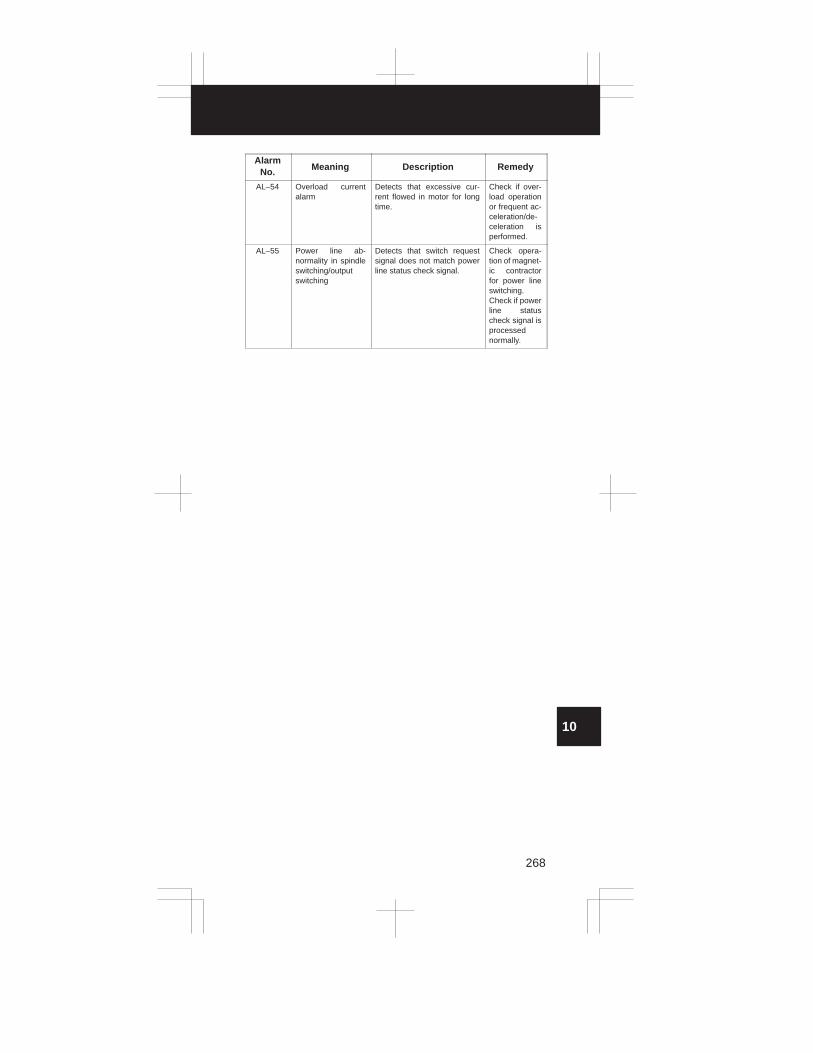
3
1
4
5
6
7
8
9
10
2
268
AlarmNo. RemedyDescriptionMeaning
AL–54 Overload currentalarm
Detects that excessive cur-rent flowed in motor for longtime.
Check if over-load operationor frequent ac-celeration/de-celeration isperformed.
AL–55 Power line ab-normality in spindleswitching/outputswitching
Detects that switch requestsignal does not match powerline status check signal.
Check opera-tion of magnet-ic contractorfor power lineswitching.Check if powerline statuscheck signal isprocessednormally.

3
1
4
5
6
7
8
9
10
2
11
11. CORRESPONDENCE BETWEEN ENGLISH KEY AND SYMBOLIC KEY
269
Table : Correspondence between English key and Symbolic key
Name English key Symbolic key
RESET key RESET
PAGE UP keyPAGE
PAGE DOWN key PAGE
SHIFT key SHIFT
POSITION key POS
PROGRAM key PRGRM
MENU key MENU
OFFSET key OFSET
MENU/OFFSET key MENUOFSET
DIAGNOS/PARAM key DGNOS
PARAM
OPRATION/ALARM key OPRALARM
AUXILIARY/GRAPHICkey
AUX
GRAPH
MACRO key MACRO
ALTER key ALTER
INSERT key INSRT
INPUT key INPUT
OUTPUT/START key OUTPT
START
DELETE key DELET
CANCEL key CAN
Top Related