


Languages
Pages
Legal


Gas Fired Double-Effect Chiller-HeaterCH-MG Series: 150 and 200 RT Cooling Capacities
W E A R E F R I E N D L Y T O T H E E A R T H

Yazaki MG-Series gas fired DOUBLE-EFFECT chiller-heaters, with cooling capacities of 150 and 200 tons of refrigeration, are designed for commercial applications where chilled water and hot water are used in a central air conditioning system. The condenser is water cooled and heat is rejected through a cooling tower.
The Yazaki absorption chiller-heater uses a solution of lithium bromide and water, under a vacuum, as the working fluid. Water is the refrigerant and lithium bromide, a nontoxic salt, is the absorbent. The double-effect absorption cycle has two generators - one directly heated by a gas burner and the other heated by hot refrigerant vapor. Refrigerant, liberated by heat from the solution, produces a refrigerating effect in the evaporator when cooling water is circulated through the condenser and absorber.
Gas FiredDOUBLE-EFFECTChiller-Heater
Absorption Principle
Cooling Cycle
High-Temperature GeneratorThe gas burner heats dilute lithium bromide solution in the high-temperature generator and, as the solution boils vigorously under a vacuum, droplets of concentrated solution are carried with refrigerant vapor to the separator. After separation, hot refrigerant vapor flows to the low-temperature generator and concentrated solution is precooled in the heat exchanger before flowing to the absorber.
Low-Temperature GeneratorHot refrigerant vapor from the separator heats dilute lithium bromide solution in the low-temperature generator. Refrigerant vapor, liberated from this solution, flows to the condenser while solution, which is now concentrated, is precooled in the heat exchanger before flowing to the absorber.
CondenserIn the condenser, refrigerant vapor is condensed on the surface of the coil and latent heat, removed by the cooling water, is rejected to a cooling tower. Refrigerant liquid accumulates in the condenser and then passes through an orifice into the evaporator.
HEAT EXCHANGER
SOLUTION PUMP
CHANGEOVER VALVE(Solution)
CH-MG (COOLING)
Gas Supply
HIGH TEMPGENERATOR
LOW TEMPGENERATOR
SEPARATOR
CHANGEOVER VALVE(Refrigerant)
ABSORBER
EVAPORATOR
CONDENSER
ORIFICE
Refrigerant Vapor
Chilled Water
Cooling Water
BURNER
EVAPORATOR
ORIFICE
Chilled Water
ConcentratedSolution
DiluteSolution
RefrigerantLiquid
RefrigerantVapor
ChilledWater
Cooling Water
2

EvaporatorIn the evaporator, refrigerant liquid is exposed to a substantially deeper vacuum than in the condenser due to the influence of the absorber. As refrigerant liquid flows over the surface of the evaporator coil it boils and removes heat, equivalent to the latent heat of the refrigerant, from the chilled water circuit. The recirculating chilled water is cooled to 44.6˚F and the refrigerant vapor is attracted to the absorber.
AbsorberA deep vacuum in the absorber is maintained by the affinity of the concentrated solution from the generator with the refrigerant vapor formed in the evaporator. Refrigerant vapor is absorbed by concentrated lithium bromide solution flowing across the surface of the absorber coil. Heat of condensation and dilution are removed by the cooling water and rejected to a cooling tower. The resulting dilute solution is preheated in the heat exchanger before returning to the generator where the cycle is repeated.
Heating Cycle
High-Temperature GeneratorDilute lithium bromide solution is heated in the high-temperature generator by the gas burner in the same manner as the cooling cycle. The solution boils vigorously and droplets of concentrated solution are carried with refrigerant vapor to the separator. Hot refrigerant vapor flows through the refrigerant changeover valve into the evaporator and concentrated solution flows through the solution changeover valve into the absorber sump.
EvaporatorHot refrigerant vapor condenses on the surface of the evaporator coil and heat, equivalent to the latent heat of the refrigerant, is transferred to the hot water circuit. The recirculating water is heated to 140˚F.
AbsorberRefrigerant liquid mixes with concentrated lithium bromide solution and the resulting dilute solution returns to the generator where the cycle is repeated.
HEAT EXCHANGER
SOLUTION PUMP
CHANGEOVER VALVE(Solution)
CH-MG (HEATING)
Gas Supply
HIGH TEMPGENERATOR
LOW TEMPGENERATOR
SEPARATOR
CHANGEOVER VALVE(Refrigerant)
ABSORBER
CONDENSER
ORIFICE
Hot Water
BURNER
RefrigerantLiquid
EVAPORATOR
ORIFICE
Hot Water
EVAPORATOR
ConcentratedSolution
DiluteSolution
HotWater
RefrigerantVapor
3
Features & Benefits n Each Chiller-Heater Serves a Dual Purpose: Cooling and Heating This compact chiller-heater reduces floor space and installation costs because it replaces the traditional chiller-boiler combination and simplifies piping, pumps, valves and controls.
n High Cooling COP of 1.2 Reduces fuel consumption and operating costs by up to 17% compared with other double-effect absorption units.
n Part Load IPLV Rating >1.3 Reduces seasonal fuel consumption because the chiller operates more efficiently at part load for most of the time.
n Low NOx Gas Burner <30 ppm Advanced Riello low NOx gas burners are used to meet the strict air quality requirements of California and other states.
n Hermetic Integrity Strict quality control and testing with a mass spectrometer ensures the vacuum section is airtight and eliminates the need for an onboard mechanical purge pump. Hydrogen, a by-product of the absorption cycle, is continuously removed through a palladium cell or stored with other noncondensible gases in an external purge tank
n PID Microprocessor PID (proportional, integral and differential) controls are utilized to optimize the absorption cycle performance and provide stable chilled water and hot water outlet temperatures under all load conditions.
n Burner Firing is Modulated 30% to 100% The burner is proportionally controlled to match the output capacity of the chiller- heater and reduce operating costs.
n Safe, Odorless, Non-toxic Working Fluids Ozone safe and CFC free. Working fluids of non-toxic lithium bromide and water operate safely under a vacuum at all times.
n A Single VFD Hermetic Solution Pump One variable speed pump circulates solution and reduces electrical consumption at part load. Additional pumps are not required because gravity feed drippers are used to distribute refrigerant and solution instead of spray nozzles. This eliminates the need for periodic nozzle maintenance.
n Low Cooling Water Temperature Cooling operation allowed down to 65˚F inlet cooling water without the need for cooling tower bypass control.
n Weatherproof Cabinet Equipment room is not required because the chiller-heater is enclosed in a weatherproof cabinet suitable for indoor or outdoor installation.
n Low Electrical Consumption Since less than 19.3 VA/RT is required to operate the chiller-heater, it is not neccessary to upgrade the existing electrical service.
4

Features & Benefits(Continued)
n Built-In Shutdown Controls Safely shuts down the chiller-heater under abnormal operating conditions.
n Ideal for a Two Pipe Hydronic System Installation costs reduced because only two pipes are required to transport chilled or hot water to a central air handling unit or multiple fan-coil units.
n 30 Minute Changeover Cooling/heating changeover only requires a 30 minute delay.
n Simple Mode Selection Cooling or heating operation can be selected at the chiller-heater or remotely from the building management system.
n Built-In Digital Display Panel Used for mode selection, operating status and troubleshooting.
n Remote Chilled Water and Hot Water Reset Raise chilled water setpoint or lower hot water setpoint to reduce operating costs during unoccupied hours.
n Hinged Marine Water Boxes Allow easy access to the condenser and absorber for tube cleaning and maintenance without disconnecting piping.
n Factory Installed Crossover Pipe and Insulation Eliminates site fabrication and installation of crossover pipe between the absorber and condenser and site insulation of cold and hot surfaces. n Simplified Transportation and Lifting Each modular chiller-heater is mounted on a steel frame and anchor points are provided for lifting.
n Quiet Operation Since the chiller-heater has relatively few moving parts, the noise level is typically less than 74idB(A) and there is no vibration. The chiller-heater is ideal for installation adjacent to occupied spaces because it does not compromise occupant comfort.
n Simple Maintenance Only two routine service calls are required per year to evacuate noncondensible gases and check other operating conditions. Start-up, routine maintenance and troubleshooting are provided by a network of independent Yazaki authorized service providers with backup from the factory.
n Factory Charged and Performance Tested Since each chiller-heater is shipped completely assembled and tested, installation and start-up are simplified.
n ISO9001 and ISO14001 Factory Certification Quality control is assured by compliance with strict manufacturing and industry standards.
n UL Listed for USA and Canada
5

Control Characteristics
6
Minimum Setpoint
Maximum Setpoint
Minimum Setpoint
105039.2
41.0
42.8
44.6
46.4
48.2
50.0
51.8
53.6
55.4
15 20 25
Time (min)
Standard Rating Point
Digital PID Control
COOLINGSETPOINT
Chi
lled
Wat
er O
utle
t Tem
p. (
˚F)
Minimum Setpoint
Maximum Setpoint Maximum Setpoint
1050
131.0
132.8
134.6
102.2
104.0
105.8
136.4
138.2
140.0
141.8
143.6
145.4
147.5
15 20 25
Time (min)
HEATINGSETPOINT
Hot
Wat
er O
utle
t Tem
p. (
˚F)
Minimum Setpoint
Maximum Setpoint
2010035.6
39.2
42.8
46.4
50.0
53.6
57.2
30 40 50 60
Time (min)
Chilled Water Inlet Temp.
Chilled Water Outlet Temp.
Proportional ControlDigital PID Control
PID COOLING CONTROL
Chi
lled
Wat
erTe
mp.
(˚F
)
8070
123.8
127.4
131.0
134.6
138.2
141.8
143.6
40 50 60
Time (min)
Hot Water Outlet Temp.
Hot Water Inlet Temp.
Hot
Wat
erTe
mp.
(˚F
)
8070Proportional ControlDigital PID Control
80%Load
50% Load 80%Load
20100 30
PID HEATING CONTROL
80%Load
50% Load 80%Load

Standard Specification
Application (Gas Fired Cooling & Heating System – Cooling Operation)
DiluteSolution
RefrigerantLiquid
RefrigerantVapor
ChilledWater
Cooling Water
ConcentratedSolution
GAS FIRED DOUBLE-EFFECT CHILLER-HEATER
FAN COIL UNIT
COOLAIR
COOLING TOWERGasSupply
* Minimum cooling water flow
7
NOTES:1. Fuel input is based on H I G H E R H E AT I N G VALUE of gas.2. Specifications are based on water in all circuits and foul ing fac tor of 0.0005 ft2hr.˚F/Btu.3. Do not exceed 114 psi operating pressure in any water circuit.4. Chilled/hot water flow limits are 80~120% of standard rating.5. Cooling water flow limits are 100~120% of standard rating. 6. Two or more modules m a y b e i n s t a l l e d i n p a r a l l e l f o r l a r g e r capacities.7. S t anda rd na tu r a l ga s supply pressure is 7.0 in. wc.8. Sound pressure noise level measured in a free field at a point 39 in. in front of the chiller-heater and 59 in. above the ground.
MODEL CH-MG150 CH-MG200
Capacity (Btu/hr x 1000)Chilled Water Temp. (°F)Capacity (Btu/hr x 1000) Hot Water Temp. (°F)
Heat Rejection (Btu/hr x 1000)Cooling Water Temp. (˚F)*Rated Water Flow (gpm)Cond./Abs. Press. Loss (psi) Water Retention Volume (gal) TypeInput (Btu/hr x 1000)Power SupplyConsumption (kVA)Cooling and HeatingTypeFlame DetectionIgnitionSound Pressure dB(A)
1,800 2,400
1,245 1,660
3,045 4,060
658.6 878.1
114 153
CoolingHeating
1,500 2,0001,500 2,000
CoolingHeating
2.9 3.32.9 3.3
74 74Chilled/Hot Water (in)Cooling Water (in)Gas Supply (in)Exhaust Vent (in)
4 Flange 5 Flange5 Flange 6 Flange2 NPT 2 NPT
12,346 14,330Dry (lb) Operating (lb) 13,698 16,183
Cooling
Heating
Cooling Water
Fuel
Electrical
Control
Combustion
Piping
Noise Level
Weight
13.8 x 9.8 (inside)
30% - 100% PID ControlLow NOx Forced Draft Burner
UV ScannerIntermittent Spark
208V or 230V, 60Hz, 3ph
Natural Gas
7.5
85.1 Inlet, 94.3 Outlet
140.0 Outlet, 132.8 Inlet
44.6 Outlet, 53.6 Inlet
Rated Water Flow (gpm)Evap. Press. Loss (psi)Water Retention Volume (gal)
399.4 532.6
48 69
Chilled/HotWater 10.5 9.2
7.2
TypeMaterialFinish
Weatherproof
Silver metallicCabinet Pre-painted hot dipped galvanized steel

NOTES:1. Capacities are based on standard gas input ratings.2. Standard water flow rates used in all circuits.3. Fouling factor of 0.0005 ft2hr.˚F/Btu in the condenser/absorber and evaporator.4. Performance data may be interpolated but must not be extrapolated.5. Expanded performance data is provided for reference only. Contact Yazaki Energy Systems, Inc. for certified data or p e r f o r m a n c e a t o t h e r conditions.
Expanded Cooling Performance
Normally, for comfort cooling applications the chiller-heat-er will operate at part load cooling for most of the time. Since less heat is rejected through the cooling tower during part load cooling operation, the lower cooling water temperature improves the cooling performance by increasing the Coefficient ofPerformance (COP) and reducing the gas input. The chiller-heater can operate with 65˚F minimum cooling water inlet temperature without the need for cooling tower bypass control.
Part Load Cooling Performance
2020
30
40
50
60
70
80
90
100
30 40 50 60
Cooling Capacity (%)
Cooling Water Inlet Temps. A, B, Cat ARI 560-200 Conditions44.6˚F Chilled Water Outlet
CH-MG SERIES
Fue
l Inp
ut (
%)
70 80 90 100
44.6˚F Chilled Water Outlet
ARI 560-2000 Part LoadCooling Water Inlet TemperaturesA (85.0˚F), B (77.5˚F), C (70.0˚F)
C
B
A
TEMPERATURE (˚F) COOLING CAPACITY & HEAT REJECTION (Btu/hr x 1000)
CH-MG150Cooling Capacity
Cooling Capacity
Heat Rejection
Heat Rejection
ChilledWaterOutlet
CoolingWaterInlet
CH-MG200
41.042.844.646.448.241.042.844.646.448.241.042.844.646.448.2
1,5821,7431,8311,8621,8771,4771,6791,8001,8301,8531,3051,5841,7501,7961,836
2,8272,9883,0763,1073,1222,7222,9243,0453,0753,0982,5502,8292,9953,0413,081
2,1102.3242,4422,4832,5031,9692,2382,4002,4402,4701,7402,1122,3342,3952,448
3,7703,9844,1024,1434,1633,6293,8984,0604,1004,1303,4003,7723,9944,0554,108
80
85.1
90
NOTE: Data highlighted is based on standard rated conditions.
8
NOTES:1. Fuel Input (%) is gas consumption as percentage of full load rated fuel input.2. Cooling Capacity (%) is percentage of full load rated cooling capacity.3. Broken line indicates part load characteristics at full load rated COP.
COOLINGWATER
TEMP (˚F)
COOLINGCAPACITY
(%)
POINT
100755025
ABCD
85.077.570.070.0
C
B
A
20
1.20
1.22
1.24
1.26
1.28
1.30
1.32
1.34
30 40 50 60
Cooling Capacity (%)
CO
P
70 80 90 100
70.0˚F Cooling Water Inlet
77.5˚F Cooling Water Inlet
85.0˚F Cooling Water Inlet
2083.0
84.0
85.0
86.0
30 40 50 60
Fuel Input (%)
Heating OperationCH-MG SERIES
The
rmal
Effi
cien
cy (
%)
70 80 90 100
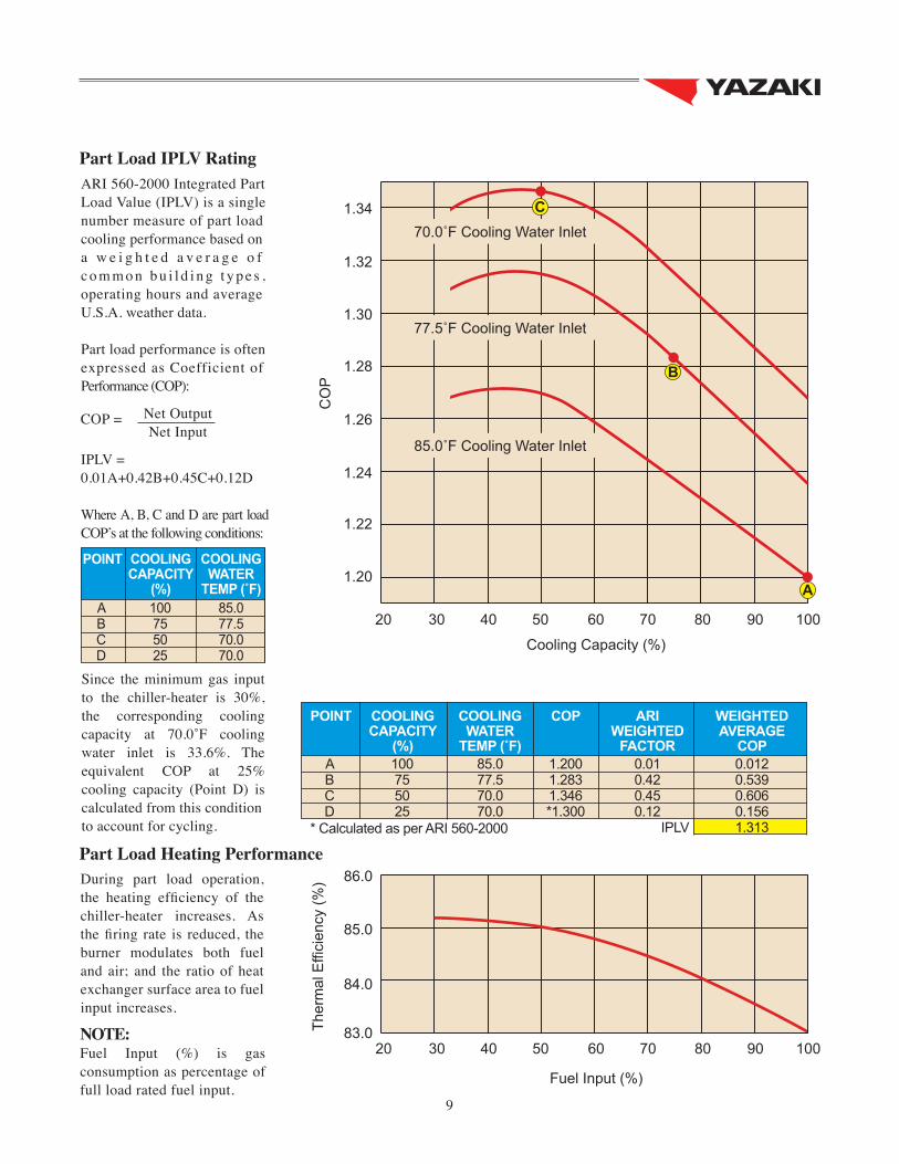
ARI 560-2000 Integrated Part Load Value (IPLV) is a single number measure of part load cooling performance based on a w e i g h t e d a v e r a g e o f c o m m o n b u i l d i n g t y p e s , operating hours and average U.S.A. weather data.
Part load performance is often expressed as Coefficient of Performance (COP):
IPLV =0.01A+0.42B+0.45C+0.12D
Where A, B, C and D are part load COP’s at the following conditions:
Part Load IPLV Rating
COP = Net Output Net Input
Since the minimum gas input to the chiller-heater is 30%, the corresponding cooling capacity at 70.0˚F cooling water inlet is 33.6%. The equivalent COP at 25% cooling capacity (Point D) is calculated from this conditionto account for cycling.
During part load operation, the heating efficiency of the chiller-heater increases. As the firing rate is reduced, the burner modulates both fuel and air; and the ratio of heat exchanger surface area to fuel input increases.
Part Load Heating Performance
COOLINGWATER
TEMP (˚F)
ARIWEIGHTED
FACTOR
COP WEIGHTEDAVERAGE
COP
COOLINGCAPACITY
(%)
POINT
100755025
ABCD
85.077.570.070.0
1.2001.2831.346*1.300
0.010.420.450.12
0.0120.5390.6060.1561.313IPLV* Calculated as per ARI 560-2000
9
NOTE:Fuel Input (%) is gas consumption as percentage of full load rated fuel input.

STANDARD JUNCTION BOX (JB) CONNECTIONS
Typical Piping
Typical Field Wiring
OPTIONAL CONTROL BOX (CB) CONNECTIONS
• Power supply.• Chilled/hot water and cooling water pump control.• Thermal overload interlocks from chilled/hot water pump, cooling water pump and cooling tower fan.
• Cooling water flow switch (FS2) input (Flow switch supplied by others).• Freeze protection switch (IF1) input for chilled/hot water (Temp. switch supplied by others).• Freeze protection switch (IF2) input for cooling water (Temp. switch supplied by others).• Exhaust fan control output.• Exhaust fan interlock.• Cooling tower sump level switch (LS).
• Cooling/heating mode status.• Chiller-heater operating status.• Chiller-heater standby status.• Dilution cycle status.• Burner operating status.• General shutdown alarm output.• External fault alarm output.• Main fault alarm output.• Burner flame failure alarm.• External fault interlock (Additional control supplied by others).• Earthquake switch shutdown.• Remote temperature control 4.5˚F setup/setback.
P P T
T
T
T
F
T P T P
M
P P
COOLING TOWERCWV
CHILLER-HEATER
CHILLED/HOT WATER PUMP
COOLING WATER PUMP
Supply Return
IF1(Optional)
IF2 (Optional)
Drain
Water Supply
CTS
CWTS
GasInlet
FlushValve
Drain
LS (Optional)LS (Optional)
Water Supply
P FT
SYMBOL DESCRIPTIONSYMBOL DESCRIPTIONSYMBOL DESCRIPTIONSYMBOL DESCRIPTIONSYMBOL DESCRIPTION
Temp. gauge
Expansion joint
Pressure gauge
Strainer
Gas meter
Relief valve
Reducing valve
Expansion tank
Check valve
Manual valveAIR
HANDLINGUNIT
FAN COILUNIT
FAN COILUNIT
Drain
Drain
Air VentFlushValve
Drain
Chilled/Hot Water Outlet
Chilled/Hot Water Intlet
Cooling Water Inlet
Cooling Water Outlet
10
OPTIONAL JUNCTION BOX (JB) CONNECTIONS• Remote cooling/heating mode selection.• Remote start/stop selection.• Cooling tower fan control output (Alternative to CTS).
COOLING WATERPUMP
COOLING TOWER
SYMBOL DESCRIPTION SYMBOL DESCRIPTION
IF1
IF2
CWTS
Chilled/hot water freeze switch CTS Cooling tower switch
Cooling water temperature switch CWV Cooling water control valve
Cooling water freeze switch LS Level switch
CWV
CHILLER-HEATER
IF1 (Optional)
IF2 (Optional)
CTS
CWTS
Power Supply(208V or 230V, 60Hz, 3ph)
POWERBOX
(Suppliedby
Others)
FUSED DISCONNECTS
LS (Optional)LS (Optional)
WIRING (Number of Conductors)
M
CHILLED/HOTWATERPUMP OPTIONAL
JUNCTION BOXCONNECTIONS
OPTIONALCONTROL BOXCONNECTIONS
CB
JB

Dimensions (CH-MG Series)
All dimensions in inches
12.9
14.313.87.7
62.262.276.8 8.78.3
8.7 88
.2 (
H)
20.6
2.02.0
87.6
45.4 16.3
17.7144.2 (L) 2.3
3.5
73.3
(W
)
75.6
34.7 13
.0
50.6
11.8
13.8
37.7
17.4
Cooling wateroutlet 5 flange
Chilled/hot wateroutlet 4 flange
Chilled/hot waterinlet 4 flange
REAR VIEW
EXHAUST VENT FLANGE DETAILS
Connect Class B venting system to exhaustvent flange for indoor installations
Cooling waterinlet 5 flange
Gas inlet 2 flange
Condensatedrain 1/2 tube
TOP VIEW
RIGHT SIDE VIEW
Vent CapExhaust vent flange
Field wiringjunction box
CH-MG150
NOTES:1. All pipe connections are ANSI Class 150 flanges.2. indicates anchor bolt location.3. Ensure that minimum clearance space is provided for chiller-heater maintenance (length 40 in., above 40 in. and sides 28 in.).4. Provide maintence clearance for tube removal in front (preferred) or rear of chiller-heater.
FRONT VIEW
56.0
SIDE
Front
Rear
Left
Right
CLEARANCE (IN)
115 (Note 4)
40
28
28
15.7 10 holes10 mm dia.
62.262.280.7 8.78.3
8.7 97
.6 (
H)
20.5
2.02.0
89.6
39.1 16.3
15.7
17.7147.0 (L) 2.3
3.5
77.2
(W
)
58.5 11
.8
13.8
7.7
25.6
13.0
13.018.0
3.328.1
55.9
37.8
85.3
TOP VIEW
RIGHT SIDE VIEWFRONT VIEW REAR VIEW
EXHAST VENT FLANGE DETAILS
Vent CapExhaust vent flange
Field wiringjunction box Connect Class B venting system to exhaust
vent flange for indoor installations
Cooling waterinlet 6 flange Cooling water
outlet 6 flange
Chilled/hot waterinlet 5 flange
Gas inlet 2 flange
Condensatedrain 1/2 tube
NOTES:1. All pipe connections are ANSI Class 150 flanges.2. indicates anchor bolt location.3. Ensure that minimum clearance space is provided for chiller-heater maintenance (length 40 in., above 40 in. and sides 28 in.).4. Provide maintence clearance for tube removal in front (preferred) or rear of chiller-heater.
CH-MG200
Chilled/hot wateroutlet 5 flange
SIDE
Front
Rear
Left
Right
CLEARANCE (IN)
115 (Note 4)
40
28
28
10 holes10 mm dia.
11

YAZAKI SALES REPRESENTATIVE/DISTRIBUTOR
For information concerning sales, operation, applicationor technical assistance, please contact your
Yazaki Sales Representative/Distributor or the following:
YAZAKI ENERGY SYSTEMS, INC.701 E. PLANO PARKWAY, SUITE 305,
PLANO, TEXAS 75074Phone: 469-229-5443
Fax: 469-229-5448Email: [email protected]
Web: www.yazakienergy.com
Yazaki reserves the right to discontinue, or change at any time,
specifications or designs without notice and without incurring obligations.SB-MGUL-1107
Top Related