


Languages
Pages
Legal


FYS4260/FYS9260: Microsystems and Electronics Packaging and Interconnect
Thermal Management

Figure information preceeding page
Free convection thermoelectric cooler (Peltiercooler) with heat sink surface temperature contours, and rising warmer air and falling cooler air flow trajectories, predicted using a CFD analysis package, courtesy of NCI
"CFD Free Convection Peltier Cooler" by Heatlord - I created this model and CFD analysis for WikipediaPreviously published: http://www.novelconceptsinc.com. Licensed under CC BY-SA 3.0 via Wikipedia -http://en.wikipedia.org/wiki/File:CFD_Free_Convection_Peltier_Cooler.gif#/media/File:CFD_Free_Convection_Peltier_Cooler.gif
FYS4260/FYS9260 Frode Strisland 2

Learning objectives
• Types of heat transfer mechanisms• Approaches to cool electronics• One dimensional thermal resistance calculations to
estimate temperature and heat flow
• Background literature:– Halbo & Ohlckers Chapter 6 and 7– Harper: Thermal Management– Electronic Packaging and Interconnection Handbook 4th
ed.

Thermal management
• Heat is an unavoidable by-product of everyelectronic device and circuit.
• Heat leads to problems in electronics, and needsto be controlled thermal management
FYS4260/FYS9260 Frode Strisland 4

What causes heat generation in circuits?
• Semiconductor switching• Resistive heating• Energy conversion
• (there may be several other effects)
FYS4260/FYS9260 Frode Strisland 5

Heat generation:Semiconductor switching• The power P dissipated from a semiconductor
during switching is
• where– C = input capacitance in farads– V = peak-to-peak voltage swing of signals in volts– f = switiching frequenzy in Hertz.
FYS4260/FYS9260 Frode Strisland 6
P =CV2
2f

Heat generation:Semiconductor switching• Major challenge to keep power dissipation in
modern IC's low enough when the numberof switcing devices and f (the clockfrequency) increases.
• Strategies to make heat generationmanagable– Lower input capacitance (smaller dimensions)– Lower switching voltages (5.0 V 3V 1 V)– Efficient cooling strategies
FYS4260/FYS9260 Frode Strisland 7
P =CV2
2f
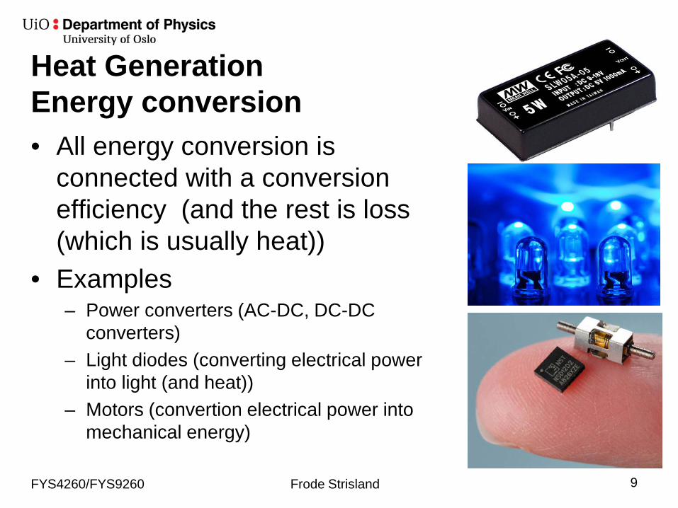
Heat GenerationEnergy conversion• All energy conversion is
connected with a conversionefficiency (and the rest is loss (which is usually heat))
• Examples– Power converters (AC-DC, DC-DC
converters)– Light diodes (converting electrical power
into light (and heat))– Motors (convertion electrical power into
mechanical energy)
FYS4260/FYS9260 Frode Strisland 9
Why Thermal Management?
Temperature increases lead to several unattractiveeffects, such as• Temperature changes circuit operation• Temperature affects the physical construction• Failure rates increases
FYS4260/FYS9260 Frode Strisland 10

Temperature effect on circuit operation• Increasing temperature of an active electronic
component changes its electrical parameters, such as gain, leakage and offset
• Passive components also typically change valueswith a temperature dependency, e.g. resistorsTemperature Coefficient of Resistance may varyfrom several ppm/K to several hundred ppm/K
• Exceeding manufacturerer specifications oftencause failures
FYS4260/FYS9260 Frode Strisland 11

Temperature effect on circuit operationGain tracking in an operational amplifier
If R2 physically is placed close to a heat dissipatingcomponent, theR2/R1 ratio willchange, and thusthe amplifier gain.
FYS4260/FYS9260 Frode Strisland 12
R1
R2
R3
Vin Vout
Gain tracking of R1 and R2
+
-

Temperature effects on PhysicalConstruction• Different materials have different coefficient of
tempermal expansion (CTE).• Thermal stresses occur when materials are
constrained during expansion or contraction.• Extended stress cycles may need to fatigue and
failure.
FYS4260/FYS9260 Frode Strisland 13
Thermal stresses might be permanent (for example due to soldering) or occur due to component (self-) heating

Failure rates increases with increasingtemperaturesThe failure rate F of an electronic component increases withtemperature, and can often be described by the Arrheniusequation derived in statistical mechanics
F = Ae−EAkBT
whereA = constantF = failure rateEA = activation energy (Joule)kB = Boltzmann's constantT = local temperature in Kelvin
FYS4260/FYS9260 Frode Strisland 14

Activation Energies for common FailureMechanisms in Electronic Circuits
FYS4260/FYS9260 Frode Strisland 15
Table 3.2 in Electronics Packagingand Interconnection Handbook 4th ed

Temperature dependence on Arrheniustype failure ratesThe relationship between failure rates at twodifferent temperatures can be expressed like:
F1F2
=Ae−
EAkBT1
Ae−EAkBT2
where F1 and F2 are the failure rates at temperatures T1 and T2, respectively.FYS4260/FYS9260 Frode Strisland 16

Temperature dependence onArrhenius type failure rates• Let us consider a device with an activation energy of
1.0 eV operating at 50°C when temperature increasesto 60°C. – Failure rate increase factor: 2.9
• With an activation energy of 0.65 eV (by many used as a rule of thumb), the failure rate increase factorbecomes 2:
The failure rate doubles for every 10 K increase in operation temperature
FYS4260/FYS9260 Frode Strisland 17
F1F2
=Ae−
EAkBT1
Ae−EAkBT2

Heat Flow Theory(The extremely condensed need-to-know version1)
Second law of Thermodynamics: Heat flowsspontaneously from a hotter region to a cooler region.
1) FYS4260 will only introduce simple 1-dimensional approximations. This will help you understand which effectsare important and which can be neglected.
FYS4260/FYS9260 Frode Strisland 18
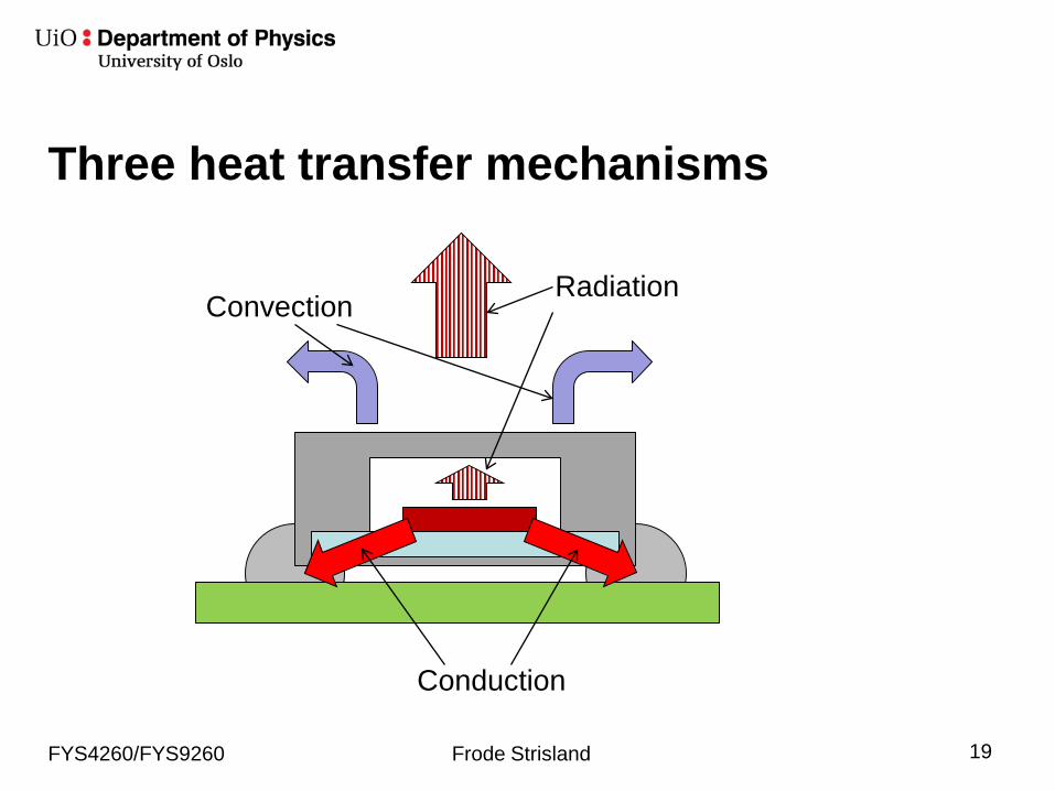
Three heat transfer mechanisms
FYS4260/FYS9260 Frode Strisland 19
Conduction
ConvectionRadiation

Heat transfer mechanisms: ConductionThermal conduction: Heat flows through a solid, liquid or gas, or between two media that are in intimate contact.
FYS4260/FYS9260 Frode Strisland 20

Microsopic view on heat conduction
Thermal conduction involves the transfer of kinetic thermalenergy from one electron to another with no visible global effects• Dielectrics: Heat transfer dominated by lattice vibrations• Metals: Added energy transport through free electrons
• Electrical and thermal conductivity closely linked• Liquids: Lower conduction than solids due to weaker
inter-molecular bonds• Gases: Even weaker (and random) inter-molecular bonds
causing gases to have poor thermal conductivity
FYS4260/FYS9260 Frode Strisland 21

Heat conduction:Fourier's law
The heat flow rate dQdt
equals the product ofthe cross-sectional area A of the area normal to the heat flow path multiplied withthe thermal conductivity of the medium and the temperature gradient:
dQdt
= −KA dTdx
whereK = thermal conductivity of medium [W/m K]A = cross-sectional area normal to heat flowpath [m2]T = temperature of medium [K]X = position [m]t = time [s]q = heat generated per unit volume [Joule/m3]
FYS4260/FYS9260 Frode Strisland 22
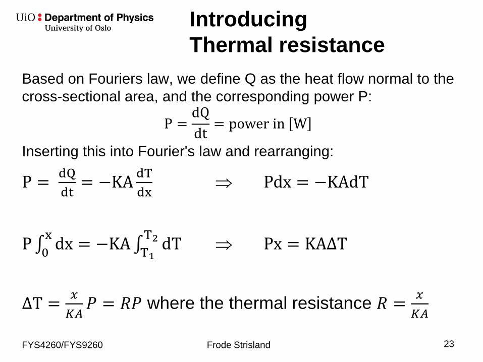
IntroducingThermal resistance
Based on Fouriers law, we define Q as the heat flow normal to thecross-sectional area, and the corresponding power P:
P =dQdt = power in W
Inserting this into Fourier's law and rearranging:
P = dQdt
= −KA dTdx
⇒ Pdx = −KAdT
P∫0x dx = −KA∫T1
T2 dT ⇒ Px = KA∆T
∆T = 𝑥𝑥𝐾𝐾𝐾𝐾𝑃𝑃 = 𝑅𝑅𝑃𝑃 where the thermal resistance 𝑅𝑅 = 𝑥𝑥
𝐾𝐾𝐾𝐾
FYS4260/FYS9260 Frode Strisland 23
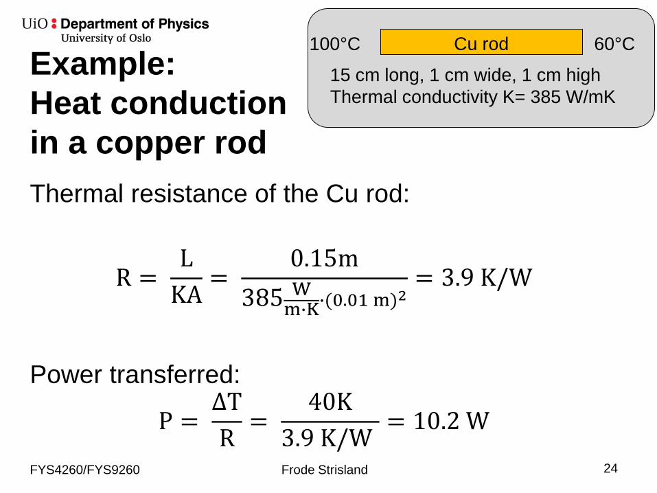
Example: Heat conductionin a copper rodThermal resistance of the Cu rod:
R =L
KA=
0.15m385 W
m�K�(0.01 m)2= 3.9 K/W
Power transferred:
P =∆TR
=40K
3.9 K/W= 10.2 W
FYS4260/FYS9260 Frode Strisland 24
Cu rod15 cm long, 1 cm wide, 1 cm highThermal conductivity K= 385 W/mK
100°C 60°C

Electrical Analogy to Thermal Networks
Thermal characteristics can be translated into thelanguage of electrical circuits!Ohm's law U=RI ⇒ ∆T = RPElectrical conductivity σ ⇒ thermal conductivity K
When several materials are stacked in series, theequivalent or total thermal resistance becomes thesum of the individual resistances
FYS4260/FYS9260 Frode Strisland 25

FYS4260/FYS9260 Frode Strisland 26
R1R2R3R4R5
Example: Thermalresistances in series
R1: thermal resistance of silicon dieR2: thermal resistance of conductive epoixy die attachR3: thermal resistance of alumina substrateR4: thermal resistance of substrate attach (solder)R5: thermal resistance of copper caseTjunction: junction temperatureTcase: case temperature

FYS4260/FYS9260 Frode Strisland 27
R1R2R3R4R5
Example: Thermalresistances in series
∆T = Tjunction − Tcase= R1 + R2 + R3 + R4 + R5 P= RTotP
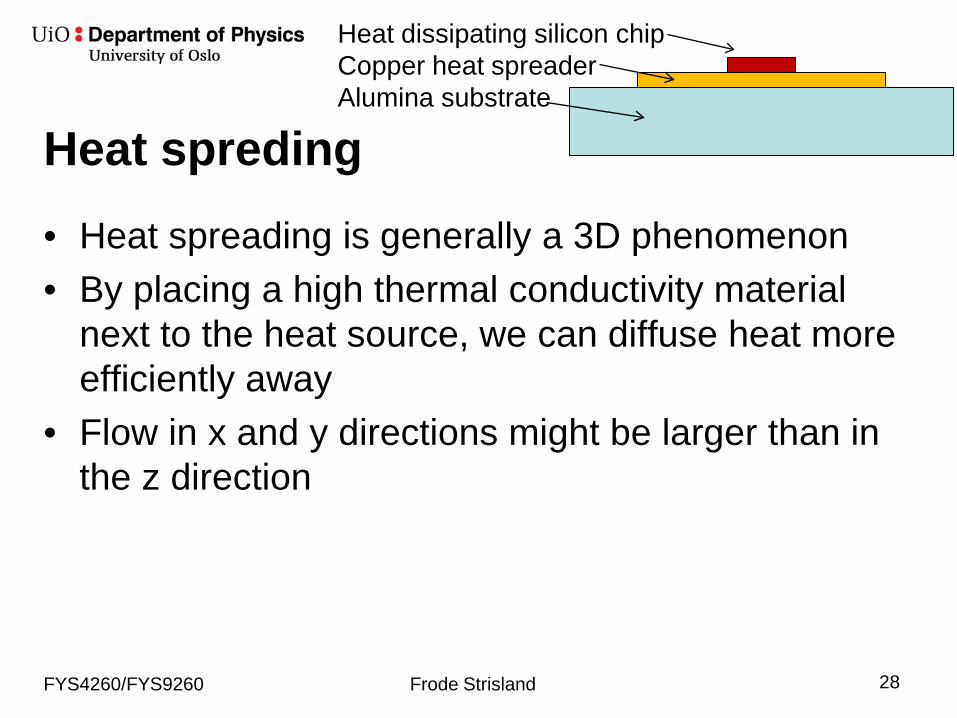
Heat spreding• Heat spreading is generally a 3D phenomenon• By placing a high thermal conductivity material
next to the heat source, we can diffuse heat more efficiently away
• Flow in x and y directions might be larger than in the z direction
FYS4260/FYS9260 Frode Strisland 28
Heat dissipating silicon chipCopper heat spreaderAlumina substrate
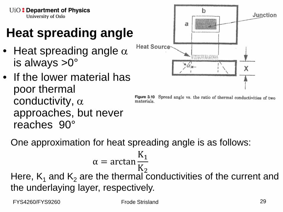
One approximation for heat spreading angle is as follows:
Here, K1 and K2 are the thermal conductivities of the current and the underlaying layer, respectively.
• Heat spreading angle αis always >0°
• If the lower material has poor thermalconductivity, αapproaches, but never reaches 90°
FYS4260/FYS9260 Frode Strisland 29
Heat spreading angle
α = arctanK1
K2
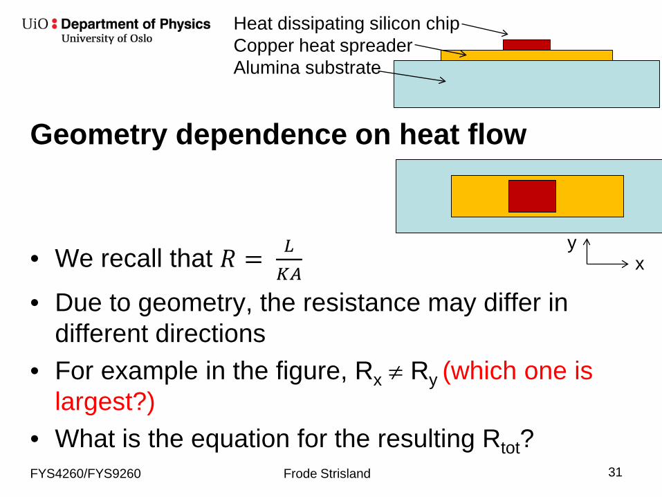
Geometry dependence on heat flow
• We recall that 𝑅𝑅 = 𝐿𝐿𝐾𝐾𝐾𝐾
• Due to geometry, the resistance may differ in different directions
• For example in the figure, Rx ≠ Ry (which one is largest?)
• What is the equation for the resulting Rtot?FYS4260/FYS9260 Frode Strisland 31
Heat dissipating silicon chipCopper heat spreaderAlumina substrate
xy
Thermal networks withmore than on paths• If there is more than one heat path, the
equivalent thermal resistances can be consideredto the the parallel equivalent to electrical resistorsin parallel.
• Confer previous example:1
Rtot= 1
Rx+ 1
Ry
FYS4260/FYS9260 Frode Strisland 32

Slide 33
Thermal conductivity in PCBs
Table 6.9: Typical values for the effective thermal conductivity of different types of PCBs.
Type Effective thermal conductivity(W/m °C)
FR-4 without Cu 0.21 Cu conductor layer, 35 µm 1.72 layers, 35 µm 3.14 layers, 2 x 35 µm, 2 x 70 µm 15 - 25Metal base board, 0.5 mm core 50 - 100

Slide 34
Thermal Design, continued
Fig. 6.26: LLCC package with thermal solder lands and thermal vias connected to a metal core in the PCB.

Convection
• Convection is the transfer of thermal energybetween two surfaces as a consequence of a relative velocity between them.
• Convection only occurs in fluids, and the transfer mechanism is the mixing of fluids
• Most practical example: Interface between a solid surface and a fluid (usually air)
FYS4260/FYS9260 Frode Strisland 35
CUP heat sink and fan cooling system

Convection cooling due to Newtoniancooling• Convection cooling is also known as Newtonian
cooling, and is based on the assumption that the heat transfer factors are relatively temperature independent.
• In mathematical terms:𝑄𝑄𝑐𝑐 = ℎ𝑐𝑐𝐴𝐴𝑠𝑠 𝑇𝑇𝑠𝑠 − 𝑇𝑇𝐾𝐾 = ℎ𝑐𝑐𝐴𝐴𝑠𝑠∆𝑇𝑇
whereQc = heat transferred from a surface to ambient by convection[W]As = surface area (m2)Ts = suface temperature [K]TA = ambient temperature [K]hc = convection heat transfer coefficient [W/K m2]
FYS4260/FYS9260 Frode Strisland 36

Convection cooling (cont'd)The heat flow equation can be rearranged:
∆𝑇𝑇 =1
ℎ𝑐𝑐𝐴𝐴𝑠𝑠𝑄𝑄𝑐𝑐
From this, we can define the convective surfaceresistance
𝑅𝑅𝑠𝑠 =1
ℎ𝑐𝑐𝐴𝐴𝑠𝑠Observe that this is just a definition, not a law; theremperature coefficient actually depends ontemperatures, fluid velocity, viscosity, density and surface geometryFYS4260/FYS9260 Frode Strisland 37
Natural (free) and forced convection
• Natural convection: energy exchange causedentirely by differences in temperatures and densities causing fluidic movement
• Forced convection: The heat transfer is propelledby artificial means, e.g. fans.
FYS4260/FYS9260 Frode Strisland 38
FYS4260/FYS9260 Frode Strisland 39
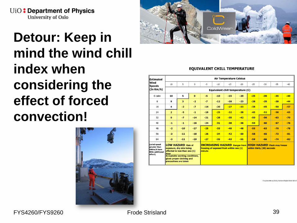
Detour: Keep in mind the wind chillindex whenconsidering theeffect of forcedconvection!

Estimating forced convection heat transfer coefficients• Engineering estimates are used, for example:
ℎ = 𝐵𝐵𝑣𝑣0.75
𝐿𝐿0.25
whereB = constant of air properties and surface configurationv = linear velocity of airL = characteristic lenght of surface in direction of flow
FYS4260/FYS9260 Frode Strisland 40

Geometry is importantin natural convection
• Flat plate heat flow
• Top surface hot
• Bottom surface hot
FYS4260/FYS9260 Frode Strisland 41
Relative heat transfer coefficients:
0.56
0.52
0.26

Radiation• All objects with temperature
above 0 K emit thermal radiation.• Radiation cooling is the transfer
of heat by electromagneticemission, mainly in infraredwavelengths
• Thermal radiation is a purelysurface related phenomenon, and we distinguish between– Black bodies– Non-black bodies
FYS4260/FYS9260 Frode Strisland 42
A thermal camera (IR camera) measures thelevels of thermal radiation
Black body
• A surface that absorbs the entire thermalradiation incident upon it, neither reflecting nor transmitting any of the incident radiation.
• The black body, at any given temperature, radiates more energy, both in the total spectrumand for each wavelenght interval than any othertemperature radiator
FYS4260/FYS9260 Frode Strisland 43
Emissivity• The emissivity ε is the ratio of radiated flux E
emitted by a body to that emitted by a black body Eb at the same temperature
𝜖𝜖 =𝐸𝐸𝐸𝐸𝑏𝑏
• Black body: ε = 1
FYS4260/FYS9260 Frode Strisland 44

Emissivities at different surfaces
• Surface treatment canchange radiationproperties completely!– Polished Aluminum ε = 0.03– Black anodisesd aluminum ε
= 0.86– Aluminum with 10 nm gold:
ε = 0.04-0.23
FYS4260/FYS9260 Frode Strisland 45

Stefan-Boltzman lawThe rate of emission of radiant energy from the surfaceof a body, R, can be expressed by the Stefan-Boltzmann law:
R = εσT4
R = QA
[W]
Q = εσAT4
whereε = surface emissivity [J/ s m2]σ = Stefan-Boltzmann constantQ = heat transferred [W]A = radiating surface area [m2]T = surface temperature [K]
FYS4260/FYS9260 Frode Strisland 46
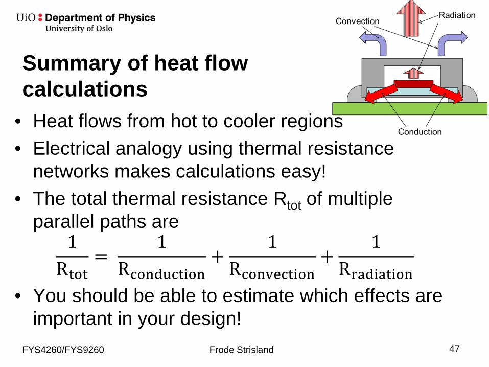
Summary of heat flowcalculations
• Heat flows from hot to cooler regions• Electrical analogy using thermal resistance
networks makes calculations easy!• The total thermal resistance Rtot of multiple
parallel paths are1
Rtot=
1Rconduction
+1
Rconvection+
1Rradiation
• You should be able to estimate which effects areimportant in your design!
FYS4260/FYS9260 Frode Strisland 47

Slide 48
Thermal Design, continued
•Thermal Resistance–Rjc: Thermal resistance
junction - case –Rjl: Thermal resistance
junction - lead–Rja: Thermal resistance
junction - ambient –Ta: Ambient temperature –Tj : Junction temperature
Fig. 6.23: Thermal model of an IC and package.
Slide 49
Strategies for improved cooling• Thermal vias• Cooling fins• Fan• Thermally conducting gas: helium, fluorocarbon• Liquid: water, fluorocarbon, oil• Boiling liquid• Heat pipe• Impingement cooling• Microbellows• Microgrooves
Slide 50
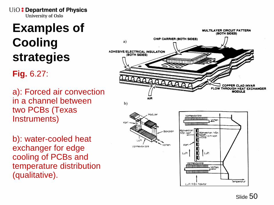
Examples of Cooling strategiesFig. 6.27:
a): Forced air convection in a channel between two PCBs (Texas Instruments)
b): water-cooled heat exchanger for edge cooling of PCBs and temperature distribution (qualitative).

08.10.99Electronic Pack….. Chapter 6: Printed Circuit Board Design Slide 51
Cooling liquid heat convection coefficientsFig. 6.28: Heat convection coefficient in different cooling media for natural convection, forced convection and boiling

Heat Pipes cooling
FYS4260/FYS9260 Frode Strisland 52
A heat sink (aluminium) with heat pipe (copper) and fan
"Heat Pipe Mechanism" by Zootalures. Licensed under CC BY-SA 2.5 via Wikimedia Commons -http://commons.wikimedia.org/wiki/File:Heat_Pipe_Mechanism.png#/media/File:Heat_Pipe_Mechanism.png

Slide 53
Microbellowscooling
Fig. 6.29: "Microbellows cooling": A jet of water or othercooling liquid impinges on the backside of the chip. Thebellow structure is necessary to accommodate thermalexpansion

Slide 54
Forced Liquid Cooling
Fig. 6.30: Cooling by forcing liquid through microscopic, etched channelsin the semiconductor chip [6.32]. The channels are approximately 400 µmdeep and 100 µm wide.
End of lecture:Thermal Management• Important issues:
– Thermal flow is complex and calculations or even advanced three dimensional calculations can only give estimates of the physical reality.
– Using thermal resistance calculations, you should be able to assess which effects are significant and which ones can be neglected.
Top Related