


Languages
Pages
Legal


©Ian Sommerville 1995 Software Engineering, 5th edition. Chapter 15 Slide 1
Function-oriented design
⊗ Design with functional unitswhich transform inputs tooutputs
©Ian Sommerville 1995 Software Engineering, 5th edition. Chapter 15 Slide 2
Objectives
⊗ To explain how a software design may berepresented as aset of functions which share state
⊗ To introduce notations for funciton-orienteddesign
⊗ To illustrate the function-oriented design processby example
⊗ To compare sequential, concurrent abd object-oriented design strategies

©Ian Sommerville 1995 Software Engineering, 5th edition. Chapter 15 Slide 3
Topics covered
⊗ data-flow design
⊗ Structural decomposition
⊗ Detailed design
⊗ A comparison of design strategies
©Ian Sommerville 1995 Software Engineering, 5th edition. Chapter 15 Slide 4
Function-oriented design
⊗ Practised informally since programming began
⊗ Thousands of systems have been developedusing this approach
⊗ Supported directly by most programminglanguages
⊗ Most design methods are functional in theirapproach
⊗ CASE tools are available for design support
©Ian Sommerville 1995 Software Engineering, 5th edition. Chapter 15 Slide 5
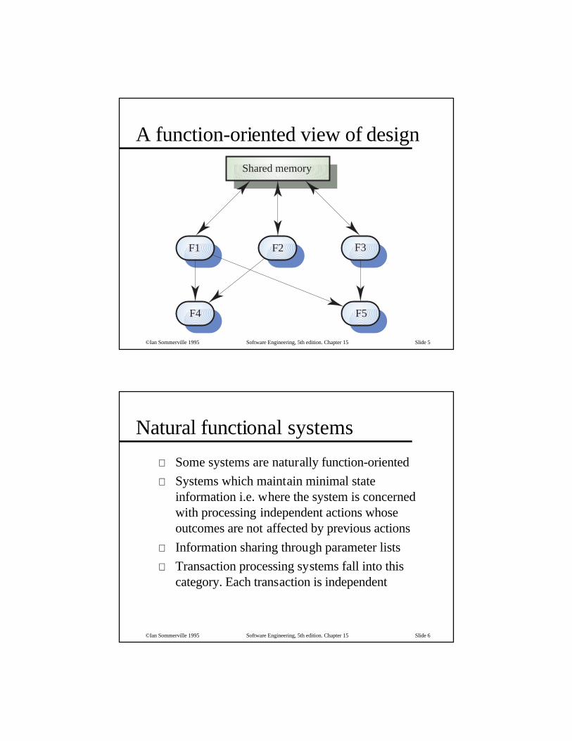
A function-oriented view of design
F2F1 F3
F4 F5
Shared memory
©Ian Sommerville 1995 Software Engineering, 5th edition. Chapter 15 Slide 6
Natural functional systems
⊗ Some systems are naturally function-oriented
⊗ Systems which maintain minimal stateinformation i.e. where the system is concernedwith processing independent actions whoseoutcomes are not affected by previous actions
⊗ Information sharing through parameter lists
⊗ Transaction processing systems fall into thiscategory. Each transaction is independent

©Ian Sommerville 1995 Software Engineering, 5th edition. Chapter 15 Slide 7
An ATM system design
⊗ Replace with portrait slide
©Ian Sommerville 1995 Software Engineering, 5th edition. Chapter 15 Slide 8
Functional and object-oriented design
⊗ For many types of application, object-orienteddeisgn is likely to lead to a more reliable andmaintainable system
⊗ Some applications maintain little state - function-oriented design is appropriate
⊗ Standards, methods and CASE tools forfunctional design are well-established
⊗ Existing systems must be maintained -function-oriented design will be practised wellinto the 21st century

©Ian Sommerville 1995 Software Engineering, 5th edition. Chapter 15 Slide 9
Functional design process
⊗ Data-flow design• Model the data processing in the system using data-flow
diagrams
⊗ Structural decomposition• Model how functions are decomposed to sub-functions using
graphical structure charts
⊗ Detailed design• The entities in the design and their interfaces are described in
detail. These may be recorded in a data dictionary and the designexpressed using a PDL
©Ian Sommerville 1995 Software Engineering, 5th edition. Chapter 15 Slide 10
Data flow diagrams
⊗ Show how an input data item is functionallytransformed by a system into an output dataitem
⊗ Are an integral part of many design methodsand are supported by many CASE systems
⊗ May be translated into either a sequential orparallel design. In a sequential design,processing elements are functions orprocedures; in a parallel design, processingelements are tasks or processes

©Ian Sommerville 1995 Software Engineering, 5th edition. Chapter 15 Slide 11
DFD notation
⊗ Rounded rectangle - function or transform
⊗ Rectangle - data store
⊗ Circles - user interactions with the system
⊗ Arrows - show direction of data flow
⊗ keywords and/ or. Used to link data flows
©Ian Sommerville 1995 Software Engineering, 5th edition. Chapter 15 Slide 12
Design report generator
⊗ Replace with portrait slide

©Ian Sommerville 1995 Software Engineering, 5th edition. Chapter 15 Slide 13
⊗ Structural decomposition is concerned withdeveloping a model of the design which shows thedynamic structure i.e. function calls
⊗ This is not the same as the static compositionstructure
⊗ The aim of the designer should be to derivedesign units which are highly cohesive andloosely coupled
⊗ In essence, a data flow diagram is converted to astructure chart
Structural decomposition
©Ian Sommerville 1995 Software Engineering, 5th edition. Chapter 15 Slide 14
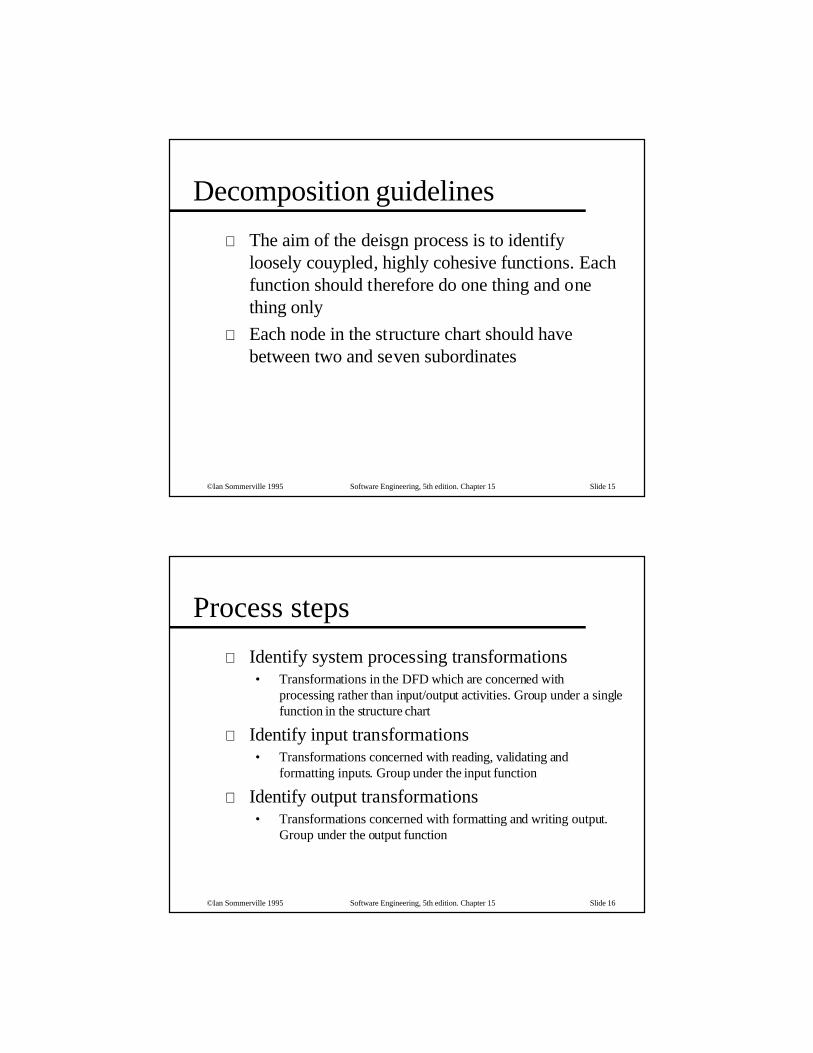
Decomposition guidelines
⊗ For business applications, the top-level structurechart may have four functions namely input,process, master-file-update and output
⊗ Data validation functions should be subordinate toan input function
⊗ Coordination and control should be theresponsibility of functions near the top of thehierarchy
©Ian Sommerville 1995 Software Engineering, 5th edition. Chapter 15 Slide 15
Decomposition guidelines
⊗ The aim of the deisgn process is to identifyloosely couypled, highly cohesive functions. Eachfunction should therefore do one thing and onething only
⊗ Each node in the structure chart should havebetween two and seven subordinates
©Ian Sommerville 1995 Software Engineering, 5th edition. Chapter 15 Slide 16
Process steps
⊗ Identify system processing transformations• Transformations in the DFD which are concerned with
processing rather than input/output activities. Group under a singlefunction in the structure chart
⊗ Identify input transformations• Transformations concerned with reading, validating and
formatting inputs. Group under the input function
⊗ Identify output transformations• Transformations concerned with formatting and writing output.
Group under the output function

©Ian Sommerville 1995 Software Engineering, 5th edition. Chapter 15 Slide 17
Initial structure chart
Producedesign reports
Collateentities
Generatereport
Get designentity names
Designname
Designentity
names
Designreport
entitynames
entitydata
entitydata
entitynames
©Ian Sommerville 1995 Software Engineering, 5th edition. Chapter 15 Slide 18
Expanded structure chartProduce
design reports
Collateentities
Generatereport
Get designentity names
entitynames
names
sortedentitydatanames
Get designname
Get entitynames
Sort entitiesby name
Get entitydata
Sort entitiesby type
Produceintegrated report
Printreport
designname
entitynames
reportentitydata
designname
names
sortednames
entitydata
sortedentitydata
sortedentitydata
Integratedreport
sortedentitydata

©Ian Sommerville 1995 Software Engineering, 5th edition. Chapter 15 Slide 19
Final structure chart
Datadictionary
Producedesign reports
Collateentities
Generatereport
Get designentity names
entitynames
names
sortedentitydatanames
Get designname
Get entitynames
Sort entitiesby name
Get entitydata
Sort entitiesby type
Produceintegrated report
Printreport
designname
entitynames
report
entitydata
designname
names
sortednames
entitydata
sortedentitydata
sortedentitydata
Integratedreport
Designdatabase
designname
entityname
Producelink report
Producenode report
Linkdata
Linkreport
Nodedata Node
report
sortedentitydata
©Ian Sommerville 1995 Software Engineering, 5th edition. Chapter 15 Slide 20
Detailed design
⊗ Concerned with producing a short designspecification (minispec) of each function. Thisshould describe the processing, inputs and outputs
⊗ These descriptions should be managed in a datadictionary
⊗ From these descriptions, detailed designdescriptions, expressed in a PDL or programminglanguage, can be produced

©Ian Sommerville 1995 Software Engineering, 5th edition. Chapter 15 Slide 21
Data dictionary entriesEntity name Type Description
Design name STRING The name of the design assigned by thedesign engineer.
Get design name FUNCTION Input: Design nameFunction: This function communicateswith the user to get the name of a designthat has been entered in the designdatabase.Output: Design name
Get entity names FUNCTION Input: Design nameFunction: Given a design name, thisfunction accesses the design database tofind the names of the entities (nodes andlinks) in that design.Output: Entity names
Sorted names ARRAY ofSTRING
A list of the names of the entities in adesign held in ascending alphabeticalorder.
©Ian Sommerville 1995 Software Engineering, 5th edition. Chapter 15 Slide 22
Design entity information
Get entitynames
Designdatabase
Sort entitynames
Transform name: Sort entity names (Namelist: in out Names)
Description: This transform takes a list of entity names andsorts them into ascending alphabetical order.Duplicates are removed from the list.
It is anticipated that the names will be randomly ordered andthat a maximum of 200 names need be sorted at one time.A quicksort algorithm is recommended.
Datadictionary
Get designname Design
name
Entitynames

©Ian Sommerville 1995 Software Engineering, 5th edition. Chapter 15 Slide 23
A comparison of design strategies
⊗ An example of an office information retrievalsystem (OIRS) is used to compare differentdesign strategies
⊗ Functional design, concurrent systems design andobject-oriented design are compared
⊗ The OIRS is an office system for documentmanagement. Users can file, maintain and retrievedocuments using it
©Ian Sommerville 1995 Software Engineering, 5th edition. Chapter 15 Slide 24
OIRS user interface
Get document
Put document
Search database
Add index
Delete index
Delete document
Known indexes Current indexesChapter 15
‘SE BOOK’
Document name
Qualifier
Documents4 documents in workspace
QUIT
CLEAR
Function-oriented design is an approach to software design where the designis decomposed into a set of interacting units where each unit has a clearlydefined function. By comparison with object-oriented design, the designcomponents in this approach are cohesive around a function whereasobject-oriented cohesion is around some abstract data entity.
Function-oriented design has probably been practised informally sinceprogramming began but it was only in the late 1960s and early 1970s that it
Operations
NEW STYLE

©Ian Sommerville 1995 Software Engineering, 5th edition. Chapter 15 Slide 25
⊗ Operation field.• Pull-down menu allowing an operation to be selected.
⊗ Known and current indexes fields• Pull-down menus of indexes
⊗ Document name.• Name under which the document is to be filed.
⊗ Qualifier field• Pattern used in retrieval.
⊗ Current workspace• Contains the documents currently being used. May be edited with
word processor
Interface description
©Ian Sommerville 1995 Software Engineering, 5th edition. Chapter 15 Slide 26
OIRS inputs and outputs
OIRSDocumentdatabase
Documentdatabase
Currentworkspace
Currentworkspace
User command
Status message
and
and
or
and
©Ian Sommerville 1995 Software Engineering, 5th edition. Chapter 15 Slide 27
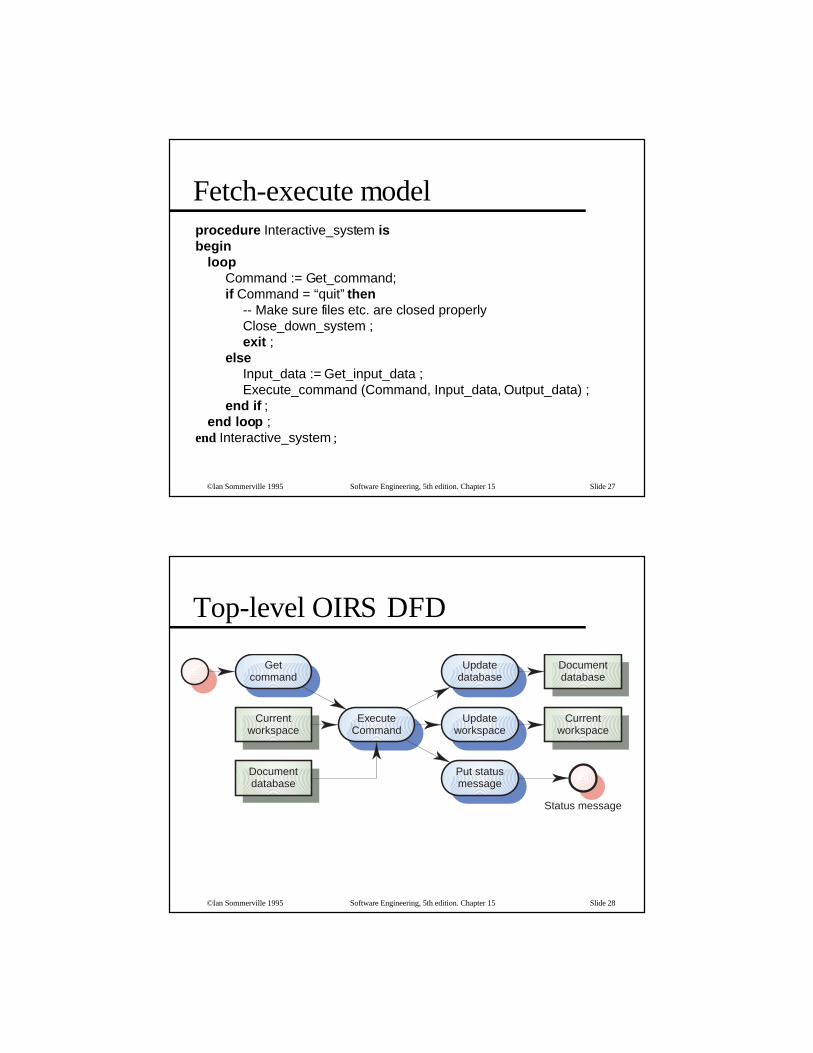
Fetch-execute modelprocedure Interactive_system isbegin
loopCommand := Get_command;if Command = “quit” then
-- Make sure files etc. are closed properlyClose_down_system ;exit ;
elseInput_data := Get_input_data ;Execute_command (Command, Input_data, Output_data) ;
end if ;end loop ;
end Interactive_system ;
©Ian Sommerville 1995 Software Engineering, 5th edition. Chapter 15 Slide 28
Top-level OIRS DFD
Getcommand
Updatedatabase
Documentdatabase
Currentworkspace
ExecuteCommand
Updateworkspace
Currentworkspace
Documentdatabase
Put statusmessage
Status message

©Ian Sommerville 1995 Software Engineering, 5th edition. Chapter 15 Slide 29
⊗ What strategy should be adopted indecomposing Execute command?
⊗ Are the input and output data flows processedindependently or are they inter-dependent. Ifindependent, there should be a centraltransform for each processing unit
⊗ Is the central transform a series of transforms?If so, each logical element in the series shouldbe a single transformation
Design decisions
©Ian Sommerville 1995 Software Engineering, 5th edition. Chapter 15 Slide 30
Execute command DFD
Identifycommand type
Updateindex
Updatedatabase
Updateworkspace
Knownindexes
Usercommand
Index updatecommand
Workspace updatecommand
Workspace
Selecteddocument
Statusmessage
Workspace Statusmessage
Databaseupdate request
Workspace
SelecteddocumentDB
updatecommand

©Ian Sommerville 1995 Software Engineering, 5th edition. Chapter 15 Slide 31
OIRS design description
⊗ Replace with portrait slide
©Ian Sommerville 1995 Software Engineering, 5th edition. Chapter 15 Slide 32
⊗ Data flow diagrams explicitly exclude controlinformation. They can be implemented directlyas concurrent processes.
⊗ Logical groups of transformations can also beimplemented as concurrent processes e.g.input data collection and checking
⊗ The OIRS system can be implemented as aconcurrent system with command input,execution and status reporting implemented asseparate tasks
Concurrent systems design

©Ian Sommerville 1995 Software Engineering, 5th edition. Chapter 15 Slide 33
OIRS process decomposition
©Ian Sommerville 1995 Software Engineering, 5th edition. Chapter 15 Slide 34
Detailed process designprocedure Office_system is
task Get_command ; task Process_command is entry Command_menu ; entry Display_indexes ; entry Edit_qualifier ; -- Additional entries here. One for each command end Process_commands ; task Output_message is entry Message_available ; end Output_message ; task Workspace_editor is entry Enter ; entry Leave ; end Workspace_editor ;

©Ian Sommerville 1995 Software Engineering, 5th edition. Chapter 15 Slide 35
Detailed process design
⊗ Replace with portrait slide
©Ian Sommerville 1995 Software Engineering, 5th edition. Chapter 15 Slide 36
Object-oriented design
⊗ An object-oriented design focuses on the entitiesin the system rather than the data processingactivities
⊗ Simplified OOD here which illustrates a differentdecomposition
⊗ The initial decomposition was introduced inChapter 14 in the discussion of objectidentification

©Ian Sommerville 1995 Software Engineering, 5th edition. Chapter 15 Slide 37
Preliminary object identification
©Ian Sommerville 1995 Software Engineering, 5th edition. Chapter 15 Slide 38
New objects required
⊗ Workspace• Corresponds to the user’s workspace and provides operations to
add and remove documents from the workspace
⊗ Index list• Provides facilities to manage a list of indexes
⊗ Document database• Corresponds to the database of documents. provides search and
retrieval operations

©Ian Sommerville 1995 Software Engineering, 5th edition. Chapter 15 Slide 39
Additional OIRS objects
©Ian Sommerville 1995 Software Engineering, 5th edition. Chapter 15 Slide 40
Object refinement
⊗ Retrieval system does not provide services. Itcoordinates other objects. It has only attributes
⊗ Documents and indexes are explicitly named
⊗ The individual command components havebeen bundled into a single attribute Usercommand in Retrieval system
⊗ The User object has been replaced by the Displayobject

©Ian Sommerville 1995 Software Engineering, 5th edition. Chapter 15 Slide 41
Modified OIRS objects
Get commandPut message
Display
Command listButtonsKnown indexesCurrent indexesDoc. nameDoc. listQualifierWSpace status
Retrieval system
User commandWorkspaceKnown indexesCurrent indexes
©Ian Sommerville 1995 Software Engineering, 5th edition. Chapter 15 Slide 42
⊗ Function-oriented design relies on identifyingfunctions which transform inputs to outputs
⊗ Many business systems are transaction processingsystems which are naturally functional
⊗ The functional design process involves identifyingdata transformations, decomposing functions intosub-functions and describing these in detail
35
Key points

©Ian Sommerville 1995 Software Engineering, 5th edition. Chapter 15 Slide 43
Key points
⊗ Data-flow diagrams are a means of documentingend-to-end data flow. Structure charts represent thedynamic hierarchy of function calls
⊗ Data flow diagrams can be implemented directlyas cooperating sequential processes
⊗ Functional and object-oriented design result indifferent system decompositions. However, aheterogeous approach to design is often necessary
Top Related