


Languages
Pages
Legal


Fukushima Fuels and Materials Department

FBR (Fast Breeder Reactor) is a fast neutron reactor designedto breed fuels by producing fissile materials.
FBR usually uses a uranium and plutonium mixed oxide(MOX) fuel core. The plutonium can be supplied from spentfuels of light-water reactor (LWR) and FBR by reprocessing.Therefore, the FBR is the key technology for Japan from theview of energy security and effective utilization of resources.
JAEA promotes R&Ds of FBR cycle system, i.e. FBR plant,
fuels and materials for FBR, reprocessing and disposal of highlevel waste.
Outline of FBR
R&D activity in FMD
The experimental fast reactor “JOYO”
AGF(Alpha-Gamma Facility)
Core part in JOYO
MMF(Materials Monitoring Facility)
FMF(Fuels Monitoring Facility)
PFRF(Plutonium Fuel Research Facility)
R&Ds of the high-performance fuels (nitride fuels etc…)
Design, manufacturing and inspection of fuel pins for irradiation test in JOYO and JMTR
PIEs of fuel assemblies and fuel pins and analysis of their irradiation behavior
Material sampling from fuel assemblies for PIEs in AGF and MMF
The experimental fast reactor “JOYO” was
constructed to achieve technical experience for
future FBR. In addition, irradiation test of advanced
fuels and materials have been carried out.
Higher burn-up of nuclear fuels is required for FBR with an high economical efficiency. Since coreconditions in FBR such as temperature and neutron fluencies are much more severe than in LWR, thefuels and materials during irradiation up to high burn-up should be newly investigated.
To satisfy these needs, FMD has investigated the irradiation behaviors of fuels and materials for FBRby the various post-irradiation examinations (PIEs) of fuels and materials irradiated in experimentalreactors (JOYO, JMTR and others). FMD has achieved a lot of reliable data which can be reflected tothe nuclear design of FBR.
Based on these technology and experiences, FMD also promotes R&Ds of the high-performancefuels and materials.
FMD has four hot laboratories ; FMF, AGF, MMF and PFRF.
R&Ds of nuclear fuels
Fuel pellet
Fuel pin
Cladding materials
Fuel assembly
R&D of nuclear fuels and materials for FBR in FMD*
R&Ds of the high-performance fuels (oxide fuels)
PIEs of nuclear fuels and analysis of their irradiation behavior
※FMD:Fukushima Fuels and Materials Department
PIEs of core/structural materials and analysis of their irradiation behavior
R&Ds of the high-performance materials
R&Ds of materials
R&Ds of fuel assemblies
R&Ds of fuel pins

Outcomes from PIEs and R&D activities in FMD
Both non-destructive and
destructive tests for fuel assembly
irradiated in experimental fast
reactor, JOYO, are carried out to
evaluate the effect of irradiation.
Fuels and materials irradiated as
a fuel assembly in JOYO are
transferred for the intermediate
inspection. Irradiated specimens are
re-assembled and reloaded into
JOYO after the inspection, making it
possible to achieve higher burn-up
of fuels and obtain irradiation data
of materials at higher dose.
Post Irradiation Examination of Fuel Assembly
Cross-section image of fuel assembly taken by X-ray CT
Fuel pin
Wrapper tube
Manipulator
Irradiated
specimen
s
Assembly
Collimator
X-ray detector
Protecting tube
Absorber pinsB4C pellets
PIE of control rod is carried out for
developing long-lived control rod.
Elements of the control rod are
composed of absorber pins, B4C
pellets, and outer protecting tube.
The X –ray CT images are utilized to
understand deformation behavior of
these elements of control rod due to
irradiation.
In addition, density measurements
and microstructural observations of
B4C pellets are performed to
evaluate the irradiation behavior of
control rod.
Post Irradiation Examination of Control rod
X-ray CT image of control rod
Microstructureof B4C pellet
25nm
X-ray source
X-ray computed
tomography (X-ray CT)
provides cross-sectional
image of a fuel assembly,
configuration of fuel pins,
and also distribution of
central void formed in the
irradiated fuel pellet.
The X –ray CT images are
obtained non-destructively
and utilized for evaluating
irradiation behavior of fuel
assembly.
1nm = 1 x 10⁻⁹m

Development of MAs-containing MOX fuel
MAs recovered from spent nuclear fuels are of
special concern because of their lasting radiotoxicity.
Therefore, recovery and recycling of MAs in FBR
should be key technology for the reduction of
environmental burden and a sustainable energy
supply for the future.
Appearances and ceramograph
image of Am-containing MOX fuels
Microstructure of
Am-containing
Inert matrix fuel
Thermal ionization mass
spectroscopy (TIMS) partially
installed in glove box
The fuel burn-ups of MOX fuels have been determined with
a high degree of accuracy by the measurements of uranium,
plutonium and Neodymium isotopes in irradiated fuels. The
transmutation behaviors of minor actinides (MAs: Np, Am and
Cm) have been also experimentally investigated.
Separated isotope solution
from irradiated nuclear fuel
solutions
PIEs of nuclear fuel
Melting temperature and source term of irradiated MOX
fuels have been investigated for the evaluation of fuel
behaviors under normal and accident conditions. The phase
relation, elements distribution and microstructure changes of
irradiated MOX fuels have been also investigated to
understand the mechanisms of the irradiation behavior.
Elemental distribution of Pu,
Am in irradiated MOX fuel
High frequency induction
furnace in shielded cell
Microstructure of
irradiated MOX fuel
Outcomes from PIEs and R&D activities in FMD
PIEs of uranium-plutonium mixed oxides (MOX) fuels for a
FBR are carried out, and their irradiation behavior are
evaluated for a fuel design.
The R&D of MAs-containing fuels, i.e. Am-
containing MOX fuel and inert matrix fuel such as
Cercer and Cermet fuels, have been carried out.
The MAs-containing fuels with good characteristics,
i.e. having no defects, a high density and a
homogeneity, were successfully fabricated by a
remote handling system.
Based on a concept of grain-boundary
engineering, the R&D of high performance
cladding materials are carried out for the
purposes of expanding its application areas
and improving properties of the existing core
structural materials.
Developmental austenitic steels with
extremely high density of coincidence site
lattice (CSL) boundary are successfully
fabricated by the modification of former
thermo-mechanical processing.
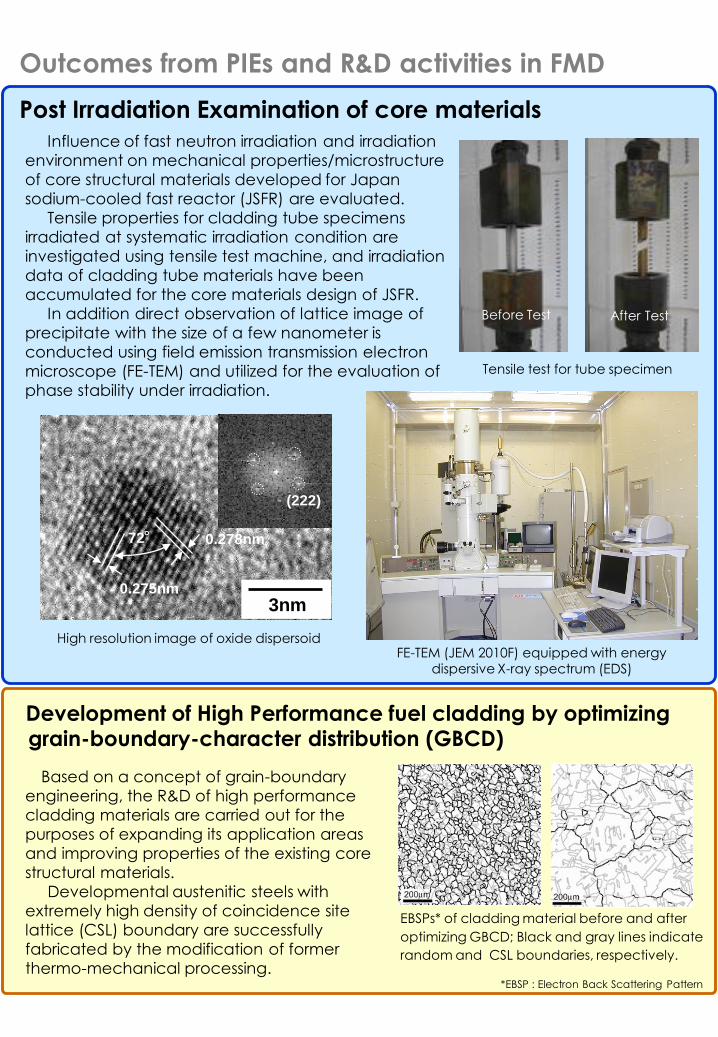
Influence of fast neutron irradiation and irradiation
environment on mechanical properties/microstructure
of core structural materials developed for Japan
sodium-cooled fast reactor (JSFR) are evaluated.
Tensile properties for cladding tube specimens
irradiated at systematic irradiation condition are
investigated using tensile test machine, and irradiation
data of cladding tube materials have been
accumulated for the core materials design of JSFR.
In addition direct observation of lattice image of
precipitate with the size of a few nanometer is
conducted using field emission transmission electron
microscope (FE-TEM) and utilized for the evaluation of
phase stability under irradiation.
3nm
0.278nm
0.275nm
72°
(222)
Post Irradiation Examination of core materials
Development of High Performance fuel cladding by optimizinggrain-boundary-character distribution (GBCD)
FE-TEM (JEM 2010F) equipped with energy dispersive X-ray spectrum (EDS)
High resolution image of oxide dispersoid
EBSPs* of cladding material before and after
optimizing GBCD; Black and gray lines indicate
random and CSL boundaries, respectively.
Tensile test for tube specimen
After TestBefore Test
Outcomes from PIEs and R&D activities in FMD
*EBSP : Electron Back Scattering Pattern

Glove box
Hot cell
A glove box has a highly air-tightness.Examinations of low-level radioactivefuels and materials can be carried outwith relative ease in a glove box throughthe acrylic window.
Equipments in hot laboratory
Examinations by glove box
Examinations by remote access
A cask is a shield-flask. FMD has thevarious cask specified based on weight,size and radioactive levels of specimens.Irradiated fuels and materials can besafely transported between the facilitiesby using the appropriate cask.
Concrete, iron and lead have the
shielding capability for radioactivity.
※
Transportation of irradiated specimens by using a cask
cask
Shield wall
The thick wall made of
concretes, iron or lead
which prevents
operators from exposure
Shielding window
The window made of
glass contained lead to
monitor the inside of cell
Master slave manipulator (MS)
Robotic arms to handle
specimens in the cell
Power manipulator
Robotic arms capable
to lift heavy objects
Overhead crane
Crane to deliver the
heavy objects
Testing device
The devices designed from
the viewpoint of resistance
to irradiation and remote
handling performance
The shield-cell is made of heavy concrete, iron or lead. It can keep radioactive materialsinside by means of controlling the inside atmosphere on negative-pressure. Since FMD has alot of the shield-cell, irradiated fuels and materials which have high radioactivity can behandled in it. The examinations and machine operations are carried out using remotehandling equipments such as power/master slave manipulators and overhead cranes.
Cask
Research facilities of fuels and materials
department (FMD) have been utilized by internal
/external researchers and engineers.
In Plutonium Fuel Research Facility (PFRF), one
of FMD facilities, R&D has been progressing on a
nitride fuel and a metallic fuel for fast reactor
application. In addition, fundamental studies on
transmutation target for long-lives minor actinides
and on pyrochemical reprocessing using molten
salt have been carried out.
Although nitride fuel and a metallic fuel have
several advantages compared with oxide fuel in
terms of elemental density of heavy metal and
thermal conductivity, they easily react with oxygen
and moisture.
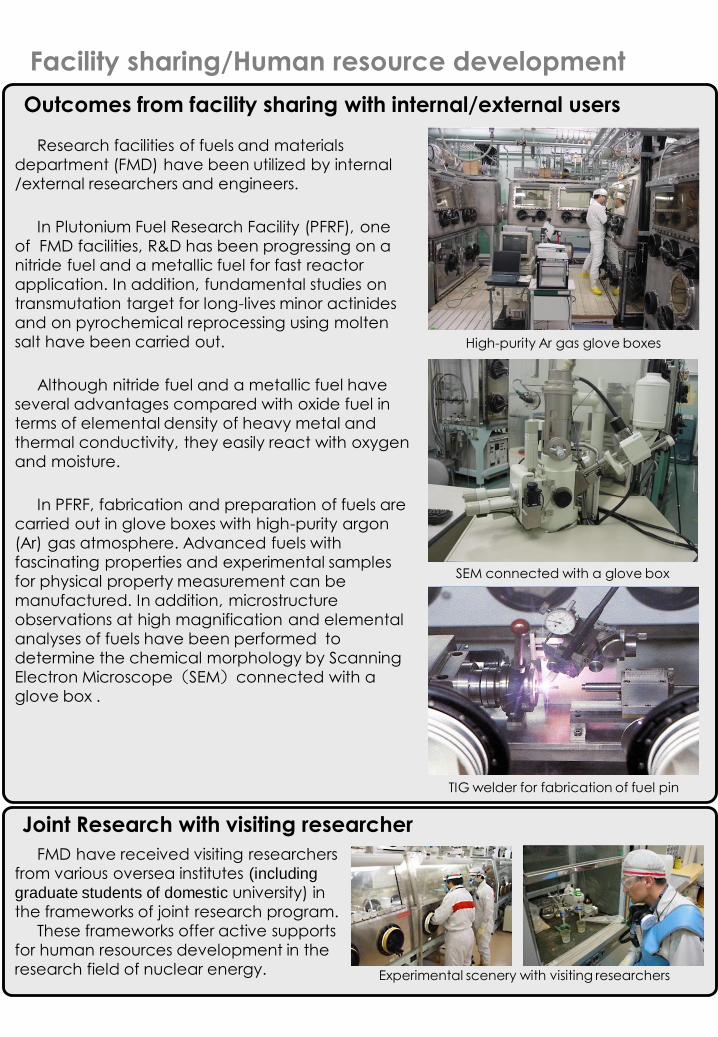
In PFRF, fabrication and preparation of fuels are
carried out in glove boxes with high-purity argon
(Ar) gas atmosphere. Advanced fuels with
fascinating properties and experimental samples
for physical property measurement can be
manufactured. In addition, microstructure
observations at high magnification and elemental
analyses of fuels have been performed to
determine the chemical morphology by Scanning
Electron Microscope(SEM)connected with a
glove box .
Facility sharing/Human resource development
TIG welder for fabrication of fuel pin
High-purity Ar gas glove boxes
FMD have received visiting researchers
from various oversea institutes (including
graduate students of domestic university) in
the frameworks of joint research program.
These frameworks offer active supports
for human resources development in the
research field of nuclear energy. Experimental scenery with visiting researchers
Joint Research with visiting researcher
SEM connected with a glove box
Outcomes from facility sharing with internal/external users
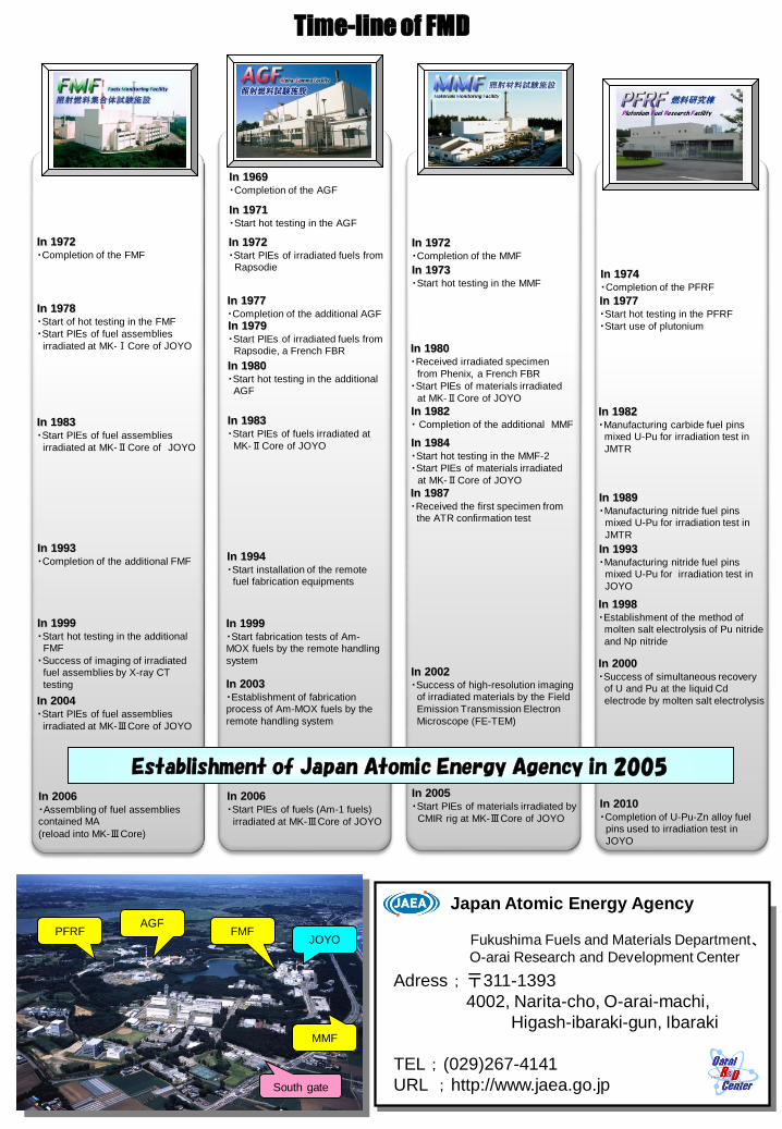
Time-line of FMD
Japan Atomic Energy Agency
Fukushima Fuels and Materials Department、O-arai Research and Development Center
South gate
PFRF
Adress ; 〒311-1393
4002, Narita-cho, O-arai-machi,
Higash-ibaraki-gun, Ibaraki
TEL ; (029)267-4141
URL ; http://www.jaea.go.jp
AGFFMF
MMF
JOYO
In 2006・Start PIEs of fuels (Am-1 fuels)
irradiated at MK-ⅢCore of JOYO
In 1969・Completion of the AGF
In 1971 ・Start hot testing in the AGF
In 1972 ・Start PIEs of irradiated fuels from
Rapsodie
In 1977・Completion of the additional AGF
In 1979・Start PIEs of irradiated fuels from
Rapsodie, a French FBR
In 1980・Start hot testing in the additional
AGF
In 1983・Start PIEs of fuels irradiated at
MK-ⅡCore of JOYO
In 1994・Start installation of the remote
fuel fabrication equipments
In 1972・Completion of the MMF
In 1973 ・Start hot testing in the MMF
In 1980 ・Received irradiated specimen
from Phenix, a French FBR
・Start PIEs of materials irradiated
at MK-ⅡCore of JOYO
In 1982・ Completion of the additional MMF
In 1984・Start hot testing in the MMF-2
・Start PIEs of materials irradiated
at MK-ⅡCore of JOYO
In 1987・Received the first specimen from
the ATR confirmation test
In 2002・Success of high-resolution imaging
of irradiated materials by the Field
Emission Transmission Electron
Microscope (FE-TEM)
In 2005・Start PIEs of materials irradiated by
CMIR rig at MK-ⅢCore of JOYO
Establishment of Japan Atomic Energy Agency in 2005
In 1974・Completion of the PFRF
In 1977 ・Start hot testing in the PFRF
・Start use of plutonium
In 1982 ・Manufacturing carbide fuel pins
mixed U-Pu for irradiation test in
JMTR
In 1989 ・Manufacturing nitride fuel pins
mixed U-Pu for irradiation test in
JMTR
In 1993・Manufacturing nitride fuel pins
mixed U-Pu for irradiation test in
JOYO
In 2006・Assembling of fuel assemblies contained MA
(reload into MK-ⅢCore)
In 1972・Completion of the FMF
In 1978・Start of hot testing in the FMF
・Start PIEs of fuel assemblies
irradiated at MK-ⅠCore of JOYO
In 1983・Start PIEs of fuel assemblies
irradiated at MK-ⅡCore of JOYO
In 1993・Completion of the additional FMF
In 1999・Start hot testing in the additional
FMF
・Success of imaging of irradiatedfuel assemblies by X-ray CT
testing
In 2004・Start PIEs of fuel assemblies
irradiated at MK-ⅢCore of JOYO
Plutonium Fuel Research Facility
燃料研究棟
In 1998・Establishment of the method of
molten salt electrolysis of Pu nitride
and Np nitride
In 2000・Success of simultaneous recovery
of U and Pu at the liquid Cd
electrode by molten salt electrolysis
In 2010・Completion of U-Pu-Zn alloy fuel
pins used to irradiation test in
JOYO
In 1999・Start fabrication tests of Am-MOX fuels by the remote handling
system
In 2003・Establishment of fabrication process of Am-MOX fuels by the
remote handling system
Top Related