


Languages
Pages
Legal

SERVICEMANUAL
Published in July 2010842LX111
2LXSM061Rev.1
FS-3040MFPFS-3140MFP
2LW/2LX
CONTENTS
1-1 Specifications1-1-1 Specifications ........................................................................................................................ 1-1-1
1-1-2 Parts names ..........................................................................................................................1-1-5
(1) Overall .............................................................................................................................. 1-1-5
(2) Operation panel ................................................................................................................1-1-6
1-1-3 Machine cross section ........................................................................................................... 1-1-7
1-2 Installation1-2-1 Installation environment......................................................................................................... 1-2-1
1-2-2 Unpacking.............................................................................................................................. 1-2-2
(1) Unpacking......................................................................................................................... 1-2-2
(2) Removing the tapes..........................................................................................................1-2-3
1-2-3 Installing the expansion memory (option) .............................................................................. 1-2-6
1-3 Maintenance Mode1-3-1 Maintenance mode ................................................................................................................1-3-1
(1) Executing a maintenance item .........................................................................................1-3-1
(2) Maintenance modes item list ............................................................................................ 1-3-2
(3) Contents of the maintenance mode items ........................................................................ 1-3-5
1-3-2 Service mode....................................................................................................................... 1-3-50
(1) Executing a service mode ..............................................................................................1-3-50
(2) Description of service mode ...........................................................................................1-3-51
1-4 Troubleshooting1-4-1 Paper misfeed detection........................................................................................................ 1-4-1
(1) Paper misfeed indication .................................................................................................. 1-4-1
(2) Paper misfeed detection condition ...................................................................................1-4-2
1-4-2 Self-diagnostic function ......................................................................................................... 1-4-5
(1) Self-diagnostic function ....................................................................................................1-4-5
(2) Self diagnostic codes........................................................................................................ 1-4-6
1-4-3 Image formation problems................................................................................................... 1-4-13
(1) Completely blank printout. ..............................................................................................1-4-14
(2) All-black printout. ............................................................................................................ 1-4-15
(3) Dropouts. ........................................................................................................................1-4-16
(4) Black dots. ...................................................................................................................... 1-4-16
(5) Black horizontal streaks..................................................................................................1-4-16
(6) Black vertical streaks......................................................................................................1-4-17
(7) Unsharpness. .................................................................................................................1-4-17
(8) Gray background. ...........................................................................................................1-4-17
(9) Dirt on the top edge or back of the paper. ...................................................................... 1-4-18
(10) Undulated printing at the right edge (scanning start position). .......................................1-4-18
1-4-4 Electric problems .................................................................................................................1-4-19
1-4-5 Mechanical problems...........................................................................................................1-4-25
1-4-6 Send error code................................................................................................................... 1-4-27
(1) Scan to SMB error codes ............................................................................................... 1-4-27
(2) Scan to FTP error codes ................................................................................................ 1-4-28
(3) Scan to E-mail error codes ............................................................................................. 1-4-28
(4) Network Twain error codes............................................................................................. 1-4-30
(5) Software trouble error codes .......................................................................................... 1-4-30

2LW/2LX
1-4-7 Error codes .......................................................................................................................... 1-4-31
(1) Error code....................................................................................................................... 1-4-31
(2) Table of general classification ........................................................................................1-4-32 (2-1) U004XX error code table: Interrupted phase B .......................................................................1-4-34
(2-2) U006XX error code table: Problems with the unit ...................................................................1-4-34
(2-3) U008XX error code table: Page transmission error.................................................................1-4-34
(2-4) U009XX error code table: Page reception error ......................................................................1-4-34
(2-5) U010XX error code table: G3 transmission.............................................................................1-4-35
(2-6) U011XX error code table: G3 reception ..................................................................................1-4-36
(2-7) U017XX error code table: V.34 transmission ..........................................................................1-4-37
(2-8) U018XX error code table: V.34 reception................................................................................1-4-37
(2-9) U044XX error code table: Encrypted transmission .................................................................1-4-37
1-5 Assembly and disassembly1-5-1 Precautions for assembly and disassembly........................................................................... 1-5-1
(1) Precautions.......................................................................................................................1-5-1
(2) Drum................................................................................................................................. 1-5-1
(3) Toner ................................................................................................................................1-5-1
(4) How to tell a genuine Kyocera Mita toner container .........................................................1-5-2
1-5-2 Outer covers ..........................................................................................................................1-5-3
(1) Detaching and refitting the right cover and left cover ....................................................... 1-5-3
1-5-3 Paper feed section................................................................................................................. 1-5-6
(1) Detaching and refitting the paper feed assembly (paper feed roller and pickup roller) .... 1-5-6
(2) Detaching and refitting the retard roller assembly ............................................................1-5-7
(3) Detaching and refitting the upper registration and lower roller ........................................ 1-5-8
(4) Detaching and refitting the MP paper feed roller ............................................................ 1-5-10
1-5-4 Optical section .....................................................................................................................1-5-11
(1) Detaching and refitting the Document processor ...........................................................1-5-11
(2) Detaching and refitting the scanner unit ......................................................................... 1-5-13
(3) Detaching and refitting the laser scanner unit ................................................................ 1-5-16
(4) Replacing the image scanner unit (ISU)......................................................................... 1-5-19
1-5-5 Developing section ..............................................................................................................1-5-25
(1) Detaching and refitting the developing unit ....................................................................1-5-25
1-5-6 Drum section ....................................................................................................................... 1-5-26
(1) Detaching and refitting the drum unit..............................................................................1-5-26
(2) Detaching and refitting the main charger unit .................................................................1-5-26
1-5-7 Transfer/separation section .................................................................................................1-5-27
(1) Detaching and refitting the transfer roller and separation brush unit..............................1-5-27
1-5-8 Fuser section ....................................................................................................................... 1-5-29
(1) Detaching and refitting the fuser unit..............................................................................1-5-29
1-5-9 PWBs................................................................................................................................... 1-5-30
(1) Detaching and refitting the engine PWB......................................................................... 1-5-30
(2) Detaching and refitting the main PWB............................................................................ 1-5-34
(3) Detaching and refitting the power source PWB..............................................................1-5-37
(4) Detaching and refitting the FAX control PWB.................................................................1-5-42
1-5-10 Others .................................................................................................................................. 1-5-43
(1) Detaching and refitting the paper feed drive unit............................................................ 1-5-43
(2) Detaching and refitting the main drive unit ..................................................................... 1-5-45
(3) Direction of installing the principal fan motors ................................................................ 1-5-46

2LW/2LX
1-5-11 Document processor ...........................................................................................................1-5-47
(1) Detaching and refitting the DP rear cover and DP front cover .......................................1-5-47
(2) Detaching and refitting the DP drive PWB...................................................................... 1-5-48
(3) Detaching and refitting the DP forwarding pulley assembly
and DP separation pad assembly. .................................................................................. 1-5-49
1-6 Requirements on PWB Replacement1-6-1 Upgrading the firmware ......................................................................................................... 1-6-1
1-6-2 Remarks on engine PWB replacement ................................................................................. 1-6-2
2-1 Mechanical Construction2-1-1 Paper feed/conveying section ............................................................................................... 2-1-1
(1) Cassette paper feed section.............................................................................................2-1-1
(2) MP tray paper feed section............................................................................................... 2-1-3
(3) Paper conveying section .................................................................................................. 2-1-4
2-1-2 Drum section ......................................................................................................................... 2-1-5
2-1-3 Optical section .......................................................................................................................2-1-6
(1) Scanner unit ..................................................................................................................... 2-1-6
(2) Image scanner unit (ISU).................................................................................................. 2-1-7
(3) Laser scanner unit ............................................................................................................ 2-1-9
2-1-4 Developing section ..............................................................................................................2-1-11
2-1-5 Transfer/Separation section ................................................................................................ 2-1-13
2-1-6 Cleaning section ..................................................................................................................2-1-14
2-1-7 Fuser section ....................................................................................................................... 2-1-16
2-1-8 Eject/Rear unit section......................................................................................................... 2-1-18
2-1-9 Duplex conveying section....................................................................................................2-1-20
2-1-10 Document processor ...........................................................................................................2-1-21
(1) Original feed section.......................................................................................................2-1-21
(2) Original conveying section..............................................................................................2-1-22
(3) Original switchback/eject sections.................................................................................. 2-1-23
2-2 Electrical Parts Layout2-2-1 Electrical parts layout ............................................................................................................ 2-2-1
(1) PWBs................................................................................................................................2-2-1
(2) Switches and sensors.......................................................................................................2-2-3
(3) Motors............................................................................................................................... 2-2-5
(4) Other electrical components.............................................................................................2-2-6
(5) Document processor ........................................................................................................ 2-2-7
2-3 Operation of the PWBs2-3-1 Power source PWB ............................................................................................................... 2-3-1
2-3-2 Engine PWB ..........................................................................................................................2-3-3
2-3-3 Main PWB.............................................................................................................................. 2-3-7
2-3-4 Connect-L PWB................................................................................................................... 2-3-13
2-3-5 Connect-R PWB ..................................................................................................................2-3-17
2-3-6 DP drive PWB...................................................................................................................... 2-3-20

2LW/2LX
2-4 Appendixes2-4-1 Appendixes............................................................................................................................ 2-4-1
(1) Wiring diagram ................................................................................................................. 2-4-1
(2) Repetitive defects gauge .................................................................................................. 2-4-3
(3) Maintenance kits............................................................................................................... 2-4-4
(4) Firmware Environment Commands .................................................................................. 2-4-5

2LW/2LX-1
1-1-1 Specifications
Basic functions
Item Specifications
Type Desktop
Printing method Electrophotography by semiconductor laser, single drum system
Originals Sheet, Book, 3-dimensional objects (maximum original size: Folio/Legal)
Original feed system Contact glass: fixed
Paper weight Cassette 60 to 120 g/m2 (Duplex: 60 to 120 g/m2)
MP tray 60 to 220 g/m2
Paper type Cassette Plain, Recycled, Preprinted, Bond, Color (Colour), Prepunched, Letterhead, High Quality, Custom 1 to 8 (Duplex: Same as simplex)
MP tray Plain, Transparency, Rough, Vellum, Labels, Recycled, Preprinted, Bond, Cardstock, Color (Colour), Prepunched, Letterhead, Thick, Envelope, High Quality, Custom 1 to 8
Paper size Cassette A4, B5, A5, A6, Legal, Letter, Statement, Executive, Oficio II, Folio, 16K, Custom
MP tray A4, B5, B5(ISO), A5, A6, B6, Envelope #10, Envelope #9, Envelope #6, Envelope Monarch, Envelope DL, Envelope C5, Hagaki,Oufuku Hagaki, Youkei 2, Youkei 4, Legal, Letter, Statement, Executive, Oficio II, Folio, 16K, Custom
Magnification ratios Manual mode: 25 - 400%, 1% incrementsAuto mode: 400%, 200%, 141%, 129%, 115%, 90%, 86%, 78%, 70%, 64%,
50%, 25%
Copying speed
Simplex A4R : 40 ppmLetterR : 42 ppmLegal : 33 ppmB5R : 33 ppmA5R/A6R : 22 ppm
Duplex A4R : 24.5 ppmLetterR : 26 ppmLegal : 16.5 ppmB5R : 24 ppmA5R : 21 ppm
First copy time(A4, feed from cassette)
7.0 second or less
Warm-up time(22°C 60%RH)
Power on: 22 second or lessRecovery from the low power mode: 10 second or lessRecovery from the sleep mode: 15 second or less
Paper capacity
Cassette 500 sheets (80g/m2)
MP tray 100 sheets (80 g/m2, plain paper, Letter/A4 or smaller)
Output tray capacity 500 heets (80g/m2)
Continuous printing 1 to 999 sheets
Scanning system Flat bed scanning by CCD image sensor
1-1-1

2LW/2LX-1
Photoconductor a-Si drum (diameter 30 mm)
Image write system Semiconductor laser (1 beam)
Charging system Contact charger roller method (positive charging)
Developing system Mono component dry developing methodToner replenishing: Automatic from the toner container
Transfer system Transfer roller (negative-charged)
Separation system Small diameter separation, discharger brush (negative-charged)
Cleaning system Counter blade cleaning + cleaning roller
Charge erasing system Exposure by eraser lamp (LED)
Fusing system Heat roller systemHeat source: halogen heaterAbnormally high temperature protection devices: thermostats
CPU PowerPC440 (667MHz)
Memory Standard 256MB
Maximum 768MB
Interface USB: 1 port (Hi-speed USB 2.0)USB host: 1 portEthernet: 1 port (10BASE-T/100BASE-TX)
Resolution 600×600 dpi
Operating environment
Temperature 0 to 32.5 °C/50 to 90.5 °F
Humidity 15 to 80%
Altitude 2,500 m/8,202 ft maximum
Brightness 1,500 lux maximum
Dimensions (W × D× H) 494 × 497.1 × 545.5 mm19 7/16 × 19 9/16 × 21 1/2
Weight 3in1 model (without FAX): Approx. 25.5 kg / 56.2 lbs4in1 model (with FAX) : Approx. 25.8 kg / 56.9 lbs
Floor requirements (W × D) Without MP tray: 494 × 497.1 mm19 7/16 × 19 9/16
With MP tray : 494 × 656.1 mm19 7/16 × 25 13/16
Power source 120 V AC, 60 Hz, more than 10.0 A220 - 240 V AC, 50/60 Hz, more than 6.0A
Options Paper feeder × 3, Expanded memory
Item Specifications
1-1-2

2LW/2LX
Document processor functions
Printing functions
Scanning functions
Item Specifications
Original feed method Automatic feed
Supported original types Sheet originals
Original sizes Maximum: Legal/A4Minimum: Statement/A5
Original weights Simplex: 50 to 120 g/m2
Duplex: 50 to 110 g/m2
Loading capacity 50 sheets (50 to 80 g/m2) maximum
Dimensions 490 (W) × 339 (D) × 104 (H) mm19 5/16 (W) × 13 5/16 (D) × 4 1/8 (H)
Weight 3 kg or less / 6.6 lbs. or less
Item Specifications
Printing speed Same as copying speed.
First print time(A4, feed from cassette)
9.5 seconds or less
Resolution Fine 1200, Fast 1200, 600 dpi, 300 dpi
Compatible operation system
Windows 2000, Windows XP, Windows XP Professional,Windows Server 2003, Windows Server 2003 x64 Edition, Windows Vista x86 Edition, Windows Vista x64 Edition, Windows 2008 Server, Windows Server 2008 x64 Edition, Windows 7, Apple Macintosh OS 10.x
Interface USB: 1 port (Hi-speed USB 2.0)USB host: 1 portEthernet: 1 port (10BASE-T/100BASE-TX)
Page description language PRESCRIBE
Item Specifications
Compatible operation system
Windows 2000 (Service Pack 4), Windows XP, Windows Vista, Windows Server 2003, Windows Server 2008, Windows 7
System requirements IBM PC/AT compatibleCPU: Celeron 600MHz or higherRAM: 128MBor moreHDD free space: 20MB or moreInterface: USB
Resolution 600 dpi, 400 dpi, 300 dpi, 200 dpi
File format JPEG, TIFF, PDF, XPS
1-1-3

2LW/2LX
Fax functions : 4in1 model (with FAX) only
NOTE: These specifications are subject to change without notice.
Scanning speed 1-sided:B/W 35 images/minColor 13 images/min(A4 landscape, 600 dpi, Image quality: Text/Photo original)
Interface Ethernet (10 BASE-T/100 BASE-TX)USB2.0 (Hi-Speed USB)
Network protocol TCP/IP
Transmission system PC transmission SMB Scan to SMB FTP Scan to FTP, FTP over SSLE-mail transmission SNMP Scan to E-mail TWAIN scan WIA scan
Item Specifications
Compatibility Super G3
Communication line Subscriber telephone line
Transmission time 3 seconds or less (33600 bps, JBIG, ITU-T A4 #1 chart)
Transmission speed 33600/31200/28800/26400/24000/21600/19200/16800/14400/12000/9600/7200/4800/2400 bps
Coding scheme JBIG/MMR/MR/MH
Error correction ECM
Original size Max. width: 8 1/2"/215 mmMax. length: 14"/355.6 mm
Automatic document feed Max. 50 sheets
Scanner resolution Horizontal × Vertical200 × 100 dpi Normal (8 dot/mm × 3.85 line/mm)200 × 200 dpi Fine (8 dot/mm × 7.7 line/mm)200 × 400 dpi Super fine (8 dot/mm × 15.4 line/mm)400 × 400 dpi Ultra fine (16 dot/mm × 15.4 line/mm)
Printing resolution 600×600 dpi
Gradations 256 shades (Error diffusion)
One-Touch key 22 keys
Multi-Station transmission Max. 100 destinations
Substitute memory reception
256 sheets or more (when using ITU-T A4 #1)
Image memory capacity 3.5 MB (standard) (for incoming faxed originals)
Report output Sent result report, FAX RX result report, Activity report, Status page
Item Specifications
1-1-4

2LW/2LX
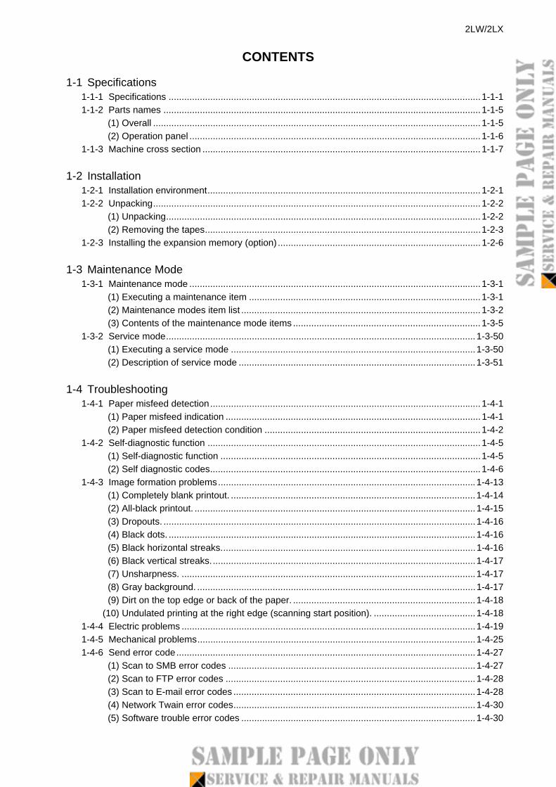
1-1-2 Parts names
(1) Overall
Figure 1-1-1
27
87
12
4
5
9
10
13
14 14
1823
20
22
21
24 2625
17
1615
3
6
11
12
1912
28
1. Platen (contact glass)2. Original size Indicator plate3. Operation panel4. Front upper cover5. Front cover6. USB Interface connector (front)7. Drum unit8. Lock lever9. Toner container
10. Top tray11. Paper length guide
12. Paper width guides13. Cassette14. Paper width guides (MP tray)15. MP (Multi-Purpose) tray16. MP tray extension17. Rear unit18. Main power switch19. Power cord connector20. USB Interface connector (rear)21. Network Interface connector22. Line connector (L1) *
23. Tel connector (T1) *24. DP top cover25. Original width guides26. Original table27. Original eject table28. Opening handle
* 4in1 model (with FAX) only
1-1-5

PARTS LISTPublished in April 2011
2MFPL070First Edition
FS-3040MFP+FS-3140MFP+

- 1 -
CONTENTS
FIG. 1 Covers ..................................................................... 2
FIG. 2 Frames 1 ................................................................. 4
FIG. 3 Frames 2 ................................................................. 6
FIG. 4 Paper Cassette ........................................................ 8
FIG. 5 Paper Feed Section 1 ............................................ 10
FIG. 6 Paper Feed Section 2 ............................................ 12
FIG. 7 Paper Feed Section 3 ............................................ 14
FIG. 8 Paper Feed Section 4 ............................................ 16
FIG. 9 Scanner Section .................................................... 18
FIG. 10 Image Formation Section ...................................... 20
FIG. 11 Developing Section ................................................ 22
FIG. 12 Fuser Section 1 ..................................................... 24
FIG. 13 Fuser Section 2 .................................................... 26
FIG. 14 Drive Section ......................................................... 28
FIG. 15 Exit Section ........................................................... 30
FIG. 16 Electrical Components ............................................32
FIG. 17 Operation Section ...................................................34
FIG. 18 Document Processor 1 ...........................................36
FIG. 19 Document Processor 2 ...........................................38
FIG. 20 Accessories ............................................................40
FIG. 21 Maintenance Kits ....................................................42
• INDEX .................................................................. 43

2MF/2MGFIG. 1 Covers
102
102102101
101
1
2
3
4
5
13
11
6
7
12
8
14
9
10
A
A
Top Related