


Languages
Pages
Legal

5/22/2012
Page 1
IN THIS WEBINAR:
• Summary of new features in v11.4
• Demonstration of some new features
• Available resources and support information
SDA Webinar
FEMAP 11.4 What’s New
David Cross, Ph.D.
Senior Aerospace Stress Engineer
Structural Design and Analysis
PRESENTED BY:
5/22/2012
Page 2STRUCTURES.AERO
FEMAP Direction
Maximize efficiency of FEA tasks
– Efficient creation of high fidelity FE models that accurately represent real-world engineering problems
– Intuitive interpretation of analysis results to improve the design and performance of engineered
products
Build upon strong FEMAP capabilities
– Geometry idealization and processing for FE models
– Powerful meshing, model creation and interactive editing
– In-depth support for industry standard solvers
– Flexible customization tools to streamline analysis processes
5/22/2012
Page 3STRUCTURES.AERO
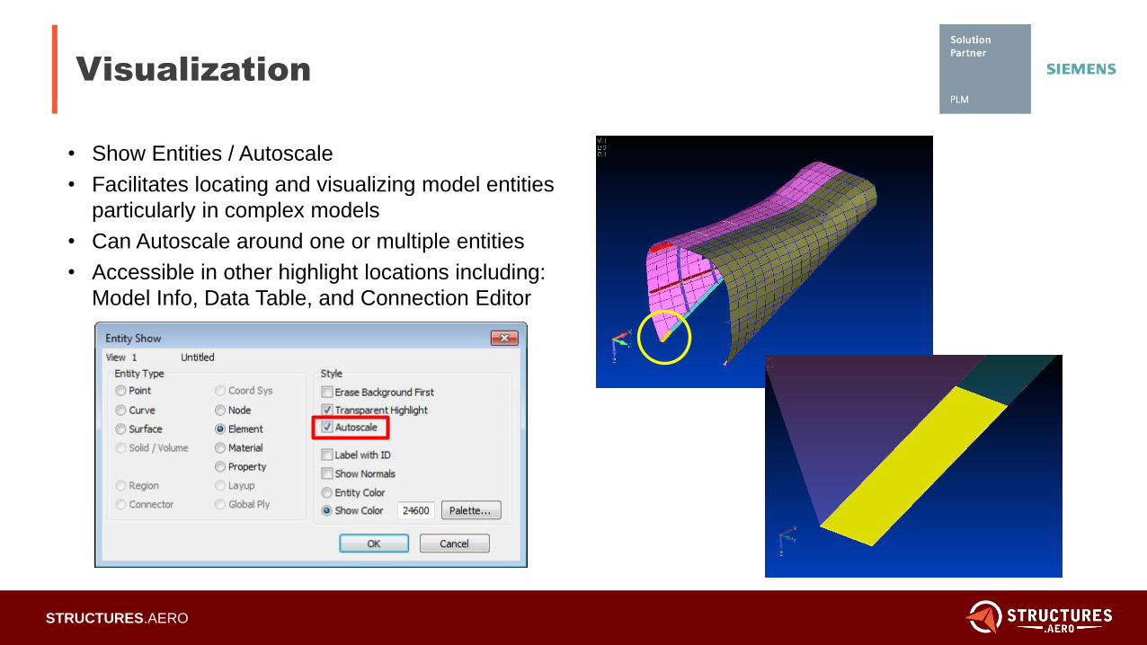
Visualization
• Show Entities / Autoscale
• Facilitates locating and visualizing model entities
particularly in complex models
• Can Autoscale around one or multiple entities
• Accessible in other highlight locations including:
Model Info, Data Table, and Connection Editor
5/22/2012
Page 4STRUCTURES.AERO
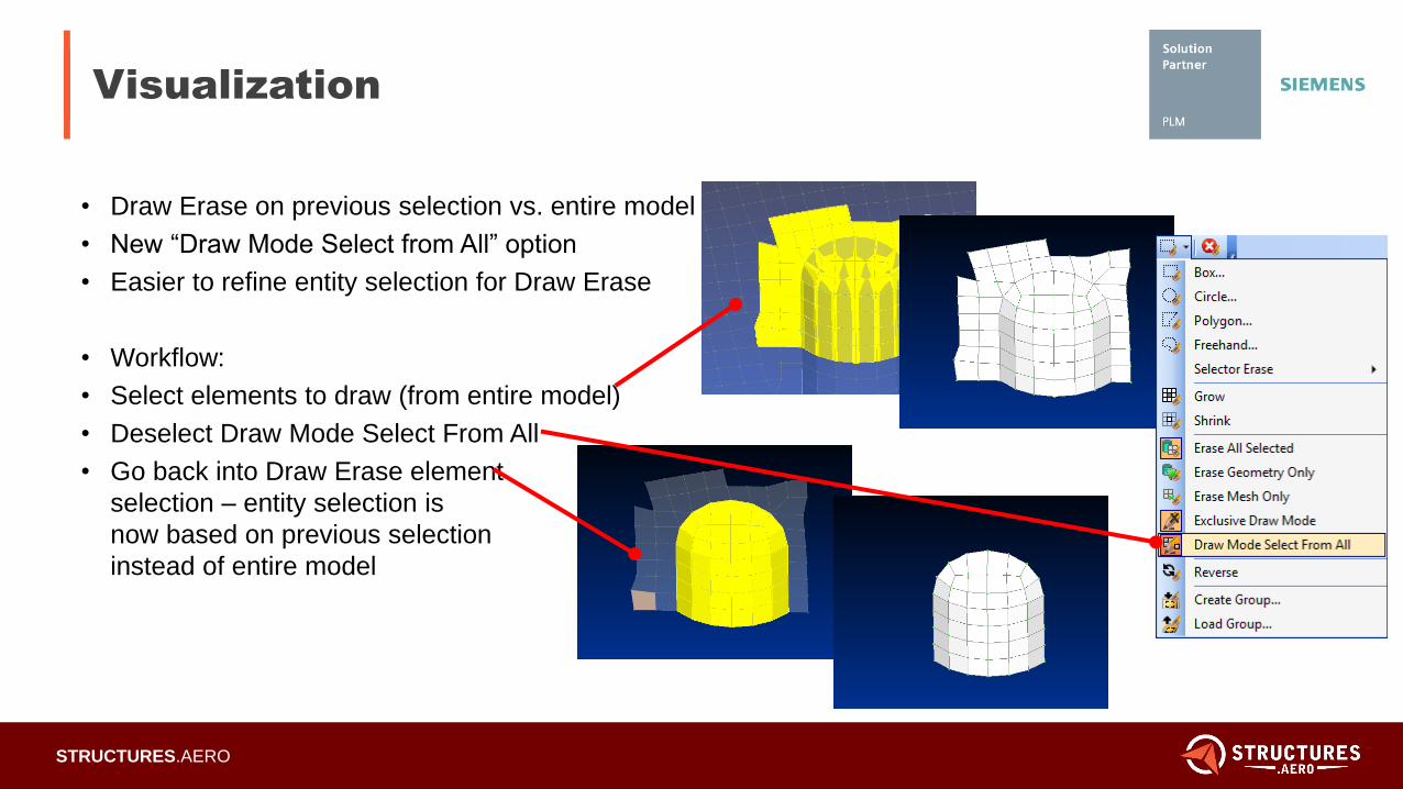
Visualization
• Draw Erase on previous selection vs. entire model
• New “Draw Mode Select from All” option
• Easier to refine entity selection for Draw Erase
• Workflow:
• Select elements to draw (from entire model)
• Deselect Draw Mode Select From All
• Go back into Draw Erase element
selection – entity selection is
now based on previous selection
instead of entire model
5/22/2012
Page 5STRUCTURES.AERO
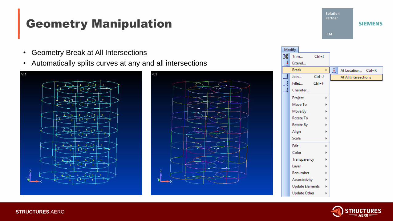
Geometry Manipulation
• Geometry Break at All Intersections
• Automatically splits curves at any and all intersections
5/22/2012
Page 6STRUCTURES.AERO
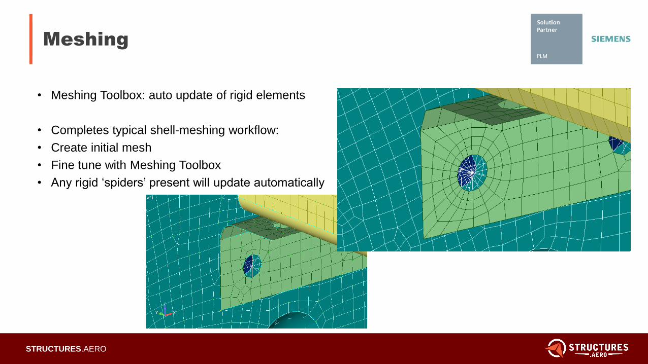
Meshing
• Meshing Toolbox: auto update of rigid elements
• Completes typical shell-meshing workflow:
• Create initial mesh
• Fine tune with Meshing Toolbox
• Any rigid ‘spiders’ present will update automatically
5/22/2012
Page 7STRUCTURES.AERO
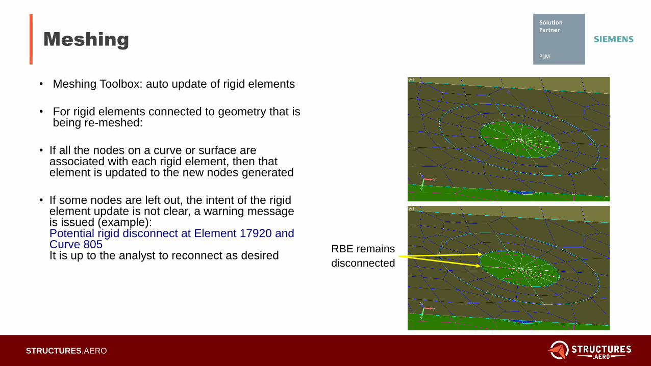
Meshing
• Meshing Toolbox: auto update of rigid elements
• For rigid elements connected to geometry that is being re-meshed:
• If all the nodes on a curve or surface are associated with each rigid element, then that element is updated to the new nodes generated
• If some nodes are left out, the intent of the rigid element update is not clear, a warning message is issued (example):Potential rigid disconnect at Element 17920 and Curve 805It is up to the analyst to reconnect as desired
RBE remains
disconnected
5/22/2012
Page 8STRUCTURES.AERO
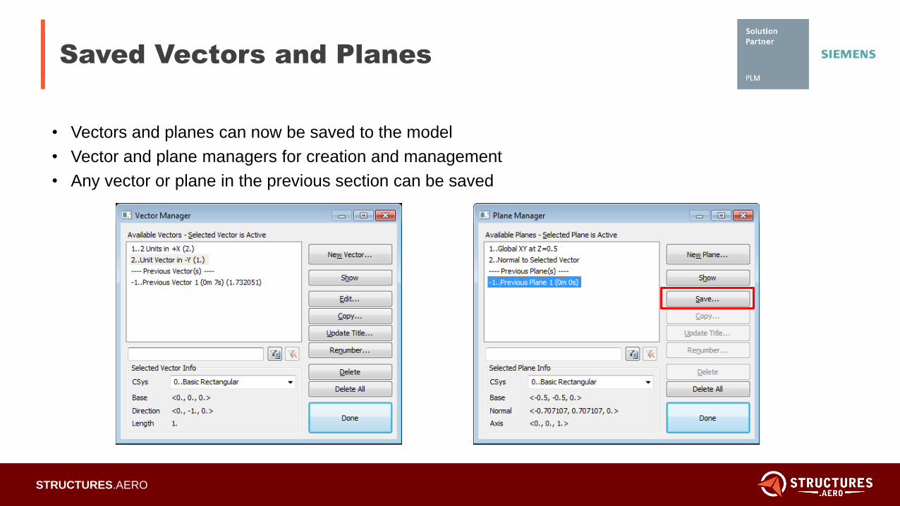
Saved Vectors and Planes
• Vectors and planes can now be saved to the model
• Vector and plane managers for creation and management
• Any vector or plane in the previous section can be saved
5/22/2012
Page 9STRUCTURES.AERO
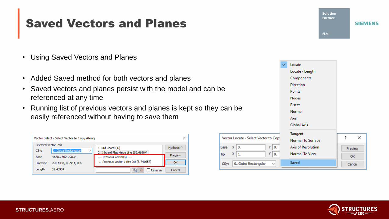
Saved Vectors and Planes
• Using Saved Vectors and Planes
• Added Saved method for both vectors and planes
• Saved vectors and planes persist with the model and can be
referenced at any time
• Running list of previous vectors and planes is kept so they can be
easily referenced without having to save them
5/22/2012
Page 10STRUCTURES.AERO
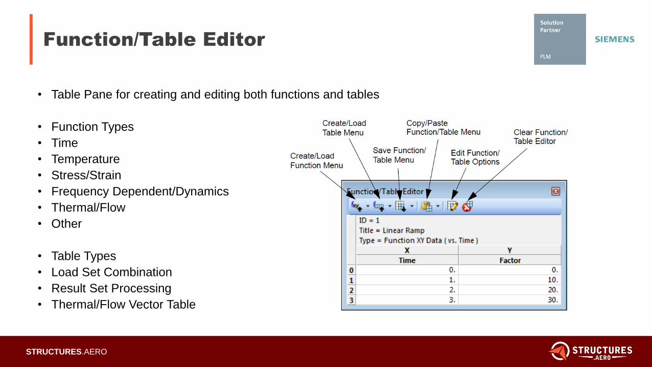
Function/Table Editor
• Table Pane for creating and editing both functions and tables
• Function Types
• Time
• Temperature
• Stress/Strain
• Frequency Dependent/Dynamics
• Thermal/Flow
• Other
• Table Types
• Load Set Combination
• Result Set Processing
• Thermal/Flow Vector Table
5/22/2012
Page 11STRUCTURES.AERO
Function/Table Editor
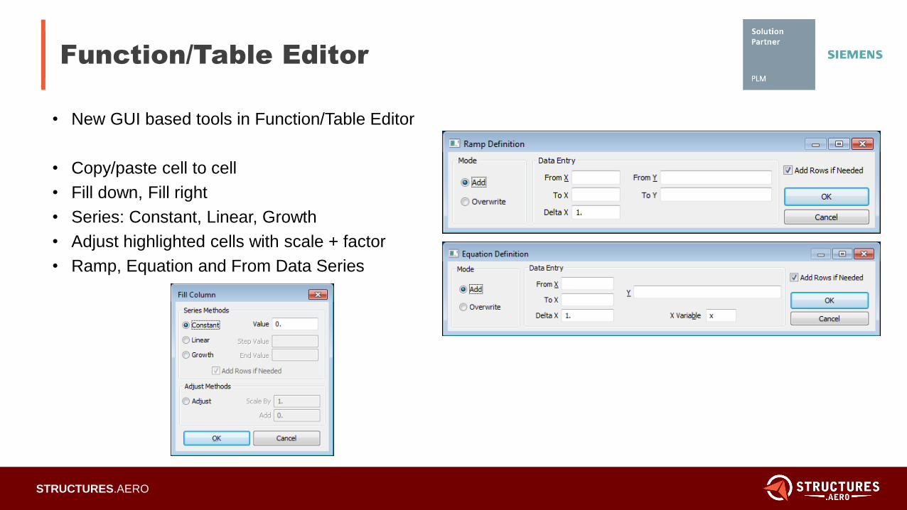
• New GUI based tools in Function/Table Editor
• Copy/paste cell to cell
• Fill down, Fill right
• Series: Constant, Linear, Growth
• Adjust highlighted cells with scale + factor
• Ramp, Equation and From Data Series
5/22/2012
Page 12STRUCTURES.AERO
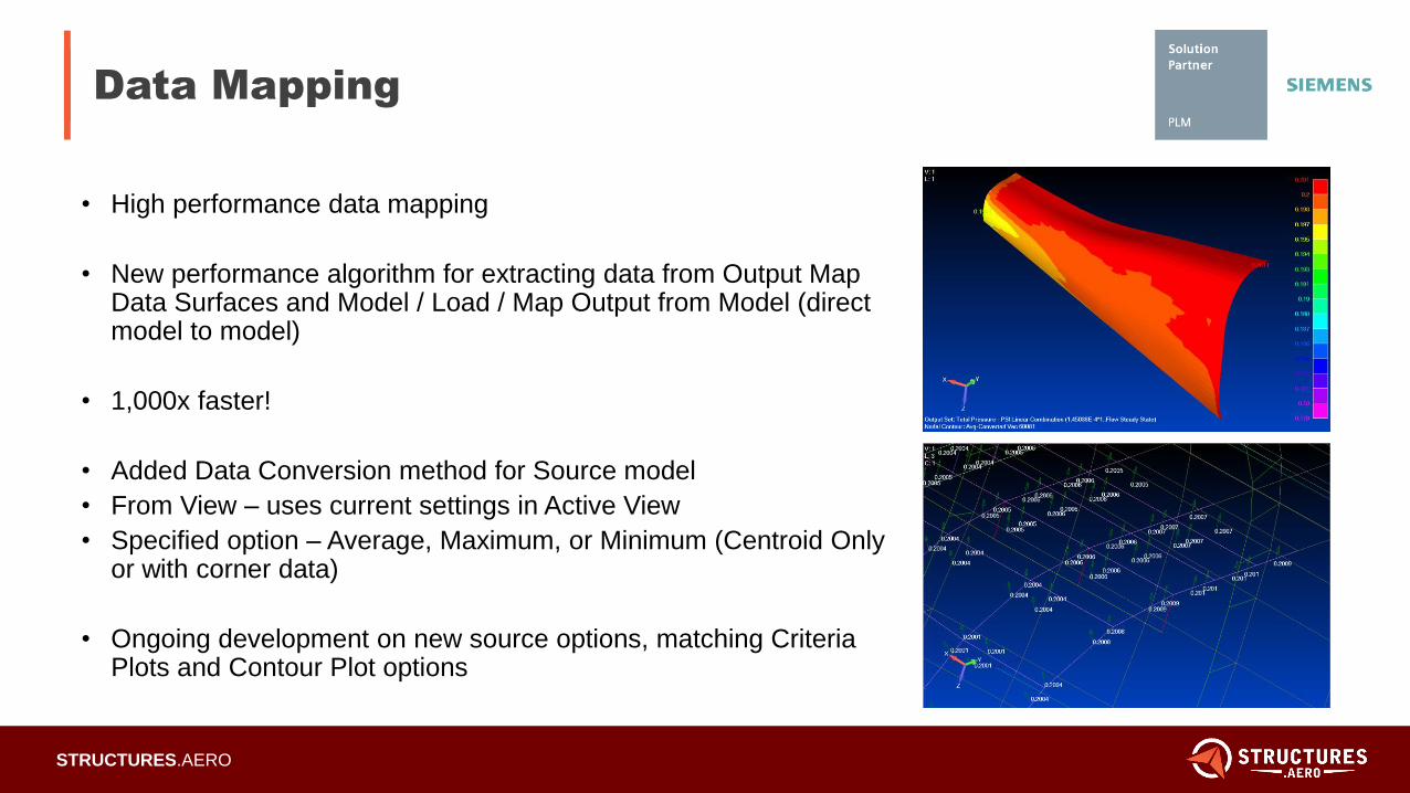
Data Mapping
• High performance data mapping
• New performance algorithm for extracting data from Output Map Data Surfaces and Model / Load / Map Output from Model (direct model to model)
• 1,000x faster!
• Added Data Conversion method for Source model
• From View – uses current settings in Active View
• Specified option – Average, Maximum, or Minimum (Centroid Only or with corner data)
• Ongoing development on new source options, matching Criteria Plots and Contour Plot options
5/22/2012
Page 13STRUCTURES.AERO
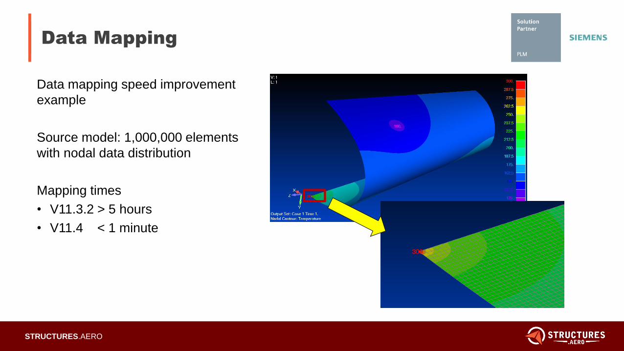
Data Mapping
Data mapping speed improvement
example
Source model: 1,000,000 elements
with nodal data distribution
Mapping times
• V11.3.2 > 5 hours
• V11.4 < 1 minute
5/22/2012
Page 14STRUCTURES.AERO
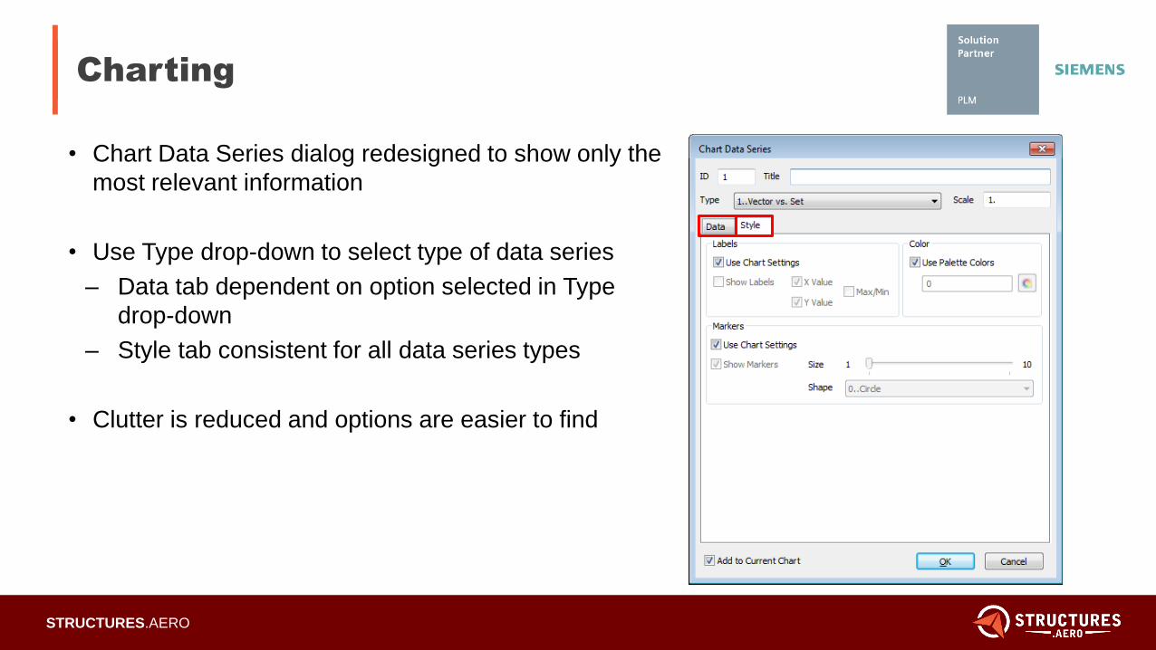
Charting
• Chart Data Series dialog redesigned to show only the
most relevant information
• Use Type drop-down to select type of data series
– Data tab dependent on option selected in Type
drop-down
– Style tab consistent for all data series types
• Clutter is reduced and options are easier to find
5/22/2012
Page 15STRUCTURES.AERO
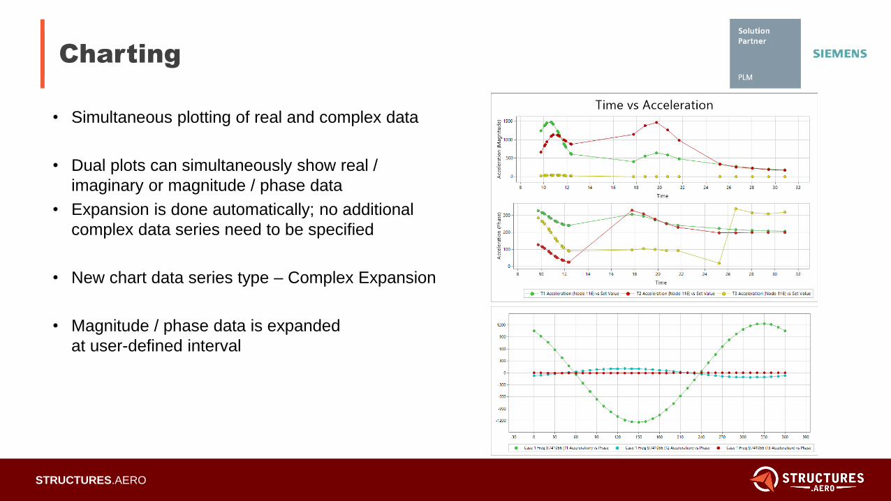
Charting
• Simultaneous plotting of real and complex data
• Dual plots can simultaneously show real /
imaginary or magnitude / phase data
• Expansion is done automatically; no additional
complex data series need to be specified
• New chart data series type – Complex Expansion
• Magnitude / phase data is expanded
at user-defined interval
5/22/2012
Page 16STRUCTURES.AERO
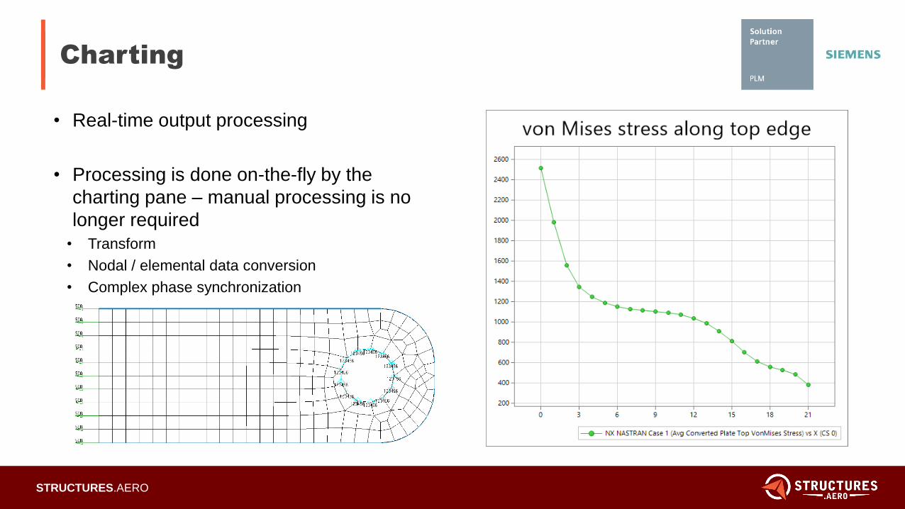
Charting
• Real-time output processing
• Processing is done on-the-fly by the
charting pane – manual processing is no
longer required
• Transform
• Nodal / elemental data conversion
• Complex phase synchronization
5/22/2012
Page 17STRUCTURES.AERO
Nastran Solver Support
• Nastran enhancements
• Param, POST, -2: reads nodal output in the basic coordinate system
• Strain Curvature output support
• Performance enhancements for reading large Nastran input files with many DMIG entries
• Read, keep and cycle CELAS1 entries in lieu of auto-converting to CELAS2 entries
• ZTOL entry support for Nastran radiation analysis
5/22/2012
Page 18STRUCTURES.AERO
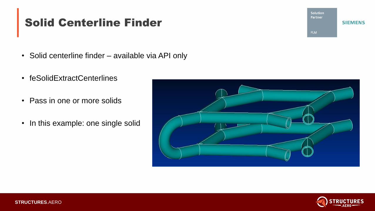
Solid Centerline Finder
• Solid centerline finder – available via API only
• feSolidExtractCenterlines
• Pass in one or more solids
• In this example: one single solid
5/22/2012
Page 19STRUCTURES.AERO
Solid Centerline Finder
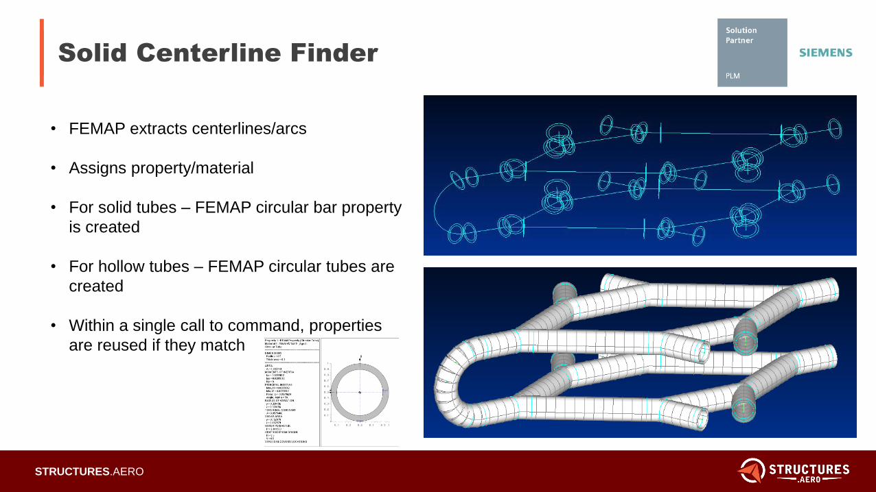
• FEMAP extracts centerlines/arcs
• Assigns property/material
• For solid tubes – FEMAP circular bar property
is created
• For hollow tubes – FEMAP circular tubes are
created
• Within a single call to command, properties
are reused if they match
5/22/2012
Page 20STRUCTURES.AERO
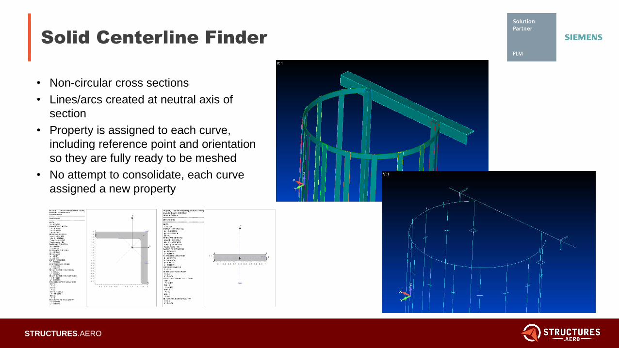
Solid Centerline Finder
• Non-circular cross sections
• Lines/arcs created at neutral axis of
section
• Property is assigned to each curve,
including reference point and orientation
so they are fully ready to be meshed
• No attempt to consolidate, each curve
assigned a new property
5/22/2012
Page 21STRUCTURES.AERO
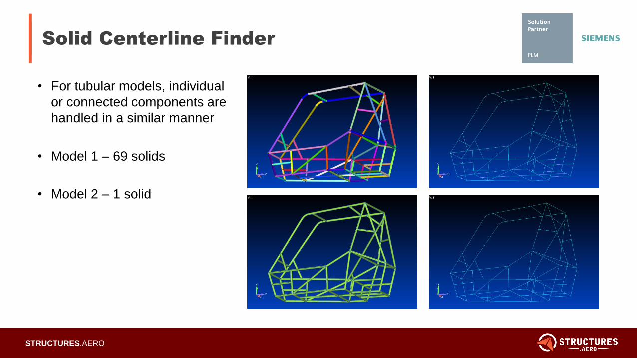
Solid Centerline Finder
• For tubular models, individual
or connected components are
handled in a similar manner
• Model 1 – 69 solids
• Model 2 – 1 solid
5/22/2012
Page 22STRUCTURES.AERO
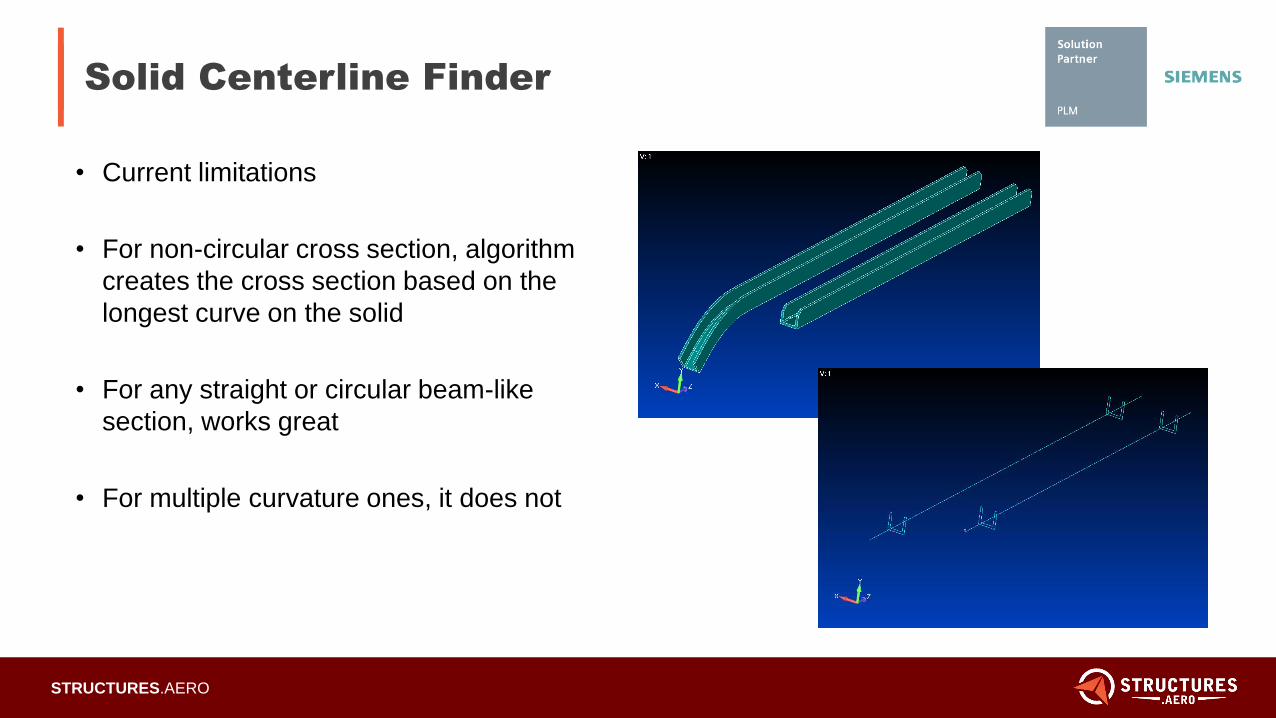
Solid Centerline Finder
• Current limitations
• For non-circular cross section, algorithm
creates the cross section based on the
longest curve on the solid
• For any straight or circular beam-like
section, works great
• For multiple curvature ones, it does not
5/22/2012
Page 23STRUCTURES.AERO
Additional Resources
• Download Femap 11.4:
http://download.industrysoftware.automation.siemens.com
• Femap Tutorial: https://structures.aero/femap-tutorial/
• Femap Webinars: https://structures.aero/webinar/#femap
• Femap Training: https://structures.aero/femap-training
5/22/2012
Page 24STRUCTURES.AERO
Structural Design and Analysis
(Structures.Aero)
Structural Analysis Software from the Engineers Who Use It

5/22/2012
Page 25STRUCTURES.AERO
For questions on the material covered
today, please contact David Cross.
For questions about pricing, or to see a
demo, please contact Marty Sivic.
Questions?
Marty SivicDirector of Sales
724-382-5290
David Cross, Ph.D.Senior Aerospace Stress Engineer
703-673-1125
Top Related