


Languages
Pages
Legal


Feedstock Physical Performance Modeling WBS 1.2.2.501
FCIC Kick-Off Meeting
Dec. 11, 2017
Tyler Westover, Hai Huang, Yidong Xia (INL)
Jonathan Stickel, Hariswaran Sitaraman (NREL)
George Fenske, Oyelayo Ajayi (ANL)
Carl Wassgren (Purdue University)
Bryan Ennis (E&G Associates)
Kerry Johanson (Material Flow Solutions)

The Fundamental Modeling Team
2
Tyler
Westover, Ph.D. Hai
Huang, Ph.D.
George Fenske, Ph.D. Oyelayo Ajayi, Ph.D.
Yidong
Xia, Ph.D.
Jonathan Stickel, Ph.D.
Mohammad Rahimi, PhD.
Hariswaran Sitaraman, PhD.
James Lischeske

Motivation 1. Developing reliable engineering design guides
– All current design guides use Mohr/Coulomb flow model, which is unreliable for biomass
– Will develop new guides based on advanced models
– Will propose rapid tests that industry can use near-term
2. Iterating process models / Identifying relationships – Modifying equipment after installation is expensive & slow;
modifying models is cheaper & faster
– Numerous examples: buildings, automobiles, pumps, etc.
– Properties vary in location, direction & scale (100’s of uncontrollable combinations)
– Variables cannot usually be physically isolated
– Physical tests have limited ability alone to determine relationships
– Cause & effect cannot always be physically determined
3. Transferring models between equipment & scale – Transfer key discoveries from lab to industry
Process Model
𝑚𝑔ℎ
2𝑐=2 sin 𝛼 cos(𝜑)
1 − cos(𝛼 − 𝜑)
1. Cohesion
2. Friction/shear strength
3. 3D Young’s moduli
4. Plastic hardening
5. Particle size and shape
6. Particle roughness
7. Moisture content
8. Bulk density
9. 3D Poisson ratios
10. Elastic recovery
11. Chemical composition
12. Particle durability
Potential dominant physical/mechanical properties
3

Objectives & Approach
Objective: Use mechanistic modeling to identify the causes of feed-handling failures and validate predictions to lead to improved process designs that enhance the reliability of industrial IBRs
3-Year Goal: Robust computational simulations and characterization methods to enable 50% improvement in operating reliability relative to base case, and reduced wear for coupled hopper/feed auger systems and compression screw augers at scales of 1 to 50 tonne/hr
History: This project began 1 year ago combining simulations and physical experiments and was annexed separately into FCIC
Technical Approach – Particle models (discrete element method, DEM)
– Reduced-order continuum models (averages over many particles)
• Plasticity/elasticity models for general flow & comminution
• Comp. fluid dynamics (CFD) for specific cases
• Analytical models for specific wear mechanisms
4

FCIC Connections
Fund. Mod.
Feed. Var.
+$$$
-$$$
Sys. Thru. Anal.
Proc. Int.
Proc. Cont&Opt.
• What properties • How to measure
• Materials • Properties
• What to model
• Scale factors • Variable relations • Mitigations
• Process characterization
• Variable relations • Design of sensors
• Process characterization
• Model down-selection
• Interpret/scale data • Mitigation strategies
5

Tasks and Connections
Task Name Inputs Outputs Specific driving
questions
Task 1: Baseline of current industry design practices Literature design methods
Effectiveness of current methods
What is the cause of current problems?
Task 2: Flow of elastoplastic bulk solid biomass
FV: Properties PI: Flow data
Flow models / functional parameter relationships:
FV, PI, PCO, SWA
What to measure? How to measure?
Which models work? How to interpret/use?
How to transfer or scale?
Task 3: Flow of highly compressed feedstocks (i.e. negligible elastic behavior) Same as #2 Same as #2: FV, PI, PCO, SWA Same as #2
Task 4: Mechanics of grinding (not currently funded) FV: Properties
Comminution …. (same as #2): FV, PI, PCO, SWA
Same as #2
Task 5: Adhesion, corrosion, erosion, and fatigue wear modeling (not currently funded)
FV: Properties PI: Wear data
Wear … (same as #2): FV, PI, PCO, SWA
Same as #2
6

Task 1: Baseline current design practices $160K: INL, NREL, ANL
• Objective:
– Understand limitations and failures of current industry design practices
– Example: Use of Mohr-Coulomb model to design bins, hoppers and feeders
– Will also look at
• Compression screw feeders
• Equipment wear
Predicted hopper opening size to cause flow vs. measured hopper opening size. Symbol size indicates moisture content from 10% (small) to 40% (large) (Hernandez, Westover, et al. , submitted for publication).
Ring shear tester. http://www.dietmar-
schulze.de/powtve.pdf
Motorized flow hopper at INL
7
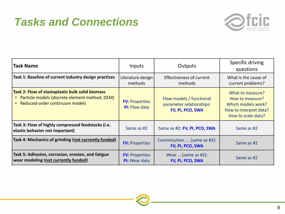
Tasks and Connections
Task Name Inputs Outputs Specific driving
questions
Task 1: Baseline of current industry design practices Literature design methods
Effectiveness of current methods
What is the cause of current problems?
Task 2: Flow of elastoplastic bulk solid biomass • Particle models (discrete element method, DEM) • Reduced-order continuum models FV: Properties
PI: Flow data
Flow models / functional parameter relationships:
FV, PI, PCO, SWA
What to measure? How to measure?
Which models work? How to interpret data?
How to scale data?
Task 3: Flow of highly compressed feedstocks (i.e. elastic behavior not important) Same as #2 Same as #2: FV, PI, PCO, SWA Same as #2
Task 4: Mechanics of grinding (not currently funded) FV: Properties
Comminution …. (same as #2): FV, PI, PCO, SWA
Same as #2
Task 5: Adhesion, corrosion, erosion, and fatigue wear modeling (not currently funded)
FV: Properties PI: Wear data
Wear … (same as #2): FV, PI, PCO, SWA
Same as #2
8
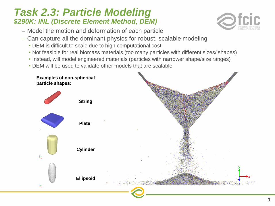
Task 2.3: Particle Modeling $290K: INL (Discrete Element Method, DEM)
– Model the motion and deformation of each particle
– Can capture all the dominant physics for robust, scalable modeling • DEM is difficult to scale due to high computational cost
• Not feasible for real biomass materials (too many particles with different sizes/ shapes)
• Instead, will model engineered materials (particles with narrower shape/size ranges)
• DEM will be used to validate other models that are scalable
9
String
Plate
Cylinder
Ellipsoid
Examples of non-spherical
particle shapes:

Task 2.3: Particle Modeling $290K: INL (Discrete Element Method, DEM)
– Modeling of material characterization
• Shear tests to measure friction and cohesion properties
– Can capture all the dominant physics for robust, scalable modeling • Will be used to validate continuum-models and guide characterization tests
10

Task 2.3: Particle Modeling $290K: INL (Discrete Element Method, DEM)
Model parameters
• 1 mm glass beads (ideal case)
• Includes sliding and rolling friction
11

Task 2.3: Particle Modeling $290K: INL (Discrete Element Method, DEM)
Ring shear tests of glass beads
• Physical shear test require >100 s
• Young’s Modulus = 1e7 Pa
• Fill depth = 20 cm
• Sliding friction: = 0.1 … 0.9
• Model time step ~ 1e-6 s, so ~10e9 simulation steps are needed
• Larger time steps can be used as assumed value of E decreases – Assuming E=1e7 is affordable
– Need to adjust other parameters to make simulations accurate
12
• Deformation (shear) strength strongly dependent upon sliding friction coefficient
• Model time step ~ 1e-6 s, so ~10e9 simulation steps are needed

Task 2.3: Particle Modeling $290K: INL (Discrete Element Method, DEM)
– Time sequence images of DEM simulation (wet glass beads flowing in a hopper).
– Important: material tends to flow and fall in packets (episodic flow)
– Experiments show biomass flow is also episodic
– DEM can accurately capture this effect, which is very difficult for continuum models
13
5E-03% 5E-02% 1E-01%
0
10
20
30
40
50
60
70
80
90
100
0 2 4 6 8 10 12 14
Total lost particles (%)
b
5.0E-03%
0
10
20
30
40
50
60
70
80
90
100
0 2 4 6 8 10 12 14
Total lost particles (%)
b
5.0E-02%
0
10
20
30
40
50
60
70
80
90
100
0 2 4 6 8 10 12 14
Total lost particles (%)
b
1.0E-01%
Effects of moister content on hoper flow:

Task 2.1: Continuum ( ) Modeling $560K: INL, NREL
• Assumes that particles are small and behave as a continuum – Does not have direct particle effects
because models average over particles
• Simplest powder flow model is the Mohr-Coulomb Model (MCM) – Used to develop all design guides for
handling particulate materials
– Basis of ~all continuum flow models
– Assumes perfect plasticity/elasticity
– Works very poorly for biomass
• Requires 5 parameters – Cohesion, c
– Internal friction angle, 𝝋
– Young’s modulus, E
– Poisson’s ratio, 𝛖
– Dilation angle, 𝛄
– c, 𝝋 have similar behavior as for rigid bodies
m·g
Ffric
N
Fshear = c・ A + μ・ N
c (cohesion)
𝝉(𝒔𝒉𝒆𝒂𝒓𝒔𝒕𝒓𝒆𝒔𝒔)
𝝋= tan−1(μ)
𝝈(𝒄𝒐𝒎𝒑𝒓𝒆𝒔𝒔𝒊𝒗𝒆𝒔𝒕𝒓𝒆𝒔𝒔)
α
‘Ave
rag
e s
he
ar
str
es
s’
‘Average compressive stress’
Real material with changing properties
Mohr-
Coulomb model
Reduced-order
14

Continuum (Reduced-order) Modeling $560K: INL, NREL
0.0
0.1
0.2
0.3
0.4
0.5
0.6
0.7
-15 -10 -5 0 5 10 15V
elo
cit
y (
m/s
)
Position along outlet (mm)
16 elements, 0.2 m hopper
16 elements, 0.52 m hopper
24 elements, 0.52 m hopper
• Brick, partitioned mesh
• Mesh refinement study used 16, 24, and 32 elements across the hopper outlet
• ‘Simple hopper flow’ – Does not account for episodic flow at outlet
– Eulerian approach (mesh does not deform)
15

Continuum (Reduced-order) Modeling $560K: INL, NREL
• Model adjusted to match flow of 3 mm PFR
– c = 10 Pa; φ = 40°
– Precision of shear tester is ~100 Pa
– Need better method to measure cohesion, c
Ring shear tester. http://www.dietmar-
schulze.de/powtve.pdf
Shear characterization pine forest residue
(PFR) and corn stover (CS) materials
16

Continuum (Reduced-order) Modeling $560K: INL, NREL
• More advanced models are needed to address challenging issues – Non-ideal elastic and plastic behavior
– Creep
– Anisotropy
– Hysteresis
– Damping
– Mesh deformation & ‘packet, episodic’ flow
• A Variety of models are available but all will require modification – Modified Drucker-Prager Cap (DPC) model
– Non-local granular fluidity (NLGF) model
– Smoothed-Particle Hydrodynamics (SPH) model
Adaptive mesh: remeshes
after each time step to reduce element distortion
17

Tasks and Connections
Task Name Inputs Outputs Specific driving
questions
Task 1: Baseline of current industry design practices Literature design methods
Effectiveness of current methods
What is the cause of current problems?
Task 2: Flow of elastoplastic bulk solid biomass • Particle models (discrete element method, DEM) • Reduced-order continuum models FV: Properties
PI: Flow data
Flow models / functional parameter relationships:
FV, PI, PCO, SWA
What to measure? How to measure?
Which models work? How to interpret data?
How to scale data?
Task 3: Flow of highly compressed feedstocks (i.e. elastic behavior not important) Same as #2 Same as #2: FV, PI, PCO, SWA Same as #2
Task 4: Mechanics of grinding (not currently funded) FV: Properties
Comminution …. (same as #2): FV, PI, PCO, SWA
Same as #2
Task 5: Adhesion, corrosion, erosion, and fatigue wear modeling (not currently funded)
FV: Properties PI: Wear data
Wear … (same as #2): FV, PI, PCO, SWA
Same as #2
18

Task 3.1 CFD Modeling ( ) Compression Screw Feeder
Compression-screw
Feeder
To Pretreatment or
Pyrolysis Reactor
Feed
Hopper
High
pressure
Challenge: Compression-screw feeding
of biomass feedstock
• Direct feeding operation into
pretreatment and pyrolysis reactors
(>50 kPa)
• Prone to upsets (plugging, blowback)
• Sensitive to material properties
• Upsets often cause shutdown of
downstream operations
Approach: Predict feedstock properties and
operating conditions for reliable operation
• Moist feedstock particles are compressed
to form a single deforming material
• CFD models will represent the material as
a single continuum with non-Newtonian
rheology
• Mixture model to represent varying liquid
and air content that affect the rheology
• OpenFOAM CFD software will be used to
perform the simulations on NREL’s HPC
19

Task 5 Wear Modeling
• Based on indentation plasticity and
micro-fracture from kinetic energy.
Corn stover isconsidered a
composite material with a abrasive
particles in a soft matrix
• Will model hammer milling and
sliding/conveying.
• Will require material
characterization data, such as
composition, properties and
characteristics of ash and other
contaminant particles.
Goal – develop analytic model of wear
(abrasive) with capability to predict
component/material wear based on biomass
properties and equipment parameters
Wear Rate (m/s)= 𝑾𝒆𝒂𝒓𝑪𝒐𝒆𝒇𝒇 × 𝑷𝑽
Wear Coefficient considerations
– Basic form – dependent on mechanism
(abrasive, adhesive, fatigue, corrosion ….)
– Dependent on elastic properties of
ash/debris and stover (moisture)
– Ash composition – properties, sizes, etc.,
PV considerations – contact pressure applied
to ash/debris
– Load and speed – operational parameters
– Load sharing between stover and ash
– Effect of moisture (lubricant)
20

Summary
Outcomes: Model framework and methods to measure material properties that will enable predicting the flow behavior of biomass over a wide range of industrial operations at any scale
1. Reliable engineering design guides based upon advanced rheological models (not Mohr-Coulomb)
2. Rapid flow tests for short-term industrial use
3. Detailed, robust particle models to understand mechanics
4. Reduced-order continuum models to accelerate process iteration and control and that can provide scaling between facilities and scales
Process Model
𝑚𝑔ℎ
2𝑐=2 sin 𝛼 cos(𝜑)
1 − cos(𝛼 − 𝜑)
1. Cohesion
2. Friction/shear strength
3. 3D Young’s moduli
4. Plastic hardening
5. Particle size and shape
6. Particle roughness
7. Moisture content
8. Bulk density
9. 3D Poisson ratios
10. Elastic recovery
11. Chemical composition
12. Particle durability
Potential dominant physical/mechanical properties
21