


Languages
Pages
Legal


FEED FORWARD LINEAR QUADRATIC CONTROLLER
DESIGN FOR AN INDUSTRIAL ELECTRO HYDRAULIC
ACTUATOR SYSTEM WITH SERVO VALVE
J. Micheal, M.F. Rahmat*, N. Abdul Wahab and W.K. Lai
Department of Control and Instrumentation Engineering, Faculty of Electrical Engineering
Universiti Teknologi Malaysia, 81310 Skudai, Johor, Malaysia
Emails: [email protected], [email protected], [email protected],
*Correspondent author: M.F. Rahmat, [email protected]
Submitted: Sep. 25, 2012 Accepted: Dec. 15, 2012 Published: Feb. 20, 2013
Abstract- Electro-hydraulic servo actuator (EHA) system consists of several dynamic parts which are
widely used in motion control application. These dynamic parts need to be controlled to determine
direction of the motion. In this research paper, system identification technique is used for system
modeling and the model of the system is estimated by using parameter estimation technique. This
process started with collection of input and output data from experimental procedure. The data
collected is used for model estimation and Auto Regressive with eXogeneous input (ARX) model is
chosen as model structure of the system. Based on the input and output data of the system, best fit
criterion and correlation analysis of the residual is analyzed to determine the adequate model to
represent the EHA system. Once the model is obtained, discrete PID and feed forward plus Linear
INTERNATIONAL JOURNAL ON SMART SENSING AND INTELLIGENT SYSTEMS VOL. 6, NO. 1, FEBRUARY 2013
154

Quadratic Regulator (LQR) controller is developed to improve the performance and position tracking
performance of EHA system. In order to verify these controllers, it is applied to the real time system
and the performance of the system is monitored. The result obtained shows that the output of the
system in simulation mode and experimental works is almost similar for both controllers. The output of
the system also tracked the input given successfully. Finally, by comparing the best tuning output from
these two different controllers, feed forward plus LQR controller proved to give a better output
performance than the classical discrete PID controller by minimize the phase lag and reduce
disturbance effect in the system.
Index terms: Electro-hydraulic system, System identification, ARX model, PID controller, LQR controller
I. INTRODUCTION
It is often necessary to design fast and accurate controllers for plants in which system parameters
substantially change, or for plants which operate under large external disturbances. To name a
few among such plants, there are robot manipulators picking and playing payloads, indexing
systems of flexible forging machine which rotate inertia changing work pieces and flight control
systems under large wind resistance. In order to satisfactorily control such plants, it is necessary
to have an actuator that can supply sufficient instantaneous torque demanded for fast control
actions and a control law which enables fast and accurate control under two factors which are
internal parameter variations and external disturbances. For an actuator required for control
actions, an Electro-hydraulic actuator (EHA) system appears a reasonable choice. Figure 1 shows
the actual model of an EHA system.
Figure 1. Model of EHA System
J. Micheal, M.F. Rahmat, N. Abdul Wahab and W.K. Lai, Feed Forward Linear Quadratic Controller Design For an Industrial Electro Hydraulic Actuator System with Servo Valve
155

EHA system converts electrical signal to hydraulic power[1]. It has become one of the most
important actuators in the recent decades. It offers many advantages such as good capability in
positioning, fast and smooth response characteristics and high power density. Due to its
capability in positioning, it has given a significant impact in modern equipment for position
control applications. Its applications in position control can be found in production assembly
lines, robotics, aircraft equipment and in industrial process.
However, EHA system is a complicated system which suffers from uncertainties, nonlinearities
and disturbances. These inconveniences may lead to degradation of control performance in force,
pressure or position tracking of EHA system[2]. Position tracking performance of EHA can be
assured when its robustness and tracking accuracy are guaranteed. The robustness and tracking
accuracy can be ensured when nonlinear behaviours, uncertainties and disturbances in the EHA
system are compensated.
Therefore, this project is important in that it will use two different controllers which are PID and
LQR in order to improve the position tracking of EHA system. Hence the accuracy and best
fittings between the two controllers will be compared. It expects to contribute a significant
impact in the control of modern equipment positioning applications.
II. BACKGROUND STUDY
a. Typical positioned EHA system
Hydraulic motion drives are widely used in several areas of industry, especially in application
that require high forces and torque. Figure 2 shows the block diagram of a typical position
controlled hydraulic system consist of a power supply, flow control valve, linear actuator,
displacement transducer, and electronic servo-controller. The servo controller compares the
signal from the feedback displacement to drive the flow control valve. The control valve adjusts
the flow of pressurized oil to move the actuator until the desired position is attained; a condition
indicate by the error signal falling to zero. A force controlled hydraulic system operates in
similar way, except the oil flow is adjusted to achieve output force measured by a suitable
transducer. While typical hydraulic system has relatively simple mechanical components, they
INTERNATIONAL JOURNAL ON SMART SENSING AND INTELLIGENT SYSTEMS VOL. 6, NO. 1, FEBRUARY 2013
156
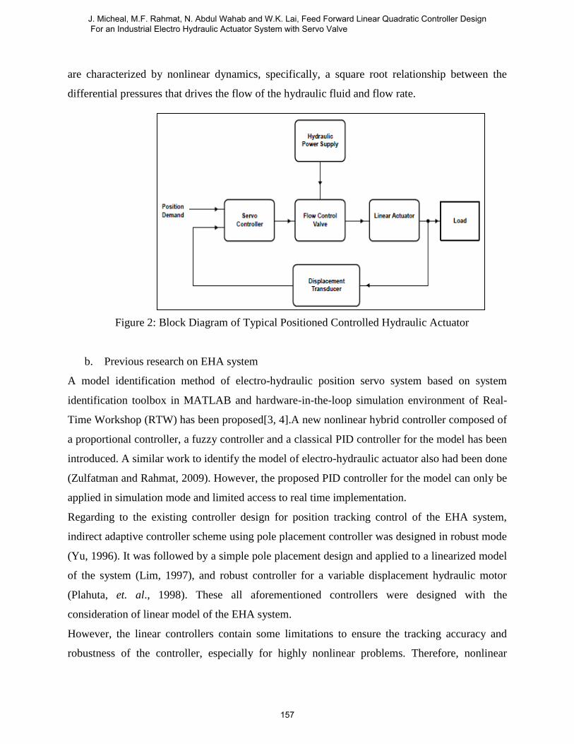
are characterized by nonlinear dynamics, specifically, a square root relationship between the
differential pressures that drives the flow of the hydraulic fluid and flow rate.
Figure 2: Block Diagram of Typical Positioned Controlled Hydraulic Actuator
b. Previous research on EHA system
A model identification method of electro-hydraulic position servo system based on system
identification toolbox in MATLAB and hardware-in-the-loop simulation environment of Real-
Time Workshop (RTW) has been proposed[3, 4].A new nonlinear hybrid controller composed of
a proportional controller, a fuzzy controller and a classical PID controller for the model has been
introduced. A similar work to identify the model of electro-hydraulic actuator also had been done
(Zulfatman and Rahmat, 2009). However, the proposed PID controller for the model can only be
applied in simulation mode and limited access to real time implementation.
Regarding to the existing controller design for position tracking control of the EHA system,
indirect adaptive controller scheme using pole placement controller was designed in robust mode
(Yu, 1996). It was followed by a simple pole placement design and applied to a linearized model
of the system (Lim, 1997), and robust controller for a variable displacement hydraulic motor
(Plahuta, et. al., 1998). These all aforementioned controllers were designed with the
consideration of linear model of the EHA system.
However, the linear controllers contain some limitations to ensure the tracking accuracy and
robustness of the controller, especially for highly nonlinear problems. Therefore, nonlinear
J. Micheal, M.F. Rahmat, N. Abdul Wahab and W.K. Lai, Feed Forward Linear Quadratic Controller Design For an Industrial Electro Hydraulic Actuator System with Servo Valve
157

robust controllers which ensure the stability and robustness of the system were developed due to
their main advantage in manipulating nonlinearities in the system (Sohl and Bobrow, 1999),
combined with adaptive features for double-rod actuator (Yao, et. al., 2001) and single-rod
actuator (Yao, et. al., 2001), trajectory-based (Loukianov, et. al., 2009). These control designs
were completing with two powerful robust controllers based-Lyapunov function. They were
Backstepping Mcontroller and Variable Structure Control (VSC). They commonly present in
their combination with adaptive, fuzzy logic or neural networks. Backstepping controllers which
constitute a powerful control strategy for handling the nonlinearities of EHA system were
introduced by (Sirouspour and Salcudean, 2001), (Kadissi, et. al., 2007), (Zeng and Sepehri,
2008), and (Guan and Pan, 2008).
Also, there were number of efforts which employed by using artificial intelligent techniques such
as ANN (Jianjun, et. al., 2008), and fuzzy control (Kalyoncu and Haydim, 2009). Other efforts
were carried out by combining the merits of fuzzy and conventional controllers in (Shao, et. al.,
2005) and (Kyoung, et. al., 2007).
c. Modeling of EHA system
A mathematical modeling model of EHA consists of the dynamics of the system disturbed by an
external load and the dynamic of a servo valve. The linear differential equations that describe the
actuator valve dynamics are given by,
)1()()()(1
)( tFtbtAPm
t LpL
)2()()()(4
tAtPKtxKV
P pLffL
where,
vp = piston velocity
PL = hydraulic pressure
FL = external load disturbance
xv = spool valve displacement
A = piston surface area
m = mass of the load
INTERNATIONAL JOURNAL ON SMART SENSING AND INTELLIGENT SYSTEMS VOL. 6, NO. 1, FEBRUARY 2013
158

β = effective bulk modulus
b = viscous damping coefficient
V = total volume of hydraulic oil in the piston chamber and the connecting lines
For zero initial conditions, the Laplace Transform of the equation (1) and (2) produced the
following input-output relation,
)3()()()()( sFsHXsHsU LLP
where,
)4(4)4)((
4)(
2bAKVsbms
AKsH
f
f
)5(4)4)((
4)(
2bAKVsbms
VsAKsH
f
f
L
The transfer function of solenoid can be approximated by the servo valve spool position gain
denoted by kv. Thus, input- output relation (3) can be written as
)6()()()()( sFsHsVksHU LLinvp
where,
Vin(s) = Laplace transform of the control voltage vin(t)
Using the equation (1) and (2), linear system with uncertain structure is derived in state space
form as,
)7()()()()()()( tFDtvqBtxqAtxdt
dLoinoo
)()( txCty o
where,
J. Micheal, M.F. Rahmat, N. Abdul Wahab and W.K. Lai, Feed Forward Linear Quadratic Controller Design For an Industrial Electro Hydraulic Actuator System with Servo Valve
159

0
1
)(
01)(
40
)(
44)(
)(
)()(
21
211
mqD
qC
V
kqqqB
V
V
Aqm
A
m
b
qA
tP
ttx
o
o
vo
o
L
p
Thus, the mathematical model of EHA system is fully cleared and established.
III. METHODOLOGY
System identification is a process of formulating mathematical model of systems using
measurement data [5].The term identification was first introduced by Zadeh [6], referring to the
problem of determining the input-output relationships of a black box or modeling based on
experimental data sets. Model of the system is needed as the prediction of system’s behavior and
aid in controller design. Stimulus signal is the signal used to excite the system so that the
characteristics of system can be realised. Thus, the signal has to be rich in frequency and
amplitude which excite every operation region of the system.
Good stimulus signal can assure a more accurate model. Linearization process during data taking
process is Important, as EHA system is nonlinear. Without linearization, the linear estimation of
the model is hard to achieve. The linearization process is done be adding an offset to the stimulus
signal. After the input and output data is linearized, linear model estimation method can be
applied. A linear model is used to estimate a nonlinear model as the EHA system. Linear model
is used as it is the simplest, discrete time model that can represent the relationship between u(t)
and y(t). Linear model is chosen over nonlinear model as linear model is much simpler than
nonlinear model, while at the same time, can represent the behaviour of the real system with high
INTERNATIONAL JOURNAL ON SMART SENSING AND INTELLIGENT SYSTEMS VOL. 6, NO. 1, FEBRUARY 2013
160
precision. Thus, ARX model which is the simplest and most popular model is chosen to estimate
the EHA system.
IV. EXPERIMENTAL SETUP
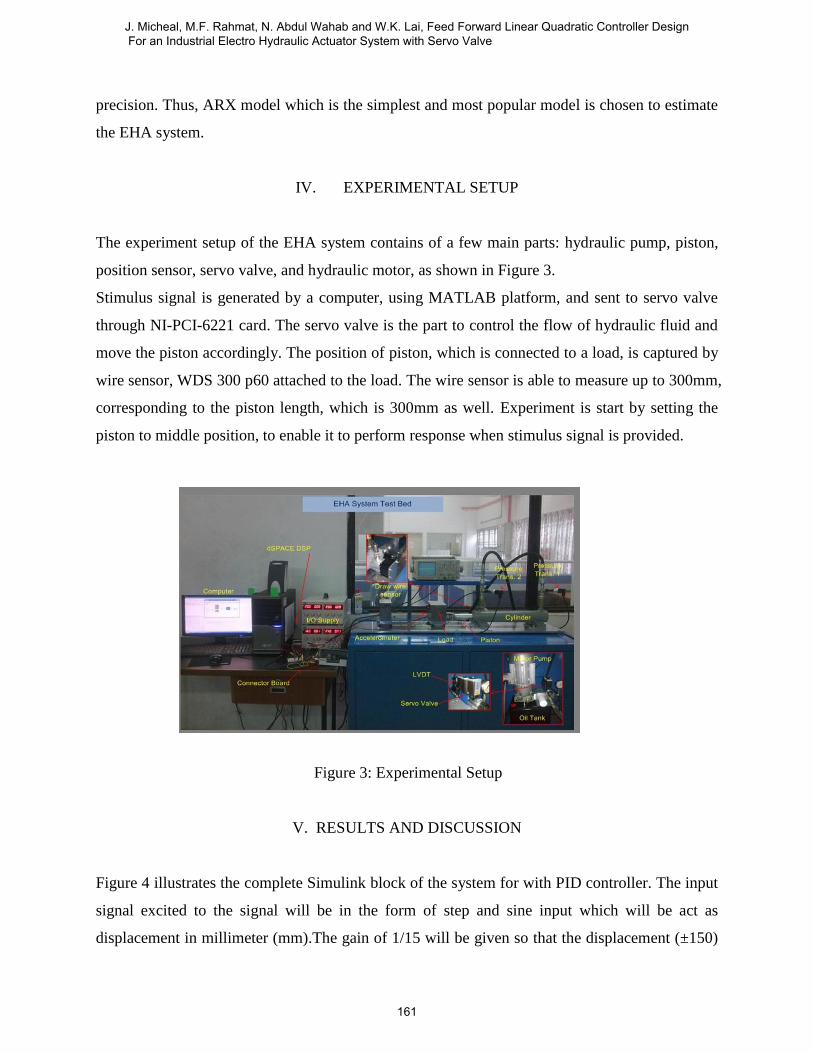
The experiment setup of the EHA system contains of a few main parts: hydraulic pump, piston,
position sensor, servo valve, and hydraulic motor, as shown in Figure 3.
Stimulus signal is generated by a computer, using MATLAB platform, and sent to servo valve
through NI-PCI-6221 card. The servo valve is the part to control the flow of hydraulic fluid and
move the piston accordingly. The position of piston, which is connected to a load, is captured by
wire sensor, WDS 300 p60 attached to the load. The wire sensor is able to measure up to 300mm,
corresponding to the piston length, which is 300mm as well. Experiment is start by setting the
piston to middle position, to enable it to perform response when stimulus signal is provided.
Figure 3: Experimental Setup
V. RESULTS AND DISCUSSION
Figure 4 illustrates the complete Simulink block of the system for with PID controller. The input
signal excited to the signal will be in the form of step and sine input which will be act as
displacement in millimeter (mm).The gain of 1/15 will be given so that the displacement (±150)
J. Micheal, M.F. Rahmat, N. Abdul Wahab and W.K. Lai, Feed Forward Linear Quadratic Controller Design For an Industrial Electro Hydraulic Actuator System with Servo Valve
161

will be converted to voltage (±10) for the signal to enter the system. The feedback loop will loop
back and compensate the error signal and PID controller will be compensated so that system will
produce the best performance. Block diagram of LQR plus feed forward controller is shown in
Figure 5. Based on the figure, the LQR controller acts as a feedback control which permits the
system’s output to follow the desired trajectory while feed forward controller is introduced to
reduce the phase lag due to feedback control problem.
Figure 4: PID Controller Simulation Block
Figure 5: LQR plus Feed Forward Controller Simulation Block
a. PID controller via simulation
Response of PID controller with step and sine input in simulation are shown in Figure 7 and 8. .
The critical gain for the model attained is Kc = 10.35 with critical period, Tc = 3.632. From
calculation based on Ziegler Nichols tuning method and trial and error method, the PID
In1Out1
state space
Switch2
Switch1
Switch
Sensor Output
Displacement (m)
Scope5
Scope3
Saturation
PID
PID
Klqr* u
LQR1
r(k)
r(k+3)
Input
Trajectory
Input Disp
Hydraulic System
In1 Out1
Feedforward
LQR
Displacement
Tracking
Reference
INTERNATIONAL JOURNAL ON SMART SENSING AND INTELLIGENT SYSTEMS VOL. 6, NO. 1, FEBRUARY 2013
162

controller’s tuning parameters are obtained. The parameters are Kp = 6.20968, Ki = 3.4198 and
Kd = 2.19014. The simulation is simulated in discrete form with 0.05second sampling time and
the input reference is set to 50mm as the desired position.
Figure 6: Response of PID Controller with Step Input (Simulation)
Figure 7: Response of PID Controller with Sine Input (Simulation)
Based on Figures 6 and 7, by adding PID controller in the forward path of the system, the output
response of the system with step and sine input are improved. The output of the system has
successfully tracked the input given with very small steady state error.
J. Micheal, M.F. Rahmat, N. Abdul Wahab and W.K. Lai, Feed Forward Linear Quadratic Controller Design For an Industrial Electro Hydraulic Actuator System with Servo Valve
163
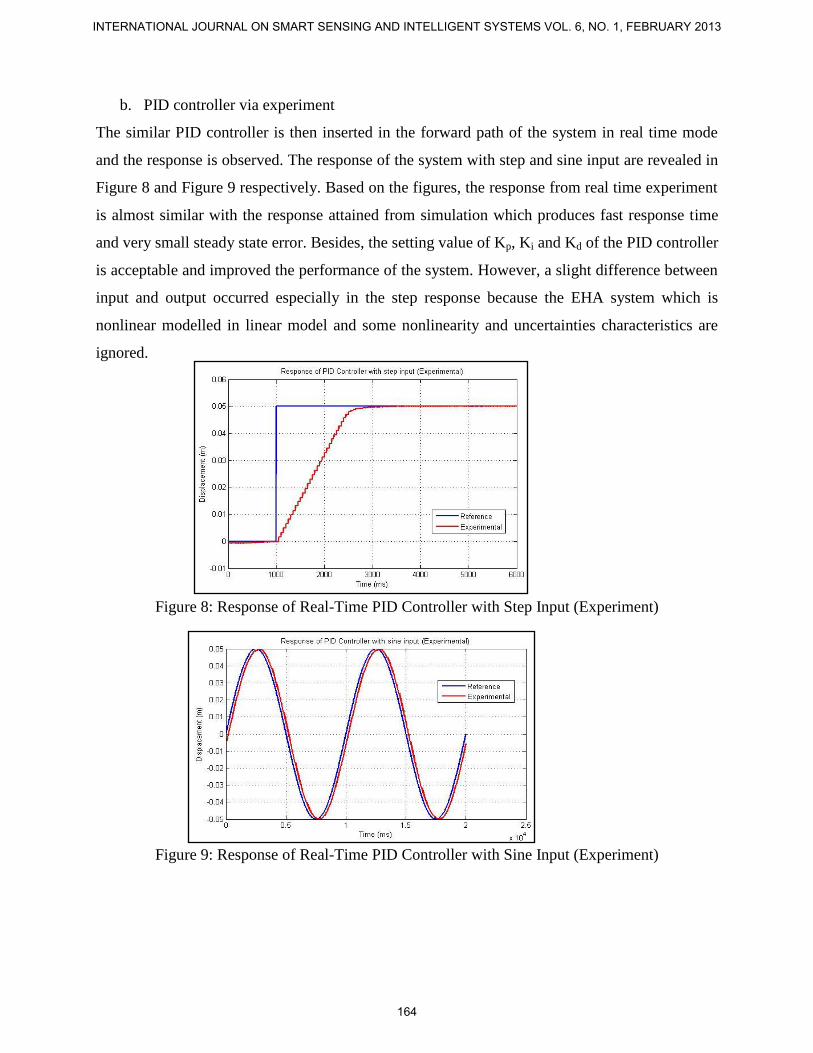
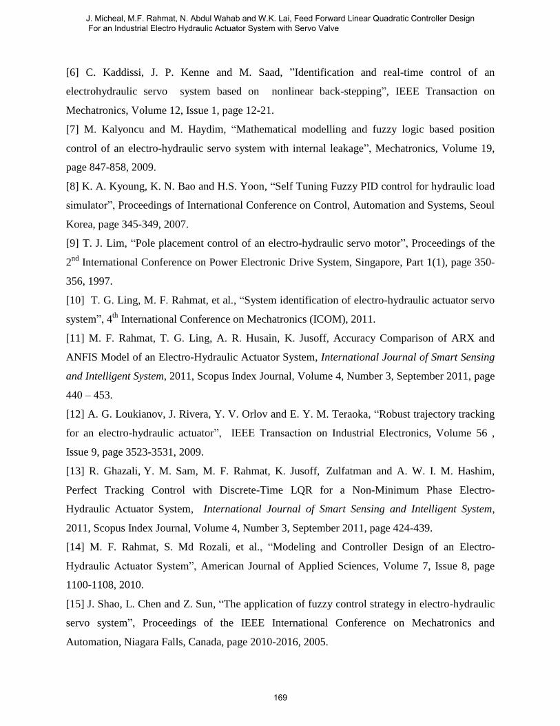
b. PID controller via experiment
The similar PID controller is then inserted in the forward path of the system in real time mode
and the response is observed. The response of the system with step and sine input are revealed in
Figure 8 and Figure 9 respectively. Based on the figures, the response from real time experiment
is almost similar with the response attained from simulation which produces fast response time
and very small steady state error. Besides, the setting value of Kp, Ki and Kd of the PID controller
is acceptable and improved the performance of the system. However, a slight difference between
input and output occurred especially in the step response because the EHA system which is
nonlinear modelled in linear model and some nonlinearity and uncertainties characteristics are
ignored.
Figure 8: Response of Real-Time PID Controller with Step Input (Experiment)
Figure 9: Response of Real-Time PID Controller with Sine Input (Experiment)
INTERNATIONAL JOURNAL ON SMART SENSING AND INTELLIGENT SYSTEMS VOL. 6, NO. 1, FEBRUARY 2013
164

c. LQR plus feed-forward controller via simulation
LQR controller acts as a feedback control which permits the system’s output to follow the
desired trajectory while feed forward controller is introduced to reduce the phase lag due to
feedback control problem. Figure 10 and Figure 11 shows the response of the system with LQR
plus feed forward controller with step and sine input respectively. Based on the figures, it clearly
shows that the proposed controller achieved good accuracy in 10mm reference trajectory and
thus its shows that the linear model is capable to represent the EHA system.
Figure 10: Response of LQR plus Feed Forward Controller with Step Input (Simulation)
Figure 11: Response of LQR plus Feed Forward Controller with Sine Input (Simulation)
d. LQR plus feed-forward controller via experiment
After obtained the simulation results, the LQR plus fed forward controller is then fed into real
plant and the response of the system is observed as shown in Figure 12 and Figure 13. Based on
J. Micheal, M.F. Rahmat, N. Abdul Wahab and W.K. Lai, Feed Forward Linear Quadratic Controller Design For an Industrial Electro Hydraulic Actuator System with Servo Valve
165

both figures, it’s clearly shows that the output of the system has successfully tracked the desired
input. Besides, the experiment results also show that the tracking output is following slightly the
performance of the simulation result. Thus, the proposed controller has been fine tuned in
simulation study before implementation with real system.
Figure 12: Response of Real-Time LQR plus Feed Forward Controller with Sine Input
(Experiment)
Figure 13: Response of Real-Time LQR plus Feed Forward Controller with Sine Input
(Experiment)
e. Comparison between PID and LQR plus feed-forward controller
The experimental results of PID and LQR controller is compared and discussed. Figure 14 shows
the comparison between these controllers in step input. Based on the figure, it clearly shows that
INTERNATIONAL JOURNAL ON SMART SENSING AND INTELLIGENT SYSTEMS VOL. 6, NO. 1, FEBRUARY 2013
166

both controllers output successfully tracked the input given. The LQR plus feed forward
controller has better settling time compared to PID controller.
Figure 14: Comparison between PID and LQR plus Feed Forward Controller with Step Input
Significant findings can be shown in Figure 15 which shows the comparison between PID and
LQR controller when sine input is given. A random sinusoidal signal is used as a reference
trajectory to show the capability in reducing phase error using LQR with feed forward controller.
Based on the figure, it clearly shows that the LQR plus feed forward controller tracked down the
input given better than PID controller in the form of phase lag. The phase lag is significantly
reduced in the LQR plus feed forward controller and thus giving a better performance to the
EHA system
Figure 15: Comparison between PID and LQR plus Feed Forward Controller with Sine Input
J. Micheal, M.F. Rahmat, N. Abdul Wahab and W.K. Lai, Feed Forward Linear Quadratic Controller Design For an Industrial Electro Hydraulic Actuator System with Servo Valve
167

VI. CONCLUSIONS
As a conclusion, the objective of this paper were achieved and fulfilled. System identification
technique has been applied to EHA system in order to obtain the best linear discrete model and
thus it can be used successfully in designing a controller to improve the overall system
performance. Two controllers which are PID controller based on Ziegler Nichols method and
Feed forward plus LQR controller has been designed effectively for the system and applied in
both simulation and experimental mode. Step and sine input are injected to the EHA system and
the simulation result clearly shows that the output of the system has successfully tracked the
input given. Furthermore, this is also proved from the real-time experiment where the output
obtained is almost similar with the output response from the simulation mode. When compared
the performance of both controllers, the feed forward plus LQR controller has better performance
compared to PID controller by minimising the phase lag and reduce disturbance effect in the
system.
REFERENCES
[1] M. A. Avila, A. G. Loukianov, et al., “Electro-hydraulic actuator trajectory tracking”,
American Control Conference Proceedings, 2004.
[2] R. Ghazali, Y. Md Sam, et al., “Position tracking control of an electro-hydraulic servo system
using sliding mode control”, IEEE Student Conference on Research and Development
(SCOReD), 2010.
[3] C. Guan and S. Pan, “Nonlinear adaptive robust control of single rod electro-hydraulic
actuator with unknown nonlinear parameters”, IEEE Transaction on Control Systems
Technology, Volume 16, Issue 3, page 434-445, 2008.
[4] Y. Jianjun , W. Liquan, W. Caidong, Z. Zhonglin, J. Peng, “ANN-based PID controller for
an electro-hydraulic servo system”, Proceedings of the IEEE International Conference on
Automation and Logistics, Qingdao, China, page 18-22, 2008.
[5] S. Junpeng, C. Lihua, et al., “The application of fuzzy control strategy in electro-hydraulic
servo system”, IEEE International Symposium on Communications and Information Technology,
(ISCIT), 2005.
INTERNATIONAL JOURNAL ON SMART SENSING AND INTELLIGENT SYSTEMS VOL. 6, NO. 1, FEBRUARY 2013
168
[6] C. Kaddissi, J. P. Kenne and M. Saad, ”Identification and real-time control of an
electrohydraulic servo system based on nonlinear back-stepping”, IEEE Transaction on
Mechatronics, Volume 12, Issue 1, page 12-21.
[7] M. Kalyoncu and M. Haydim, “Mathematical modelling and fuzzy logic based position
control of an electro-hydraulic servo system with internal leakage”, Mechatronics, Volume 19,
page 847-858, 2009.
[8] K. A. Kyoung, K. N. Bao and H.S. Yoon, “Self Tuning Fuzzy PID control for hydraulic load
simulator”, Proceedings of International Conference on Control, Automation and Systems, Seoul
Korea, page 345-349, 2007.
[9] T. J. Lim, “Pole placement control of an electro-hydraulic servo motor”, Proceedings of the
2nd
International Conference on Power Electronic Drive System, Singapore, Part 1(1), page 350-
356, 1997.
[10] T. G. Ling, M. F. Rahmat, et al., “System identification of electro-hydraulic actuator servo
system”, 4th
International Conference on Mechatronics (ICOM), 2011.
[11] M. F. Rahmat, T. G. Ling, A. R. Husain, K. Jusoff, Accuracy Comparison of ARX and
ANFIS Model of an Electro-Hydraulic Actuator System, International Journal of Smart Sensing
and Intelligent System, 2011, Scopus Index Journal, Volume 4, Number 3, September 2011, page
440 – 453.
[12] A. G. Loukianov, J. Rivera, Y. V. Orlov and E. Y. M. Teraoka, “Robust trajectory tracking
for an electro-hydraulic actuator”, IEEE Transaction on Industrial Electronics, Volume 56 ,
Issue 9, page 3523-3531, 2009.
[13] R. Ghazali, Y. M. Sam, M. F. Rahmat, K. Jusoff,
Zulfatman and A. W. I. M. Hashim,
Perfect Tracking Control with Discrete-Time LQR for a Non-Minimum Phase Electro-
Hydraulic Actuator System, International Journal of Smart Sensing and Intelligent System,
2011, Scopus Index Journal, Volume 4, Number 3, September 2011, page 424-439.
[14] M. F. Rahmat, S. Md Rozali, et al., “Modeling and Controller Design of an Electro-
Hydraulic Actuator System”, American Journal of Applied Sciences, Volume 7, Issue 8, page
1100-1108, 2010.
[15] J. Shao, L. Chen and Z. Sun, “The application of fuzzy control strategy in electro-hydraulic
servo system”, Proceedings of the IEEE International Conference on Mechatronics and
Automation, Niagara Falls, Canada, page 2010-2016, 2005.
J. Micheal, M.F. Rahmat, N. Abdul Wahab and W.K. Lai, Feed Forward Linear Quadratic Controller Design For an Industrial Electro Hydraulic Actuator System with Servo Valve
169

[16] M. R. Sirouspour and S. E. Salcudean, ”Nonlinear control of hydraulic robots”, IEEE
Transaction on Robotics and Automation, Volume 17, Issue 2, page 173-182, 2001.
[17] G. A. Sohl and J. E. Bobrow, “Experiments and simulations on the nonlinear control of a
hydraulic servo system”, IEEE Transaction on Control Systems Technology, Volume 7, Issue 2,
page 238-247, 1999.
[18] Zulfatman and M. F. Rahmat, “Application of Self-Tuning Fuzzy PID Controller on
Industrial Hydraulic Actuator using System Identification Approach”, International Journal of
Smart Sensing and Intelligent System, Vol. 2 No. 2, June 2009, page 246-261.
[19] M. F. Rahmat, S. Md Rozali, N. Abdul Wahab and Zulfatman, “Application of Draw Wire
Sensor in Position Tracking of Electro-Hydraulic Actuator System”, International Journal of
Smart Sensing and Intelligent System, Volume 3 Number 4, December 2010, page 736-755.
INTERNATIONAL JOURNAL ON SMART SENSING AND INTELLIGENT SYSTEMS VOL. 6, NO. 1, FEBRUARY 2013
170
Top Related