


Languages
Pages
Legal

Facial Expressions & Rigging
CSE169: Computer Animation
Instructor: Steve Rotenberg
UCSD, Winter 2004

Turning in Projects
‘turnin’ tool http://acs.ucsd.edu/info/turnin.php
Matrix Computations
Vector Dot Vector
zzyyxx
zyx
zyx
bababa
bbb
aaa
ba
b
a
Vector Dot Matrix
zzzyzxz
yzyyyxy
xzxyxxx
zyx
cvbvavv
cvbvavv
cvbvavv
vvv
Mvv
v
zyx
zyx
zyx
ccc
bbb
aaa
M
cbav zyx vvv
Matrix Dot Matrix
NML
333231
232221
131211
333231
232221
131211
333231
232221
131211
nnn
nnn
nnn
mmm
mmm
mmm
lll
lll
lll
32132212121112 nmnmnml
Ncc
Nbb
Naa
ML
ML
ML
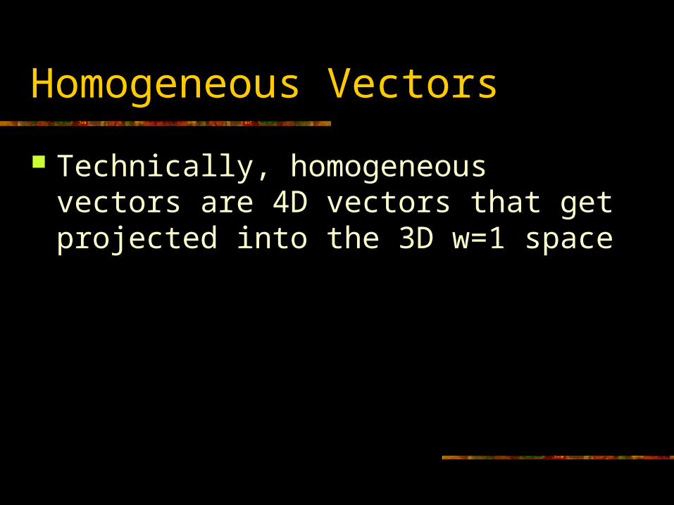
Homogeneous Vectors
Technically, homogeneous vectors are 4D vectors that get projected into the 3D w=1 space
w
z
w
y
w
xwzyx v
v
v
v
v
vvvvv
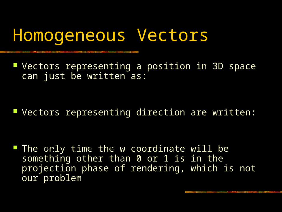
Homogeneous Vectors
Vectors representing a position in 3D space can just be written as:
Vectors representing direction are written:
The only time the w coordinate will be something other than 0 or 1 is in the projection phase of rendering, which is not our problem
1zyx vvv
0zyx vvv
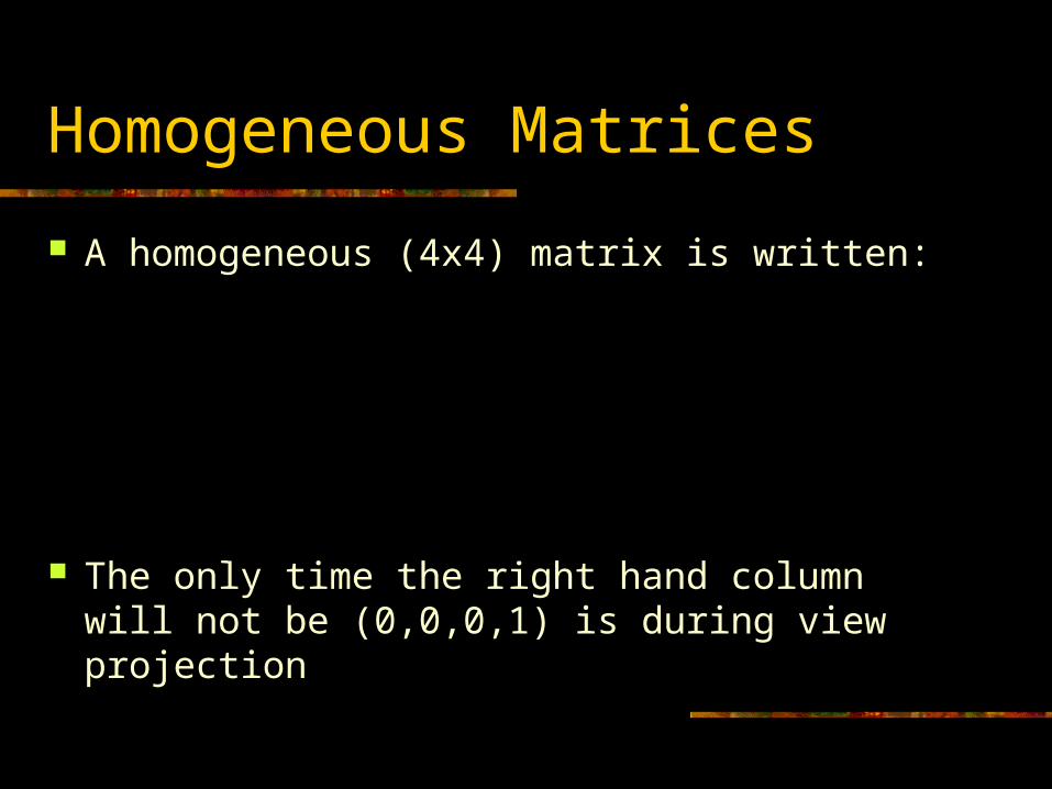
Homogeneous Matrices
A homogeneous (4x4) matrix is written:
The only time the right hand column will not be (0,0,0,1) is during view projection
1
0
0
0
zyx
zyx
zyx
zyx
ddd
ccc
bbb
aaa
M
Position Vector Dot Matrix
1
1
w
zzzzyzxz
yyzyyyxy
xxzxyxxx
zyx
v
dcvbvavv
dcvbvavv
dcvbvavv
vvv
Mvv
v
dcbav zyx vvv
1
0
0
0
zyx
zyx
zyx
zyx
ddd
ccc
bbb
aaa
M
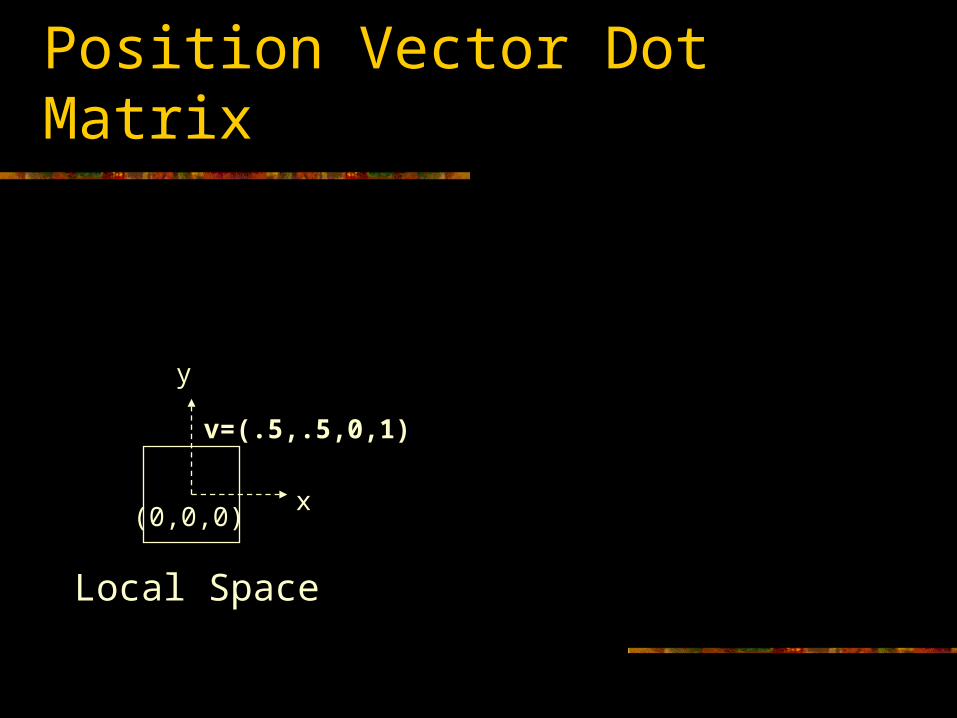
Position Vector Dot Matrix
dcbav zyx vvv
v=(.5,.5,0,1)
x
y
Local Space
(0,0,0)
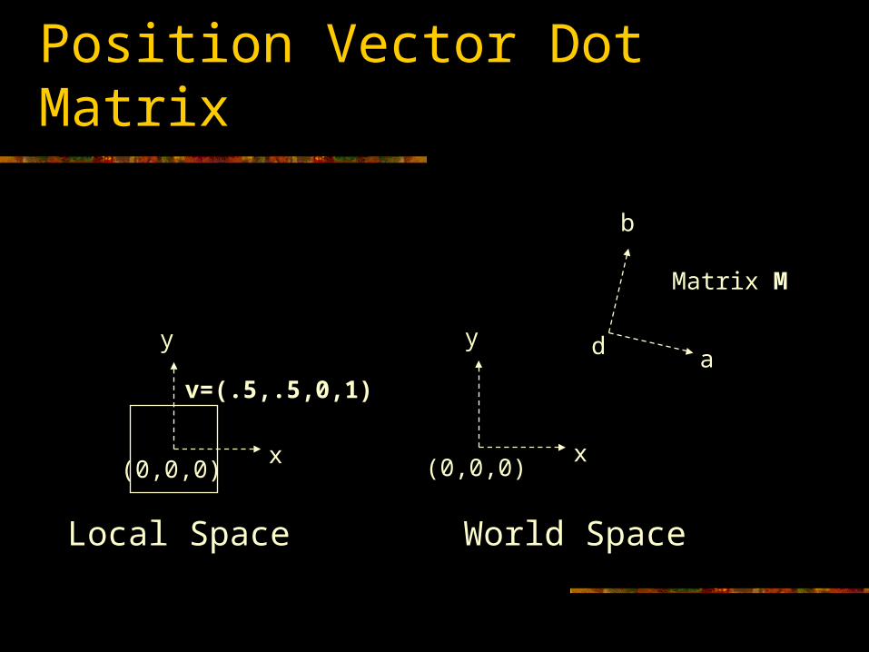
Position Vector Dot Matrix
dcbav zyx vvv
v=(.5,.5,0,1)
x
y
Local Space
(0,0,0)x
y
World Space
(0,0,0)
a
b
d
Matrix M
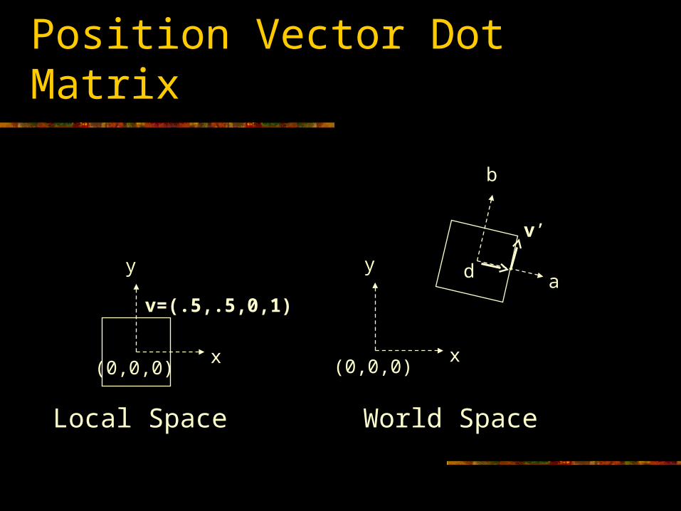
Position Vector Dot Matrix
dcbav zyx vvv
v=(.5,.5,0,1)
x
y
Local Space
(0,0,0)x
y
World Space
(0,0,0)
a
b
d
v’
Inversion
If M transforms v into world space, then M-1 transforms v’ back into local space
IMM
Mvv
Mvv
1
1
Direction Vector Dot Matrix
0
0
w
zzzyzxz
yzyyyxy
xzxyxxx
zyx
v
cvbvavv
cvbvavv
cvbvavv
vvv
Mvv
v
cbav zyx vvv
1
0
0
0
zyx
zyx
zyx
zyx
ddd
ccc
bbb
aaa
M
Matrix Dot Matrix (4x4)
1
0
0
0
zyx
zyx
zyx
zyx
ddd
ccc
bbb
aaa
MNMM
The row vectors of M’ are the row vectors of M transformed by matrix N
Notice that a, b, and c transform as direction vectors and d transforms as a position
Identity
Take one more look at the identity matrix It’s a axis lines up with x, b lines up with y, and c lines up with z Position d is at the origin Therefore, it represents a transformation with no rotation or
translation
1000
0100
0010
0001
I
Human Facial Expressions
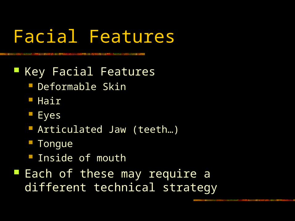
Facial Features
Key Facial Features Deformable Skin Hair Eyes Articulated Jaw (teeth…) Tongue Inside of mouth
Each of these may require a different technical strategy
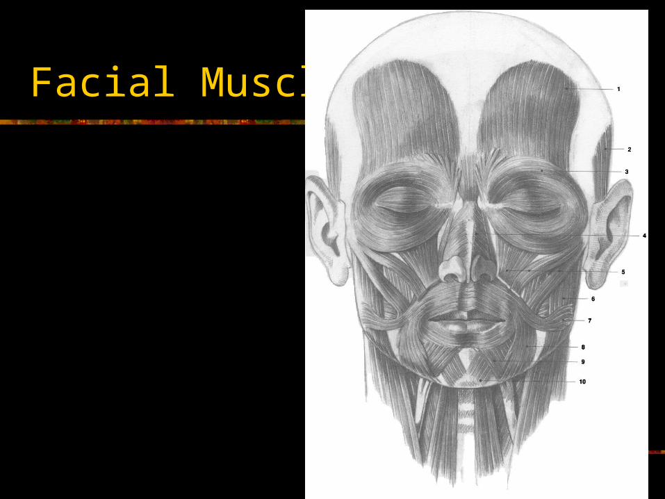
Facial Muscles
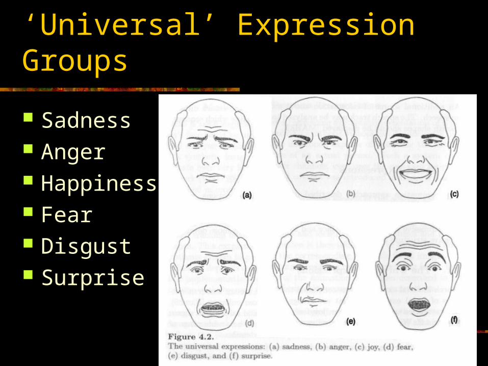
‘Universal’ Expression Groups
Sadness Anger Happiness Fear Disgust Surprise
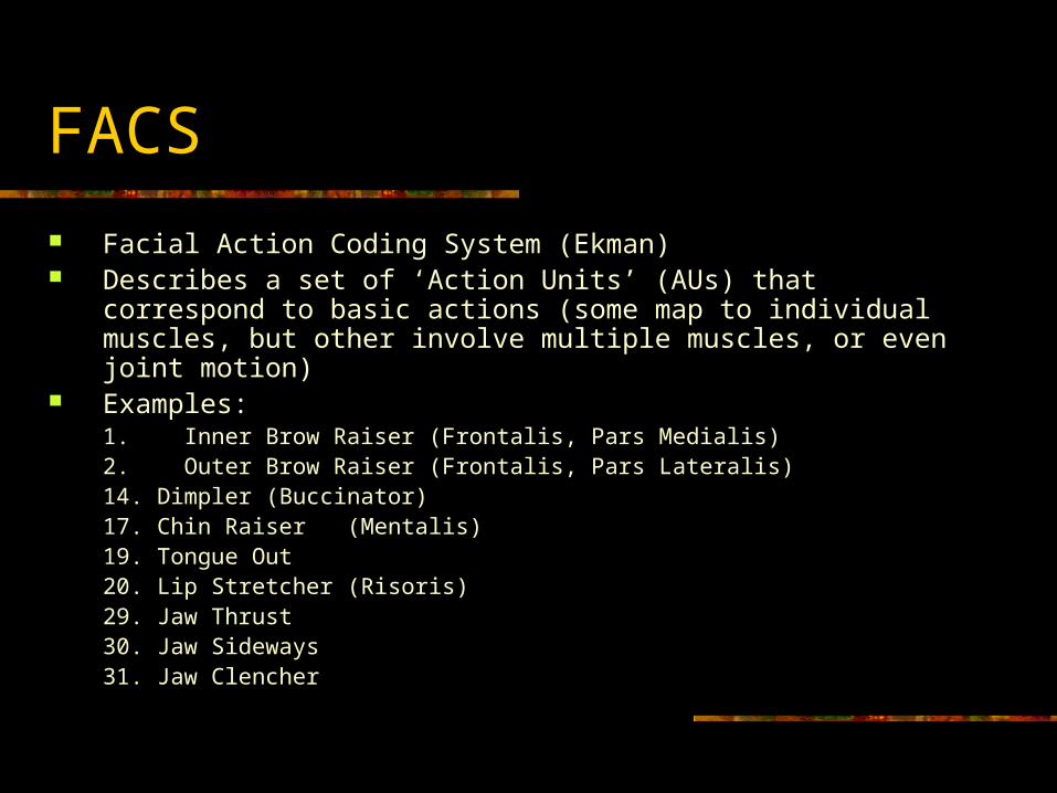
FACS
Facial Action Coding System (Ekman) Describes a set of ‘Action Units’ (AUs) that correspond to basic
actions (some map to individual muscles, but other involve multiple muscles, or even joint motion)
Examples:1. Inner Brow Raiser (Frontalis, Pars Medialis)2. Outer Brow Raiser (Frontalis, Pars Lateralis)14. Dimpler (Buccinator)17. Chin Raiser (Mentalis)19. Tongue Out20. Lip Stretcher (Risoris)29. Jaw Thrust30. Jaw Sideways31. Jaw Clencher
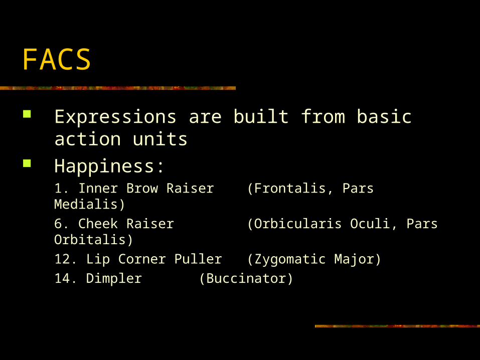
FACS
Expressions are built from basic action units Happiness:
1. Inner Brow Raiser (Frontalis, Pars Medialis)
6. Cheek Raiser (Orbicularis Oculi, Pars Orbitalis)
12. Lip Corner Puller (Zygomatic Major)
14. Dimpler (Buccinator)
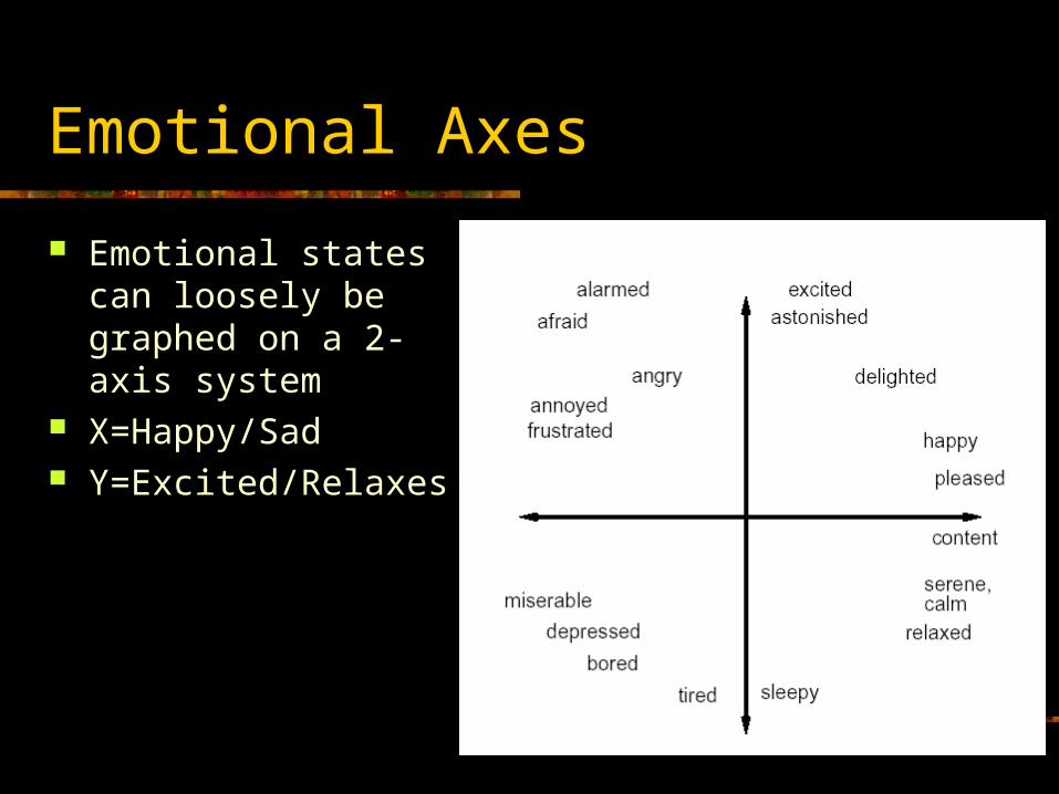
Emotional Axes
Emotional states can loosely be graphed on a 2-axis system
X=Happy/Sad Y=Excited/Relaxes
Wrinkles
Wrinkles are important visual indicators of facial expressions, and have often been overlooked in computer animation
Facial Expression Reading
Books “Computer Facial Animation” (Parke, Waters) “The Artist’s Complete Guide to Facial
Expression” (Faigin) “The Expression of Emotions in Man and
Animals” (Darwin) Papers
“A Survey of Facial Modeling and Animation Techniques” (Noh)
Facial Modeling
Facial Modeling
Preparing the facial geometry and all the necessary expressions can be a lot of work
There are several categories of facial modeling techniques Traditional modeling (in an interactive 3D modeler) Photograph & digitize (in 2D with a mouse) Sculpt & digitize (with a 3D digitizer) Scanning (laser) Vision (2D image or video)
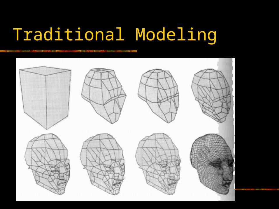
Traditional Modeling
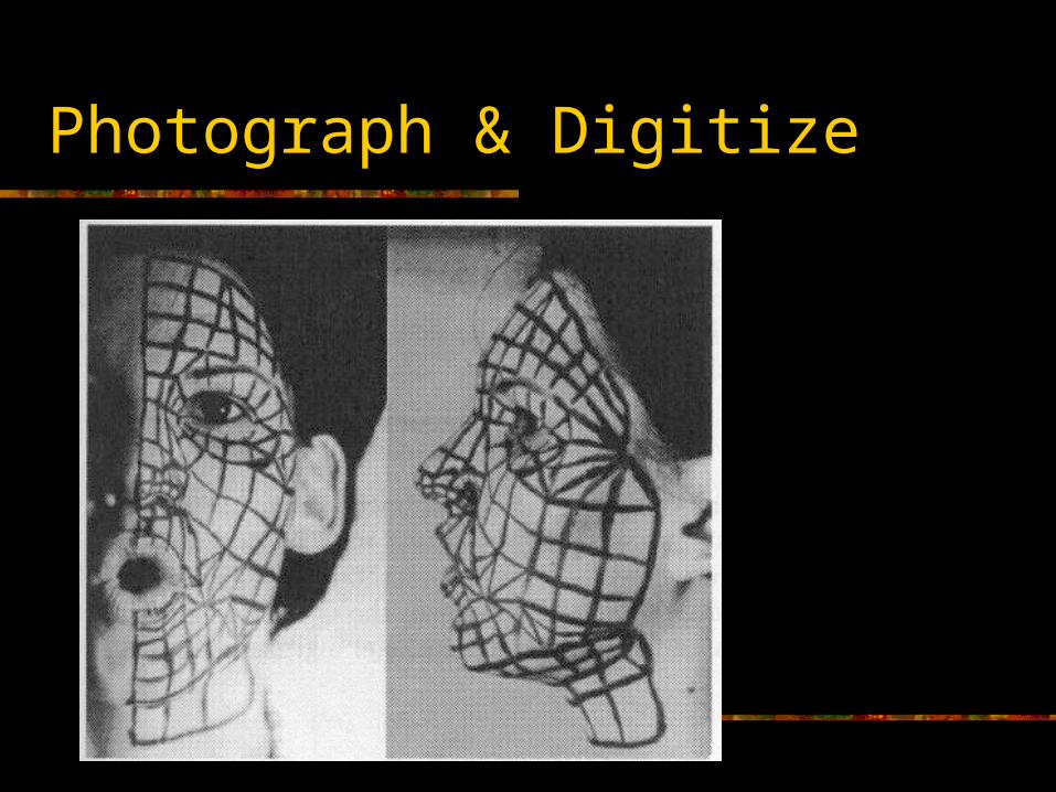
Photograph & Digitize
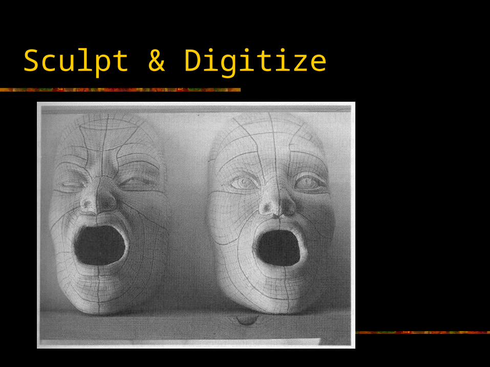
Sculpt & Digitize
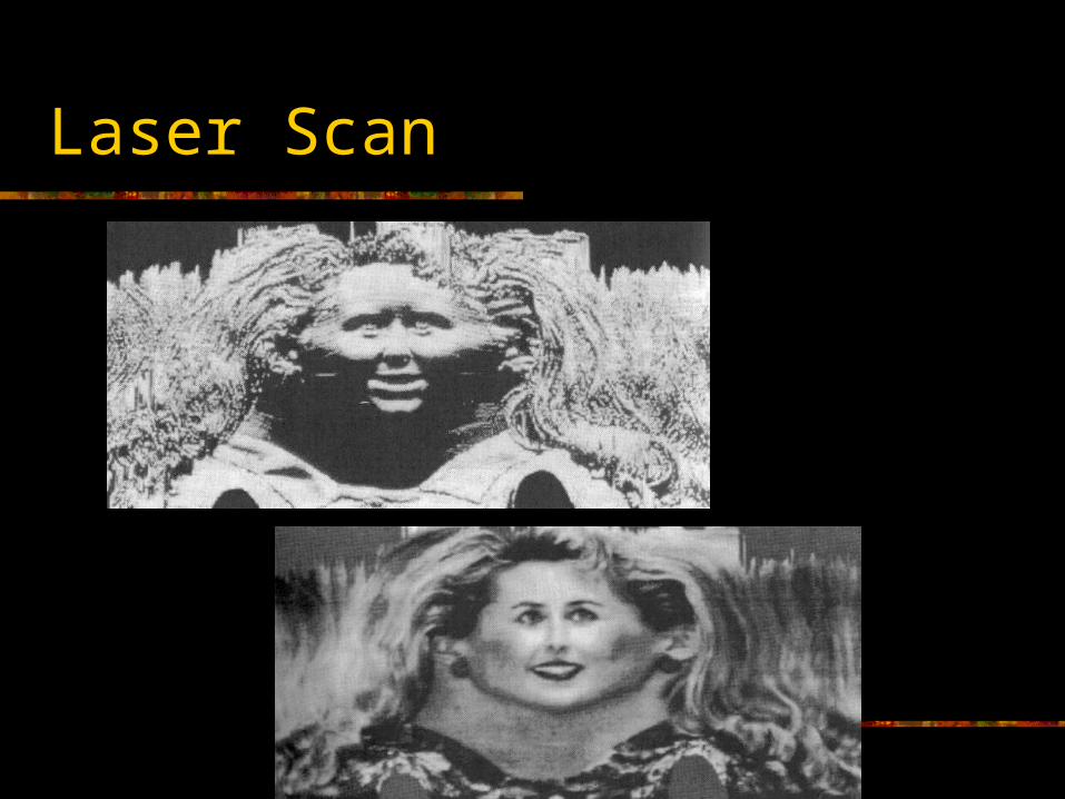
Laser Scan
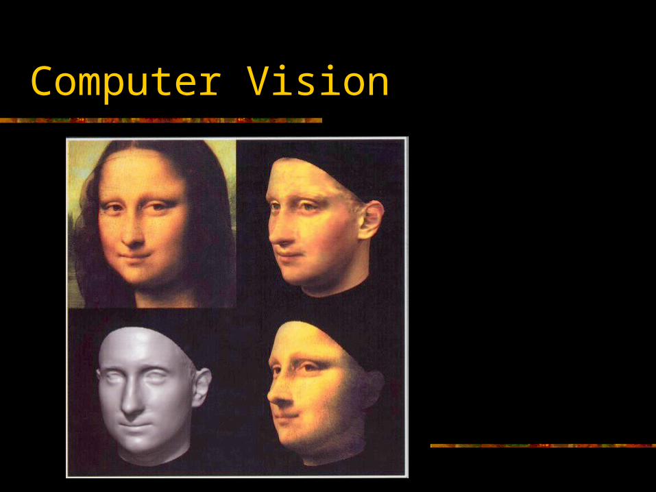
Computer Vision
Facial Expression Techniques
Facial Expression Techniques
Texture swapping/blending Bones (joints & smooth skin) Shape interpolation (morphing) Artificial muscles (FFDs…) Anatomical simulation
Texture Based Methods
A very low quality approach to doing facial expressions is simply to swap or blend between various texture maps on the face
Obviously, this is pretty cheezy and doesn’t really model actual skin deformations
It might be acceptable for low detail (distant) characters in video games
However, texture based methods can be combined with geometric methods to achieve certain useful effects Wrinkles Vascular expression (blushing)
Bone Based Methods
Using joints & skinning to do the jaw and eyes makes a lot of sense
One can also use a pretty standard skeleton system to do facial muscles and skin deformations, using the blend weights in the skinning
This gives quite a lot of control and is adequate for medium quality animation
Shape Interpolation Methods
One of the most popular methods in practice is to use shape interpolation
Several different expressions are sculpted and blended to generate a final expression
One can interpolate the entire face (happy to sad) or more localized zones (left eyelid, brow, nostril flare…)
Pose Space Deformation
PSD is an advanced shape interpolation technique that can be used for both facial expressions and other skin deformations
Read that paper about it on the class web page
Artificial Muscle Methods
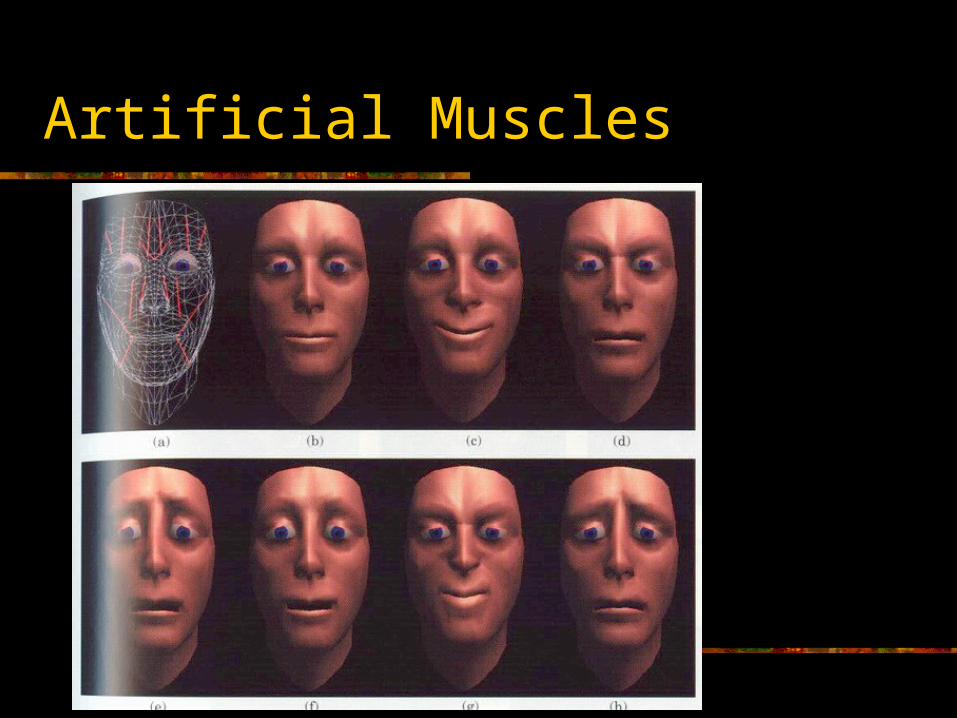
With this technique, muscles are modeled as deformations that affect local regions of the face
The deformations can be built from simple operations, joints, interpolation targets, FFDs, or other techniques
Artificial Muscles
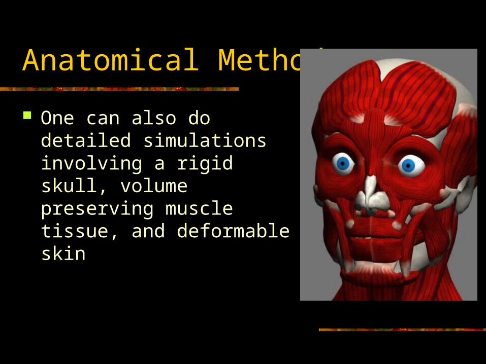
Anatomical Methods
One can also do detailed simulations involving a rigid skull, volume preserving muscle tissue, and deformable skin
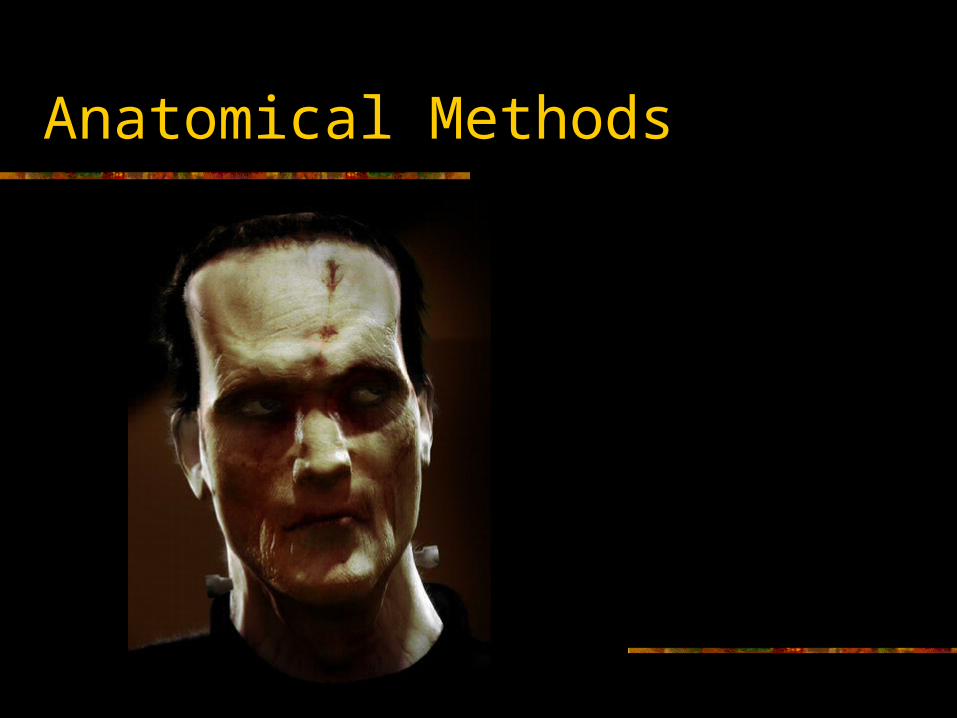
Anatomical Methods

Shape Interpolation
Shape Interpolation
Shape interpolation allows blending between and combining several pre-sculpted expressions to generate a final expression
It is a very popular technique, as it ultimately can give total control over every vertex if necessary
However, it tends to require a lot of set up time It goes by many names:
Morphing Morph Targets Multi-Target Blending Vertex Blending Geometry Interpolation etc.
Interpolation Targets
One starts with a 3D model for the face in a neutral expression, known as the ‘base’
Then, several individual ‘targets’ are created by moving vertices from the base model
The topology of the targets must be the same as the base model (i.e., same number of verts & triangles, and same connectivity)
Each target is controlled by a DOF Фi that will range from 0 to 1
Shape Interpolation Algorithm
To compute a blended vertex position:
The blended position is the base position plus a contribution from each target whose DOF value is greater than 0 (targets with a DOF value of 0 are essentially ‘off’ and have no effect)
If multiple targets affect the same vertex, their results combine in a ‘reasonable’ way
baseiibase vvvv
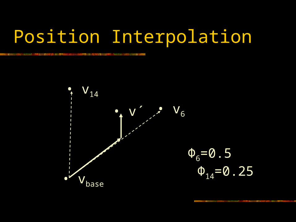
Position Interpolation
• vbase
• v6
• v14
• v´
Φ6=0.5 Φ14=0.25
Normal Interpolation
To compute the blended normal:
Note: if the normal is going to undergo further processing (i.e., skinning), we might be able to postpone the normalization step until later
*
*
*
n
nn
nnnn
baseiibase
Shape Interpolation and Skinning
Usually, the shape interpolation is done in the skin’s local space
After the shape is blended, it can be attached to the skeleton through the smooth skinning algorithm
Morph Target DOFs
We need DOFs to control the interpolation They will generally range from 0 to 1 This is why it is nice to have a DOF class
that can be used by joints, morph targets, or anything else we may want to animate
Higher level code does not need to distinguish between animating an elbow DOF and animating an eyebrow DOF
Target Storage
Morph targets can take up a lot of memory. This is a big issue for video games, but less of a problem in movies.
The base model is typically stored in whatever fashion a 3D model would be stored internally (verts, normals, triangles, texture maps, texture coordinates…)
The targets, however, don’t need all of that information, as much of it will remain constant (triangles, texture maps…)
Also, most target expressions will only modify a small percentage of the verts
Therefore, the targets really only need to store the positions and normals of the vertices that have moved away from the base position (and the indices of those verts)
Target Storage
Also, we don’t need to store the full position and normal, only the difference from the base position and base normal
i.e., other than storing v3, we store v3-vbase
There are two main advantages of doing this: Fewer vector subtractions at runtime (saves time) As the deltas will typically be small, we should be able
to get better compression (saves space)
Target Storage
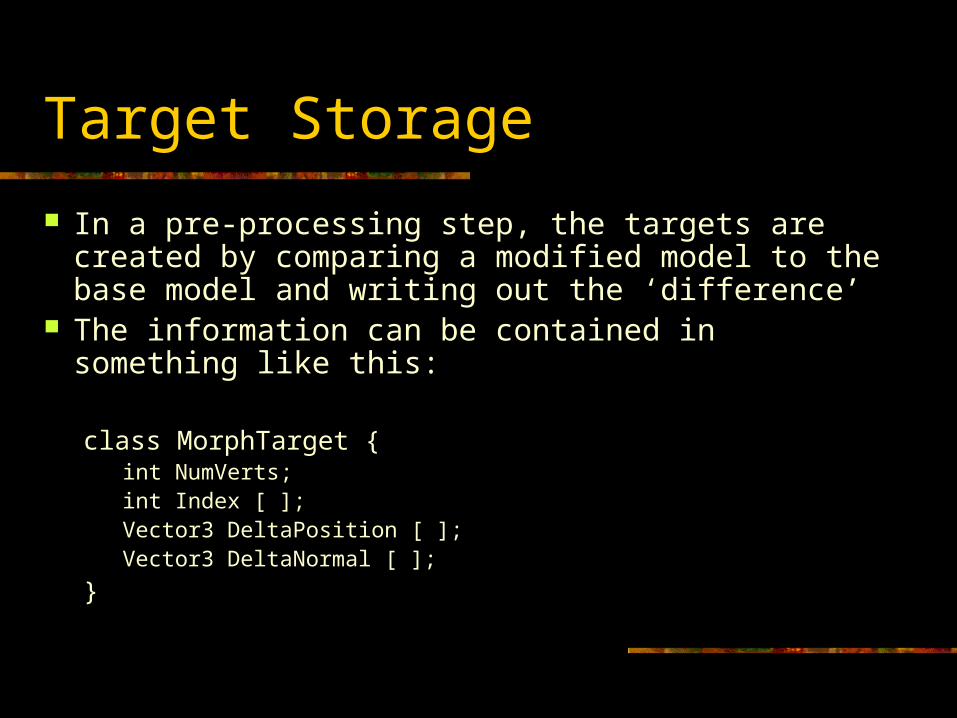
In a pre-processing step, the targets are created by comparing a modified model to the base model and writing out the ‘difference’
The information can be contained in something like this:
class MorphTarget {int NumVerts;int Index [ ];Vector3 DeltaPosition [ ];Vector3 DeltaNormal [ ];
}
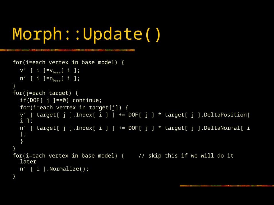
Morph::Update()
for(i=each vertex in base model) {
v’ [ i ]=vbase[ i ];
n’ [ i ]=nbase[ i ];}for(j=each target) {
if(DOF[ j ]==0) continue;for(i=each vertex in target[j]) {
v’ [ target[ j ].Index[ i ] ] += DOF[ j ] * target[ j ].DeltaPosition[ i ];n’ [ target[ j ].Index[ i ] ] += DOF[ j ] * target[ j ].DeltaNormal[ i ];
}}for(i=each vertex in base model) { // skip this if we will do it later
n’ [ i ].Normalize();}
Colors and Other Properties
In addition to interpolating the positions and normals, one can interpolate other per-vertex data: Colors Alpha Texture coordinates Auxiliary shader properties
Wrinkles
One application of auxiliary data interpolation is adding wrinkles Every vertex stores an auxiliary property indicating how wrinkled
that area is On the base model, this property would probably be 0 in most of the
verts, indicating an unwrinkled state Target expressions can have this property set at or near 1 in wrinkled
areas When facial expressions are blended, this property is blended per
vertex just like the positions and normals (but should be clamped between 0 and 1 when done)
For rendering, this value is used as a scale factor on a wrinkle texture map that is blended with the main face texture
Even better, one could use a wrinkle bump map or displacement map

Rigging
Rigging
A rig is like a virtual puppet A rig contains has several DOFs, each
corresponding to an animatable parameter within the puppet
DOFs can control: Joint rotations, translations Morph targets Other things…
Higher level animation code will specify values for the DOFs (i.e., pose the rig)
Rigging
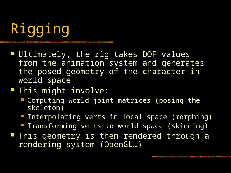
Ultimately, the rig takes DOF values from the animation system and generates the posed geometry of the character in world space
This might involve: Computing world joint matrices (posing the skeleton) Interpolating verts in local space (morphing) Transforming verts to world space (skinning)
This geometry is then rendered through a rendering system (OpenGL…)
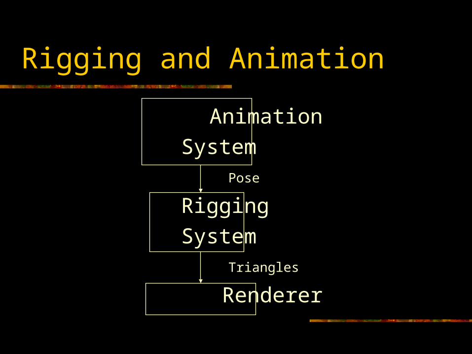
Rigging and Animation
Animation
SystemPose
Rigging
SystemTriangles
Renderer
DOF Types
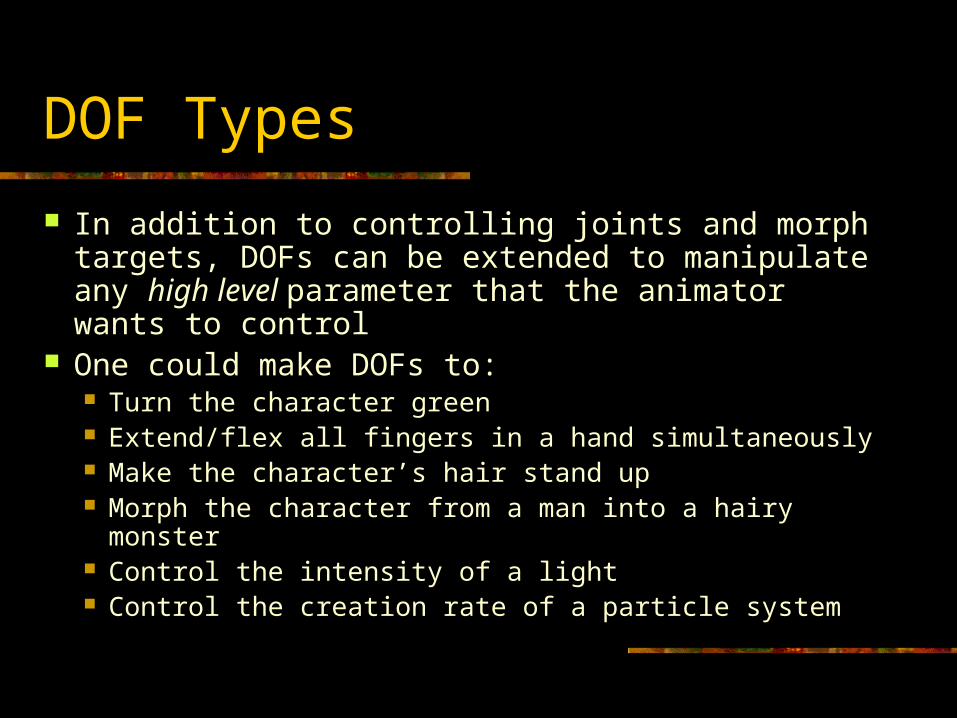
In addition to controlling joints and morph targets, DOFs can be extended to manipulate any high level parameter that the animator wants to control
One could make DOFs to: Turn the character green Extend/flex all fingers in a hand simultaneously Make the character’s hair stand up Morph the character from a man into a hairy monster Control the intensity of a light Control the creation rate of a particle system
Grouping DOFs
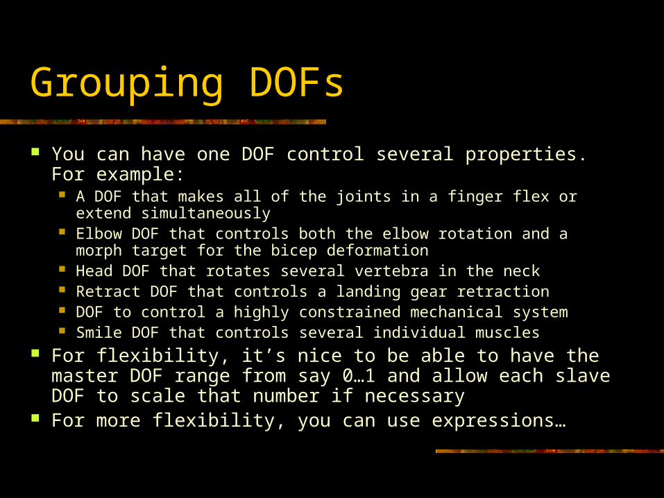
You can have one DOF control several properties. For example: A DOF that makes all of the joints in a finger flex or extend
simultaneously Elbow DOF that controls both the elbow rotation and a morph target for
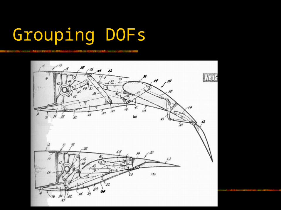
the bicep deformation Head DOF that rotates several vertebra in the neck Retract DOF that controls a landing gear retraction DOF to control a highly constrained mechanical system Smile DOF that controls several individual muscles
For flexibility, it’s nice to be able to have the master DOF range from say 0…1 and allow each slave DOF to scale that number if necessary
For more flexibility, you can use expressions…
Grouping DOFs
DOF Expressions
For more flexibility, its nice to be able to run arbitrary expressions with DOF values
An expression takes one or more DOFs as inputs and sets an external DOF as output
An expression can literally be any mathematical expression:
DOF[27] = DOF[3] * 6.0 – sin (DOF[2]) + DOF[14]
Rather than being hard-coded in C++, it’s nice if expressions can be interpreted at runtime
Rig Mappings
A rig can be implemented as an array of pointers to DOFs The DOF order is important and must be consistent
between the rigging & animation systems The DOFs themselves exist as internal objects used in the
skeleton, morph system, and in expressions Normally, we would have a single rig that controls all of the
character’s DOFs that we wish to animate Alternately, we could:
Have a rig that controls a subset of a character’s DOFs Have one rig that maps to more than one character Have several different rigs for the same character to be used for
different purposes
Push vs. Pull
There are lots of different ways to implement rigging
One approach is to have the rig ‘push’ data into the DOFs. The other is to have the DOFs ‘pull’ data from the rig. There are several other subtle details to work out…
Pushing is probably better, as it allows for multiple rig configurations to map to the same DOF a little bit easier
Pushing DOF Values
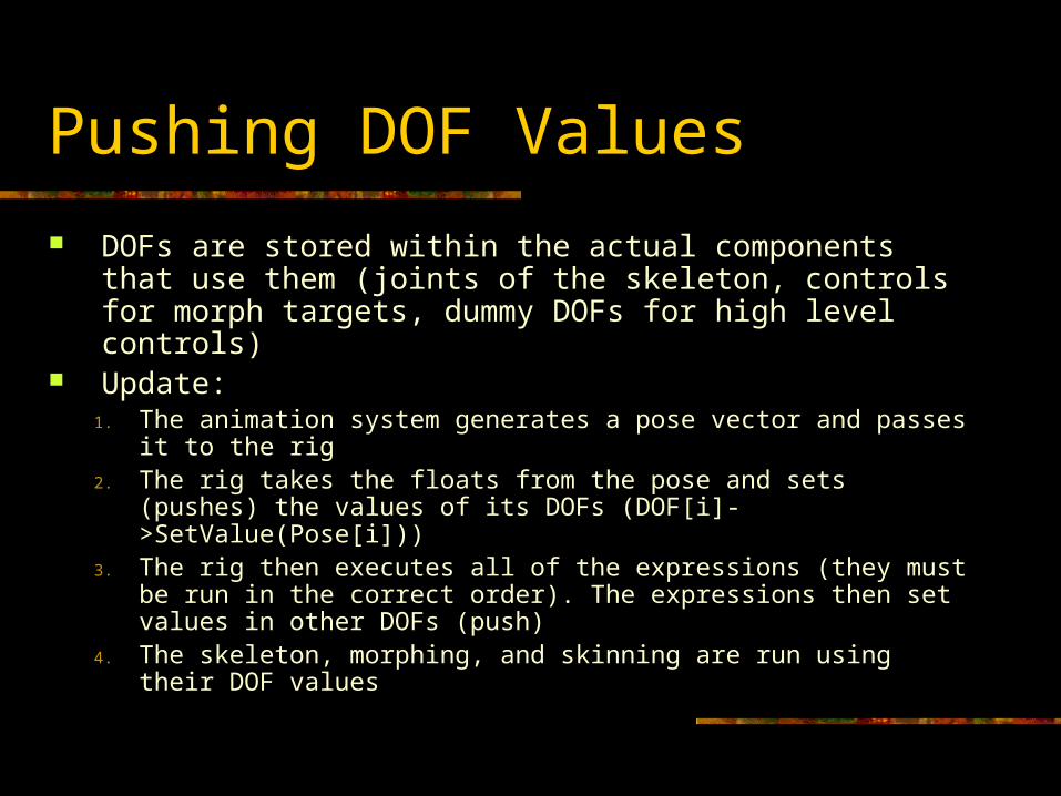
DOFs are stored within the actual components that use them (joints of the skeleton, controls for morph targets, dummy DOFs for high level controls)
Update:1. The animation system generates a pose vector and passes it
to the rig2. The rig takes the floats from the pose and sets (pushes) the
values of its DOFs (DOF[i]->SetValue(Pose[i]))3. The rig then executes all of the expressions (they must be run
in the correct order). The expressions then set values in other DOFs (push)
4. The skeleton, morphing, and skinning are run using their DOF values
*Rig Mapping
Minimalist Rigging
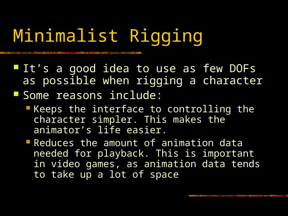
It’s a good idea to use as few DOFs as possible when rigging a character
Some reasons include: Keeps the interface to controlling the character
simpler. This makes the animator’s life easier. Reduces the amount of animation data needed
for playback. This is important in video games, as animation data tends to take up a lot of space
Full Body Morphing
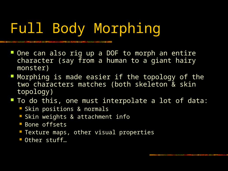
One can also rig up a DOF to morph an entire character (say from a human to a giant hairy monster)
Morphing is made easier if the topology of the two characters matches (both skeleton & skin topology)
To do this, one must interpolate a lot of data: Skin positions & normals Skin weights & attachment info Bone offsets Texture maps, other visual properties Other stuff…
Smooth Skin Algorithm
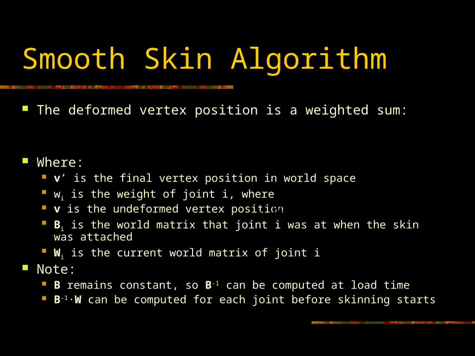
The deformed vertex position is a weighted sum:
Where: v’ is the final vertex position in world space wi is the weight of joint i, where v is the undeformed vertex position Bi is the world matrix that joint i was at when the skin was attached Wi is the current world matrix of joint i
Note: B remains constant, so B-1 can be computed at load time B-1·W can be computed for each joint before skinning starts
iiiw WBvv 1
1iw
Top Related