


Languages
Pages
Legal


1
Explaining the principles of
Photonics and optical
communications
Teacher’s notes
Copyright Photonic Education Systems 2004
2
Safety notice
This product includes a low power (<1mW) visible red laser, which has the
same characteristics as a laser pointer. Improper use of the laser, including
pointing the beam at other people or staring into the beam, may damage the eye.
You must read and then conform to safety guidelines set out by your state
educational department when using this product. Tell students about the possible
dangers of lasers.
• Never point the laser at a person.
• Never stare into the laser beam.
• Make sure that the user informs others that the laser is on and where
the beam is directed.
The light emitting diodes on the second transmitter board are safe. They are not
lasers.

3
IntroductionPhotonic technologies are widely used and have had an enormous impact on our lives. The
Photonics and Optical Communications Experiment has been designed to help you teach the
optics, Photonics and communications components of the science syllabi. The package
contains a working optical communications system, with coloured lights and audible radio
sound designed to capture the student’s attention. After a hands-on class with the Optical
Communications Experiment the student will understand the physical principles of photonics
that allows modern optical communication.
You may wish to adapt the experiments to your particular curriculum or educational
goal. That is why we have made these notes available to you in electronic form. We give you
permission to extract parts of these notes and write your own lesson plans around them on
your word processor and then hand out hard copies to your class. We request that you email
or send us your notes so that we can improve our notes for future users.
Photonics and Optical CommunicationsPhotonics is the science and technology of light. Some aspects of photonics include:
• Generation of light, for example using lasers or light emitting diodes
• Detection of light, for example with silicon photodiodes that supply an electrical
current proportional to the intensity of the light that falls upon them
• Information storage and retrieval using light, for example compact disks
• Measuring with light, for example interferometric length measurement or gas
detection
• Communicating with light, by encoding information on a beam of light or a guided
light wave
Photonics has made a particularly large impact on everyday communications. Therefore, the
experiments presented here concentrate on communicating with light. Because of Photonics
we are now able to send vast amounts of information around the world. This has enabled
technologies such as the Internet and allowed cheap international phone calls, connecting
people around the globe.
Communicating with light started many centuries ago with smoke signals, for
example. Puffs of smoke could carry information because the clouds reflected light rays that
could be observed from a distance. This principle is similar to the dots-and-dashes system
used in Morse code. Although smoke signals are slow and can only travel short distances,
they were an interesting early form of optical communication.
Can you think of other ways of sending information using light? Hint:
sailors, scuba divers and aircraft pilots all send signals using light.
Modern optical communications allow much faster communication over greater
distances than can be achieved using smoke signals. As with smoke signals, we can send a
message using light by turning it on and off, or changing the light intensity. Using smoke
signals, we could imagine a skilled person letting rise a smoke signal approximately once per
second, or one bit of information per second. However, an optical fibre connecting two
continents is now capable of sending more than 1 Terrabit or 1,000,000,000,000 bits of

4
information per second. This is the equivalent of more than 100,000,000 simultaneous
telephone calls or 40,000,000 pages of text every second.
How many years would it take you to speak every word that is transmitted
down an optical fibre every second? (Hint: Assume 2 words per second for
each telephone call, and up to 100,000,000 simultaneous telephone calls)
Optical fibre is now used extensively to send information between continents and
cities. Figure 1 shows current optical fibre links around the globe. These links have mostly
replaced satellite communications because they can carry much more information cheaply.
Figure 1. Optical fibre connections across the world around in year 2000.(Beaufils, Opt. Fiber Tech. 6 15 (2000))
The kit: Becoming familiar with the componentsExamine the experimental components. The function and controls of each component are
described below.
Three radios or CD players. These are not supplied in the kit. We use the stereo headphone
socket on each radio as an audio signal source. It’s best that the radios or CD players are each
playing easily differentiable sounds (classical, popular and talk-balk radio, for example).
Become familiar with the volume and tuning controls, and confirm that the internal speaker
(if there is one) is disabled when you connect a cable to the headphone socket.
Three stereo cables. These are used to connect the headphone socket on the radios or CD
players to the audio input socket on the laser or LED transmitter units.
One LED transmitter unit. The headphone socket on each radio can be connected to an
audio input socket on the LED transmitter unit. Each signal is encoded onto the light emitted
by either a blue, green or
red coloured LED. The
information is represented
by changes in the light
intensity. There is a
power switch. Each
individual LED can also
be tuned on or off. Find
the switches for each
LED.
PowerLED on/off
LED’s
(not visible)Audio in
sockets
PowerLED on/off
LED’s
(not visible)Audio in
sockets

5
One receiver unit. The silicon photodiode on this unit detects the light carrying the audio
signal, producing a current that is proportional to the intensity of the light striking it. The
circuity retrieves the audio
signal and then plays it
through the inbuilt speaker.
There is a power switch and a
volume knob.
One laser transmitter unit. The headphone socket from a single radio or CD player is
connected to the audio socket on the laser transmitter with a stereo cable. It encodes the audio
signal onto a laser beam. There is also a microphone on the laser transmitter unit that can
supply an alternative audio signal. You can switch between the audio socket and microphone
inputs with a
switch. There
is a power
switch.
Three colour filters. The red, green and blue filter will only allow light from the red, green
and blue LED’s respectively to pass, absorbing the other two colours. This is used to separate
the colours before they reach the receiver.
Clear plastic rods. These are used to guide light by total internal reflection from the LED
transmitter unit to the receiver unit. This simulates an optical fibre.
Signal generator. This is not supplied in the kit. A software based signal generator that can
run off a PC, and which is supplied, can be substituted for the signal generator. The signal
generator can be connected to the LED transmitter unit using the pins on the board. This
enables a pure tone to be transmitted.
Glass or beaker filled with water and a few drops of milk. This is not supplied in the kit.
This is used to demonstrate total internal reflection.
Sample of optical fibre. For inspection.
Power
Volume
Photo-
Diode
(not visible)
Power
Volume
Photo-
Diode
(not visible)
Audio in
socket
Microphone
Source select
Laser output
Power
Audio in
socket
Microphone
Source select
Laser output
Power

6
Experiments
Experiment 1 - Modulated light carries information
Aim
To show simple audio information can be encoded onto light by modulating the light
intensity.
Equipment
• Signal generator or PC with supplied signal generator software
• Cable with alligator clips to connect signal generator and LED transmitter unit, or
stereo cable to connect PC headphone socket and LED transmitter unit
• LED transmitter unit, with only one LED turned on
• Receiver unit (check it is on and the volume is turned up)
Light
Detector
Signal
Generator
LED
transmitter
unitLight
Detector
Signal
Generator
LED
transmitter
unit
Schematic of the arrangement for experiment ‘Modulated light carries information’
Method
• Turn the frequency of the signal generator to around 1 Hz and turn the output voltage
down to its minimum value.
• Connect the signal generator output to the LED transmitter unit, and ensure the LED
transmitter is on. Check that you have connected the signal generator to the LED that
is on.
• Slowly turn up the output voltage on the signal generator so the LED light starts to
fade and grow strongly.
• Place the photodiode on the receiver unit 10 cm away from the LED. Turn the receiver
unit on.
• Increase the frequency of the signal generator and listen to the change in the audio
frequency
• Record what over what frequency range you can hear a tone (Note that audio
frequencies below around 15 Hz are out of the range of human hearing).
What changing light property contains the information thatrepresents sound?

7
What does this demonstrate?
The student observes the flashing light and simultaneously hears a tone. The flashing LED
and the audio frequencies change together when the signal generator frequency is changed.
The student understands that simple audio information can be encoded onto light by
modulating the light intensity.
Extra activity
• Ask the student to point the receiver around the room.
• The student should generate an audio buzz from the fluorescent lights, which flash at
100 Hz.
• The student should then do the same with an incandescent light, which do not flash,
and thus will give no audio buzz.
• Ask the students what can they deduce about these two light sources.
• The students should deduce that fluorescent lights flash and incandescent lights have
continuous output.
• On comparison with audible tones from the frequency generator the student should be
able to estimate the frequency of the flashing.

8
Experiment 2 - Light can carry complex information
Aim
To demonstrate that complicated information can be encoded onto light.
Equipment
• Radio or CD player
• Stereo cable
• LED transmitter unit, with only one LED on
• Receiver unit (check the volume is turned up)
Light
Detector
Radio
or CD player
LED
transmitter
unit
Light
Detector
Radio
or CD player
Light
Detector
Radio
or CD player
LED
transmitter
unit
Schematic of the arrangement for ‘Light can carry complex information’.
Method
• Use the stereo cable to connect the headphone socket on the radio or CD player to the
audio input socket of the to the LED transmitter unit
• Check that you have connected the radio or CD player to the LED that is on.
• Place the photodiode on the receiver unit 10 cm away from the LED. Turn the receiver
unit on.
• The radio station or CD should be audible from the speaker on the receiver unit. If not
check everything is on, the volume knob is turned up and you have connected the
correct LED.
• Block the light from the LED. The sound should stop.
What does this demonstrate?
This demonstrates that complicated information, in this case music, can be encoded onto
light. The student should be able to understand that other types of information, such as
internet data, could also be encoded onto light.
How far can you move the receiver away from the transmitterbefore you can no longer hear the sound? What determines thisdistance?

9
Experiment 3 - Total internal reflection
AimTo demonstrate total internal reflection. This allows light to be guided along the core of an
optical fibre.
Equipment• Glass or beaker of water with a few drops of milk in it (you may have to experiment to
optimise the amount of milk)
• Laser transmitter unit
Laser beam
Laser beam
Schematic of the arrangement for ‘Total internal reflection’.
A ray confined in a glass rod by total internal reflection.
Method• Turn on the laser transmitter board, to produce a laser beam.
• Direct the laser beam through the side of the glass, pointed up towards the surface.
• Observe that the beam is reflected at the interface between the water and the air because of
total internal reflection. To see this properly you may have to change you viewpoint and turn
the room lights off.
• Change the angle to observe the critical angle.
What does this demonstrate?Total internal reflection is very important in optical communications because it is the fundamental
principle enabling optical fibres. This experiment shows that a beam of light can be reflected by total
internal reflection at the interface between a high refractive index material (such as water or glass) and
a lower refractive index material. The guidance of a ray of light down a light guide, such as a rod of
clear plastic, is easily grasped after this demonstration with the addition of a simple picture tracing a
ray through a rod. A real optical fibre is composed of a glass core and a glass cladding. Because the
core has a higher refractive index than the cladding, light is confined to the core by total internal
reflection.

10
Experiment 4 - Signals in optical fibre go further!
Aim
To demonstrate that light can be guided.
Equipment
• Radio or CD player
• Stereo cable
• LED transmitter unit, with only one LED on
• Receiver unit (check the volume is tuned up)
• Straight and bent clear plastic rod (to simulate optical fibre)
• Sample of optical fibre
Method
• Separate the LED transmitter and receiver just far enough apart so that the clear
plastic rod can fit between the LED and the photodiode.
• Make sure the LED is connected to an audio signal from the radio or CD player
• Turn the transmitter and receiver on. You should hear the music playing softly on the
receiver unit’s speaker.
• Insert the straight plastic rod between the LED and the receiver unit, butting the ends
of the rods against the LED and photodiode. The sound volume should increase
considerably.
• Look at the end of the clear plastic rod with the LED on. It should be clear that a
considerable amount of light is guided by the rod.
• Try substituting the straight piece of clear plastic rod for the bent piece
• Try joining several pieces of clear plastic rod.
• Show a sample of optical fibre. Explain the connection with the clear plastic rod.
Light
DetectorRadio
or CD
player
Approximately 30 cm
Light
DetectorRadio
or CD
player
Approximately 30 cm
Schematic of the arrangement for ‘Signals in optical fibre go further’
What does this demonstrate?
Light can be guided, thus increasing the distance optical signals can be sent, and that light can
be guided around bends.
Can you think of two reasons optical fibre might be used in opticalcommunications?

11
Experiment 5 - Scattering Loss in optical fibre
Aim
To demonstrate that waveguides have loss.
Equipment
• Radio or CD player
• Stereo cable
• LED transmitter unit, with only one LED on
• Receiver unit (check the volume is turned up)
• Long and straight clear plastic rod
Method
• Ensure radio or CD player is tuned and on.
• Connect radio or CD player to LED transmitter unit with cable and turn transmitter on.
• Butt the LED against one end of the rod so the light is guided within the rod.
• Put the photodiode very close to the side of the rod, angled away from the transmitter.
• You should be able to hear the radio signal from the receiver speaker.
• Run the receiver along the length of the rod. The sound should fade the further the
receiver is moved away from the transmitter.
Radio
or CD
player
LED Receiver
unitLED
Transmitter
unit
Radio
or CD
player
LED Receiver
unit
LED Receiver
unitLED
Transmitter
unit
Schematic of the arrangement for ‘Scattering Loss in optical fibre’
What does this demonstrate?
Firstly, it shows that some of the light is scattered out of the rod. This is because
imperfections in the rod scatter the light at large angles. Some of the scattered rays do not
satisfy the condition for total internal reflection and are lost. Also, dust and dirt on the surface
can allow the light to escape. Secondly, this demonstrates that the guided wave becomes
weaker along the length of the waveguide because of scattering and absorption loses. To
compensate for loss in real optical fibre systems devices that amplify light (“optical
amplifiers”) are placed after every 80 km of fibre.
12
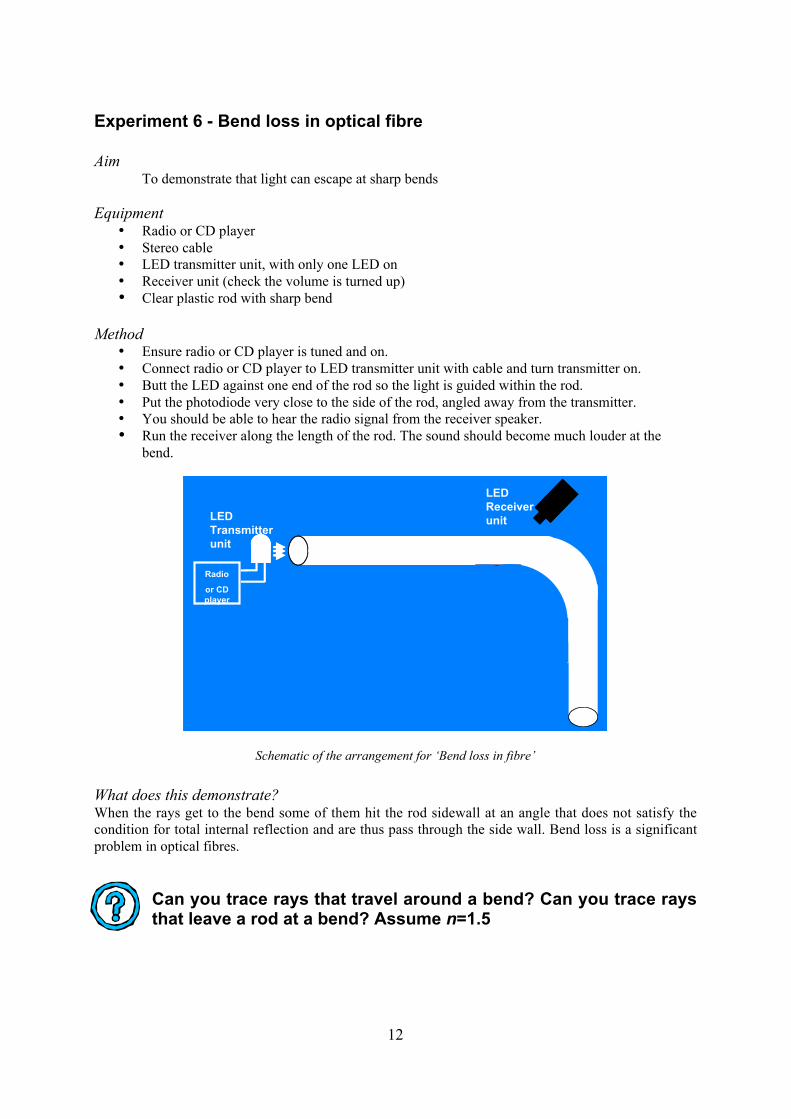
Experiment 6 - Bend loss in optical fibre
AimTo demonstrate that light can escape at sharp bends
Equipment• Radio or CD player
• Stereo cable
• LED transmitter unit, with only one LED on
• Receiver unit (check the volume is turned up)
• Clear plastic rod with sharp bend
Method• Ensure radio or CD player is tuned and on.
• Connect radio or CD player to LED transmitter unit with cable and turn transmitter on.
• Butt the LED against one end of the rod so the light is guided within the rod.
• Put the photodiode very close to the side of the rod, angled away from the transmitter.
• You should be able to hear the radio signal from the receiver speaker.
• Run the receiver along the length of the rod. The sound should become much louder at the
bend.
Radio
or CD
player
LED
Receiver
unitLED
Transmitter
unit
Radio
or CD
player
LED
Receiver
unitLED
Transmitter
unit
Schematic of the arrangement for ‘Bend loss in fibre’
What does this demonstrate?When the rays get to the bend some of them hit the rod sidewall at an angle that does not satisfy the
condition for total internal reflection and are thus pass through the side wall. Bend loss is a significant
problem in optical fibres.
Can you trace rays that travel around a bend? Can you trace raysthat leave a rod at a bend? Assume n=1.5

13
Experiment 7 - Wavelength Division Multiplexing
Aim
To demonstrate that more than one colour can be sent down an optical fibre,
increasing the information that can be sent.
Equipment
• Three radios or CD players.
• Three stereo cables
• LED transmitter unit, with all three LEDs on
• Receiver unit (check the volume is turned up)
• Red, green and blue optical filters
Method
• Turn the radios or CD players on one by one, ensuring they are playing different
sounds.
• Connect each radio to a different audio socket on the LED transmitter.
• Place the photodiode on the receiver unit about 10 cm from the LEDs.
• You should hear the sound originating from all three sources at once.
• Insert one coloured filter between the LEDs and photodiodes at a time. Only one radio
should be audible per filter.
Light
Detector
Coloured filter
Schematic of the arrangement for ‘Wavelength Division Multiplexing’
14
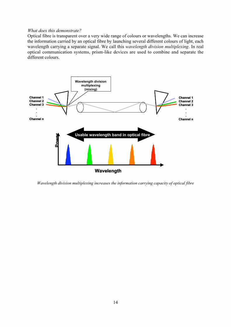
What does this demonstrate?
Optical fibre is transparent over a very wide range of colours or wavelengths. We can increase
the information carried by an optical fibre by launching several different colours of light, each
wavelength carrying a separate signal. We call this wavelength division multiplexing. In real
optical communication systems, prism-like devices are used to combine and separate the
different colours.
Wavelength division multiplexing increases the information carrying capacity of optical fibre
Channel 1
Channel 2
Channel 3
.
.
.
Channel n
Wavelength division
multiplexing
(mixing)
Wavelength
Po
we
r Usable wavelength band in optical fibre
Channel 1
Channel 2
Channel 3
.
.
.
Channel n
Channel 1
Channel 2
Channel 3
.
.
.
Channel n
Wavelength division
multiplexing
(mixing)
Wavelength
Po
we
r Usable wavelength band in optical fibre
Channel 1
Channel 2
Channel 3
.
.
.
Channel n

15
Experiment 8 - Free space communication with laser
Aim
To demonstrate that lasers can be used to send optically encoded information a long
way without using a waveguide.
Equipment
• One radio or CD player
• Stereo cable
• Laser transmitter unit
• Receiver unit (check the volume is tuned up)
Method
• Turn on the radios or CD player.
• Ensure laser transmitter is off!
• Connect the radio to the audio socket on the laser transmitter.
• Point the laser at a wall and turn it on.
• Place the photodiode on the receiver unit very close to the red spot on the wall to hear
the radio or CD.
• You can try using the microphone instead of the radio.
What does this demonstrate?
Sometimes it is not easy or convenient to use optical fibre. Installing optical fibre is also
expensive. In some cases it is easier and cheaper just to set up a laser between the sender and
the receiver (for example, between two office towers).

16
Who are Photonics Education Systems?We are a group of practicing scientists and engineers committed to helping people understand
the science and technology of photonics and optics. We work at The Optical Fibre
Technology Centre (www.oftc.usyd.edu.au) and the ARC Centre of Excellence for Ultrahigh
Bandwidth Devices for Optical Systems (www.cudos.org.au), both of which are research
centres within The University of Sydney. We developed the electronics, optics and these notes.
Photonic Education Systems was formed by us as a way of making the experiments available
to schools and other educational institutions. You can find out more about us on our website.
www.PhotonicsEducationSystems.com
Top Related