


Languages
Pages
Legal

Procedia CIRP 14 ( 2014 ) 599 – 604
Available online at www.sciencedirect.com
2212-8271 © 2014 Published by Elsevier B.V. Open access under CC BY-NC-ND license. Selection and peer-review under responsibility of the International Scientific Committee of the 6th CIRP International Conference on High Performance Cuttingdoi: 10.1016/j.procir.2014.03.021
ScienceDirect
6th CIRP International Conference on High Performance Cutting, HPC2014
Experimental Study and Modelling of Plastic Deformation of Cemented Carbide Tools in Turning
Anders Nordgrena*, Baktash Zargari Samanib, Rachid M´Saoubic a Sandvik Coromant AB, Stockholm, Sweden
b Sandvik SRP AB, Svedala, Sweden c Seco Tools AB, Fagersta, Sweden
* Corresponding author. Tel.: +46-70-6696608; fax: +46-8-7266561. E-mail address: [email protected]
Abstract
The plastic deformation of coated cemented carbide cutting tools was investigated. Testing methods were developed for the experimental determination of the high-temperature strength of cemented carbide (compressive strength, creep resistance). CVD-coated cemented carbide inserts were tested in continuous turning of quenched and tempered steel (AISI 4340). Cutting forces and edge temperature distributions were measured in 2D orthogonal turning. Normal stress distributions on the tool surface were estimated from measured cutting forces and tool-chip contact lengths. These data, together with measured high-temperature strength data for the cemented carbide, were introduced into a finite element model (ANSYS). The agreement between the predicted deformation and the experimental results was acceptable. The difference between the simulated and measured flank width on deformed cutting edges was approximately 15%. It has been demonstrated that numerical methods (FE) provide an opportunity to describe the effect of cutting conditions and tool material properties on tool behaviour quantitatively and in a systematic manner.
© 2014 The Authors. Published by Elsevier B.V. Selection and peer-review under responsibility of the International Scientific Committee of the 6th CIRP International Conference on High Performance Cutting.
Keywords: Cemented carbide; compressive strength; creep; metal cutting; turning; plastic deformation, cutting forces, edge temperatures, finite element, modeling;
1. Introduction
Increasing demands for higher rates of metal removal and productivity in modern manufacturing industry must be matched by enhancing the performance of cutting tools. Intense research on grade development by the tool industry has resulted in a continuous increase in grade performance to meet the demands of the manufacturing industry.
The plastic deformation of tools is one of the most important wear modes in metal cutting. Such deformation changes the geometry of the cutting edge, which often results in accelerated tool wear, increased cutting forces, risk of tool failure, vibrations and poor dimensional accuracy and surface finishes.
The high cost involved in obtaining machining data experimentally together with the opportunities to obtain a
better understanding of the basic mechanisms of the deformation process were the main motivations in the development of a methodology to study the plastic deformation of WC-Co cutting tools based on an experimental and numerical approach.
Empirical methods as well as analytical and numerical modelling have been applied to study different fundamental and technological aspects of the metal cutting process, such as chip formation, estimation of forces, stresses and temperatures and the prediction of wear and residual stresses on machined surfaces. Despite the significance of these phenomena, especially in continuous turning operations, rather few investigations concerning plastic deformation have been published. Often, the aim has been to predict the combinations of feed and speed that result in the plastic deformation of the cutting edge [1-5]; seldom has the plastic deformation and change in cutting edge geometry as such been modelled. One
© 2014 Published by Elsevier B.V. Open access under CC BY-NC-ND license. Selection and peer-review under responsibility of the International Scientific Committee of the 6th CIRP International Conference on High Performance Cutting
600 Anders Nordgren et al. / Procedia CIRP 14 ( 2014 ) 599 – 604
example of the latter is the work by Bell [6], who developed a 2D finite element (FE) model to describe the plastic deformation of tools in turning of steel (En24).
2. Experimental
2.1. Tool materials
Two different cemented carbides were examined in this study, a fine-grained WC-10wt%Co alloy (A) and a medium coarse-grained WC-6wt%Co-alloy (B). The cemented carbides were of commercial grade, manufactured by standard production processes, i.e., pressing, sintering, edge treatment and finally deposition of a wear-resistant CVD coating. The coating consisted of an inner MTCVD Ti(C,N) coating, an intermediate alumina coating and an outer, thin TiN coating, exhibiting a total thickness of 7 μm. A CVD coating designed for machining steel was chosen for the present study because of its high wear resistance and the strong adhesion of the coating to the cemented carbide, which prevents the coating from flaking and the underlying substrate material from being exposed. Data for the cemented carbides and the coating are presented in Table 1.
Table 1. Data for cemented carbides and CVD-coating. Grain sizes are average values based on intercept measurements on scanning electron micrographs.
Grade Co-content [wt%]
WC grain size [μm]
HV3 Coating thickness [μm]
A 10 1 1620 7
B 6 2 1630 7
2.2. Creep and plasticity
In collaboration with KIMAB, Stockholm, a test procedure was developed for determining the high-temperature strength (creep and static strength) of cemented carbide in uniaxial, static compression. The procedure essentially follows SS-EN 24 506 Hardmetals – Compression test.
Creep implies time-dependent, non-elastic, plastic deformation [7-8] and is usually divided into three stages: a primary stage (transient stage, decreasing strain rate), a secondary stage (constant creep rate) and a tertiary stage (ultimately rupture). In the present investigation, the specimen was loaded with a constant stress, and the deformation was recorded as a function of time (creep curves).
For static, compressive strength testing [9-10], the specimen was subjected to an increasing stress at a constant deformation rate, and the resulting deformation was recorded as a function of applied stress (stress-strain-curves). In compressive strength testing at high temperature, creep deformation will contribute to the total deformation, and the material will relax due to time-dependent, plastic creep.
Creep and static strength were measured over the temperature range 800-1100◦C, a temperature range considered to capture cutting edge temperatures during continuous turning of steel. Static strength was tested over strain rate range of 10-4 to 10-2 s-1. The stress range examined
in the creep tests was 280-2400 MPa; in most cases, depending on the applied stress and temperature, the testing time was approximately 1800 seconds (30 minutes).
2.3. Turning tests
The deformation resistance of the CVD-coated cemented carbides was tested in ordinary longitudinal turning of quenched and tempered AISI 4340 steel bars, involving the engagement of the tool nose. The aim of these tests was determine the effect of tool grade (A vs B) and edge geometry (negative vs positive) on the tendency for plastic deformation and to use the performance relationships in subsequent modelling.
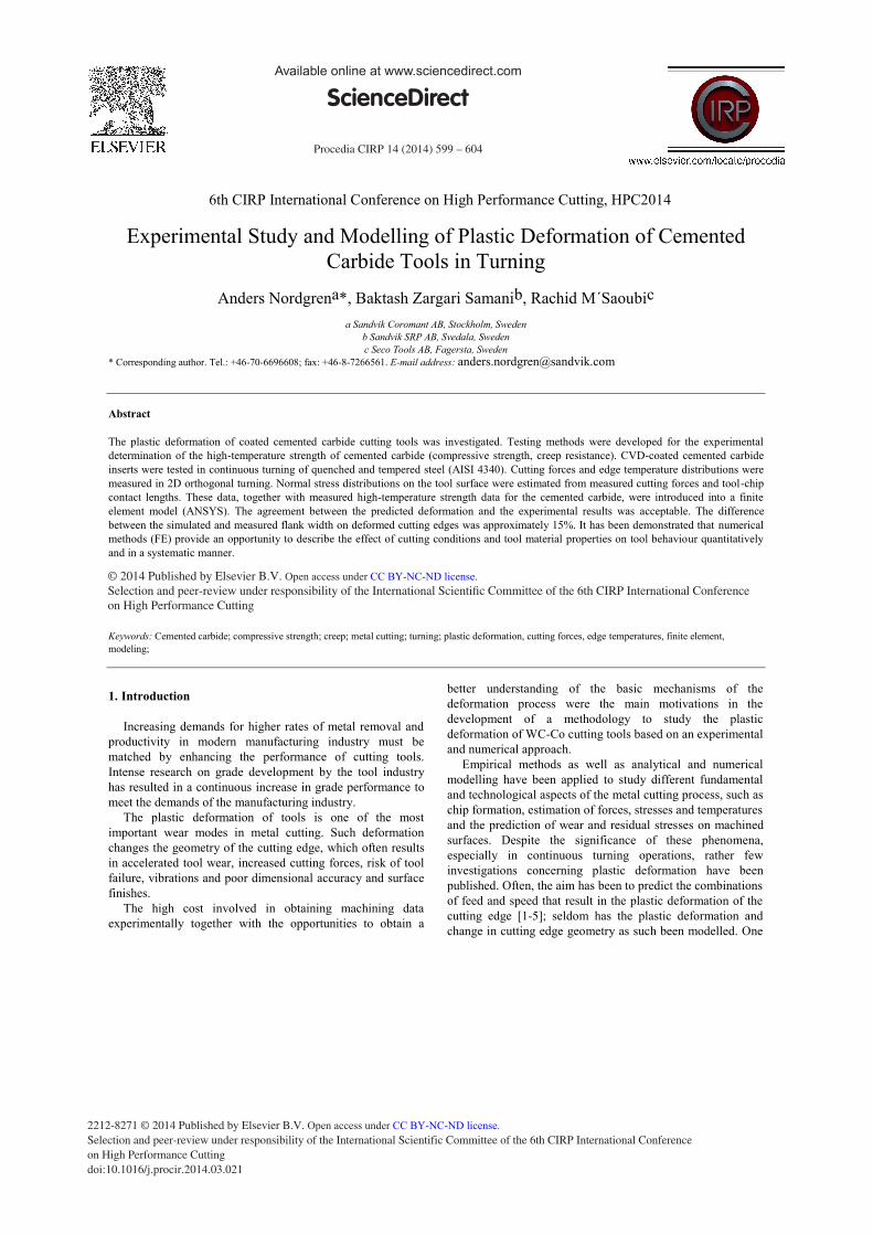
The workpiece material, cutting data and insert style were selected such that plastic deformation was the dominant wear mode and a relatively even distribution of edge deformation along the main cutting edge and tool nose was obtained. However, in this type of turning operation, completely even deformation along the cutting edge is not possible to achieve, and an increase in deformation from the depth of cut, along the edge, towards the tools nose is unavoidable. Figure 1 shows an example of a deformed cutting edge obtained from the turning tests.
Fig. 1. Flank view of a deformed cutting edge (flank land 0.38mm).
The quenched and tempered AISI4340 steel was machinability treated, i.e., the steel featured an inclusion pattern designed for increased machinability (to decrease tool wear and improve chip flow). The choice of workpiece material contributed to low tool wear and lack of interference from other wear phenomena during the tool deformation tests.
The cutting conditions were characterised by dry conditions (no coolant), high feed and a relatively high depth of cut. The insert styles used in the turning tests were TNMA220416 (rake angle -6o, clearance angle 6o) and TPUN220416 (rake angle +5o, clearance angle 6o), both insert styles with a flat rake face. Because the edge radius is known to affect the deformation of tools, inserts with a measured edge radius within a narrow range, approximately 40 μm, were used in the experiments.
During the turning tests, the machining was interrupted and the width of the flank land was measured every 30 seconds using a light optical stereo microscope. The measurements included both the flank land resulting from bulging of the tool material towards the workpiece surface as well the accompanying depression of the rake. The turning was
601 Anders Nordgren et al. / Procedia CIRP 14 ( 2014 ) 599 – 604
stopped when the measured value exceeded 0.5 mm. The experimental results are presented in Tables 2-4.
Table 2. Composition (wt%), steel AISI 4340.
C% Si% Mn% P% S% Cr% Ni% Mo%
0.37 0.28 0.64 0.007 0.027 1.54 1.43 0.16
Table 3. Properties, steel AISI 4340.
Hardness HBN YTS [MPa] UTS [MPa]
290 810-880 950-1010
Table 4. Turning test data.
Cutting speed [m/min]
Feed [mm/rev]
Depth of cut [mm]
Coolant Tool life criterion
200 0.5 3.5 No Flank land width 0.5mm
2.4. Measurement of cutting forces
The cutting forces were measured in both the longitudinal and orthogonal cutting directions using a Kistler type 5019A three-component force sensor. The force measurements were performed over the speed range 155-200 m/min for both the TNMA and TPUN inserts and on new and worn inserts, which were also subsequently used for temperature measurement.
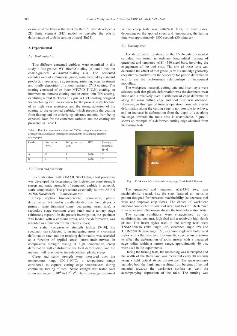
2.5. Measurement of tool temperature distributions
The tool temperature distribution was measured during the orthogonal cutting of workpiece tube specimens using the IR-CCD technique and the set-up developed in a previous investigation [11]. The present CCD-sensor-based near-infrared (850-1100 nm) imaging technique covers a temperature range of 500°C-1000°C, and the suitable calibration of this method enables the measurement of the tool temperature with reasonably good accuracy ( 10-15 C) and spatial resolution ( 4.5 m).
Fig. 2. Set-up for temperature measurement.
The inserts were ground and polished on their lateral face prior to cutting and temperature measurements to facilitate the observation the cutting zone. Only short-duration tests ( 15 s) were carried out to limit the problems that could arise from the oxidation of the tool surface, which may become
significant at longer cutting times. The cutting time chosen was, however, sufficient to reach the thermal balance in the region of the cutting zone close to the tool edge corresponding to the temperature range investigated. The typical set-up used for the temperature measurements is shown in Figure 2.
3. Results
3.1. High-temperature strength
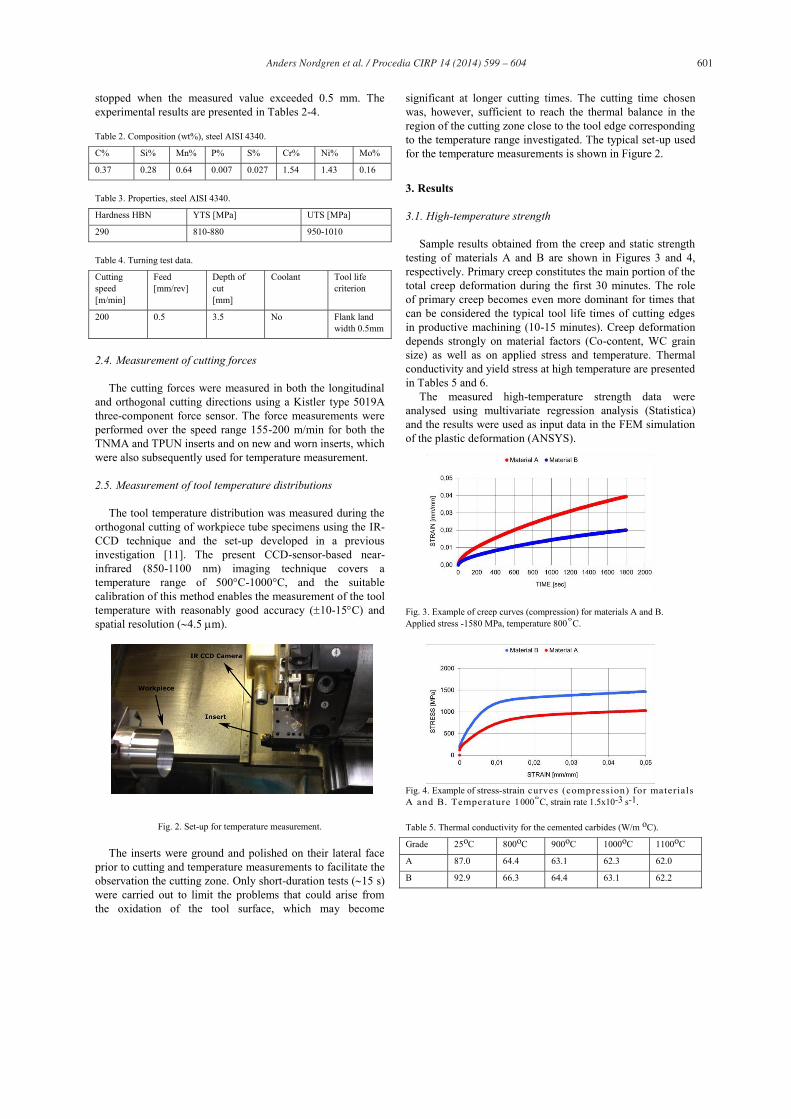
Sample results obtained from the creep and static strength testing of materials A and B are shown in Figures 3 and 4, respectively. Primary creep constitutes the main portion of the total creep deformation during the first 30 minutes. The role of primary creep becomes even more dominant for times that can be considered the typical tool life times of cutting edges in productive machining (10-15 minutes). Creep deformation depends strongly on material factors (Co-content, WC grain size) as well as on applied stress and temperature. Thermal conductivity and yield stress at high temperature are presented in Tables 5 and 6.
The measured high-temperature strength data were analysed using multivariate regression analysis (Statistica) and the results were used as input data in the FEM simulation of the plastic deformation (ANSYS).
Fig. 3. Example of creep curves (compression) for materials A and B. Applied stress -1580 MPa, temperature 800◦C.
Fig. 4. Example of stress-strain curves (compression) for materials A and B. Temperature 1000◦C, strain rate 1.5x10⁻³ s-1.
Table 5. Thermal conductivity for the cemented carbides (W/m oC).
Grade 25oC 800oC 900oC 1000oC 1100oC
A 87.0 64.4 63.1 62.3 62.0
B 92.9 66.3 64.4 63.1 62.2
602 Anders Nordgren et al. / Procedia CIRP 14 ( 2014 ) 599 – 604
Table 6. Yield stress for the cemented carbides (MPa).
Grade 25oC 800oC 900oC 1000oC 1100oC
A 4700 1780 1280 770 190
B 4600 2060 1640 1170 490
3.2. Turning tests
Figure 5 shows the results obtained from the turning tests of the two coated grades A and B in insert styles TNMA and TPUN. Grade A, based on the WC-10wt%Co-cemented carbide, clearly displays a much lower resistance against plastic deformation than grade B: the tool life was 1 minute or less. Grade B, based on the WC-6wt%Co material, displayed a tool life longer than 4 minutes. For both tool grades, the negative TNMA inserts displayed more deformation than the positive, more easily cut TPUN inserts.
The coating was subjected to wear to some extent during the turning test, but in the present investigation, the wear of the coating can be considered to have been insignificant; the main part of the coating was intact and still attached to the cemented carbide substrate, even after the severe deformation of the underlying cemented carbide. This was confirmed by scanning electron microscopy.
Fig. 5. Measured tool deformation vs cutting time.
3.3. Measured cutting forces
The cutting force measurements showed lower cutting forces for the positive TPUN inserts compared to the negative TNMA inserts, which was true especially for the feed force and when a flank land had developed due to deformation of the cutting edge (Figure 6).
Fig. 6. Measured cutting forces vs flank land width for different insert styles (grade B).
The effect of cutting speed in the range 155-200 m/min on the measured cutting forces was weak; a tendency for the cutting force to decrease with increasing cutting speed and thus increasing temperature in the cutting zone could be distinguished. Similarly, tool grade showed no significant effect: the measured forces were practically equal for both grades A and B.
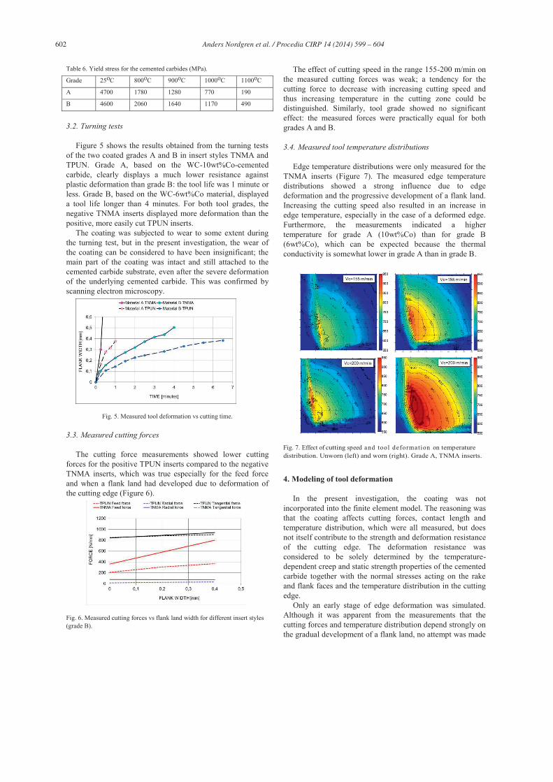
3.4. Measured tool temperature distributions
Edge temperature distributions were only measured for the TNMA inserts (Figure 7). The measured edge temperature distributions showed a strong influence due to edge deformation and the progressive development of a flank land. Increasing the cutting speed also resulted in an increase in edge temperature, especially in the case of a deformed edge. Furthermore, the measurements indicated a higher temperature for grade A (10wt%Co) than for grade B (6wt%Co), which can be expected because the thermal conductivity is somewhat lower in grade A than in grade B.
Fig. 7. Effect of cutting speed and tool deformation on temperature distribution. Unworn (left) and worn (right). Grade A, TNMA inserts.
4. Modeling of tool deformation
In the present investigation, the coating was not incorporated into the finite element model. The reasoning was that the coating affects cutting forces, contact length and temperature distribution, which were all measured, but does not itself contribute to the strength and deformation resistance of the cutting edge. The deformation resistance was considered to be solely determined by the temperature-dependent creep and static strength properties of the cemented carbide together with the normal stresses acting on the rake and flank faces and the temperature distribution in the cutting edge.
Only an early stage of edge deformation was simulated. Although it was apparent from the measurements that the cutting forces and temperature distribution depend strongly on the gradual development of a flank land, no attempt was made
603 Anders Nordgren et al. / Procedia CIRP 14 ( 2014 ) 599 – 604
to update the boundary conditions and to simulate the progress of edge deformation. Because tool temperature distributions were not measured for TPUN, only TNMA was included in the FE simulation.
4.1. Estimation of contact stress distributions
The cutting force components were separated according to the procedure described in [5], and the normal stress distribution on the rake face was estimated using the friction model suggested in [12]. The cutting force component normal to the rake face was distributed across the tool-chip contact length on the rake face according to equation (1).
n
totmN c
xx 1*)( (1)
where N is the normal stress, m is the normal stress at the edge line, n is an exponent, ctot is the total tool-chip contact length and x is the distance from the cutting edge line, in the chip flow direction. In the present investigation, the exponent n=1.64 (experimentally determined value for AISI4340 [12]), and ctot=0.72 mm (measured on used inserts) (Figure 8). The value of m was adjusted such that the estimated cutting force became equal to the measured value.
Fig. 8. Estimated normal stress distribution along the rake.
Essentially the same procedure used to separate the forces and the distribution of the normal stress was applied for the flank. The normal force acting on the flank land was separated from the total feed force based on a measurement of the feed force for different feeds. A linear relationship was obtained. The measured feed force was viewed as consisting of two parts: one contribution from chip formation and friction and one from the normal force acting on the tool flank.
The intersection with the y-axis in Figure 9 at zero feed and zero chip thickness was used as a measure of the normal force acting on the flank, whereas the additional feed force for feeds greater than zero was considered to be due to chip formation and friction work. The effect of tool radius was not accounted for. Minor effect was expected due to the high feed used in the turning tests.
Fig. 9. Separation of feed force components.
4.2. FE-analysis
Finite element analysis was carried out as a 2D, plane-stress, nonlinear static simulation in ANSYS. A higher-order, 2D triangular element (PLANE183) was used, an element with plasticity, hyper elasticity, creep, stress stiffening, large deflection and large strain capabilities. Constraints on the non-cutting sides of the tool model were applied to prevent any rigid-body motion.
The estimated normal stress distributions on the rake and flank faces, together with the measured temperature field in the tool, were applied (Figures 10 and 11).
Fig. 10. Applied pressure along the rake and flank.
Because the effect of grade composition on the measured cutting forces (unworn tool) and measured temperature was relatively weak, the same normal stress and temperature distributions were used for both grades A and B.
All necessary material property data for the cemented carbides (elastic modulus, high-temperature compressive strength) were gathered from the Sandvik hard material database and imported into ANSYS. The creep behaviour of the cemented carbides was described using a generalised time hardening model (primary creep).
604 Anders Nordgren et al. / Procedia CIRP 14 ( 2014 ) 599 – 604
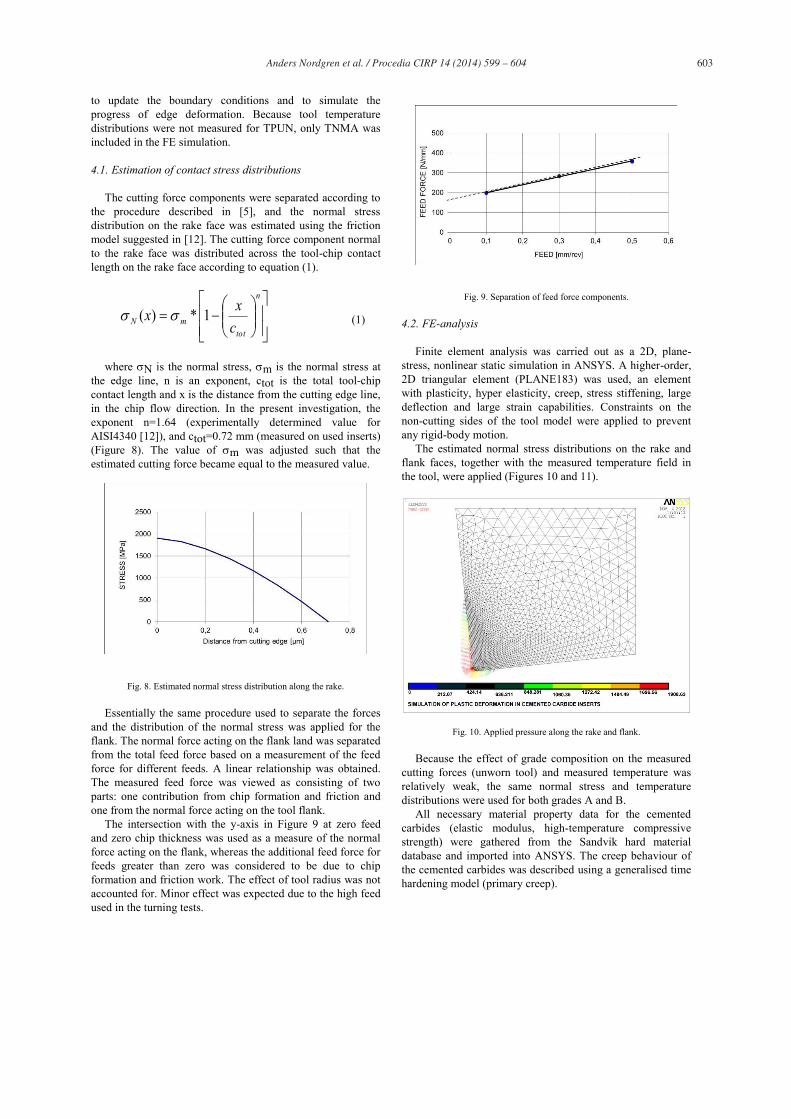
Fig. 11. Temperature distribution inside the tool.
4.3. Comparison with experimental results
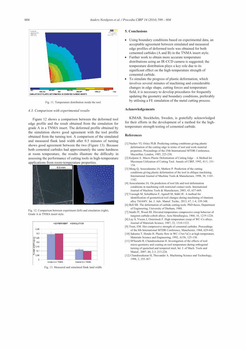
Figure 12 shows a comparison between the deformed tool edge profile and the result obtained from the simulation for grade A in a TNMA insert. The deformed profile obtained by the simulation shows good agreement with the tool profile obtained from the turning test. A comparison of the simulated and measured flank land width after 0.5 minutes of turning shows good agreement between the two (Figure 13). Because both cemented carbides had approximately the same hardness at room temperature, the results illustrate the difficulty in assessing the performance of cutting tools in high-temperature applications from room-temperature properties.
Fig. 12. Comparison between experiment (left) and simulation (right). Grade A in TNMA insert style.
Fig. 13. Measured and simulated flank land width.
5. Conclusions
Using boundary conditions based on experimental data, an acceptable agreement between simulated and measured edge profiles of deformed tools was obtained for both cemented carbides (A and B) in the TNMA insert style.
Further work to obtain more accurate temperature distributions using an IR-CCD camera is suggested; the temperature distribution plays a key role due to its significant effect on the high-temperature strength of cemented carbide.
To simulate the progress of plastic deformation, which involves several minutes of machining and considerable changes in edge shape, cutting forces and temperature field, it is necessary to develop procedures for frequently updating the geometry and boundary conditions, preferably by utilising a FE simulation of the metal cutting process.
Acknowledgements
KIMAB, Stockholm, Sweden, is gratefully acknowledged for their efforts in the development of a method for the high-temperature strength testing of cemented carbide.
References
[1] Nachev VI, Oxley PLB. Predicting cutting conditions giving plastic deformation of the cutting edge in terms of tool and work material properties. Proceedings of the 25th International MTDR Conference, Macmillan, London, 1985, 225-230.
[2] Kuljanic E. Macro Plastic Deformation of Cutting Edge – A Method for Maximum Utilization of Cutting Tool. Annals of CIRP, 1992, 41/1, 151-154.
[3] Meng Q, Arsecularatne JA, Mathew P. Prediction of the cutting conditions giving plastic deformation of the tool in oblique machining. International Journal of Machine Tools & Manufacture, 1998, 38, 1165-1182.
[4] Arsecularatne JA. On prediction of tool life and tool deformation conditions in machining with restricted contact tools. International Journal of Machine Tools & Manufacture, 2003, 43, 657-669.
[5] Vosough M, Schultheiss F, Agmell M, Ståhl JE. A method for identification of geometrical tool changes during machining of titanium alloy Ti6Al4V. Int. J. Adv. Manuf. Techn., 2013, 67, 1-4, 339-348.
[6] Bell SB. The deformation of carbide cutting tools. PhD thesis, Department of Engineering, University of Durham, 1988.
[7] Smith JT, Wood JD. Elevated temperature compressive creep behavior of tungsten carbide-cobolt alloys. Acta Metallurgica, 1968, 16, 1219-1226.
[8] Lay S, Vicens J, Osterstock F. High temperature creep of WC-Co alloys. Journal of Materials Science, 1987, 22, 1310-1322.
[9] Trent, EM. Hot compressive strength of cemented carbides. Proceedings of the 8th International MTDR Conference, Manchester, 1968, 629-642.
[10] Sakuma T, Hondo H. Plastic flow in WC-13wt.%Co at high temperature. Materials Science and Engineering, 1992, A156, 125-130.
[11] M'Saoubi R, Chandrasekaran H. Investigation of the effects of tool micro-geometry and coating on tool temperature during orthogonal turning of quenched and tempered steel, Int. J. of Mach. Tools and Manuf., 2007, 44, 2-3, 213-224.
[12] Chandrasekaran H, Thuvander A. Machining Science and Technology, 1998, 2, 355-367.
Top Related