


Languages
Pages
Legal

Examining Possible CCS Deployment Pathways:
Onshore and Offshore (FWP-1022464)
Timothy GrantDOE/NETL Energy Systems Analysis Team
U.S. Department of Energy
National Energy Technology Laboratory2021 Carbon Management and Oil and Gas Research Project Review Meeting
Carbon StorageAugust 4-11, 2021
2
Disclaimer
These studies were funded by the Department of Energy, National Energy Technology
Laboratory an agency of the United States Government, through a support contract. Neither
the United States Government nor any agency thereof, nor any of its employees, nor the
support contractor, nor any of their employees, makes any warranty, expressor implied, or
assumes any legal liability or responsibility for the accuracy, completeness, or usefulness of any
information, apparatus, product, or process disclosed, or represents that its use would not
infringe privately owned rights. Reference herein to any specific commercial product, process, or
service by trade name, trademark, manufacturer, or otherwise does not necessarily constitute or
imply its endorsement, recommendation, or favoring by the United States Government or any
agency thereof. The views and opinions of authors expressed herein do not necessarily state or
reflect those of the United States Government or any agency thereof.
All images in this presentation were created by NETL, unless otherwise noted.

3
CCS Deployment Challenges and Paths ForwardWhat factors serve as barriers inhibiting
CCS deployment?
• Cost and financial incentives are required to mitigate economic barriers and enable widespread CCS deployment; particularly
given disaggregated business models across CCSS value chains
• Multi-faceted analysis of economics, infrastructure, and geology is required to comprehend and stimulate active and
broad market for CCS
• Absence of documented safety and environmental regulations in offshore federal waters for storage is limiting offshore CCS
attractiveness
• Balance supply chain incentives are required to support operators and incentivize stakeholders
• Higher purity CO2 sources (NG processing, hydrogen production, and many ethanol production) provide for lower cost
of capture and first-mover candidates
• Proximity to high quality geologic storage sites where data is available, enabling site evaluation at lower cost, cheaper transport,
and more effective and affordable storage operations
• Economically favorable financial incentives for capturing and storage CO2
• Ability to enable effective integration of diverse source types
with CO2 transport and storage options across CCS value chain
What factors serve as enablers that promote CCS deployment?
Enabling attributes of CCS Projects. Source: Global Status of CCS 2020

4
Presentation Focus and Agenda
Analysis Discussed Objectives
Basin-scale CO2 storage modeling
Analysis of CO2 plume and pressure evolution behavior to inform basin management strategies and
operational decision making
Assessment of storage complex spacing to prevent pressure interference among projects
Onshore CO2 EOR
Nation-wide volumetric estimation of CO2 storage capacity and incremental oil recovery via CO2 EOR
Identification of impactful geologic, economic, and design parameters that most affect the performance of
CO2 EOR
Offshore storage pilot project
Identification of technical, economic, and geologic requirements for offshore CO2 pilot in Gulf of Mexico
(GoM)
Identification of regulatory gaps and economic challenges in offshore CCS environment to utilize single-lease
owned storage site away from population
Financial aspects (45Q tax credit)
Identification of financial gaps onshore and offshore, and potential configuration of operation of CCS
operator and investor partnership
Assessment of optimal tax credit monetization opportunities to help bridge financial gaps
NETL’s SSAE portfolio of carbon storage analyses aims to generate relevant models, tools, data, and studies that
address challenges to CCS deployment and inform industry, regulatory, academic, and public stakeholders on CO2
storage performance, associated cost drivers, and potential CCS business case viability and/or limitations.

5
Basin-Scale Modeling - Overview
Objectives:
1. Model and analyze multiple CO2 projects
at sedimentary basin scale
2. Model occurrence of multiple reservoirs
within sedimentary basin
3. Analyze interaction of these CO2 storage
operations with respect to areal extent of
CO2 plume and associated pressure front
that defines AoR per Class VI regulations
Methodology:
• Using TOUGH3-ECO2M simulator
• Starting analysis from project scale, rather
than basin scale
• Building reservoir model using publicly
available data on reservoir and fluid
properties
CO2 saturation1 Pressure extent2
1Teletzke, G., Palmer, J., Drueppel, E., Sullivan, M. B., Hood, K., Dasari, G., & Shipman, G. (2018, October). Evaluation of Practicable Subsurface CO2 Storage Capacity and Potential CO2
Transportation Networks, Onshore North America. In 14th Greenhouse Gas Control Technologies Conference Melbourne (pp. 21-26).2Birkholzer, J. T., & Zhou, Q. (2009). Basin-scale hydrogeologic impacts of CO2 storage: Capacity and regulatory implications. International Journal of Greenhouse Gas Control, 3(6), 745-756.
Parameter (Our Model) Unit Value
Permeability md 20
Porosity % 10
Target/Saline Formation Thickness ft 656
Perforation Interval - Entire target thickness

6
Modeling Results: CO2 Plume with 1 Injector
• Radius of CO2 plume
o Approximately 2 km at end
of 30-yr injection
o Approximately 2 km at end
of 50-yr PISC
• Radius of CO2 plume does
not significantly change during
PISC
o CO2 vertical distribution
takes place during PISC,
which increases overall CO2
saturation in top portion of
target formation
• Well spacing to prevent CO2
plume interference should be
larger than 4 km (for baseline
case)
End of 30-yr injection
End of 50-yr PISC
Side View
CO2 Saturation
(decimal)
CO2 Saturation
(decimal)

7
Modeling Results: Pressure Plume with 1 Injector
Pressure Difference
(End of 30-yr Injection)
Pressure Difference
(End of 50-yr PISC)
Well spacing to avoid pressure interference is much larger (>10 km) than the well spacing required to avoid CO2 plume
interference (2-3 km)
Pressure
Difference
(compared to
ambient pressure)
(psi)
Maximum Radius of Pressure
Difference
(km)
End of 30-year
InjectionEnd of 50-yr PISC
0.1 95 154
1 71 113
10 45 62
100 14None (max of 40
psi at 1 km)
Pressure propagates beyond CO2 plume
Aerial View

8
Next Steps: Sensitivity on Geologic Parameters and Well Spacing
• Sensitivity on geologic parameters:
o Boundary condition at the top of seal
o Boundary condition at the lateral (potential
neighboring basin)
o Boundary condition at the top and lateral end
combined
o Seal permeability
o Target formation permeability
o Target formation compressibility
o Seal compressibility
o Target formation porosity
o Target formation thickness
5 km 10 km 20 km 40 km 80 km 125 km
Sensitivity on Well Spacing

9
Onshore CO2 EOR - Overview
• CO2 EOR is established, safe,
and economically-viable
approach for U.S.
decarbonization
• NETL has assessed CO2 EOR
“size of the prize” in contiguous
United States for miscible water
alternating gas CO2 EOR
• Objectives:
o Assess onshore U.S. CO2 EOR
resource capacity (CO2 storage
and incremental oil production)
o Perform trend analyses on
results and sensitivity analysis
on CO2 EOR Evaluation
System used (schematic on the
right)
FE/NETL Onshore CO2 EOR Evaluation System Flowchart

10
Onshore CO2 EOR Results
• Technically feasible CO2 EOR in contiguous United States (at oil prices
< $1,000/STB when CO2 cost is = $30/t) could store over 19 Gt of
CO2 and could produce over 49 BSTB of incremental oil
• Takeaways:
o 81% of CO2 EOR resource capacity is economically feasible (at oil prices
<$100/STB), concentrated in 34% of the technically feasible oilfields
o Approximately 16 Gt of CO2 storage and 40 BSTB of incremental oil
production is economic
• CO2 EOR estimates using CO2 EOR Evaluation System are most
sensitive to uncertainties in reservoir size; conformance; new well drilling
and associated CAPEX
Cost Supply Curve for Economic CO2 EOR
Economic CO2 Storage Capacity by State and Basin from CO2 EOR
TXLA
CA
San
Joaquin
Permian
Western
Gulf
Onshore interior
salt basins
Over 75% of economic CO2 EOR
resource capacity is concentrated in 4
basins over 3 states
(labeled in figure to left)

11
Challenges to Offshore Storage in GOM3,4Advantages to Offshore Storage in GOM3,4
Offshore CO2 Storage - Overview
➢ High costs relative to onshore
➢ Lack of accurate / current cost data for O&G equipment
➢ Compatibility of O&G infrastructure with
➢ Source-to-sink matching challenges:
• Disparity in the types and location of onshore CO2
sources
• Source-specific proximity to potential sites with diverse
geologic conditions offshore
• Multitude of O&G infrastructure in place that could
potentially be repurposed for CCS
• Potential preference for onshore storage
In United States, an enormous opportunity exists for capturing CO2 from sources
onshore and deploying CO2 storage offshore in the Gulf of Mexico (GOM)
✓ Supplement to onshore storage options
✓ Sites located away from populated areas
✓ Reduced risk to USDWs
✓ O&G infrastructure in place to potentially reuse
✓ Proximity to industrialized zones on coastline
✓ Single entity (state or federal) pore space owner
3 Vidas, H., Hugman, B., Chikkatur, A., and Venkatesh, B. 2012. Analysis of the Costs and Benefits of CO₂ Sequestration on the U.S. Outer Continental Shelf .. ICF International. Fairfax, Virginia4 Schrag, D. 2009. Storage of Carbon Dioxide in Offshore Sediments. Science. Vol. 325., Issue 5948, pp. 1658 -1659.

12
Multi-Criteria Study for CCS Site Screening
• 14 criteria from publicly available geographic information system (GIS) layers utilized and
aggregated over 2,559 spatially balanced points across the study area using NETL's
Cumulative Spatial Impact Layers™ (CSIL) GIS tool
• Criteria were weighted by qualitative expert opinion relative to their perceived importance to
given scenarios. – the output of combined criteria values and weights enables regional CO2
storage suitability differentiation
Scenario 3: Long-term storage prioritizing
reuse of existing infrastructure
• Due to highly flexible methodology, new maps can be easily generated by adjusting criteria
weights based on new project goals
• Pending submission of manuscript to the International Journal of Greenhouse Gas Control
Scenario Description Location of High-Ranking Regions
1Long-term storage with emphasis
on geologic suitability
Off the Louisiana coast and extending to mid-
continental shelf
2EOR with emphasis on maximum
oil return
More sporadic but some clusters formed off coast of
Texas near Corpus Christi
3Long-term storage prioritizing
reuse of existing infrastructure
Offshore Louisiana near continental shelf edge (e.g.,
approximately 100 miles offshore from Lake Charles)
4EOR with emphasis on reuse of
existing infrastructure
Along Louisiana coastline, some located near shore but
mostly concentrated near continental slope
Scenario 1: Favorable storage sites with
emphasis on geologic suitability

13
Offshore CO2 Storage Pilot Project Overview
Criteria Consideration Criteria Status (In Development)
1-Project type Storage formation Saline storage
2-Pilot objectives Research objectives
• Evaluate two different project considerations where CO2 would be captured from onshore sources and piped offshore for long-term storage in geologic formations in GoM
• Gain insight on potential cost (capital and operating) and equipment needs when considering offshore CO2 storage operations in GoM at pilot-scale
• Two pilot project considerations could be reasonably similar in terms of water depth and transport mechanism and would reuse existing top-side offshore infrastructure
• Two pilot considerations would vary in their locations in GoM, distance from shore, geologic conditions, and federal vs. state jurisdiction• Cost and equipment considerations, influenced mostly by differences in geologic conditions and distance from shore in this case, will be
compared between each pilot project type
3-OperationsRisk preference Least cost risk should coincide with least environmental riskInjection rate Demonstration Scale - (at least 0.5 million metric tons per year [Mt/yr])Operation duration Medium-term (12-year) to capture full 45Q benefit
4-GeologyJurisdiction/water depth/proximity to land
Configuration #1: state waters (Texas)Configuration #2: federal waters (not restricted to Texas, but still shallow waters)
5-Infrastructure
Offshore infrastructure approach Reuse existing infrastructureOffshore CO2 transportation PipelineOffshore injection site PlatformOnshore CO2 source Agnostic to onshore CO2 source(s); study constrained to the coastal offtake hub, pipeline transport, and storage site
6-Monitoring
CO2 Plume
In development – open to feedbackPressure (in and above-zone)Microseismic
GeochemicalWell Integrity
7-PISCDuration
In development – open to feedbackMonitoring / frequencyDecommissioning
Working toward developing technical (infrastructure, equipment, and monitoring) and geologic criteria
needed for an initial CO2 storage site in the Gulf of Mexico and evaluate the cost magnitude of pilot project
2 scenarios will be developed:
1. Texas state waters2. Federal waters

14
Leveraging Existing Multi-Criteria Tool for Pilot Project
CSILTM and multi-criteria layering framework will be used to screen for high-priority
locations for offshore CO2 saline storage pilot based on pilot project criteria and attributes
Scenario “5”Offshore pilot project
Oil fields
Infrastructure
CO2 Storage
Shipping Routes
Multi-criteria layering framework Set of new weights
for pilot project
criteria
Highest Priority Pilot Project Areas• Evaluate existing infrastructure• Characterize geologic conditions• Build out infrastructure items and
costs with IHS Que$torTM
15
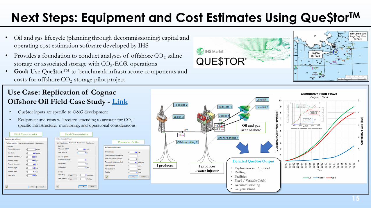
Next Steps: Equipment and Cost Estimates Using Que$torTM
Detailed Que$tor Output
• Exploration and Appraisal
• Drilling
• Facilities
• Fixed / Variable O&M
• Decommissioning
• CO2 emissions
Use Case: Replication of Cognac
Offshore Oil Field Case Study - Link
• Que$tor inputs are specific to O&G development
• Equipment and costs will require amending to account for CO2-
specific infrastructure, monitoring, and operational considerations
• Oil and gas lifecycle (planning through decommissioning) capital and
operating cost estimation software developed by IHS
• Provides a foundation to conduct analyses of offshore CO2 saline
storage or associated storage with CO2-EOR operations
• Goal: Use Que$torTM to benchmark infrastructure components and
costs for offshore CO2 storage pilot project

16
Financial Aspects of CCS - Overview
• Section 45Q tax credits (45Q) are available to qualified carbon capture projects to incentivize
CCS deployment
• NETL is working to develop capability to quantify impact of 45Q on carbon management
costs
o Assessing impact of 45Q on economic CCS project costs (45Q Impact Assessments)
o Developing model that honors IRS and U.S. Treasury guidance on 45Q and tax equity partnerships (45Q TEP Modeling)
• Integrating costs across CCS network, leveraging NETL’s resources and models for
o Capture: Cost and Performance Baselines for Fossil Energy Plants, Volume 1: Bituminous Coal and Natural Gas to Electricity; Cost of Capturing CO2 from Industrial Sources report
o Transport: FE/NETL CO2 Transport Cost Model (CO2_T_COM)
o Storage: FE/NETL Onshore CO2 Saline Storage Cost Model (CO2_S_COM)
• Develop capability to model complexities of tax equity partnerships
o FE/NETL 45Q Tax Credit Monetization Model (in development)

17
45Q Impact Assessments• NW Central U.S. 45Q Impact case study (unpublished) and CCS Finance Gap and SCC Tax study (Energies, 2021)5
• Accounted for basic tax equity partnership assumptions but did not account for monetization of non-45Q tax benefits (like asset depreciation and negative income)
• Results: $50/tCO2 45Q lowers CO2 management costs by ~$29-$34/tCO2 (2026$) but does not itself close finance gap (even with carbon emission penalties)
• Finance gap in these studies made up by increased price of produced commodity (i.e., electricity or cement)
• Detailed tax equity partnership modeling is warranted
WY SCPC
ND SCPC
SD CEMENT
RR1
MI2
LA1
MA01 $-
$50
$100
$150
$200
$250
$300
$350
SD Cement WY SCPC ND SCPC
LC
O-C
om
modity
(2018$ /
t C
O2)
$ / t CO2 - no CCS $ / t CO2 - CCS only $ / t CO2- CCS with 45Q
Levelized Cost of Commodity Required for Economic Scenarios
CCS Finance
Gapw/45Q: ~$160/t
45Q benefit: ~$30/t
CCS Finance
Gap w/o 45Q
NW Central U.S. 45Q Impact Case Study
45Q benefit accounting for non-45Q
benefits:~$42/t
5A. Steele, T. Warner, D. Vikara, A. Guinan, and P. Balash, “Comparative analysis of carbon capture and storage finance gaps and the social cost of carbon," Energies, vol. 14(11), 2987, 2021.

18
45Q Tax Equity Partnership (TEP) Modeling
• Previous NETL 45Q impact assessments used broad TEP assumptions and did
not account for non-45Q tax benefit monetization available through TEPs
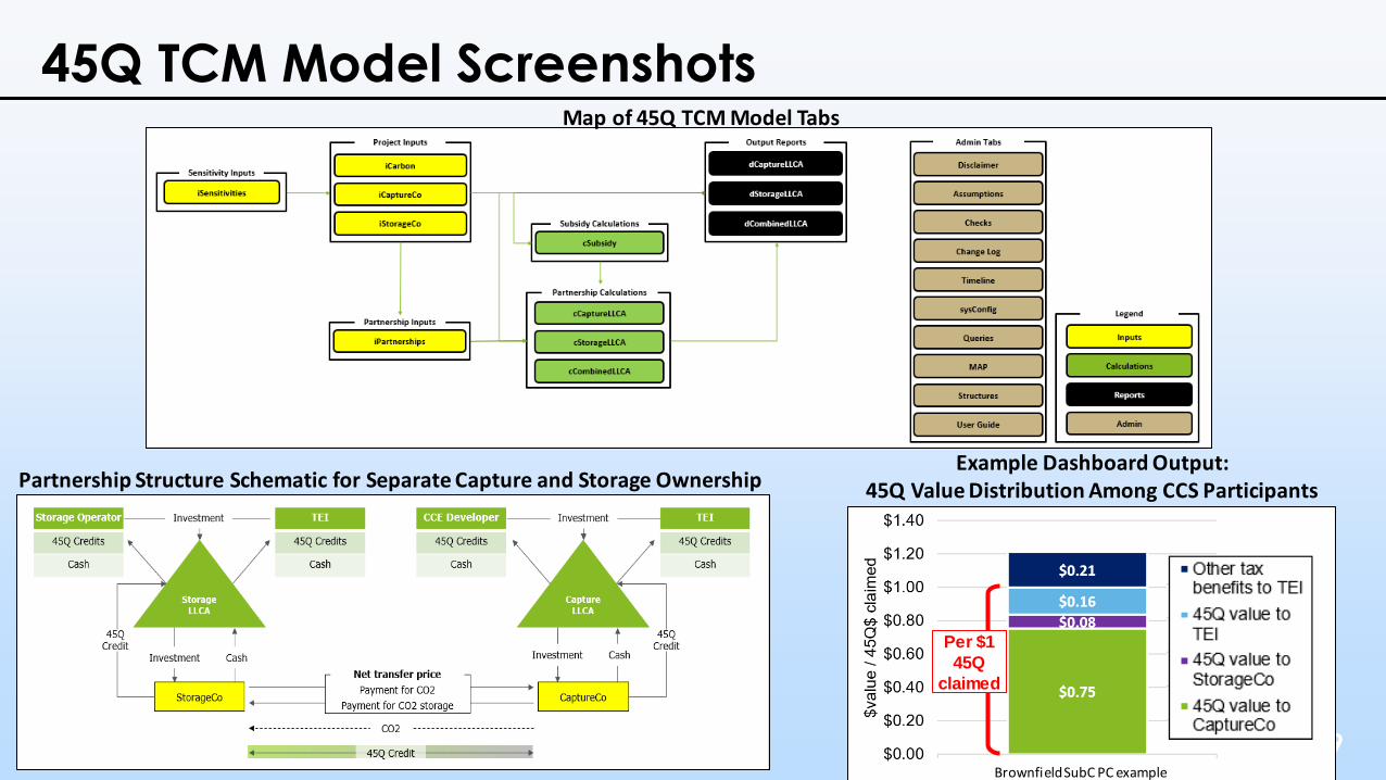
• This project has developed 45Q Tax Credit Monetization (TCM) model that:
o Demonstrates how 45Q value is distributed and monetized among CCS
participants within TEP
o Calculates how much subsidy (if any) is needed to make CCS project economic
• Current status: finalizing Excel®-based 45Q TCM Model and applying 45Q TCM
Model to onshore and offshore CCS project
19
45Q TCM Model Screenshots
Per $1
45Q
claimed
Map of 45Q TCM Model Tabs
Partnership Structure Schematic for Separate Capture and Storage OwnershipExample Dashboard Output:
45Q Value Distribution Among CCS Participants
Brownfield SubC PC example

20
45Q TCM Model Application
• Economic assessment of various scenarios on and offshore
o Aiding in expansion of CCS in GoM
• Utilize 45Q TCM Model for scenarios to:
o Determine optimal structure for monetization of CO2 storage/associated storage
project 45Q tax credits
• Building on previously developed supply chain model for exploratory analysis of
economics of CCS in GoM
o Reviewing barriers including CO2 storage regulations (local, state, and federal)

21
Conclusions
• Basin-scale modeling provides assessment of storage complex spacing to prevent CO2 plume and pressure interference. Analysis
on optimum well spacing provides insights to determination of AoR to inform regulatory stakeholders
• Onshore CO2 EOR analysis provides nation-wide volumetric estimation of CO2 storage capacity and incremental oil recovery
which can increase market interest for deploying CCS technology
• Offshore pilot project is unique CCS opportunity because it involves single-lease owner and project can be deployed away from
population areas. However, policies/regulations in offshore need further documented clarity to support offshore CCS deployment
• 45Q tax credit can help finance CCS projects but analysis suggests that 45Q tax credit alone might not be adequate to solve the
financial gap. Therefore, 45Q tax equity partnership modeling aims to assess distribution of monetization among CCS participants
and calculate required subsidy amount to make CCS project economic
NETL is aiming to further facilitate deployment of onshore and offshore CCS moving forward by extending existing
toolset capability, relevance, and follow-on analyses to coincide with ongoing technology maturation – helping to enable
launch of geologic carbon storage industry
Analytical models, tools, data, and analyses developed by NETL SSAE/collaborators provide extensive
portfolio of resources that can apprise stakeholders of both technical and economic aspects associated with
implementing commercial-scale CO2 storage projects

22
Acknowledgements
NETL Research & Innovation Center
Peter Balash – Acting Associate Director, Strategic Systems Analysis & Engineering (SSAE) Directorate
Luciane Cunha – Supervisor, Energy Systems Analysis Team (ESAT)
Mark McKoy – Carbon Storage Technology Manager
Justin Adder, NETL SubCLIN 202 Contracting Officer’s Representative
Donald Remson, NETL SubCLIN 205 Contracting Officer’s Representative
Angela Goodman, NETL Technical Project Monitor
David Morgan, NETL Technical Project Monitor
Chris Nichols, NETL Technical Project Monitor
Kelly Rose, NETL Technical Project Monitor
Marty Webler, BMS Technology Development & Integration Center
Mission Execution and Strategic Analysis (NETL Support Contractors)
Kolawole Bello
Allison Guinan
Amanda Harker-Steele
Arun Iyengar
Sam Levinson
Smriti Sharma
Alana Sheriff
Chung Yan Shih
Mazin Tarhoni
Derek Vikara
Travis Warner
Anna Wendt
Nur Wijaya
Connie Zaremsky
Research Support Services (NETL Support Contractors)Mohammad Foad Haeri Evgeniy Myshakin

23
Questions?

24
Resources and Recent Publications
MODELS
• FE/NETL CO2 Transport Cost Model
• FE/NETL CO2 Saline Storage Cost Model
• FE/NETL CO2 Prophet Cost Model
• FE/NETL Onshore CO2 EOR Cost Model
TOOLS
• NETL-developed Cumulative Spatial Impact Layers™ (CSIL) GIS tool:
• Literature
• Dataset
• TOUGH Multiphase Flow Simulator
PRODUCTS (Manuscripts)
A. Steele, T. Warner, D. Vikara, A. Guinan, and P. Balash, “Comparative analysis of carbon capture and storage finance gaps and the social cost of
carbon," Energies, vol. 14(11), 2987, 2021.
T. Grant, D. Morgan, A. Poe, J. Valenstein, R. Lawrence and J. Simpson, "Which reservoir for low cost capture, transportation, and storage?," Energy
Procedia, vol. 63, p. 2663 – 2682, 2014.
D. Vikara, C. Shih, S. Lin, A. Guinan, T. Grant, D. Morgan and D. Remson, "U.S. DOE’s economic approaches and resources for evaluating the cost of
implementing carbon capture, utilization, and storage (CCUS)," Journal of Sustainable Energy Engineering, vol. 5, no. 4, pp. 307-340, 2017.
T. Grant, A. Guinan, C. Shih, S. Lin, D. Vikara, D. Morgan and D. Remson, "Comparative analysis of transport and storage options from a CO2 source
perspective," International Journal of Greenhouse Gas Control, vol. 72, pp. 175-191, 2018.
D. Vikara, C. Shih, A. Guinan, S. Lin, A. Wendt, T. Grant and P. Balash, "Assessing Key Drivers Impacting the Cost to Deploy Integrated CO2 Capture,
Utilization, Transportation, and Storage (CCUS)," Proceedings of 36th USAEE/IAEE North American Conference: Evolving Energy Realities: Adapting to
What's Next, 2018.
Top Related