


Languages
Pages
Legal


EQ5 AC Drive Operations Manual
Document: TWMC-EQ5OM Revision: 001P0

EQ5 AC Drive Operations Manual
_______________________________________________________________________ TECO – Westinghouse Motor Company Compliance with UL
Preface Thank you for purchasing our EQ5 series inverter. This product is used to drive a 3-phase electric motor at variable speed. As incorrect use of this product may result in personal injury and/or property damage, please read all safety and operating instructions before using.
Safety Instructions
Please read this manual carefully before installing, connecting (wiring), operating, servicing, or inspecting the inverter. Also please familiarize yourself with all safety features before using the inverter. In this manual, safety messages are classified as follows:
Danger Improper operation may result in serious personal injury or death.
Caution Improper operation may result in slight to medium personal injury or property damage.
Situations more serious than those covered by CAUTION will depend on prevailing circumstances. Always follow instructions.
Instructions on use:
Danger • This inverter is designed to drive a 3-phase induction motor and is not suitable for a single-phase motor or
any other types, as fire may result. • This inverter may not be used (as is) as a component of a life-support system or other medical device
directly affecting the personal welfare of the user. • This inverter is manufactured under strict quality control standards. However, safety equipment must be
installed if the failure of this device may result in personal injury and/or property damage. • There is a risk of accident.
Instructions on installation:
Danger• Mount this inverter on an incombustible material such as metal. There is a risk of fire. • Do not place combustible or flammable material near this inverter, as fire may result.
Caution
• Do not hold or carry this inverter by the surface cover. Inverter may be dropped causing injury. • Ensure that the inverter and heat sink surfaces are kept free of foreign matter (lint, paper dust, small chips
of wood or metal, and dust), as fire or accident may result. • Do not install or operate a damaged inverter or an inverter with missing parts, as injury may result.

EQ5 AC Drive Operations Manual
_______________________________________________________________________ TECO – Westinghouse Motor Company Compliance with UL
Instructions on wiring:
Danger • Connect the inverter to power via a line-protection molded-case circuit breaker or fuse, otherwise fire may
result. • Always connect a ground wire, otherwise electric shock or fire may result. • A licensed specialist must perform the wiring, otherwise electric shock may result. • Turn off the power before starting the wiring, otherwise electric shock may result. • Wire the inverter after installation is complete, otherwise electric shock or injury may occur.
Caution
• Confirm that the phases and rated voltage of this product match those of the AC power supply, otherwise injury may result.
• Do not connect the AC power supply to the output terminals (U,V,and W), otherwise injury may result. • Do not connect a braking resistor directly to the DC terminals (P(+)and N(-)),otherwise fire may result. • Ensure that the noise generated by the inverter, motor, or wiring does not adversely affect peripheral
sensors and equipment, otherwise accident may result.
Instructions on operation:
Danger • Be sure to install the surface cover before turning on power (closed). Do not remove the cover while
power to the inverter is on. Otherwise electric shock may occur. • Do not operate switches with wet hands, otherwise electric shock may result. • When the retry function is selected, the inverter may restart automatically after tripping. Design the machine
to ensure personal safety in the event of restart. Accident may result. • When the torque limiting function is selected, operating conditions may differ from preset conditions
(acceleration/deceleration time or speed). In this case, personal safety must be assured. Otherwise accident may result.
• As the STOP key is effective only when a function setting has been established, install an emergency switch independently, and when an operation via the external signal terminal is selected, the STOP key on the keypad panel will be disabled. Otherwise accident may result.
• As operations start suddenly if an alarm is reset with a running signal input, confirm that no running signal is input before resetting alarm. Otherwise accident may result.
• Do not touch inverter terminals when energized even if inverter has stopped. Otherwise electric shock may result.
Caution • Do not start or stop the inverter using the main circuit power. Failure may result. • Do not touch the heat sink or braking resistor because they can be extremely hot. Burns may result. • Carefully check the performance of motor or machine before operating at high speed. Injury may result. • Do not use the inverter braking function for mechanical holding. Otherwise injury may result.
EQ5 AC Drive Operations Manual
_______________________________________________________________________ TECO – Westinghouse Motor Company Compliance with UL
Instructions on maintenance, inspection, and replacement:
Danger • Wait a minimum of five minutes (30HP/CT, 40HP/VT or less) or ten minutes (40HP/CT, 50HP/VT or more)
after power has been turned off (open) before starting an inspection. (Also confirm that the charge lamp is off and that DC voltage between terminals P (+) and N (-) does not exceed 25V.) Otherwise electrical shock may result.
• Only authorized personnel should perform maintenance, inspection, and replacement operations.(Take off metal jewelry such as watches and rings and use insulated tools.) Otherwise electric shock or injury may result.
Instructions on disposal:
Caution • Treat as industrial waste when disposing it. Otherwise injury may result.
Other instructions:
Danger • Never modify the product. Otherwise electric shock or injury may result.

EQ5 AC Drive Operations Manual
_______________________________________________________________________ TECO – Westinghouse Motor Company Compliance with UL
Compliance with UL/cUL standards [Applicable to products with UL/cUL mark]
Caution Tightening torque and wire range: Refer to Table 2-3-5 in Section 2
Apply the following power supply specifications to the inverter:
Inverter Model Maximum input voltage Input source current EQ5 - 20P2 - N1 to EQ5 - 2032 - N1
AC240V Not more than 100,000A
EQ5 - 2040 - C to EQ5 - 2150 - C EQ5 - 40P5 - N1 to EQ5 - 4032 - N1
AC480V EQ5 - 4040 - C to EQ5 - 4800 - C
Caution * [CAUTION] Hazard of electrical shock. Disconnect incoming power before working on this control.
* [CAUTION] Dangerous voltage exists until charge light is off. * [WARNING] * More than one live parts inside the inverter. * Type1 “INDOOR USE ONLY”
The inverter is approved as a part used inside a panel. Install it inside a panel. * Suitable for use on a circuit capable of delivering not more than 100,000rms symmetrical amperes. * Use 60/75C copper wire only. * A Class2 circuit wired with class1 wire. * Field wiring connections must be made by a UL Listed and CSA Certified closed-loop terminal connector
sized for the wire gauge involved. Connector must be fixed using the crimp tool specified by the connector manufacturer.
* Connect the power supply to main power supply terminals via the Molded-case circuit breaker (MCCB) or a ground fault circuit interrupter (GFCI) to conform to the UL Listing Mark. (See Instruction Manual basic connection diagram Fig.2-3-1).
* When using auxiliary control-power input (R0, T0), connect as per Basic connection diagram Fig.2-3-1. * Solid state motor overload protection is provided in each model.
EQ5 AC Drive Operations Manual
_______________________________________________________________________ TECO – Westinghouse Motor Company Index
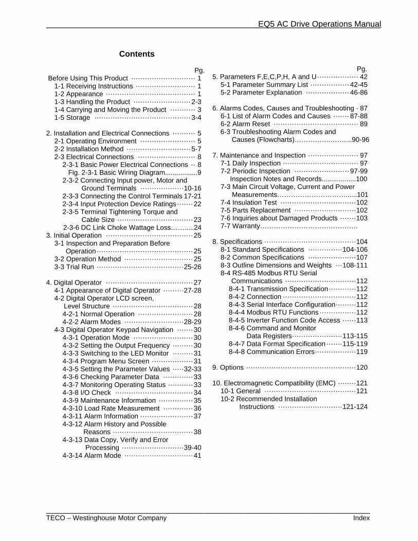
Contents Pg. Before Using This Product ···························· 1
1-1 Receiving Instructions ·························· 1 1-2 Appearance ······································· 1 1-3 Handling the Product ························· 2-3 1-4 Carrying and Moving the Product ··········· 3 1-5 Storage ·········································· 3-4
2. Installation and Electrical Connections ·········· 5
2-1 Operating Environment ························ 5 2-2 Installation Method ···························· 5-7 2-3 Electrical Connections ························· 8
2-3-1 Basic Power Electrical Connections ·· 8 Fig. 2-3-1 Basic Wiring Diagram.................9 2-3-2 Connecting Input power, Motor and Ground Terminals ··················· 10-16 2-3-3 Connecting the Control Terminals 17-21 2-3-4 Input Protection Device Ratings ······· 22 2-3-5 Terminal Tightening Torque and Cable Size ································· 23
2-3-6 DC Link Choke Wattage Loss…….....24 3. Initial Operation ······································ 25
3-1 Inspection and Preparation Before Operation ·········································· 25 3-2 Operation Method ······························ 25 3-3 Trial Run ······································ 25-26
4. Digital Operator ······································ 27
4-1 Appearance of Digital Operator ········· 27-28 4-2 Digital Operator LCD screen, Level Structure ··································· 28
4-2-1 Normal Operation ························ 28 4-2-2 Alarm Modes ·························· 28-29
4-3 Digital Operator Keypad Navigation ······· 30 4-3-1 Operation Mode ·························· 30 4-3-2 Setting the Output Frequency ········· 30 4-3-3 Switching to the LED Monitor ········· 31 4-3-4 Program Menu Screen ·················· 31 4-3-5 Setting the Parameter Values ····· 32-33 4-3-6 Checking Parameter Data ············· 33 4-3-7 Monitoring Operating Status ··········· 33 4-3-8 I/O Check ·································· 34 4-3-9 Maintenance Information ··············· 35 4-3-10 Load Rate Measurement ············· 36 4-3-11 Alarm Information ······················· 37 4-3-12 Alarm History and Possible Reasons ··································· 38 4-3-13 Data Copy, Verify and Error Processing ··························· 39-40 4-3-14 Alarm Mode ······························ 41
Pg. 5. Parameters F,E,C,P,H, A and U ·················· 42
5-1 Parameter Summary List ················· 42-45 5-2 Parameter Explanation ··················· 46-86
6. Alarms Codes, Causes and Troubleshooting · 87
6-1 List of Alarm Codes and Causes ······· 87-88 6-2 Alarm Reset ····································· 89
6-3 Troubleshooting Alarm Codes and Causes (Flowcharts)………….….……...90-96
7. Maintenance and Inspection ······················ 97 7-1 Daily Inspection ································· 97 7-2 Periodic Inspection ························ 97-99 Inspection Notes and Records..................100 7-3 Main Circuit Voltage, Current and Power Measurements…………………………......101 7-4 Insulation Test ································· 102 7-5 Parts Replacement ··························· 102 7-6 Inquiries about Damaged Products ······· 103 7-7 Warranty…………………………………….
8. Specifications ········································ 104
8-1 Standard Specifications ··············· 104-106 8-2 Common Specifications ····················· 107 8-3 Outline Dimensions and Weights ··· 108-111 8-4 RS-485 Modbus RTU Serial
Communications ······························· 112 8-4-1 Transmission Specification ············ 112 8-4-2 Connection ································ 112 8-4-3 Serial Interface Configuration ········· 112 8-4-4 Modbus RTU Functions ················ 112 8-4-5 Inverter Function Code Access ······ 113 8-4-6 Command and Monitor
Data Registers······················ 113-115 8-4-7 Data Format Specification ······· 115-119 8-4-8 Communication Errors ·················· 119
9. Options ················································ 120 10. Electromagnetic Compatibility (EMC) ········ 121
10-1 General ········································ 121 10-2 Recommended Installation
Instructions ···························· 121-124
EQ5 AC Drive Operations Manual
_________________________________________________________________________ TECO – Westinghouse Motor Company Receiving and Handling 1
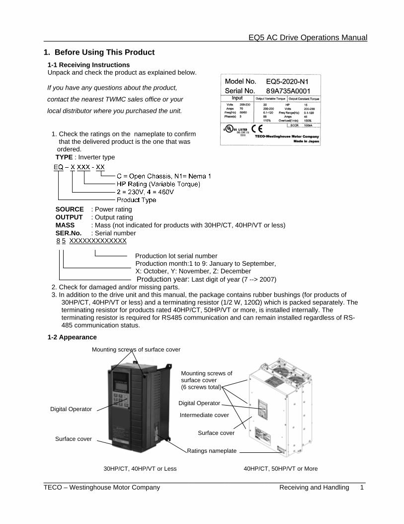
1. Before Using This Product 1-1 Receiving Instructions Unpack and check the product as explained below.
If you have any questions about the product,
contact the nearest TWMC sales office or your
local distributor where you purchased the unit.
1. Check the ratings on the nameplate to confirm that the delivered product is the one that was ordered.
TYPE : Inverter type
SOURCE : Power rating OUTPUT : Output rating MASS : Mass (not indicated for products with 30HP/CT, 40HP/VT or less) SER.No. : Serial number
8 5 XXXXXXXXXXXXX Production lot serial number
Production month:1 to 9: January to September, X: October, Y: November, Z: December Production year: Last digit of year (7 --> 2007)
2. Check for damaged and/or missing parts. 3. In addition to the drive unit and this manual, the package contains rubber bushings (for products of
30HP/CT, 40HP/VT or less) and a terminating resistor (1/2 W, 120Ω) which is packed separately. The terminating resistor for products rated 40HP/CT, 50HP/VT or more, is installed internally. The terminating resistor is required for RS485 communication and can remain installed regardless of RS-485 communication status.
1-2 Appearance
Mounting screws of surface cover
Digital Operator Digital Operator
Mounting screws of surface cover (6 screws total)
Ratings nameplate
Surface cover
Intermediate cover
Surface cover
30HP/CT, 40HP/VT or Less 40HP/CT, 50HP/VT or More
EQ5 AC Drive Operations Manual
_________________________________________________________________________ TECO – Westinghouse Motor Company Receiving and Handling 2
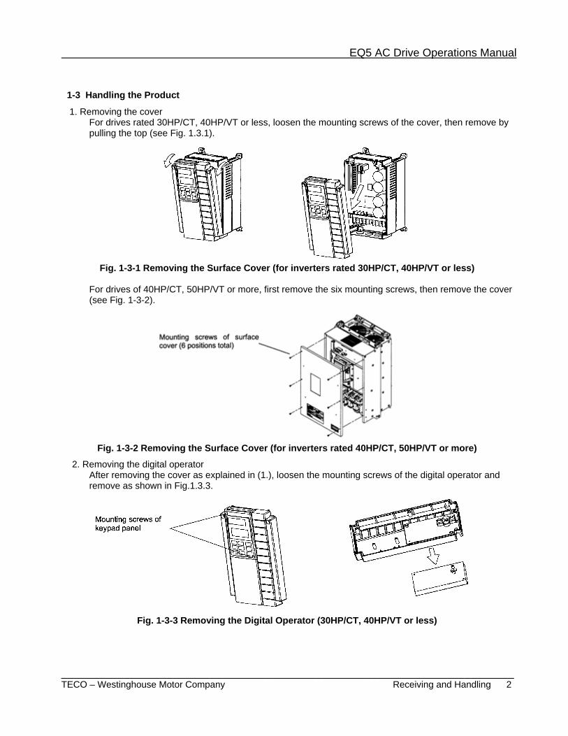
1-3 Handling the Product
1. Removing the cover For drives rated 30HP/CT, 40HP/VT or less, loosen the mounting screws of the cover, then remove by pulling the top (see Fig. 1.3.1).
Fig. 1-3-1 Removing the Surface Cover (for inverters rated 30HP/CT, 40HP/VT or less)
For drives of 40HP/CT, 50HP/VT or more, first remove the six mounting screws, then remove the cover (see Fig. 1-3-2).
Fig. 1-3-2 Removing the Surface Cover (for inverters rated 40HP/CT, 50HP/VT or more)
2. Removing the digital operator After removing the cover as explained in (1.), loosen the mounting screws of the digital operator and remove as shown in Fig.1.3.3.
Fig. 1-3-3 Removing the Digital Operator (30HP/CT, 40HP/VT or less)
EQ5 AC Drive Operations Manual
_________________________________________________________________________ TECO – Westinghouse Motor Company Receiving, Handling, and Storage 3
Temporary Storage
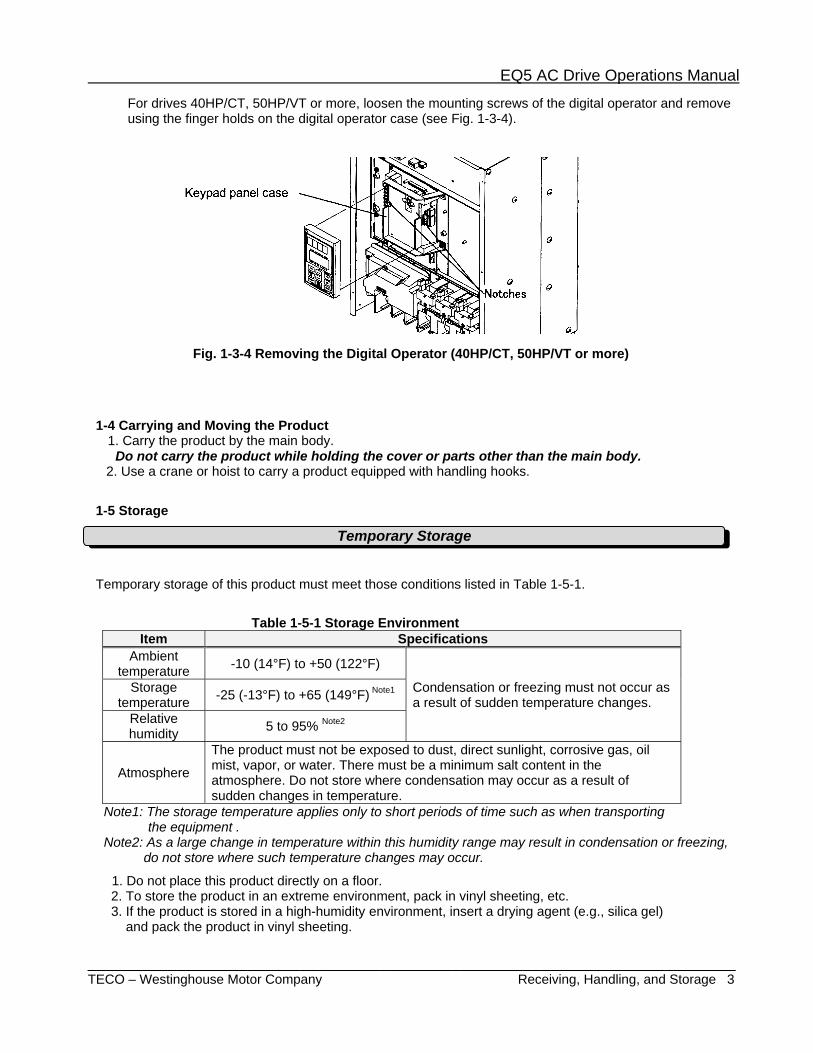
For drives 40HP/CT, 50HP/VT or more, loosen the mounting screws of the digital operator and remove using the finger holds on the digital operator case (see Fig. 1-3-4).
Fig. 1-3-4 Removing the Digital Operator (40HP/CT, 50HP/VT or more)
1-4 Carrying and Moving the Product
1. Carry the product by the main body. Do not carry the product while holding the cover or parts other than the main body.
2. Use a crane or hoist to carry a product equipped with handling hooks.
1-5 Storage
Temporary storage of this product must meet those conditions listed in Table 1-5-1.
Table 1-5-1 Storage Environment
Item Specifications Ambient
temperature -10 (14°F) to +50 (122°F)
Condensation or freezing must not occur as a result of sudden temperature changes.
Storage temperature -25 (-13°F) to +65 (149°F) Note1
Relative humidity 5 to 95% Note2
Atmosphere
The product must not be exposed to dust, direct sunlight, corrosive gas, oil mist, vapor, or water. There must be a minimum salt content in the atmosphere. Do not store where condensation may occur as a result of sudden changes in temperature.
Note1: The storage temperature applies only to short periods of time such as when transporting the equipment . Note2: As a large change in temperature within this humidity range may result in condensation or freezing,
do not store where such temperature changes may occur.
1. Do not place this product directly on a floor. 2. To store the product in an extreme environment, pack in vinyl sheeting, etc. 3. If the product is stored in a high-humidity environment, insert a drying agent (e.g., silica gel) and pack the product in vinyl sheeting.

EQ5 AC Drive Operations Manual
_________________________________________________________________________ TECO – Westinghouse Motor Company Receiving, Handling, and Storage 4
Long-term Storage
If the product is to be stored for an extended period of time after purchase, the method of storage depends primarily on storage location. The general long-term storage method is as follows:
1. The above conditions for temporary storage must be satisfied. When the storage period exceeds three months, the upper limit of ambient temperature must be reduced to 30º (86ºF) to prevent the deterioration of the electrolytic capacitors.
2. Pack the product thoroughly to eliminate exposure to moisture and include a drying agent to ensure a relative humidity of about 70% or less. 3. If the product is mounted on equipment or a control panel and is not being unused and is exposed to
the elements such as like moisture or dust (particularly on a construction site), remove the product and store in a suitable environment.
4. Electrolytic capacitors not provided with voltage for extended periods of time will deteriorate. Do not store electrolytic capacitors longer than one year without providing voltage to them.
NOTES
EQ5 AC Drive Operations Manual
________________________________________________________________________ TECO – Westinghouse Motor Company Installation Environment & Method 5
2. Installation and Electrical Connections 2-1 Operating Environment
Install this product in a location that meets the conditions listed in Table 2-1-1 Table 2-1-1 Operating Environment Table 2-1-2 Output Current Reduction
Rate Based on Altitude Item Specifications Location Indoors
Altitude Output current reduction rate
Ambient temperature
-10Cº to +50ºC (14ºF to 122ºF) -For products of 30HP/CT, 40HP/VT or less, the ventilating covers must be removed if the ambient temperature exceeds +40ºC (104ºF)
3300ft or lower (1000m) 1.00 3300-4950ft
(1000 to 1500m) 0.97 4950-6600ft
(1500 to 2000m) 0.95
Relative humidity 5 to 95% non-condensing
6600-8250ft (2000 to 2500m) 0.91
8250-9900ft (2500 to 3000m) 0.88
Atmosphere
The product must not be exposed to dust, direct sunlight, corrosive gas, oil mist, vapor, or water. There must be a minimum salt content in the atmosphere. Do not store where condensation may occur as a result of sudden changes in temperature.
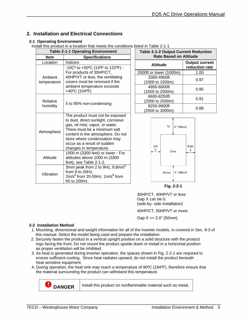
Fig. 2-2-1 30HP/CT, 40HP/VT or less: Gap X can be 0. (side-by- side installation)
40HP/CT, 50HP/VT or more:
Gap X >= 2.0” (50mm)
Altitude 1000 m (3300 feet) or lower - For altitudes above 1000 m (3300 feet), see Table 2-1-2.
Vibration
3mm peak from 2 to 9Hz, 9.8m/s2 from 9 to 20Hz, 2m/s2 from 20-55Hz, 1m/s2 from 55 to 200Hz.
2-2 Installation Method 1. Mounting, dimensional and weight information for all of the inverter models, is covered in Sec. 8-3 of this manual. Select the model being used and prepare the installation. 2. Securely fasten the product in a vertical upright position on a solid structure with the product
logo facing the front. Do not mount the product upside down or install in a horizontal position as proper ventilation will be inhibited. 3. As heat is generated during inverter operation, the spaces shown in Fig. 2-2-1 are required to ensure sufficient cooling. Since heat radiates upward, do not install the product beneath heat sensitive equipment. 4. During operation, the heat sink may reach a temperature of 90ºC (194ºF), therefore ensure that the material surrounding the product can withstand this temperature.
DANGER Install this product on nonflammable material such as metal.
EQ5 AC Drive Operations Manual
______________________________________________________________________ TECO – Westinghouse Motor Company Installation Method 6
5. When installing this product in a control panel,
ensure that the ventilation is sufficient to prevent the ambient temperature of the inverter from exceeding the specified value. Do not install the product in an area where there is inadequate ventilation,
6. If two or more inverters must be installed in the same equipment or control panel, arrange the units horizontally (side by side) to minimize the effect of heat. If two or more inverters must be installed vertically (one on top of the other), place an insulated plate between the inverters to minimize the effect of heat.
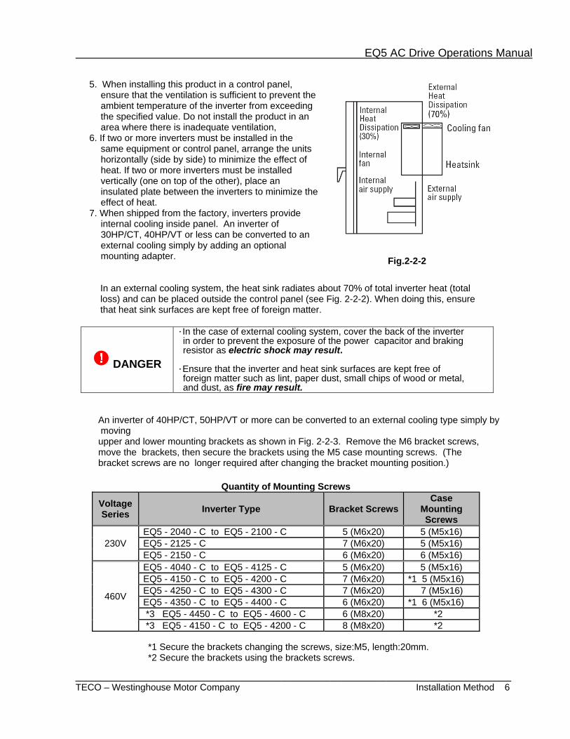
7. When shipped from the factory, inverters provide internal cooling inside panel. An inverter of 30HP/CT, 40HP/VT or less can be converted to an external cooling simply by adding an optional mounting adapter.
In an external cooling system, the heat sink radiates about 70% of total inverter heat (total loss) and can be placed outside the control panel (see Fig. 2-2-2). When doing this, ensure that heat sink surfaces are kept free of foreign matter.
DANGER
・In the case of external cooling system, cover the back of the inverter in order to prevent the exposure of the power capacitor and braking resistor as electric shock may result. ・Ensure that the inverter and heat sink surfaces are kept free of foreign matter such as lint, paper dust, small chips of wood or metal, and dust, as fire may result.
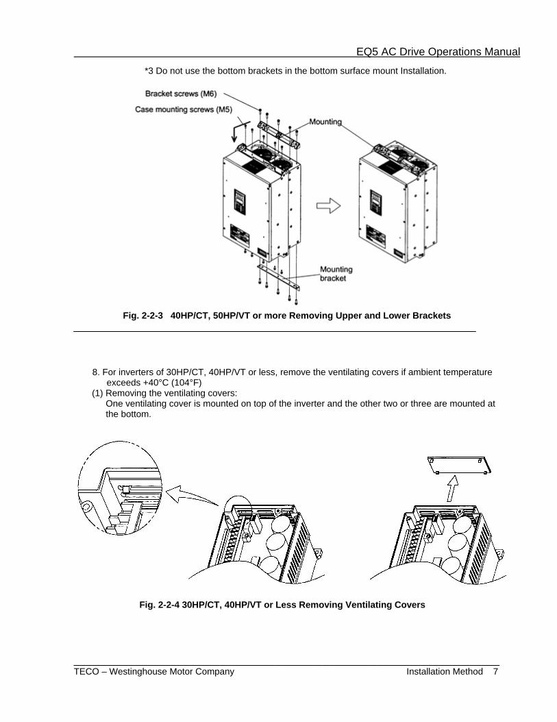
An inverter of 40HP/CT, 50HP/VT or more can be converted to an external cooling type simply by moving
upper and lower mounting brackets as shown in Fig. 2-2-3. Remove the M6 bracket screws, move the brackets, then secure the brackets using the M5 case mounting screws. (The bracket screws are no longer required after changing the bracket mounting position.)
Quantity of Mounting Screws
Voltage Series Inverter Type Bracket Screws
Case Mounting Screws
230V EQ5 - 2040 - C to EQ5 - 2100 - C 5 (M6x20) 5 (M5x16) EQ5 - 2125 - C 7 (M6x20) 5 (M5x16) EQ5 - 2150 - C 6 (M6x20) 6 (M5x16)
460V
EQ5 - 4040 - C to EQ5 - 4125 - C 5 (M6x20) 5 (M5x16) EQ5 - 4150 - C to EQ5 - 4200 - C 7 (M6x20) *1 5 (M5x16) EQ5 - 4250 - C to EQ5 - 4300 - C 7 (M6x20) 7 (M5x16) EQ5 - 4350 - C to EQ5 - 4400 - C 6 (M6x20) *1 6 (M5x16) *3 EQ5 - 4450 - C to EQ5 - 4600 - C 6 (M8x20) *2 *3 EQ5 - 4150 - C to EQ5 - 4200 - C 8 (M8x20) *2
*1 Secure the brackets changing the screws, size:M5, length:20mm. *2 Secure the brackets using the brackets screws.
Fig.2-2-2
EQ5 AC Drive Operations Manual
______________________________________________________________________ TECO – Westinghouse Motor Company Installation Method 7
*3 Do not use the bottom brackets in the bottom surface mount Installation.
Fig. 2-2-3 40HP/CT, 50HP/VT or more Removing Upper and Lower Brackets
8. For inverters of 30HP/CT, 40HP/VT or less, remove the ventilating covers if ambient temperature
exceeds +40°C (104°F) (1) Removing the ventilating covers:
One ventilating cover is mounted on top of the inverter and the other two or three are mounted at the bottom.
Fig. 2-2-4 30HP/CT, 40HP/VT or Less Removing Ventilating Covers
EQ5 AC Drive Operations Manual
______________________________________________________________________ TECO – Westinghouse Motor Company Electrical Connections 8
2-3 Electrical Connections
To access the terminal blocks remove the cover in accordance with the instructions in this manual.
2-3-1 Basic Power Electrical Connections 1. Always connect input power to the main circuit power terminals L1/R, L2/S, and L3/T of the inverter. Check that the input voltage to be applied is within the maximum allowable voltage marked on the nameplate. 2. Always connect the power output terminals U, V, and W to the motor. Check that output voltage rating is correct for the motor being used.
DANGER- Do not connect the input voltage to the motor terminals U, V, and W as extreme damage and / or injury may result. 3. Using the proper wire size and type, always bond the ground terminal to a reliable ground connection to prevent dangerous situations such as the possibility of fire or electrical shock and to minimize electrical noise.
4. Use a secure reliable cable crimp connection between the terminal and a cable. 5. After terminating the wiring connection, ensure the following:
a. The connection is correct. b. All necessary connections have been made. c. There is no short-circuit or ground fault between terminals and cables.
6. If a wiring change needs to be made after power-up, wait at least 5 minutes before making any wiring changes. Also ensure that the charge indicating LED is off. This is necessary because the DC power section capacitor(s) does not discharge immediately after power-down and maintains lethal voltages. The actual DC voltage may also be checked with a multimeter and should be 25VDC or less. If short circuiting the DC voltage after power-down, sparks may occur.
DANGER
• Always properly ground the inverter otherwise electric shock or fire may result.
• Ensure that a licensed specialist performs all wiring and that all codes are met.
• Confirm that the power is turned off and that the charge indicator is off (Wait 5 minutes for 30HP/CT, 40HP/VT and less, 10 minutes for 40HP/CT, 50HP/VT or above) before removing any protective covers as lethal voltages are present and electrical shock may result.
NOTES
EQ5 AC Drive Operations Manual
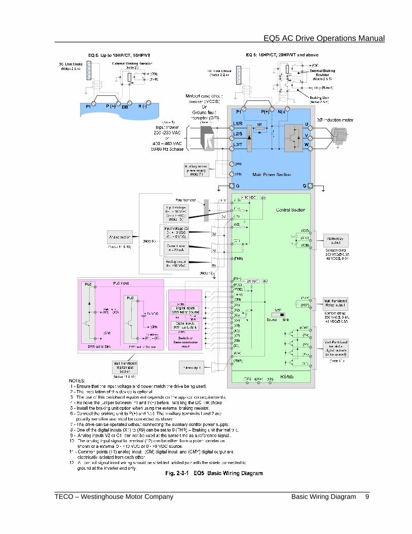
______________________________________________________________________ TECO – Westinghouse Motor Company Basic Wiring Diagram 9
EQ5 AC Drive Operations Manual
______________________________________________________________________ TECO – Westinghouse Motor Company Power Terminal Designations & Wiring 10
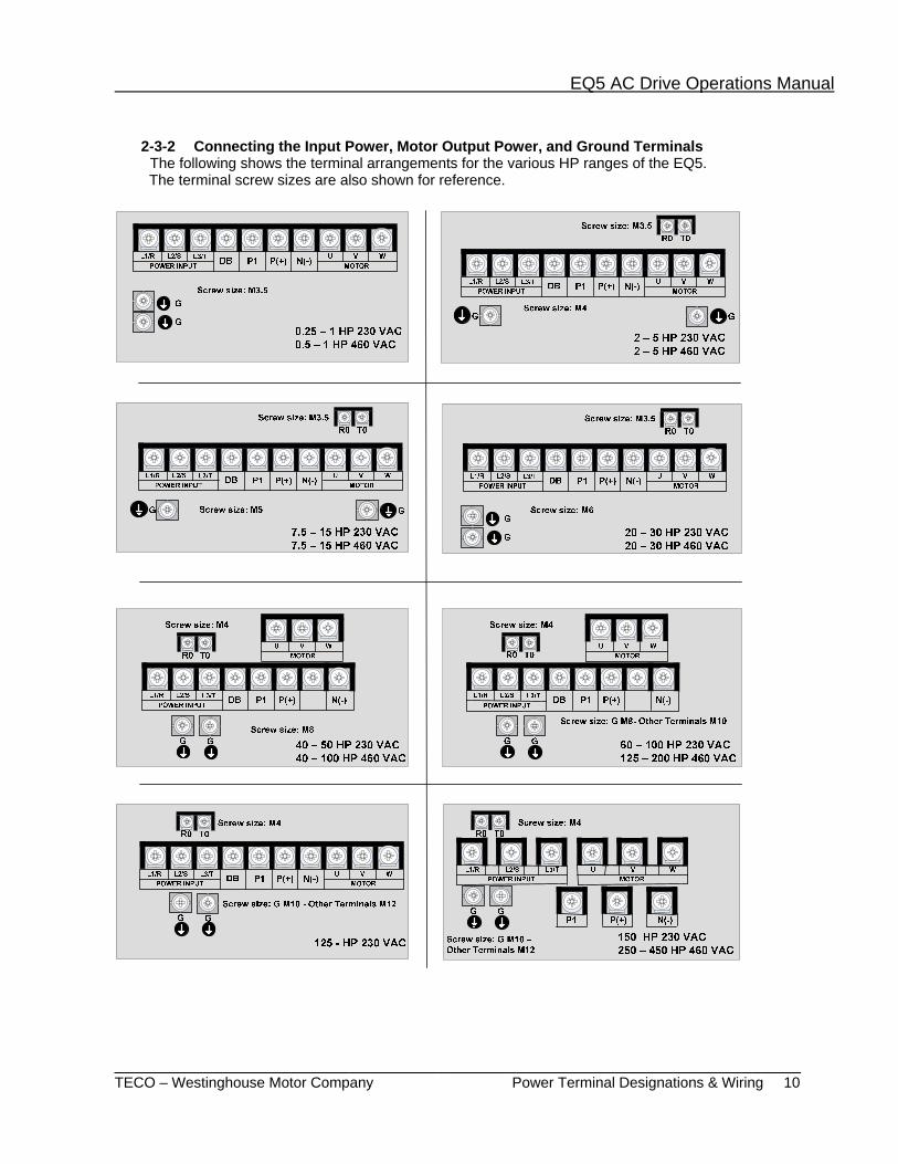
2-3-2 Connecting the Input Power, Motor Output Power, and Ground Terminals The following shows the terminal arrangements for the various HP ranges of the EQ5. The terminal screw sizes are also shown for reference.

EQ5 AC Drive Operations Manual
______________________________________________________________________ TECO – Westinghouse Motor Company Power Terminal Designations & Wiring 11
R0 T0
G G
L1/R L2/S L3/TPOWER INPUT
L1/R L2/S L3/T
U V WMOTOR
U V W
P1
P1
P(+) P(+)
N(-) N(-)
Screw size: M4
Screw size: G M10 –Other Terminals M12
500 – 600 HP 460 VAC
R0 T0
G G
L1/R L2/S L3/TPOWER INPUT
L1/R L2/S L3/T
U V WMOTOR
U V W
P1
P1 P(+)
P(+)
N(-)
N(-)
Screw size: M4
Screw size: G M10 –Other Terminals M12
700 – 800 HP 460 VAC
Table 2-3-1 Functions of Main Circuit Terminals and Ground Terminals Symbol Terminal Name Description
L1/R, L2/S, L3/T Main circuit input power terminals. Connects to a 3-phase power supply.
U, V, W Inverter output terminals Connects to a 3-phase motor.
R0, T0 Auxiliary control-power input terminals.
Connects a backup AC power supply to the control circuit. (Not applicable to inverters of 1HP or less)
P1, P (+) DC link reactor terminal connection.
Connects a power-factor correcting DC link reactor. (optional)
P (+), DB External braking resistor terminal connections.
Connects an external braking resistor for inverters 10HP/CT, 15HP/VT or less.
P (+), N (-) DC link circuit terminals Supplies DC link voltage to the external braking or power regeneration unit (optional).
G Inverter ground terminal Inverter chassis (case) ground. 1. Main circuit input power terminals (L1/R, L2/S, L3/T)
a. For circuit (wiring) protection, connect these terminals to the input power supply using a molded-case circuit breaker or a ground-fault circuit interrupter. Phase-sequence matching is unnecessary. b. To ensure safety, a magnetic contactor should be connected to disconnect the inverter from the input power supply when the inverter protective function activates. c. The main circuit input power should be used to start or stop the inverter only if absolutely necessary and then should not be used more than once every hour. d. If you need to connect these terminals to a single-phase power supply, please consult
the factory.

EQ5 AC Drive Operations Manual
______________________________________________________________________ TECO – Westinghouse Motor Company Power Terminal Designations & Wiring 12
2. Inverter output terminals (U, V, W)
a. Connect these terminals to a 3-phase motor in the correct phase sequence. If the direction of motor rotation is incorrect, swap any two of the U, V, and W phases. b. Do not connect a power factor correction capacitor or surge suppressor to the inverter output. c. If the cable from the inverter to the motor is excessively long, a high-frequency current can be generated by stray capacitance between the cables and result in an overcurrent trip of the inverter, an increase in leakage current, or a reduction in current indication precision. d. When a motor is driven by a PWM-type inverter, the motor terminals may be subject to surge voltage generated by PWM switching. If the motor cables are excessively long, particularly the 460V series units, the surge voltage will deteriorate motor insulation over time. To prevent this, use the following guidelines:
Inverters 7.5HP/CT, 10HP/VT and Higher
Motor Insulation Rating 1000V 1300V 1600V 460 VAC Input Voltage 66 ft (20 m) 328 ft (100 m) 1312 ft (400 m) * 230 VAC Input Voltage 1312 ft (400 m) * 1312 ft (400 m) * 1312 ft (400 m) *
Inverters 5HP/CT/VT and Smaller Motor Insulation Rating 1000V 1300V 1600V 460 VAC Input Voltage 66 ft (20 m) 165 ft (50 m) * 165 ft (50 m) * 230 VAC Input Voltage 328 ft (100 m) * 328 ft (100 m) * 328 ft (100 m) * * In this case the cable length is determined by secondary effects and not voltage spiking.
Note: When a motor protective thermal O/L relay is inserted between the inverter and the motor, the thermal O/L relay may malfunction (particularly in the 460V series units), even when the cable length is 165 feet (50m) or less. To correct this, insert a filter or reduce the PWM carrier frequency. (Use function code “F26 Motor sound”.)
3. Auxiliary control-power input terminals (R0 and T0)
The inverter will operate even if power is not provided to these terminals. If a protective circuit is activated and the magnetic contactor on the inverter power input side is opened (off), the inverter control circuit power, the alarm output (30A, B, and C), and the keypad display will lose power. To prevent this, the same AC power as supplied to the main input circuit must be supplied (as auxiliary control power) to the auxiliary control - power input terminals (R0 and T0). (see Fig. 2-3-2)
a. To ensure effective noise reduction when using an input noise filter, the output from the filter must go to the auxiliary control-power input terminals. If these terminals are
Fig. 2-3-2 Connecting the Auxiliary Control-Power Input Terminals
connected to the input side of the filter, the noise reduction is much less effective.

EQ5 AC Drive Operations Manual
______________________________________________________________________ TECO – Westinghouse Motor Company Power Terminal Designations & Wiring 13
b. When the RCD (Residual-current Protective Device) is installed (30HP/CT, 40HP/VT or less), the terminal R0
and T0 should be connected to the output side of the RCD. If they are connected to the input side, the RCD will malfunction because the power supply of the inverter is three phase and the
R0 and T0 input is single phase. If it is required to connect terminals R0 and T0 are to the input side of the RCD, an isolation transformer is required as shown on the Fig. 2-3-2.
4. Connecting a DC link choke to terminals (P1 and P (+))
a. Before connecting a DC link choke to these terminals, remove the factory-installed jumper. (Fig. 2-3-3) b. If a DC link choke is not used, do not remove the jumper.
Note: For inverters of 100HP or more, the DC link choke is provided as separate standard component and should always be connected. For inverters less than 100 HP, the DC link choke is not provided and is optional.
P(+)P1X
DC Link Choke
Inverter
Fig. 2-3-3 Remove Jumper
4. Connecting an external braking-resistor to terminals (P (+) and DB) (10HP/CT, 15HP/VT or less)
(Fig. 2-3-4). For inverters 10HP/CT, 15HP/VT or less, a built-in braking resistor is connected to terminals P (+) and DB. If this braking resistor does not provide sufficient thermal capacity (e.g. high operating duty cycle or high inertia loads), an optional external braking resistor must be installed to improve braking performance.
a. Remove the internal braking resistor from terminals P(+) and DB and Insulate the terminals with adhesive insulation tape, etc. b. Connect terminals P(+) and DB of the external braking resistor to terminals P(+) and DB of the inverter. c. The wiring (cables twisted or otherwise) should not exceed 16ft (5m).
6. DC link circuit terminals (P (+) and N (-)) (Fig.2-3-5).
The EQ5 inverter of 15HP/CT, 20HP/VT or more does not contain a drive circuit for the braking resistor. To improve braking performance, an optional external braking unit and external braking resistor must be installed.
Fig. 2-3-4 Connection (10HP/CT, 15HP/VT or less)
a. Connect terminals P and N of the braking unit to terminals P(+) and N(-) of the inverter. The wiring (cables twisted or otherwise) should not exceed 16ft(5m).
b. Connect terminals P and DB of the braking resistor to terminals P and DB of the braking unit. The wiring (cables twisted or otherwise) should not exceed 33ft (10m).
c. Connect terminals P and DB of the braking
resistor to terminals P and DB of the braking unit. The wiring (cables twisted or otherwise) should not exceed 33ft (10m).

EQ5 AC Drive Operations Manual
______________________________________________________________________ TECO – Westinghouse Motor Company Power Terminal Designations & Wiring 14
DANGER- When terminals P (+) and N (-) of the inverter are not used, leave terminals open. If P(+) is connected to N (-) the bus voltage will be shorted, or if braking resistor is connected directly, the resistor can cause fire.
d. Auxiliary contacts 1 and 2 of the braking unit are polarity sensitive. To connect the braking unit, refer to the "TECO Inverter
Speecon Braking Unit Manual”.
Fig. 2-3-5 Connection (15HP or more)
7. Inverter ground terminal To ensure safety and noise reduction, always bond the inverter ground terminal. Also, metal frames of electrical equipment must be grounded as specified in applicable codes The connection procedure is as follows:
a. Ground all metal frames and chassis to a ground terminal (Ground resistance: ≤10Ω). b. In accordance with applicable codes, use a suitable ground cable to connect the inverter system to ground.
8. Placement of connector (CN UX) for inverters 40HP/CT, 50HP/VT and higher. When an inverter of 40HP or higher is connected to an input voltage listed in Table 2-3-2, disconnect the auxiliary power connector CN UX from U1 and connect to U2. (Refer to Fig. 2-3-7)
Table 2-3-2 Main Input Voltage Requiring Auxiliary Power Connector Change
Frequency [Hz] Input voltage range [VAC]50 380 - 398 60 380 - 430
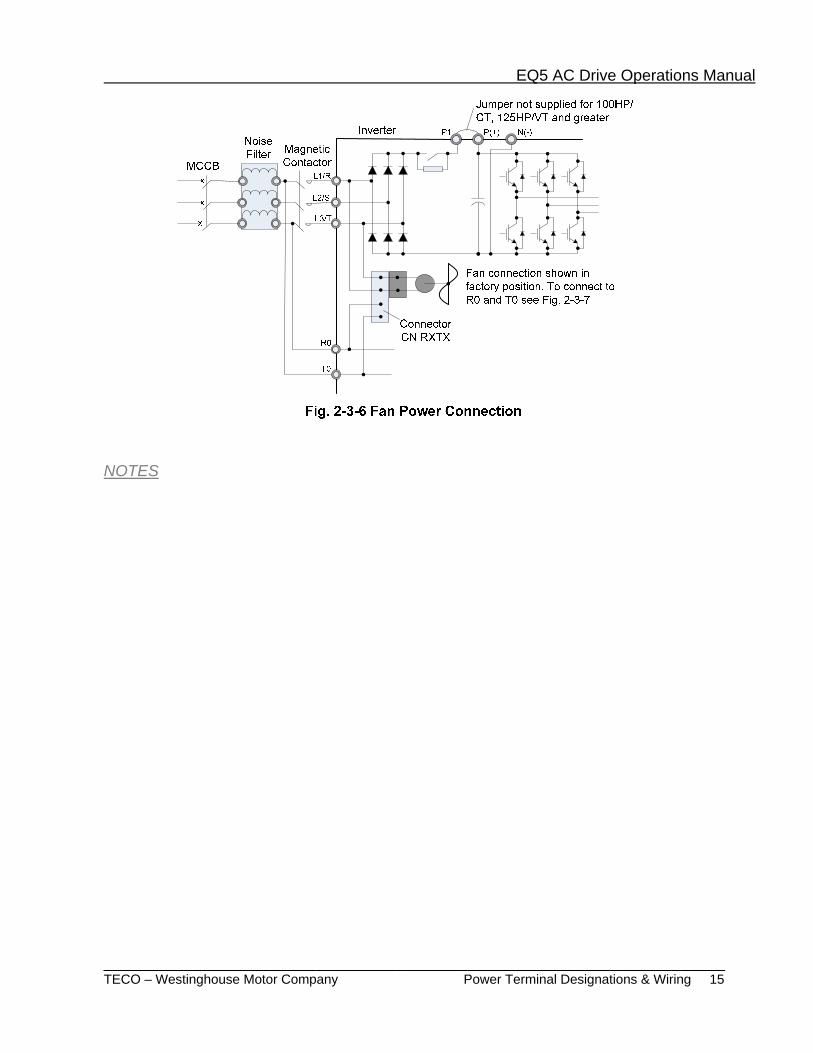
9. Placement of fan power connector (CN RXTX) for inverters 40HP/CT, 50HP/VT or higher. An inverter of 40HP/CT, 50HP/VT or greater uses an AC cooling fan. When the inverter is being operated with DC Input power, the fan must still be energized from an AC power source. To do this, position the fan connector (CN RTXT) as shown in Fig. 2-3-9 and provide AC voltage to auxiliary input terminals R0 and T0. For the (CN RTXT) connector placement method, see Fig. 2-3-7.
Note: When shipped, the fan connector (CN RXTX) is connected to L1/R-L3/T. Do not change the connector position unless DC power is being used.
EQ5 AC Drive Operations Manual
______________________________________________________________________ TECO – Westinghouse Motor Company Power Terminal Designations & Wiring 15
NOTES

EQ5 AC Drive Operations Manual
______________________________________________________________________ TECO – Westinghouse Motor Company Power Terminal Designations & Wiring 16
The connectors are mounted on the power PCB above the control PCB as shown on the right.
EQ5-4040-C to EQ5-4200-C EQ5-2040-C to EQ5-14150-C
Note: To remove a connector, squeeze the locking mechanism and pull. To mount a connector, push the connector down until it locks (clicks).
EQ5-4250-C to EQ5-4900-C When shipped from the factory, CN UX is connected to U1 and CN RXTX is connected to L1/R-L3/T.
Fig. 2-3-7 (CN UX) and (CN RXTX) Connector Locations and Orientation
<Enlarged view of part A>

EQ5 AC Drive Operations Manual
_____________________________________________________________________ TECO – Westinghouse Motor Company Control Terminal Designations & Wiring 17
2-3-3 Connecting the Control Terminals Table 2-3-3 lists the functions of the control circuit terminals. The connections to the control terminals will be in accordance with its function setting.
Table 2-3-3 Control Terminal Functions
Classification Terminal Symbol Terminal Name Function
Analog input
13 Potentiometer power supply
Supplies +10V DC to an externally connected frequency control potentiometer (1 to 5kΩ).
12 Voltage input 1
1- Sets the output frequency in accordance with an analog input voltage applied from an external circuit.
- 0 to +10V DC / 0 to 100% - Reversible operation using positive and negative signals: 0 to +/-10V DC / 0 to +/-100%
- Reverse operation: +10 to 0V DC / 0 to 100% 2- Feedback signal for PID control. 3- Output torque control. * Terminal Input resistance: 22kΩ
V2 Voltage input 2
Sets the output frequency in accordance with an analog input voltage applied from an external circuit.
- 0 to +10V DC / 0 to 100% - Reverse operation:+10 to 0V DC / 0 to 100%
* Terminals "V2" and "C1" cannot be used at the same time. * Terminal Input resistance: 22kΩ
C1 Current input
1- Sets the output frequency in accordance with an analog input current applied from an external circuit. - 4 to 20mA DC / 0 to 100% - Reverse operation: 20 to 4mA DC / 0 to 100%
2- Feedback signal for PID control. 3- PTC thermistor input.
13
C1
V2
11
11kΩ
11kΩ
1kΩ
ON OFF
PTC
+
_
250Ω
* Terminals "V2" and "C1" cannot be used at the same time. * Terminal Input resistance: 250Ω * PTC switch is off when function not used.
11 Analog input common Common terminal for analog input and output signals

EQ5 AC Drive Operations Manual
______________________________________________________________________ TECO – Westinghouse Motor Company Control Terminal Designations & Wiring 18
Digital input
FWD Forward operation / stop command
Forward operation (when FWD-CM is on) or deceleration and stop (when FWD-CM is open).
REV Reverse operation / stop command
Reverse operation (when REV-CM is on) or deceleration and stop (when REV-CM is open).
X1 Digital input 1 The coast-to-stop command, external alarm, alarm reset, multi-step frequency selection, and other functions (from an external circuit) can be assigned to terminals X1 to X9. For details, see "Setting the Terminal Functions E01 to E09" in Section 5.3 Function Explanation. <Specifications of digital input circuit> *
Item min. typ. max. Operating voltage ON 2V - 2V
OFF 22V 24V 27V Operating current level ON - 3.2mA 4.5mA
Leakage current OFF - - 0.5mA
FWD, REVX1 – X9
CM
PLC
6.8kΩ
+24V
0V
X2 Digital input 2 X3 Digital input 3 X4 Digital input 4 X5 Digital input 5 X6 Digital input 6 X7 Digital input 7 X8 Digital input 8 X9 Digital input 9
CM Common terminal Common terminal for digital inputs ,FMP and P24.
P24 Control Unit power Supply
+24VDC power supply for control input. Maximum output current 100mA
PLC PLC signal power Used to connect to a PLC power supply output 22 to 27 VDC, input signals set to sink logic operation.
Analog output FMA (11 Com) Analog monitor
Analog output DC voltage 0 to +10V DC. The signal is selected to indicate one of the following: -Output frequency (before slip compensation) -Power consumption -Output frequency (after slip compensation) -PID feedback value -Output current -PG feedback value -Output voltage -DC link circuit voltage -Output torque -Load factor *Minimum load resistance: 5kΩ

EQ5 AC Drive Operations Manual
______________________________________________________________________ TECO – Westinghouse Motor Company Control Terminal Designations & Wiring 19
Pulse output FMP
(CM Com) Frequency monitor (pulse output)
Outputs a pulse frequency indicating the same as that of the analog FMA signal.
Transistor output
Y1 Transistor output1 A running signal, frequency equivalence signal, overload early warning signal, and other signals from the inverter are output (as a transistor output) to terminals Y1-Y4. For details, see "Setting the Terminal Functions E20 to E23" in Section 5.3 Function Explanation
Transistor output circuit specifications Item min. typ. max.
Operating voltage
ON - 2V 3V OFF - 24V 27V
Maximum load current ON - - 50mA Leakage current OFF - - 0.1mA
Y2 Transistor output2 Y3 Transistor output3 Y4 Transistor output4
CME Transistor output common
Common terminal for transistor output signals This terminal is insolated from terminals [CM] and [11].
Relay outputs
30A,30B, 30C
Alarm output for any fault
If the inverter is stopped by an alarm (protective function), the relay (SPDT) will activate. Contact rating: 250 VAC, .03A - 48V DC, 0.5A The activation mode can be selected for normal or alarm operation.
Y5A,Y5C Multipurpose-signal relay output
The activation signals can be the same as the Y1 -Y4 outputs above. The contact ratings are the same as that of the alarm output above.
Communication
DX+, DX- RS485 Modbus RTU communication
Terminals for RS485 communication (Modbus RTU). UP to 31 inverters can be connected using the daisy chain method.
SD Communication-cable shield connection terminal
Terminal for connecting the shield of the communication cable. The terminal is electrically floating.
(1) Analog input terminals (13,12,V2,C1,and 11) a. These terminals receive analog signals that may be affected by external noise. The cables should be as short
as possible (66ft /20m or less), be shielded twisted cable, and must be properly grounded. If the cables are affected by externally induced noise, the shielding effect may be improved by connecting the shield to terminal [11]. (see Fig. 2-3-8)
b. If contacts are used to connect to these circuits, twin (bifurcated type) contacts for handling low level
signals must be used. A contact must not be connected to terminal [11].
c. If an external analog signal output device is connected to these terminals, it may malfunction as a result of inverter noise. To prevent malfunction, connect a ferrite core or capacitor to the external analog signal output device as shown in Fig. 2-3-9.

EQ5 AC Drive Operations Manual
______________________________________________________________________ TECO – Westinghouse Motor Company Control Terminal Designations & Wiring 20
(2) Digital input terminals (FWD, REV, X1 to X9, and CM)
a. Digital input terminals FWD, REV and X1 to X9 are generally turned on or off by switching the input to (P24) +24V (source logic) or to (CM) 0V (sink logic). If the digital input terminals are turned on or off by a PLC with open collector using an external power supply, a resulting bypass circuit may cause the inverter to malfunction. To prevent this, connect the PLC terminal as shown in Fig. 2-3-10. b. When using a dry contact input such as a relay, highly reliable contacts capable of handling low level signals must be used.
(3) Transistor output terminals (Y1 to Y4, CME) a. Refer to the circuit configuration in Table 2-3-3 Transistor Output and confirm the polarity of the
external power supply. b. When connecting a control relay to the transistor output, connect a transient absorbing diode to both ends of the relays’ exciting coil.
(4) Sink or Source Logic selection a. The slide switch SW1 located on the control board, sets the digital inputs for sink or source
input logic. The factory default is the sink position and is most commonly used in the US while source logic is common in Europe.
b. For proper input digital connections, refer to the EQ 5 wiring diagram as well as other sections covering this subject. Ensure that the correct position is selected for a particular application.
(5) Others a. To prevent faulty operation as a result of noise, the control terminal cables should be placed as far as possible from the main power cables.
b. The control cables inside the inverter must be secured to prevent direct contact with the main power section, such as the power terminal block.
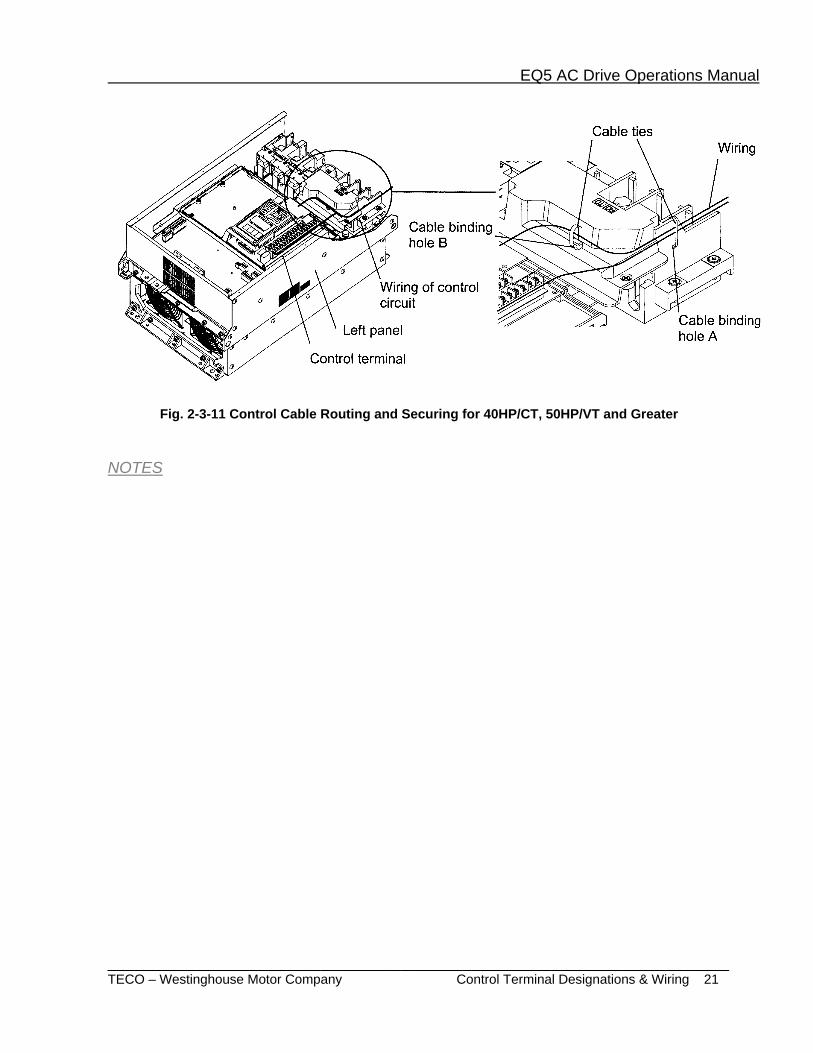
(6) Wiring of the control circuit (40HP/CT, 50HP/VT or greater) a. Pull out the control circuit wiring along the left panel as shown in Fig. 2-3-11. b. Secure the cable binding hole A on the left wall of the power terminal block using a cable tie. Note: The cable tie should not exceed 0.14 ”(3.5mm) in width and 0.06” (1.5mm) in thickness. c. When an optional PC card is mounted, the signal cables must be secured to cable binding hole B.
EQ5 AC Drive Operations Manual
______________________________________________________________________ TECO – Westinghouse Motor Company Control Terminal Designations & Wiring 21
Fig. 2-3-11 Control Cable Routing and Securing for 40HP/CT, 50HP/VT and Greater NOTES

EQ5 AC Drive Operations Manual
______________________________________________________________________ TECO – Westinghouse Motor Company Input Protection Device Ratings 22
2-3-4 Input Protective Device Ratings.
Input Voltage
HP Rating (VT / CT)
Input Fuse (AMPS) Input Circuit Breaker (AMPS) (Note 1)
L1/R, L2/S & L3/T
(Nominal)
L1/R, L2/S & L3/T
(Maximum) (Note 1)
Auxiliary Input
R0 & T0
230 VAC
0.25 / 0.25 3 3 3 15 0.5 / 0.5 5 6 3 15
1 / 1 10 15 3 20 2 / 2 15 20 3 30 3 / 3 20 30 3 40 5 / 5 35 50 3 60
7.5 / 5 60 80 3 100 10 / 7.5 70 125 3 125 15 / 10 100 150 3 175 20 / 15 125 200 3 225 25 / 20 150 225 3 250 30 / 25 175 250 3 300 30 / 30 175 250 3 300 40 / 30 200 * 5 200 50 / 40 225 * 5 225 60 / 50 300 * 5 300 75 / 60 350 * 5 350
100 / 75 300 * 5 300 125 / 100 400 * 5 400 150 / 125 450 * 5 450
460VAC
0.5 / 0.5 3 3 3 151 / 1 5 6 3 152 / 2 10 10 3 153 / 3 15 15 3 20 5 / 5 20 25 3 35
7.5 / 5 30 45 3 50 10 / 7.5 40 60 3 70 15 / 10 50 90 3 90 20 / 15 70 110 3 110 25 / 20 80 125 3 150 30 / 25 100 125 3 175 30 / 30 100 125 3 175 40 / 30 100 * 10 100 50 / 40 125 * 10 125 60 / 50 175 * 10 175 75 / 60 150 * 10 150
100 / 75 175 * 10 175 125 / 100 200 * 10 200 150 / 125 225 * 10 225 200 /150 300 * 10 300 250 / 200 450 * 10 400 300 / 250 500 * 10 450 350 / 300 500 * 10 500 400 / 350 600 * 10 600 450 / 350 700 * 10 700 500 / 400 700 * 10 700 600 / 450 1000 * 10 1000 700 / 500 1000 * 10 1000 800 / 600 1200 * 10 1200
Note 1 - Class J fuse or circuit breaker rated 600V with the maximum current rating as shown in the above table to be connected to a drive 30HP/CT, 40HP/VT and less.

EQ5 AC Drive Operations Manual
______________________________________________________________________ TECO – Westinghouse Motor Company Terminal Tightening Torques & Wire Size 23
2-3-5 EQ5 Terminal Tightening Torque and Cable Size
Inpu
t Vol
tage
HP Rating
(CT / VT)
Terminal Tightening Torque Ib – in (Nm) (Note 4) Cable Size AWG (Note 3)
L1/R, L2/S,
L3/T, U, V, W, P1 & P(+)
E (G)
DB Circuit
P(+), N(-) & DB
(Note 1)
R0 & T0
L1/R, L2/S & L3/T
U, V & W DC
Reactor, P1 & P(+)
DB Cir. P(+), N(-)
& DB (Note 1)
R0 &
T0
230 VAC
0.25 / 0.25 10.6 (1.2) 10.6 (1.2) - 16 16 - 0.5 / 0.5
1 / 1 2 / 2
20.8 (2.36) 20.8 (2.36)
10.6 (1.2)
14
3 / 3 14
14
5 / 5 10 5 / 7.5 31.0 (3.5)
31.0 (3.5)
8 7.5 / 10 6 10 / 15
51.3 ( 5.8)
4 15 / 20 3 20 / 25 2 25 / 30 30 / 30 1
30 / 40 119 (13.5) 4/0 1/0 2/0
10
40 / 50 10 50 / 60
239 (27) 119 (13.5) 119 (13.5)
Qty 2-1 3/0 4/0 60 / 75 Qty 2-2/0 4/0 Qty 2-1
75 / 100 Qty 2-3/0 Qty 2-1/0 Qty 2-2/0 8 100 / 120 425 (48) 239 (27) Qty 2-2/0 Qty 2-3/0 Qty 2-4/0 6 125 / 150 Qty 2-4/0 Qty 2-4/0 Qty 2-250 4
460 VAC
0.5 / 0.5 10.6 (1.2) 10.6 (1.2) - 16 16
- 1 / 1 2 / 2
20.8 (2.36) 20.8 (2.36)
10.6 (1.2)
14 3 / 3 5 / 5 14
14
-
5 / 7.5 31.0 (3.5)
31.0 (3.5)
12 7.5 / 10 10 10 / 15
51.3 ( 5.8) 15 / 20 8 20 / 25 6 25 / 30 30 / 30 4
30 / 40
119 (13.5)
2 3 3
10
40 / 50 1 2 2 50 / 60
51.3 ( 5.8)
2/0 2 1 60 / 75 3/0 2/0 2/0
75 / 100
239 (27)
119 (13.5) 2/0 4/0 4/0
100 / 125
239 (27)
3/0 4/0 Qty 2-1 10 125 / 150 119 (13.5) Qty 2-1/0 Qty 2-1/0 Qty 2-1/0 8 150 / 200 Qty 2-1/0 Qty 2-2/0 Qty 2-3/0 200 / 250
425 (48)
239 (27) Qty 2-3/0 Qty 2-3/0 Qty 2-4/0 6
250 / 300 Qty 2-4/0 Qt y2-250 Qty 2-300 4 300 / 350 Qty 2-250 Qty 2-300 Qty 2-350 350 / 400
(Note 2)
Qty 2-350 Qty 2-400 Qt y2-500
(Note 2)
350 / 450 Qty 2-500 Qty 2-500 Qt y2-700 400 / 500 Qty 2-350 Qty 2-400 Qty 2-500 450 / 600 Qty 2-500 Qty 2-500 Qty 2-700 500 / 700 Qty 2-600 Qty 2-600 Qty 2-800 600 / 800 Qty 2-700 Qty 2-750 Qty 2-1000
Notes 1 - Based on TWMC standard DB unit and DB resistor designs. 2 - Consult Factory. 3 - Wire size from NEC tables 310-16. Copper wire rated 60°C for 100 Amps or less, 75°C for over 100 Amps in 30°C Ambient, and 1.25 x drive rated Amps. 4 - Control terminals tightening torque, 6.2 (0.7)

EQ5 AC Drive Operations Manual
______________________________________________________________________ TECO – Westinghouse Motor Company DC Link Chokes 24
2-3-6 DC Link Choke Wattage Loss
Fig. 2-3-12 DC Link Choke Note: Please refer to Sec. 8- 3- 4 for dimensions and weights.
Input Voltage Hp Model No. Loss
(Watts)
230V 100/75 DCR2-75B 55 125/100 DCR2-90B 57 150/125 DCR2-110B 67
460V
100/75 DCR4-75B 58 125/100 DCR4-90B 64 150/125 DCR4-110B 73 200/150 DCR4-132B 84 250/200 DCR4-160B 90 300/250 DCR4-200B 126 350/300 DCR4-220B 131 400/350 DCR4-280B 133 450/350 DCR4-280B 150 500/400 DCR4-355B 205 600/450 DCR4-400B 215 700/500 DCR4-450B 272 800/600 DCR4-500B 292
Notes: • EQ5 Drives rated 100 Hp and above are furnished with a DC link choke. This choke must be installed between terminals P1 and P+ prior to applying power to the Drive. • The weight of the DC Link Reactor is not included as part of weight referenced for the Drive. • The DC Link choke is provided as open type and is separately mounted. Any enclosures are to be provided by the user.
EQ5 AC Drive Operations Manual
______________________________________________________________________ TECO – Westinghouse Motor Company Initial Operation 25
3. Initial Operation
3-1 Inspection and Preparation Before Operation Check the following before operation:
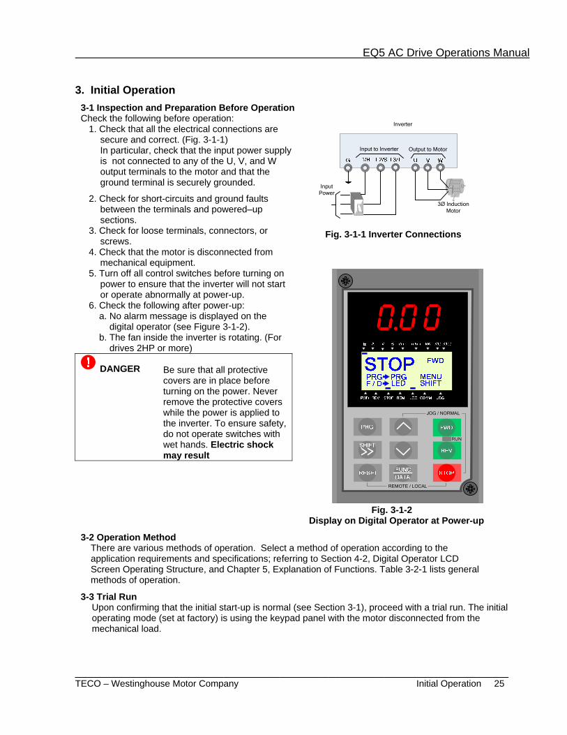
1. Check that all the electrical connections are secure and correct. (Fig. 3-1-1) In particular, check that the input power supply is not connected to any of the U, V, and W output terminals to the motor and that the ground terminal is securely grounded.
2. Check for short-circuits and ground faults between the terminals and powered–up sections.
3. Check for loose terminals, connectors, or screws.
4. Check that the motor is disconnected from mechanical equipment.
Input
Power
3Ø Induction Motor
Inverter
Output to MotorInput to Inverter
Fig. 3-1-1 Inverter Connections
5. Turn off all control switches before turning on power to ensure that the inverter will not start or operate abnormally at power-up.
6. Check the following after power-up: a. No alarm message is displayed on the digital operator (see Figure 3-1-2). b. The fan inside the inverter is rotating. (For drives 2HP or more)
RUN
JOG / NORMAL
REMOTE / LOCAL
Fig. 3-1-2 Display on Digital Operator at Power-up
DANGER Be sure that all protective covers are in place before turning on the power. Never remove the protective covers while the power is applied to the inverter. To ensure safety, do not operate switches with wet hands. Electric shock may result
3-2 Operation Method There are various methods of operation. Select a method of operation according to the application requirements and specifications; referring to Section 4-2, Digital Operator LCD Screen Operating Structure, and Chapter 5, Explanation of Functions. Table 3-2-1 lists general methods of operation.
3-3 Trial Run Upon confirming that the initial start-up is normal (see Section 3-1), proceed with a trial run. The initial operating mode (set at factory) is using the keypad panel with the motor disconnected from the mechanical load.
EQ5 AC Drive Operations Manual
______________________________________________________________________ TECO – Westinghouse Motor Company Initial Operation 26
4. Power down the inverter and following safety precautions, connect the motor. Power-up the drive and repeat steps 1-3 and check the following. a. Is the direction of rotation correct?
b. Is the motor rotating smoothly with no buzzing or abnormal vibration ?
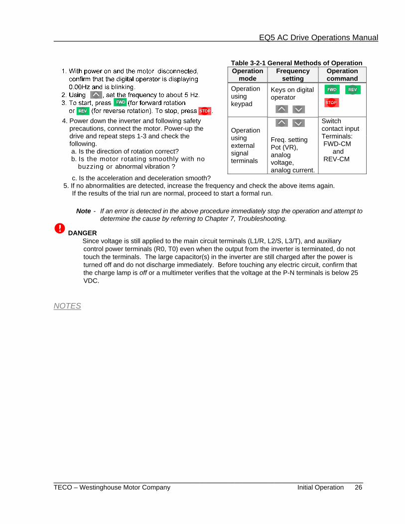
Table 3-2-1 General Methods of Operation Operation
mode Frequency
setting Operation command
Operation using keypad
Keys on digital operator
Operation using external signal terminals
Switch contact input Terminals: FWD-CM and REV-CM
Freq. setting Pot (VR), analog voltage, analog current.
c. Is the acceleration and deceleration smooth? 5. If no abnormalities are detected, increase the frequency and check the above items again. If the results of the trial run are normal, proceed to start a formal run.
Note - If an error is detected in the above procedure immediately stop the operation and attempt to determine the cause by referring to Chapter 7, Troubleshooting.
DANGER Since voltage is still applied to the main circuit terminals (L1/R, L2/S, L3/T), and auxiliary
control power terminals (R0, T0) even when the output from the inverter is terminated, do not touch the terminals. The large capacitor(s) in the inverter are still charged after the power is turned off and do not discharge immediately. Before touching any electric circuit, confirm that the charge lamp is off or a multimeter verifies that the voltage at the P-N terminals is below 25 VDC.
NOTES

EQ5 AC Drive Operations Manual
______________________________________________________________________ TECO – Westinghouse Motor Company Digital Operator Appearance & Key Functions 27
4. Digital Operator The Digital Operator has various functions for inputting, controlling, and displaying operations such as frequency setting, run/stop command, confirming and changing function data, confirming status, and copying. Please review and become familiar with each function before attempting to operate the drive. The Digital Operator can be removed or inserted during inverter operation, however, if it is removed during a keypad operation (e.g., run/stop, frequency setting), the inverter will stop and initiate an alarm.
4-1 Appearance of Digital Operator
LED Monitor: 4-digit 7-segment display used to display data such as setting frequency, output frequency and alarm code. Auxiliary Information Indication for LED Monitor: Indicates selected units or multiple of the monitored data shown on the LED monitor and is displayed on the top line of the LCD monitor. The
symbol indicates selected units or multiple number. The symbol indicates there is an upper screen not currently displayed. LCD Monitor: Used to display various items of information as operation status and function data. An operation guide message, which can be scrolled, is displayed at the bottom of the LCD monitor. This LCD monitor has a backlight feature which turns on when the control power is applied or any keypad key is pressed. It stays on approximately 5 minutes after the last key stroke. Indication on LCD Monitor: Displays one of the following operation status:
FWD: Forward operation REV: Reverse operation STOP: Stop
Control Keys (valid during digital operator operation): Used for inverter run and stop
Operation Keys: Used for switching screens, data change, frequency setting, etc. (Table 4-4-1)
Displays the selected operation mode: REM: Terminal block LOC: Keypad panel COMM: Communication terminal JOG: Jogging mode
The symbol indicates there is a lower screen not currently displayed.
Run LED :

EQ5 AC Drive Operations Manual
______________________________________________________________________ TECO – Westinghouse Motor Company Key Functions, LCD Screen Structure & Alarm Modes 28
Table 4-1-1 Functions of Operation Keys Operation Key Main Function
Used to switch the current screen display to the menu screen or switch to the initial display screen in the operation/trip mode.
Used to switch the LED monitor or to determine the entered frequency, function code, or data.
Used to change data, move the cursor up or down, or scroll the display screen.
Used to move the cursor horizontally when changing data. When this key is pressed with the up or down key, the cursor moves to the next parameter function block.
Used to cancel the current input data and switch the display screen. If an alarm occurs, this key is used to reset the trip status (valid only when the alarm mode initial screen is displayed).
STOP
Used to switch normal operation mode to jogging operation mode or vice versa. The selected mode is displayed on the LCD screen.
STOP + RESET
Switches the operating mode from digital operator to terminal block operation (Local / Remote), and vice versa. When these keys are operated, function F01 data is automatically set to 3 if set at 0, or automatically set to 0 if set from 1 thru 4. The selected mode is displayed on the LCD screen.
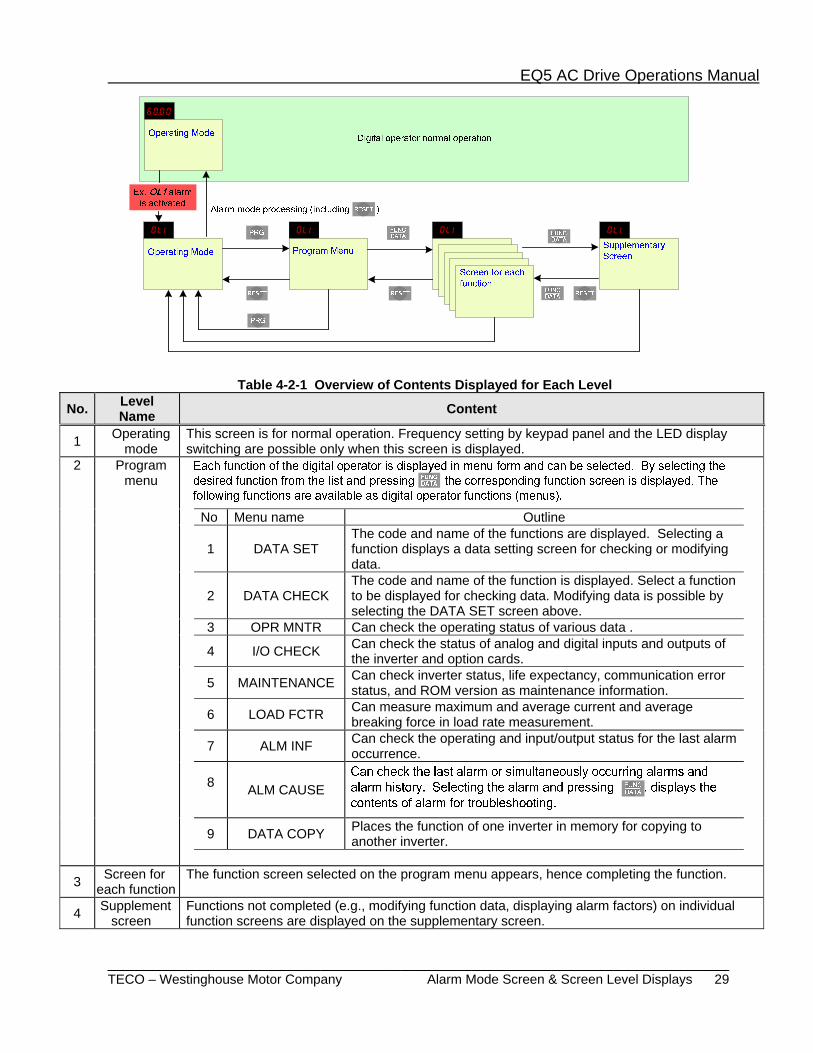
4-2 Digital Operator LCD Screen Operating Structure 4.2.1 Normal Operation The Digital operator LCD operating structure.
PRG
Program MenuOperating Mode
Screen for each function
SupplementaryScreen
RESET
FUNCDATA
RESET RESET
FUNCDATA
FUNCDATA
PRG
4.2.2 Alarm modes
If an alarm is activated, operation is changed from normal digital operator function to alarm mode operation. The alarm mode screen appears and alarm information is displayed.
The program menu, function screens, and supplementary screens remain unchanged as during normal operation, though the switching method from program menu to alarm mode is limited to
.
EQ5 AC Drive Operations Manual
______________________________________________________________________ TECO – Westinghouse Motor Company Alarm Mode Screen & Screen Level Displays 29
Table 4-2-1 Overview of Contents Displayed for Each Level
No. Level Name Content
1 Operating mode
This screen is for normal operation. Frequency setting by keypad panel and the LED display switching are possible only when this screen is displayed.
2 Program menu
No Menu name Outline
1 DATA SET The code and name of the functions are displayed. Selecting a function displays a data setting screen for checking or modifying data.
2 DATA CHECK The code and name of the function is displayed. Select a function to be displayed for checking data. Modifying data is possible by selecting the DATA SET screen above.
3 OPR MNTR Can check the operating status of various data .
4 I/O CHECK Can check the status of analog and digital inputs and outputs of the inverter and option cards.
5 MAINTENANCE Can check inverter status, life expectancy, communication error status, and ROM version as maintenance information.
6 LOAD FCTR Can measure maximum and average current and average breaking force in load rate measurement.
7 ALM INF Can check the operating and input/output status for the last alarm occurrence.
8 ALM CAUSE
9 DATA COPY Places the function of one inverter in memory for copying to another inverter.
3 Screen for each function
The function screen selected on the program menu appears, hence completing the function.
4 Supplement screen
Functions not completed (e.g., modifying function data, displaying alarm factors) on individual function screens are displayed on the supplementary screen.

EQ5 AC Drive Operations Manual
______________________________________________________________________ TECO – Westinghouse Motor Company LED Monitor Display & Program Menu Screen 30
4-3 Digital Operator Keypad Navigation 4-3-1 Operation Mode The LCD screen for normal inverter operation displays the inverter operating status and an operation guide. A second screen is available which graphically displays the operating status in the form of a bar graph. Switching between screens is possible by setting the value of parameter E45 (=1 operation guide), (=2 bar graph).
1) Operation status (E45=0)
RUN FWD
PRG PRG MENUF / D LED SHIFT
STOP FWD
PRG PRG MENUF / D LED SHIFT
2) Bar graph (E45=1)
Output frequency (maximum frequency at full scale)
Output current (200% of inverter rating at full-scale)Torque calculation (200% of inverter rating at full-scale)Fout/Iout/TRQ
Hz
A%
1) Output frequency control set by Digital operator (F01=0 or C30=0)
RUN FWD
PRG PRG MENUF / D LED SHIFT
LOCAL0.00 ~ 60.00F / D STORE
< DIG. SET Hz > LOCAL0.00 ~ 60.00F / D STORE
< DIG. SET Hz >
2) Output frequency set by external source (F01≠0)
RUN FWD
PRG PRG MENUF / D LED SHIFT
12+V1< REMOTE REF >
EQ5 AC Drive Operations Manual
______________________________________________________________________ TECO – Westinghouse Motor Company LED Monitor Display & Program Menu Screen 31
When stopped While running
(E44 =0,1) Units Remarks (E44 = 0) (E44 = 1)
0 Setting frequency
Output frequency 1 (before slip compensation)
Hz
1 Setting frequency Output frequency 2 (after slip compensation)
2 Setting frequency Setting frequency
3 Output current Output current A
4 Output voltage (specified value) Output voltage (specified value) V
5 Synchronous speed setting value
Synchronous speed r/min. For 4 digits or more, the last digits are cut, with x10, x100 marked on the indicator.
6 Line speed setting value Line speed m/min.
7 Load rotation speed setting value
Load rotation speed r/min.
8 Torque calculation value Torque calculation value % ± indication
9 Power consumption Power consumption kW
10 PID setting value PID setting value − Displayed only when the PID function is selected.
11 PID remote setting value PID remote setting value −
12 PID feedback value PID feedback value −
E43
EQ5 AC Drive Operations Manual
______________________________________________________________________ TECO – Westinghouse Motor Company Setting Parameter Values 32
4-3-5 Setting the Parameter (function code) Value On the program menu screen, select 1. DATA SET as in para. 4-3-3. The parameter select screen appears. Select the desired parameter and set value as follows.
RUN FWD
PRG PRG MENUF / D LED SHIFT
The parameter designations (function codes) consist of alphanumeric characters with unique alphabetical letters assigned to each parameter group as in table 4-3-1 below.
Table 4-3-1 Parameter Designations and Corresponding Groups Parameter Group name Remarks F00 - F42 Fundamental Functions E01 - E47 Extension Terminal Functions C01 - C33 Control Functions of Frequency P01 - P09 Motor Parameters H03 - H39 High Performance Functions A01 - A18 Alternative Motor Parameters U01 - U61 User Functions
o01 - o55 Optional Functions Can be selected only with an option connected.

EQ5 AC Drive Operations Manual
______________________________________________________________________ TECO – Westinghouse Motor Company Checking Parameter Values & Operating Status 33
Table 4-3-2 Display Reason for No Modification To Enable Data Change
LINK ACTIVE Currently writing from RS-485/RTUoption to function is being made.
Send a cancel command to function writing from RS-485/RTU. Stops a “write” operation from the link.
NO SIGNAL(WE) The edit enabling command function is selected using a general-purpose input terminal.
For functions E01 to E09, turn data terminal 19 (edit enabling command selection) ON.
DATA PRTCTD Data protection is selected by parameter F00.
Change F00 to 0.
INV RUNNING An attempt is made to change a function that cannot be changed during inverter operation.
Stop inverter operation.
FWD/REV ON An attempt is made to change a function that cannot be changed with the FWD / REV command on.
Turn FWD / REV command off.
4.3.6 Checking Parameter Values Select 2. DATA CHECK on the program menu screen. The parameter select screen then appears with the parameters and current values. (Note that an * will appear before the current value if it was changed from the original value.)
RUN FWD
PRG PRG MENUF / D LED SHIFT
4.3.7 Monitoring Operating Status Select 3. OPR MNTR on the program menu screen to display the current inverter operating status.
RUN FWD
PRG PRG MENUF / D LED SHIFT

EQ5 AC Drive Operations Manual
_______________________________________________________________________ TECO – Westinghouse Motor Company Checking I / O Status 34
RUN FWD
PRG PRG MENUF / D LED SHIFT
FUNCDATA
REM FWD REVX1
PRG1.DATA SET2.DATA CHECK3.OPR MNTR4.I/O CHECK
X2X3 X4X5
X6X7 X8X9
COMM FWD REVX1
X2X3 X4X5
X6X7 X8X9
Y1Y2 Y3Y4
Y5
12 = + XX.XV 22 = + XX.XV 32 = + XX.XV V2 = + XX.XV
Terminal 12 Input Terminal 22 Input (AIO Option) Terminal 32 Input (AIO Option)Terminal V2 Input
C1 = XX.XmA C2 = XX.XmA
Terminal C1 Input Terminal C2 Input (AIO Option)
FMA = XX.XV FMP = XX.XV FMP = XXXX0p/s
FMA Output VoltageFMP Output VoltageFMP Output Frequency
AO = XX.XV CS = XX.XmA DI = XXXXH DO = XXH
Analog Output (V) (AIO Option)Analog Output (I) (AIO Option) Digital Input Terminal (HEX) Digital Output Terminal (HEX)
Analog OutputDIO Option I/O Status
Analog Input Voltage Value Analog Input Current Value
Output Terminal Status Input Status via Communication
Input Status via Terminals
EQ5 AC Drive Operations Manual
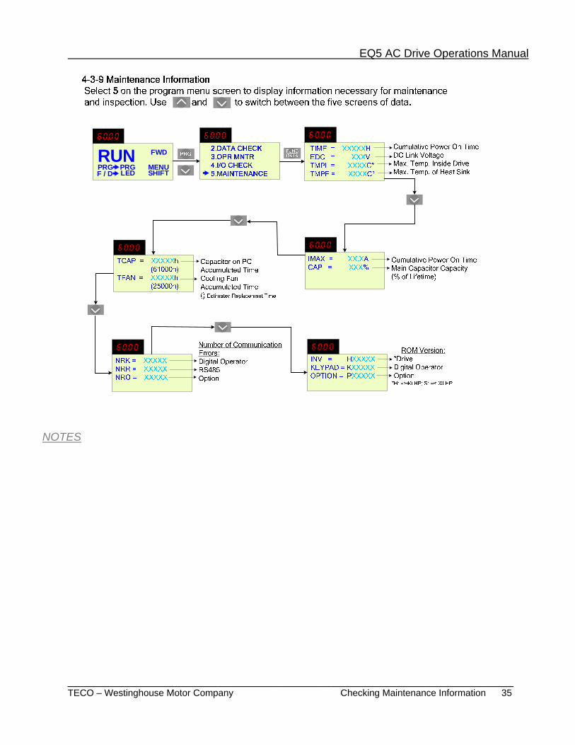
_______________________________________________________________________ TECO – Westinghouse Motor Company Checking Maintenance Information 35
RUN FWD
PRG PRG MENUF / D LED SHIFT
NOTES

EQ5 AC Drive Operations Manual
_______________________________________________________________________ TECO – Westinghouse Motor Company Load Rate Measurement 36
RUN FWD
PRG PRG MENUF / D LED SHIFT
T= 3600s Imax = 0.00A Iave = 0.00ABPave = 0.0%
Measuring Time
Set Measuring Time(0 – 3600 sec.)
T= 600s Imax = 0.00A Iave = 0.00ABPave = 0.0%
Ex.- Set for 600 sec.Start Measuring
T= 150s Imax = 0.00A Iave = 0.00ABPave = 0.0%
Displays remaining measurement time. When = 0 measurement ends.
T= 3600s Imax = 56.4A Iave = 23.5ABPave = 10.4%
Time Returns to Initial Value Maximum Current Average CurrentAverage Braking Power(Motor rated output /100%)
Use these keys to set measuring time
Measurements Displayed
NOTES
EQ5 AC Drive Operations Manual
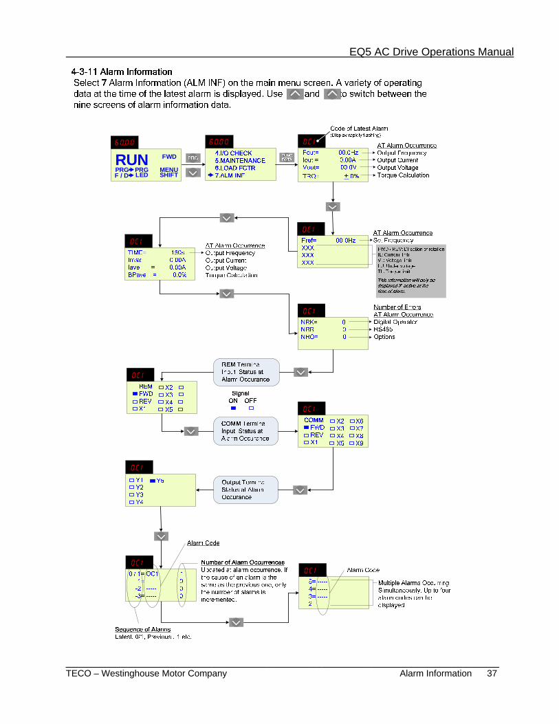
_______________________________________________________________________ TECO – Westinghouse Motor Company Alarm Information 37
RUN FWD
PRG PRG MENUF / D LED SHIFT
EQ5 AC Drive Operations Manual
_______________________________________________________________________ TECO – Westinghouse Motor Company Alarm History & Possible Causes 38
RUN FWD
PRG PRG MENUF / D LED SHIFT
FUNCDATAPRG
5.MAINTENANCE6.LOAD FCTR7.ALM INF8.ALM CAUSE
Latest Alarm
Alarm History
LOW SUP VPWR FAILURE EXCESS LOAD PHASE LOSS
Alarm Code of the selected alarm
Possible cause for alarm occurrence for the selected alarm
FUNCDATA
5= ----- 4= ----- 3= ----- 2= -----
Select an alarmTo be displayed
Display
Simultaneously occurring alarms
Example: Latest alarm LU is selected.
0 / 1= LU 1 -1= ----- 0-2= ----- 0-3= ----- 0
NOTES
EQ5 AC Drive Operations Manual
_______________________________________________________________________ TECO – Westinghouse Motor Company Data Copy & Verify Function 39
Select Data Copy (DATA COPY) on the main menu screen. Press to access the Data Copy (READ) screen. Press to read data from inverter 1. When complete, remove the Digital Operator and attach to inverter 2. Power up and again select 9. Press . On the Data Copy screen press to select (WRITE). Press . When complete the data transfer done.
The (VERIFY) feature which is covered on the next page also mkes it possible to compare and check differences in the data stored in the Digital Operator and the data stored in the inverter.
RUN FWD
PRG PRG MENUF / D LED SHIFT
RUN FWD
PRG PRG MENUF / D LED SHIFT
EQ5 AC Drive Operations Manual
_______________________________________________________________________ TECO – Westinghouse Motor Company Verify Data & Error Processing 40
RUN FWD
PRG PRG MENUF / D LED SHIFT
PRG
6.LOAD FCTR7.ALM INF8.ALM CAUSE9.DATA COPY
1. Data Change Disabled During Operation
If a write operation is attempted during a drive operation, or vice versa, the error message below will appear. After stopping the drive and pressing retry the operation.
Verify Data
COMPLETE
FUNCDATA
FUNCDATA
Error Processing
FUNCDATA
<DATA COPY>30 HP-2
WRITEERR-F25
RESET
<DATA COPY>30 HP-2
READ
<DATA COPY>30 HP-2
VERIFY
<DATA COPY>30 HP-2
VERIFY
<DATA COPY>30 HP-2
WRITEINV RUNNING
2. Memory Error
If a write operation is attempted while data has not been saved (i.e. no data) in the Digital Operator memory during the read mode or when the drive types do not match, the following error message will appear.
<DATA COPY>30 HP-2
WRITEMEMORY ERROR
3. Verify Error
During a data check (Verify) operation, if the data stored in the Digital Operator differs from that stored in the drive, the following error message is displayed to indicate the function number. The data check stops at the first mismatch. To continue the data check press
until another mismatch is displayed or is complete. To stop the data check and switch to another operation, press .RESET
EQ5 AC Drive Operations Manual
_______________________________________________________________________ TECO – Westinghouse Motor Company Alarm Mode 41
5. 5 No. 5 alarm
4. 4 No. 4 alarm
3. 3 No. 3 alarm
2. 2 No. 2 alarm
1. 1 No. 1 alarm (more than two alarms have occurred.)
Blank 0 Latest alarm (only one alarm has occurred / alarm release)
Blank -1 Previous alarm history
Blank -2 Alarm history before previous alarm
Blank -3 Alarm history two times before previous alarm
NOTES
EQ5 AC Drive Operations Manual
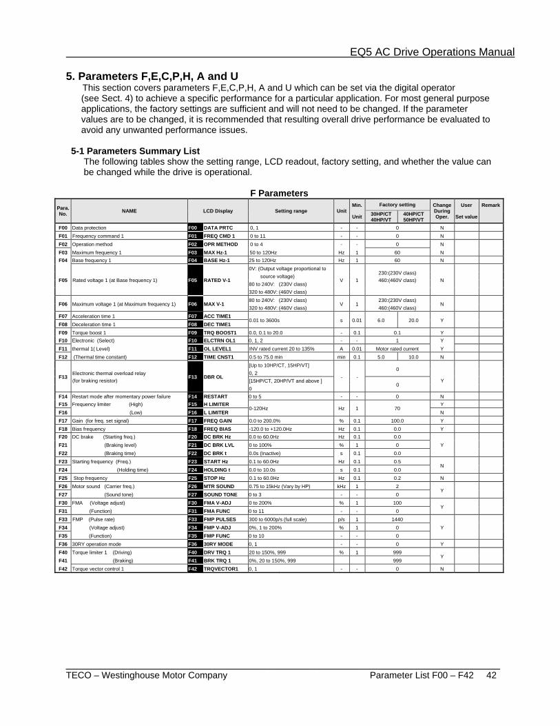
_______________________________________________________________________ TECO – Westinghouse Motor Company Parameter List F00 – F42 42
5. Parameters F,E,C,P,H, A and U This section covers parameters F,E,C,P,H, A and U which can be set via the digital operator (see Sect. 4) to achieve a specific performance for a particular application. For most general purpose applications, the factory settings are sufficient and will not need to be changed. If the parameter values are to be changed, it is recommended that resulting overall drive performance be evaluated to avoid any unwanted performance issues. 5-1 Parameters Summary List The following tables show the setting range, LCD readout, factory setting, and whether the value can be changed while the drive is operational.
F Parameters Para. No. NAME LCD Display Setting range Unit
Min.
Unit
Factory setting ChangeDuring Oper.
User
Set value
Remark 30HP/CT
40HP/VT 40HP/CT 50HP/VT
F00 Data protection F00 DATA PRTC 0, 1 - - 0 N F01 Frequency command 1 F01 FREQ CMD 1 0 to 11 - - 0 N F02 Operation method F02 OPR METHOD 0 to 4 - - 0 N F03 Maximum frequency 1 F03 MAX Hz-1 50 to 120Hz Hz 1 60 N F04 Base frequency 1 F04 BASE Hz-1 25 to 120Hz Hz 1 60 N
F05 Rated voltage 1 (at Base frequency 1) F05 RATED V-1
0V: (Output voltage proportional to
V 1 230:(230V class) 460:(460V class)
N
source voltage) 80 to 240V: (230V class) 320 to 480V: (460V class)
F06 Maximum voltage 1 (at Maximum frequency 1) F06 MAX V-1 80 to 240V: (230V class)
V 1 230:(230V class)
N 320 to 480V: (460V class) 460:(460V class)
F07 Acceleration time 1 F07 ACC TIME1 0.01 to 3600s s 0.01 6.0 20.0 Y
F08 Deceleration time 1 F08 DEC TIME1 F09 Torque boost 1 F09 TRQ BOOST1 0.0, 0.1 to 20.0 - 0.1 0.1 Y F10 Electronic (Select) F10 ELCTRN OL1 0, 1, 2 - - 1 Y F11 thermal 1( Level) F11 OL LEVEL1 INV rated current 20 to 135% A 0.01 Motor rated current Y F12 (Thermal time constant) F12 TIME CNST1 0.5 to 75.0 min min 0.1 5.0 10.0 N
F13
Electronic thermal overload relay (for braking resistor)
F13 DBR OL
[Up to 10HP/CT, 15HP/VT]
- - 0
Y
0, 2 [15HP/CT, 20HP/VT and above ]
0 0
F14 Restart mode after momentary power failure F14 RESTART 0 to 5 - - 0 N F15 Frequency limiter (High) F15 H LIMITER
0-120Hz Hz 1 70 Y
F16 (Low) F16 L LIMITER N F17 Gain (for freq. set signal) F17 FREQ GAIN 0.0 to 200.0% % 0.1 100.0 Y F18 Bias frequency F18 FREQ BIAS -120.0 to +120.0Hz Hz 0.1 0.0 Y F20 DC brake (Starting freq.) F20 DC BRK Hz 0.0 to 60.0Hz Hz 0.1 0.0
Y F21 (Braking level) F21 DC BRK LVL 0 to 100% % 1 0 F22 (Braking time) F22 DC BRK t 0.0s (Inactive) s 0.1 0.0 F23 Starting frequency (Freq.) F23 START Hz 0.1 to 60.0Hz Hz 0.1 0.5
N F24 (Holding time) F24 HOLDING t 0.0 to 10.0s s 0.1 0.0 F25 Stop frequency F25 STOP Hz 0.1 to 60.0Hz Hz 0.1 0.2 N F26 Motor sound (Carrier freq.) F26 MTR SOUND 0.75 to 15kHz (Vary by HP) kHz 1 2
Y F27 (Sound tone) F27 SOUND TONE 0 to 3 - - 0 F30 FMA (Voltage adjust) F30 FMA V-ADJ 0 to 200% % 1 100
Y F31 (Function) F31 FMA FUNC 0 to 11 - - 0 F33 FMP (Pulse rate) F33 FMP PULSES 300 to 6000p/s (full scale) p/s 1 1440
Y F34 (Voltage adjust) F34 FMP V-ADJ 0%, 1 to 200% % 1 0 F35 (Function) F35 FMP FUNC 0 to 10 - - 0 F36 30RY operation mode F36 30RY MODE 0, 1 - - 0 Y F40 Torque limiter 1 (Driving) F40 DRV TRQ 1 20 to 150%, 999 % 1 999
Y F41 (Braking) F41 BRK TRQ 1 0%, 20 to 150%, 999 999 F42 Torque vector control 1 F42 TRQVECTOR1 0, 1 - - 0 N
EQ5 AC Drive Operations Manual
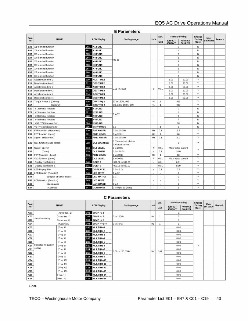
_______________________________________________________________________ TECO – Westinghouse Motor Company Parameter List E01 – E47 & C01 – C19 43
E Parameters Para. No. NAME LCD Display Setting range Unit
Min.
Unit
Factory setting ChangeDuring Oper.
User Set value Remark30HP/CT
40HP/VT 40HP/CT 50HP/VT
E01 X1 terminal function E01 X1 FUNC
0 to 35
-
-
0 N E02 X2 terminal function E02 X2 FUNC 1 N E03 X3 terminal function E03 X3 FUNC 2 N E04 X4 terminal function E04 X4 FUNC 3 N E05 X5 terminal function E05 X5 FUNC 4 N E06 X6 terminal function E06 X6 FUNC 5 N E07 X7 terminal function E07 X7 FUNC 6 N E08 X8 terminal function E08 X8 FUNC 7 N E09 X9 terminal function E09 X9 FUNC 8 N E10 Acceleration time 2 E10 ACC TIME2
0.01 to 3600s s 0.01
6.00 20.00 Y E11 Deceleration time 2 E11 DEC TIME2 6.00 20.00 Y E12 Acceleration time 3 E12 ACC TIME3 6.00 20.00 Y E13 Deceleration time 3 E13 DEC TIME3 6.00 20.00 Y E14 Acceleration time 4 E14 ACC TIME4 6.00 20.00 Y E15 Deceleration time 4 E15 DEC TIME4 6.00 20.00 Y E16 Torque limiter 2 (Driving) E16 DRV TRQ 2 20 to 150%, 999 % 1 999 Y E17 (Braking) E17 BRK TRQ 2 0%, 20 to 150%, 999 % 1 999 Y E20 Y1 terminal function E20 Y1 FUNC
0 to 37
- -
0 N E21 Y2 terminal function E21 Y2 FUNC 1 N E22 Y3 terminal function E22 Y3 FUNC 2 N E23 Y4 terminal function E23 Y4 FUNC 7 N E24 Y5A, Y5C terminal func. E24 Y5 FUNC 10 N E25 Y5 RY operation mode E25 Y5RY MODE 0,1 - 1 0 N E30 FAR function (Hysteresis) E30 FAR HYSTR 0.0 to 10.0Hz Hz 0.1 2.5 Y E31 FDT function (Level) E31 FDT1 LEVEL 0 to 120Hz Hz 1 60 Y E32 Signal (Hysteresis) E32 FDT1 HYSTR 0.0 to 30.0Hz Hz 0.1 1.0 Y
E33 OL1 function(Mode select) E33 OL1 WARNING 0: Thermal calculation
- - 0 Y
1: Output current
E34 Signal (Level) E34 OL1 LEVEL 5 to 200% A 0.01 Motor rated current Y
E35 (Timer) E35 OL1 TIMER 0.0 to 60.0s s 0.1 10.0 E36 FDT2 function (Level) E36 FDT2 LEVEL 0 to120Hz Hz 1 60 Y E37 OL2 function (Level) E37 OL2 LEVEL 5 to 200% A 0.01 Motor rated current Y E40 Display coefficient A E40 COEF A -999.00 to 999.00 - 0.01 0.01 Y E41 Display coefficient B E41 COEF B -999.00 to 999.00 - 0.01 0.00 Y E42 LED Display filter E42 DISPLAY FL 0.0 to 5.0s s 0.1 0.5 Y E43 LED Monitor (Function) E43 LED MNTR 0 to 12 - - 0 Y E44 (Display at STOP mode) E44 LED MNTR2 0, 1 - - 0 Y E45 LCD Monitor (Function) E45 LCD MNTR 0, 1 - - 0 Y E46 (Language) E46 LANGUAGE 0 to 5 - - 1 Y E47 (Contrast) E47 CONTRAST 0 (soft) to 10 (hard) - - 5 Y
C Parameters
Para. No. NAME LCD Display Setting range Unit
Min.
Unit
Factory setting ChangeDuring Oper.
User Set value Remark 30HP/CT
40HP/VT 40HP/CT 50HP/VT
C01
Jump frequency
(Jump freq. 1) C01 JUMP Hz 1 0 to 120Hz Hz 1
0
Y
C02 (Jump freq. 2) C02 JUMP Hz 2 0 C03 (Jump freq. 3) C03 JUMP Hz 3 0 C04 (Hysteresis) C04 JUMP HYSTR 0 to 30Hz Hz 1 3 C05
Multistep frequency setting
(Freq. 1) C05 MULTI Hz-1
0.00 to 120.00Hz
Hz
0.01
0.00 C06 (Freq. 2) C06 MULTI Hz-2 0.00 C07 (Freq. 3) C07 MULTI Hz-3 0.00 C08 (Freq. 4) C08 MULTI Hz-4 0.00 C09 (Freq. 5) C09 MULTI Hz-5 0.00 C10 (Freq. 6) C10 MULTI Hz-6 0.00 C11 (Freq. 7) C11 MULTI Hz-7 0.00 C12 (Freq. 8) C12 MULTI Hz-8 0.00 C13 (Freq. 9) C13 MULTI Hz-9 0.00 C14 (Freq. 10) C14 MULTI Hz-10 0.00 C15 (Freq. 11) C15 MULTI Hz-11 0.00 C16 (Freq. 12) C16 MULTI Hz-12 0.00 C17 (Freq. 13) C17 MULTI Hz-13 0.00 C18 (Freq. 14) C18 MULTI Hz-14 0.00 C19 (Freq. 15) C19 MULTI Hz-15 0.00
Cont.
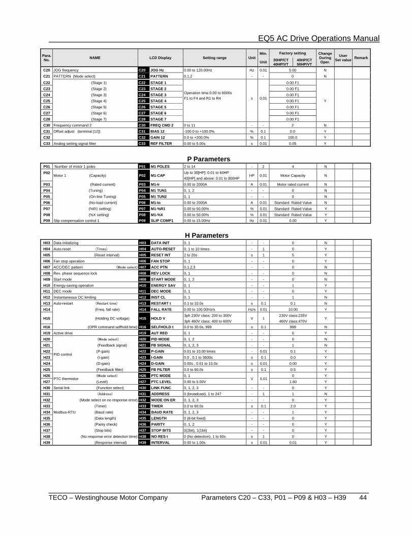
EQ5 AC Drive Operations Manual
_______________________________________________________________________ TECO – Westinghouse Motor Company Parameters C20 – C33, P01 – P09 & H03 – H39 44
Para. No. NAME LCD Display Setting range Unit
Min.
Unit
Factory setting Change During Oper.
User Set value Remark30HP/CT
40HP/VT 40HP/CT 50HP/VT
C20 JOG frequency C20 JOG Hz 0.00 to 120.00Hz Hz 0.01 5.00 N C21 PATTERN (Mode select) C21 PATTERN 0,1,2 - - 0 N
C22 (Stage 1) C22 STAGE 1
Operation time:0.00 to 6000s F1 to F4 and R1 to R4
s
0.01
0.00 F1
Y
C23 (Stage 2) C23 STAGE 2 0.00 F1 C24 (Stage 3) C24 STAGE 3 0.00 F1 C25 (Stage 4) C25 STAGE 4 0.00 F1 C26 (Stage 5) C26 STAGE 5 0.00 F1 C27 (Stage 6) C27 STAGE 6 0.00 F1 C28 (Stage 7) C28 STAGE 7 0.00 F1 C30 Frequency command 2 C30 FREQ CMD 2 0 to 11 - - 2 N C31 Offset adjust (terminal [12]) C31 BIAS 12 -100.0 to +100.0% % 0.1 0.0 Y C32 C32 GAIN 12 0.0 to +200.0% % 0.1 100.0 Y C33 Analog setting signal filter C33 REF FILTER 0.00 to 5.00s s 0.01 0.05 Y
P Parameters P01 Number of motor 1 poles P01 M1 POLES 2 to 14 - 2 4 N
P02
Motor 1 (Capacity) P02 M1-CAP Up to 30[HP]: 0.01 to 60HP
HP 0.01 Motor Capacity N 40[HP] and above: 0.01 to 800HP
P03 (Rated current) P03 M1-Ir 0.00 to 2000A A 0.01 Motor rated current N P04 (Tuning) P04 M1 TUN1 0, 1, 2 - - 0 N P05 (On-line Tuning) P05 M1 TUN2 0, 1 - - 0 N P06 (No-load current) P06 M1-Io 0.00 to 2000A A 0.01 Standard Rated Value N P07 (%R1 setting) P07 M1-%R1 0.00 to 50.00% % 0.01 Standard Rated Value Y P08 (%X setting) P08 M1-%X 0.00 to 50.00% % 0.01 Standard Rated Value Y P09 Slip compensation control 1 P09 SLIP COMP1 0.00 to 15.00Hz Hz 0.01 0.00 Y
H Parameters
H03 Data initializing H03 DATA INIT 0, 1 - - 0 N H04 Auto-reset (Times) H04 AUTO-RESET 0, 1 to 10 times - 1 0 Y H05 (Reset interval) H05 RESET INT 2 to 20s s 1 5 Y H06 Fan stop operation H06 FAN STOP 0, 1 - - 0 Y H07 ACC/DEC pattern (Mode select) H07 ACC PTN 0,1,2,3 - - 0 N H08 Rev. phase sequence lock H08 REV LOCK 0, 1 - - 0 N H09 Start mode H09 START MODE 0, 1, 2 - - 0 N H10 Energy-saving operation H10 ENERGY SAV 0, 1 - - 1 Y H11 DEC mode H11 DEC MODE 0, 1 - - 0 Y H12 Instantaneous OC limiting H12 INST CL 0, 1 - - 1 N H13 Auto-restart (Restart time) H13 RESTART t 0.1 to 10.0s s 0.1 0.1 N H14 (Freq. fall rate) H14 FALL RATE 0.00 to 100.00Hz/s Hz/s 0.01 10.00 Y
H15 (Holding DC voltage) H15 HOLD V 3ph 230V class: 200 to 300V
V 1 230V class:235V
Y
3ph 460V class: 400 to 600V 460V class:470V H16 (OPR command selfhold time) H16 SELFHOLD t 0.0 to 30.0s, 999 s 0.1 999 N H19 Active drive H19 AUT RED 0, 1 - - 0 Y H20
PID control
(Mode select) H20 PID MODE 0, 1, 2 - - 0 N H21 (Feedback signal) H21 FB SIGNAL 0, 1, 2, 3 - - 1 N H22 (P-gain) H22 P-GAIN 0.01 to 10.00 times - 0.01 0.1 Y H23 (I-gain) H23 I-GAIN 0.0 , 0.1 to 3600s s 0.1 0.0 Y H24 (D-gain) H24 D-GAIN 0.00s , 0.01 to 10.0s s 0.01 0.00 Y H25 (Feedback filter) H25 FB FILTER 0.0 to 60.0s s 0.1 0.5 Y H26
PTC thermistor (Mode select) H26 PTC MODE 0, 1
V 0.01 0 Y
H27 (Level) H27 PTC LEVEL 0.00 to 5.00V 1.60 Y H30 Serial link (Function select) H30 LINK FUNC 0, 1, 2, 3 - - 0 Y H31 (Address) H31 ADDRESS 0 (broadcast), 1 to 247 - 1 1 N H32 (Mode select on no response error) H32 MODE ON ER 0, 1, 2, 3 - - 0 Y H33 (Timer) H33 TIMER 0.0 to 60.0s s 0.1 2.0 Y H34 Modbus-RTU (Baud rate) H34 BAUD RATE 0, 1, 2, 3 - - 1 Y H35 (Data length) H35 LENGTH 0 (8-bit fixed) - - 0 Y H36 (Parity check) H36 PARITY 0, 1, 2 - - 0 Y H37 (Stop bits) H37 STOP BITS 0(2bit), 1(1bit) - - 0 Y H38 (No response error detection time) H38 NO RES t 0 (No detection), 1 to 60s s 1 0 Y H39 (Response interval) H39 INTERVAL 0.00 to 1.00s s 0.01 0.01 Y
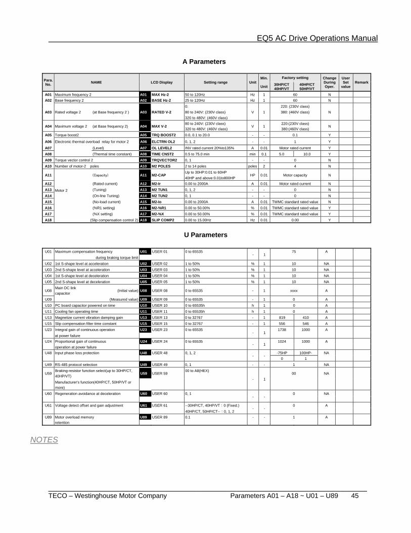
EQ5 AC Drive Operations Manual
_______________________________________________________________________ TECO – Westinghouse Motor Company Parameters A01 – A18 ~ U01 – U89 45
A Parameters
Para. No. NAME LCD Display Setting range Unit
Min.
Unit
Factory setting Change During Oper.
User Set
value Remark30HP/CT
40HP/VT 40HP/CT 50HP/VT
A01 Maximum frequency 2 A01 MAX Hz-2 50 to 120Hz Hz 1 60 N A02 Base frequency 2 A02 BASE Hz-2 25 to 120Hz Hz 1 60 N
A03 Rated voltage 2 (at Base frequency 2 ) A03 RATED V-2 0:
V 1 220: (230V class)
N
80 to 240V: (230V class) 380: (460V class) 320 to 480V: (460V class)
A04 Maximum voltage 2 (at Base frequency 2) A04 MAX V-2 80 to 240V: (230V class)
V 1 220:(230V class)
N
320 to 480V: (460V class) 380:(460V class)
A05 Torque boost2 A05 TRQ BOOST2 0.0, 0.1 to 20.0 - - 0.1 Y
A06 Electronic thermal overload relay for motor 2 A06 ELCTRN OL2 0, 1, 2 - - 1 Y
A07 (Level) A07 OL LEVEL2 INV rated current 20%to135% A 0.01 Motor rated current Y A08 (Thermal time constant) A08 TIME CNST2 0.5 to 75.0 min min 0.1 5.0 10.0 Y A09 Torque vector control 2 A09 TRQVECTOR2 0, 1 - - 0 N A10 Number of motor-2 poles A10 M2 POLES 2 to 14 poles poles 2 4 N
A11
Motor 2
(Capacity) A11 M2-CAP Up to 30HP:0.01 to 60HP
HP 0.01 Motor capacity N 40HP and above:0.01to800HP
A12 (Rated current) A12 M2-Ir 0.00 to 2000A A 0.01 Motor rated current N A13 (Tuning) A13 M2 TUN1 0, 1, 2 - - 0 N A14 (On-line Tuning) A14 M2 TUN2 0, 1 - - 0 N A15 (No-load current) A15 M2-Io 0.00 to 2000A A 0.01 TWMC standard rated value N A16 (%R1 setting) A16 M2-%R1 0.00 to 50.00% % 0.01 TWMC standard rated value Y A17 (%X setting) A17 M2-%X 0.00 to 50.00% % 0.01 TWMC standard rated value Y A18 (Slip compensation control 2) A18 SLIP COMP2 0.00 to 15.00Hz Hz 0.01 0.00 Y
U Parameters
U01 Maximum compensation frequency U01 USER 01 0 to 65535
- 1 75 A
during braking torque limit
U02 1st S-shape level at acceleration U02 USER 02 1 to 50% % 1 10 NA U03 2nd S-shape level at acceleration U03 USER 03 1 to 50% % 1 10 NA U04 1st S-shape level at deceleration U04 USER 04 1 to 50% % 1 10 NA U05 2nd S-shape level at deceleration U05 USER 05 1 to 50% % 1 10 NA
U08 Main DC link capacitor
(Initial value) U08 USER 08 0 to 65535 - 1 xxxx A
U09 (Measured value) U09 USER 09 0 to 65535 - 1 0 A U10 PC board capacitor powered on time U10 USER 10 0 to 65535h h 1 0 A U11 Cooling fan operating time U11 USER 11 0 to 65535h h 1 0 A U13 Magnetize current vibration damping gain U13 USER 13 0 to 32767 - 1 819 410 A U15 Slip compensation filter time constant U15 USER 15 0 to 32767 - 1 556 546 A U23 Integral gain of continuous operation U23 USER 23 0 to 65535
- 1 1738 1000 A
at power failure
U24 Proportional gain of continuous U24 USER 24 0 to 65535 - 1
1024 1000 A
operation at power failure U48 Input phase loss protection U48 USER 48 0, 1, 2
- - -75HP 100HP- NA
0 1
U49 RS-485 protocol selection U49 USER 49 0, 1 - - 1 NA
U59 Braking-resistor function select(up to 30HP/CT, 40HP/VT)
U59 USER 59 00 to A8(HEX)
- 1 00 NA
Manufacturer's function(40HP/CT, 50HP/VT or more)
U60 Regeneration avoidance at deceleration U60 USER 60 0, 1 - -
0 NA
U61 Voltage detect offset and gain adjustment U61 USER 61 --30HP/CT, 40HP/VT:0 (Fixed.)
- - 0 A
40HP/CT, 50HP/CT--:0, 1, 2
U89 Motor overload memory U89 USER 89 0.1 - - 1 A retention
NOTES
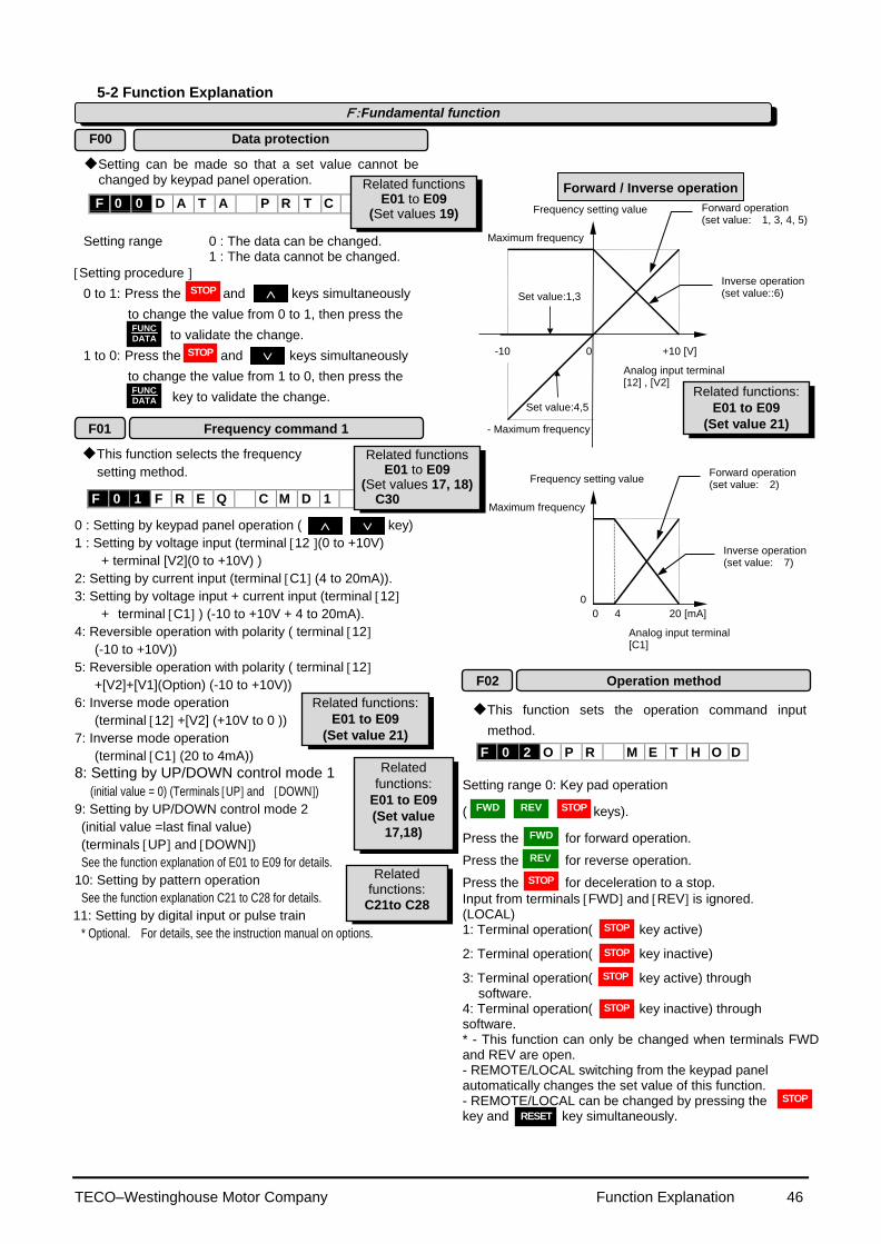
TECO–Westinghouse Motor Company Function Explanation 46
5-2 Function Explanation Setting can be made so that a set value cannot be
changed by keypad panel operation. Setting range 0 : The data can be changed. 1 : The data cannot be changed.
Setting procedure
0 to 1: Press the and keys simultaneously
to change the value from 0 to 1, then press the
to validate the change.
1 to 0: Press the and keys simultaneously
to change the value from 1 to 0, then press the
key to validate the change.
This function selects the frequency
setting method.
0 : Setting by keypad panel operation ( key)
1 : Setting by voltage input (terminal 12 (0 to +10V)
+ terminal [V2](0 to +10V) )
2: Setting by current input (terminal C1 (4 to 20mA)).
3: Setting by voltage input + current input (terminal 12
+ terminal C1 ) (-10 to +10V + 4 to 20mA).
4: Reversible operation with polarity ( terminal 12
(-10 to +10V))
5: Reversible operation with polarity ( terminal 12
+[V2]+[V1](Option) (-10 to +10V))
6: Inverse mode operation
(terminal 12 +[V2] (+10V to 0 ))
7: Inverse mode operation
(terminal C1 (20 to 4mA))
8: Setting by UP/DOWN control mode 1
(initial value = 0) (Terminals UP and DOWN)
9: Setting by UP/DOWN control mode 2
(initial value =last final value)
(terminals UP and DOWN)
See the function explanation of E01 to E09 for details.
10: Setting by pattern operation
See the function explanation C21 to C28 for details.
11: Setting by digital input or pulse train
* Optional. For details, see the instruction manual on options.
Set value:1,3
Set value:4,5
-10 0 +10 [V]
- Maximum frequency
Maximum frequency
Frequency setting value
Analog input terminal [12] , [V2]
Inverse operation (set value::6)
Forward operation (set value: 1, 3, 4, 5)
0 4 20 [mA]
Maximum frequency
0
Frequency setting value
Analog input terminal [C1]
Inverse operation (set value: 7)
Forward operation (set value: 2)
This function sets the operation command input
method.
Setting range 0: Key pad operation
( keys).
Press the for forward operation.
Press the for reverse operation.
Press the for deceleration to a stop.
Input from terminals FWD and REV is ignored. (LOCAL) 1: Terminal operation( key active) 2: Terminal operation( key inactive) 3: Terminal operation( key active) through
software. 4: Terminal operation( key inactive) through software. * - This function can only be changed when terminals FWD and REV are open. - REMOTE/LOCAL switching from the keypad panel automatically changes the set value of this function. - REMOTE/LOCAL can be changed by pressing the key and key simultaneously.
FWD FWD
F:Fundamental function
F00 Data protection
FWD FWD
FWD FWD
FWD FWD
F01 Frequency command 1
F02 Operation method
Related
functions:
E01 to E09
(Set value
17,18)
Forward / Inverse operation
Related functions:
C21to C28
Related functions:
E01 to E09
(Set value 21)
F 0 0 D A T A P R T C
Related functions E01 to E09
(Set values 19)
F 0 1 F R E Q C M D 1
Related functions E01 to E09
(Set values 17, 18) C30
F 0 2 O P R M E T H O D
Related functions:
E01 to E09
(Set value 21)
FUNC DATA
FUNC DATA
FWD REV
STOP
STOP
STOP
FWD
REV
STOP
STOP
RESET
STOP
STOP
STOP
STOP

TECO–Westinghouse Motor Company Function Explanation 47
JOG
SS1
SS2
SS4
SS8
JOG
Hz2/PID
12
V1
C1
Hz2/Hz1
LE
V2
Option
PID control
H25
H24
H23
H22
H20
H21
F18 F17
C08
C07
C06
H30
C30 F01
C05
C33
+
+
+ + #1,#5
#8,#9
#6
#7
#3
#2
#1,#2,#3,#6,#7
#4
#0
Bias frequency
Frequency setting
Analog input filter
Frequency setting by keypad panel Feedback filter
Feedback selection
Differential
Integral
Proportional
Operation selection
Gain
Negative polarity prevention
Multistep frequency switching
Lower-limit frequency
Maximum frequency
Upper-limit frequency
Set frequency
value
Multistep frequencies 1 to 15
Limit signal
Limiter processing
Jump frequency
JOG frequency
Set frequency value
by Link function
D/I or pulse train (optional)
UP/DOWN control
Inverse
operation
Forward/ Reverse operation
Inverse
operation
UP
Pattern operation control
DOWN
C12
C11
C10
C09
C16
C15
C14
C13
C04
C03
F16
A01 F03
F15
C01
C02
C20
C19
C18
C17
Fre
qu
en
cy s
ett
ing
sig
na
ls
#11
#10
C24
C28
C27
C23
C26
C25
C22
IVS
Switching command
C21
#5
+
+
C31 C32
Gain Bias
Note: The numbers marked "#" means the setting value of each functions.
Frequency setting block diagram

TECO–Westinghouse Motor Company Function Explanation 48
This function sets the maximum output frequency for
motor 1. This is a function for motor 1.
Setting range EQ5: 50 to 120Hz
Setting a value higher than the rated value of the device to be driven may damage the motor or machine. Match the rating of the device.
This function sets the maximum output frequency in the
constant-torque range of motor 1 or the output frequency at the rated output voltage. Match the rating of the motor.
This is a function for motor 1.
Setting range EQ5: 25 to 120Hz
Note: When the set value of base frequency 1 is higher than that of maximum output frequency 1, the output voltage does not increase to the rated voltage because the maximum frequency limits the output frequency.
Output frequency
F06 Maximum
output voltage 1
Output
voltage
F05 Rated voltage 1
0 F04 Base
frequency 1F03 Maximum
output frequency
Constant-torque range
This function sets the rated value of the voltage output
to motor 1. Note that a voltage greater than the supply (input) voltage cannot be output.
This is a function for motor 1.
Setting range 230 V series: 0, 80 to 240V 460 V series: 0, 320 to 480V Value 0 terminates operation of the voltage regulation function, thereby resulting in the output of a voltage proportional to the supply voltage.
Note: When the set value of rated voltage 1 exceeds maximum output voltage 1, the output voltage does not increase to the rated voltage because the maximum output voltage limits the output voltage. This function sets the maximum value of the voltage
output for motor 1. Note that a voltage higher than the supply (input) voltage cannot be output.
This is a function for motor 1.
Setting range 230 V series: 80 to 240V 460 V series: 320 to 480V
Note: When the set value of rated voltage 1 (F05) to "0", this function is invalid.
This function sets the acceleration time for the output frequency from startup to maximum frequency and the deceleration time from maximum frequency to operation stop.
Setting range Acceleration time 1: 0.01 to 3,600 seconds Deceleration time 1: 0.01 to 3,600 seconds
Set acceleration and deceleration times with respect to maximum frequency. The relationship between the set frequency value and acceleration/deceleration times is as follows:
Set frequency = maximum frequency The actual operation time matches the set value.
Outp
ut fr
equency
Acceleration time
Set frequency
Time
Deceleration time
Maximum frequency
Set frequency < maximum frequency The actual operation time differs from the set value.
Acceleration(deceleration) operation time = set value x (set frequency/maximum frequency)
Acceleration
operation time
Time
Set frequency
Deceleration timeAcceleration time
Deceleration
operation time
Outp
ut fr
equency Maximum frequency
Note: If the set acceleration and deceleration times are too short even though the resistance torque and moment of inertia of the load are great, the torque limiting function or stall prevention function becomes activated, thereby prolonging the operation time beyond that stated above.
F04 Base frequency 1
F03 Maximum frequency 1
F05 Rated voltage 1
F06 Maximum voltage 1
F07 Acceleration time 1
F08 Deceleration time 1
STOP FWD
STOP FWD
F 0 3 M A X H z - 1
F 0 7 A C C T I M E 1
F 0 8 D E C T I M E 1
F 0 4 B A S E H z - 1
F 0 5 R A T E D V - 1
F 0 6 M A X V - 1
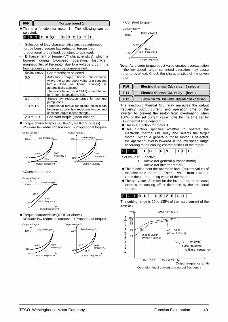
TECO–Westinghouse Motor Company Function Explanation 49
This is a function for motor 1. The following can be selected:
-- Selection of load characteristics such as automatic
torque boost, square law reduction torque load, proportional torque load, constant torque load.
-- Enhancement of torque (V/f characteristics), which is lowered during low-speed operation. Insufficient magnetic flux of the motor due to a voltage drop in the low-frequency range can be compensated.
Setting range Characteristics selected
0.0 Automatic torque boost characteristic where the torque boost value of a constant torque load (a linear change) is automatically adjusted. The motor tuning (P04 / A13) should be set to "2" for this function is valid.
0.1 to 0.9 Square law reduction torque for fan and pump loads.
1.0 to 1.9 Proportional torque for middle class loads between square law reduction torque and constant torque (linear change)
2.0 to 20.0 Constant torque (linear change)
Torque characteristics(30HP/CT, 40HP/VT or less) <Square law reduction torque> <Proportional torque>
100%
Output frequency f
#0.1
#0.9
0
17%
Rated voltage 1
Output voltage V
17%
Output frequency f
100%
Base
frequency 1
#1.0
#1.9
0
Output voltage V
Rated voltage 1
Base
frequency 1
<Constant torque>
100%
Output frequency f
Base
frequency 1#2.0
#20.0
0
23%
Rated voltage 1
Output voltage V
Torque characteristics(40HP or above)
<Square law reduction torque> <Proportional torque>
100%
Output frequency f
#0.1
#0.9
0
18%
Rated voltage 1
Output voltage V
18%
Output frequency f
100%
Base
frequency 1
#1.0
#1.9
0
Output voltage V
Rated voltage 1
Base
frequency 1
<Constant torque>
100%
Output frequency f
Base
frequency 1#2.0
#20.0
0
10%
Rated voltage 1
Output voltage V
Note: As a large torque boost value creates overexcitation in the low-speed range, continued operation may cause motor to overheat. Check the characteristics of the driven motor. The electronic thermal O/L relay manages the output frequency, output current, and operation time of the inverter to prevent the motor from overheating when 150% of the set current value flows for the time set by F12 (thermal time constant). This is a function for motor 1. This function specifies whether to operate the
electronic thermal O/L relay and selects the target motor. When a general-purpose motor is selected, the operation level is lowered in the low speed range according to the cooling characteristics of the motor.
Set value 0: Inactive 1: Active (for general-purpose motor) 2: Active (for inverter motor) This function sets the operation level (current value) of
the electronic thermal. Enter a value from 1 to 1.1 times the current rating value of the motor.
The set value "2" is set for the inverter motor because there is no cooling effect decrease by the rotational speed.
The setting range is 20 to 135% of the rated current of the inverter.
Output frequency f0 (Hz)
Ope
ration
level curr
en
t (%
)
85
54
Fe x 0.33 Fe x 0.83 fe
0.2 to 22kW
30 to 45kW
90 95
100
69
When F10 = 2 (%)
(When F10 = 1)
(When F10 = 1)
Operation level current and output frequency
fe= fb (fb60Hz)
60Hz (fb60Hz)
fb:Base frequency
F10
Electric thermal O/L relay (Thermal time constant)
Electric thermal O/L relay (level)
Electric thermal O/L relay ( select)
F11
F12
F09 Torque boost 1
F 1 0 E L C T R N O L 1
F 1 1 O L L E V E L 1
F 0 9 T R Q B O O S T 1
0.25 to 30HP (When F10 = 1)
40 to 60HP (When F10 = 1)
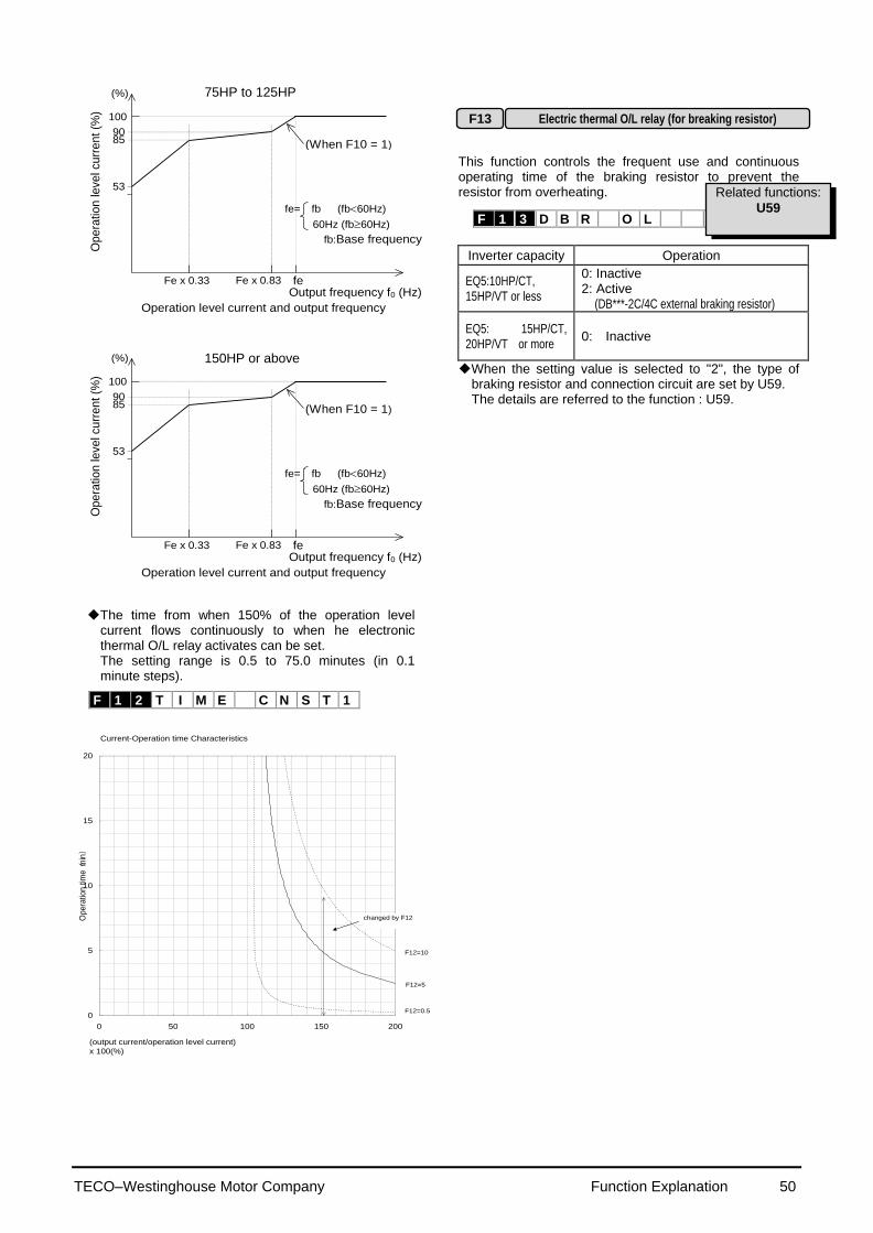
TECO–Westinghouse Motor Company Function Explanation 50
Output frequency f0 (Hz)
Op
era
tio
n le
ve
l cu
rre
nt
(%)
53
Fe x 0.33 Fe x 0.83 fe
100
110kW or above (%)
Operation level current and output frequency
fe= fb (fb60Hz)
60Hz (fb60Hz)
fb:Base frequency
(When F10 = 1) 85 90
Output frequency f0 (Hz)
Op
era
tio
n le
ve
l cu
rre
nt
(%)
53
Fe x 0.33 Fe x 0.83 fe
100
110kW or above (%)
Operation level current and output frequency
fe= fb (fb60Hz)
60Hz (fb60Hz)
fb:Base frequency
(When F10 = 1) 85 90
The time from when 150% of the operation level
current flows continuously to when he electronic thermal O/L relay activates can be set. The setting range is 0.5 to 75.0 minutes (in 0.1 minute steps).
0
5
10
15
20
0 50 100 150 200
Opera
tion t
ime(m
in)
F12=0.5
F12=10
F12=5
changed by F12
(output current/operation level current)
x 100(%)
Current-Operation time Characteristics
This function controls the frequent use and continuous operating time of the braking resistor to prevent the resistor from overheating.
Inverter capacity Operation
EQ5:10HP/CT, 15HP/VT or less
0: Inactive 2: Active
(DB***-2C/4C external braking resistor)
EQ5: 15HP/CT, 20HP/VT or more
0: Inactive
When the setting value is selected to "2", the type of braking resistor and connection circuit are set by U59. The details are referred to the function : U59.
F 1 2 T I M E C N S T 1
Electric thermal O/L relay (for breaking resistor) F13
F 1 3 D B R O L
Related functions:
U59
75HP to 125HP
150HP or above
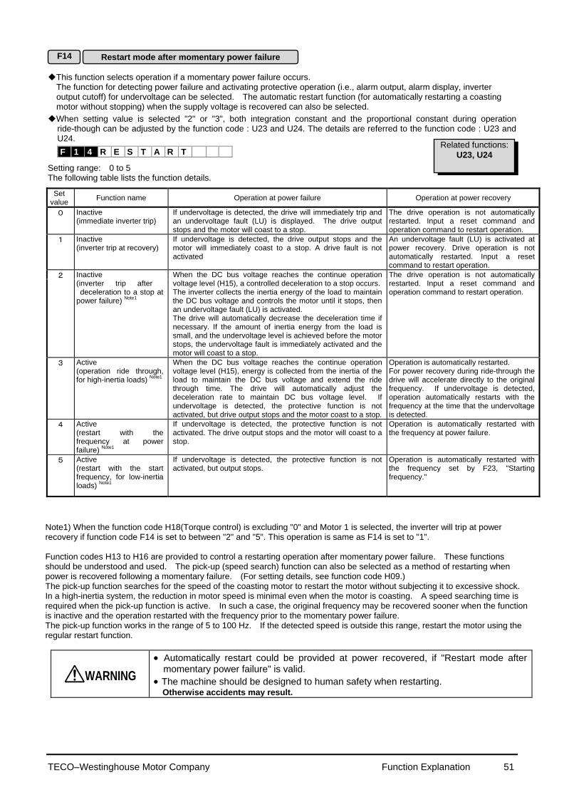
TECO–Westinghouse Motor Company Function Explanation 51
This function selects operation if a momentary power failure occurs. The function for detecting power failure and activating protective operation (i.e., alarm output, alarm display, inverter output cutoff) for undervoltage can be selected. The automatic restart function (for automatically restarting a coasting motor without stopping) when the supply voltage is recovered can also be selected.
When setting value is selected "2" or "3", both integration constant and the proportional constant during operation ride-though can be adjusted by the function code : U23 and U24. The details are referred to the function code : U23 and U24.
Setting range: 0 to 5 The following table lists the function details.
F14
Restart mode after momentary power failure
Set value
Function name Operation at power failure Operation at power recovery
0 Inactive (immediate inverter trip)
If undervoltage is detected, the drive will immediately trip and an undervoltage fault (LU) is displayed. The drive output stops and the motor will coast to a stop.
The drive operation is not automatically restarted. Input a reset command and operation command to restart operation.
1 Inactive (inverter trip at recovery)
If undervoltage is detected, the drive output stops and the motor will immediately coast to a stop. A drive fault is not activated
An undervoltage fault (LU) is activated at power recovery. Drive operation is not automatically restarted. Input a reset command to restart operation.
2 Inactive (inverter trip after deceleration to a stop at power failure)
Note1
When the DC bus voltage reaches the continue operation voltage level (H15), a controlled deceleration to a stop occurs. The inverter collects the inertia energy of the load to maintain the DC bus voltage and controls the motor until it stops, then an undervoltage fault (LU) is activated. The drive will automatically decrease the deceleration time if necessary. If the amount of inertia energy from the load is small, and the undervoltage level is achieved before the motor stops, the undervoltage fault is immediately activated and the motor will coast to a stop.
The drive operation is not automatically restarted. Input a reset command and operation command to restart operation.
3 Active (operation ride through, for high-inertia loads)
Note1
When the DC bus voltage reaches the continue operation voltage level (H15), energy is collected from the inertia of the load to maintain the DC bus voltage and extend the ride through time. The drive will automatically adjust the deceleration rate to maintain DC bus voltage level. If undervoltage is detected, the protective function is not activated, but drive output stops and the motor coast to a stop.
Operation is automatically restarted. For power recovery during ride-through the drive will accelerate directly to the original frequency. If undervoltage is detected, operation automatically restarts with the frequency at the time that the undervoltage is detected.
4 Active (restart with the frequency at power failure)
Note1
If undervoltage is detected, the protective function is not activated. The drive output stops and the motor will coast to a stop.
Operation is automatically restarted with the frequency at power failure.
5 Active (restart with the start frequency, for low-inertia loads)
Note1
If undervoltage is detected, the protective function is not activated, but output stops.
Operation is automatically restarted with the frequency set by F23, "Starting frequency."
Note1) When the function code H18(Torque control) is excluding "0" and Motor 1 is selected, the inverter will trip at power recovery if function code F14 is set to between "2" and "5". This operation is same as F14 is set to "1". Function codes H13 to H16 are provided to control a restarting operation after momentary power failure. These functions should be understood and used. The pick-up (speed search) function can also be selected as a method of restarting when power is recovered following a momentary failure. (For setting details, see function code H09.) The pick-up function searches for the speed of the coasting motor to restart the motor without subjecting it to excessive shock. In a high-inertia system, the reduction in motor speed is minimal even when the motor is coasting. A speed searching time is required when the pick-up function is active. In such a case, the original frequency may be recovered sooner when the function is inactive and the operation restarted with the frequency prior to the momentary power failure. The pick-up function works in the range of 5 to 100 Hz. If the detected speed is outside this range, restart the motor using the regular restart function.
WARNING
Automatically restart could be provided at power recovered, if "Restart mode after momentary power failure" is valid.
The machine should be designed to human safety when restarting. Otherwise accidents may result.
F 1 4 R E S T A R T
Related functions:
U23, U24

TECO–Westinghouse Motor Company Function Explanation 52
Set value : 0
Main circuit DCvoltage
Power failure
Under voltage
Power recovery
Time
Outputfrequency
ON
ON
H15Operation continuation level
LV trip
Set value : 1
Main circuit DCvoltage
Outputfrequency
LV trip
Under voltage
Time
Set value : 2
Main circuit DCvoltage
Outputfrequency
LV tripON
Time
Set value : 3
Power failure Power recovery
H15Operation continuation level
Outputfrequency
(motor speed)
Main circuit DCvoltage
LV trip
Output
Acceleration
Under voltage
Synchroni- zation
ON
H13:Waiting time
Main circuit DCvoltage
Set value : 4
Outputfrequency
(motor speed)
LV trip
Output
(terminals Y1 to Y5)
Set value : 5
Main circuit DCvoltage Under voltage
Outputfrequency
(motor speed)
LV trip
Output
H13:Waiting time
(terminals Y1 to Y5)
(terminals Y1 to Y5)
Note : Dotted-dashed lines indicate motor speed.
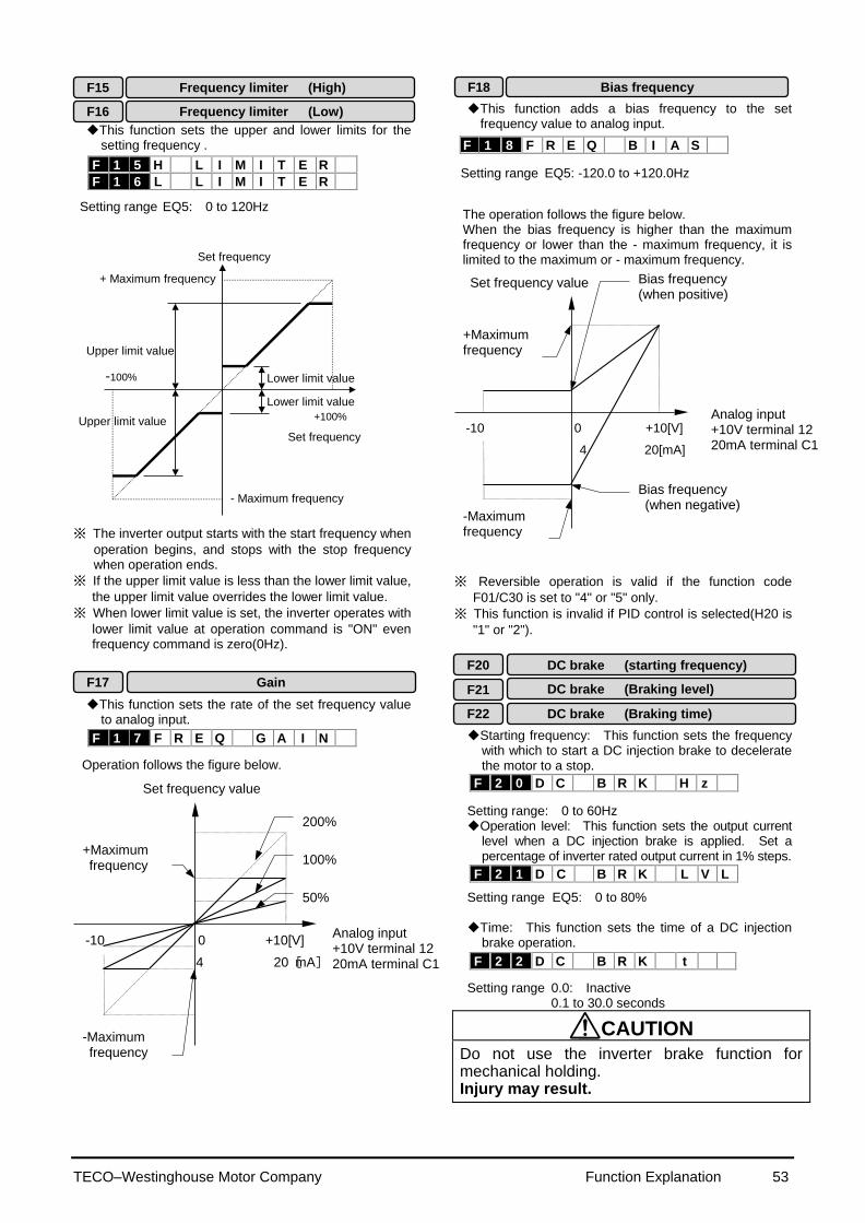
TECO–Westinghouse Motor Company Function Explanation 53
This function sets the upper and lower limits for the
setting frequency .
Setting range EQ5: 0 to 120Hz
Upper limit value
Lower limit value
Lower limit value
Upper limit value
Set frequency
Set frequency
+ Maximum frequency
- Maximum frequency
+100%
-100%
※ The inverter output starts with the start frequency when
operation begins, and stops with the stop frequency when operation ends.
※ If the upper limit value is less than the lower limit value,
the upper limit value overrides the lower limit value.
※ When lower limit value is set, the inverter operates with
lower limit value at operation command is "ON" even frequency command is zero(0Hz).
This function sets the rate of the set frequency value
to analog input.
Operation follows the figure below.
4 20[mA]
-10 0 +10[V]
Set frequency value
Analog input +10V terminal 12 20mA terminal C1
200%
100%
50%
+Maximum frequency
-Maximum frequency
This function adds a bias frequency to the set frequency value to analog input.
Setting range EQ5: -120.0 to +120.0Hz
The operation follows the figure below. When the bias frequency is higher than the maximum frequency or lower than the - maximum frequency, it is limited to the maximum or - maximum frequency.
4 20[mA]
-10 0 +10[V]
Set frequency value
Analog input +10V terminal 12 20mA terminal C1
Bias frequency (when positive)
Bias frequency (when negative)
+Maximum frequency
-Maximum frequency
※ Reversible operation is valid if the function code
F01/C30 is set to "4" or "5" only.
※ This function is invalid if PID control is selected(H20 is
"1" or "2"). Starting frequency: This function sets the frequency
with which to start a DC injection brake to decelerate the motor to a stop.
Setting range: 0 to 60Hz Operation level: This function sets the output current
level when a DC injection brake is applied. Set a percentage of inverter rated output current in 1% steps.
Setting range EQ5: 0 to 80% Time: This function sets the time of a DC injection
brake operation. Setting range 0.0: Inactive
0.1 to 30.0 seconds
CAUTION Do not use the inverter brake function for mechanical holding. Injury may result.
F20 DC brake (starting frequency)
DC brake (Braking level)
DC brake (Braking time)
F21
F22
F18 Bias frequency Frequency limiter (High) F15
F16 Frequency limiter (Low)
F 1 8 F R E Q B I A S
F 1 5 H L I M I T E R
F 1 6 L L I M I T E R
F 1 7 F R E Q G A I N
F 2 0 D C B R K H z
F 2 1 D C B R K L V L
F 2 2 D C B R K t
F17 Gain

TECO–Westinghouse Motor Company Function Explanation 54
Holding time
Time
Forward rotation
Starting frequency Stopping frequency
Output frequency
The starting frequency can be set to reserve the torque at startup and can be sustained until the magnetic flux of the motor is being established. Frequency: This function sets the frequency at startup.
Setting range: 0.1 to 60Hz Holding time: This function sets the holding time
during which the start frequency is sustained at startup. Set values: 0.1 to 10.0 seconds
The holding time does not apply at the time of switching
between forward and reverse.
The holding time is not included in the acceleration time.
The holding time also applies when pattern operation
(C21) is selected. The holding time is included in the timer value. This function sets the frequency at stop.
Setting range: 0.0 to 60.0Hz The operation does not start when the starting frequency is less than the stopping frequency or when the setting frequency is less than the stopping frequency.
This function adjusts the carrier frequency, correct
adjustment of which prevents resonance with the machine system, reduces motor and inverter noise, and also reduces leakage current from output circuit wiring.
Nominal applied motor Setting range
EQ5
30HP/CT or less 40HP/VT or less
0.75 to 15kHz
40HP/CT to 100HP/CT 50HP/VT to 125HP/VT
0.75 to 10kHz
125HP/CT or more 150HP/VT or more
0.75 to 6kHz
Carrier frequency Low High
Motor noise High Low
Output current waveform Bad Good
Leakage current Small amount Large amount
Noise occurrence Extremely low High
The tone of motor noise can be altered when the carrier frequency is 7kHz or lower. Use this function as required.
Setting range: 0 , 1, 2 , 3 Monitor data (e.g.,output frequency, output current) can be output to terminal FMA as a DC voltage. The amplitude of the output can also be adjusted. This function adjusts the voltage value of the monitor
item selected in F31 when the monitor amount is 100%. A value from 0 to 200 (%) can be set in 1% steps.
Setting range: 0 to 200% This function selects the monitor item to be output to
terminal FMA.
Set value
Monitor item Definition of 100% monitor amount
0 Output frequency 1 (before slip compensation)
Maximum output frequency
1 Output frequency 2 (after slip compensation)
Maximum output frequency
2 Output current Rated output current of inverter x 2
3 Output voltage 230V series: 250V 460V series: 500V
4 Output torque Rated torque of motor x 2
5 Load rate Rated load of motor x 2
6 Power consumption Rated output of inverter x 2
7 PID feedback amount Feedback amount of 100%
8 PG feedback amount (only when option is installed)
Synchronous speed at maximum frequency
9 DC link circuit voltage 230V series: 500V 460V series: 1,000V
10 Universal AO 0 to 10V output through communication and not related to inverter operation.
※The power consumption shows "0" during regenerative load.
F30:200% Higher than 10V
F30:0%
F30:50% 5V
10V F30:100%
100% 50%
FM
A te
rmin
al
outp
ut
voltage
F23
F24
Starting frequency (frequency)
Start frequency (Holding time)
F25 Stop frequency
F30 FMA (voltage adjust)
FMA (function) F31
F26 Motor sound (carrier frequency)
F27 Motor sound (sound tone)
Notes: 1. Reducing the set value adversely affects the output current
waveform (i.e., higher harmonics), increases motor loss, and raises motor temperature. For example, at 0.75 kHz, reduce the motor torque by about15%.
2 Increasing the set value increases inverter loss and increases the inverter temperature.
F 2 3 S T A R T H z
F 2 4 H O L D I N G t
F 2 5 S T O P H z
F 2 6 M T R S O U N D
F 2 7 M T R T O N E
F 3 0 F M A V - A D J
F 3 1 F M A F U N C
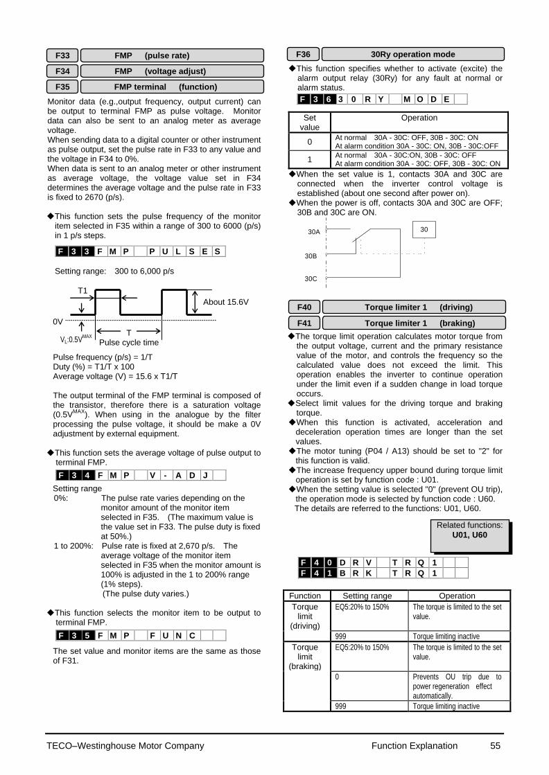
TECO–Westinghouse Motor Company Function Explanation 55
Monitor data (e.g.,output frequency, output current) can be output to terminal FMP as pulse voltage. Monitor data can also be sent to an analog meter as average voltage. When sending data to a digital counter or other instrument as pulse output, set the pulse rate in F33 to any value and the voltage in F34 to 0%. When data is sent to an analog meter or other instrument as average voltage, the voltage value set in F34 determines the average voltage and the pulse rate in F33 is fixed to 2670 (p/s). This function sets the pulse frequency of the monitor
item selected in F35 within a range of 300 to 6000 (p/s) in 1 p/s steps.
Setting range: 300 to 6,000 p/s Pulse frequency (p/s) = 1/T Duty (%) = T1/T x 100 Average voltage (V) = 15.6 x T1/T The output terminal of the FMP terminal is composed of the transistor, therefore there is a saturation voltage (0.5V
MAX). When using in the analogue by the filter
processing the pulse voltage, it should be make a 0V adjustment by external equipment. This function sets the average voltage of pulse output to
terminal FMP.
Setting range 0%: The pulse rate varies depending on the
monitor amount of the monitor item selected in F35. (The maximum value is the value set in F33. The pulse duty is fixed at 50%.)
1 to 200%: Pulse rate is fixed at 2,670 p/s. The average voltage of the monitor item selected in F35 when the monitor amount is 100% is adjusted in the 1 to 200% range (1% steps). (The pulse duty varies.)
This function selects the monitor item to be output to
terminal FMP.
The set value and monitor items are the same as those of F31.
This function specifies whether to activate (excite) the
alarm output relay (30Ry) for any fault at normal or alarm status.
Set value
Operation
0 At normal 30A - 30C: OFF, 30B - 30C: ON At alarm condition 30A - 30C: ON, 30B - 30C:OFF
1 At normal 30A - 30C:ON, 30B - 30C: OFF At alarm condition 30A - 30C: OFF, 30B - 30C: ON
When the set value is 1, contacts 30A and 30C are connected when the inverter control voltage is established (about one second after power on).
When the power is off, contacts 30A and 30C are OFF; 30B and 30C are ON.
30A
30B
30C
30
The torque limit operation calculates motor torque from the output voltage, current and the primary resistance value of the motor, and controls the frequency so the calculated value does not exceed the limit. This operation enables the inverter to continue operation under the limit even if a sudden change in load torque occurs.
Select limit values for the driving torque and braking torque.
When this function is activated, acceleration and deceleration operation times are longer than the set values. The motor tuning (P04 / A13) should be set to "2" for
this function is valid. The increase frequency upper bound during torque limit
operation is set by function code : U01. When the setting value is selected "0" (prevent OU trip),
the operation mode is selected by function code : U60. The details are referred to the functions: U01, U60.
Function Setting range Operation
Torque limit
(driving)
EQ5:20% to 150% The torque is limited to the set value.
999 Torque limiting inactive
Torque limit
(braking)
EQ5:20% to 150% The torque is limited to the set value.
0 Prevents OU trip due to power regeneration effect automatically.
999 Torque limiting inactive
About 15.6V
T Pulse cycle time
T1
F33 FMP (pulse rate)
FMP (voltage adjust) F34
FMP terminal (function) F35
F40 Torque limiter 1 (driving)
F41 Torque limiter 1 (braking)
F36 30Ry operation mode
F 3 3 F M P P U L S E S
F 3 4 F M P V - A D J
F 3 5 F M P F U N C
F 3 6 3 0 R Y M O D E
F 4 0 D R V T R Q 1
F 4 1 B R K T R Q 1
0V
VL:0.5VMAX
Related functions:
U01, U60
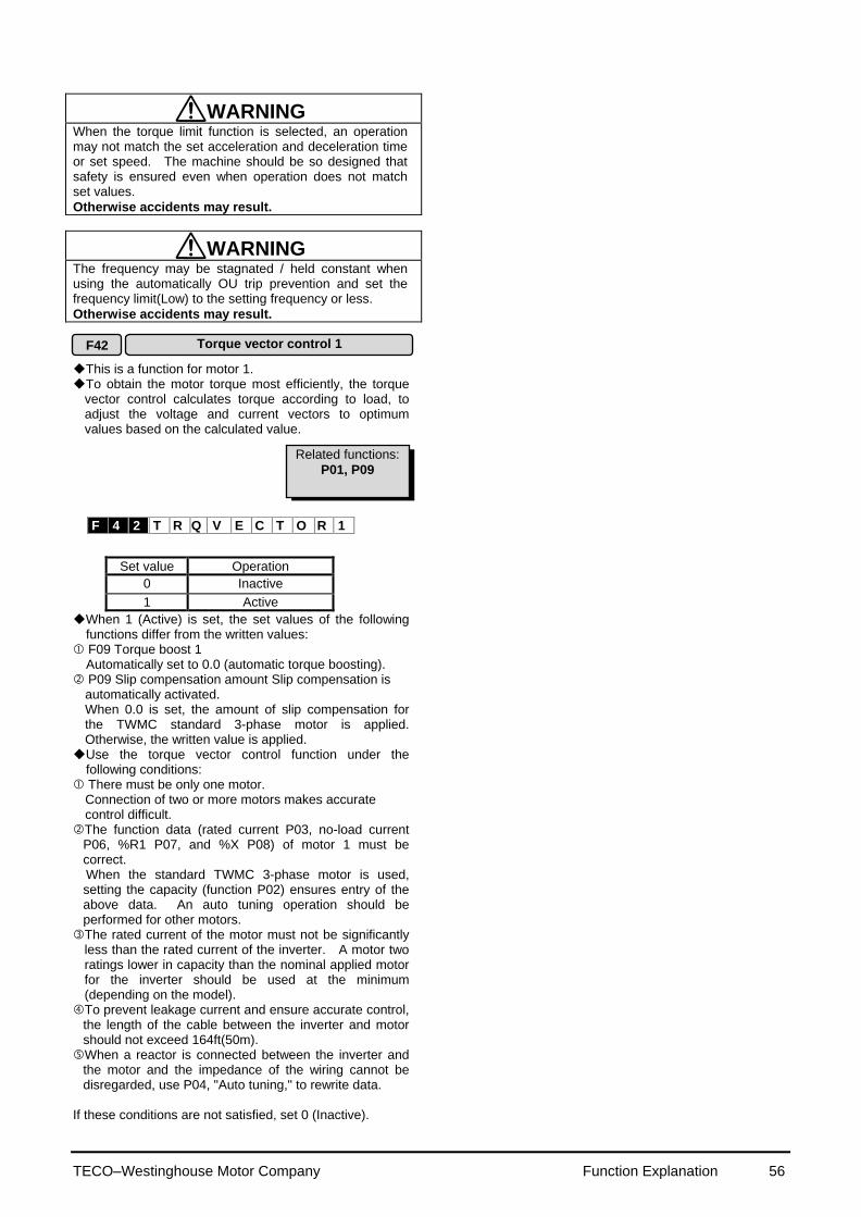
TECO–Westinghouse Motor Company Function Explanation 56
WARNING When the torque limit function is selected, an operation may not match the set acceleration and deceleration time or set speed. The machine should be so designed that safety is ensured even when operation does not match set values.
Otherwise accidents may result.
WARNING The frequency may be stagnated / held constant when using the automatically OU trip prevention and set the frequency limit(Low) to the setting frequency or less.
Otherwise accidents may result.
This is a function for motor 1. To obtain the motor torque most efficiently, the torque
vector control calculates torque according to load, to adjust the voltage and current vectors to optimum values based on the calculated value.
Set value Operation
0 Inactive
1 Active
When 1 (Active) is set, the set values of the following functions differ from the written values:
F09 Torque boost 1 Automatically set to 0.0 (automatic torque boosting). P09 Slip compensation amount Slip compensation is
automatically activated. When 0.0 is set, the amount of slip compensation for the TWMC standard 3-phase motor is applied. Otherwise, the written value is applied.
Use the torque vector control function under the following conditions:
There must be only one motor. Connection of two or more motors makes accurate control difficult.
The function data (rated current P03, no-load current P06, %R1 P07, and %X P08) of motor 1 must be correct.
When the standard TWMC 3-phase motor is used, setting the capacity (function P02) ensures entry of the above data. An auto tuning operation should be performed for other motors. The rated current of the motor must not be significantly
less than the rated current of the inverter. A motor two ratings lower in capacity than the nominal applied motor for the inverter should be used at the minimum (depending on the model). To prevent leakage current and ensure accurate control,
the length of the cable between the inverter and motor should not exceed 164ft(50m). When a reactor is connected between the inverter and
the motor and the impedance of the wiring cannot be disregarded, use P04, "Auto tuning," to rewrite data.
If these conditions are not satisfied, set 0 (Inactive).
F 4 2 T R Q V E C T O R 1
Related functions:
P01, P09
F42 Torque vector control 1
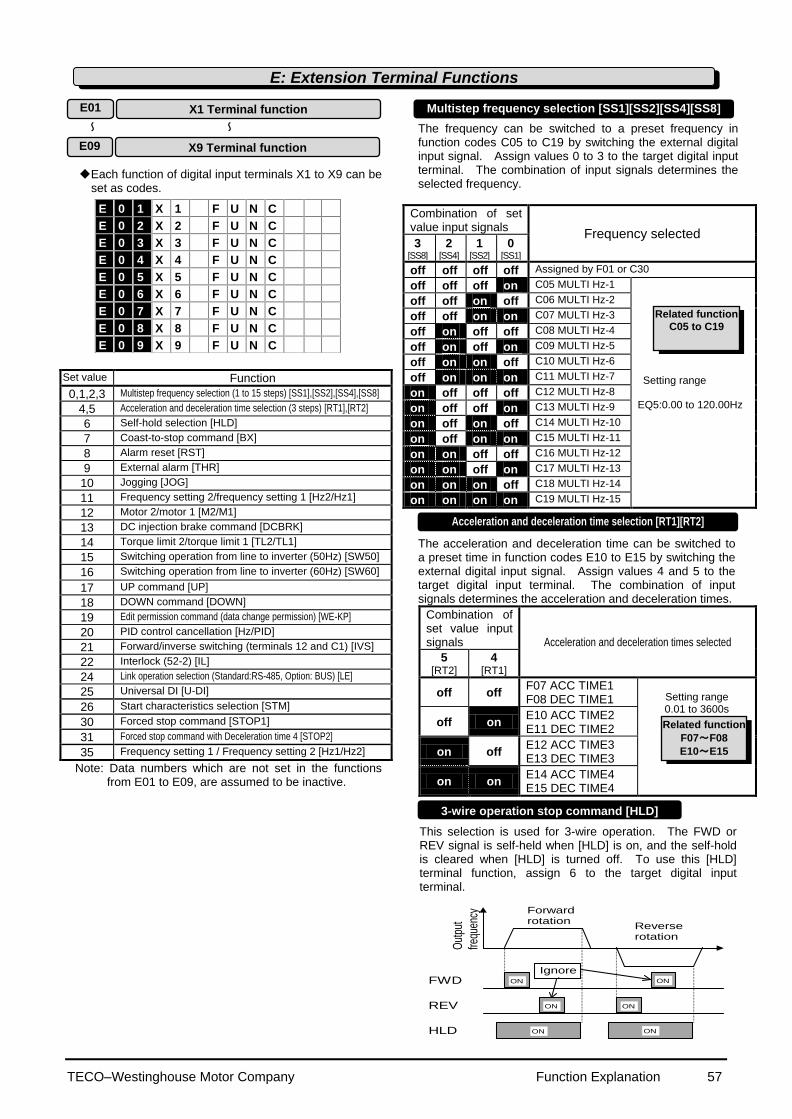
TECO–Westinghouse Motor Company Function Explanation 57
ON ON
ON ON
ON ON
FWD
REV
HLD
Out
put
frequ
ency
Forward rotation
Reverse rotation
Ignored.
Each function of digital input terminals X1 to X9 can be
set as codes.
Set value Function
0,1,2,3 Multistep frequency selection (1 to 15 steps) [SS1],[SS2],[SS4],[SS8]
4,5 Acceleration and deceleration time selection (3 steps) [RT1],[RT2]
6 Self-hold selection [HLD]
7 Coast-to-stop command [BX]
8 Alarm reset [RST]
9 External alarm [THR]
10 Jogging [JOG]
11 Frequency setting 2/frequency setting 1 [Hz2/Hz1]
12 Motor 2/motor 1 [M2/M1]
13 DC injection brake command [DCBRK]
14 Torque limit 2/torque limit 1 [TL2/TL1]
15 Switching operation from line to inverter (50Hz) [SW50]
16 Switching operation from line to inverter (60Hz) [SW60]
17 UP command [UP]
18 DOWN command [DOWN]
19 Edit permission command (data change permission) [WE-KP]
20 PID control cancellation [Hz/PID]
21 Forward/inverse switching (terminals 12 and C1) [IVS]
22 Interlock (52-2) [IL]
24 Link operation selection (Standard:RS-485, Option: BUS) [LE]
25 Universal DI [U-DI]
26 Start characteristics selection [STM]
30 Forced stop command [STOP1]
31 Forced stop command with Deceleration time 4 [STOP2]
35 Frequency setting 1 / Frequency setting 2 [Hz1/Hz2]
Note: Data numbers which are not set in the functions from E01 to E09, are assumed to be inactive.
The frequency can be switched to a preset frequency in function codes C05 to C19 by switching the external digital input signal. Assign values 0 to 3 to the target digital input terminal. The combination of input signals determines the selected frequency.
Combination of set value input signals
Frequency selected 3
[SS8] 2
[SS4] 1
[SS2] 0
[SS1]
off off off off Assigned by F01 or C30
off off off on C05 MULTI Hz-1
Setting range EQ5:0.00 to 120.00Hz
off off on off C06 MULTI Hz-2
off off on on C07 MULTI Hz-3
off on off off C08 MULTI Hz-4
off on off on C09 MULTI Hz-5
off on on off C10 MULTI Hz-6
off on on on C11 MULTI Hz-7
on off off off C12 MULTI Hz-8
on off off on C13 MULTI Hz-9
on off on off C14 MULTI Hz-10
on off on on C15 MULTI Hz-11
on on off off C16 MULTI Hz-12
on on off on C17 MULTI Hz-13
on on on off C18 MULTI Hz-14
on on on on C19 MULTI Hz-15
The acceleration and deceleration time can be switched to a preset time in function codes E10 to E15 by switching the external digital input signal. Assign values 4 and 5 to the target digital input terminal. The combination of input signals determines the acceleration and deceleration times.
Combination of set value input signals Acceleration and deceleration times selected
5 [RT2]
4 [RT1]
off off F07 ACC TIME1 F08 DEC TIME1
Setting range 0.01 to 3600s
off on E10 ACC TIME2 E11 DEC TIME2
on off E12 ACC TIME3 E13 DEC TIME3
on on E14 ACC TIME4 E15 DEC TIME4
This selection is used for 3-wire operation. The FWD or REV signal is self-held when [HLD] is on, and the self-hold is cleared when [HLD] is turned off. To use this [HLD] terminal function, assign 6 to the target digital input terminal.
E 0 1 X 1 F U N C
E 0 2 X 2 F U N C
E 0 3 X 3 F U N C
E 0 4 X 4 F U N C
E 0 5 X 5 F U N C
E 0 6 X 6 F U N C
E 0 7 X 7 F U N C
E 0 8 X 8 F U N C
E 0 9 X 9 F U N C
E: Extension Terminal Functions
E01 X1 Terminal function
E09 X9 Terminal function
~ ~
Multistep frequency selection [SS1][SS2][SS4][SS8]
Acceleration and deceleration time selection [RT1][RT2]
Related function
C05 to C19
Related function
F07~F08
E10~E15
3-wire operation stop command [HLD]
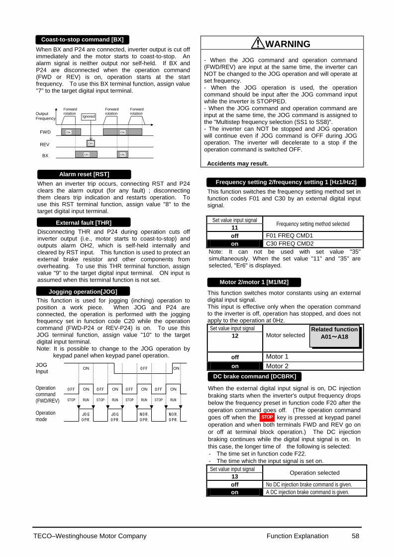
TECO–Westinghouse Motor Company Function Explanation 58
When BX and P24 are connected, inverter output is cut off immediately and the motor starts to coast-to-stop. An alarm signal is neither output nor self-held. If BX and P24 are disconnected when the operation command (FWD or REV) is on, operation starts at the start frequency. To use this BX terminal function, assign value "7" to the target digital input terminal.
When an inverter trip occurs, connecting RST and P24 clears the alarm output (for any fault) ; disconnecting them clears trip indication and restarts operation. To use this RST terminal function, assign value "8" to the target digital input terminal. Disconnecting THR and P24 during operation cuts off inverter output (i.e., motor starts to coast-to-stop) and outputs alarm OH2, which is self-held internally and cleared by RST input. This function is used to protect an external brake resistor and other components from overheating. To use this THR terminal function, assign value "9" to the target digital input terminal. ON input is assumed when this terminal function is not set. This function is used for jogging (inching) operation to position a work piece. When JOG and P24 are connected, the operation is performed with the jogging frequency set in function code C20 while the operation command (FWD-P24 or REV-P24) is on. To use this JOG terminal function, assign value "10" to the target digital input terminal. Note: It is possible to change to the JOG operation by
keypad panel when keypad panel operation.
WARNING - When the JOG command and operation command (FWD/REV) are input at the same time, the inverter can NOT be changed to the JOG operation and will operate at set frequency. - When the JOG operation is used, the operation command should be input after the JOG command input while the inverter is STOPPED. - When the JOG command and operation command are input at the same time, the JOG command is assigned to the "Multistep frequency selection (SS1 to SS8)". - The inverter can NOT be stopped and JOG operation will continue even if JOG command is OFF during JOG operation. The inverter will decelerate to a stop if the operation command is switched OFF.
Accidents may result.
This function switches the frequency setting method set in function codes F01 and C30 by an external digital input signal.
Set value input signal Frequency setting method selected
11
off F01 FREQ CMD1
on C30 FREQ CMD2
Note: It can not be used with set value "35" simultaneously. When the set value "11" and "35" are selected, "Er6" is displayed. This function switches motor constants using an external digital input signal. This input is effective only when the operation command to the inverter is off, operation has stopped, and does not apply to the operation at 0Hz.
Set value input signal Motor selected 12
off Motor 1
on Motor 2
When the external digital input signal is on, DC injection
braking starts when the inverter's output frequency drops
below the frequency preset in function code F20 after the
operation command goes off. (The operation command
goes off when the key is pressed at keypad panel
operation and when both terminals FWD and REV go on
or off at terminal block operation.) The DC injection
braking continues while the digital input signal is on. In
this case, the longer time of the following is selected:
- The time set in function code F22.
- The time which the input signal is set on.
Set value input signal Operation selected
13
off No DC injection brake command is given.
on A DC injection brake command is given.
Forward rotation
ON
ON ON
ON ON FWD
REV
BX
Output Frequency
Ignored
Forward rotation
Forward rotation
ON Operation command (FWD/REV)
Operation mode
JOG Input
O FF
JO G
O PR.
O FF
STOP RUN STOP
ON
RUN
JO G
O PR.
ON O FF
O FF
STOP
ON
RUN
O FF
STOP
NO R.
O PR.
NO R.
O PR.
ON
RUN
ON
Coast-to-stop command [BX]
External fault [THR]
Jogging operation[JOG]
Motor 2/motor 1 [M1/M2]
DC brake command [DCBRK]
Related function
A01~A18
Alarm reset [RST] Frequency setting 2/frequency setting 1 [Hz1/Hz2]
STOP
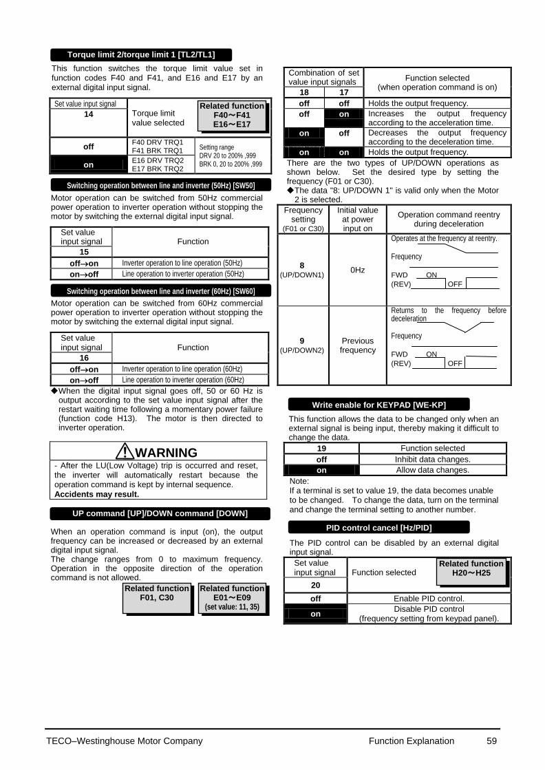
TECO–Westinghouse Motor Company Function Explanation 59
This function switches the torque limit value set in function codes F40 and F41, and E16 and E17 by an external digital input signal.
Set value input signal Torque limit value selected
14
off F40 DRV TRQ1 F41 BRK TRQ1
Setting range DRV 20 to 200% ,999 BRK 0, 20 to 200% ,999 on
E16 DRV TRQ2 E17 BRK TRQ2
Motor operation can be switched from 50Hz commercial power operation to inverter operation without stopping the motor by switching the external digital input signal.
Set value input signal
Function
15
offon Inverter operation to line operation (50Hz)
onoff Line operation to inverter operation (50Hz)
Motor operation can be switched from 60Hz commercial power operation to inverter operation without stopping the motor by switching the external digital input signal.
Set value input signal
Function
16
offon Inverter operation to line operation (60Hz)
onoff Line operation to inverter operation (60Hz)
When the digital input signal goes off, 50 or 60 Hz is output according to the set value input signal after the restart waiting time following a momentary power failure (function code H13). The motor is then directed to inverter operation.
WARNING - After the LU(Low Voltage) trip is occurred and reset, the inverter will automatically restart because the operation command is kept by internal sequence.
Accidents may result.
When an operation command is input (on), the output frequency can be increased or decreased by an external digital input signal. The change ranges from 0 to maximum frequency. Operation in the opposite direction of the operation command is not allowed.
Combination of set value input signals
Function selected (when operation command is on)
18 17
off off Holds the output frequency.
off on Increases the output frequency according to the acceleration time.
on off Decreases the output frequency according to the deceleration time.
on on Holds the output frequency.
There are the two types of UP/DOWN operations as shown below. Set the desired type by setting the frequency (F01 or C30). The data "8: UP/DOWN 1" is valid only when the Motor
2 is selected.
Frequency setting
(F01 or C30)
Initial value at power input on
Operation command reentry during deceleration
8 (UP/DOWN1)
0Hz
Operates at the frequency at reentry. Frequency
FWD ON
(REV) OFF
9 (UP/DOWN2)
Previous frequency
Returns to the frequency before deceleration
Frequency
FWD ON
(REV) OFF
This function allows the data to be changed only when an external signal is being input, thereby making it difficult to change the data.
19 Function selected
off Inhibit data changes.
on Allow data changes.
Note: If a terminal is set to value 19, the data becomes unable to be changed. To change the data, turn on the terminal and change the terminal setting to another number.
The PID control can be disabled by an external digital input signal.
Set value input signal
Function selected
20
off Enable PID control.
on Disable PID control
(frequency setting from keypad panel).
UP command [UP]/DOWN command [DOWN]
Write enable for KEYPAD [WE-KP]
PID control cancel [Hz/PID]
Related function H20~H25
Switching operation between line and inverter (50Hz) [SW50]
Switching operation between line and inverter (60Hz) [SW60]
Torque limit 2/torque limit 1 [TL2/TL1]
Related function F40~F41 E16~E17
Write enable for KEYPAD [WE-KP]
Related function E01~E09
(set value: 11, 35)
Related function F01, C30

TECO–Westinghouse Motor Company Function Explanation 60
The analog input (terminals 12 and C1) can be switched between forward and inverse operations by an external digital input signal.
Set value input signal
Function selected
21
off Forward operation when forward operation is set and vice versa
on Inverse operation when forward operation is set and vice versa
This function is invalid when the PID control is selected(H20: 1 or 2).
When a contactor is installed on the output side of the inverter, the contactor opens at the time of a momentary power failure, which hinders the reduction of the DC circuit voltage and may prevent the detection of a power failure and the correct restart operation when power is recovered. The restart operation at momentary power failure can be performed effectively with power failure information provided by an external digital input signal.
Set value input signal
Function selected
22
off No momentary power failure detection operation by digital input
on Momentary power failure detection operation by digital input
Frequency and operation commands from the link can be enabled or disabled by switching the external digital input signal. Select the command source in H30, "Link function." Assign value "24" to the target digital input terminal and enable or disable commands in this input signal state.
Set value input signal
Function selected
24
off Link command disabled.
on Link command enabled.
Assigning value "25" to a digital input terminal renders the terminal a universal DI terminal. The ON/OFF state of signal input to this terminal can be checked through the RS-485 and BUS option. This input terminal is only used to check for an incoming input signal through communication and does not affect inverter operation.
The start characteristics function (pick-up mode) in function code H09 can be enabled or disabled by switching the external digital input signal. Assign value "26" to the target digital input terminal and enable or disable the function in this input signal state.
Set value input signal
Function selected
26
off Start characteristic function disabled
on Start characteristic function enabled
Normally this terminal should be “ON”, when this terminal goes off during motor running, the motor decelerates to stop, and outputs alarm “Er6 “. When the inverter is stop by STOP1/STOP2 signal, the signal should be kept on 4ms or longer. In case of terminal [STOP2], the deceleration time is determined by E15( DEC TIME4). This function is prioritized under any operation (Terminal. Keypad, Communication...operation). However when the torque limiter/regeneration avoidance at deceleration is selected, the time which is set by deceleration time may be longer.
Inverse mode changeover [IVS]
Interlock signal (52-2) [IL]
Related function F01, C30
Universal DI (U-DI)
Pick up start mode [STM]
Related function H09
Related function H30
Synchronization command ( Option ) [SYC]
ON
Er6
ON
ON ON FWD or REV
[STOP1] or [STOP2]
Alarm
Output Frequency
In case of [STOP2], time is fixed by E15 (EDC TIME4)
Forced stop command with Deceleration [STOP1]
Forced stop command with Deceleration time 4 [STOP2]
Related function F14

TECO–Westinghouse Motor Company Function Explanation 61
Related functions
E01 to E09
(Set values:14)
Related functions
U01
U60
Related functions
E01~E09
(Set value: 14)
This function switches the frequency setting method
set in function codes F01 and C30 by an external digital input signal. This is the reverse-logic of setting value "11"(Frequency setting 2/Frequency setting 1 [Hz2/Hz1]).
Set value input signal Frequency setting method selected
35
off C30 FREQ CMD2
on F01 FREQ CMD1
Note: It can not be used with set value "11" simultaneously. When the set value "11" and "35" are selected, "Er6" is displayed.
Digital input
Setting at factory shipment
Set value
Description
Terminal X1 0 Multistep frequency selection [SS1]
Terminal X2 1 Multistep frequency selection [SS2]
Terminal X3 2 Multistep frequency selection [SS4]
Terminal X4 3 Multistep frequency selection [SS8]
Terminal X5 4 Acceleration and deceleration selection [RT1]
Terminal X6 5 Acceleration and deceleration selection [RT2]
Terminal X7 6 Self-hold selection [HLD]
Terminal X8 7 Coast-to-stop command [BX]
Terminal X9 8 Alarm reset [RST]
Acceleration time 1 (F07) and deceleration time 1 (F08)
as well as three other types of acceleration and deceleration time can be selected.
The operation and setting ranges are the same as those of acceleration time 1 and deceleration time 1. See explanations for F07 and F08.
For switching acceleration and deceleration times, select any two terminals from terminal X1 (function selection) in E01 to terminal X9 (function selection) in E09 as switching signal input terminals. Set "4" (acceleration and deceleration time 1) and "5" (acceleration and deceleration time 2) to the selected terminals and input a signal to each terminal to switch acceleration and deceleration times. Switching is possible during acceleration, deceleration, or constant-speed operation.
Example: When 4 and 5 are set to terminals X2 and X3:
ONTime
ON
ON
FWD
(REV)
X2
X3
P24
Operation
Output
frequency
Maximum
frequency
Accel
time
1
Decel
time
1
Accel
time
2
Decel
time
2
Accel
time
3
Decel
time
3
Accel
time
4
Decel
time
4
This function is used to switch the torque limit level set
in F40 and F41 by an external control signal. Input an external signal by selecting any of the control input terminals (X1 to X9) as torque limit 2/torque limit 1 (value 14) in E01 to E09.
The motor tuning (P04 / A13) should be set to "2" for this function is valid.
Maximum compensation frequency during braking torque limit is set by U01.
The operation mode is set by U60 when the setting
value is "0%: Regeneration avoidance at deceleration". The detail is referred to the U01, U60.
E 1 6 D R V T R Q 2
E 1 7 B R K T R Q 2
E16 Torque limiter 2 (driving)
Torque limiter 2 (braking) E17
Settings when shipped from the factory
E10 Acceleration time 2
E11 Deceleration time 2
E12 Acceleration time 3
E13 Deceleration time 3
E14 Acceleration time 4
E15 Deceleration time 4
E 1 0 A C C T I M E 2
E 1 1 D E C T I M E 2
E 1 2 A C C T I M E 3
E 1 3 D E C T I M E 3
E 1 4 A C C T I M E 4
E 1 5 D E C T I M E 4
Frequency setting 1 / Frequency setting 2 [Hz1/Hz2]
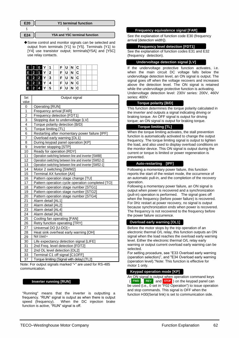
TECO–Westinghouse Motor Company Function Explanation 62
Some control and monitor signals can be selected and output from terminals [Y1] to [Y5]. Terminals [Y1] to [Y4] use transistor output; terminals[Y5A] and [Y5C] use relay contacts.
Set value
Output signal
0 Operating [RUN]
1 Frequency arrival [FAR]
2 Frequency detection [FDT1]
3 Stopping due to undervoltage [LV]
4 Torque polarity detection [B/D]
5 Torque limiting [TL]
6 Restarting after momentary power failure [IPF]
7 Overload early warning [OL1]
8 During keypad panel operation [KP]
9 Inverter stopping [STP]
10 Ready for operation [RDY]
11 Operation switching between line and inverter [SW88]
12 Operation switching between line and inverter [SW52-2]
13 Operation switching between line and inverter [SW52-1]
14 Motor 2 switching [SWM2]
15 Terminal AX function [AX]
16 Pattern operation stage change [TU]
17 Pattern operation cycle operation completed [TO]
18 Pattern operation stage number [STG1]
19 Pattern operation stage number [STG2]
20 Pattern operation stage number [STG4]
21 Alarm detail [AL1]
22 Alarm detail [AL2]
23 Alarm detail [AL4]
24 Alarm detail [AL8]
25 Cooling fan operating [FAN]
26 Retry function operating [TRY]
27 Universal DO [U-DO]
28 Heat sink overheat early warning [OH]
29 Not Used
30 Life expectancy detection signal [LIFE]
31 2nd Freq. level detection [FDT2]
32 2nd OL level detection [OL2]
33 Terminal C1 off signal [C1OFF]
37 Torque limiting (Signal with delay) [TL2]
Note: For output signals marked "" are used for RS-485 communication.
"Running" means that the inverter is outputting a frequency. “RUN” signal is output as when there is output speed (frequency). When the DC injection brake function is active, “RUN” signal is off.
See the explanation of function code E30 (frequency arrival [detection width]). See the explanation of function codes E31 and E32 (frequency detection). If the undervoltage protective function activates, i.e. when the main circuit DC voltage falls below the undervoltage detection level, an ON signal is output. The signal goes off when the voltage recovers and increases above the detection level. The ON signal is retained while the undervoltage protective function is activating. Undervoltage detection level: 230V series: 200V, 460V series: 400V. This function determines the torque polarity calculated in the inverter and outputs a signal indicating driving or braking torque. An OFF signal is output for driving torque; an ON signal is output for braking torque. When the torque limiting activates, the stall prevention function is automatically activated to change the output frequency. The torque limiting signal is output to lighten the load, and also used to display overload conditions on the monitor device. This ON signal is output during the current or torque is limited or power regeneration is prevented. Following a momentary power failure, this function reports the start of the restart mode, the occurrence of an automatic pull-in, and the completion of the recovery operation. Following a momentary power failure, an ON signal is output when power is recovered and a synchronization (pull-in) operation is performed. The signal goes off when the frequency (before power failure) is recovered. For 0Hz restart at power recovery, no signal is output because synchronization ends when power is recovered. The frequency is not recovered to the frequency before the power failure occurrence.
Before the motor stops by the trip operation of an electronic thermal O/L relay, this function outputs an ON signal when the load reaches the overload early warning level. Either the electronic thermal O/L relay early warning or output current overload early warning can be selected. For setting procedure, see “E33 Overload early warning (operation selection)”, and "E34 Overload early warning (operation level)."Note: This function is effective for motor 1 only.
An ON signal is output when operation command keys
( , and ) on the keypad panel can
be used (i.e., 0 set in "F02 Operation") to issue operation
and stop commands. This signal is OFF when the
function H30(Serial link) is set to communication side.
E 2 0 Y 1 F U N C
E 2 1 Y 2 F U N C
E 2 2 Y 3 F U N C
E 2 3 Y 4 F U N C
E 2 4 Y 5 F U N C
Inverter running [RUN]
Undervoltage detection signal [LV]
Keypad operation mode [KP]
運転中[RUN]
Frequency equivalence signal [FAR]
Frequency level detection [FDT1]
Torque polarity [B/D]
Torque limiting [TL]
Auto-restarting [IPF]
Overload early warning [OL1]
E20 Y1 terminal function
E24 Y5A and Y5C terminal function
~ ~
FWD STOP REV

TECO–Westinghouse Motor Company Function Explanation 63
This function outputs an inverted signal to Running (RUN) to indicate zero speed. An ON signal is output when the DC injection brake function is operating. This function outputs an ON signal when the inverter is ready to operate. The inverter is ready to operate when the main circuit and control circuit power is established and the inverter protective function is not activating. About one second is required from power-on to ready for operation in normal condition. To perform switching operation between the line and the inverter, the sequence prepared in the inverter can be used to select and output signals for opening and closing the magnetic contactors connected to the inverter. As the operation is complex, refer to technical documentation for the EQ5 series when using this function. As the sequence will operate automatically when SW88 or SW52-2 is selected, do not select when not using the sequence. When a signal for switching to motor 2 is input from the terminal selected by terminals [X1] to [X9], this function selects and outputs the signal for switching the magnetic contactor for the motor. As this switching signal is not output during running including when the DC injection braking function is operating, a signal must be re-input after output stops. When an operation (forward or reverse) command is entered, this function outputs an ON signal. When a stop command is entered, the signal goes off after inverter output stops. When a coast-to-stop command is entered and the inverter protective function operates, the signal goes off immediately. When the pattern operation stage changes, this function outputs a one-shot (100ms) ON signal to report a stage change. When the seven stages of a pattern operation are completed, this function outputs a one-shot (100 ms) ON signal to report the completion of all stages. During pattern operation, this function reports the stage (operation process) being operated.
Pattern operation stage No.
Output terminal
STG1 STG2 STG4
Stage 1 on off off
Stage 2 off on off
Stage 3 on on off
Stage 4 off off on
Stage 5 on off on
Stage 6 off on on
Stage 7 on on on
When pattern operation is not activated (i.e., no stage is selected), the terminals do not output a signal.
This function reports the operating status of the inverter protective function.
Alarm detail (inverter protective function)
Output terminal
AL1 AL2 AL4 AL8 Overcurrent, ground fault, fuse blown on off off off Overvoltage off on off off Undervoltage shortage, input phase failure on on off off Motors 1 and 2 overload off off on off Inverter overload on off on off Heat sink overheating, inverter inside overheating off on on off External alarm input, braking resistor overheating on on on off Memory error, CPU error off off off on Keypad panel communication error, option communication error on off off on Option error off on off on Output wiring error off off on on RS-485 communication error on off on on Not Used EQ5 off on on on
In normal operation terminals do not output a signal. When used with "H06 Cooling fan ON/OFF control," this function outputs a signal while the cooling fan is operating. When a value of 1 or larger is set to "H04 Retry operating," the signal is output while retry operation is activating when the inverter protective function is activated. Assigning value "27" to a transistor output terminal renders the terminal a universal DO terminal. This function enables ON/OFF through the RS-485 and BUS option. This function serves only to turn on and off the transistor output through communication and is not related to inverter operation.
This function outputs a early warning signal when heat
sink temperature is (overheat detection level - 10) or
higher. When either of data for the Life expectancy judgment
of the function code:U09 to U11 reaches at the Life expectancy judgment level, the ON signal is output. However, the inverter does not do alarm. Moreover, the alarm output for any fault (30A, 30B, 30C ) does not operate.
Function code
Parts of Life expectancy judgment
Life expectancy judgment level
U09 Capacitor in main circuit 85% or less of the initial value
U10 Electrolytic capacitor on PCB 61,000 hours
U11 Cooling fan 25,000 hours
U59 DC fan broken for stir internal unit up
[40HP/CT, 50HP/VT or more is
annunciated.]
DC fan is broken
Inverter stopping [STOP]
Ready output [RDY]
Line/Inv changeover [SW88] [SW52-2] [SW52-1]
Auto-resetting [TRY]
Cycle completion signal for pattern operation [TO]
Motor 2 /Motor 1 [SWM2]
Auxiliary terminal [AX]
Time-up signal for pattern operation [TU]
Stage No. indication for pattern operation [STG1] [STG2] [STG4]
Alarm indication [AL1] [AL2] [AL4] [AL8]
Overheat early warning [OH]
Fan operation signal [FAN]
Universal DO [U-DO]
Life expectancy detection signal [LIFE]
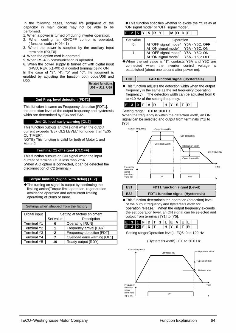
TECO–Westinghouse Motor Company Function Explanation 64
Related functions
U08~U11, U59
In the following cases, normal life judgment of the capacitor in main circuit may not be able to be performed. 1. When a power is turned off during inverter operation. 2. When cooling fan ON/OFF control is operated.
( function code : H 06= 1) 3. When the power is supplied by the auxiliary input
terminals (R0,T0). 4. When the option card is operated . 5. When RS-485 communication is operated . 6. When the power supply is turned off with digital input
(FWD, REV, X1-X9) of a control terminal being ON. In the case of "3", "4", "5" and "6", life judgment is enabled by adjusting the function both code:U08 and U09.
This function is same as Frequency detection [FDT1], the detection level of the output frequency and hysteresis width are determined by E36 and E32. This function outputs an ON signal when the output current exceeds “E37 OL2 LEVEL” for longer than “E35 OL TIMER”. NOTE) This function is valid for both of Motor 1 and Motor 2. This function outputs an ON signal when the input current of terminal C1 is less than 2mA. (When AIO option is connected, it can be detected the disconnection of C2 terminal.) The turning on signal is output by continuing the
limiting action(Torque limit operation, regeneration avoidance operation and overcurrent limiting operation) of 20ms or more.
Digital input Setting at factory shipment
Set value Description
Terminal Y1 0 Operating [RUN]
Terminal Y2 1 Frequency arrival [FAR]
Terminal Y3 2 Frequency detection [FDT]
Terminal Y4 7 Overload early warning [OL1]
Terminal Y5 10 Ready output [RDY]
This function specifies whether to excite the Y5 relay at “ON signal mode” or “OFF signal mode”.
Set value Operation
0 At “OFF signal mode” Y5A - Y5C: OFF At “ON signal mode” Y5A - Y5C: ON
1 At “OFF signal mode” Y5A - Y5C: ON At “ON signal mode” Y5A - Y5C: OFF
When the set value is "1", contacts Y5A and Y5C are connected when the inverter control voltage is established (about one second after power on). This function adjusts the detection width when the output
frequency is the same as the set frequency (operating frequency). The detection width can be adjusted from 0
to 10 Hz of the setting frequency.
Setting range: 0.0 to 10.0 Hz When the frequency is within the detection width, an ON signal can be selected and output from terminals [Y1] to [Y5].
Output frequency
Frequency
detection
signal
(terminals
Y1 to Y5)
+Detection width
-Detection width
Set frequency
+Detection width
-Detection width
Set frequency
Time
ONON
This function determines the operation (detection) level
of the output frequency and hysteresis width for operation release. When the output frequency exceeds the set operation level, an ON signal can be selected and output from terminals [Y1] to [Y5].
Setting range(Operation level) : EQ5: 0 to 120 Hz
(Hysteresis width) : 0.0 to 30.0 Hz
Output frequency
Frequency
detection
signal
(terminals
Y1 to Y5)
Hysteresis width
Operation level
Release level
Time
ON
Set frequency
E30 FAR function signal (Hysteresis)
E 3 0 F A R H Y S T R
E32 FDT1 function signal (Hysteresis)
E31 FDT1 function signal (Level)
Settings when shipped from the factory
2nd Freq. level detection [FDT2]
2nd OL level early warning [OL2]
Terminal C1 off signal [C1OFF]
E 3 1 F D T 1 L E V E L
E 3 2 F D T H Y S T R
E25 Y5 Ry operation mode
E 2 5 Y 5 R Y M O D E
Torque limiting (Signal with delay) [TL2]

TECO–Westinghouse Motor Company Function Explanation 65
Select one of the following two types of overload early warning: early warning by electronic thermal O/L relay function or early warning by output current.
Set value 0: Electronic thermal O/L relay 1: Output current
Set value
Function Description
0 Electronic thermal O/L relay
Overload early warning by electronic thermal O/L relay (having inverse-time characteristics) to output current. The operation selection and thermal time constant for the inverse-time characteristics are the same as those of the electronic thermal O/L relay for motor protection (F10 and F12).
1 Output current
An overload early warning is issued when output current exceeds the set current value for the set time. The figure of OL2(E37) is referred.
This function cannot be used when Motor 2 is selected. This function determines the operation level of the
electronic thermal O/L relay or output current.
Setting range EQ5:Inverter rated output current x (5 to 150%) The operation release level is 90% of the set value.
This function cannot be used when Motor 2 is selected.
This function is used when 1 (output current) is set to "E33 Overload early warning (operation selection)." Setting range: 0.1 to 60.0 seconds
Set the time from when the operation level is attained until the overload early warning function is activated.
This function determines the operation (detection) level
of output frequency for “2nd Freq. level detection [FDT2]”. The hysteresis width for operation release is set by the function E32: FDT1 function signal (Hysteresis). Setting range(Operation level) : EQ5: 0 to 120 Hz
This function determines the operation level of the output current for “2nd OL level detection [OL2]”.
Setting range EQ5: Inverter rated output current x (5 to 150%)
The operation release level is 90% of the set value.
ON
E37 OL2 LEVEL
E35 OL TIMER
[OL2]
Output current
OL2 LEVEL x 90% (E34 OL1 LEVEL) (OL1 LEVEL x 90%)
These coefficients are conversion coefficients which are used to determine the load and line speed and the target value and feedback amount (process amount) of the PID controller displayed on the LED monitor.
Setting range Display coefficient A:-999.00 to 0.00 to +999.00 Display coefficient B:-999.00 to 0.00 to +999.00
Load and line speed Use the display coefficient A.
Displayed value = output frequency x (0.01 to 200.00)
Although the setting range is ±999.00, the effective
value range of display data is 0.01 to 200.00. Therefore, values smaller or larger than this range are limited to a minimum value of 0.01 or a maximum value of 200.00.
Target value and feedback amount of PID controller Set the maximum value of display data in E40, "Display coefficient A," and the minimum value in E41, "Display coefficient B." Displayed value = (target value or feedback amount) x (display coefficient A - B)+B
E 3 3 O L W A R N I N G
E 3 4 O L 1 L E V E L
E 3 5 O L 1 T I M E R
E 4 0 C O E F A
E 4 1 C O E F B
E34 OL function signal (Level)
E35 OL function signal (Timer)
Displayed value
A
Target value or feedback amount
B
0% 100%
E40 Display coefficient A
E41 Display coefficient B
E33 OL function signal (mode select) selection
E36 FDT2 function (Level)
E 3 6 F D T 2 L E V E L
E37 OL2 function (Level)
E 3 7 O L 2 L E V E L
E40 Display coefficient A
E41 Display coefficient B
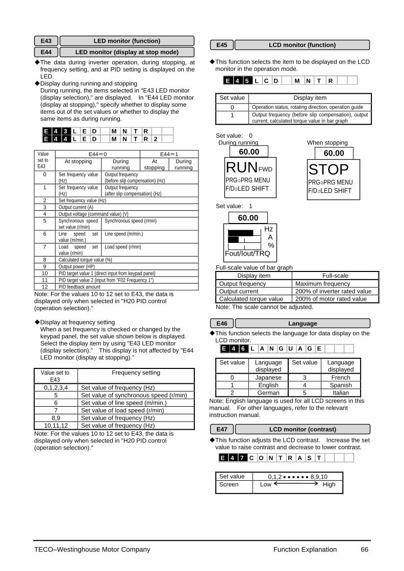
TECO–Westinghouse Motor Company Function Explanation 66
E 4 6 L A N G U A G E
The data during inverter operation, during stopping, at frequency setting, and at PID setting is displayed on the LED.
Display during running and stopping During running, the items selected in "E43 LED monitor (display selection)," are displayed. In "E44 LED monitor (display at stopping)," specify whether to display some items out of the set values or whether to display the same items as during running.
Value set to E43
E44=0 E44=1
At stopping During running
At stopping
During running
0 Set frequency value (Hz)
Output frequency (before slip compensation) (Hz)
1 Set frequency value (Hz)
Output frequency (after slip compensation) (Hz)
2 Set frequency value (Hz)
3 Output current (A)
4 Output voltage (command value) (V)
5 Synchronous speed set value (r/min)
Synchronous speed (r/min)
6 Line speed set value (m/min.)
Line speed (m/min.)
7 Load speed set value (r/min)
Load speed (r/min)
8 Calculated torque value (%)
9 Output power (HP)
10 PID target value 1 (direct input from keypad panel)
11 PID target value 2 (input from "F02 Frequency 1")
12 PID feedback amount
Note: For the values 10 to 12 set to E43, the data is displayed only when selected in "H20 PID control (operation selection)." Display at frequency setting
When a set frequency is checked or changed by the keypad panel, the set value shown below is displayed. Select the display item by using "E43 LED monitor (display selection)." This display is not affected by "E44 LED monitor (display at stopping)."
Value set to E43
Frequency setting
0,1,2,3,4 Set value of frequency (Hz)
5 Set value of synchronous speed (r/min)
6 Set value of line speed (m/min.)
7 Set value of load speed (r/min)
8,9 Set value of frequency (Hz)
10,11,12 Set value of frequency (Hz)
Note: For the values 10 to 12 set to E43, the data is displayed only when selected in "H20 PID control (operation selection)."
This function selects the item to be displayed on the LCD monitor in the operation mode.
Set value Display item
0 Operation status, rotating direction, operation guide
1 Output frequency (before slip compensation), output current, calculated torque value in bar graph
Set value: 0
During running When stopping
Set value: 1
Full-scale value of bar graph
Display item Full-scale
Output frequency Maximum frequency
Output current 200% of inverter rated value
Calculated torque value 200% of motor rated value
Note: The scale cannot be adjusted.
This function selects the language for data display on the
LCD monitor.
Set value Language displayed
Set value Language displayed
0 Japanese 3 French
1 English 4 Spanish
2 German 5 Italian
Note: English language is used for all LCD screens in this manual. For other languages, refer to the relevant instruction manual.
This function adjusts the LCD contrast. Increase the set value to raise contrast and decrease to lower contrast.
Set value 0,1,2 8,9,10
Screen Low High
E 4 3 L E D M N T R
E 4 4 L E D M N T R 2
E 4 5 L C D M N T R
Hz A % Fout/Iout/TRQ
60.00
STOP
PRGPRG MENU
F/DLED SHIFT
E45 LCD monitor (function)
60.00
RUN
PRGPRG MENU
F/DLED SHIFT
60.00
E43 LED monitor (function)
E44 LED monitor (display at stop mode)
FWD
E46 Language
E47 LCD monitor (contrast)
E 4 7 C O N T R A S T

TECO–Westinghouse Motor Company Function Explanation 67
This function makes the set frequency jump so that the
inverter's output frequency does not match the mechanical resonance point of the load.
Up to three jump points can be set. This function is ineffective when jump frequencies 1 to 3
are set to 0Hz. A jump does not occur during acceleration or deceleration.
When a jump frequency setting range overlaps another range, both ranges are added to determine the actual jump area.
Setting range: EQ5 : 0 to 120Hz In 1Hz steps (min.)
Setting range 0 to 30Hz
In 1Hz steps (min.) To avoid the resonance of the motor driving frequency to the peculiar vibration frequency of the machine, the jump frequency band can be set to the output frequency up to three point. During accelerating, an internal set frequency is kept
constant by the lower frequency of the jump frequency band when a set frequency enters the jump frequency band. This means that the output frequency is kept constant according to an internal set frequency. When a set frequency exceeds the upper bound of the jump frequency band, an internal set frequency reaches the value of a set frequency. The output frequency accelerates up to a set frequency while passing the jump frequency band according to the acceleration time at this time. During decelerating, it has a relation opposite to accelerating. Refer to figure below.
When two jump frequency bands or more come in succession mutually, the lowest and highest frequency become the lower bound and the upper bound frequency of an actual jump frequency band respectively among them. Refer to upper right figure.
Multistep frequencies 1 to 15 can be switched by turning on and off terminal functions SS1, SS2, SS4, and SS8. (See E01 to E09 for terminal function definitions.)
OFF input is assumed for any undefined terminal of SS1, SS2, SS4, and SS8.
Setting range EQ5: 0.00 to 120.00Hz In 0.01Hz steps (min
Internal set frequency (Hz)
Actual jump width
Jump frequency 2
Jump frequency 1
Set frequency (Hz)
Jump frequency width
C 0 1 J U M P H z 1
C 0 2 J U M P H z 2
C 0 3 J U M P H z 3
C 0 4 J U M P H Y S T R
Internal set frequency (Hz)
Jump frequency 1
Jump frequency width
Jump frequency width
Jump frequency width
Set frequency (Hz)
Jump frequency 2
Jump frequency 3
C 0 5 M U L T I H z - 1
C 0 6 M U L T I H z - 2
C 0 7 M U L T I H z - 3
C 0 8 M U L T I H z - 4
C 0 9 M U L T I H z - 5
C 1 0 M U L T I H z - 6
C 1 1 M U L T I H z - 7
C 1 2 M U L T I H z - 8
C 1 3 M U L T I H z - 9
C 1 4 M U L T I H z 1 0
C 1 5 M U L T I H z 1 1
C 1 6 M U L T I H z 1 2
C 1 7 M U L T I H z 1 3
C 1 8 M U L T I H z 1 4
C 1 9 M U L T I H z 1 5
C:Control Functions of Frequency
C01 Jump frequency 1
Jump frequency 2
C03 Jump frequency 3
C04 Jump frequency (Hysteresis)
C02
Related functions E01 to E09
(Set value:0 to 3)
C05 Multistep frequency 1
C19 Multistep frequency 15
~ ~
Output frequency (Hz)
ON ON ON ON ON ON ON ON
ON
ON ON ON ON
ON ON
ON
C05
FWD-P24
SS1-P24
SS2-P24
SS4-P24
SS8-P24
C06
C07
C08
C09
C10
C11
C12
C13
C14
C15
C16
C17
C18
C19

TECO–Westinghouse Motor Company Function Explanation 68
This function sets the frequency for jogging operation of
motor, which is different from the normal operation.
Setting range EQ5 : 0.00 to 120.00 Hz Starting with the jogging frequency is combined with
jogging select signal input from the keypad panel or control terminal. For details, see the explanations of "E01 Terminal X1" to "E09 Terminal X9." Pattern operation is an automatic operation according to
preset operation time, direction of rotation, acceleration and deceleration time, and frequency. When using this function, set 10 (pattern operation) to "F01 Frequency setting." The following operation patterns can be selected.
Set value Operation pattern
0 Perform a pattern operation cycle, then stop operation.
1 Perform pattern operation repeatedly. Stop operation using a stop command.
2 Perform a pattern operation cycle, then continue operation with the last frequency set.
Time
Set value:0
0
Forward
Output
frequency
Reverse
End of a cycle
0
0
Set value:1
Set value:2
Forward
Output
frequency
Reverse
Forward
Output
frequency
Reverse
Time
Time
End of a cycle
End of a cycle
Seven stages are operated in order (of function codes) according to the values set in "C22 Pattern operation (stage 1)" to "C28 Pattern operation (stage 7)." Each function sets the operation time and the rotating direction for each stage and assigns set values of the acceleration
and deceleration time.
Set or assign item
Value range
Operation time 0.00 to 6000s
Rotation direction
F: Forward (counterclockwise) R: Reverse (clockwise)
Acceleration and deceleration time
1: Acceleration time 1 (F07), deceleration time 1 (F08)
2: Acceleration time 2 (E10), deceleration time 2 (E11)
3: Acceleration time 3 (E12), deceleration time 3 (E13)
4: Acceleration time 4 (E14), deceleration time 4 (E15)
Note: The operation time is represented by the three most significant digits, hence, can be set with only three high-order digits.
Setting example 100 F 3
Acceleration and deceleration time (code): 3
Motor rotating direction: Forward (counterclockwise)
Operation time: 100s
Set the operation time to 0.00 for stages not used, which are skipped in operation. With regard to the set frequency value, the multistep frequency function is assigned as listed in the table below. Set frequencies to "C05 Multistep frequency 1," to "C11 Multistep frequency 7."
Stage No. Operation frequency to be set
Stage 1 Multistep frequency 1 (C05)
Stage 2 Multistep frequency 2 (C06)
Stage 3 Multistep frequency 3 (C07)
Stage 4 Multistep frequency 4 (C08)
Stage 5 Multistep frequency 5 (C09)
Stage 6 Multistep frequency 6 (C10)
Stage 7 Multistep frequency 7 (C11)
C 2 0 J O G H z
C 2 2 S T A G E 1
C 2 3 S T A G E 2
C 2 4 S T A G E 3
C 2 5 S T A G E 4
C 2 6 S T A G E 5
C 2 7 S T A G E 6
C 2 8 S T A G E 7
C 2 1 P A T T E R N
C20 JOG frequency
C21 Pattern operation (mode select)
Related functions F01, C30
(Set value:10)
FWD
FWD
FWD
C22 Pattern operation (stage 1)
C28 Pattern operation (stage 7)
~ ~
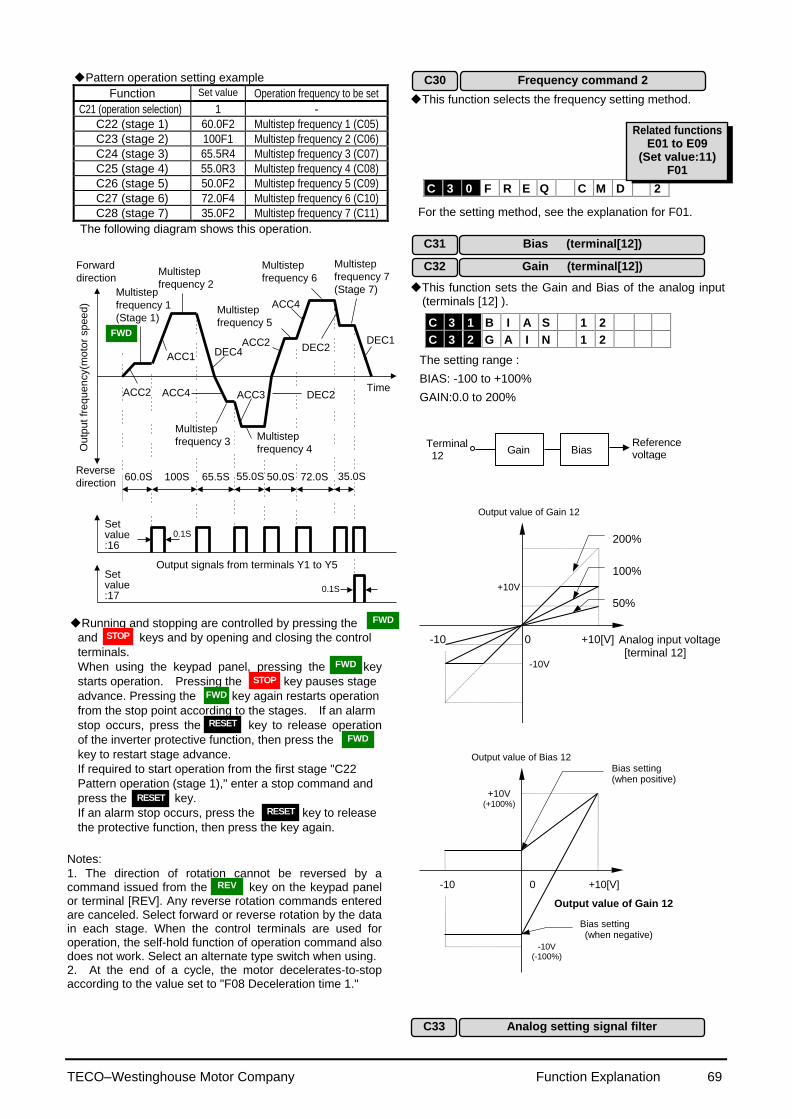
TECO–Westinghouse Motor Company Function Explanation 69
C 3 0 F R E Q C M D 2
Pattern operation setting example
Function Set value Operation frequency to be set
C21 (operation selection) 1 -
C22 (stage 1) 60.0F2 Multistep frequency 1 (C05)
C23 (stage 2) 100F1 Multistep frequency 2 (C06)
C24 (stage 3) 65.5R4 Multistep frequency 3 (C07)
C25 (stage 4) 55.0R3 Multistep frequency 4 (C08)
C26 (stage 5) 50.0F2 Multistep frequency 5 (C09)
C27 (stage 6) 72.0F4 Multistep frequency 6 (C10)
C28 (stage 7) 35.0F2 Multistep frequency 7 (C11)
The following diagram shows this operation.
Forward
direction
Reverse
direction
TimeACC2
ACC1 DEC4
ACC4 ACC3 DEC2
ACC2
ACC4
DEC2DEC1
60.0S 100S 65.5S 55.0S 50.0S 72.0S 35.0S
0.1S
0.1S
Setvalue:16
Output signals from terminals Y1 to Y5
Ou
tpu
t fr
eq
ue
ncy(m
oto
r sp
ee
d)
Multistep
frequency 1
(Stage 1)
Multistep
frequency 2
Multistep
frequency 3Multistep
frequency 4
Multistep
frequency 5
Multistep
frequency 6
Multistep
frequency 7
(Stage 7)
Setvalue:17
Running and stopping are controlled by pressing the
and keys and by opening and closing the control
terminals.
When using the keypad panel, pressing the key
starts operation. Pressing the key pauses stage
advance. Pressing the key again restarts operation
from the stop point according to the stages. If an alarm
stop occurs, press the key to release operation
of the inverter protective function, then press the
key to restart stage advance.
If required to start operation from the first stage "C22
Pattern operation (stage 1)," enter a stop command and
press the key.
If an alarm stop occurs, press the key to release
the protective function, then press the key again.
Notes:
1. The direction of rotation cannot be reversed by a command issued from the key on the keypad panel or terminal [REV]. Any reverse rotation commands entered are canceled. Select forward or reverse rotation by the data in each stage. When the control terminals are used for operation, the self-hold function of operation command also does not work. Select an alternate type switch when using. 2. At the end of a cycle, the motor decelerates-to-stop according to the value set to "F08 Deceleration time 1."
This function selects the frequency setting method.
For the setting method, see the explanation for F01.
This function sets the Gain and Bias of the analog input (terminals [12] ).
The setting range :
BIAS: -100 to +100%
GAIN:0.0 to 200%
Terminal 12
Gain Bias Reference voltage
-10 0 +10[V]
Output value of Gain 12
Analog input voltage [terminal 12]
200%
100%
50%
+10V
-10V
-10 0 +10[V]
Output value of Bias 12
Output value of Gain 12
Bias setting (when positive)
Bias setting (when negative)
+10V (+100%)
-10V (-100%)
C 3 1 B I A S 1 2
C 3 2 G A I N 1 2
C30 Frequency command 2
C31 Bias (terminal[12])
C32 Gain (terminal[12])
C33
Analog setting signal filter
Related functions E01 to E09
(Set value:11) F01
FWD
FWD
FWD
FWD
FWD
REV
STOP
STOP
RESET
RESET
RESET
TECO–Westinghouse Motor Company Function Explanation 70
Analog signals input from control terminal 12 or C1 may
contain noise, which renders control unstable. This function adjusts the time constant of the input filter to remove the effects of noise.
Setting range: 0.00 to 5.00 seconds
An excessive setting delays control response though stabilizing control. A set value too small speeds up control response but renders control unstable.
If the optimum value is not known, adjust the setting when control is unstable or response is delayed. Note: The set value is commonly applied to terminals 12 and C1. For input of PID feedback amount, the PID control feedback filter (set in H25) is used.
C 3 3 R E F F I L T E R
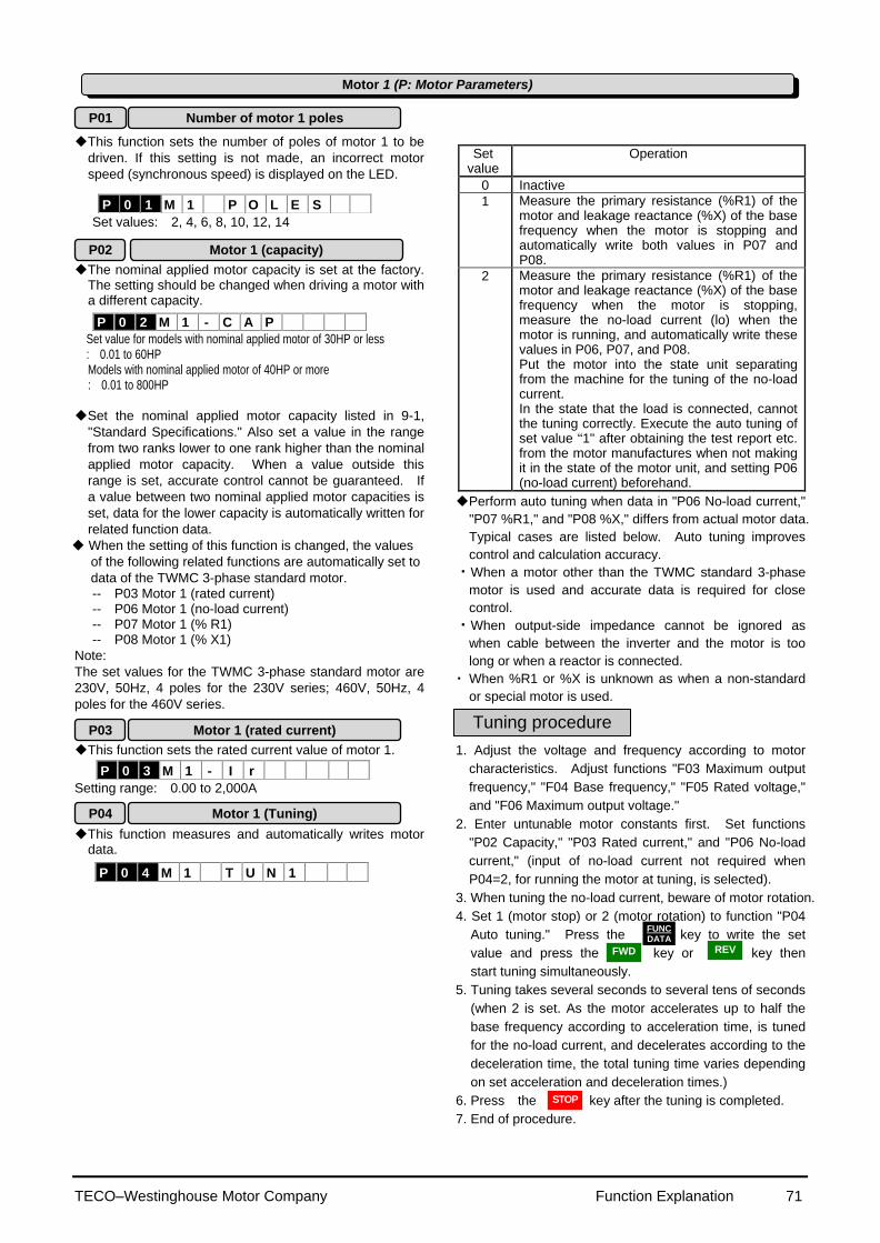
TECO–Westinghouse Motor Company Function Explanation 71
This function sets the number of poles of motor 1 to be
driven. If this setting is not made, an incorrect motor
speed (synchronous speed) is displayed on the LED.
Set values: 2, 4, 6, 8, 10, 12, 14
The nominal applied motor capacity is set at the factory.
The setting should be changed when driving a motor with a different capacity.
Set value for models with nominal applied motor of 30HP or less : 0.01 to 60HP Models with nominal applied motor of 40HP or more : 0.01 to 800HP
Set the nominal applied motor capacity listed in 9-1,
"Standard Specifications." Also set a value in the range
from two ranks lower to one rank higher than the nominal
applied motor capacity. When a value outside this
range is set, accurate control cannot be guaranteed. If
a value between two nominal applied motor capacities is
set, data for the lower capacity is automatically written for
related function data.
When the setting of this function is changed, the values
of the following related functions are automatically set to
data of the TWMC 3-phase standard motor.
-- P03 Motor 1 (rated current) -- P06 Motor 1 (no-load current) -- P07 Motor 1 (% R1) -- P08 Motor 1 (% X1)
Note:
The set values for the TWMC 3-phase standard motor are
230V, 50Hz, 4 poles for the 230V series; 460V, 50Hz, 4
poles for the 460V series. This function sets the rated current value of motor 1.
Setting range: 0.00 to 2,000A This function measures and automatically writes motor
data.
Set value
Operation
0 Inactive
1 Measure the primary resistance (%R1) of the motor and leakage reactance (%X) of the base frequency when the motor is stopping and automatically write both values in P07 and P08.
2 Measure the primary resistance (%R1) of the motor and leakage reactance (%X) of the base frequency when the motor is stopping, measure the no-load current (lo) when the motor is running, and automatically write these values in P06, P07, and P08. Put the motor into the state unit separating from the machine for the tuning of the no-load current. In the state that the load is connected, cannot the tuning correctly. Execute the auto tuning of set value “1" after obtaining the test report etc. from the motor manufactures when not making it in the state of the motor unit, and setting P06 (no-load current) beforehand.
Perform auto tuning when data in "P06 No-load current,"
"P07 %R1," and "P08 %X," differs from actual motor data.
Typical cases are listed below. Auto tuning improves
control and calculation accuracy.
・When a motor other than the TWMC standard 3-phase
motor is used and accurate data is required for close
control.
・When output-side impedance cannot be ignored as
when cable between the inverter and the motor is too
long or when a reactor is connected.
・ When %R1 or %X is unknown as when a non-standard
or special motor is used.
1. Adjust the voltage and frequency according to motor
characteristics. Adjust functions "F03 Maximum output
frequency," "F04 Base frequency," "F05 Rated voltage,"
and "F06 Maximum output voltage."
2. Enter untunable motor constants first. Set functions
"P02 Capacity," "P03 Rated current," and "P06 No-load
current," (input of no-load current not required when
P04=2, for running the motor at tuning, is selected).
3. When tuning the no-load current, beware of motor rotation.
4. Set 1 (motor stop) or 2 (motor rotation) to function "P04
Auto tuning." Press the key to write the set
value and press the key or key then
start tuning simultaneously.
5. Tuning takes several seconds to several tens of seconds
(when 2 is set. As the motor accelerates up to half the
base frequency according to acceleration time, is tuned
for the no-load current, and decelerates according to the
deceleration time, the total tuning time varies depending
on set acceleration and deceleration times.)
6. Press the key after the tuning is completed.
7. End of procedure.
P 0 1 M 1 P O L E S
P 0 2 M 1 - C A P
P 0 3 M 1 - I r
P 0 4 M 1 T U N 1
Motor 1 (P: Motor Parameters)
P01
Number of motor 1 poles
P03 Motor 1 (rated current)
P04 Motor 1 (Tuning)
P02 Motor 1 (capacity)
Tuning procedure
FUNC DATA
FWD REV
STOP
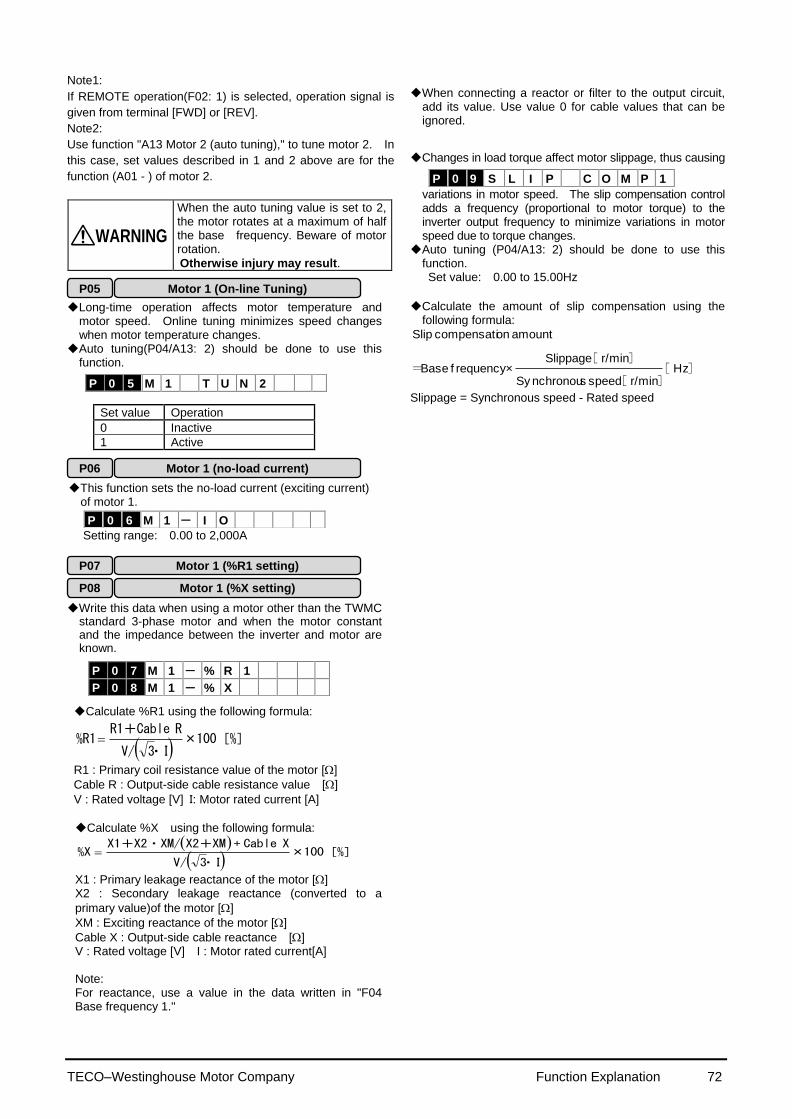
TECO–Westinghouse Motor Company Function Explanation 72
Note1:
If REMOTE operation(F02: 1) is selected, operation signal is
given from terminal [FWD] or [REV].
Note2:
Use function "A13 Motor 2 (auto tuning)," to tune motor 2. In
this case, set values described in 1 and 2 above are for the
function (A01 - ) of motor 2.
WARNING When the auto tuning value is set to 2, the motor rotates at a maximum of half the base frequency. Beware of motor rotation.
Otherwise injury may result.
Long-time operation affects motor temperature and
motor speed. Online tuning minimizes speed changes when motor temperature changes.
Auto tuning(P04/A13: 2) should be done to use this function.
Set value Operation
0 Inactive
1 Active
This function sets the no-load current (exciting current)
of motor 1.
Setting range: 0.00 to 2,000A
Write this data when using a motor other than the TWMC
standard 3-phase motor and when the motor constant and the impedance between the inverter and motor are known.
Calculate %R1 using the following formula:
100[%]×
・I3V/
R R1+Cable%R1
R1 : Primary coil resistance value of the motor []
Cable R : Output-side cable resistance value []
V : Rated voltage [V] I: Motor rated current [A]
Calculate %X using the following formula:
100[%]×・I3V/
X Cable+X2+XMX1+X2・XM/%X
X1 : Primary leakage reactance of the motor [] X2 : Secondary leakage reactance (converted to a
primary value)of the motor []
XM : Exciting reactance of the motor []
Cable X : Output-side cable reactance [] V : Rated voltage [V] I : Motor rated current[A] Note: For reactance, use a value in the data written in "F04 Base frequency 1."
When connecting a reactor or filter to the output circuit,
add its value. Use value 0 for cable values that can be ignored.
Changes in load torque affect motor slippage, thus causing
variations in motor speed. The slip compensation control adds a frequency (proportional to motor torque) to the inverter output frequency to minimize variations in motor speed due to torque changes.
Auto tuning (P04/A13: 2) should be done to use this function. Set value: 0.00 to 15.00Hz
Calculate the amount of slip compensation using the
following formula:
][][
][= Hz
r/minspeed sSy nchronou
r/minSlippage×f requency Base
amount oncompensati Slip
Slippage = Synchronous speed - Rated speed
P 0 9 S L I P C O M P 1
P 0 5 M 1 T U N 2
P 0 6 M 1 - I O
P 0 7 M 1 - % R 1
P 0 8 M 1 - % X
P06 Motor 1 (no-load current)
P05 Motor 1 (On-line Tuning)
P09 Slip compensation control
P08 Motor 1 (%X setting)
P07 Motor 1 (%R1 setting)
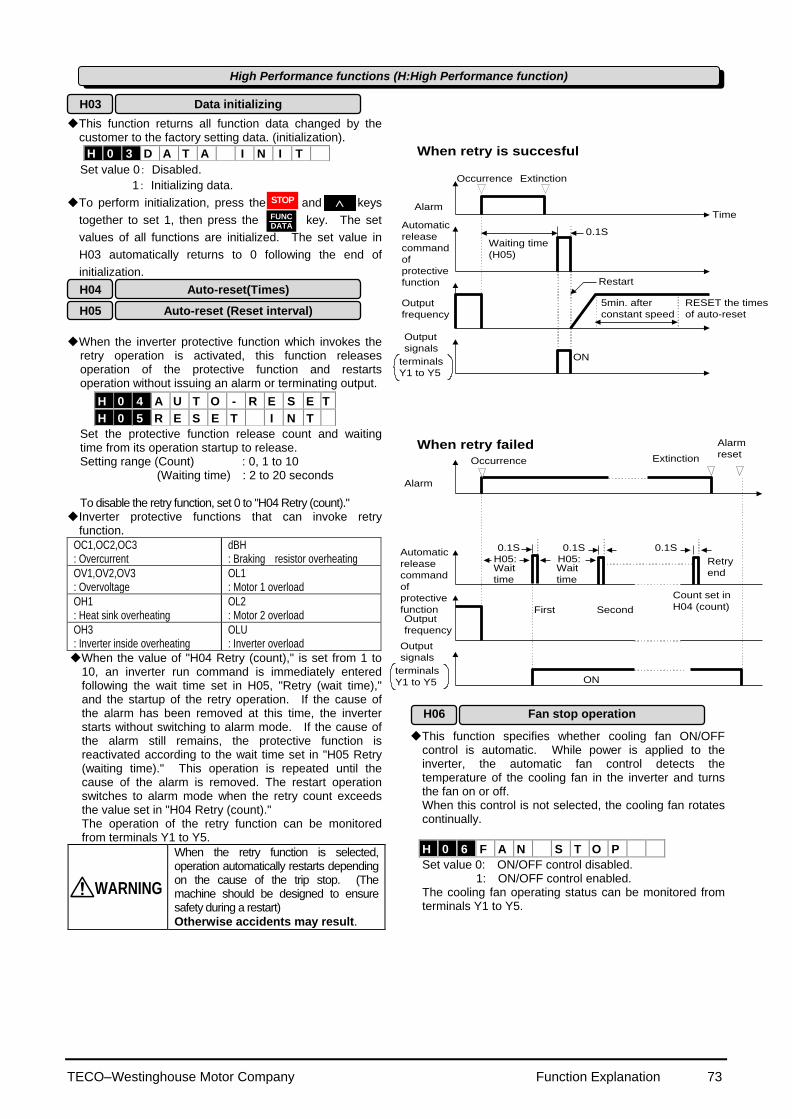
TECO–Westinghouse Motor Company Function Explanation 73
This function returns all function data changed by the
customer to the factory setting data. (initialization).
Set value 0: Disabled.
1: Initializing data.
To perform initialization, press the and keys
together to set 1, then press the key. The set
values of all functions are initialized. The set value in
H03 automatically returns to 0 following the end of
initialization.
When the inverter protective function which invokes the
retry operation is activated, this function releases operation of the protective function and restarts operation without issuing an alarm or terminating output.
Set the protective function release count and waiting time from its operation startup to release. Setting range (Count) : 0, 1 to 10
(Waiting time) : 2 to 20 seconds To disable the retry function, set 0 to "H04 Retry (count)."
Inverter protective functions that can invoke retry function.
OC1,OC2,OC3 : Overcurrent
dBH : Braking resistor overheating
OV1,OV2,OV3 : Overvoltage
OL1 : Motor 1 overload
OH1 : Heat sink overheating
OL2 : Motor 2 overload
OH3 : Inverter inside overheating
OLU : Inverter overload
When the value of "H04 Retry (count)," is set from 1 to 10, an inverter run command is immediately entered following the wait time set in H05, "Retry (wait time)," and the startup of the retry operation. If the cause of the alarm has been removed at this time, the inverter starts without switching to alarm mode. If the cause of the alarm still remains, the protective function is reactivated according to the wait time set in "H05 Retry (waiting time)." This operation is repeated until the cause of the alarm is removed. The restart operation switches to alarm mode when the retry count exceeds the value set in "H04 Retry (count)." The operation of the retry function can be monitored from terminals Y1 to Y5.
WARNING
When the retry function is selected, operation automatically restarts depending on the cause of the trip stop. (The machine should be designed to ensure safety during a restart)
Otherwise accidents may result.
When retry is succesful
Alarm
Automatic
release
command
of
protective
function
Time
Output
frequency
When retry failed
Alarm
Extinction
Waiting time
(H05)
0.1S
Restart
ON
Occurrence
Occurrence Extinction
H05:Wait
time
0.1S
H05:Wait
time
0.1S 0.1S
Retry
end
First Second
Count set in
H04 (count)
Output
frequency
ON
Alarm
reset
Output
signals
terminals
Y1 to Y5
Automatic
release
command
of
protective
function
Output
signals
terminals
Y1 to Y5
5min. after
constant speed
RESET the times
of auto-reset
This function specifies whether cooling fan ON/OFF
control is automatic. While power is applied to the inverter, the automatic fan control detects the temperature of the cooling fan in the inverter and turns the fan on or off. When this control is not selected, the cooling fan rotates continually.
H 0 6 F A N S T O P
Set value 0: ON/OFF control disabled. 1: ON/OFF control enabled.
The cooling fan operating status can be monitored from terminals Y1 to Y5.
H 0 3 D A T A I N I T
H 0 4 A U T O - R E S E T
H 0 5 R E S E T I N T
High Performance functions (H:High Performance function)
H03 Data initializing
H04 Auto-reset(Times)
H05 Auto-reset (Reset interval)
H06 Fan stop operation
FUNC DATA
STOP
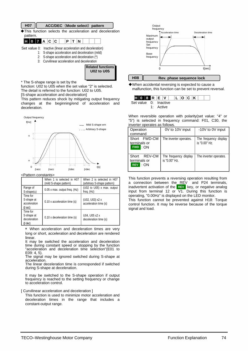
TECO–Westinghouse Motor Company Function Explanation 74
This function selects the acceleration and deceleration pattern.
Set value 0: Inactive (linear acceleration and deceleration)
1: S-shape acceleration and deceleration (mild) 2: S-shape acceleration and deceleration (*) 3: Curvilinear acceleration and deceleration
* The S-shape range is set by the function: U02 to U05 when the set value "2" is selected. The detail is referred to the function: U02 to U05. [S-shape acceleration and deceleration] This pattern reduces shock by mitigating output frequency changes at the beginning/end of acceleration and deceleration.
Output frequency
0
f[Hz]
t[s] dec dec acc acc
Arbitrary S-shape
Mild S-shape ern
<Pattern constants>
When 1 is selected in H07 (mild S-shape pattern)
When 2 is selected in H07 (arbitrary S-shape pattern)
Range of
S-shape() 0.05 x max. output freq. (Hz)
(U02 to U05) x max. output freq. (Hz)
Time for S-shape at acceleration
( acc)
0.10 x acceleration time (s) (U02, U03) x2 x acceleration time (s)
Time for S-shape at deceleration
( dec)
0.10 x deceleration time (s) U04, U05 x2 x deceleration time (s)
When acceleration and deceleration times are very
long or short, acceleration and deceleration are rendered linear. It may be switched the acceleration and deceleration time during constant speed or stopping by the function "acceleration and deceleration time selection"(E01 to E09: 4, 5). The signal may be ignored switched during S-shape at acceleration. The linear deceleration time is corresponded if switched during S-shape at deceleration. It may be switched to the S-shape operation if output frequency is reached to the setting frequency or change to acceleration control.
[ Curvilinear acceleration and deceleration ] This function is used to minimize motor acceleration and deceleration times in the range that includes a constant-output range.
Deceleration time
Maximum output frequency
Output frequency
Base frequency
t[sec] 0
Acceleration time
Set frequency
When accidental reversing is expected to cause a
malfunction, this function can be set to prevent reversal.
H 0 8 R E V L O C K
Set value 0: Inactive 1: Active
When reversible operation with polarity(set value: "4" or "5") is selected in frequency command: F01, C30, the inverter operates as follows.
Operation command
0V to 10V input -10V to 0V input
Short FWD-CM terminals or : ON
The inverter operates. The frequency display is "0.00" Hz.
Short REV-CM terminals or : ON
The frequency display is "0.00" Hz.
The inverter operates.
This function prevents a reversing operation resulting from a connection between the REV and P24 terminals, inadvertent activation of the key, or negative analog input from terminal 12 or V1. During this function is operating, "0.00Hz" is displayed on the LED monitor. This function cannot be prevented against H18: Torque control function. It may be reverse because of the torque signal and load.
ACC/DEC (Mode select) pattern H07
H 0 7 A C C P T N
Related functions U02 to U05
H08 Rev. phase sequence lock
FWD
REV
REV
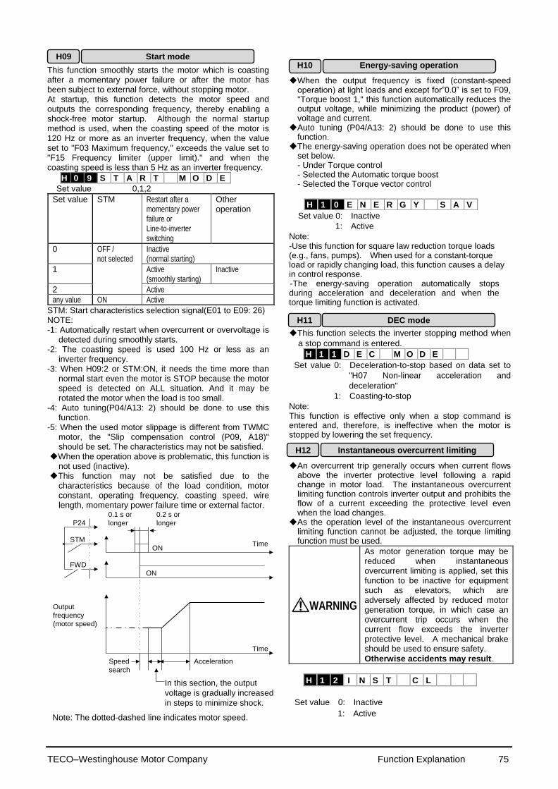
TECO–Westinghouse Motor Company Function Explanation 75
This function smoothly starts the motor which is coasting after a momentary power failure or after the motor has been subject to external force, without stopping motor. At startup, this function detects the motor speed and outputs the corresponding frequency, thereby enabling a shock-free motor startup. Although the normal startup method is used, when the coasting speed of the motor is 120 Hz or more as an inverter frequency, when the value set to "F03 Maximum frequency," exceeds the value set to "F15 Frequency limiter (upper limit)." and when the coasting speed is less than 5 Hz as an inverter frequency.
H 0 9 S T A R T M O D E
Set value 0,1,2
Set value STM Restart after a momentary power failure or Line-to-inverter switching
Other operation
0 OFF / not selected
Inactive (normal starting)
1 Active (smoothly starting)
Inactive
2 Active
any value ON Active
STM: Start characteristics selection signal(E01 to E09: 26) NOTE: -1: Automatically restart when overcurrent or overvoltage is
detected during smoothly starts. -2: The coasting speed is used 100 Hz or less as an
inverter frequency. -3: When H09:2 or STM:ON, it needs the time more than
normal start even the motor is STOP because the motor speed is detected on ALL situation. And it may be rotated the motor when the load is too small.
-4: Auto tuning(P04/A13: 2) should be done to use this function.
-5: When the used motor slippage is different from TWMC motor, the "Slip compensation control (P09, A18)" should be set. The characteristics may not be satisfied.
When the operation above is problematic, this function is not used (inactive).
This function may not be satisfied due to the characteristics because of the load condition, motor constant, operating frequency, coasting speed, wire length, momentary power failure time or external factor.
P24
STM
FWD
Time
0.1 s or
longer
0.2 s or
longer
ON
Time
Output
frequency
(motor speed)
Speed
search
In this section, the output
voltage is gradually increased
in steps to minimize shock.
Acceleration
ON
Note: The dotted-dashed line indicates motor speed.
When the output frequency is fixed (constant-speed operation) at light loads and except for”0.0” is set to F09, "Torque boost 1," this function automatically reduces the output voltage, while minimizing the product (power) of voltage and current.
Auto tuning (P04/A13: 2) should be done to use this function.
The energy-saving operation does not be operated when set below. - Under Torque control - Selected the Automatic torque boost - Selected the Torque vector control
Set value 0: Inactive
1: Active
Note: -Use this function for square law reduction torque loads (e.g., fans, pumps). When used for a constant-torque load or rapidly changing load, this function causes a delay in control response. -The energy-saving operation automatically stops during acceleration and deceleration and when the torque limiting function is activated.
This function selects the inverter stopping method when
a stop command is entered.
H 1 1 D E C M O D E
Set value 0: Deceleration-to-stop based on data set to
"H07 Non-linear acceleration and
deceleration"
1: Coasting-to-stop
Note: This function is effective only when a stop command is entered and, therefore, is ineffective when the motor is stopped by lowering the set frequency.
An overcurrent trip generally occurs when current flows
above the inverter protective level following a rapid change in motor load. The instantaneous overcurrent limiting function controls inverter output and prohibits the flow of a current exceeding the protective level even when the load changes.
As the operation level of the instantaneous overcurrent limiting function cannot be adjusted, the torque limiting function must be used.
WARNING
As motor generation torque may be reduced when instantaneous overcurrent limiting is applied, set this function to be inactive for equipment such as elevators, which are adversely affected by reduced motor generation torque, in which case an overcurrent trip occurs when the current flow exceeds the inverter protective level. A mechanical brake should be used to ensure safety.
Otherwise accidents may result.
H 1 2 I N S T C L
Set value 0: Inactive
1: Active
H 1 0 E N E R G Y S A V
H09 Start mode
H12 Instantaneous overcurrent limiting
H10 Energy-saving operation
H11 DEC mode
H09 Start mode
TECO–Westinghouse Motor Company Function Explanation 76
Instantaneous switching to another power line (when the power of an operating motor is cut off or power failure occurs) creates a large phase difference between the line voltage and the voltage remaining in the motor, which may cause electrical or mechanical failure. To rapidly switch power lines, enter the remaining voltage attenuation time to wait for the voltage remaining in the motor to attenuate. This function operates at restart after a momentary power failure.
H 1 3 R E S T A R T T
Setting range: 0.1 to 5.0 seconds When the momentary power failure time is shorter than
the wait time value, a restart occurs following the wait time. When the power failure time is longer than the wait time value, a restart occurs when the inverter is ready to operate (after about 0.2 to 0.5 second).
This function determines the reduction rate of the output
frequency for synchronizing the inverter output frequency and the motor speed. This function is also used to reduce the frequency and thereby prevent stalling under a heavy load during normal operation.
H 1 4 F A L L R A T E
Setting range: 0.00, 0.01 to 100.00 Hz/s
When 0.00 is set, the frequency is reduced according to
the set deceleration time.
Note:
A too large frequency reduction rate is may temporarily
increase the regeneration energy from the load and
invoke the overvoltage protective function. Conversely,
a rate that is too small extends the operation time of the
current limiting function and may invoke the inverter
overload protective function.
This function is for when 2 (deceleration-to-stop at power
failure) or 3 (operation continuation) is set to "F14 Restart after momentary power failure (operation selection)." Either function starts a control operation if the main circuit DC voltage drops below the set operation continuation level.
H 1 5 H O L D V
Setting range 230 V series: 200 to 300V
460 V series: 400 to 600V When power supply voltage to the inverter is high,
control can be stabilized even under an excessive load by raising the operation continuation level. However, when the level is too high, this function activates during normal operation and causes unexpected motion. Please contact TWMC electric when changing the initial value.
As the power to an external operation circuit (relay sequence) and the main power to the inverter is generally cut off at a power failure, the operation command issued to the inverter is also cut off. This function sets the time an operation command is to be held in the inverter. If a power failure lasts beyond the self-hold time, power-off is assumed, automatic restart mode is released, and the inverter starts operation at normal mode when power is applied again. (This time can be considered the allowable power failure time.)
H 1 6 S E L F H O L D T
Setting range: 0.0 to 30.0 seconds, 999
When "999" is set, an operation command is held (i.e.,
considered a momentary power failure) while control power
in the inverter is being established or until the main circuit
DC voltage is about 100Vdc.
This function controls motor torque according to a command value.
This function automatically extends accelerating time
against acceleration operation of 60 seconds or longer to prevent an inverter trip resulting from a temperature rise in inverter due to overcurrent.
Set value 0: Inactive 1: Active
(When the active drive function is activated, the acceleration time is three times the selected time.)
H 1 9 A U T R E D
H19 Active drive
H16 Auto-restart (OPR command selfhold time) H13 Auto-restart (Restart time)
H14 Auto-restart ( Freq. fall rate)
H15 Auto-restart (Holding DC voltage)
H14 Auto-restart (Freq. fall rate)
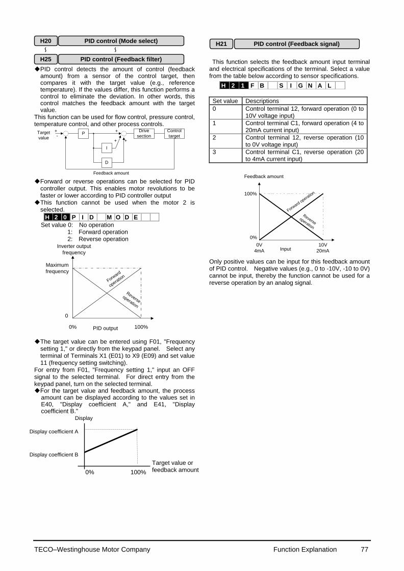
TECO–Westinghouse Motor Company Function Explanation 77
PID control detects the amount of control (feedback amount) from a sensor of the control target, then compares it with the target value (e.g., reference temperature). If the values differ, this function performs a control to eliminate the deviation. In other words, this control matches the feedback amount with the target value.
This function can be used for flow control, pressure control, temperature control, and other process controls.
Target
valueP
Drive
section
Control
target
I
D
+
+ +
+-
Feedback amount
Forward or reverse operations can be selected for PID controller output. This enables motor revolutions to be faster or lower according to PID controller output
This function cannot be used when the motor 2 is selected.
H 2 0 P I D M O D E
Set value 0: No operation 1: Forward operation 2: Reverse operation
Forward
operatio
n
Reverseoperation
Maximum
frequency
0
0% 100%PID output
Inverter output
frequency
The target value can be entered using F01, "Frequency
setting 1," or directly from the keypad panel. Select any terminal of Terminals X1 (E01) to X9 (E09) and set value 11 (frequency setting switching).
For entry from F01, "Frequency setting 1," input an OFF signal to the selected terminal. For direct entry from the keypad panel, turn on the selected terminal. For the target value and feedback amount, the process
amount can be displayed according to the values set in E40, "Display coefficient A," and E41, "Display coefficient B."
This function selects the feedback amount input terminal and electrical specifications of the terminal. Select a value from the table below according to sensor specifications.
Set value Descriptions
0 Control terminal 12, forward operation (0 to 10V voltage input)
1 Control terminal C1, forward operation (4 to 20mA current input)
2 Control terminal 12, reverse operation (10 to 0V voltage input)
3 Control terminal C1, reverse operation (20 to 4mA current input)
Forward
operatio
n
Reverseoperation
100%
0%
0V
4mA
10V
20mAInput
Feedback amount
Only positive values can be input for this feedback amount of PID control. Negative values (e.g., 0 to -10V, -10 to 0V) cannot be input, thereby the function cannot be used for a reverse operation by an analog signal.
H 2 1 F B S I G N A L
Target value or feedback amount
Display
Display coefficient A
Display coefficient B
0% 100%
H21 PID control (Feedback signal)
H25 PID control (Feedback filter)
H20 PID control (Mode select)
~ ~
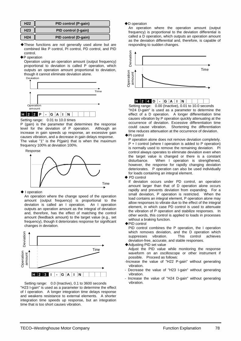
TECO–Westinghouse Motor Company Function Explanation 78
H 2 2 P - G A I N
These functions are not generally used alone but are
combined like P control, PI control, PD control, and PID control.
P operation Operation using an operation amount (output frequency) proportional to deviation is called P operation, which outputs an operation amount proportional to deviation, though it cannot eliminate deviation alone.
Time
Deviation
Operation
amount
Setting range: 0.01 to 10.0 times P (gain) is the parameter that determines the response level for the deviation of P operation. Although an increase in gain speeds up response, an excessive gain causes vibration, and a decrease in gain delays response. The value "1" is the P(gain) that is when the maximum frequency 100% at deviation 100%.
Time
Response
I operation
An operation where the change speed of the operation amount (output frequency) is proportional to the deviation is called an I operation. An I operation outputs an operation amount as the integral of deviation and, therefore, has the effect of matching the control amount (feedback amount) to the target value (e.g., set frequency), though it deteriorates response for significant changes in deviation.
Time
Devia
tion
Op
era
tion
am
ou
nt
Setting range: 0.0 (Inactive), 0.1 to 3600 seconds
"H23 I-gain" is used as a parameter to determine the effect of I operation. A longer integration time delays response and weakens resistance to external elements. A shorter integration time speeds up response, but an integration time that is too short causes vibration.
D operation An operation where the operation amount (output frequency) is proportional to the deviation differential is called a D operation, which outputs an operation amount as the deviation differential and, therefore, is capable of responding to sudden changes.
Time
De
via
tio
nO
pe
ratio
n
am
ou
nt
Setting range: 0.00 (Inactive), 0.01 to 10.0 seconds "H24 D-gain" is used as a parameter to determine the effect of a D operation. A longer differentiation time causes vibration by P operation quickly attenuating at the occurrence of deviation. Excessive differentiation time could cause vibration. Shortening the differentiation time reduces attenuation at the occurrence of deviation.
PI control P operation alone does not remove deviation completely. P + I control (where I operation is added to P operation) is normally used to remove the remaining deviation. PI control always operates to eliminate deviation even when the target value is changed or there is a constant disturbance. When I operation is strengthened, however, the response for rapidly changing deviation deteriorates. P operation can also be used individually for loads containing an integral element.
PD control If deviation occurs under PD control, an operation amount larger than that of D operation alone occurs rapidly and prevents deviation from expanding. For a small deviation, P operation is restricted. When the load contains an integral element, P operation alone may allow responses to vibrate due to the effect of the integral element, in which case PD control is used to attenuate the vibration of P operation and stabilize responses. In other words, this control is applied to loads in processes without a braking function.
PID control PID control combines the P operation, the I operation which removes deviation, and the D operation which suppresses vibration. This control achieves deviation-free, accurate, and stable responses.
Adjusting PID set value Adjust the PID value while monitoring the response waveform on an oscilloscope or other instrument if possible. Proceed as follows:
-Increase the value of "H22 P-gain" without generating vibration.
- Decrease the value of "H23 I-gain" without generating vibration.
- Increase the value of "H24 D-gain" without generating vibration.
H 2 3 I - G A I N
H 2 4 D - G A I N
H22 PID control (P-gain)
H23 PID control (I-gain)
H24 PID control (D-gain)
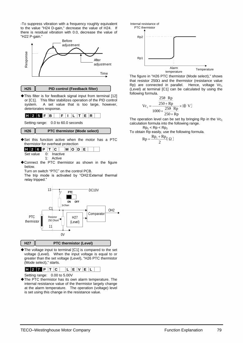
TECO–Westinghouse Motor Company Function Explanation 79
-To suppress vibration with a frequency roughly equivalent to the value "H24 D-gain," decrease the value of H24. If there is residual vibration with 0.0, decrease the value of "H22 P-gain."
Re
sp
on
se
Before
adjustment
After
adjustment
Time
This filter is for feedback signal input from terminal [12]
or [C1]. This filter stabilizes operation of the PID control system. A set value that is too large, however, deteriorates response.
H 2 5 F B F I L T E R
Setting range: 0.0 to 60.0 seconds Set this function active when the motor has a PTC
thermistor for overheat protection
Set value 0: Inactive 1: Active
Connect the PTC thermistor as shown in the figure below.
Turn on switch “PTC” on the control PCB. The trip mode is activated by “OH2:External thermal
relay tripped.”
PTC
thermistorH27
(Level)
ComparatorOH2
DC10V
Resistor
250 Ohom
0V
13
C1
11
ON OFF
PTC
1k Ohom
The voltage input to terminal [C1] is compared to the set
voltage (Level). When the input voltage is equal to or greater than the set voltage (Level), "H26 PTC thermistor (Mode select)," starts.
Setting range: 0.00 to 5.00V The PTC thermistor has its own alarm temperature. The
internal resistance value of the thermistor largely change at the alarm temperature. The operation (voltage) level is set using this change in the resistance value.
Internal resistance of
PTC thermistor
Rp2
Rp1
TemperatureAlarm
temperature The figure in "H26 PTC thermistor (Mode select)," shows
that resistor 250 and the thermistor (resistance value Rp) are connected in parallel. Hence, voltage Vc1 (Level) at terminal [C1] can be calculated by using the following formula.
][・
・
V10
Rp250
Rp2501000
Rp250
Rp250
Vc1
The operation level can be set by bringing Rp in the Vc1 calculation formula into the following range.
Rp1 < Rp < Rp2
To obtain Rp easily, use the following formula.
[Ω]2
RpRpRp 21
H 2 6 P T C M O D E
H26 PTC thermistor (Mode select)
H27 PTC thermistor (Level)
H 2 7 P T C L E V E L
H25 PID control (Feedback filter)
TECO–Westinghouse Motor Company Function Explanation 80
The link function (communication function) provides RS-485 (provided as standard) and bus connections (optional).
The serial link function includes: 1) Monitoring (data monitoring, function data check) 2) Frequency setting 3) Operation command (FWD, REV, and other commands for digital input) 4)Write function data
H 3 0 L I N K F U N C
Setting range: 0 to 3 Communication can be enabled and disabled by a digital input. This function sets the serial link function when communication is enabled.
Set value Frequency command
Operation command
0 Disabled Disabled
1 Enabled Disabled
2 Disabled Enabled
3 Enabled Enabled
The data monitoring and function data write functions are always enabled. Disabling communication using digital input brings about the same result as when "0" is set to this function. When the bus option is installed, this setting selects the function of the option and the RS-485 interface is restricted to monitoring and writing function data.
These functions set the conditions of RS-485 Modbus-RTU communication. Set the conditions according to the upstream device. Refer to technical manual for the protocol. This function sets the station address of RTU.
H 3 1 4 8 5 A D R E S S
Setting range: 1 to 247 This function sets processing at communication error and
sets the error processing timer value.
H 3 2 M O D E O N E R
Setting range: 0 to 3
Set value Processing at communication error
0 Immediate Er 8 trip (forced stop)
1 Continue operation within timer time, Er8 trip after timer time.
2
Continue operation and effect retry within timer time, then invoke an Er8 trip if a communication error occurs. If an error does not occur, continue operation.
3 Continue operation.
H 3 3 T I M E R
Setting range: 0.0 to 60.0 seconds This function sets the baud rate.
H 3 4 B A U D R A T E
Setting range: 0 to 3
Set value Baud rate
0 19200 bit/s
1 9600 bit/s
2 4800 bit/s
3 2400 bit/s
This function sets data length.
H 3 5 L E N G T H
Setting range: 0
Set value Data length
0 8 bit
This function sets the parity bit.
H 3 6 P A R I T Y
Setting range: 0 to 2
Set value Parity bit
0 None
1 Even
2 Odd
This function sets the stop bit.
H 3 7 S T O P B I T S
Setting range: 0, 1
Set value Stop bit
0 2 bit
1 1 bit
The stop bit is automatically configured by the value of the
parity bit. For parity “NONE” the stop bit is 2bits. For
parity “EVEN” or “ODD” the stop bit is 1 bit. In a system where the local station is always accessed
within a specific time, this function detects that access was stopped due to an open-circuit or other fault and invokes an Er 8 trip.
H 3 8 N O R E S t
Setting range: 0 (No detection) 1 to 60 seconds
This function sets the time from when a request is issued
from the upstream device to when a response is returned.
H 3 9 I N T E R V A L
Setting range: 0.00 to 1.00 second
H30 Serial link (Function select)
H31 RS-485 (Address)
H39 RS-485 (Response interval)
~ ~

TECO–Westinghouse Motor Company Function Explanation 81
This function sets the maximum frequency for motor 2
output by the inverter. This function operates the same as "F03 Maximum frequency 1." For details, see the explanation for F03.
This function sets the maximum output frequency in the
constant-torque area of motor 2 (i.e., output frequency at rated output voltage). This function operates the same as "F04 Base frequency 1." For details, see the explanation for F04.
This function sets the rated value of voltage output to motor 2. This function operates the same as "F05 Rated voltage 1." For details, see the explanation for F05.
This function sets the maximum value of the inverter
output voltage of motor 2. This function operates the same as "F06 Maximum voltage 1." For details, see the explanation for F06.
A 0 4 M A X V - 2
This function sets the torque boost function of motor 2.
This function operates the same as "F09 Torque boost 1." For details, see the explanation for F09.
This function sets the function of the electronic thermal overload relay for motor 2. This function operates the same as F10 to F12, "Electronic thermal overload relay 1." For details, see the explanations for F10 to F12.
This function sets the torque vector function of motor 2. This function operates the same as "F42 Torque vector control 1." For details, see the explanation for F42.
This function sets the number of poles of motor 2 to be
driven. This function operates the same as "P01 Number
of motor-1 poles." For details, see the explanation for P01.
This function sets the capacity of motor 2. This function operates the same as "P02 Motor 1 (Capacity)." For details, see the explanation for P02. However, the related motor data functions change to "A12 Motor 2 (Rated current)," "A15 Motor 2 (No-load current)," "A16 Motor 2 (%R1 setting)," and "A17 Motor 2 (%X setting)."
This function sets the rated current of motor 2. This
function operates the same as "P03 Motor 1 (Rated current)." For details, see the explanation for P03.
This function sets the auto tuning of motor 2. This
function operates the same as "P04 Motor 1 (Tuning)." For details, see the explanation for P04.
This function sets the online tuning of motor 2. This
function operates the same as "P05 Motor 1 (On-line tuning)." For details, see the explanation for P05.
This function sets the no-load current of motor 2. This
function operates the same as "P06 Motor 1 (No-load current)." For details, see the explanation for P06.
This function sets %R1 and %X of motor 2. This function operates the same as "P07 Motor 1 (%R1 setting)," and "P08 Motor 1 (%X setting)." For details, see the explanations for P07 and P08.
This function sets the amount of slip compensation for
motor 2. This function operates the same as "P09 Slip compensation control." For details, see the explanation for P09.
Set value : 0.00Hz to 15.00Hz
Calculate the amount of slip compensation using the following formula: Slip compensation amount
][ Hzmin]/r[ speed sSynchronou
min]/r[ Slippagefrequency Base
Slippage = Synchronous speed-Rated speed
A 1 1 M 2 - C A P
A 0 5 T R Q B O O S T 2
A 0 9 T R Q V E C T O R 2
A 0 1 M A X H z - 2
A 1 2 M 2 - I r A 0 2 B A S E H z - 2
A 1 3 M 2 T U N 1
A 0 3 R A T E D V 2
A 1 4 M 2 T U N 2
A 1 5 M 2 - I o
A 0 6 E L C T R N O L 2
A 0 7 O L L E V E L 2
A 0 8 T I M E C N S T 2
A 1 0 M 2 P O L E S
Motor 2 (A: Alternative Motor Parameters)
A01 Maximum frequency2
A02
Base frequency 2
A05
Torque boost 2
A03
Rated voltage 2
A11 Motor 2 (Capacity)
A12 Motor 2 (Rated current)
A06 Electronic thermal overload relay 2 (Select)
A07 Electronic thermal overload relay 2 (Level)
A08 Electronic thermal overload relay 2 (Thermal time constant)
A09 Torque vector control 2
A10 Number of motor-2 poles
A13 Motor 2 (Tuning)
A04
Maximum voltage 2
A14 Motor 2 (On-line tuning)
A15 Motor 2 (No-load current)
A16 Motor 2 (%R1 setting)
A17 Motor 2 (%X setting)
A18 Slip compensation control 2
A 1 6 M 2 - % R 1
A 1 7 M 2 - % X
A 1 8 S L I P C O M P 2

TECO–Westinghouse Motor Company Function Explanation 82
This function becomes effective, when the torque limit
(brake) is used. The inverter controls to increase the output frequency so that torque calculations do not exceed the torque limit (brake) setting ( F41 or E17). (When F41 or E17 is set to 999, it becomes invalid.) This function sets the increment of upper limit for output frequency. When the regeneration avoidance is selected, the resurrection ability can be improved by raising the increment of upper limit. However, the output frequency of the inverter is limited at the frequency limit(high): F15.
U 0 1 U S E R 0 1
Setting range : 0 to 65535
The set value "15" becomes 1Hz. (The set value "1" becomes 1/15Hz)
1st S-shape level at acceleration (start) U02
2nd S-shape level at acceleration (stop) U03
1st S-shape level at deceleration (start) U04
2nd S-shape level at deceleration (stop) U05
When "2" is set in the function code: H07, both curvilinear acceleration and deceleration ranges of S-shape can be set up arbitrarily. The range is the ratio for maximum output frequency 1 (F03) or 2 (A01) .
U 0 2 U S E R 0 2
U 0 3 U S E R 0 3
U 0 4 U S E R 0 4
E
U 0 5 U S E R 0 5
Setting range : 1 to 50%
U05
f1
Output frequency
0
f[Hz]
t[s] tdec tacc
U03
U02
U04
f0
100% value of this function means maximum
frequency (fmax) .
Acceleration time “tacc” and deceleration time “tdec” of upper figure become longer than the linear acceleration time and deceleration time. When the set
acceleration time(F07,E10,E12,E14) is assumed to
be “Ta” and deceleration time(F08,E11,E13,E15) is
assumed to be “Td”, “tacc” and “tdec” can be calculated by the following expressions.
- At acceleration,
100
03U02Umaxf|0f1f|
or,
- At deceleration,
100
05U04Umaxf|0f1f|
Ta)100
03U02U
maxf
0f1f(tacc
Td)100
05U04U
maxf
0f1f(tdec
- At acceleration,
100
03U02Umaxf|0f1f|
or,
- At deceleration,
100
05U04Umaxf|0f1f|
Ta100
03U02U
03U02U
100
maxf
0f1f2tacc
Td100
05U04U
05U04U
100
maxf
0f1f2tdec
Initial value of main DC link capacitor U08
Measured value of main DC link capacitor U09
Data for the life expectancy judgment of the capacitor in main circuit is stored in this function. The electrical discharge time of the capacitor can be measured automatically, and the time of part replacement can be confirmed according to the decrement rate from the factory shipment.
U 0 8 U S E R 0 8
U 0 9 U S E R 0 9
Setting range : 0 to 65535 The electrical discharge time which is measured in the
factory shipment is set to function code U08 as a initial value. This value is different in each inverter.
The electrical discharge time of the capacitor is measured automatically, when the power supply is turned off. And, the result is stored in function code U09. When the power supply is turned off under the conditions as follows, decrement rate (%) to the factory shipment can be measured. Conditions: which has been described to "*Estimation of life expectancy based on maintenance information" of the instruction manual "8-2 periodical inspection".
The result of 10008U
09U is displayed in CAP=xxx.x%
of maintenance information. 85% becomes a standard at the part replacement time.
S-shape clause linear Acceleration and deceleration clause
U : User function
Maximum compensation frequency during braking torque limit U01
TECO–Westinghouse Motor Company Function Explanation 83
When you make measurement of capacity and life
expectancy judgment of capacitor with an actual operating condition, set the value “30” to the function code “E20 to E24”. And write the measurement result U09 with an actual operating condition to the function code U08 as an initial value as early as possible since inverter operation starts. However, life judgment by the measurement result cannot be performed in case of 1 and 2 as below. 1. During inverter operation, a power supply is turned
off and it stops. 2. Cooling fan ON/OFF control is used.
(function code : H 06= 1) Turn off the power supply of inverter, on the conditions at which the inverter has stopped, and a cooling fan is operated. It is not necessary to remove an option card and the connection with a control terminal. As for this "measurement with an actual operating condition", carry out this measurement about 10 times to minimize the error of a measurement result, and make the average value into an initial value. Moreover, when there is 10% or more of change from the last measured value, measurement is disregarded in order to prevent incorrect measurement. Renewal of a display is not carried out.
Set measured value U09 to the initial value U08 after
exchanging capacitors.
Related Functions
E20 to E24
(Set value:30)
PC board capacitor powered on time U10
The accumulation time of the capacitor on PC board
are displayed. The accumulation time of the control power supply multiplied by the life expectancy coefficient defined by the temperature inside the inverter are displayed. Hence, the hours displayed may not agree with the actual operating hours. Since the accumulation time are counted by unit hours, power input for less than one hour will be disregarded. The accumulation time are displayed in TCAP=xxxxxh of maintenance information. The standard at the replacement time is 61,000h. Refer to the manual "8-2 regular check" for the maintenance.
U 1 0 U S E R 1 0
Setting range: 0 to 65535 hours
Clear the accumulation time to 0 hour, after replacing
the PC board on which capacitors are equipped with. There is also PC Board without the capacitor (ex :Control circuit board) not to be cleared the accumulation time. For details, contact TWMC.
Related Functions
E20 to E24
(Set value:30)
Cooling fan operating time U11
The integrated operating hours of the cooling fan are
displayed. Since the integrated hours are counted by unit hours, power input for less than one hour will be disregarded. The integrated hours are displayed in TFAN=xxxxxh of maintenance information. The standard at the replacement time is 40,000h in the inverter of 5HP or less. The standard at the replacement time is 25,000h in the inverter of 7.5HP or more. (Estimated life expectancy of a cooling-fan at
inverter ambient temperature of 40 degree.) The displayed value should be considered as a rough estimate because the actual life of a cooling fan is influenced significantly by the temperature. Refer to the manual "8-2 regular check" for the maintenance.
U 1 1 U S E R 1 1
Setting range : 0 to 65535 hours Clear integrated operating time to 0 hour after replacing
the cooling fan.
Related Functions
E20 to E24
(Set value:30)
Magnetize current vibration damping gain U13
Adjust if Magnetizing current vibration occurred in the
inverter output current .
U 1 3 U S E R 1 3
Setting range: 0 to 32767
Adjust the value from 0 to 2048 as a standard value.
Vibration damping gain becomes 100% in set value 4096.
Slip compensation filter time constant U15
The filter time constant of Slip compensation is set.
U 1 5 U S E R 1 5
Setting range : 0 to 32767
Calculate the filter time constant using the following
formula.
valuesetU15""
2constanttimeFilter
16
[ms]
The response time of the control slows because the
filter time constant is enlarged when a value is set to smaller. However, system becomes steady.
The response time of the control quickens because the
filter time constant becomes smaller, when a set value is enlarged.
Note :Response time quickens when a set value is
enlarged. Therefore, there is a possibility that the output frequency becomes unstable. Please adjust a set value to smaller than factory setting value.
Integral gain of continuous operation at power failure U23
Proportional gain of continuous operation at power failure U24
This function becomes effective, when function code
F14 (Restart mode after momentary power failure) set value is 2 or 3.
U 2 3 U S E R 2 3
U 2 4 U S E R 2 4
Setting range : 0~65535
In case of F14 set value : 2.
When the operation continuation level (H15) is reached, deceleration to a stop occurs. The DC voltage of the main circuit sharpens the deceleration slope, and the inverter collects the inertia energy of the load to maintain the DC bus voltage and controls the motor until it stops, so that the undervoltage protective function is not activated. The deceleration slope is adjusted with U23 and U24. However, the deceleration operation time never
TECO–Westinghouse Motor Company Function Explanation 84
becomes longer than the set deceleration time.
In case of F14 set value : 3.
The output frequency is lowered by the control by which the DC voltage of the main circuit is kept constant from the regeneration energy, so that the inverter may continue operation when momentary power failure occurs. The response is adjusted with U23 and U24 at this time.
Calculate the integral gain using the following formula.
value set23"U"
2gainIntegral
16
[ms]
PI
calculator
H15 Set value
DC voltage of the main circuit
Output frequency command
|f*|
I gain:U23
P gain:U24
|f*|
0
Output frequency command
|f**|
Input phase loss protection U48
This function selects operation of input phase loss or
power supply unbalance protection.
U 4 8 U S E R 4 8
Setting range : 0 to 2
Set value Operation
0 Active (without reactor (ACR/DCR))
1 Active (with reactor (ACR/DCR))
2 Inactive
When "2" is set to U48, protection operation of the inverter to input phase loss or power supply voltage unbalance does not work. If you use it as it is, there is a possibility of damaging an inverter and
failure may result.
RS-485 protocol selection U49
The protocol of RS-485 communication is changed.
U 4 9 U S E R 4 9
Set value : 0, 1
Set value Operation
0 FGI-bus
1 Modbus-RTU
Instruction manual and specifications are prepared about communicative details. Contact TWMC.
When function code F13 (electronic thermal)is set to 2,
both the type of the braking resistor and connection circuit are set. Factory setting is set to nominal applied resistor and the number of resistor is one. When the power load capacities of resistor are increased, set the factory setting properly
U 5 9 U S E R 5 9
Setting range : 0 to A8 (HEX) Setting of ten’s digit ( type selection )
Set value
Resistance
[Ω] Capacity
[W]
Duty cycle
[%ED]
0 - - 10%
1 100 200
2 40 400
3 33 400
4 20 800
5 15 900
6 200 200
7 160 400
8 130 400
9 80 800
A 60 900
Setting of unit’s digit (connection circuit selection)
Set
val
ue
Braking-resistor *1) Duty cycle
[%ED]
Synthetic resistance
[Ω]
Power consumption per
resistance [comparatively]
Use number Connection circuit
0 1 DBP
10% R 100%
1 2 DBP
20% 2R 50%
2 2 DBP
20% (1/2)R 50%
3 4 DBP
40% R 25%
4 3 DBP
30% 3R 33%
5 6 DBP
50% (3/2)R 17%
6 9 DBP
50% R 11%
7 4 DBP
40% 4R 25%
8 8 DBP
50% 2R 12.5%
1) It is limited by the %ED value of the braking transistor inside the inverter.
CAUTION !

TECO–Westinghouse Motor Company Function Explanation 85
! CAUTION
Set the function code both “ F13” and “U59 ” before
operating the inverter, and don’t change the functions during operation. The integrated thermal data are cleared immediately, when function code “ F13” or “U59 ” are changed. The overheat protection of resistor becomes invalid. When the function code “ F13” or “U59 ” are changed in the state where temperature rose, the overheat protection of resistor becomes invalid, too.
As there is a possibility of damaging the inverter, the
resistor value less than standard applied value should not be available.
Make into one kind the resistor used as combination
conditions for a braking resistor, and connect it so that the electric power is consumed equally in each resistor.
When the resistor which is instead of DB***-2C/4C are
used as External braking resistor, function code F13 should be set to “0”.
When resistor values less than Standard applied
resistor value is set to the function code, regeneration operation is invalid. OU alarm will be occurred.
If connection of resistor and setting value of resistor is
not corresponded, there is a possibility of damaging the resistor and the inverter.
Caution or failure may result.
Function for manufacturer
[40HP or more is corresponded] U59
This function is available to release the overheating alarm (OH1) at the DC fan broken.
U 5 9 U S E R 5 9
Set value : 00, 01
Set value Operation
00 OH1 alarm at DC fan broken
01 No alarm at DC fan broken
! CAUTION
It causes overheating trip (OH1,OH3) in the inverter,
and the life time decrease such as electrolytic capacitors on the PCB in the unit by a partial rise temperature, and there is a possibility to the worst unit damage when left with the DC fan for an internal stir stops. Be sure that set it to the fan exchange and the factory setting value again promptly after the DC fan for an internal stir stops. (Contact the fan exchange procedure TWMC Electric.)
Failure may result.
Regeneration avoidance at deceleration U60
This function is available, when torque limit (brake) of
F41( or E17) is set to “0%”.
U 6 0 U S E R 6 0
Set value : 0, 1
Set value Operation
0 Torque limit operation
(for high response use)
1 OU alarm avoidance operation
(for only deceleration or Large inertia use )
If function code U60 is set to “0”, braking torque is kept
to about “0%” under acceleration, deceleration, constant speed state. Output frequency is controlled in correspond to the rapid change in motor load to prevent OU alarm. Deceleration time becomes longer than the set deceleration time (F08).
In case of setting value U60:1, Compared with setting
value "0", it controls not to perform torque limit operation only at the deceleration time, but to prevent the rise of the DC voltage of the main circuit, and avoid OU alarm. At this time, although deceleration time becomes longer than a setting value of F08, it becomes shorter than setting value"0" of U60. It may occur OU alarm, if load changes rapidly during deceleration.
Voltage detect offset and gain adjustment U61
40HP/CT, 50HP/VT or more :
It adjusts, only when a print board is replaced by maintenance, etc. If not necessary, do not use this function.
U 6 1 U S E R 6 1
Set value : 0, 1, 2
Inverter capacity
Operation
30HP/CT or 40HP/VT or
less 0:Inactive(fixed)
40HPCT 50HP/VT or
more
0:Inactive
1:Voltage detect offset adjustment
2:Voltage detect gain adjustment
Set the function code in the following procedure.
If the inverter are operated without this adjustment after replacing the PC board, normal operation may not be able to be performed.
(Offset adjustment) 1) Confirm that the main power supply is turned ON,
the motor wiring are connected and the motor has stopped (inverter operation command is OFF).
2) When the data of U61 is changed to "1", and the FUNC/DATA key is ON, the offset self adjustment is
started. The display of “storing" of the keypad
panel disappears several seconds later. When the set value returns to "0", adjustment is completed. If the main power supply is turned OFF, while outputting alarm, motor is driving, coast-to-stop command(BX) is ON and this adjustment is started,
the inverter becomes “Er7:TUNING ERROR".
In this case, start the adjustment after removing the above-mentioned factor.

TECO–Westinghouse Motor Company Function Explanation 86
(Gain adjustment) 1) Drive the motor in an arbitrary frequency of about
10 to 60Hz (However, constant speed) after executing the above-mentioned offset adjustment. (U61:1) At this time, gain adjustment is available unrelated to the load state.
2) When the data of U61 is changed to "2", and the FUNC/DATA key is ON, the gain self adjustment is
started. The display of “storing" of the keypad
panel disappears several seconds to 30 seconds later. When the set value returns to "0", adjustment is completed. If inverter is not operated, this adjustment is not available.
Motor overload memory retention U89
This is Motor overload memory (Electrical thermal O/L
relay) retention selection at power up.
U 8 9 U S E R 8 9
Setting range: 0, 1
Set value Operation
0 Inactive When power up the drive, Motor Overload data is reset.
1
Active. When power is down, the drive stores Motor overload data and uses this data at next power up.
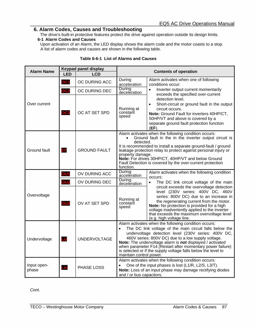
EQ5 AC Drive Operations Manual
_______________________________________________________________________ TECO – Westinghouse Motor Company Alarm Codes & Causes 87
6. Alarm Codes, Causes and Troubleshooting The drive’s built-in protective features protect the drive against operation outside its design limits.
6-1 Alarm Codes and Causes Upon activation of an Alarm, the LED display shows the alarm code and the motor coasts to a stop. A list of alarm codes and causes are shown in the following table.
Table 6-6-1 List of Alarms and Causes
Alarm Name Keypad panel display Contents of operation LED LCD
Over current
OC1 OC DURING ACC During acceleration
Alarm activates when one of following conditions occur: • Inverter output current momentarily
exceeds the specified over-current detection level.
• Short-circuit or ground fault in the output circuit occurs.
Note: Ground Fault for inverters 40HP/CT, 50HP/VT and above is covered by a separate ground fault protection function (EF).
OC2 OC DURING DEC During deceleration
OC3 OC AT SET SPD Running at constant speed
Ground fault EF GROUND FAULT
Alarm activates when the following condition occurs: • Ground fault in the in the inverter output circuit is
detected. It is recommended to install a separate ground-fault / ground leakage protection relay to protect against personal injury or property damage. Note: For drives 30HP/CT, 40HP/VT and below Ground Fault Detection is covered by the over-current protection function.
Overvoltage
OU1 OV DURING ACC During acceleration
Alarm activates when the following condition occurs: • The DC link circuit voltage of the main
circuit exceeds the overvoltage detection level (230V series: 400V DC, 460V series: 800V DC) due to an increase in the regenerating current from the motor.
Note: No protection is provided for a high voltage inadvertently applied to the inverter that exceeds the maximum overvoltage level (e.g. high voltage line.
OU2 OV DURING DEC During deceleration
OU3 OV AT SET SPD Running at constant speed
Undervoltage LU UNDERVOLTAGE
Alarm activates when the following condition occurs: • The DC link voltage of the main circuit falls below the
undervoltage detection level (230V series: 400V DC, 460V series: 800V DC) due to a low supply voltage.
Note: The undervoltage alarm is not displayed / activated when parameter F14 (Restart after momentary power failure) is selected or if the supply voltage falls below the level to maintain control power.
Input open-phase Lin PHASE LOSS
Alarm activates when the following condition occurs: • One of the input phases is lost (L1/R, L2/S, L3/T). Note: Loss of an input phase may damage rectifying diodes and / or bus capacitors.
Cont.
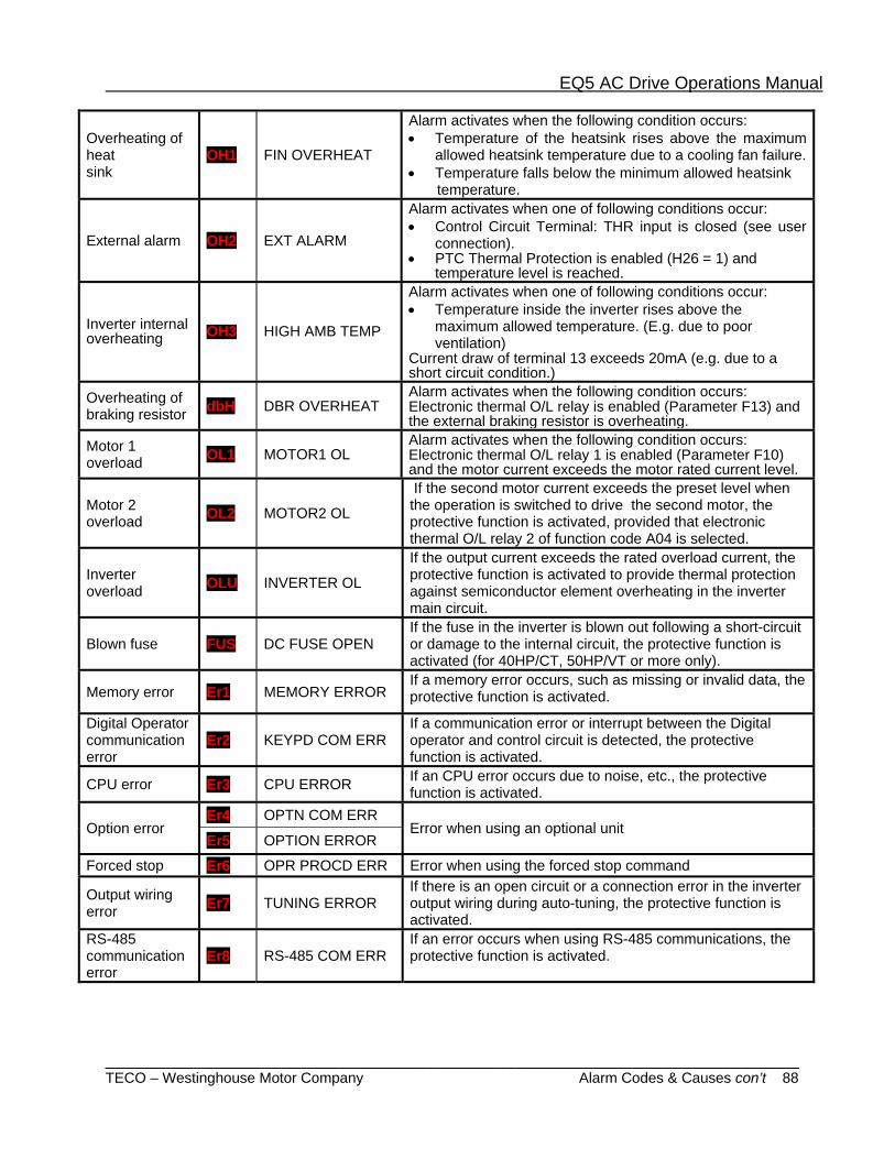
EQ5 AC Drive Operations Manual
_______________________________________________________________________ TECO – Westinghouse Motor Company Alarm Codes & Causes con’t 88
Overheating of heat sink
OH1 FIN OVERHEAT
Alarm activates when the following condition occurs: • Temperature of the heatsink rises above the maximum
allowed heatsink temperature due to a cooling fan failure.• Temperature falls below the minimum allowed heatsink temperature.
External alarm OH2 EXT ALARM
Alarm activates when one of following conditions occur: • Control Circuit Terminal: THR input is closed (see user
connection). • PTC Thermal Protection is enabled (H26 = 1) and
temperature level is reached.
Inverter internal overheating OH3 HIGH AMB TEMP
Alarm activates when one of following conditions occur: • Temperature inside the inverter rises above the
maximum allowed temperature. (E.g. due to poor ventilation)
Current draw of terminal 13 exceeds 20mA (e.g. due to a short circuit condition.)
Overheating of braking resistor dbH DBR OVERHEAT
Alarm activates when the following condition occurs: Electronic thermal O/L relay is enabled (Parameter F13) and the external braking resistor is overheating.
Motor 1 overload OL1 MOTOR1 OL
Alarm activates when the following condition occurs: Electronic thermal O/L relay 1 is enabled (Parameter F10) and the motor current exceeds the motor rated current level.
Motor 2 overload OL2 MOTOR2 OL
If the second motor current exceeds the preset level when the operation is switched to drive the second motor, the protective function is activated, provided that electronic thermal O/L relay 2 of function code A04 is selected.
Inverter overload OLU INVERTER OL
If the output current exceeds the rated overload current, the protective function is activated to provide thermal protection against semiconductor element overheating in the inverter main circuit.
Blown fuse FUS DC FUSE OPEN If the fuse in the inverter is blown out following a short-circuit or damage to the internal circuit, the protective function is activated (for 40HP/CT, 50HP/VT or more only).
Memory error Er1 MEMORY ERROR If a memory error occurs, such as missing or invalid data, the protective function is activated.
Digital Operator communication error
Er2 KEYPD COM ERR If a communication error or interrupt between the Digital operator and control circuit is detected, the protective function is activated.
CPU error Er3 CPU ERROR If an CPU error occurs due to noise, etc., the protective function is activated.
Option error Er4 OPTN COM ERR
Error when using an optional unit Er5 OPTION ERROR
Forced stop Er6 OPR PROCD ERR Error when using the forced stop command
Output wiring error Er7 TUNING ERROR
If there is an open circuit or a connection error in the inverter output wiring during auto-tuning, the protective function is activated.
RS-485 communication error
Er8 RS-485 COM ERR If an error occurs when using RS-485 communications, the protective function is activated.
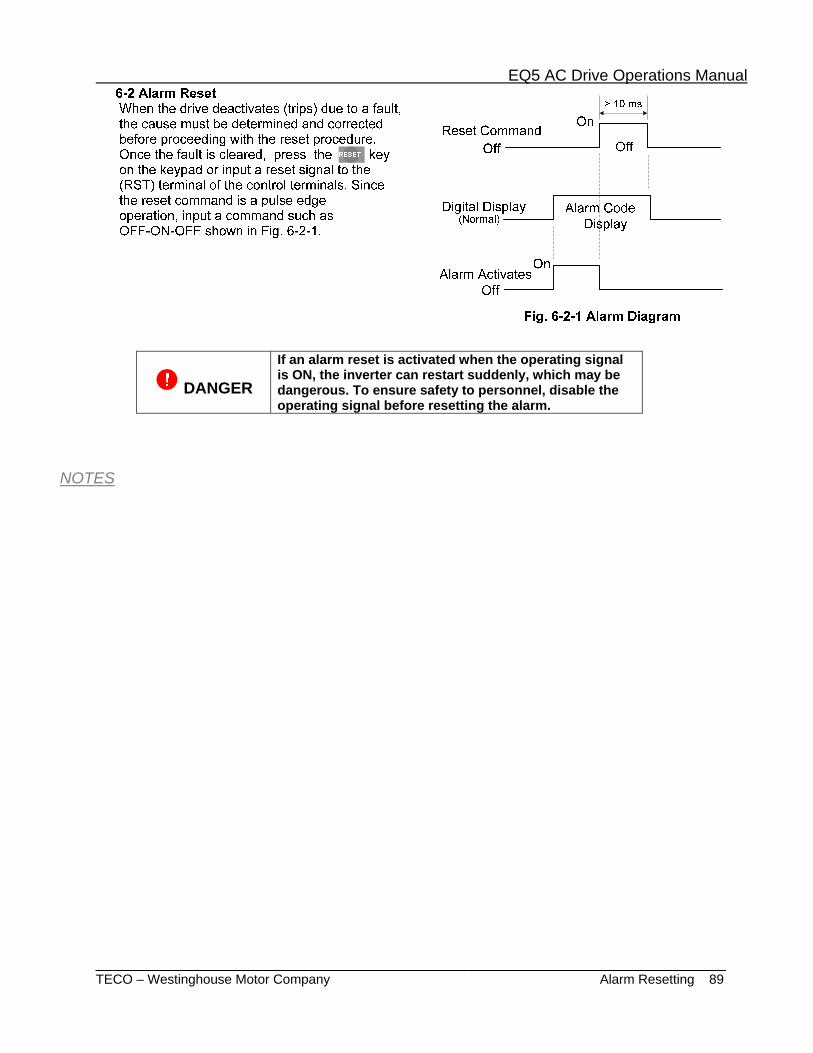
EQ5 AC Drive Operations Manual
_______________________________________________________________________ TECO – Westinghouse Motor Company Alarm Resetting 89
DANGER
If an alarm reset is activated when the operating signal is ON, the inverter can restart suddenly, which may be dangerous. To ensure safety to personnel, disable the operating signal before resetting the alarm.
NOTES

EQ5 AC Drive Operations Manual
______________________________________________________________________ TECO – Westinghouse Motor Company Trouble Shooting Chart 90
6-3.Trouble shooting
6-3-1 Protective function activation (1) Overcurrent
YES
NONO
NO
YES
NO
NO
NO
YES
YES
YES Are the motor connecting terminals (U, V, W) short-circuited or grounded?
Reduce the load or increase the inverter capacity. Is the load excessive?
Can the torque boostamount be reduced?
Remove the short-circuit and ground fault.
Prolong time settings.
Reduce the load or increase the inverter capacity.
Is the torque boostcorrect?
Reduce the torque boost. Is the acceleration time setting too short
compared with the load?
YES
Has the load changed suddenly?
NO
NO
NO
YES
NOCan the deceleration time setting be prolonged?
YES
NO
Reduce the load or increase the inverter capacity.
YES
Overcurrent during acceleration
OC1
Is the deceleration time setting too short compared
with the load?
Can the acceleration time setting be prolonged?
YES
Overcurrentduring deceleration
OC2
Overcurrentrunning at constant speed
OC3
NO
Faulty inverter or error due to noise.
Consult with TWMC.
The braking method requires inspection.
Contact TWMC.
(2) Ground fault
Note: The ground fault protective function is only available for inverters rated 40HP/CT, 50HP/VT and above.
(3) Fuse brown
Possible short-circuitwithin the inverter.Contact TWMC.
Fuse blownFUS
Ground fault EF
Remove the grounded part.
YES
Faulty inverter or error due to noise. Contact TWMC. NO
Is a part in the inverter output circuit (cable, motor) grounded?

EQ5 AC Drive Operations Manual
_______________________________________________________________________ TECO – Westinghouse Motor Company Trouble Shooting Chart 91
(4) Overvoltage
Overvoltageduring acceleration
OU1
Overvoltagerunning at constant speed
OU3
Overvoltageduring deceleration
OU2
Reduce the supply voltageto less than the specified
upper limit.NO Is the power supply voltage within the specified value?
Is start mode(H09) activated and its start-mode?
YES YES YES
NONONO
NONONO
YES
NO
NO
NO
NO
YES
Can the deceleration time be prolonged?
Reduce.
NO
Does OU alarm activatewhen acceleration
is completed?NO
YES
YES
Prolong.
NO
Can the accelerationtime be prolonged?
NO
NO
Can the moment of load inertia be reduced?NO
NO
YESIs the braking device or DC brake function in use?
YES
YES
YES YES YES
NO
Is restart mode after momentary power failure oroperation switching between line and inverter?
Does OU activated when the load is suddenly removed? YES
Consider usinga braking system
or DC brake function.
YES Restart time(H13) isset longer.
YES Check the motor and /orthe terminal(U, V, W)
is shorted or ground fault.
Does the main circuit DC link circuitvoltage exceed the protection level?
Faulty inverteror error due to noise.
Contact TWMC.
Inspect the braking method. Contact TWMC.
(5) Low voltage
NO
NO
YES
YES
Low voltageLU
Reset and restartoperation.
Replace the faulty partand repair the connection.
Is power transformercapacity adequate?
Has a (momentary) powerfailure occurred?
Faulty parts or looseconnection in the
power circuit?
NO
YES
Does LU activate whenthe circuit breaker ormagnetic contactor is
switched on?
Is there a load requiringa large starting currentwithin the same power
distribution group?
YES
NO
YES
Is the main circuit DC voltage(between P-N) higher than
the detection level specifiedin Section 6.1.1?
NONOYES
YES
Modify power distribution systemto satisfy the specified value.
The inverter may be faulty.Contact TWMC.
Is the power supplyvoltage within thespecified value?
Faulty of inverter controlcircuit or error due
to noise, etc.Contact TWMC.

EQ5 AC Drive Operations Manual
_______________________________________________________________________ TECO – Westinghouse Motor Company Trouble Shooting Chart 92
YES
YES
NO
Is PTC operating?Incorrect motor load or inadequate cooling. Check the motor side.
External thermal relay trippedOH2
Is PTC level H27 set correctly?
Is PTC MODE H26 enabled?
YES
NO
NO
Change to regular external circuit.
Is the external circuit (including constants) regular?
Set to correct value.
NO
YES
(7) External thermal relay tripped
YES
NO
Connect a thermal O/L relay externally.
Is the electronic thermal O/L relay setting correct? Set to the correct level
Is the load excessive?
Inverter unit overload OLU
Motor overload OL1, OL2
Do the characteristics of the electronic thermal O/L relay and motor overload match?
NO
NO
YES
YES
Reduce the load or increase inverter capacity
(8) Inverter unit overload and motor overload
NO
YES
NO
NO
Is the load excessive? Reduce the load.
Is the cooling fan rotating? Replace the cooling fan.
Check the temperature of the heatsink using the alarm information displayed on the keypad panel.
Remove obstacles.
Overtemperature at inside air OH3
Does the heatsink temperature indicate -10Ž or lower?
YES
YES
YES
YESIs the ambient temperature within the specification?
Arrange peripheral conditions to meet the specification.
Overheating at heatsink OH1
NO
NO
Is the cooling air passage blocked?
(6) Overtemperature at inside air and overheating at heatsink.
YES
Connect the alarm signal contact.
Is the alarm function of the external equipment operating correctly?
YES
Remove the cause of alarm function activation.
NO
NO
Is data input to the control terminals THR-X1 to X9? Are alarm signals from external equipment input to the terminals and the CM?
Faulty inverter or error due to noise, etc. Contact TWMC.
Faulty inverter or error due to noise, etc. Contact TWMC.
Faulty inverter or error due to noise, etc. Contact TWMC.
Faulty inverter or error due to noise, etc. Contact TWMC.
Faulty detection circuit on PCB. Contact TWMC.
NO
YES
YES (30HP/CT, 40HP/VT or less)
NO
YES
YES
NO
YES
NO NO
YES
YES
NO
NO
YES
NO NO
YES
Overtemperature at inside air OH3
Overheating at heatsink OH1
Is between the control terminals 13-11 closed?
Check the temperature of the heatsink using the alarm information displayed on the keypad panel.
Remove the short circuit.
Check the keypad panel display. Display limit or not? 30HP or less: 20 degrees C.
Is the cooling fan for mixing inside air rotating? (40HP/CT, 50HP/VT or more)
Is the peripheral temperature of the inverter –10 degrees C or less ?
Is between the control terminals 13-11 closed?
Faulty detection circuit on PCB. Contact TWMC
Make peripheral temperature of the inverter to meet the specification.
Is the load Reduce the load.
Replace the cooling fan.
Is the cooling fan rotating?
Replace the cooling fan for mixing inside air.
Is the cooling fan for mixing inside air rotating? (40HP/CT, 50HP/VT or more)
Remove obstacles. Is the cooling air passage blocked?
Faulty inverter or error due to noise, etc. Contract TWMC.
Is the ambient temperature within the specification ?
Arrange peripheral conditions to meet the specification.
(6) Overtemperature at inside air and overheating at heatsink.
YES (30HP/CT, 40HP/VT or less)
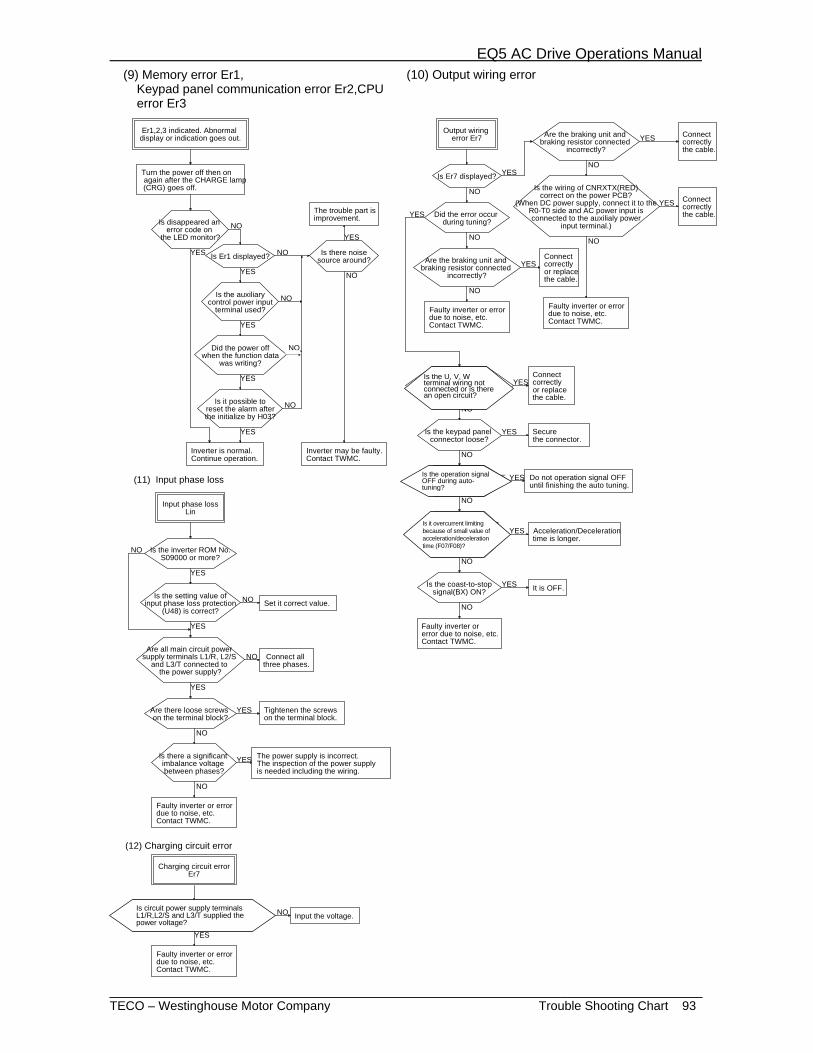
EQ5 AC Drive Operations Manual
_______________________________________________________________________ TECO – Westinghouse Motor Company Trouble Shooting Chart 93
(9) Memory error Er1, Keypad panel communication error Er2, CPU error Er3
Er1,2,3 indicated. Abnormal display or indication goes out.
(10) Output wiring error
Turn the power off then on again after the CHARGE lamp (CRG) goes off.
YES
Did the error occur during tuning?
NO
Is Er7 displayed?
YESConnect correctly or replace the cable.
Output wiring error Er7
NO
NO
Are the braking unit and braking resistor connected
incorrectly?
YES
NO
Is The U,V,W terminal wiring not connected
or is there an open circuit?
Connect correctly or replace the cable.
Is the keypad panel connector loose?
Secure the connector.
NO
YES
Is the operation signal OFFduring auto-tuing?
YES
NO
Is it overcurrent limitingbecause of small value ofaccelaration/deceleration
time(F07/F08)?
Is the coast-to-stopsignal(BX) ON?
YES
YES
Acceleration/Decelerationtime is longer.
It is OFF.
NO
NO
Is disappeared an error code on
the LED monitor?NO
YES
NO
YES
NO
YES
Is the auxiliarycontrol power input
terminal used?
YES
NO
NO
Is Er1 displayed?
Is it possible toreset the alarm afterthe initialize by H03?
YES
NO
The trouble part isimprovement.
Is there noisesource around?
Inverter is normal. Continue operation.
Input phase lossLin
NO
NO
NO
YES
YES
Is the setting value ofinput phase loss protection
(U48) is correct?
NO Connect all three phases.
YES
Is the inverter ROM No.S09000 or more?
YES Tightenen the screws on the terminal block.
Are there loose screws on the terminal block?
Is there a significant imbalance voltage between phases?
NO
YES
Set it correct value.
Is the wiring of CNRXTX(RED)correct on the power PCB?
(When DC power supply, connect it to theR0-T0 side and AC power input isconnected to the auxilialy power
input terminal.)
NO
NO
YES
YES Connect correctly the cable.
Are the braking unit and braking resistor connected
incorrectly?
Connect correctly the cable.
YES
(11) Input phase loss
YES
(12) Charging circuit error
Charging circuit errorEr7
Are all main circuit power supply terminals L1/R, L2/S
and L3/T connected to the power supply?
Is circuit power supply terminals L1/R, L2/S and L3/T supplied the power voltage?
NO Input the voltage.
YES
Did the power offwhen the function data
was writing?
Inverter may be faulty. Contact TWMC.
Faulty inverter or error due to noise, etc. Contact TWMC.
Faulty inverter or error due to noise, etc. Contact TWMC.
The power supply is incorrect.The inspection of the power supplyis needed including the wiring.
Faulty inverter or error due to noise, etc. Contact TWMC.
Faulty inverter or error due to noise, etc. Contact TWMC.
Do not operation signal OFFuntil finishing the auto tuning.
Faulty inverter or error due to noise, etc. Contact TWMC.
Is the U, V, W terminal wiring not connected or is there an open circuit?
Is the operation signal OFF during auto-tuning?
Is it overcurrent limiting because of small value of acceleration/deceleration time (F07/F08)?
(9) Memory error Er1, Keypad panel communication error Er2,CPU error Er3
(10) Output wiring error
Is circuit power supply terminals L1/R,L2/S and L3/T supplied the power voltage?
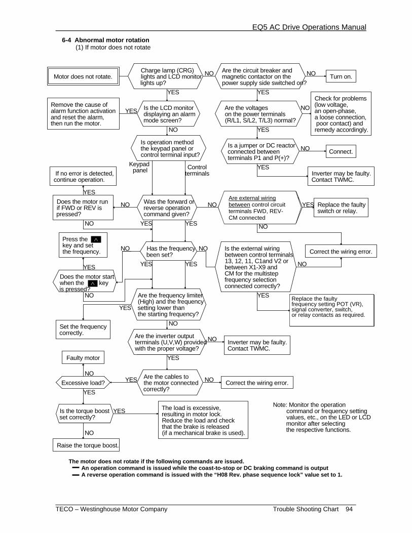
EQ5 AC Drive Operations Manual
_______________________________________________________________________ TECO – Westinghouse Motor Company Trouble Shooting Chart 94
6-4 Abnormal motor rotation (1) If motor does not rotate
YES
NO
YES
YES
NO
NO
YES
NO
YES
Motor does not rotate.Charge lamp (CRG) lights and LCD monitor lights up?
Are the circuit breaker and magnetic contactor on the power supply side switched on?
Turn on.
Is the LCD monitor displaying an alarm mode screen?
Is operation method the keypad panel or control terminal input?
Is a jumper or DC reactor connected between terminals P1 and P(+)?
Connect.
If no error is detected, continue operation.
Keypad panel Control
terminals
Does the motor run if FWD or REV is pressed?
Was the forward or reverse operation command given?
Replace the faulty switch or relay.
Has the frequency been set? Correct the wiring error.
Set the frequency correctly. Are the inverter output
terminals (U,V,W) provided with the proper voltage?
Faulty motor
Excessive load? Correct the wiring error.
Is the torque boost set correctly?
The load is excessive, resulting in motor lock. Reduce the load and check that the brake is released (if a mechanical brake is used).
NO NO
Remove the cause of alarm function activation and reset the alarm, then run the motor.
YES
YES
Are the voltages on the power terminals (R/L1, S/L2, T/L3) normal?
NO
YES
YES
NO
NO
YES
NO
YES
YES
NO
NO
YES NO
NO
Replace the faulty frequency setting POT (VR), signal converter, switch, or relay contacts as required.
NOCheck for problems (low voltage, an open-phase, a loose connection, poor contact) and remedy accordingly.
Are the frequency limiter (High) and the frequency setting lower than the starting frequency?
YES
Are the cables to the motor connected correctly?
YES
NO
NO
YESNO
YES
Raise the torque boost.
YESNote: Monitor the operation command or frequency setting values, etc., on the LED or LCD monitor after selecting the respective functions.
Is the external wiring between control terminals 13, 12, 11, C1and V2 orbetween X1-X9 and CM for the multistep frequency selection connected correctly?
Inverter may be faulty. Contact TWMC.
Press the key and set the frequency.
Does the motor start when the key is pressed?
Are external wiring between control circuit terminals FWD, REV -CMconnected correctly?
Inverter may be faulty. Contact TWMC.
The motor does not rotate if the following commands are issued. An operation command is issued while the coast-to-stop or DC braking command is output A reverse operation command is issued with the “H08 Rev. phase sequence lock” value set to 1.
∧
Are external wiring between control circuit terminals FWD, REV-CM connected
Replace the faulty frequency setting POT (VR), signal converter, switch, or relay contacts as required.
∧
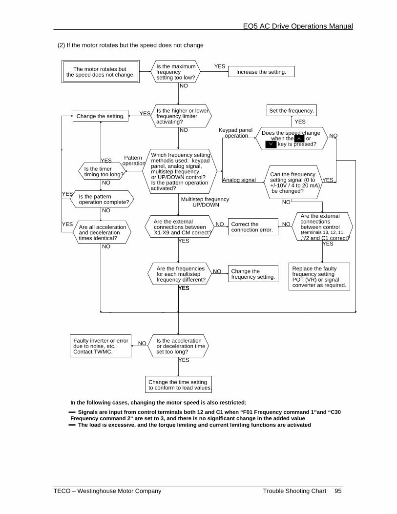
EQ5 AC Drive Operations Manual
_______________________________________________________________________ TECO – Westinghouse Motor Company Trouble Shooting Chart 95
(2) If the motor rotates but the speed does not change
NO
YES
NO
NO
YESNO
YESYES
Change the setting.
Is the pattern operation complete?
Are all acceleration and deceleration times identical?
Are the frequencies for each multistep frequency different?
Change the frequency setting.
Is the acceleration or deceleration time set too long?
Change the time setting to conform to load values.
The motor rotates but the speed does not change.
Is the maximum frequency setting too low?
NO
YES
Is the timer timing too long?
YES
NO
Which frequency setting methodis used: keypad panel, analog signal, multistep frequency, or UP/DOWN control? Is the pattern operation activated?
Pattern operation
NO
Analog signal
Keypad panel operation
YES
NO
Correct the connection error.
YES
NO
NO
Is the higher or lower frequency limiter activating?
Does the speed change when the or
key is pressed?
YES
Multistep frequency UP/DOWN
YES
Replace the faulty frequency setting POT (VR) or signal converter as required.
NOAre the external connections between control terminals 13, 12,11,V2 and C1 correct?
Are the external connections between X1-X9 and CM correct?
Faulty inverter or error due to noise, etc. Contact TWMC.
Increase the setting.YES
YES
Set the frequency.
Can the frequency setting signal (0 to +/-10V / 4 to 20 mA) be changed?
YES
∨∧
In the following cases, changing the motor speed is also restricted:
Signals are input from control terminals both 12 and C1 when “F01 Frequency command 1”and “C30 Frequency command 2” are set to 3, and there is no significant change in the added value The load is excessive, and the torque limiting and current limiting functions are activated
terminals 13, 12, 11,
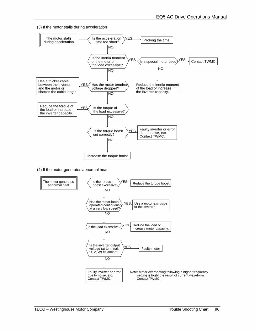
EQ5 AC Drive Operations Manual
_______________________________________________________________________ TECO – Westinghouse Motor Company Trouble Shooting Chart 96
(3) If the motor stalls during acceleration
(4) If the motor generates abnormal heat
NO
YES
YES
Is the torque boost excessive? Reduce the torque boost.
Has the motor been operated continuously at a very low speed?
Use a motor exclusive to the inverter.
Is the load excessive? Reduce the load or increase motor capacity.
Is the inverter output voltage (at terminals U, V, W) balanced?
Faulty motor
YES
NO
YES
NO
NO
The motor generates abnormal heat.
Faulty inverter or error due to noise, etc. Contact TWMC.
Note: Motor overheating following a higher frequency setting is likely the result of current waveform. Contact TWMC.
YES
YES
YESIs the inertia moment of the motor or the load excessive?
Is a special motor used?
Has the motor terminal voltage dropped?
Reduce the inertia moment of the load or increase the inverter capacity.
Is the torque of the load excessive?
Is the torque boost set correctly?
Increase the torque boost.
The motor stalls during acceleration. Prolong the time.
NO
Is the acceleration time too short?
YES
NO NO
NO
NO
NO
Use a thicker cable between the inverter and the motor or shorten the cable length.
YES
Reduce the torque of the load or increase the inverter capacity.
YES
Faulty inverter or error due to noise, etc. Contact TWMC.
Contact TWMC.

_______________________________________________________________________ TECO – Westinghouse Motor Company Maintenance & Inspection 97
7. Maintenance and Inspection It is recommended that daily and periodic inspections be carried out to insure trouble-free operation and long-term reliability. The following are recommendations for conducting these inspections.
7-1 Daily Inspection During operation, a visual inspection for abnormal operation can be completed externally without removing the covers.
The inspections should cover the following: (1) The performance is as expected and is within specifications. (2) The environment conforms to the drive specifications. (3) The digital operator is functioning normally. (4) There are no abnormal sounds, vibrations, or odors. (5) There are no indications of overheating or discoloration.
7-2 Periodic Inspections Periodic inspections are carried out after stopping drive operations, disconnecting the power source, and removing the protective cover(s).
DANGER
• Because the large capacitors in the main DC circuit retain lethal voltage levels after power is disconnected and take time to discharge, wait at least five minutes after turning off the power supply for inverter rated at 30HP/CT, 40HP/VT or less, and ten minutes for inverter rated at 40HP/CT, 50HP/VT or more. (Check that the charge lamp (CRG) is off, and that the voltage is 25V DC or less between terminals P(+) and N(-). Otherwise, electric shock or injury may result.
• Only authorized personnel should carry out maintenance and component replacement operations. (Remove metal jewelry such as watches and rings and use insulated tools.)
• Never modify the inverter. Otherwise, electric shock or injury may result. Table 7-2-1 Periodic Inspection List
Area to Check Items to Check How to Inspect Evaluation Criteria
Environment
1) Check the ambient temperature, humidity, Vibration and atmosphere (dust, gas, oil mist, water drops).
2) Is the area surrounding the equipment free of foreign objects?
1) Conduct visual inspection and use the appropriate equipment.
2) Visual inspection.
1)Results comply with specifications. 2) The area is clear.
Digital operator
1) Is the display hard to read? 2) Are the characters complete?
1) Visual inspection. 2) Visual inspection.
1) The display can be read. 2) Characters are
complete.
Structure (frame & cover)
1) Is there abnormal sounds or vibration? 2) Are fasteners loose? 3) Is there deformation or damage? 4) Is there discoloration as a result of
overheating? 5) Are there stains or accumulated dust?
1) Visual and aural Inspection.
2) Tighten. 3) Visual inspection. 4) “ 5) “
1) No abnormalities 2) “ 3) “ 4) “ 5) “
Mai
n ci
rcui
t Common
1) Are there loose or missing fasteners? 2) Is there deformation, cracks, damage, and
discoloration due to overheating or deterioration in the equipment and insulation?
3) Are there stains and accumulated dust?
1) Tighten. 2) Visual inspection. 3) “
1) No abnormalities 2) No abnormalities
Note: Discoloration of the bus bar does 3) not indicate a problem.
Conductor and wire
1) Is there discoloration or distortion of a conductor(s) due to overheating?
2) Are there cracks, crazing or discoloration of the cable sheath?
1) Visual inspection. 2) “
1) No abnormalities 2) “
Cont.

_______________________________________________________________________ TECO – Westinghouse Motor Company Maintenance & Inspection 98
Mai
n ci
rcui
t
Terminal block Is there damage? Visual inspection No abnormalities
Main DC Capacitor(s)
1) Is there electrolyte leakage, discoloration, crazing, or swelling of the case?
2) Is the safety valve not protruding or are valves protruding too far?
3) Measure the capacitance if necessary.
1) Visual inspection 2) Visual inspection 3) * Estimate life
expectancy from maintenance information and from measurements using capacitance measuring equipment.
1) No abnormalities 2) “ 3) Capacitance ≧ initial value x 0.85
Resistor
1) Is there unusual odor or damage to the insulation by overheating?
2) Is there an open circuit?
1) Visual and olfactory inspection.
2) Conduct a visual Inspection or use a multimeter by opening the connection on one side.
1) No abnormalities 2) Less than ±10% of
the indicated resistance value.
Transformer and reactor
Is there abnormal buzzing or an abnormal odor?
Auditory, olfactory, and visual inspection
No abnormalities
Magnetic contactor and relay
1) Is there chattering during operation? 2) Are the contacts pitted or burnt?
1) Auditory inspection 2) Visual inspection
1) No abnormalities 2) “
Con
trol c
ircui
t
Control PC board and connector
1) Are there any loose screws or connectors? 2) Is there an unusual odor or discoloration? 3) Are there cracks, damage, deformation, or
rust? 4) Is there electrolyte leakage or damage to
any of the capacitors?
1) Tighten. 2) Visual and olfactory
inspection 3) Visual inspection 4) * Estimate life
expectancy by visual inspection and maintenance information.
1) No abnormalities 2) “ 3) “ 4) “
Coo
ling
syst
em
Cooling fan
1) Is there any abnormal sound or vibration? 2) Are any fasteners loose? 3) Is there discoloration due to overheating?
1) Auditory and visual inspection.
2) Tighten. 3) Visual inspection 4) * Estimate life
expectancy by maintenance information
1) The fan must rotate smoothly.
2) No abnormalities 3) “
Ventilation Is there foreign matter on the heat sink or intake and exhaust ports?
Visual inspection No abnormalities
Note: If equipment is stained, wipe with a clean cloth. Vacuum the dust. * The maintenance information is stored in the inverter digital operator and indicates the electrostatic capacitance of the main DC circuit capacitors and the life expectancy of the electrolytic capacitors on the control PC board and of the cooling fans. Use this data as the basis to estimate the life expectancy of parts.
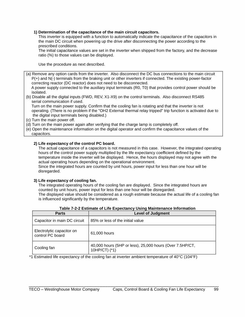
_______________________________________________________________________ TECO – Westinghouse Motor Company Caps, Control Board & Cooling Fan Life Expectancy 99
1) Determination of the capacitance of the main circuit capacitors.
This inverter is equipped with a function to automatically indicate the capacitance of the capacitors in the main DC circuit when powering up the drive after disconnecting the power according to the prescribed conditions. The initial capacitance values are set in the inverter when shipped from the factory, and the decrease ratio (%) to those values can be displayed. Use the procedure as next described.
(a) Remove any option cards from the inverter. Also disconnect the DC bus connections to the main circuit P(+) and N(-) terminals from the braking unit or other inverters if connected. The existing power-factor correcting reactor (DC reactor) does not need to be disconnected. A power supply connected to the auxiliary input terminals (R0, T0) that provides control power should be isolated. (b) Disable all the digital inputs (FWD, REV, X1-X9) on the control terminals. Also disconnect RS485 serial communication if used. Turn on the main power supply. Confirm that the cooling fan is rotating and that the inverter is not operating. (There is no problem if the "OH2 External thermal relay tripped" trip function is activated due to the digital input terminals being disabled.) (c) Turn the main power off. (d) Turn on the main power again after verifying that the charge lamp is completely off. (e) Open the maintenance information on the digital operator and confirm the capacitance values of the capacitors.
2) Life expectancy of the control PC board. The actual capacitance of a capacitors is not measured in this case. However, the integrated operating hours of the control power supply multiplied by the life expectancy coefficient defined by the temperature inside the inverter will be displayed. Hence, the hours displayed may not agree with the actual operating hours depending on the operational environment.
Since the integrated hours are counted by unit hours, power input for less than one hour will be disregarded.
3) Life expectancy of cooling fan. The integrated operating hours of the cooling fan are displayed. Since the integrated hours are counted by unit hours, power input for less than one hour will be disregarded. The displayed value should be considered as a rough estimate because the actual life of a cooling fan is influenced significantly by the temperature.
Table 7-2-2 Estimate of Life Expectancy Using Maintenance Information Parts Level of Judgment
Capacitor in main DC circuit 85% or less of the initial value
Electrolytic capacitor on control PC board 61,000 hours
Cooling fan 40,000 hours (5HP or less), 25,000 hours (Over 7.5HP/CT, 10HP/CT) (*1)
*1 Estimated life expectancy of the cooling fan at inverter ambient temperature of 40°C (104°F)
_______________________________________________________________________ TECO – Westinghouse Motor Company Inspection Notes & Records 100
Inspection Notes and Records
DATE ITEM ________________________________________________________________________________
EQ5 AC Drive Operations Manual
_______________________________________________________________________ TECO – Westinghouse Motor Company Main Circuit Voltage, Current & Power Measurements 101
7-3 Main Circuit Voltage, Current, and Power Measurements. When making main circuit voltage and current measurements, the resulting values depend on the type of meter used due to the harmonic component included in the voltage and current of the main circuit power (input) and the output (motor) side of the inverter. When measuring with a meter for commercial power frequency, use the meters shown in Table 7-3-1. The power-factor cannot be measured directly using power-factor meters commercially available at present on the market, which measure the phase difference between voltage and current. When power-factors must be measured, measure the power, voltage, and current on both the input side and output side, then calculate the power-factor using the following formula:
[%]][][
][ 0 0 1 At n e r r u C Ve g a t l o V 3
Wr e w o P r o tc a f r e w o P ×××
=−
Table 7-3-1 Meters Used for measuring Main Circuit Values
Item
Input (power supply) Side Output (motor) Side DC Link Circuit Voltage (P(+) - N(-))
Voltage Current*
Voltage Current
Meter name
Ammeter A R,S,T
Voltmeter V R,S,T
Powermeter W R,S,T
AmmeterA U,V,W
Voltmeter V U,V,W
Powermeter W U,V,W
DC voltmeter V
Meter type
Moving-iron type
Rectifier or moving-iron type
Digital power meter
Moving-iron type
Rectifier type
Digital power meter
Moving-coil type
Symbol
Note: When measuring the output voltage using a rectifier type meter, an error may occur. Use a digital AC power meter to ensure accuracy.
Meter Placement Diagram

EQ5 AC Drive Operations Manual
______________________________________________________________________ TECO – Westinghouse Motor Company Insulation Testing &Parts Replacement 102
7- 4 Insulation Test It is not necessary to do an insulation test on the inverter as this was completed at the factory. If an insulation test with a megger test must be completed, then proceed as described below as an incorrect testing method may result in product damage. If a dielectric strength test must be completed, the specifications for the test must be followed as Improper testing may result in damage to the inverter. Please contact your local distributor or nearest TWMC sales office for further guidance.
(1) Megger test for the main power circuit. a - Use a 500V DC type megger and isolate the main power before commencing measurement. b - If the test voltage is connected to the control circuit, remove all connection cables to the control circuit. c - Connect the main circuit terminals together using common cables as shown in Fig. 7-4-1. d - Perform the megger test only between the common cables connected to the main circuit and the ground (terminal G). e - A megger indicating a reading of 5MΩ or more is normal. (This is the value measured with only the inverter connected.)
Fig. 7-4-1 Main Circuit Insulation Test (2) Insulation test in the control circuit.
A megger test and a dielectric strength test must not be performed on the control circuit or damage will result. To test the control circuit, use a high resistance range multimeter and proceed as follows.
a - Remove all external cables from the control circuit terminals. b - Conduct a continuity test between the isolated control circuit grounds. A result of 1MΩ or more is normal.
(3) Exterior main circuit and sequence control circuit. Remove all cables from inverter terminals to ensure the test voltage is not applied to the inverter.
7-5 Parts Replacement The life expectancy of a part depends on the type of part, the environment, and usage
conditions. Parts should be replaced as shown in Table 7-5-1 Parts Replacement.
Table 7-5-1 Parts Replacement
Part Name Standard Period for Replacement Comments
Cooling fan 3 years Exchange for a new part.
Smoothing capacitor 5 years Exchange for a new part (determine after checking).
Electrolytic capacitor on the PC board 7 years
Exchange for a new PC board (determine after checking).
Fuse 10 years Exchange for a new part. Other parts - Determine after checking.
EQ5 AC Drive Operations Manual
________________________________________________________________________ TECO – Westinghouse Motor Company Damaged Product Inquiries & Warranty 103
7-6 Inquiries About Damaged Products If there is damage, a fault in the product, or questions concerning the product, contact your local distributor or nearest TWMC sales office with the following information:
a - Inverter type (Model No.) b - Serial No. (equipment serial number) c - Purchase date d - Problem details (e.g., damaged part, extent of damage, questions, status of fault)
7-7 Warranty All Low Voltage Motor Control Products, such as Solid State Starters and Inverters, (“products”) sold by TECO-Westinghouse Motors Company (“TWMC”), are warranted to be free from defects in material and workmanship for a period of 36` months from the date of shipment. A warranty of 36 months from the date of manufacture is applicable when a TWMC Low Voltage Motor Control Product and a TWMC Inverter Duty motor (per NEMA MG1-31.4.2.2) are purchased together.
This warranty is conditioned upon the installation, operation, and maintenance of the products in accordance with TWMC’s recommendations or standard industry practice, and that the products have at all times been operated or used under the normal operating conditions for which they were designed. This warranty will not be applicable to products that have been altered without prior written permission from TWMC.
TWMC shall, at its sole option and expense, repair or replace, F.O.B. warehouse or TWMC designated service center, any such products, which are defective within the warranty period. In the event of warranty claims, TWMC must be notified promptly following any product failure. The product shall be sent to a TWMC authorized service center for diagnosis of the cause of failure. TWMC will not be responsible for any repair that has been performed without prior written permission from TWMC.
The repair or replacement of defective material and workmanship shall constitute complete fulfillment of TWMC’s warranty liability, whether the warranty claims are based on contract, tort (including negligence and strict liability), or otherwise. THERE ARE NO OTHER WARRANTIES, EXPRESS OR IMPLIED, INCLUDING ANY IMPLIED WARRANTY OF MERCHANTABILITY AND FITNESS FOR A PARTICULAR PURPOSE, AND ALL WARRANTIES ARISING FROM COURSE OF DEALING AND USAGE OF TRADE. UNDER NO CIRCUMSTANCES, SHALL TWMC BE LIABLE FOR ANY SPECIAL, INDIRECT, INCIDENTAL OR CONSEQUENTIAL DAMAGES, INCLUDING FREIGHT.
Warranty Return Procedure The Product must be returned prepaid to TECO-Westinghouse Motor Company factory. A completed Return Material Authorization (RMA) form with an assigned RMA number must be included in the shipment. Contact the nearest TECO-Westinghouse location or Factory directly for RMA forms.
NOTES
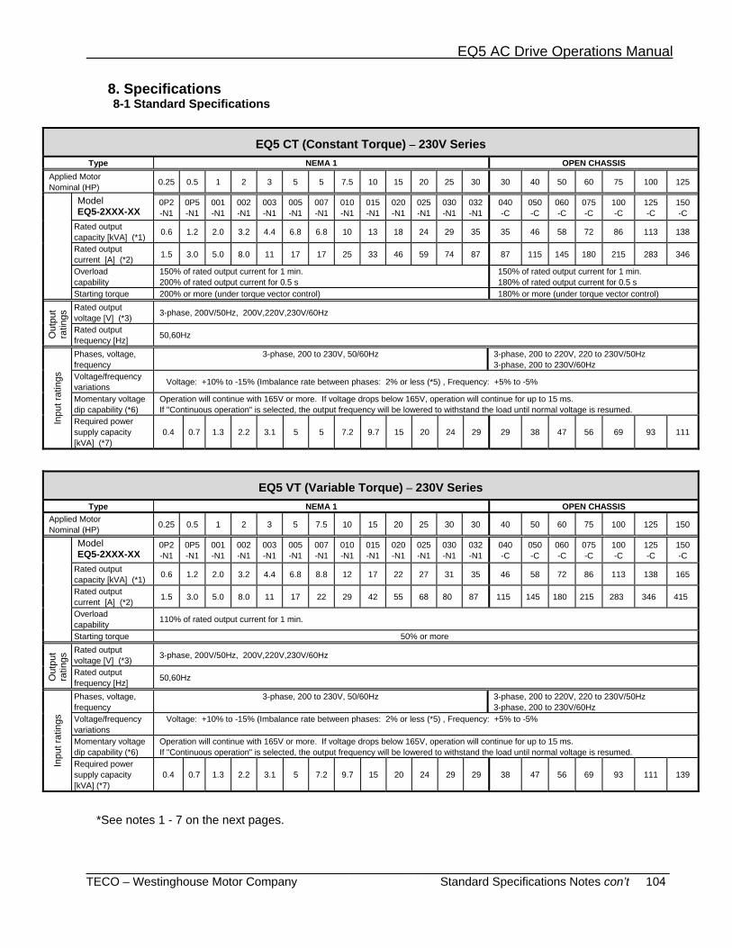
EQ5 AC Drive Operations Manual
_________________________________________________________________________ TECO – Westinghouse Motor Company Standard Specifications Notes con’t 104
8. Specifications 8-1 Standard Specifications
EQ5 CT (Constant Torque) – 230V Series Type NEMA 1 OPEN CHASSIS
Applied Motor Nominal (HP) 0.25 0.5 1 2 3 5 5 7.5 10 15 20 25 30 30 40 50 60 75 100 125
Model EQ5-2XXX-XX
0P2 -N1
0P5 -N1
001 -N1
002 -N1
003 -N1
005 -N1
007 -N1
010 -N1
015 -N1
020 -N1
025 -N1
030 -N1
032 -N1
040 -C
050 -C
060 -C
075 -C
100 -C
125 -C
150 -C
Rated output capacity [kVA] (*1) 0.6 1.2 2.0 3.2 4.4 6.8 6.8 10 13 18 24 29 35 35 46 58 72 86 113 138
Rated output current [A] (*2) 1.5 3.0 5.0 8.0 11 17 17 25 33 46 59 74 87 87 115 145 180 215 283 346
Overload capability
150% of rated output current for 1 min. 200% of rated output current for 0.5 s
150% of rated output current for 1 min. 180% of rated output current for 0.5 s
Starting torque 200% or more (under torque vector control) 180% or more (under torque vector control)
Out
put
ratin
gs Rated output
voltage [V] (*3) 3-phase, 200V/50Hz, 200V,220V,230V/60Hz
Rated output frequency [Hz] 50,60Hz
Inpu
t rat
ings
Phases, voltage, frequency
3-phase, 200 to 230V, 50/60Hz 3-phase, 200 to 220V, 220 to 230V/50Hz 3-phase, 200 to 230V/60Hz
Voltage/frequency variations Voltage: +10% to -15% (Imbalance rate between phases: 2% or less (*5) , Frequency: +5% to -5%
Momentary voltage dip capability (*6)
Operation will continue with 165V or more. If voltage drops below 165V, operation will continue for up to 15 ms. If "Continuous operation" is selected, the output frequency will be lowered to withstand the load until normal voltage is resumed.
Required power supply capacity [kVA] (*7)
0.4 0.7 1.3 2.2 3.1 5
5 7.2 9.7 15 20 24
29 29 38 47 56 69 93 111
EQ5 VT (Variable Torque) – 230V Series Type NEMA 1 OPEN CHASSIS
Applied Motor Nominal (HP) 0.25 0.5 1 2 3 5 7.5 10 15 20 25 30 30 40 50 60 75 100 125 150
Model EQ5-2XXX-XX
0P2 -N1
0P5 -N1
001 -N1
002 -N1
003 -N1
005 -N1
007 -N1
010 -N1
015 -N1
020 -N1
025 -N1
030 -N1
032 -N1
040 -C
050 -C
060 -C
075 -C
100 -C
125 -C
150 -C
Rated output capacity [kVA] (*1) 0.6 1.2 2.0 3.2 4.4 6.8 8.8 12 17 22 27 31 35 46 58 72 86 113 138 165
Rated output current [A] (*2) 1.5 3.0 5.0 8.0 11 17 22 29 42 55 68 80 87 115 145 180 215 283 346 415
Overload capability 110% of rated output current for 1 min.
Starting torque 50% or more
Out
put
ratin
gs Rated output
voltage [V] (*3) 3-phase, 200V/50Hz, 200V,220V,230V/60Hz
Rated output frequency [Hz] 50,60Hz
Inpu
t rat
ings
Phases, voltage, frequency
3-phase, 200 to 230V, 50/60Hz 3-phase, 200 to 220V, 220 to 230V/50Hz 3-phase, 200 to 230V/60Hz
Voltage/frequency variations
Voltage: +10% to -15% (Imbalance rate between phases: 2% or less (*5) , Frequency: +5% to -5%
Momentary voltage dip capability (*6)
Operation will continue with 165V or more. If voltage drops below 165V, operation will continue for up to 15 ms. If "Continuous operation" is selected, the output frequency will be lowered to withstand the load until normal voltage is resumed.
Required power supply capacity [kVA] (*7)
0.4 0.7 1.3 2.2 3.1 5 7.2 9.7 15 20 24
29 29 38 47 56 69 93 111 139
*See notes 1 - 7 on the next pages.

EQ5 AC Drive Operations Manual
_________________________________________________________________________ TECO – Westinghouse Motor Company Standard Specifications Notes con’t 105
EQ5 CT (Constant Torque) – 460V Series
Type Nema 1 Open Chassis Applied Motor Nominal (HP) 0.5 1 2 3 5 5 7.5 10 15 20 25 30 30 40 50 60 75 100 125 150 200 250 300 350 350 400 450 500 600
Type EQ5-4XXX-XX
0P5 -N1
001- -N1
002--N1
003 -N1
005 -N1
005 -N1
010 -N1
015 -N1
020-N1
025-N1
030-N1
032-N1
040-C
050-C
060-C
075-C
100-C
125-C
150-C
200-C
250 -C
300 -C
350 -C
400 -C
450-C
500-C
600-C
700-C
800-C
Rated capacity [kVA] (*1) 1.2 2.0 2.9 4.4 7.2 7.2 10 14 19 24 31 36 36 48 60 73 89 120 140 167 202 242 300 331 331 414 466 518 590
Rated output current [A] (*2) 1.5 2.5 3.7 5.5 9 9 13 18 24 30 39 45 45 60 75 91 112 150 176 210 253 304 377 415 415 520 585 650 740
Overload capability
150% of rated output current for 1 min. 200% of rated output current for 0.5 s
150% of rated output current for 1 min. 180% of rated output current for 0.5 s
Starting torque 200% or more (under torque vector control) 180% or more (under torque vector control)
Out
put
ratin
gs Rated output
Voltage [V] (*3) 3-phase, 380V, 400V, 415V(440V)/50Hz, 380V, 400V, 440V, 460V/60Hz
Rated output frequency [Hz] 50,60Hz
Inpu
t rat
ings
Phases, voltage, frequency 3-phase,380 to 480V,50/60Hz 3-phase, 380 to 440V/50Hz (*5)
3-phase, 380 to 480V/60Hz Voltage/frequency variations Voltage: +10% to -15% (Imbalance rate between phases: 2% or less (*5) , Frequency: +5% to -5%
Momentary voltage dip capability (*6)
Operation will continue with 310V or more. If voltage drops below 310V, operation will continue for up to 15 ms. If "Continuous operation" is selected, the output frequency will be lowered to withstand the load until normal voltage is resumed.
Required power supply capacity [kVA] (*7)
0.7 1.2 2.2 3.1 5.0 5.0 7.2 9.7 15 20 24 29 29 38 47 57 70 93 111 136 161 196 244 267 267 341 383 433 488
EQ5 VT (Variable Torque) – 460V Series
Type Nema 1 Open Chassis Applied Motor Nominal (HP) 0.5 1 2 3 5 7.5 10 15 20 25 30 30 40 50 60 75 100 125 150 200 250 300 350 400 450 500 600 700 800
Type EQ5-4XXX-XX
0P5 -N1
001- -N1
002--N1
003 -N1
005 -N1
005 -N1
010 -N1
015 -N1
020-N1
025-N1
030-N1
032-N1
040-C
050-C
060-C
075-C
100-C
125-C
150-C
200-C
250 -C
300 -C
350 -C
400 -C
450-C
500-C
600-C
700-C
800-C
Rated capacity [kVA] (*1) 1.2 2.0 2.9 4.4 7.2 10 13 18 24 29 35 36 48 60 73 89 120 140 167 202 242 300 331 386 414 518 590 669 765
Rated output current [A] (*2) 1.5 2.5 3.7 5.5 9 12.5 16.5 23 30 37 44 45 60 75 91 112 150 176 210 253 304 377 415 485 520 650 740 840 960
Overload capability 110% of rated output current for 1 min.
Starting torque 50% or more
Out
put
ratin
gs Rated output
voltage [V] (*3) 3-phase, 380V, 400V, 415V(440V)/50Hz, 380V, 400V, 440V, 460V/60Hz
Rated output frequency [Hz] 50,60Hz
Inpu
t rat
ings
Phases, voltage, frequency
3-phase,380 to 480V,50/60Hz 3-phase, 380 to 440V/50Hz (*4) 3-phase, 380 to 480V/60Hz
Voltage/frequency variations Voltage: +10% to -15% (Imbalance rate between phases: 2% or less (*5) , Frequency: +5% to -5%
Momentary voltage dip capability (*6)
Operation will continue with 310V or more. If voltage drops below 310V, operation will continue for up to 15 ms. If "Continuous operation" is selected, the output frequency will be lowered to withstand the load until normal voltage is resumed.
Required power Supply capacity [kVA] (*7)
0.7 1.2 2.2 3.1 5.0 7.2 9.7 15 20 24 29 29 38 47 57 70 93 111 136 161 196 244 267 341 383 433 488 549 610
(*1) Indicated capacities are at the rated output voltage 230V for the 230V series and 460V for the 460V series. The rated capacity will be lowered if the
supply voltage is lower. (*2) In the case of a low impedance load, such as a high-frequency motor, the current may drop below the rated value. (*3) The output voltage cannot exceed the input supply voltage.
Cont.
EQ5 AC Drive Operations Manual
_________________________________________________________________________ TECO – Westinghouse Motor Company Standard Specifications Notes con’t 106
(*4) The taps within the inverter must be changed for an input power supply rated at 380 to 398V/50 Hz or 380 to 430V/60 Hz. (*5) If the imbalance between phases exceeds 2%, use a power-factor correcting DC reactor (DCR).
( Max. Voltage [V] - Min. Voltage [V] ) Imbalance rate between phases [%] = x 67[%]
3-phase average voltage [V] (*6) The test was conducted under the standard load conditions stipulated by the JEMA committee (at the load equivalent to 85% of the
nominal applied motor HP). (*7) Indicates the values required when using a power-factor correcting DC reactor (DCR) with a loaded nominal applied motor. (optional for inverters of
75HP/CT, 100HP/VT or less)
NOTES
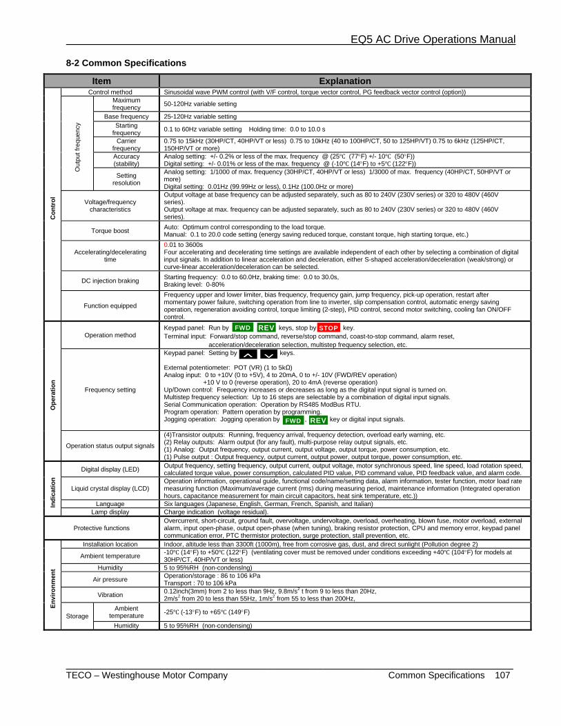
EQ5 AC Drive Operations Manual
_________________________________________________________________________ TECO – Westinghouse Motor Company Common Specifications 107
8-2 Common Specifications
Item Explanation
Con
trol
Control method Sinusoidal wave PWM control (with V/F control, torque vector control, PG feedback vector control (option))
Out
put f
requ
ency
Maximum frequency 50-120Hz variable setting
Base frequency 25-120Hz variable setting Starting
frequency 0.1 to 60Hz variable setting Holding time: 0.0 to 10.0 s
Carrier frequency
0.75 to 15kHz (30HP/CT, 40HP/VT or less) 0.75 to 10kHz (40 to 100HP/CT, 50 to 125HP/VT) 0.75 to 6kHz (125HP/CT, 150HP/VT or more)
Accuracy (stability)
Analog setting: +/- 0.2% or less of the max. frequency @ (25 (77°F) +/- 10 (50°F)) Digital setting: +/- 0.01% or less of the max. frequency @ (-10 (14°F) to +5 (122°F))
Setting resolution
Analog setting: 1/1000 of max. frequency (30HP/CT, 40HP/VT or less) 1/3000 of max. frequency (40HP/CT, 50HP/VT or more) Digital setting: 0.01Hz (99.99Hz or less), 0.1Hz (100.0Hz or more)
Voltage/frequency characteristics
Output voltage at base frequency can be adjusted separately, such as 80 to 240V (230V series) or 320 to 480V (460V series). Output voltage at max. frequency can be adjusted separately, such as 80 to 240V (230V series) or 320 to 480V (460V series).
Torque boost Auto: Optimum control corresponding to the load torque. Manual: 0.1 to 20.0 code setting (energy saving reduced torque, constant torque, high starting torque, etc.)
Accelerating/decelerating time
0.01 to 3600s Four accelerating and decelerating time settings are available independent of each other by selecting a combination of digital input signals. In addition to linear acceleration and deceleration, either S-shaped acceleration/deceleration (weak/strong) or curve-linear acceleration/deceleration can be selected.
DC injection braking Starting frequency: 0.0 to 60.0Hz, braking time: 0.0 to 30.0s, Braking level: 0-80%
Function equipped
Frequency upper and lower limiter, bias frequency, frequency gain, jump frequency, pick-up operation, restart after momentary power failure, switching operation from line to inverter, slip compensation control, automatic energy saving operation, regeneration avoiding control, torque limiting (2-step), PID control, second motor switching, cooling fan ON/OFF control.
Ope
ratio
n
Operation method Keypad panel: Run by , keys, stop by key. Terminal input: Forward/stop command, reverse/stop command, coast-to-stop command, alarm reset, acceleration/deceleration selection, multistep frequency selection, etc.
Frequency setting
Keypad panel: Setting by , keys. External potentiometer: POT (VR) (1 to 5kΩ) Analog input: 0 to +10V (0 to +5V), 4 to 20mA, 0 to +/- 10V (FWD/REV operation) +10 V to 0 (reverse operation), 20 to 4mA (reverse operation) Up/Down control: Frequency increases or decreases as long as the digital input signal is turned on. Multistep frequency selection: Up to 16 steps are selectable by a combination of digital input signals. Serial Communication operation: Operation by RS485 ModBus RTU. Program operation: Pattern operation by programming. Jogging operation: Jogging operation by , key or digital input signals.
Operation status output signals
(4)Transistor outputs: Running, frequency arrival, frequency detection, overload early warning, etc. (2) Relay outputs: Alarm output (for any fault), multi-purpose relay output signals, etc. (1) Analog: Output frequency, output current, output voltage, output torque, power consumption, etc. (1) Pulse output : Output frequency, output current, output power, output torque, power consumption, etc.
Indi
catio
n
Digital display (LED) Output frequency, setting frequency, output current, output voltage, motor synchronous speed, line speed, load rotation speed, calculated torque value, power consumption, calculated PID value, PID command value, PID feedback value, and alarm code.
Liquid crystal display (LCD) Operation information, operational guide, functional code/name/setting data, alarm information, tester function, motor load rate measuring function (Maximum/average current (rms) during measuring period, maintenance information (Integrated operation hours, capacitance measurement for main circuit capacitors, heat sink temperature, etc.))
Language Six languages (Japanese, English, German, French, Spanish, and Italian) Lamp display Charge indication (voltage residual).
Protective functions Overcurrent, short-circuit, ground fault, overvoltage, undervoltage, overload, overheating, blown fuse, motor overload, external alarm, input open-phase, output open-phase (when tuning), braking resistor protection, CPU and memory error, keypad panel communication error, PTC thermistor protection, surge protection, stall prevention, etc.
Envi
ronm
ent
Installation location Indoor, altitude less than 3300ft (1000m), free from corrosive gas, dust, and direct sunlight (Pollution degree 2)
Ambient temperature -10 (14°F) to +50 (122°F) (ventilating cover must be removed under conditions exceeding +40 (104°F) for models at 30HP/CT, 40HP/VT or less)
Humidity 5 to 95%RH (non-condenslng)
Air pressure Operation/storage : 86 to 106 kPa Transport : 70 to 106 kPa
Vibration 0.12inch(3mm) from 2 to less than 9Hz, 9.8m/s2 t from 9 to less than 20Hz, 2m/s2 from 20 to less than 55Hz, 1m/s2 from 55 to less than 200Hz,
Storage Ambient
temperature -25 (-13°F) to +65 (149°F)
Humidity 5 to 95%RH (non-condensing)
FWD
FWD
REV
REV
STOP
∨∧
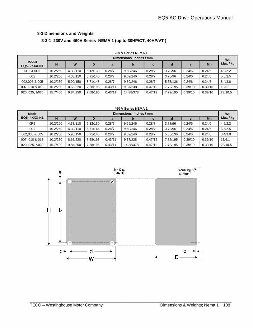
EQ5 AC Drive Operations Manual
_________________________________________________________________________ TECO – Westinghouse Motor Company Dimensions & Weights; Nema 1 108
8-3 Dimensions and Weights 8-3-1 230V and 460V Series NEMA 1 (up to 30HP/CT, 40HP/VT )
230 V Series NEMA 1
Model
EQ5- 2XXX-N1
Dimensions Inches / mm Wt. Lbs. / kg H W D a b c d e Mh
0P2 & 0P5 10.2/260 4.33/110 5.12/130 0.28/7 9.69/246 0.28/7 3.78/96 0.24/6 0.24/6 4.9/2.2 001 10.2/260 4.33/110 5.71/145 0.28/7 9.69/246 0.28/7 3.78/96 0.24/6 0.24/6 5.5/2.5
002,003 & 005 10.2/260 5.90/150 5.71/145 0.28/7 9.69/246 0.28/7 5.35/136 0.24/6 0.24/6 8.4/3.8 007, 010 & 015 10.2/260 8.66/220 7.68/195 0.43/11 9.37/238 0.47/12 7.72/195 0.39/10 0.39/10 13/6.1 020, 025, &030 15.7/400 9.84/250 7.68/195 0.43/11 14.88/378 0.47/12 7.72/195 0.39/10 0.39/10 23/10.5
460 V Series NEMA 1 Model
EQ5- 4XXX-N1 Dimensions Inches / mm Wt.
Lbs. / kg H W D a b c d e Mh 0P5 10.2/260 4.33/110 5.12/130 0.28/7 9.69/246 0.28/7 3.78/96 0.24/6 0.24/6 4.9/2.2 001 10.2/260 4.33/110 5.71/145 0.28/7 9.69/246 0.28/7 3.78/96 0.24/6 0.24/6 5.5/2.5
002,003 & 005 10.2/260 5.90/150 5.71/145 0.28/7 9.69/246 0.28/7 5.35/136 0.24/6 0.24/6 8.4/3.8 007, 010 & 015 10.2/260 8.66/220 7.68/195 0.43/11 9.37/238 0.47/12 7.72/195 0.39/10 0.39/10 13/6.1 020, 025, &030 15.7/400 9.84/250 7.68/195 0.43/11 14.88/378 0.47/12 7.72/195 0.39/10 0.39/10 23/10.5
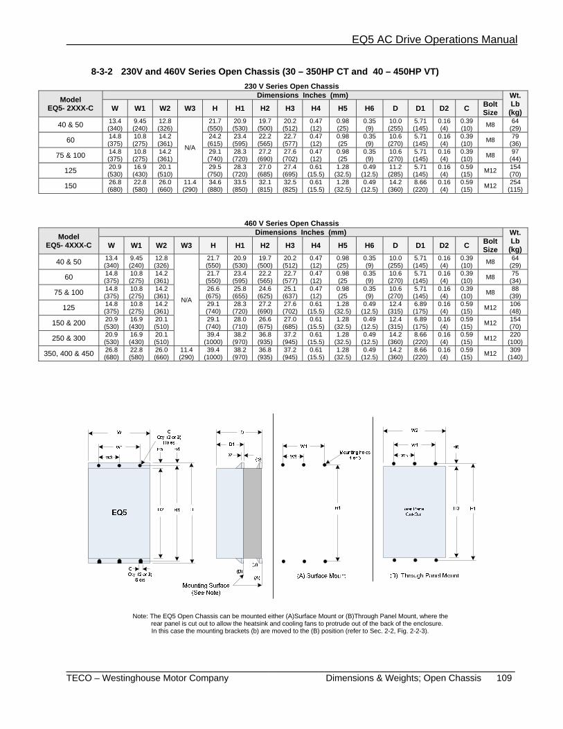
EQ5 AC Drive Operations Manual
_________________________________________________________________________ TECO – Westinghouse Motor Company Dimensions & Weights; Open Chassis 109
8-3-2 230V and 460V Series Open Chassis (30 – 350HP CT and 40 – 450HP VT) 230 V Series Open Chassis
Model EQ5- 2XXX-C
Dimensions Inches (mm) Wt. Lb
(kg) W W1 W2 W3 H H1 H2 H3 H4 H5 H6 D D1 D2 C Bolt Size
40 & 50 13.4 (340)
9.45 (240)
12.8 (326)
N/A
21.7 (550)
20.9 (530)
19.7 (500)
20.2 (512)
0.47 (12)
0.98 (25)
0.35 (9)
10.0 (255)
5.71 (145)
0.16 (4)
0.39 (10) M8 64
(29)
60 14.8 (375)
10.8 (275)
14.2 (361)
24.2 (615)
23.4 (595)
22.2 (565)
22.7 (577)
0.47 (12)
0.98 (25
0.35 (9)
10.6 (270)
5.71 (145)
0.16 (4)
0.39 (10) M8 79
(36)
75 & 100 14.8 (375)
10.8 (275)
14.2 (361)
29.1 (740)
28.3 (720)
27.2 (690)
27.6 (702)
0.47 (12)
0.98 (25
0.35 (9)
10.6 (270)
5.71 (145)
0.16 (4)
0.39 (10) M8 97
(44)
125 20.9 (530)
16.9 (430)
20.1 (510)
29.5 (750)
28.3 (720)
27.0 (685)
27.4 (695)
0.61 (15.5)
1.28 (32.5)
0.49 (12.5)
11.2 (285)
5.71 (145)
0.16 (4)
0.59 (15) M12 154
(70)
150 26.8 (680)
22.8 (580)
26.0 (660)
11.4 (290)
34.6 (880)
33.5 (850)
32.1 (815)
32.5 (825)
0.61 (15.5)
1.28 (32.5)
0.49 (12.5)
14.2 (360)
8.66 (220)
0.16 (4)
0.59 (15) M12 254
(115)
460 V Series Open Chassis Model
EQ5- 4XXX-C
Dimensions Inches (mm) Wt. Lb
(kg) W W1 W2 W3 H H1 H2 H3 H4 H5 H6 D D1 D2 C Bolt Size
40 & 50 13.4 (340)
9.45 (240)
12.8 (326)
N/A
21.7 (550)
20.9 (530)
19.7 (500)
20.2 (512)
0.47 (12)
0.98 (25)
0.35 (9)
10.0 (255)
5.71 (145)
0.16 (4)
0.39 (10) M8 64
(29)
60 14.8 (375)
10.8 (275)
14.2 (361)
21.7 (550)
23.4 (595)
22.2 (565)
22.7 (577)
0.47 (12)
0.98 (25
0.35 (9)
10.6 (270)
5.71 (145)
0.16 (4)
0.39 (10) M8 75
(34)
75 & 100 14.8 (375)
10.8 (275)
14.2 (361)
26.6 (675)
25.8 (655)
24.6 (625)
25.1 (637)
0.47 (12)
0.98 (25
0.35 (9)
10.6 (270)
5.71 (145)
0.16 (4)
0.39 (10) M8 88
(39)
125 14.8 (375)
10.8 (275)
14.2 (361)
29.1 (740)
28.3 (720)
27.2 (690)
27.6 (702)
0.61 (15.5)
1.28 (32.5)
0.49 (12.5)
12.4 (315)
6.89 (175)
0.16 (4)
0.59 (15) M12 106
(48)
150 & 200 20.9 (530)
16.9 (430)
20.1 (510)
29.1 (740)
28.0 (710)
26.6 (675)
27.0 (685)
0.61 (15.5)
1.28 (32.5)
0.49 (12.5)
12.4 (315)
6.89 (175)
0.16 (4)
0.59 (15) M12 154
(70)
250 & 300 20.9 (530)
16.9 (430)
20.1 (510)
39.4 (1000)
38.2 (970)
36.8 (935)
37.2 (945)
0.61 (15.5)
1.28 (32.5)
0.49 (12.5)
14.2 (360)
8.66 (220)
0.16 (4)
0.59 (15) M12 220
(100)
350, 400 & 450 26.8 (680)
22.8 (580)
26.0 (660)
11.4 (290)
39.4 (1000)
38.2 (970)
36.8 (935)
37.2 (945)
0.61 (15.5)
1.28 (32.5)
0.49 (12.5)
14.2 (360)
8.66 (220)
0.16 (4)
0.59 (15) M12 309
(140)
Note: The EQ5 Open Chassis can be mounted either (A)Surface Mount or (B)Through Panel Mount, where the rear panel is cut out to allow the heatsink and cooling fans to protrude out of the back of the enclosure. In this case the mounting brackets (b) are moved to the (B) position (refer to Sec. 2-2, Fig. 2-2-3).
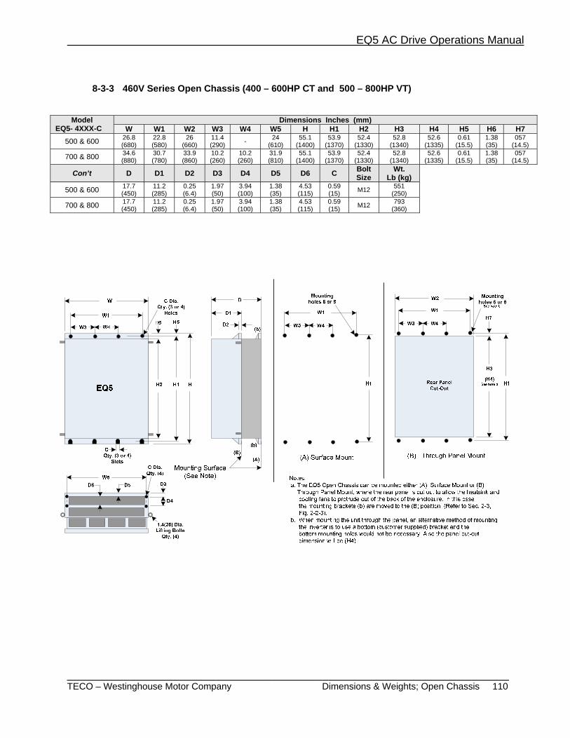
EQ5 AC Drive Operations Manual
_______________________________________________________________________ TECO – Westinghouse Motor Company Dimensions & Weights; Open Chassis 110
8-3-3 460V Series Open Chassis (400 – 600HP CT and 500 – 800HP VT)
Model EQ5- 4XXX-C
Dimensions Inches (mm) W W1 W2 W3 W4 W5 H H1 H2 H3 H4 H5 H6 H7
500 & 600 26.8 (680)
22.8 (580)
26 (660)
11.4 (290) - 24
(610) 55.1
(1400) 53.9
(1370) 52.4
(1330) 52.8
(1340) 52.6
(1335) 0.61
(15.5) 1.38 (35)
057 (14.5)
700 & 800 34.6 (880)
30.7 (780)
33.9 (860)
10.2 (260)
10.2 (260)
31.9 (810)
55.1 (1400)
53.9 (1370)
52.4 (1330)
52.8 (1340)
52.6 (1335)
0.61 (15.5)
1.38 (35)
057 (14.5)
Con’t D D1 D2 D3 D4 D5 D6 C Bolt Size
Wt. Lb (kg)
500 & 600 17.7 (450)
11.2 (285)
0.25 (6.4)
1.97 (50)
3.94 (100)
1.38 (35)
4.53 (115)
0.59 (15) M12 551
(250)
700 & 800 17.7 (450)
11.2 (285)
0.25 (6.4)
1.97 (50)
3.94 (100)
1.38 (35)
4.53 (115)
0.59 (15) M12 793
(360)
EQ5 AC Drive Operations Manual
_______________________________________________________________________ TECO – Westinghouse Motor Company Dimensions & Weights; DC Link Choke 111
8-3-4 DC Link Choke for (75 –600HP CT and 100 – 800HP VT)
230 V Series Open Chassis
Inverter Model EQ-2XXX-C
DC Choke Model
Dimensions Inches (mm) Wt. lbs (kg)
A B C D E F G H J Terminal hole size
100 DCR2-75B 7.87 (200)
6.69 (170)
3.94 (100)
5.55 (141)
4.33 (110)
2.76 (70)
0.39(10)
8.27 (210) N/A M12 40
(18)
125 DCR2-90B 7.09 (180)
5.91 (150)
4.33 (110)
5.94 (151)
5.51 (140)
2.95 (75)
0.39(10)
9.45 (240)
0.98 (25) φ15 44
(20)
150 DCR2-110B 7.48 (190)
6.30 (160)
4.72 (120)
6.34 (161)
5.91 (150)
3.15 (80)
0.39(10)
10.6 (270)
0.98 (25) φ15 55
(25)
460 V Series Open Chassis
Inverter Model EQ-4XXX-C
DC Choke Model
Dimensions Inches (mm) Wt. lbs (kg) A B C D E F G H J K L Terminal
hole size100 DCR4-75B 7.48
(190) 6.30 (160)
4.53(115)
5.94(151)
3.94(100)
2.95(75)
0.39(10)
9.45(240) —
N/A N/A
M10 44(20)
125 DCR4-90B 7.48 (190)
6.30 (160)
4.92(125)
6.34(161)
4.72(120)
3.15(80)
0.39(10)
9.84(250)
0.98(25) φ12 50
(23)150 DCR4-110B 7.48
(190) 6.30 (160)
4.92(125)
6.34(161)
4.72(120)
3.15(80)
0.39(10)
9.84(250)
0.98(25) φ12 55
(25)200 DCR4-132B 7.87
(200) 6.69 (170)
5.31(135)
6.73(171)
4.72(120)
3.35(85)
0.39(10)
10.2(260)
1.18(30) φ12 62
(28)250 DCR4-160B 8.27
(210) 7.09 (180)
5.31(135)
6.73(171)
4.72(120)
3.35(85)
0.47(12)
11.4(290)
1.18(30) φ12 71
(32)300 DCR4-200B 8.27
(210) 7.09 (180)
5.31(135)
6.73(171)
5.51(140)
3.54(90)
0.47(12)
11.6(295)
1.18(30) φ12 77
(35)350 DCR4-220B 8.66
(220) 7.48 (190)
5.31(135)
6.73(171)
5.51(140)
3.54(90)
0.47(12)
11.8(300)
1.57(40) φ15 88
(40)
400 & 450 DCR4-280B 8.66 (220)
7.48 (190)
5.71(145)
7.13(181)
5.91(150)
3.74(95)
0.47(12)
12.6(320)
1.57(40) φ15 99
(45)
500 DCR4-355B 8.66 (220)
7.48 (190)
5.71(145)
7.13(181)
6.30(160)
3.74(95)
0.47(12)
12.6(320)
1.57(40) φ15 121
(55)
600 DCR4-400B 9.45 (240)
8.27 (210)
5.71(145)
7.13(181)
6.69(170)
3.74(95)
0.47(12)
13.4(340)
1.57(40)
1.77 (45)
8.86 (225) φ15 132
(60)
700 DCR4-450B 10.2 (260)
8.86 (225)
5.71(145)
7.13(181)
6.69(170)
3.74(95)
0.47(12)
13.4(340)
1.97(50)
1.77 (45)
8.86 (225) φ15 148
(67)
800 DCR4-500B 10.2 (260
8.86 (225)
5.71(145)
7.13(181)
7.28(185)
3.94(100)
0.47(12)
13.4(340)
1.97(50)
1.77 (45)
8.86 (225) φ15 154
(70)
EQ5 AC Drive Operations Manual
_______________________________________________________________________ TECO – Westinghouse Motor Company Serial Communications Modbus 112
8-4 RS-485 Modbus RTU Serial Communications The serial communications interface supports operation, configuration and monitoring of inverter functions through an EIA/RS-485 connection. The serial interface is based on Modbus RTU protocol. This protocol allows the inverter to function as an RTU slave on an industrial network.
8- 4-1 Transmission Specifications Item Specification
Physical level EIA/RS-485 Transmission distance 1600 ft (500 m) Number of nodes 32 total Transmission speed 19200, 9600, 4800, 2400 [bits/s] Transmission mode Half duplex Transmission protocol Modbus RTU Character code Binary Character length 8 bits Error check CRC
8- 4-2 Connection
Connection method: Use shielded wire and connect to the control terminals (DX-, DX+ and SD). A terminating resistor should be added between the data lines on the each end of the network. The value of the terminating resistor depends on the characteristic impedance of the cable. A common value is 120 ohms. Control terminals:
Terminal Designation Terminal Name Function Description
DX+ RS-485 communication data (+) Input/output terminals for RS-485 communication. DX- RS-485 communication data (–)
SD Cable shield Electrically floating
8- 4-3 Serial Interface Configuration Inverter function codes H30 to H39 are used to configure the serial interface parameters, such as device address, baud rate and error response.
8- 4- 4 Modbus RTU Functions The following RTU functions are supported. The maximum number of consecutive parameters for function 03 and 16 messages is 16.
Code Description
03 Read Holding Registers (16 registers maximum) 06 Preset Single Register 16 Preset Multiple Registers (16 registers maximum)
EQ5 AC Drive Operations Manual
_______________________________________________________________________ TECO – Westinghouse Motor Company Serial Communications Modbus 113
8-4-5 Inverter Function Code Access All of the inverter function codes are accessible through the RS-485 serial interface. Inverter function codes are mapped to RTU holding registers. An inverter function code RTU address is 2 bytes in length. The high byte corresponds to a code that represents the inverter parameter sort (F–M). The low byte corresponds to the inverter parameter number within the sort (0 -99).
high byte low byte
inverter parameter sort code inverter parameter number
Code Sort Name Code Sort Name 0 F Basic function 5 A Motor 2 function 1 E Terminal function 6 o Option function 2 C Control function 7 S Command/function data 3 P Motor 1 function 8 M Monitor data 4 H High level function
For example, inverter function code M11 the output current, is addressed as RTU parameter number 080B hexadecimal or 2059 decimal.
8-4-6 Command and Monitor Data Registers
The command and monitor function codes are used to control the operation of the inverter and monitor the status variables through the serial interface. The command and monitor function codes are not accessible from the inverter keypad interface. Inverter parameter H30 and digital input signal LE must be enabled to operate the inverter from the Modbus interface. If LE is not assigned to a digital input (X1-X9), the signal will default to ON. Frequency Setting Registers:
Address Code Name Unit Variable Range Min. Unit
Read/Write
Data Format
1793 S01 Frequency command - -20000–20000 (max. frequency at ± 20000) 1 R/W 2
1797 S05 Frequency command Hz 0.00–120.00 0.01 R/W 5 Notes: 1) If both S01 and S05 are set, the inverter will ignore the setting of S05. 2) A data setting that exceeds the setting range is possible, but the actual action will be limited by the inverter configuration. Operation command data Registers:
Address Code Name Unit Variable Range Min. Unit
Read/Write
Data Format
1798 S06 Operation command - Refer to the data format [14] - R/W 14 1799 S07 Universal Do - Refer to the data format [15] - R/W 15
1804 S12 Universal Ao - -20000–20000 (100% output at ± 20000 ) 1 R/W 2
Notes: 1) Since X1–X9 are configurable input commands, it is necessary to set the functions by E01–E09.
2)The alarm reset is executed, when RST signal changes from ON to OFF even if there are no alarms.
3) Universal Do is a function that utilizes the inverter’s digital outputs via communication.

EQ5 AC Drive Operations Manual
_______________________________________________________________________ TECO – Westinghouse Motor Company Serial Communications Modbus 114
Function data Registers
Address Code Name Unit Variable Range Min. Unit
Read/Write
Data Format
1800 S08 Acceleration time F07 s 0.1–3600.0 0.1 R/W 3 1801 S09 Deceleration time F08 s 0.1–3600.0 0.1 R/W 3
1802 S10 Torque limit level 1 (driving) F40 % 20.00 –200.00, 999
(EQ5:20.00-150.00) 1.00 R/W 5
1803 S11 Torque limit level 2 (braking) F41 % 0.00, 20.00–200.00, 999
(EQ5:20.00-150.00) 1.00 R/W 5
Notes: 1) The writing of data out of range is treated as out of range error. 2) Use a value of 7FFFH to enter 999 for torque limit functions. Monitoring parameter registers
Address Code Description Unit Range Min. Unit Read/Write Data
Format
2049 M01 Frequency command (final command) -
- 20000–20000 (max. frequency at ± 20000)
1 R [2]
2053 M05 Frequency command (final command) Hz 0.00-120.00) 0.01 R [5]
2054 M06 Actual frequency
- - 20000–20000 (max. frequency at ± 20000)
1 R [2]
2055 M07 Actual torque value % - 200.00–200.00 0.01 R [6] 2056 M08 Torque current % - 200.00–200.00 0.01 R [6] 2057 M09 Output frequency Hz 0.00-120.00) 0.01 R [5]
2058 M10 Motor output (input electric power) % 0.00–200.00 0.01 R [5]
2059 M11 Output current r. m. s. % 0.00–200.00 (inverter rating at 100.00) 0.01 R [5]
2060 M12 Output voltage r. m. s. V 0.0–600.0 1.0 R [3]
2061 M13 Operation command (final command) - Refer to data format
[14] - R [14]
2062 M14 Operating state - Refer to data format [16] - R [16]
2063 M15 Universal output terminal data - Refer to data format
[15] - R [15]
2064 M16 Fault memory 0
- Refer to data format [10] - R [10] 2065 M17 Fault memory 1
2066 M18 Fault memory 2 2067 M19 Fault memory 3
2068 M20 Integrated operating time h 0–65535 1 R [1]
2069 M21 DC link voltage V 0–1000 1 R [1]
2071 M23 Type code - Refer to data format [17] - R [17]
2072 M24 Inverter capacity code - Refer to data format [11] - R [11]
Cont.
EQ5 AC Drive Operations Manual
_______________________________________________________________________ TECO – Westinghouse Motor Company Serial Communications Modbus 115
2073 M25 ROM version - 0–64999 1 R [1] 2074 M26 Transmission error processing code - Refer to data format [20] - R [20]
2075 M27 Frequency command at alarm (final command) - - 20000–20000 (max. frequency
at ±20000 ) 1 R [2]
2079 M31 Frequency command at alarm (final command) Hz 0.00-120.00) 0.01 R [5]
2080 M32 Actual frequency at alarm - - 20000–20000 (max. frequency at ± 20000) 1 R [2]
2081 M33 Actual torque at alarm % - 200.00 – 200.00 0.01 R [6] 2082 M34 Torque current at alarm % - 200.00 – 200.00 0.01 R [6] 2083 M35 Output frequency at alarm Hz 0.00 – 120.00 0.01 R [5] 2084 M36 Motor output at alarm (input power) % 0.00–200.00 0.01 R [5]
2085 M37 Output current rms. at alarm % 0.00 – 200.00 (inverter rating at 100.00) 0.01 R [5]
2086 M38 Output voltage effective value at alarm V 0.0 – 600.0 1.0 R [3]
2087 M39 Operation command at alarm - Refer to data format [14] - R [14]2088 M40 Operating state at alarm - Refer to data format [16] - R [16]
2089 M41 Universal output terminal data at alarm - Refer to data format [15] - R [15]
2090 M42 Integrated operation time at alarm h 0–65535 1 R [1] 2091 M43 DC link voltage at alarm V 0–1000 1 R [1] 2092 M44 Inverter internal air temp.at alarm °C 0–120 1 R [1] 2093 M45 Cooling fin temp. at alarm °C 0–120 1 R [1] 2094 M46 Life of main circuit capacitor. % 0.0–100.0 0.1 R [3] 2095 M47 Life of printed circuit board capacitor. h 0–65535 1 R [1] 2096 M48 Life of cooling fan. h 0–65535 1 R [1]
8-4-7 Data Format Specification All data in the data field of communication frame shall be represented by a 16 bit length word.
15 14 13 12 11 10 9 8 7 6 5 4 3 2 1 0
16 bits binary data
Data format [1] Unsigned Integer data (Positive): Min. unit 1 Example: F15 (Frequency limit, upper)= 60Hz 60 = 003CH
Data format [2] Integer data (Positive, negative): Min. unit 1 Example: data = -20 -20 = FFECH Data format [3] Unsigned Decimal data (Positive): Min. unit 0.1
Example: F17 (frequency gain setting signal) = 100.0% 100.0 X 10 = 1000 = 03E8H
Data format [4] Decimal data (Positive, negative): Min. unit 0.1
Example: C31 (Analog input offset adjust, term.12) = - 5.0% - 5.0 X 10= - 50 = FFCEH
Data format [5] Unsigned Decimal data (Positive): Min. unit 0.01 Example: C05 (multi-step frequency 1) = 50.25Hz 50.25 X 100 = 5025 = 13A1H
EQ5 AC Drive Operations Manual
_______________________________________________________________________ TECO – Westinghouse Motor Company Serial Communications Modbus 116
Data format [6] Decimal data (Positive, negative): Min. unit 0.01
Example: M07 (actual torque value)= - 85.38% - 85.38 X 100= - 8538=DEA6H Data format [7] Unsigned Decimal data (Positive): Min. unit 0.001
Example: If o05 (follow - up side ASR 1 constant) = 0.105s 0.105 X 1000 = 105 = 0069H
Data format [8] Decimal data (Positive, negative): Min. unit 0.001
Example: Data = -1.234 - 1.234 X 1000 = - 1234 = FB2EH Data format [9] Unsigned Integer data (Positive): Min. unit 2
Example If P01 (Motor 1 number of poles) =2pole 2 = 0002H Data format [10] Alarm code:
Code Description Code Description 0 No alarm - 22 Overheat, DB resistor dbH 1 Overcurrent, during acceleration (INV output ) OC1 23 Overload, motor 1 OL1 2 Overcurrent, during deceleration (INV output ) OC2 24 Overload, motor 2 OL2
3 Overcurrent, during steady state operation (INV output ) OC3 25 Overload, inverter OLU
5 Ground fault EF 27 Overspeed OS 6 Overvoltage, during acceleration OU1 28 PG wire break Pg 7 Over voltage, during deceleration OU2 31 Memory error Er1 8 Overvoltage, during steady state operation OU3 32 Keypad error Er2 10 DC undervoltage LU 33 CPU error Er3 11 Power supply open phase Lin 34 Option comm. error Er4 14 Blown DC fuse FUS 35 Option error Er5 16 Output wiring error Er7 36 PL error Er6 17 Overheat, heat sink, inverter OH1 37 Output wiring error Er7 18 Overheat, outside thermal OH2 38 RS-485 comm. error Er8 19 Overheat, unit inside temp. OH3
Data format [11] Capacity code:
Code Capacity (HP) Code Capacity
(HP) Code Capacity (HP)
7 0.07(spare) 2000 20 20000 200 15 0.15(spare) 2500 25 25000 250 25 0.25 3000 30 30000 300 50 0.5 4000 40 35000 350 100 1 5000 50 40000 400 200 2 6000 60 45000 450 300 3 7500 75 50000 500 500 5 10000 100 60600 600 750 7.5 12500 125 60700 700
1000 10 15000 150 60800 800 1500 15 17500 175
EQ5 AC Drive Operations Manual
_______________________________________________________________________ TECO – Westinghouse Motor Company Serial Communications Modbus 117
Data format [12] Index data (ACC/DEC time, display coefficient):
15 14 13 12 11 10 9 8 7 6 5 4 3 2 1 0
Polarity 0 0 0 Index portion Data portion 0: Positive (+), 0: 0.01 X 001–999 (0.00–9.99) 1: 0.1 X 100–999 (10.0–99.9) 1: Negative ( - ) 2: 1 X 100–999 (100–999) 3: 10 X 100–999 (1000–9990) Example: F07 (acceleration time 1) = 20.0 s
10.0 < 20< 99.9 → index =1 20.0 = 0.1 X 200 → 0400H + 00C8H = 04C8H
Data format [13] Pattern operation:
15 14 13 12 11 10 9 8 7 6 5 4 3 2 1 0
Directionof
rotation 0 Time Index portion Data portion
0: 1st ACC/DEC time 0: 0.01 X 001–999 (0.00–9.99) 0: FWD 1: 2nd ACC/DEC time 1: 0.1 X 100–999 (10.0–99.9) 1: REV 2: 3rd ACC/DEC time 2: 1 X 100–999 (100–999) 3: 4th ACC/DEC time 3: 10 X 100–999 (1000–9990)
Example: C22 (Stage1) = 10.0s R2 (10s, reverse rotation, acceleration time 2/deceleration time 2) Since 10.0 = 0.1 X 100 > 9000H + 0400H + 0064H = 9464H
Data format [14] Operation command:
15 14 13 12 11 10 9 8 7 6 5 4 3 2 1 0
RST 0 0 0 0 X9 X8 X7 X6 X5 X4 X3 X2 X1 REV FWD
(All bit are ON by 1) Example: S06 (operation command) = FWD, X1 and X5 = ON
0000 0000 0100 0101b = 0045H
Data format [15] Universal output terminal:
15 14 13 12 11 10 9 8 7 6 5 4 3 2 1 0
0 0 0 0 0 0 0 0 0 0 0 Y5 Y4 Y3 Y2 Y1
(All bit are ON by 1) Example: M15 (Universal output terminal)=Y1 and Y5 = ON
0000 0000 0001 0001b = 0011H

EQ5 AC Drive Operations Manual
_______________________________________________________________________ TECO – Westinghouse Motor Company Serial Communications Modbus 118
Data format [16] Operating state:
15 14 13 12 11 10 9 8 7 6 5 4 3 2 1 0
BUSY WR RL ALM DEC ACC IL VL TL NUV BRK INT EXT REV FWD
(All bit are ON or active by 1) FWD: Forward operation IL: Current limiting REV: Reverse operation ACC: Under acceleration EXT: DC braking active (or pre-excitation) DEC: Under deceleration ALM: Inverter fault INT: No Output RL: Transmission valid BRK: Braking active WR: Function writing privilege NUV: DC link voltage is established 0: Keypad panel (undervoltage at 0) 1: RS-485 TL: Torque limiting 2: Fieldbus (option) VL: Voltage limiting BUSY: Processing data write
Data format [17] Type code:
15 14 13 12 11 10 9 8 7 6 5 4 3 2 1 0 Type Generation Series Voltage series
Code Type Generation Series Voltage series
1 - EQ5 - - 2 - - - - 3 EQ5 - - 230V three phase 4 - - - 460V three phase 5 - - USA 575V three phase 6 - - - -
Data format [18] Code setting (1–4 figures):
15 14 13 12 11 10 9 8 7 6 5 4 3 2 1 0 Data 4 Data 3 Data 2 Data 1
Data format [19] Amperage value Decimal data (positive ):
Min. unit 0.01 inverter capacity is not more than 30HP/CT, 40HP/VT. Min unit 0.01 for not less than 40HP/CT, 50HP/CT.
Example: F11 (electronics thermal overload relay 1 level) 107.0A (40HP) 107.0 X 10=1070=042EH F11 (electronics thermal overload relay 1 level) =3.60A (1HP) 3.60 X 100=360=0168H
EQ5 AC Drive Operations Manual
_______________________________________________________________________ TECO – Westinghouse Motor Company Communications Errors 119
Data format [20] Transmission error code:
Code Description Code Description 1 FC (function code) error 71 CRC error (no response) 2 Illegal address 72 Parity error (no response)
3 Illegal address (Data range error) 73
Other errors (no response) -Framing error -Overrun error -Buffer full error
7
NAK -Priority for comm. -No privilege for writing error -Forbidden writing error
Data format [21] Auto tuning: 15 14 13 12 11 10 9 8 7 6 5 4 3 2 1 0
0 0 0 0 0 0 REV FWD Data portion 0: Without forward rotation command 1: With forward rotation command. 0: Without reverse rotation command. 1: With reverse rotation command.
Example: P04 (motor 1 auto - tuning)=1: Forward rotation
0000 0001 0000 0001b=0101H
8-4-8 Communication Errors (Exception Response) When the inverter receives a message that does not contain communication errors but the message can not be processed, the inverter will return an exception response. The exception response contains an error sub-code in the data field that represents the problem.
Exception Response Errors:
Sub-Code
Name Causes
1 Illegal Function Received RTU Function other than 03, 06 or 16
2 Illegal Data Address
• The starting parameter address is an unused inverter parameter. • The starting parameter address plus the offset refers to inverter
parameter greater than the last parameter in a Function Code sort.
• The number of registers is greater than 16. 3 Illegal Data Value Data contains an out of range value for an inverter parameter
7 Negative Acknowledge
• Requested data cannot be changed while the inverter is running. • The inverter parameter function is owned by the network interface
option card and cannot be changed. Communication errors: Communication errors occur when the inverter receives an invalid message. The inverter will not return a response to a communication error. A code that represents the last communication error is stored in inverter parameter M26. Typical communication message errors include parity, framing, and CRC errors.
EQ5 AC Drive Operations Manual
__________________________________________________________________________ TECO – Westinghouse Motor Company Options 120
9. Options The inverter supports two internally mounted cards. One option card is mounted under the main cover (Location A) and the other option card is mounted in a special adapter under the keypad (Location B). Only one card can be mounted in these locations. There are two different types of option cards, Type 1 and Type 2. You cannot use two Type 1 or Two Type 2 cards but you can mix any combination of Type 1 and Type 2 provided you only have one option per mounting location. Each option card must be mounted in the designated location. The chart below lists the option card, their types, and their mounting locations.
Name Type Loc.2nd
Option Type/Loc
Function
OPC-G11S-RY (Relay output card) 1 A 2/B
• Relay output card The transistor output from the inverter control output terminals Y1 and Y4 are converted to the relay output (1SPDT).
OPC-G11S-DIO (Digital interface card) 2 A None
• Frequency setting by binary code (max. 16 bits) • Monitoring (8 bits) of frequency, output current,
and output voltage
OPC-G11S-AIO (Analog interface card)
2 A None
• Auxiliary input for analog frequency setting (0 to +/-10 V)
• Monitoring of inverter output frequency, current, and torque in analog voltage, analog output 0-10 VDC and 4-20mA
OPC-G11S-PDP (Communication card) 2 B 1/A • Serial communication card for Profibus-DP
OPC-G11S-DEV (Communication card) 2 B 1/A • Serial communication card for Device Net
OPC-G11S-COP (Communication card) 2 B 1/A • Serial communication card for CAN
OPC-G11S-MBP (Communication card) 2 B 1/A • Serial communication card for Modbus plus
OPC-G11S-IBS (Communication card) 2 B 1/A • Serial communication card for Interbus-S
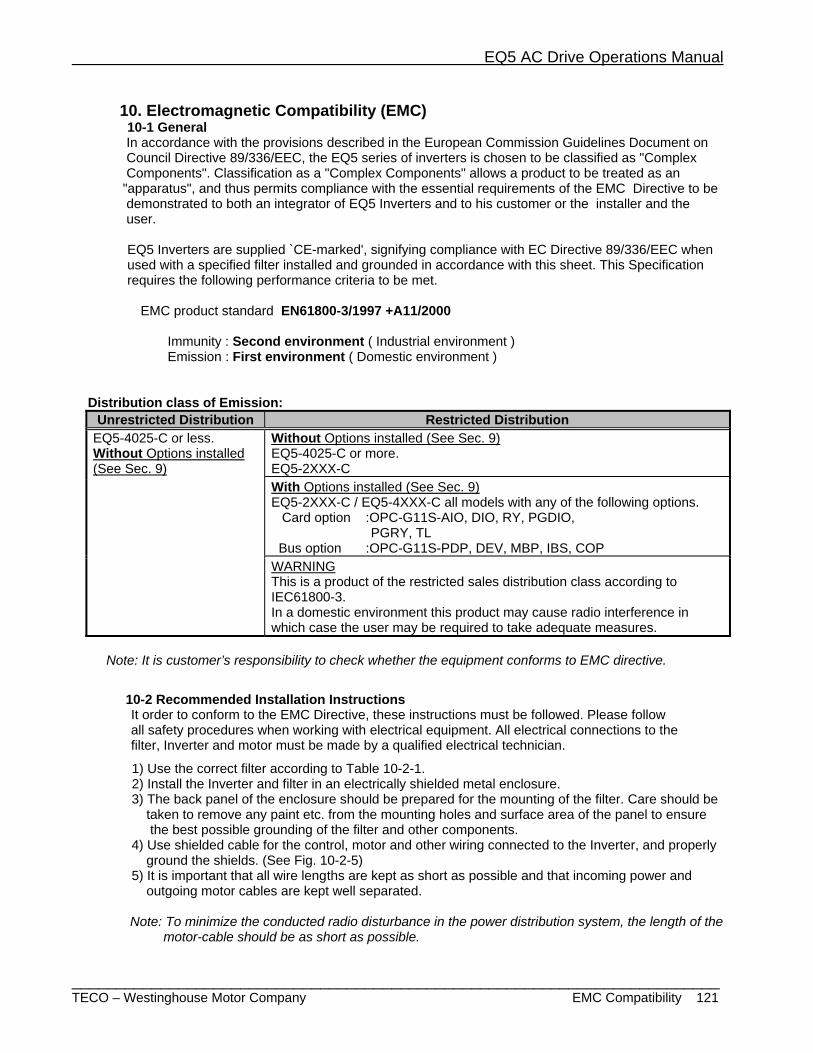
EQ5 AC Drive Operations Manual
_________________________________________________________________________ TECO – Westinghouse Motor Company EMC Compatibility 121
10. Electromagnetic Compatibility (EMC) 10-1 General In accordance with the provisions described in the European Commission Guidelines Document on Council Directive 89/336/EEC, the EQ5 series of inverters is chosen to be classified as "Complex Components". Classification as a "Complex Components" allows a product to be treated as an "apparatus", and thus permits compliance with the essential requirements of the EMC Directive to be demonstrated to both an integrator of EQ5 Inverters and to his customer or the installer and the user.
EQ5 Inverters are supplied `CE-marked', signifying compliance with EC Directive 89/336/EEC when used with a specified filter installed and grounded in accordance with this sheet. This Specification requires the following performance criteria to be met.
EMC product standard EN61800-3/1997 +A11/2000
Immunity : Second environment ( Industrial environment ) Emission : First environment ( Domestic environment )
Distribution class of Emission: Unrestricted Distribution Restricted Distribution
EQ5-4025-C or less. Without Options installed (See Sec. 9)
Without Options installed (See Sec. 9) EQ5-4025-C or more. EQ5-2XXX-C With Options installed (See Sec. 9) EQ5-2XXX-C / EQ5-4XXX-C all models with any of the following options.
Card option :OPC-G11S-AIO, DIO, RY, PGDIO, PGRY, TL
Bus option :OPC-G11S-PDP, DEV, MBP, IBS, COP WARNING This is a product of the restricted sales distribution class according to IEC61800-3. In a domestic environment this product may cause radio interference in which case the user may be required to take adequate measures.
Note: It is customer’s responsibility to check whether the equipment conforms to EMC directive.
10-2 Recommended Installation Instructions It order to conform to the EMC Directive, these instructions must be followed. Please follow all safety procedures when working with electrical equipment. All electrical connections to the filter, Inverter and motor must be made by a qualified electrical technician.
1) Use the correct filter according to Table 10-2-1. 2) Install the Inverter and filter in an electrically shielded metal enclosure. 3) The back panel of the enclosure should be prepared for the mounting of the filter. Care should be taken to remove any paint etc. from the mounting holes and surface area of the panel to ensure the best possible grounding of the filter and other components. 4) Use shielded cable for the control, motor and other wiring connected to the Inverter, and properly ground the shields. (See Fig. 10-2-5) 5) It is important that all wire lengths are kept as short as possible and that incoming power and outgoing motor cables are kept well separated.
Note: To minimize the conducted radio disturbance in the power distribution system, the length of the motor-cable should be as short as possible.
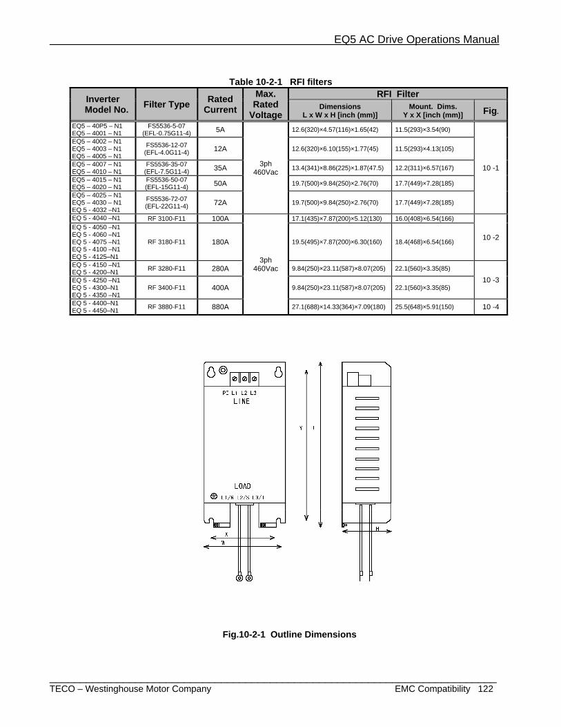
EQ5 AC Drive Operations Manual
_________________________________________________________________________ TECO – Westinghouse Motor Company EMC Compatibility 122
Table 10-2-1 RFI filters
Inverter Model No. Filter Type Rated
Current Max. Rated
Voltage
RFI Filter Dimensions
L x W x H [inch (mm)] Mount. Dims.
Y x X [inch (mm)] Fig.
EQ5 – 40P5 – N1 EQ5 – 4001 – N1
FS5536-5-07 (EFL-0.75G11-4) 5A
3ph 460Vac
12.6(320)×4.57(116)×1.65(42) 11.5(293)×3.54(90)
10 -1
EQ5 – 4002 – N1 EQ5 – 4003 – N1 EQ5 – 4005 – N1
FS5536-12-07 (EFL-4.0G11-4) 12A 12.6(320)×6.10(155)×1.77(45) 11.5(293)×4.13(105)
EQ5 – 4007 – N1 EQ5 – 4010 – N1
FS5536-35-07 (EFL-7.5G11-4) 35A 13.4(341)×8.86(225)×1.87(47.5) 12.2(311)×6.57(167)
EQ5 – 4015 – N1 EQ5 – 4020 – N1
FS5536-50-07 (EFL-15G11-4) 50A 19.7(500)×9.84(250)×2.76(70) 17.7(449)×7.28(185)
EQ5 – 4025 – N1 EQ5 – 4030 – N1 EQ 5 - 4032 –N1
FS5536-72-07 (EFL-22G11-4) 72A 19.7(500)×9.84(250)×2.76(70) 17.7(449)×7.28(185)
EQ 5 - 4040 –N1 RF 3100-F11 100A
3ph 460Vac
17.1(435)×7.87(200)×5.12(130) 16.0(408)×6.54(166)
10 -2 EQ 5 - 4050 –N1 EQ 5 - 4060 –N1 EQ 5 - 4075 –N1 EQ 5 - 4100 –N1 EQ 5 - 4125–N1
RF 3180-F11 180A 19.5(495)×7.87(200)×6.30(160) 18.4(468)×6.54(166)
EQ 5 - 4150 –N1 EQ 5 - 4200–N1 RF 3280-F11 280A 9.84(250)×23.11(587)×8.07(205) 22.1(560)×3.35(85)
10 -3 EQ 5 - 4250 –N1 EQ 5 - 4300–N1 EQ 5 - 4350 –N1
RF 3400-F11 400A 9.84(250)×23.11(587)×8.07(205) 22.1(560)×3.35(85)
EQ 5 - 4400–N1 EQ 5 - 4450–N1 RF 3880-F11 880A 27.1(688)×14.33(364)×7.09(180) 25.5(648)×5.91(150) 10 -4
Fig.10-2-1 Outline Dimensions

EQ5 AC Drive Operations Manual
_________________________________________________________________________ TECO – Westinghouse Motor Company EMC Compatibility 123
Filter Type
Dimensions [inch(mm)]
W W1 H H1 D RF3100-F11 7.87 (200) 6.54 (166) 17.1 (435) 16.1 (408) 5.12 (130) RF3180-F11 7.87 (200) 6.54 (166) 19.5 (495) 18.4 (468) 6.30 (160)
Fig.10-2-2 Outline Dimensions
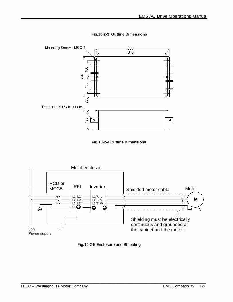
EQ5 AC Drive Operations Manual
_________________________________________________________________________ TECO – Westinghouse Motor Company EMC Compatibility 124
Fig.10-2-3 Outline Dimensions
Fig.10-2-4 Outline Dimensions
L1/R U L2/S V L3/T W
L1 L1’ L2 L2’ L3 L3’ PE
M
InverterRFIRCD or MCCB
3ph Power supply
Metal enclosure
Shielded motor cable Motor
Fig.10-2-5 Enclosure and Shielding
Shielding must be electrically continuous and grounded at the cabinet and the motor.

Top Related