


Languages
Pages
Legal


Engineer’s quick reference guide FOR GROUND INVESTIGATION
www.rsk.co.uk

02 STANDARDS AND CODES OF PRACTICE
STANDARDS AND CODES OF PRACTICE
Example standards and codes of practice
BS 5930:2015 Code of practice for ground investigations
BS 10175:2011 Investigation of potentially contaminated sites – Code of practice
– UK Specification for Ground Investigation
BS EN 1997 Eurocode 7: Geotechnical design (parts 1 and 2)
BS EN ISO 14688 Geotechnical investigation and testing – Identification and classification of soil (parts 1 and 2)
BS EN ISO 14689 Geotechnical investigation and testing – Identification and classification of rock (part 1)
BS EN ISO 22475 Geotechnical investigation and testing – Sampling methods and groundwater measurements (Parts 1–3)
BS EN ISO 22476 Geotechnical investigation and testing – Field testing (parts 1–12)
BS EN ISO 22282 Geotechnical investigation and testing – Geohydraulic testing (parts 1–6)
BS 1377:1990 Methods of test for soils for civil engineering purposes (parts 1–9)
BS EN ISO 17892 Geotechnical investigation and testing – Laboratory testing of soil (multiple parts)
Note: Where standards have been amended (e.g. BS 10175:2011 + A1:2013), the amendment number and date have been omitted from the above list for clarity. Information obtained from British Standards © BSI.
This guide does not purport to replace or supersede any British Standard, and should not be relied upon as if it were one. RSK shall not be liable for any losses, actions, claims, proceedings, demands, costs, expenses, damages or other liabilities whatsoever or however caused, arising directly or indirectly in connection with, in relation to, or arising from the use of this guide.
RSK‘S SERVICES
n Site investigationn Drillingn Risk assessmentn Remediation options appraisaln Remedial designn Laboratory testingn Expert witnessn Due diligencen Waste managementn Air and noise qualityn Earthworks modellingn Civil and structural engineering

Drilling rigs and investigation equipment

04 DRILLING RIGS AND INVESTIGATION EQUIPMENT
Dando 2000
Mass (unladen) 1700 kg
Working height 6.65 m
Length during transit 7.5 m
Height during transit 1.75 m
Usual delivery method
Towed by 4WD vehicle
Working space requirements
Preferably 10 × 3 m
Dando 2500
Mass (unladen) 1995 kg
Working height 6.83 m
Length during transit 8.45 m
Height during transit 1.8 m
Usual delivery method
Towed by 4WD vehicle
Working space requirements
Preferably 10 x 3 m
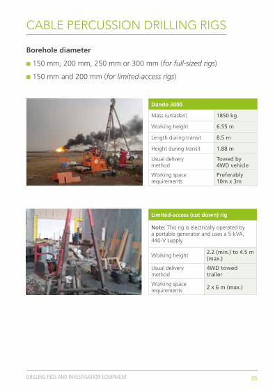
CABLE PERCUSSION DRILLING RIGS
Cable percussion drilling
n Suitable for drilling soil and weak rock
n Able to penetrate most rocks only short distances
n Borehole depths of up to 90 m achievable in suitable ground (30 m for limited-access rig)
05DRILLING RIGS AND INVESTIGATION EQUIPMENT
Dando 3000
Mass (unladen) 1850 kg
Working height 6.55 m
Length during transit 8.5 m
Height during transit 1.88 m
Usual delivery method
Towed by 4WD vehicle
Working space requirements
Preferably 10m x 3m
Limited-access (cut down) rig
Note: This rig is electrically operated by a portable generator and uses a 5-kVA, 440-V supply.
Working height2.2 (min.) to 4.5 m (max.)
Usual delivery method
4WD towed trailer
Working space requirements
2 x 6 m (max.)
CABLE PERCUSSION DRILLING RIGS
Borehole diameter
n 150 mm, 200 mm, 250 mm or 300 mm (for full-sized rigs)
n 150 mm and 200 mm (for limited-access rigs)
06 DRILLING RIGS AND INVESTIGATION EQUIPMENT
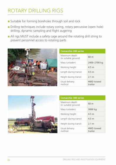
Comacchio 200 series
Maximum depth (in suitable ground)
60 m
Mass (unladen) 2400–2700 kg
Working height 4.5 m
Length during transit 4.5 m
Height during transit 2.1 m
Usual delivery method
4WD towed trailer
Comacchio 300 series
Maximum depth (in suitable ground)
60 m
Mass (unladen) 3000 kg
Working height 4.5 m
Length during transit 4.5 m
Height during transit 2.1 m
Usual delivery method
4WD towed trailer
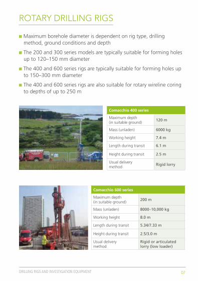
ROTARY DRILLING RIGS
n Suitable for forming boreholes through soil and rock
n Drilling techniques include rotary coring, rotary percussive (open hole) drilling, dynamic sampling and flight augering
n All rigs MUST include a safety cage around the rotating drill string to prevent personnel access to rotating parts
07DRILLING RIGS AND INVESTIGATION EQUIPMENT
Comacchio 400 series
Maximum depth (in suitable ground)
120 m
Mass (unladen) 6000 kg
Working height 7.4 m
Length during transit 6.1 m
Height during transit 2.5 m
Usual delivery method
Rigid lorry
Comacchio 600 series
Maximum depth (in suitable ground)
200 m
Mass (unladen) 8000–10,000 kg
Working height 8.0 m
Length during transit 5.34/7.33 m
Height during transit 2.5/3.0 m
Usual delivery method
Rigid or articulated lorry (low loader)
ROTARY DRILLING RIGS
n Maximum borehole diameter is dependent on rig type, drilling method, ground conditions and depth
n The 200 and 300 series models are typically suitable for forming holes up to 120–150 mm diameter
n The 400 and 600 series rigs are typically suitable for forming holes up to 150–300 mm diameter
n The 400 and 600 series rigs are also suitable for rotary wireline coring to depths of up to 250 m

08 DRILLING RIGS AND INVESTIGATION EQUIPMENT
Archway Dart
Mass (unladen) 960 kg
Working height 2.4 m*
Length during transit 2.36 m
Height during transit 1.27 m
Usual delivery method
4WD towed trailer
*Drill rods can be extended above this
Dando Terrier
Mass (unladen) 1126 kg
Working height 2.85 m*
Length during transit 2.7 m
Height during transit 1.48 m
Usual delivery method
4WD towed trailer
*Drill rods can be extended above this
TRACKED DYNAMIC (WINDOW AND WINDOWLESS) SAMPLING RIGS
n Suitable for forming small diameter boreholes (~100 mm diameter) in most soil, excluding dense sand or gravel, or coarser soil
n The tracked rigs can undertake standard penetration tests (SPT) and dynamic probing.

09DRILLING RIGS AND INVESTIGATION EQUIPMENT
Hand window sampler
n The sample tubes are driven into the ground using a jackhammer
n The hammer is usually powered by a hydraulic power pack (hydraulic breaker)
n The sample tubes are then removed from the ground by a pair of hydraulic rams operated from the same power pack
Trial pitting with mechanical excavator
n The depths achievable depend on the excavation technique, plant used and ground conditions
n Typical dimensions for JCB 3CX: height: ~3.0 m (cab), ~3.8 m (backhoe arm)*
Width 2.35 m*
Length 5.6 m
Mass 7700–8400 kg
*Dimensions are when backhoe and front bucket are in stowed positions
HAND-HELD DYNAMIC (WINDOW AND WINDOWLESS) SAMPLING AND TRIAL PITTING

10 DRILLING RIGS AND INVESTIGATION EQUIPMENT
COMMON ROTARY CORING SYSTEMSC
om
par
iso
n o
f co
mm
on
ro
tary
co
rin
g s
yste
ms
Barr
elH
ole
di
amet
er (m
m)
Core
OD
st
anda
rd (m
m)
Core
OD
lin
ered
(mm
)Ca
sing
Type
OD
(mm
)ID
(mm
)W
eigh
t (k
g)
T2-7
676
.361
.758
.7H
W11
410
225
T2-8
686
.371
.768
.710
1 m
etric
9889
16
HW
F99
.276
.273
.011
6 m
etric
113
104
20
T6-H
99.2
79.0
76.0
116
met
ric11
310
420
HW
AF
99.5
70.9
68.7
116
met
ric11
310
420
T6-1
0110
1.3
79.0
76.0
116
met
ric11
310
420
T2-1
0110
1.3
83.7
80.7
116
met
ric11
310
420
412
107.
274
.473
.0PW
139
127
39
T6-1
1611
6.3
93.0
90.0
PW13
912
739
PWF
120.
692
.187
.0PW
139
127
39
T6-1
3113
1.0
108.
010
5.0
PW13
912
739
SWF
146.
011
2.8
107.
0SW
168
151
47
Geo
bore
-S14
6.0
n/a
102.
0G
eobo
re-S
146
n/a
35
Wei
ghts
are
app
roxi
mat
e.

Soil sampling and in situ testing

12 SOIL SAMPLING AND IN SITU TESTING
SAMPLING CATEGORIES AND CLASSES(From BS EN 22475-1 and BS EN 1997-2)
Category Definitions
A
Samples of quality class 1 or 2 can only be obtained by using category A sampling methods. The intention is to obtain samples in which no or only slight disturbance of the soil structure has occurred during the sampling procedure or in handling of the samples. The water content and the void ratio of the soil correspond to that in situ. No change in constituents or in the chemical composition of the soil has occurred. Certain unforeseen circumstances, such as varying of geological strata, can lead to lower sample quality classes being obtained. (Section 6.2.2)
B
By using category B sampling methods, this will preclude achieving a sampling quality class better than 3. The intention is to obtain samples containing all the constituents of the in situ soil in their original proportions and the soil has retained its natural water content. The general arrangement of the different soil layers or components can be identified. The structure of the soil has been disturbed. Certain unforeseen circumstances, such as varying of geological strata, can lead to lower sample quality classes being obtained. (Section 6.2.3)
C
By using category C sampling methods, this will preclude achieving a sampling quality class better than 5. The soil’s structure in the sample has been totally changed. The general arrangement of the different soil layers or components has been changed so that the in situ layers cannot be identified accurately. The water content of the sample may not represent the natural water content of the soil layer sampled. (Section 6.2.4)
Soil properties/quality class 1 2 3 4 5
Unchanged soil properties
Particle sizeWater contentDensity, density index, permeabilityCompressibility, shear strength
••••
•••
••
•
Properties that can be determined
Sequence of layersBoundaries of strata – broadBoundaries of strata – fineAtterberg limits, particle density, organic contentWater contentDensity, density index, permeabilityCompressibility, shear strength
•••••••
••••••
••
••
••
•
•
Quality classes of soil samples for laboratory testing and sampling categories to be used
Sampling category according to EN ISO 22475-1 (table 1) A
B
C

13SOIL SAMPLING AND IN SITU TESTING
SOIL SAMPLERS(From BS EN 22475-1)
Examples of sampling methods with respect to the sampling category in different soils
Soil type Suitability depends on, for example
Sampling method
Category A Category B Category C
ClayStiffness or strength, sensitivity, plasticity
PS-PUOS-T/W-PUb
OS-T/W-PEa
OS-TK/W-PEa, b
CS-DT, CS-TTLS, S-TP, S-BB
OS-T/W-PEOS-TK/W-PECS-STHSASASa
AS
SiltStiffness or strength, sensitivity, groundwater surface
PSOS-T/W-PUb
OS-T/W-PEa
OS-TK/W-PEa, b
LS, S-TP
CS-DT, CS-TTOS-TK/W-PE HSAS
ASCS-ST
SandSizes of the particles, density, groundwater surface
S-TPOS-T/W-PUb
OS-TK/W-PEb
CS-DT, CS-TTHSAS
ASCS-ST
GravelSizes of the particles, density, groundwater surface
S-TPOS-TK/W-PEb
HSASASCS-ST
Organic soil State of decayPSOS-T/W-PUb
S-TP
CS-STHSASASa
AS
a Can be used only in favourable conditionsb See also 6.4.2.3 of BS EN 22475-1 for the detailed geometry
KEY
OS-T/W-PU: Open-tube samplers, thin walled/pushed
OS-T/W-PE: Open-tube samplers, thin walled percussion
OS-TK/W-PE: Open-tube samplers, thin walled percussion
PS: Piston samplers
PS-PU: Piston samplers, pushed
LS: Large samplers
CS-ST: Rotary core drilling, single tube
CS-DT, CS-TT: Rotary core drilling, double or triple tube
AS: Augering
HSAS: Hollow stem augering
S-TP: Sample from trial pit
S-BB: Sample from borehole bottom
14 SOIL SAMPLING AND IN SITU TESTING
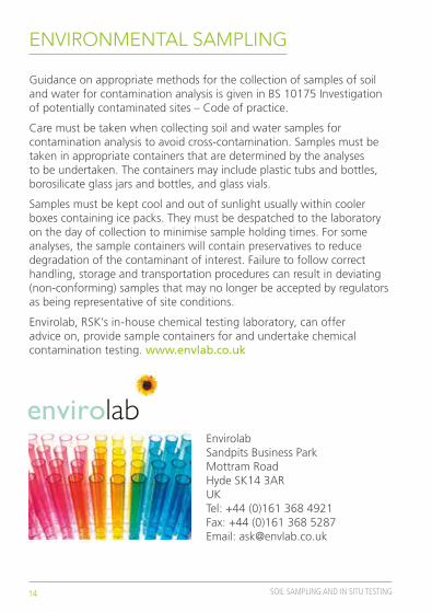
ENVIRONMENTAL SAMPLING
Guidance on appropriate methods for the collection of samples of soil and water for contamination analysis is given in BS 10175 Investigation of potentially contaminated sites – Code of practice.
Care must be taken when collecting soil and water samples for contamination analysis to avoid cross-contamination. Samples must be taken in appropriate containers that are determined by the analyses to be undertaken. The containers may include plastic tubs and bottles, borosilicate glass jars and bottles, and glass vials.
Samples must be kept cool and out of sunlight usually within cooler boxes containing ice packs. They must be despatched to the laboratory on the day of collection to minimise sample holding times. For some analyses, the sample containers will contain preservatives to reduce degradation of the contaminant of interest. Failure to follow correct handling, storage and transportation procedures can result in deviating (non-conforming) samples that may no longer be accepted by regulators as being representative of site conditions.
Envirolab, RSK’s in-house chemical testing laboratory, can offer advice on, provide sample containers for and undertake chemical contamination testing. www.envlab.co.uk
EnvirolabSandpits Business ParkMottram RoadHyde SK14 3ARUKTel: +44 (0)161 368 4921Fax: +44 (0)161 368 5287Email: [email protected]
15SOIL SAMPLING AND IN SITU TESTING
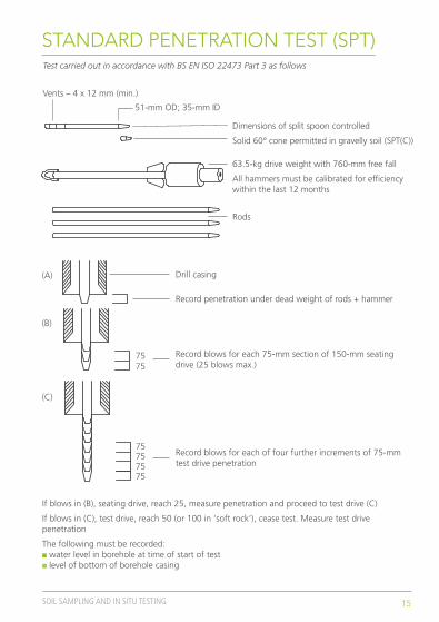
STANDARD PENETRATION TEST (SPT)
Record penetration under dead weight of rods + hammer
Drill casing
Record blows for each 75-mm section of 150-mm seating drive (25 blows max.)
Record blows for each of four further increments of 75-mm test drive penetration
If blows in (B), seating drive, reach 25, measure penetration and proceed to test drive (C)
If blows in (C), test drive, reach 50 (or 100 in ‘soft rock’), cease test. Measure test drive penetration
The following must be recorded:n water level in borehole at time of start of test n level of bottom of borehole casing
75 75
(A)
(B)
(C)
75 75 75 75
Vents – 4 x 12 mm (min.)
51-mm OD; 35-mm ID
Dimensions of split spoon controlled
Solid 60° cone permitted in gravelly soil (SPT(C))
63.5-kg drive weight with 760-mm free fall
All hammers must be calibrated for efficiency within the last 12 months
Rods
Test carried out in accordance with BS EN ISO 22473 Part 3 as follows

16 SOIL SAMPLING AND IN SITU TESTING
SPT CERTIFICATION
Energy losses occur owing to, for example, friction at the hammer (velocity loss compared with the free fall) or during the hammer’s impact on the anvil. Therefore, the energy ratio, Er, of the equipment used has to be known if the N values are going to be used for the quantitative evaluation of foundations or for the comparison of results. A certificate of calibration of the Er-value immediately below the driving head or anvil shall be available.
Example of SPT hammer calibration certificate
© C
opyr
ight
Equ
ipe
Grou
p

17SOIL SAMPLING AND IN SITU TESTING
BOREHOLE TESTING
Borehole vane test
Purpose
To measure the peak and residual in situ shear strength of fine (‘cohesive’) soil within boreholes
Method
The current test method is detailed in BS 1377 Part 9, and is suitable for very soft to firm, intact, saturated fine (‘cohesive’ soil). A vane of cruciform shape is lowered on extension rods to the base of the borehole and pushed at least three borehole diameters into the intact soil beneath. The rods are connected to a calibrated torque measuring instrument at ground level and slowly rotated until sufficient torque is applied to shear the soil under test
Borehole packer permeability test
Purpose
To measure the acceptance in situ by rock of water under pressure, which, in effect, give a measure of permeability
Method
The test method currently in use in the UK is given in BS 22282 part 3. Packers most commonly consist of a rubber duct tube that can be inflated against the side of a borehole using pressurised gas to create a seal within the borehole through which groundwater cannot pass. Water is pumped through the duct into the rock beneath and measurements made of water flow and applied pressure over time. A double packer arrangement can be used to isolate a specific part of a borehole for testing

18 SOIL SAMPLING AND IN SITU TESTING
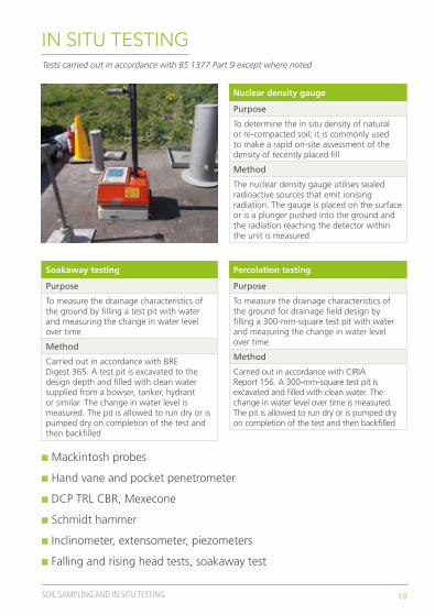
IN SITU TESTING
California bearing ratio (CBR)
Purpose
To measure parameters for the structural design or assessment of pavements and working platforms
Method
Carried out by one technician using small, hand-operated, vehicle-mounted equipment. A hardened steel plunger is inserted into the test surface at a constant rate of penetration and the applied stress is measured
Plate loading test
Purpose
To investigate and test the load-settlement characteristics of a soil
Method
Carried out by one technician using a steel plate and a hydraulic jack. The jack pushes against a kentledge such as the underside of a mechanical excavator. The vertical deformation of the ground under load is assessed by measuring the settlement of the plate over time under different applied loads
Sand replacement test
Purpose
To determine the in situ density of natural or re-compacted soil; it is commonly used to assess the density of recently placed fill
Method
Carried out by one technician using hand-portable, unpowered equipment. A 200-mm-diameter hole is hand excavated to a maximum depth of 250 mm. Dried, graded sand is poured into the hole and the weight of the sand is compared with that of the excavated soil
Tests carried out in accordance with BS 1377 Part 9 except where noted
19SOIL SAMPLING AND IN SITU TESTING
IN SITU TESTING
Nuclear density gauge
Purpose
To determine the in situ density of natural or re-compacted soil; it is commonly used to make a rapid on-site assessment of the density of recently placed fill
Method
The nuclear density gauge utilises sealed radioactive sources that emit ionising radiation. The gauge is placed on the surface or is a plunger pushed into the ground and the radiation reaching the detector within the unit is measured
Soakaway testing
Purpose
To measure the drainage characteristics of the ground by filling a test pit with water and measuring the change in water level over time
Method
Carried out in accordance with BRE Digest 365. A test pit is excavated to the design depth and filled with clean water supplied from a bowser, tanker, hydrant or similar. The change in water level is measured. The pit is allowed to run dry or is pumped dry on completion of the test and then backfilled
Percolation testing
Purpose
To measure the drainage characteristics of the ground for drainage field design by filling a 300-mm-square test pit with water and measuring the change in water level over time
Method
Carried out in accordance with CIRIA Report 156. A 300-mm-square test pit is excavated and filled with clean water. The change in water level over time is measured. The pit is allowed to run dry or is pumped dry on completion of the test and then backfilled
Tests carried out in accordance with BS 1377 Part 9 except where noted
n Mackintosh probes
n Hand vane and pocket penetrometer
n DCP TRL CBR, Mexecone
n Schmidt hammer
n Inclinometer, extensometer, piezometers
n Falling and rising head tests, soakaway test

Soil description
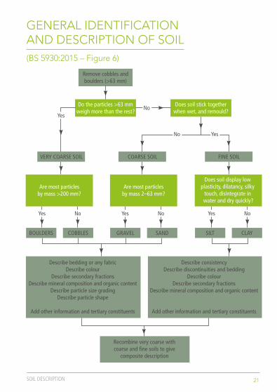
21SOIL DESCRIPTION
GENERAL IDENTIFICATION AND DESCRIPTION OF SOIL(BS 5930:2015 – Figure 6)
Remove cobbles andboulders (>63 mm)
Do the particles >63 mmweigh more than the rest?
Does soil stick togetherwhen wet, and remould?
Does soil display low plasticity, dilatancy, silky
touch, disintegrate in water and dry quickly?
Are most particlesby mass >200 mm?
Are most particlesby mass 2–63 mm?
Describe bedding or any fabricDescribe colour
Describe secondary fractionsDescribe mineral composition and organic content
Describe particle size gradingDescribe particle shape
Add other information and tertiary constituents
Describe consistencyDescribe discontinuities and bedding
Describe colourDescribe secondary fractions
Describe mineral composition and organic content
Add other information and tertiary constituents
Recombine very coarse withcoarse and fine soils to give
composite description
BOULDERS COBBLES GRAVEL SAND SILT CLAY
Yes
Yes No Yes No Yes No
Yes
No
COARSE SOIL FINE SOILVERY COARSE SOIL
No
22 SOIL DESCRIPTION
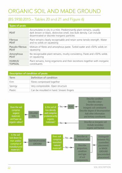
ORGANIC SOIL AND MADE GROUND(BS 5930:2015 – Tables 20 and 21 and Figure 6)
Types of peats
PEATAccumulates in situ in a mire. Predominantly plant remains, usually dark brown or black, distinctive smell, low bulk density. Can include disseminated or discrete inorganic particles
Fibrous PEAT
Plant remains clearly recognisable and retain some tensile strength. Water and no solids on squeezing
Pseudo-fibrous PEAT
Mixture of fibres and amorphous paste. Turbid water and <50% solids on squeezing
Amorphous PEAT
No recognisable plant remains, mushy consistency. Paste and >50% solids on squeezing
HUMUS/ TOPSOIL
Plant remains, living organisms and their excretions together with inorganic constituents
Description of condition of peats
Term Definition of condition
Firm Fibres compressed together
Spongy Very compressible. Open structure
Plastic Can be moulded in hand. Smears fingers
Describe asfor natural soils
Describeproportion,conditionand type
of soilcomponents
Distinguishbetween FILL(controlledplacement)or MADE GROUND
(uncontrolledpleacement)
ANTHROPOGENICGROUND
Is the soil laid down by man and/or comprise of
manufacturedmaterials?
Does soil comprisereworkednatural
material?
Yes
No
PEAT
Describe conditionDescribe colour
Describe secondary inorganic soil constituents
Describe degree of decompositionAdd other information
and tertiary constituents
Describe as inorganic soilInclude secondary
organic soil fraction
ORGANICSOIL
Does the soilcomprise organic
materials and have an
organic odour?
Is the soil oflow density
and comprisepredominantly
organicmaterials?
Yes
No
23SOIL DESCRIPTION
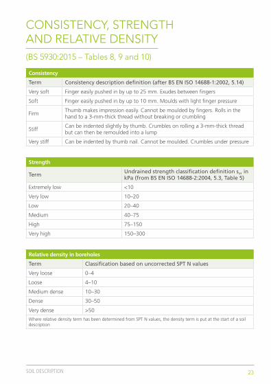
CONSISTENCY, STRENGTH AND RELATIVE DENSITY(BS 5930:2015 – Tables 8, 9 and 10)
Consistency
Term Consistency description definition (after BS EN ISO 14688-1:2002, 5.14)
Very soft Finger easily pushed in by up to 25 mm. Exudes between fingers
Soft Finger easily pushed in by up to 10 mm. Moulds with light finger pressure
FirmThumb makes impression easily. Cannot be moulded by fingers. Rolls in the hand to a 3-mm-thick thread without breaking or crumbling
StiffCan be indented slightly by thumb. Crumbles on rolling a 3-mm-thick thread but can then be remoulded into a lump
Very stiff Can be indented by thumb nail. Cannot be moulded. Crumbles under pressure
Strength
Term Undrained strength classification definition su, in kPa (from BS EN ISO 14688-2:2004, 5.3, Table 5)
Extremely low <10
Very low 10–20
Low 20–40
Medium 40–75
High 75–150
Very high 150–300
Relative density in boreholes
Term Classification based on uncorrected SPT N values
Very loose 0–4
Loose 4–10
Medium dense 10–30
Dense 30–50
Very dense >50
Where relative density term has been determined from SPT N values, the density term is put at the start of a soil description
24 SOIL DESCRIPTION
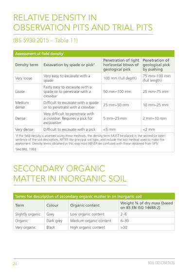
RELATIVE DENSITY IN OBSERVATION PITS AND TRIAL PITS(BS 5930:2015 – Table 11)
SECONDARY ORGANIC MATTER IN INORGANIC SOIL
Assessment of field density1
Density term Excavation by spade or pick2Penetration of light horizontal blows of geological pick
Penetration of geological pick by pushing
Very looseVery easy to excavate with a spade
100 mm (full depth)75 mm–100 mm (full length)
LooseFairly easy to excavate with a spade or to penetrate with a crowbar
50 mm–100 mm 25 mm–75 mm
Medium dense
Difficult to excavate with a spade or to penetrate with a crowbar
25 mm–50 mm 10 mm–25 mm
DenseVery difficult to penetrate with a crowbar. Requires a pick for excavation
5 mm–25 mm 2 mm–10 mm
Very dense Difficult to excavate with a pick <5 mm <2 mm1If the field density is assessed using these methods, the density term MUST be placed in the second (or later) sentence of the soil description, AFTER the principal soil type, and include the test method used to make the assessment. Density terms obtained in this way must NEVER be confused with those obtained from SPTs2See BRE, 1993
Terms for description of secondary organic matter in an inorganic soil
Term Colour Organic content Weight % of dry mass (based on BS EN ISO 14688-2)
Slightly organic Grey Low organic content 2–6
Organic Dark grey Medium organic content 6–30
Very organic Black High organic content >30

25SOIL DESCRIPTION
BEDDING AND STRUCTURE
COLOUR
Bedding and structure
Thickness term Spacing term Thickness or spacing
Very thickly Extremely wide >6 m
Very thickly Very wide 2 m–6 m
Thickly Wide 600 mm–2 m
Medium Medium 200 mm–600 mm
Thinly Close 60 mm–200 mm
Very thinly Very close 20 mm–60 mm
Thickly laminated (sedimentary)
Narrowly (metamorphic and igneous)Extremely close 6 mm–20 mm
Thinly laminated (sedimentary)
Very narrowly (metamorphic and igneous)Extremely close >6 mm
Colour
Lightness (tertiary descriptor)
Chroma (secondary descriptor)
Hue (primary descriptor)
Light
Dark
Reddish
Pinkish
Orangish
Yellowish
Brownish
Greenish
Bluish
Greyish
Red
Pink
Orange
Yellow
Cream
Brown
Green
Blue
White
Grey
Black
The above terms for lightness, chroma and hue may be used in combination for colour description

ODOUR(BS 5930:2015 – Table 19)
Terms for description of odours
Category Descriptive terms
CamphorBitterMothballsAcrid
MuskPenetratingPungent
Floral Wide range of terms, not likely to be used often in made ground
PeppermintSweetMinty
EtherSolventAcetoneMedicinal
Vinegar
SharpAceticPungentRancid
Putrid
Rotten eggRotten cabbageFishyDisagreeable, sweetSulphurous
Hydrocarbon
OrganicPetrolDieselOilAsphaltTar
26 SOIL DESCRIPTION
27SOIL DESCRIPTION
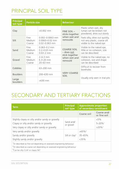
PRINCIPAL SOIL TYPE
SECONDARY AND TERTIARY FRACTIONS
Principal soil type Particle size Behaviour
Clay <0.002 mm FINE SOIL – sticks together when wet and remoulds
Plastic when wet, dry lumps can be broken not powdered, dries out slowly
SiltFine Medium Coarse
0.002–0.0063 mm 0.0063–0.02 mm 0.02–0.063 mm
Feels silky, dries out quickly, not very plastic, coarse silt visible to the naked eye
SandFine Medium Coarse
0.063–0.2 mm 0.2–0.63 mm 0.63–2 mm
COARSE SOIL – does not stick together when wet and remould
Visible to the naked eye, little or no cohesion, size can be described
GravelFine Medium Coarse
2–6.3 mm 6.3–20 mm 20–63 mm
Visible to the naked eye, no cohesion, size and shape can be described
Cobbles 63–200 mm
VERY COARSE SOIL
Difficult to recover from boreholes
Boulders 200–630 mmUsually only seen in trial pitsLarge
boulders >630 mm
Term Principal soil type
Approximate proportion of secondary constituent
Coarse soil Coarse and/or fine soil
Slightly clayey or silty and/or sandy or gravelly
Clayey or silty and/or sandy or gravelly
Very clayey or silty and/or sandy or gravelly
Sand and/or gravel
<5%
5–20%1
>20%1
Very sandy and/or gravelly
Sandy and/or gravelly
Slightly sandy and/or gravelly
Silt or clay3
>65%2
35–65%
<35%1Or described as fine soil depending on assessed engineering behaviour 2Or described as coarse soil depending on assessed engineering behaviour 3Can be silty CLAY or clayey SILT
28 SOIL DESCRIPTION
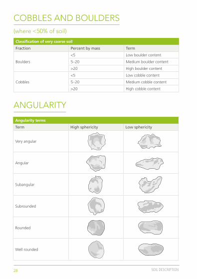
COBBLES AND BOULDERS(where <50% of soil)
ANGULARITY
Classification of very coarse soil
Fraction Percent by mass Term
Boulders
<5 Low boulder content
5–20 Medium boulder content
>20 High boulder content
Cobbles
<5 Low cobble content
5–20 Medium cobble content
>20 High cobble content
Angularity terms
Term High sphericity Low sphericity
Very angular
Angular
Subangular
Subrounded
Rounded
Well rounded
29SOIL DESCRIPTION
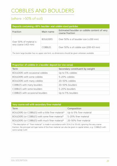
COBBLES AND BOULDERS(where >50% of soil)
Deposits containing >50% boulder- and cobble-sized particles
Fraction Main name Estimated boulder or cobble content of very coarse fraction
Over 50% of material is very coarse (>63 mm)
BOULDERS Over 50% is of boulder size (>200 mm)
COBBLES Over 50% is of cobble size (200–63 mm)
The term large boulder has no upper size limit, so dimensions should be given wherever available
Proportion of cobbles in a boulder deposit (or vice versa)
Term Secondary constituent by weight
BOULDERS with occasional cobbles Up to 5% cobbles
BOULDERS with some cobbles 5–20% cobbles
BOULDERS with many cobbles 20–50% cobbles
COBBLES with many boulders 20–50% boulders
COBBLES with some boulders 5–20% boulders
COBBLES with occasional boulders Up to 5% boulders
Very coarse soil with secondary finer material
Term Composition
BOULDERS (or COBBLES) with a little finer material* Up to 5% finer material
BOULDERS (or COBBLES) with some finer material* 5–20% finer material
BOULDERS (or COBBLES) with much finer material* 20–50% finer material
*The description of “finer material” is made in accordance with 33.4.2 to 33.4.6, ignoring the very coarse fraction; the principal soil type name of the finer material can also be given in capital letters, e.g. COBBLES with some sandy CLAY.

30 SOIL DESCRIPTION
SOIL DESCRIPTION SUMMARY TABLE (PART 1)
Field identification and description of soils (BS 5930:2015, Table 7, part 1) Field identification and description of soils (BS 5930:2015, Table 7, part 2) Field identification and description of soils (BS 5930:2015, Table 7, part 3)
SOIL GROUP Very coarse soils
BOULDERS COBBLESPRINCIPALSOIL TYPE
Large boulder>630
Particle size(mm)
Only seen complete in pits or exposures. Difficult to recover whole from boreholes
VisualID
No terms definedQualitative description of packing byinspection and ease of excavation
Classification of relative density on the basis of N value (Table 10), or field assessment using hand tests may be made (Table 11)
Density/Consistency
Term Very soft Soft
Field test Finger easily pushed inup to 25 mm. Exudesbetween fingers
Finger pushed in up to10 mm. Moulded bylight finger pressure
Term Firm Stiff
Field test
Thumb makes impressioneasily. Cannot be mouldedby fingers. Rolls to thread
Can be indented slightlyby thumb. Crumbles inrolling thread. Remoulds
Very stiff
Describe spacing of features such as fissures, shears, partings, isolated beds orlaminae, desiccation cracks, rootlets, etc.Fissured: Breaks into blocks along unpolished discontinuitiesSheared: Breaks into blocks along polished discontinuities
Scale of spacing of discontinuities
Discontin-uities
Verywidely
Term Widely Medium Closely Veryclosely
Extremely closely
>2000Mean spacing(mm)
2 000–600 600–200 00–60 60–20 <20
Describe thickness of beds in accordance with geological definition.Alternating layers of materials are Inter-bedded or Inter-laminated and should bedescribed by a thickness term if in equal proportions, or by a thickness of andspacing between subordinate layers where unequal
Scale of beddingthickness
Bedding
HUEcan be preceded by LIGHTNESSand/or CHROMA
Light–dark: Red, Pink, Orange, Yellow, Cream, Brown, Green, Blue, White, Grey, Black
Light–dark: Reddish, Pinkish, Orangish, Yellowish, Brownish, Greenish, Bluish, Greyish
Colours may be mottled. More than 3 colours is multicolouredColour
For mixtures involving very coarsesoils see 33.4.4.2
Term in coarse soils
Slightly(sandy) (b)
Sandy (b) Very(sandy) (b)
SAND ANDGRAVEL
Proportionsecondary (a)
<5% 5-20% (c) >20% C ~ 50%
Term in finesoils
Slightly(sandy) (d)
Sandy (d) Very(sandy) (f)
Silty CLAYClayey SILT
Terms used to reflect secondary fine constituents wherethis is important
Proportionsecondary (a)
<35% 35–65% (e) >65% (e)
Secondaryconstituents
Terms can include: glauconitic, micaceous, shelly, organic, calcareous. For example: slightly (glauconitic), (glauconitic), very (glauconitic)
Carbonate content: slightly calcareous – weak or sporadic effervescence from HCI, calcareous – clear but not sustained effervescence from HCI, highly calcareous – strong, sustained effervescence from HCI
Organic soils contain secondary finely divided or discrete particles of organic matter, often with distinctive smell, might oxidize rapidly. For example: slightly organic – grey/organic – dark grey/very organic – black
Mineralogy
Very angular/Angular/Subangular/Subrounded/Rounded/Well-roundedA dominant shape can be described, for example: Cubic/Flat/Elongate
Particle shape
Example terms include: shell fragments, pockets of peat, gypsum crystals, pyrite nodules,calcareous concretions, flint gravel, brick fragments, rootlets, plastic bags
Qualitative proportions can be given: with rare, with occasional, with numerous, frequent, abundant Proportions are defined on a site or material specific basis, or subjectively
As parts 1 and 2Tertiaryconstituents
Name in accordance with published geological maps, memoirs or sheet explanations For example: RIVER TERRACE DEPOSITS, GLACIAL SAND AND GRAVEL, MADE GROUND, LANGLEY SILT MEMBER, WEATHERED CHARMOUTH, MUDSTONE FORMATION, CLAY-WITH-FLINTS
For example: LOWESTOFT FORMATION, EMBANKMENT FILL, ALLUVIUM, TOPSOIL,LAMINATED BEDS, WOOLWICH FORMATION, SHERWOOD SANDSTONE GROUP
Geologicalunit
LARGEBOULDERS
BOULDERS COBBLES GRAVEL SAND SILT CLAYPRINCIPALSOIL TYPE
SOIL GROUP
PRINCIPALSOIL TYPE
Particle size(mm)
VisualID
Density/Consistency
Discontin-uities
Bedding
Colour
Secondaryconstituents
Mineralogy
Tertiaryconstituents
Geologicalunit
PRINCIPALSOIL TYPE
Verythicklybedded
Term Thicklybedded
Mediumbedded
Thinlybedded
Verythinlybedded
Thicklylaminated
>2000Mean thickness (mm)
Term
Mean spacing(mm)
Term
Mean thickness (mm)
2 000–600 600–200 200–60 60–20 20–6
Thinlylaminated
<6
Can be indentedby thumb nail. Cannot be moulded, crumbles
Boulder630–200
Cobble200–63
GRAVEL
Coarse63–20
Easily visible to naked eye;particle shape can be described;grading can be described
Medium20–6.3
Fine6.3–2.0
Coarse soils
SAND
Coarse2.0–0.63
Visible to naked eye;no cohesion when dry;grading can be described
Medium0.63–0.2
Fine0.2–0.063
Coarse soils
SILT
Coarse0.063–0.02
Medium0.02–0.0063
Fine0.0063–0.002
Fine soils
CLAY
<0.002
Fine soils
Notes: a) Percentage coarse or fine soil type assessed excluding cobbles and bouldersb) Gravelly or sandy and/or silty or clayey c) Can be described as fine soil depending on mass behaviour
Notes: d) Gravelly and/or sandy e) Can be described as coarse soil depending on mass behaviourf) Gravelly or sandy
Dry lumps can be broken but not powdered between the fingers; dry lumps disintegrate under water but more slowly than silt; smooth to the touch; exhibits plasticity but no dilatancy; sticks to the fingers and dries slowly; shrinks appreciably on drying usually showing cracks
Only coarse silt visible with hand lens; exhibits little plasticity and marked dilatancy; slightly granular or silky to the touch; disintegrates in water; lumps dry quickly; possesses cohesion but can be powdered easily between fingers
31SOIL DESCRIPTION
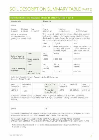
SOIL DESCRIPTION SUMMARY TABLE (PART 2)
Field identification and description of soils (BS 5930:2015, Table 7, part 1) Field identification and description of soils (BS 5930:2015, Table 7, part 2) Field identification and description of soils (BS 5930:2015, Table 7, part 3)
SOIL GROUP Very coarse soils
BOULDERS COBBLESPRINCIPALSOIL TYPE
Large boulder>630
Particle size(mm)
Only seen complete in pits or exposures. Difficult to recover whole from boreholes
VisualID
No terms definedQualitative description of packing byinspection and ease of excavation
Classification of relative density on the basis of N value (Table 10), or field assessment using hand tests may be made (Table 11)
Density/Consistency
Term Very soft Soft
Field test Finger easily pushed inup to 25 mm. Exudesbetween fingers
Finger pushed in up to10 mm. Moulded bylight finger pressure
Term Firm Stiff
Field test
Thumb makes impressioneasily. Cannot be mouldedby fingers. Rolls to thread
Can be indented slightlyby thumb. Crumbles inrolling thread. Remoulds
Very stiff
Describe spacing of features such as fissures, shears, partings, isolated beds orlaminae, desiccation cracks, rootlets, etc.Fissured: Breaks into blocks along unpolished discontinuitiesSheared: Breaks into blocks along polished discontinuities
Scale of spacing of discontinuities
Discontin-uities
Verywidely
Term Widely Medium Closely Veryclosely
Extremely closely
>2000Mean spacing(mm)
2 000–600 600–200 00–60 60–20 <20
Describe thickness of beds in accordance with geological definition.Alternating layers of materials are Inter-bedded or Inter-laminated and should bedescribed by a thickness term if in equal proportions, or by a thickness of andspacing between subordinate layers where unequal
Scale of beddingthickness
Bedding
HUEcan be preceded by LIGHTNESSand/or CHROMA
Light–dark: Red, Pink, Orange, Yellow, Cream, Brown, Green, Blue, White, Grey, Black
Light–dark: Reddish, Pinkish, Orangish, Yellowish, Brownish, Greenish, Bluish, Greyish
Colours may be mottled. More than 3 colours is multicolouredColour
For mixtures involving very coarsesoils see 33.4.4.2
Term in coarse soils
Slightly(sandy) (b)
Sandy (b) Very(sandy) (b)
SAND ANDGRAVEL
Proportionsecondary (a)
<5% 5-20% (c) >20% C ~ 50%
Term in finesoils
Slightly(sandy) (d)
Sandy (d) Very(sandy) (f)
Silty CLAYClayey SILT
Terms used to reflect secondary fine constituents wherethis is important
Proportionsecondary (a)
<35% 35–65% (e) >65% (e)
Secondaryconstituents
Terms can include: glauconitic, micaceous, shelly, organic, calcareous. For example: slightly (glauconitic), (glauconitic), very (glauconitic)
Carbonate content: slightly calcareous – weak or sporadic effervescence from HCI, calcareous – clear but not sustained effervescence from HCI, highly calcareous – strong, sustained effervescence from HCI
Organic soils contain secondary finely divided or discrete particles of organic matter, often with distinctive smell, might oxidize rapidly. For example: slightly organic – grey/organic – dark grey/very organic – black
Mineralogy
Very angular/Angular/Subangular/Subrounded/Rounded/Well-roundedA dominant shape can be described, for example: Cubic/Flat/Elongate
Particle shape
Example terms include: shell fragments, pockets of peat, gypsum crystals, pyrite nodules,calcareous concretions, flint gravel, brick fragments, rootlets, plastic bags
Qualitative proportions can be given: with rare, with occasional, with numerous, frequent, abundant Proportions are defined on a site or material specific basis, or subjectively
As parts 1 and 2Tertiaryconstituents
Name in accordance with published geological maps, memoirs or sheet explanations For example: RIVER TERRACE DEPOSITS, GLACIAL SAND AND GRAVEL, MADE GROUND, LANGLEY SILT MEMBER, WEATHERED CHARMOUTH, MUDSTONE FORMATION, CLAY-WITH-FLINTS
For example: LOWESTOFT FORMATION, EMBANKMENT FILL, ALLUVIUM, TOPSOIL,LAMINATED BEDS, WOOLWICH FORMATION, SHERWOOD SANDSTONE GROUP
Geologicalunit
LARGEBOULDERS
BOULDERS COBBLES GRAVEL SAND SILT CLAYPRINCIPALSOIL TYPE
SOIL GROUP
PRINCIPALSOIL TYPE
Particle size(mm)
VisualID
Density/Consistency
Discontin-uities
Bedding
Colour
Secondaryconstituents
Mineralogy
Tertiaryconstituents
Geologicalunit
PRINCIPALSOIL TYPE
Verythicklybedded
Term Thicklybedded
Mediumbedded
Thinlybedded
Verythinlybedded
Thicklylaminated
>2000Mean thickness (mm)
Term
Mean spacing(mm)
Term
Mean thickness (mm)
2 000–600 600–200 200–60 60–20 20–6
Thinlylaminated
<6
Can be indentedby thumb nail. Cannot be moulded, crumbles
Boulder630–200
Cobble200–63
GRAVEL
Coarse63–20
Easily visible to naked eye;particle shape can be described;grading can be described
Medium20–6.3
Fine6.3–2.0
Coarse soils
SAND
Coarse2.0–0.63
Visible to naked eye;no cohesion when dry;grading can be described
Medium0.63–0.2
Fine0.2–0.063
Coarse soils
SILT
Coarse0.063–0.02
Medium0.02–0.0063
Fine0.0063–0.002
Fine soils
CLAY
<0.002
Fine soils
Notes: a) Percentage coarse or fine soil type assessed excluding cobbles and bouldersb) Gravelly or sandy and/or silty or clayey c) Can be described as fine soil depending on mass behaviour
Notes: d) Gravelly and/or sandy e) Can be described as coarse soil depending on mass behaviourf) Gravelly or sandy
Dry lumps can be broken but not powdered between the fingers; dry lumps disintegrate under water but more slowly than silt; smooth to the touch; exhibits plasticity but no dilatancy; sticks to the fingers and dries slowly; shrinks appreciably on drying usually showing cracks
Only coarse silt visible with hand lens; exhibits little plasticity and marked dilatancy; slightly granular or silky to the touch; disintegrates in water; lumps dry quickly; possesses cohesion but can be powdered easily between fingers

32 SOIL DESCRIPTION
SOIL DESCRIPTION SUMMARY TABLE (PART 3)
Field identification and description of soils (BS 5930:2015, Table 7, part 1) Field identification and description of soils (BS 5930:2015, Table 7, part 2) Field identification and description of soils (BS 5930:2015, Table 7, part 3)
SOIL GROUP Very coarse soils
BOULDERS COBBLESPRINCIPALSOIL TYPE
Large boulder>630
Particle size(mm)
Only seen complete in pits or exposures. Difficult to recover whole from boreholes
VisualID
No terms definedQualitative description of packing byinspection and ease of excavation
Classification of relative density on the basis of N value (Table 10), or field assessment using hand tests may be made (Table 11)
Density/Consistency
Term Very soft Soft
Field test Finger easily pushed inup to 25 mm. Exudesbetween fingers
Finger pushed in up to10 mm. Moulded bylight finger pressure
Term Firm Stiff
Field test
Thumb makes impressioneasily. Cannot be mouldedby fingers. Rolls to thread
Can be indented slightlyby thumb. Crumbles inrolling thread. Remoulds
Very stiff
Describe spacing of features such as fissures, shears, partings, isolated beds orlaminae, desiccation cracks, rootlets, etc.Fissured: Breaks into blocks along unpolished discontinuitiesSheared: Breaks into blocks along polished discontinuities
Scale of spacing of discontinuities
Discontin-uities
Verywidely
Term Widely Medium Closely Veryclosely
Extremely closely
>2000Mean spacing(mm)
2 000–600 600–200 00–60 60–20 <20
Describe thickness of beds in accordance with geological definition.Alternating layers of materials are Inter-bedded or Inter-laminated and should bedescribed by a thickness term if in equal proportions, or by a thickness of andspacing between subordinate layers where unequal
Scale of beddingthickness
Bedding
HUEcan be preceded by LIGHTNESSand/or CHROMA
Light–dark: Red, Pink, Orange, Yellow, Cream, Brown, Green, Blue, White, Grey, Black
Light–dark: Reddish, Pinkish, Orangish, Yellowish, Brownish, Greenish, Bluish, Greyish
Colours may be mottled. More than 3 colours is multicolouredColour
For mixtures involving very coarsesoils see 33.4.4.2
Term in coarse soils
Slightly(sandy) (b)
Sandy (b) Very(sandy) (b)
SAND ANDGRAVEL
Proportionsecondary (a)
<5% 5-20% (c) >20% C ~ 50%
Term in finesoils
Slightly(sandy) (d)
Sandy (d) Very(sandy) (f)
Silty CLAYClayey SILT
Terms used to reflect secondary fine constituents wherethis is important
Proportionsecondary (a)
<35% 35–65% (e) >65% (e)
Secondaryconstituents
Terms can include: glauconitic, micaceous, shelly, organic, calcareous. For example: slightly (glauconitic), (glauconitic), very (glauconitic)
Carbonate content: slightly calcareous – weak or sporadic effervescence from HCI, calcareous – clear but not sustained effervescence from HCI, highly calcareous – strong, sustained effervescence from HCI
Organic soils contain secondary finely divided or discrete particles of organic matter, often with distinctive smell, might oxidize rapidly. For example: slightly organic – grey/organic – dark grey/very organic – black
Mineralogy
Very angular/Angular/Subangular/Subrounded/Rounded/Well-roundedA dominant shape can be described, for example: Cubic/Flat/Elongate
Particle shape
Example terms include: shell fragments, pockets of peat, gypsum crystals, pyrite nodules,calcareous concretions, flint gravel, brick fragments, rootlets, plastic bags
Qualitative proportions can be given: with rare, with occasional, with numerous, frequent, abundant Proportions are defined on a site or material specific basis, or subjectively
As parts 1 and 2Tertiaryconstituents
Name in accordance with published geological maps, memoirs or sheet explanations For example: RIVER TERRACE DEPOSITS, GLACIAL SAND AND GRAVEL, MADE GROUND, LANGLEY SILT MEMBER, WEATHERED CHARMOUTH, MUDSTONE FORMATION, CLAY-WITH-FLINTS
For example: LOWESTOFT FORMATION, EMBANKMENT FILL, ALLUVIUM, TOPSOIL,LAMINATED BEDS, WOOLWICH FORMATION, SHERWOOD SANDSTONE GROUP
Geologicalunit
LARGEBOULDERS
BOULDERS COBBLES GRAVEL SAND SILT CLAYPRINCIPALSOIL TYPE
SOIL GROUP
PRINCIPALSOIL TYPE
Particle size(mm)
VisualID
Density/Consistency
Discontin-uities
Bedding
Colour
Secondaryconstituents
Mineralogy
Tertiaryconstituents
Geologicalunit
PRINCIPALSOIL TYPE
Verythicklybedded
Term Thicklybedded
Mediumbedded
Thinlybedded
Verythinlybedded
Thicklylaminated
>2000Mean thickness (mm)
Term
Mean spacing(mm)
Term
Mean thickness (mm)
2 000–600 600–200 200–60 60–20 20–6
Thinlylaminated
<6
Can be indentedby thumb nail. Cannot be moulded, crumbles
Boulder630–200
Cobble200–63
GRAVEL
Coarse63–20
Easily visible to naked eye;particle shape can be described;grading can be described
Medium20–6.3
Fine6.3–2.0
Coarse soils
SAND
Coarse2.0–0.63
Visible to naked eye;no cohesion when dry;grading can be described
Medium0.63–0.2
Fine0.2–0.063
Coarse soils
SILT
Coarse0.063–0.02
Medium0.02–0.0063
Fine0.0063–0.002
Fine soils
CLAY
<0.002
Fine soils
Notes: a) Percentage coarse or fine soil type assessed excluding cobbles and bouldersb) Gravelly or sandy and/or silty or clayey c) Can be described as fine soil depending on mass behaviour
Notes: d) Gravelly and/or sandy e) Can be described as coarse soil depending on mass behaviourf) Gravelly or sandy
Dry lumps can be broken but not powdered between the fingers; dry lumps disintegrate under water but more slowly than silt; smooth to the touch; exhibits plasticity but no dilatancy; sticks to the fingers and dries slowly; shrinks appreciably on drying usually showing cracks
Only coarse silt visible with hand lens; exhibits little plasticity and marked dilatancy; slightly granular or silky to the touch; disintegrates in water; lumps dry quickly; possesses cohesion but can be powdered easily between fingers

33SOIL DESCRIPTION
WORD ORDER AND EXAMPLE DESCRIPTIONS
General soil description – word order (BS 5930:2015)Note: Tables and clause numbers referred to below are those in BS 5930:2015
A. Mass characteristics comprising state and structure (see 33.3):1) relative density/consistency;2) discontinuities;3) bedding;
B. Material characteristics comprising nature and state (see 33.4);1) colour;2) composite soil types: particle grading and composition; shape and size;3) tertiary constituents either before or after the principal soil type as appropriate;4) principal soil type (name in capitals, e.g. SAND), based on grading and plasticity shape;
C. Stratum name: geological formation, age and type of deposit (see 33.5); classification (optional)
RSK company approach1. All terms describing particle shape and size go after the principal soil
type, after the full stop
2. Secondary and tertiary size fractions are listed in order of particle size, not proportion; for example, in ‘silty sandy slightly gravelly CLAY’, the term ‘sandy’ will always occur before ‘gravelly’ no matter how much of each there is
3. Topsoil should generally be described as a normal soil and the word should be (TOPSOIL) added in brackets at the end of the description

34 SOIL DESCRIPTION
WORD ORDER AND EXAMPLE DESCRIPTIONS
Example descriptions
A. MADE GROUND: Firm brown slightly sandy gravelly CLAY. Sand is fine to coarse. Gravel is angular fine to coarse brick and concrete fragments. Occasional pieces of wire, rubber and plastic
B. Stiff orangish brown silty slightly sandy CLAY. Occasional rootlets. (TOPSOIL)
C. Plastic dark brown clayey PEAT. Strong (natural organic?) odour
D. Very stiff extremely closely fissured brown mottled red and grey silty CLAY with a low cobble content. Cobbles are tabular angular of mudstone up to 100 mm across
E. Dense multicoloured (grey, white, orange and brown) very clayey very sandy GRAVEL. Sand is fine to coarse. Gravel is well rounded to subrounded fine to medium flint
F. Grey COBBLES with occasional boulders and much sandy GRAVEL. Sand is coarse. Gravel is subangular fine to coarse of sandstone. Cobbles and boulders are angular up to 400 mm across of sandstone
G. Firm closely fissured yellowish brown CLAY (LONDON CLAY FORMATION)
H. Medium dense light greyish brown slightly clayey sandy GRAVEL with a low cobble content. Sand is fine to coarse. Gravel is subrounded fine to coarse of mixed lithologies. Cobbles are subrounded of strong sandstone. (RIVER TERRACE DEPOSITS)
I. Greenish brown gravelly slightly glauconitic SAND. Sand is fine to coarse. Gravel is rounded fine to medium of black flint. Assessed as loose as fairly easy to excavate with a spade. (HARWICH FORMATION – BLACKHEATH MEMBER).
J. Firm to stiff brown slightly sandy slightly gravelly CLAY with occasional lenses (5 mm by 15 mm to 15 mm by 50 mm) of yellow silty sand. Gravel is subangular to subrounded fine and medium of various lithologies (GLACIAL TILL)
Rock description
36 ROCK DESCRIPTION
ROCK DESCRIPTION
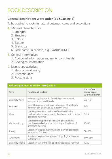
General description: word order (BS 5930:2015)
To be applied to rocks in natural outcrops, cores and excavations
A. Material characteristics:1. Strength2. Structure3. Colour4. Texture5. Grain size6. Rock name (in capitals, e.g., SANDSTONE)
B. General information:1. Additional information and minor constituents2. Geological information
C. Mass characteristics:1. State of weathering2. Discontinuities3. Fracture state
Rock strengths from BS EN ISO 14689 (table 5)
Term Field identificationUnconfined compressive strength (MPa)
Extremely weakIndented by thumbnail. Gravel sized lumps crush between finger and thumb
0.6–1.0
Very weakCrumbles under firm blows with points of geological hammer; can be peeled by a pocket knife
1–5
WeakCan be peeled by a pocket knife with difficulty; shallow indentations made by firm blows with point of geological hammer
5–25
Medium strongCannot be scraped or peeled with pocket knife; specimen can be fractured with single firm blow of geological hammer
25–50
StrongSpecimen requires more than one blow of geological hammer to fracture it
50–100
Very strongSpecimen requires many blows of geological hammer to fracture it
100–250
Extremely strong Specimen can only be chipped by geological hammer >250
37ROCK DESCRIPTION
ROCK DESCRIPTION
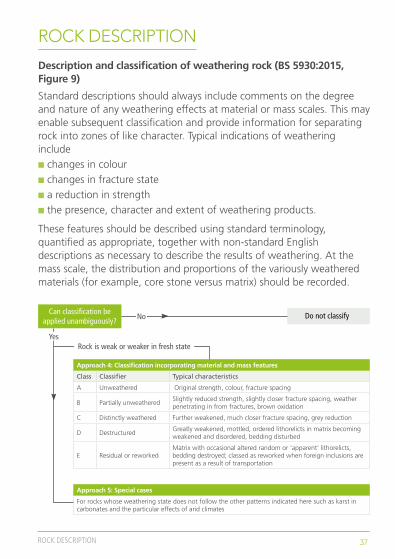
Description and classification of weathering rock (BS 5930:2015, Figure 9)
Standard descriptions should always include comments on the degree and nature of any weathering effects at material or mass scales. This may enable subsequent classification and provide information for separating rock into zones of like character. Typical indications of weathering includen changes in colourn changes in fracture staten a reduction in strengthn the presence, character and extent of weathering products.
These features should be described using standard terminology, quantified as appropriate, together with non-standard English descriptions as necessary to describe the results of weathering. At the mass scale, the distribution and proportions of the variously weathered materials (for example, core stone versus matrix) should be recorded.
Approach 4: Classification incorporating material and mass features
Class Classifier Typical characteristics
A Unweathered Original strength, colour, fracture spacing
B Partially unweatheredSlightly reduced strength, slightly closer fracture spacing, weather penetrating in from fractures, brown oxidation
C Distinctly weathered Further weakened, much closer fracture spacing, grey reduction
D DestructuredGreatly weakened, mottled, ordered lithorelicts in matrix becoming weakened and disordered, bedding disturbed
E Residual or reworkedMatrix with occasional altered random or ‘apparent’ lithorelicts, bedding destroyed; classed as reworked when foreign inclusions are present as a result of transportation
Approach 5: Special cases
For rocks whose weathering state does not follow the other patterns indicated here such as karst in carbonates and the particular effects of arid climates
Do not classifyCan classification beapplied unambiguously?
Rock is weak or weaker in fresh state
No
Yes

38 ROCK DESCRIPTION
ROCK DESCRIPTION (PART 1)
Sedimentary rocks Granular cemented rocks vary greatly in strength, some sandstones are stronger than many igneous rocks. Bedding may not show in hand specimens and is best seen in outcrop. Only sedimentary rocks, and some metamorphic rocks derived from them, contain fossils.
Calcareous rocks contain calcite (calcium carbonate), which effervesces with dilute hydrochloric acid.
Grain size(mm) Bedded rocks (mostly sedimentary)
Grain sizedescription
CONGLOMERATERounded boulderscobbles and gravelcemented in a finermatrixBrecciaIrregular rockfragments in afiner matrix
SANDSTONEAngular or roundedgrains commonlycemented by clay,calcite or iron mineralsQuartziteQuartz grains andsiliceous cementArkoseMany feldspar grainsGreywackeMany rock chips
SILTSTONEMostly silt
MUDSTONE
Calcisiltite
Calcilutite
At least 50% of grainsare of carbonate
At least 50% of grains are of grainedvolcanic rock
Fragments of volcanic ejects in a finer matrixRounded grainsAGGLOMERATEAngular grainsVOLCANICBRECCIA
Calcirudite
20
Gra
in s
ize
boun
darie
s ap
prox
imat
e
ARE
NA
CEO
US
RUD
AC
EOU
S
LIM
ESTO
NE
and
DO
LERI
TE (u
ndiff
eren
tiate
d)
ARG
ILLA
CEO
US
CH
ALK
Cal
care
ous
mud
ston
e
Fine
Med
ium
Coa
rse Cemented
volcanic ashCalcarenite
TUFF
Fine-grained TUFF
Very fine-grained TUFF
HALITE
CARBONACEOUSSILICEOUSCALCAREOUSSILICEOUS
COALLIGNITE
Flint: occurs as bands of nodules in the chalkChert: occurs as nodules and beds in limestoneand calcareous sandstoneGranular cemented – except amorphous rocks
Amorphousor crypto-crystalline
GYPSUM
ANHYDRITE
SALINEROCKS
6.3
2
0.63
0.2
0.063
0.002
Description of rock (tables on pages 137–138 from BS 5930, Table 27)

39ROCK DESCRIPTION
ROCK DESCRIPTION (PART 2)
Grain sizedescription
Foliated
GNEISSWell-developed butoften widely spacedfoliation sometimeswith schistose bandsMigmatiteIrregular foliated:mixed schists andgneisses
MARBLE
QUARTZITE
GRANULITE
HORNFELS
AMPHIBOLITE
SERPENTINE
CRYSTALLINE
SILICEOUS MainlySILICEOUS
SCHISTWell-developed undulose foliation:generally much mica
PHYLLITESlightly undulosefoliation; sometimesspottedSLATEWell-developed plane cleavage (foliation)MYLONITEFound in fault zones,mainly in igneous and metamorphicareas
Massive
COARSE
Perido-tite
Incr
easi
ng g
rain
siz
ePyroxe-nite
These rocks are sometimes porphyritic and are then described, for example, as porphyritic granite
These rocks are sometimes porphyritic and are then described as porphyries
GABBRO1,2DIORITE1,2GRANITE1
MEDIUM
DOLERITE3,4MICRO-DIORITE1,2
MICRO-GRANITE1
These rocks are sometimes porphyritic and are then described as porphyries
Amorphous orcrypto-crystalline
PaleACID(much quartz)
INTER-MEDIATE(some quartz)
BASIC(Little orno quartz)
ULTRABASIC
DarkColour
FINE
BASALT5ANDESITE4,5RHYOLITE4,5
OBSIDIAN5 VOLCANIC GLASS
Igneous rocks: generally massive structure and crystalline texture Metamorphic rocks
Igneous rocksComposed of closely interlocking mineral grains, strong when fresh, not porous. Occurrence: 1. batholiths, 2. laccoliths, 3. sills, 4. dykes, 5. lava flows, 6. veins.
Metamorphic rocksGenerally classified according to fabric and mineralogy rather than grain size. Most metamorphic rocks are distinguished by foliation, which may impart fissility. Foliation in gneisses is best observed in outcrop. Non-foliated metamorphics are difficult to recognise except by association. Most fresh metamorphic rocks are strong but fissile.

40 ROCK DESCRIPTION
ROCK DESCRIPTION (PART 1)
Type oftermination
Discontinuity spacingOrientation Persistence Roughness
Terminology and checklist for rock discontinuity description (BS 5930:2015, Table 30)
Dip amount onlyin cores
Take number ofreadings of dipdirection/dip e.g. 015/18˚
Report as rangeand on stereo netif appropriate
Extremely wide>6 m
Discontinuous
Termination
Cannot normallybe describedin cores
Stepped
Rough
Smooth
Striated
Rough
Smooth
Rough
Waviness
Curvature
Straightness
Smooth
Striated
Striated
Undulating
Large scale (m)
Planar
Measures amplitudeand wavelength offeature
Intermediatescale (cm) andsmall scale (mm)
x (outsideexposure)
r (within rock)
d (againstdiscontinuity)
Record alsosize ofdiscontinuity
Continuousin cores
Very high>20 m
High10 m–20 m
Medium3 m–10 m
Low1 m–3 m
Very low1<m
Very wide2–6 m
Wide600 mm–2 m
Medium200 mm–600 mm
Close60 mm–200 mm
Very close20 mm–60 mm
Extremely close<20 mm
Take number ofreadings andstate minimum,mode and maximum.
ApetureWall strength Filing Seepage Number of sets
Terminology and checklist for rock discontinuity description (BS 5930:2015, Table 30)
Schmidthammer
Point load test
Other index tests
Visual assessment
Cannot normallybe described incores
Extremely wide>1 m
Open0.5 mm–2.5 mm
Very tight<0.1 mm
Mineral coatings(e.g. calcitechlorite, gypsum etc.)
Surfacestaining (colour)
Soil infilling(described inaccordancewith Clause 33)
Clean
Cannot bedescribed incores
Can bedescribed orsummarised incores where setsof different dipare present
Record orientationand spacing of sets to eachother and alldetails for eachset
Water flowmeasured pertime unit on anindividualdiscontinuity orset ofdiscontinuities
Medium flow0.5 l/s–5 l/s
Small flow0.05 l/s–0.5 l/s
Large flow>5 l/s
Moisture onrock surfaces
Drippingwater
Other (specify)
Record widthand continuityof infill
Tight0.1 mm–0.25 mm
Partly open0.25 mm–2.5 mm
Moderately wide2.5 mm–10 mm
Wide0.01 m–0.1 m
Very wide0.1 m–1 m
41ROCK DESCRIPTION
ROCK DESCRIPTION (PART 2)
Type oftermination
Discontinuity spacingOrientation Persistence Roughness
Terminology and checklist for rock discontinuity description (BS 5930:2015, Table 30)
Dip amount onlyin cores
Take number ofreadings of dipdirection/dip e.g. 015/18˚
Report as rangeand on stereo netif appropriate
Extremely wide>6 m
Discontinuous
Termination
Cannot normallybe describedin cores
Stepped
Rough
Smooth
Striated
Rough
Smooth
Rough
Waviness
Curvature
Straightness
Smooth
Striated
Striated
Undulating
Large scale (m)
Planar
Measures amplitudeand wavelength offeature
Intermediatescale (cm) andsmall scale (mm)
x (outsideexposure)
r (within rock)
d (againstdiscontinuity)
Record alsosize ofdiscontinuity
Continuousin cores
Very high>20 m
High10 m–20 m
Medium3 m–10 m
Low1 m–3 m
Very low1<m
Very wide2–6 m
Wide600 mm–2 m
Medium200 mm–600 mm
Close60 mm–200 mm
Very close20 mm–60 mm
Extremely close<20 mm
Take number ofreadings andstate minimum,mode and maximum.
ApetureWall strength Filing Seepage Number of sets
Terminology and checklist for rock discontinuity description (BS 5930:2015, Table 30)
Schmidthammer
Point load test
Other index tests
Visual assessment
Cannot normallybe described incores
Extremely wide>1 m
Open0.5 mm–2.5 mm
Very tight<0.1 mm
Mineral coatings(e.g. calcitechlorite, gypsum etc.)
Surfacestaining (colour)
Soil infilling(described inaccordancewith Clause 33)
Clean
Cannot bedescribed incores
Can bedescribed orsummarised incores where setsof different dipare present
Record orientationand spacing of sets to eachother and alldetails for eachset
Water flowmeasured pertime unit on anindividualdiscontinuity orset ofdiscontinuities
Medium flow0.5 l/s–5 l/s
Small flow0.05 l/s–0.5 l/s
Large flow>5 l/s
Moisture onrock surfaces
Drippingwater
Other (specify)
Record widthand continuityof infill
Tight0.1 mm–0.25 mm
Partly open0.25 mm–2.5 mm
Moderately wide2.5 mm–10 mm
Wide0.01 m–0.1 m
Very wide0.1 m–1 m
42 ROCK DESCRIPTION
ROCK DESCRIPTION
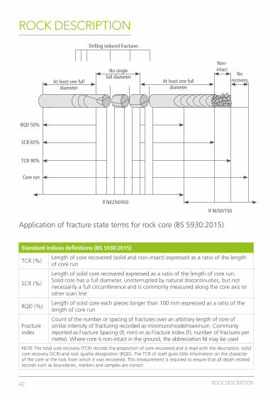
Standard indices definitions (BS 5930:2015)
TCR (%)Length of core recovered (solid and non-intact) expressed as a ratio of the length of core run
SCR (%)
Length of solid core recovered expressed as a ratio of the length of core run. Solid core has a full diameter, uninterrupted by natural discontinuities, but not necessarily a full circumference and is commonly measured along the core axis or other scan line
RQD (%)Length of solid core each pieces longer than 100 mm expressed as a ratio of the length of core run
Fracture index
Count of the number or spacing of fractures over an arbitrary length of core of similar intensity of fracturing recorded as minimum/mode/maximum. Commonly reported as Fracture Spacing (If, mm) or as Fracture Index (FI, number of fractures per metre). Where core is non-intact in the ground, the abbreviation NI may be used
NOTE The total core recovery (TCR) records the proportion of core recovered and is read with the description, solid core recovery (SCR) and rock quality designation (RQD). The TCR of itself gives little information on the character of the core or the rock from which it was recovered. This measurement is required to ensure that all depth related records such as boundaries, markers and samples are correct
RQD 50%
SCR 65%
Drilling induced fractures
At least one fulldiameter
No singlefull diameter
At least one fulldiameter
Non-intact
Norecovery
TCR 90%
Core run
If NI/250/450
If NI/50/150
Application of fracture state terms for rock core (BS 5930:2015)

43ROCK DESCRIPTION
Is c
halk
str
uctu
rele
ss: a
mel
ange
of fi
nes
and
inta
ct c
halk
lum
ps w
ith re
gula
ror
ient
atio
n of
bed
ding
or d
isco
ntin
uity
?
Fine
soi
l beh
avio
ur, i
.e.
com
min
uted
cha
lkm
atrix
> 3
5%
No
Yes
Asse
ss d
isco
ntin
uity
spa
cing
Gra
de D
c
Dens
itysc
ale
Low
den
sity
30–4
0-m
m-th
ickfra
gmen
ts c
rush
by
finge
r pre
ssur
e an
d re
mou
ld to
put
ty
30–4
0-m
m-th
ickfra
gmen
ts b
reak
with
both
han
ds: w
ill n
otcr
ush
with
fing
erpr
essu
re
Cann
ot b
reak
30–
40-m
m-
thick
frag
men
ts in
two:
diffi
cult
to b
reak
slabs
<10
mm
thick
and
corn
ers/
edge
s of
lum
ps
Unab
le to
bre
ak b
yha
nd: 1
00-m
m-d
iam
eter
lum
p he
ld in
han
d br
oken
by s
ingl
e ha
mm
er b
low
Brea
king
by
hand
Pene
tratin
g (m
m) w
ith:
150
mm
nail
>25
>30
>35
15–2
511
–30
18–3
5
6–15
2–11
6–18
<6
<2
<6
Used
ham
mer
pick
New
ham
mer
pick
Med
ium
dens
ity
High
den
sity
Very
hig
h de
nsity
Typi
cal
disc
ontin
uity
aper
ture
Gra
des A
, B o
r C
Labo
rato
ryde
term
inat
ion
ofin
tact
dry
den
sity
t>60
0 m
m20
0<t<
600
mm
60<
t<20
0 m
m20
<t<
60 m
mt<
20 m
m
1 2 3 4 5
Typi
cal
disc
ontin
uity
spac
ing
Suffi
x 1,
2, 3
, 4 o
r 5G
rade
Dm
Asse
ss d
isco
ntin
uity
ape
rtur
e
Typi
cal d
isco
ntin
uity
ape
rtur
eG
rade
Typi
cal d
isco
ntin
uity
spa
cing
Suffi
x
No
infil
l
Infil
led
<3
mm
Infil
led
>3
mm
Clos
ed
Ope
n or
infil
led
<3
mm
Ope
n or
infil
led
>3
mm
A B C
Whe
n lo
ggin
gbo
reho
leW
hen
logg
ing
in s
itu
Fiel
d id
entifi
catio
nDe
nsity
sca
le
Asse
ss in
tact
dry
den
sity
No
Yes
CHALK DESCRIPTIONSource: CIRIA Report C574 Engineering in chalk (2002), Part 4
44 ROCK DESCRIPTION
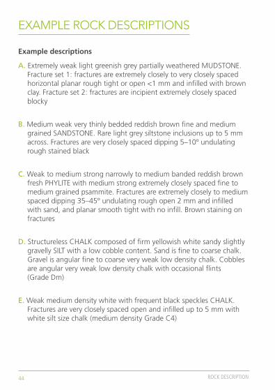
EXAMPLE ROCK DESCRIPTIONS
Example descriptions
A. Extremely weak light greenish grey partially weathered MUDSTONE. Fracture set 1: fractures are extremely closely to very closely spaced horizontal planar rough tight or open <1 mm and infilled with brown clay. Fracture set 2: fractures are incipient extremely closely spaced blocky
B. Medium weak very thinly bedded reddish brown fine and medium grained SANDSTONE. Rare light grey siltstone inclusions up to 5 mm across. Fractures are very closely spaced dipping 5–10º undulating rough stained black
C. Weak to medium strong narrowly to medium banded reddish brown fresh PHYLITE with medium strong extremely closely spaced fine to medium grained psammite. Fractures are extremely closely to medium spaced dipping 35–45º undulating rough open 2 mm and infilled with sand, and planar smooth tight with no infill. Brown staining on fractures
D. Structureless CHALK composed of firm yellowish white sandy slightly gravelly SILT with a low cobble content. Sand is fine to coarse chalk. Gravel is angular fine to coarse very weak low density chalk. Cobbles are angular very weak low density chalk with occasional flints (Grade Dm)
E. Weak medium density white with frequent black speckles CHALK. Fractures are very closely spaced open and infilled up to 5 mm with white silt size chalk (medium density Grade C4)
Laboratory testing

46 LABORATORY TESTING
LABORATORY TESTING (PART 1)
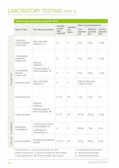
Guide to basic laboratory testing (BS 1377)
Type of test Derived parameters
Suitable sample type required
Suitable soil types
Mass required based on
Fine grained soil
Medium grained soil
Coarse grained soil
Cla
ssifi
cati
on
tes
ts
Moisture content Moisture content D, U C, S, G 50 g 350 g 4 kg
Atterberg limits (LL/LP)
Liquid limit (%)
Plastic limit (%)
Plasticity index (%)
D, U C, S 500 g 1 kg 2 kg
Density (linear)
Density (mg/m3) U C, S 500 g 1 kg 2 kg
Particle size description (PSD)
Particle size distribution by weight
D, B All 150 g 3 kg 17 kg
Co
mp
acti
on
tes
ts
California bearing ratio (CBR) CBR value U*, B All 6 kg 6 kg 12 kg
Compaction (heavy/4.5 kg)
Maximum density and optimum moisture content
B All 10 kg 25 kg 50 kg
Compaction (light/2.5 kg) B All 10 kg 25 kg 50 kg
Compaction (vibrating hammer) B All 50 kg 50 kg 50 kg
Fine grained soil = <2 mm (includes clay, silt, sand) U = Undisturbed sample (U100)
Medium grained soil = 2–20 mm (includes fine and medium) B = Bulk disturbed sample
Coarse grained soil = 20–75 mm (includes coarse gravel) D = Small disturbed sample
47LABORATORY TESTING
LABORATORY TESTING (PART 2)
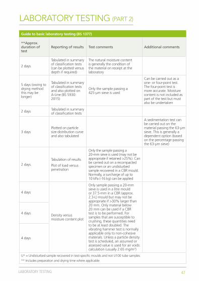
Guide to basic laboratory testing (BS 1377)
**Approx. duration of test
Reporting of results Test comments Additional comments
2 days
Tabulated in summary of classification tests (can be plotted versus depth if required)
The natural moisture content is generally the condition of the material on receipt at the laboratory
5 days (owing to drying method this may be longer)
Tabulated in summary of classification tests and also plotted on A-Line (BS 5930: 2015)
Only the sample passing a 425-µm sieve is used
Can be carried out as a one- or four-point test. The four-point test is more accurate. Moisture content is not included as part of the test but must also be undertaken
2 days Tabulated in summary of classification tests
3 daysPlotted on particle size distribution curve and also tabulated
A sedimentation test can be carried out on the material passing the 63-µm sieve. This is generally a dependent option (based on the percentage passing the 63-µm sieve)
2 daysTabulation of results
Plot of load versus penetration
Only the sample passing a 20-mm sieve is used (may not be appropriate if retained >25%). Can be carried out on a recompacted specimen or an undisturbed sample recovered in a CBR mould. Normally, a surcharge of up to 10 kPa (-16 kg) can be applied
4 days
Density versus moisture content plot
Only sample passing a 20-mm sieve is used in a litre mould or 37.5-mm in a CBR (approx. 2.3-L) mould but may not be appropriate if >30% larger than 20 mm. Only material below 20 mm can be used if a CBR test is to be performed. For samples that are susceptible to crushing, these quantities need to be at least doubled. The vibrating hammer test is normally applicable only to non-cohesive materials. Unless a particle density test is scheduled, an assumed or assessed value is used for air voids calculation (usually 2.65 mg/m3)
4 days
4 days
U* = Undisturbed sample recovered in test-specific moulds and not U100 tube samples
** Includes preparation and drying time where applicable
48 LABORATORY TESTING
LABORATORY TESTING (PART 3)
Guide to basic laboratory testing (BS 1377)
Type of test Derived parameters
Suitable sample type required
Suitable soil types
Mass required based on
Fine grained soil
Medium grained soil
Coarse grained soil
Stre
ngth
tes
ts
Undrained unconsolidated triaxial (UU)
Shear strength/ cohesion – cu
U C 6 kg 6 kg 12 kg
Consolidated undrained triaxial (CU)
Effective cohesion, c´
Effective angle of shear resistance, Φ
U C 6 kg 6 kg 12 kg
Consolidated drained triaxial (CD)
U C 6 kg 6 kg 12 kg
Laboratory vane Shear strength/ cohesion,cu
U C 100-mm diameter >100-mm long
Small shear box
Effective cohesion,c´
Effective angle of shear resistance, Φ
U*, B All 1 kg 2 kg n/a
Large shear box U*, B All 35 kg 35 kg 35 kg
Con
solid
atio
n
Oedometer consolidation
Coefficient of volume compressibility, mv
Coefficient of consolidation, cv
U C 500 g 1 kg 2 kg
Che
mic
al
pH and sulphate pH value and sulphate content D, B, U All 150 g 600 g 4 kg
Fine grained soil = <2 mm (includes clay, silt, sand) U = Undisturbed sample (U100)
Medium grained soil = 2–20 mm (includes fine and medium) B = Bulk distributed sample
Coarse grained soil = 20–75 mm (includes coarse gravel) D = Small disturbed sample

49LABORATORY TESTING
LABORATORY TESTING (PART 4)
Guide to basic laboratory testing (BS 1377)
**Approx. duration of test
Reporting of results Test comments Additional
comments
2 days Tabulated on summary table
Tests are generally carried out on U100 or U38 samples (3 x 38 mm samples can be prepared from U100 sample). Test can be single stage (no confining pressure), multistage (three confining pressures) or three tests on 3 x U38 samples (three confining pressures) Scheduling
requires the cell confining pressure(s), either one pressure for a single stage test or three pressures for a multistage test
Minimum 5 days
Tabulation of all input and derived data
Plot of Mohr’s circles (shear stress versus normal effective stress)
As for the above plus side drains are normally fitted unless material’s type of test schedule precludes this (vertical drains unless spiral specified). Saturation can be incremental cell and back pressure or at constant moisture content (cell pressure only). Consolidation can be undertaken with various drainage conditions but normally to top with pore pressure measured at centre base. Failure criteria are peak deviatoric stress (CU/CD), peak stress ratio (CU), constant shear stress and pore pressure (CU) constant shear stress and volume (CD)
Minimum 5 days
1 day Summary table of results
Soft to firm cohesive samples only. Laboratory vane is more accurate and more expensive than hand-held methods
3–5 daysTabulation of all input and derived data
Plot of Mohr’s circles (shear stress versus normal effective stress)
Undisturbed specimen or recompacted from disturbed samples or loosely poured cohesionless soil. Small shear box has maximum particle size 2 mm in a 60- or 100-mm square box with height 20–25 mm. Large shear box has maximum particle size 20 mm (sometimes extended to 37.5 mm) in a nominally 300-mm square mould with height up to 150 mm. Specifications allow for tests in inundated or dry box conditions depending on engineering considerations. For samples susceptible to crushing, the quantities need to be multiplied by the number of sets to be tested. Shearing rates are based on consolidation parameters derived in the test
Specimen size, recompaction/remoulding details (if required). Normal stresses (usually set of three). Peak only or peak and residual strengths. Inundated or dry box. Any specific requirements, e.g., reversal method
3–5 days
1 day per loading stage
Plot of void ratio versus pressure
Tabulated results
Undisturbed or recompacted specimen. Maximum particle size 4 mm. Nominally 75 mm diameter, 20 mm high
Loading/unloading pressures, usually four to six
5 days Summary table of results
All sample except gravel greater than 2 mm is crushed and used, although gypsum larger than 2 mm is representatively crushed and included. Check expression of results and units used (normally sulphate in % or g/l, but also in mg/l)
Specify acid or water soluble extract. Any dependent options for BRE SD1
U* Undisturbed samples recovered in test-specific moulds and not U100 tube samples
**Includes preparation and drying time where applicable

Additional information
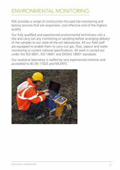
51ADDITIONAL INFORMATION
RSK provides a range of construction-focused site monitoring and testing services that are responsive, cost-effective and of the highest quality.
Our fully qualified and experienced environmental technicians visit a site and carry out any monitoring or sampling before arranging delivery of the samples to our state-of-the-art laboratories. All our field staff are equipped to enable them to carry out gas, flow, vapour and water monitoring to current national specifications. All work is carried out under the ISO 9001, ISO 14001 and OHSAS 18001 standards.
Our analytical laboratory is staffed by very experienced chemists and accredited to BS EN 17025 and MCERTS.
ENVIRONMENTAL MONITORING
52 ADDITIONAL INFORMATION
RSK provides many services complementary to site investigations. Further details can be found at www.rsk.co.uk
RSK SafeGround – PAS128 standard utility surveys: from large-scale mapping projects to clearance of discrete locations before intrusive site investigation works www.safe-ground.co.uk/index.html Ecology – Undertaking habitat and protected species surveys to inform clients of ecological constraints and obtaining development licences to facilitate works as required www.rsk.co.uk/services/esia/ecology.html Geophysics – Applying near-surface geophysical techniques to site investigation, including surface mapping and borehole methods www.rsk.co.uk/geosciences.html Envirolab – A UKAS-accredited laboratory (No. 1247) providing specialist analytical services for a variety of organic and inorganic analyses in a diverse range of matrices www.envlab.co.uk Materials and structures – Provides a comprehensive range of UKAS-accredited on-site and laboratory tests on hardened concrete and other construction materials for quality assurance and structural investigationswww.rsk.co.uk/services/sustainability/building-sciences/construction-materials-evaluation-and-testing.html
Asbestos and legionella – A full range of consultancy services to keep you compliant from surveys and air testing to risk assessments and tank cleaningwww.rsk.co.uk/services/compliance/asbestos-and-water-hygiene
RemedX – cutting-edge, design-led remediation contracting solutions. Experience of all aspects of remediation fieldwork from small projects through to the management of multi-million pound programmeswww.remedx.co.uk
COMPLEMENTARY SERVICES

53ADDITIONAL INFORMATION
TOOL AND EQUIPMENT WEIGHTS
Tool and equipment weights, kg
Cable percussion kit Rotary drilling kit
6-in. casing 1.5 m 59 PW casing 1.5 m 33
8-in. casing 1.5 m 78 PW core barrel 50
10-in. casing 1.0 m 63 PW core barrel 48
10-in. casing 1.5 m 95 SWF core barrel 70
12-in. casing 1.0 m 75 NWY drill rod 1.5 m 15
12-in. casing 1.5 m 113 Box of 1.5 m P core 23
6-in. clay cutter 55 Box of 1.5 m S core 45
8-in. clay cutter 82 Other items
6-in. casing head 13 Breaker and gun 88
8-in. casing head 17 1 m3 (1000 L) of water 1000
6-in. bailer 57 Bag of cement 25
8-in. bailer 86 Bag of sand/ballast 25
U4 hammer/slider 80 Bag of bentonite 25
Top swivel weight 80
Intermediate weight 95
SPT hammer 105
SPT rod 1.0 m 10
Note: Figures quoted are approximate only and may vary with manufacture, etc.
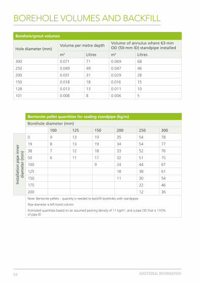
54 ADDITIONAL INFORMATION
BOREHOLE VOLUMES AND BACKFILL
Borehole/grout volumes
Hole diameter (mm)Volume per metre depth Volume of annulus where 63-mm
OD (50-mm ID) standpipe installed
m3 Litres m3 Litres
300 0.071 71 0.069 68
250 0.049 49 0.047 46
200 0.031 31 0.029 28
150 0.018 18 0.016 15
128 0.013 13 0.011 10
101 0.008 8 0.006 5
Bentonite pellet quantities for sealing standpipe (kg/m)
Borehole diameter (mm)
100 125 150 200 250 300
Inst
alla
tion
pip
e in
ner
di
amet
er (m
m)
0 9 13 19 35 54 78
19 8 13 19 34 54 77
38 7 12 18 33 52 76
50 6 11 17 32 51 75
100 9 24 44 67
125 18 38 61
150 11 30 54
175 22 46
200 12 36
Note: Bentonite pellets – quantity is needed to backfill boreholes with standpipes
Pipe diameter is left-hand column
Estimated quantities based on an assumed packing density of 11 kg/m3, and a pipe OD that is 110% of pipe ID

55ADDITIONAL INFORMATION
WHO IS RSK?
RSK is a multidisciplinary environmental and engineering consultancy that has been operating across Europe, the Middle East and Africa for over 25 years. The company offers comprehensive site investigation services through a sound knowledge of all aspects of geotechnical and geoenvironmental engineering. All the required services are in-house, including drilling using a fleet of rigs, service tracing, laboratory testing and remediation contracting.
The company also provides associated services such as ecology, environmental impact assessment, civil and structural engineering, aerial surveys, waste management, and permitting.
RSK has an accredited and integrated safety, health, environmental and quality management system aligned with ISO 9001, ISO 14001 and OHSAS 18001.

Published November 2015
M0348a_1
www.rsk.co.uk
Belfast +44 (0)28 90 660993 Bristol +44 (0)117 947 1000Castleford +44 (0)1977 552255Coventry +44 (0)24 7650 5600Derby +44 (0)1332 542740Dublin +353 (0)1 400 3609Glasgow +44 (0)141 418 0471Helsby +44 (0)1928 726006Hyde (Envirolab) +44 (0)161 368 4921Hemel Hempstead +44 (0)1442 437500Manchester +44 (0)161 236 2757Southampton +44 (0)1794 329276Tonbridge +44 (0)1732 833111
CONTACT US
GROUNDENGINEERINGAWARDS 2015
WINNERGROUND INVESTIGATION
PROJECT OF THE YEAR
0
1
2
3
4
5
6
7
8
9
10
11
12
13
(cm)
Top Related