


Languages
Pages
Legal


KHHCA0204 Kuriyama of America, Inc. 165
™
Engineering Data
How to Determine Correct Assembly Length
Assembly Length
Todeterminethelengthofhoseneededinmakingassemblieswithpermanentorreusablecouplings,subtractDimension“C”(Cutofffactor)foreachcouplingfromtherequiredoverallassemblylength.Dimension“C”maybefoundinthecouplingspecificationtables.
Rememberthathydraulichoseunderpressurewillelongateupto2%ofitslengthorcontractupto4%dependingonpressure,typeandsize.Sufficientallowanceshouldbemadetopermitsuchchangesinlength.
Formostassemblies,thecorrectassemblylengthmaybedeterminedbydirectmeasurementoftheequipmentoradrawing.Minimumbendradiiasshowninthehosespecificationtablesshouldbeobserved.
Assembliesaremeasuredtotheendoftheseal.
159_199(NEW06).indd165 6/19/064:15:13PM

166 Kuriyama of America, Inc. KHHCA0204
™
Engineering Data
Occasionallyanassemblywillberequiredsimilartothesketchestotheright.Thefollowingequationsarehelpfulindeterminingthecorrectlength:
FOR180°TURNAPPLICATIONS
#1L=2A+πR
#2L=2A+πR+T
L=Overalllengthofthehydraulichoseassembly,inmmorinches.
A=Allowanceforaminimumstraightsectionofhydraulichoseateachendoftheassembly,measurefromtheouterendofeachcoupling,inmmorinches.Thesetwostraightsectionsarenecessarytopreventexcessivestressconcentrationsdirectlybackofthecouplings.Seetablebelow.
R=Bendingradiusofthehose,inmmorinches.Seehosespecificationstables.
T=Amountoftravel,inmmorinches.
Oftenrightangleadaptersprovideaconvenientmeansofavoidingabendradiusthatistoosmall.
Angle CouplingsA–Tomeasureangleofoffsetofahoseassembly,pointoneendofcoupling“A”(thenearest)toaverticalpositiondownward.Theanglecanthenbemeasuredfromthecenterlineofthisverticalcoupling“B”(thefarcoupling).Seeillustrationatright.
Relationshipscanthenbeexpressedfrom0°to360°.Ifangleisnotgiven,elbowsarepositionedat0°.
Length Tolerance for Hydraulic Hose Assemblies and Specified Hose LengthsLength ToleranceForlengthsfrom0uptoandincluding12”(305mm) ±1/8”±3mmForlengths>12”(305mm)<18”(457mm) ±3/16”±5mmForlengths>18”(457mm)<36”(914mm) ±1/4”±6mmForlengths>36”(914mm)<48”(1219mm) ±3/8”±10mmForlengths>48”(1219mm)<72”(1830mm) ±1/2”±13mmForlengths>72”(1830mm) ±1%
ElbowangleandangleofOrientation Tolerance±3
Hose in. 1/4 5/16 3/8 1/2 5/8 3/4 1 11/4 11/2 2 ID mm 6.4 7.9 9.5 12.7 15.9 19 25 31.8 38.1 50.8 Min. in. 5 5 5 6 6 7 8 9 10 11 “A” mm 127 127 127 152 152 178 203 229 254 279
Assembly Length
159_199(NEW06).indd166 6/19/064:15:16PM

KHHCA0204 Kuriyama of America, Inc. 167
™
Engineering Data
Fitting Identification
Comparethemeasurementstakentothecouplingsshowninthecouplingspecificationtablesthatappearinthiscatalog.
Measuring Threads and Seat Angles
Useathreadpitchgauge(seeillustrationbelow)todeterminethenumberofthreadsperinchorthedistancebetweenthreadsinmetricconnections.Placethegaugeonthethreads(seeillustrationsatright)untilthefitissnug.Matchthemeasurementtothechart.
Measuring ThreadsWiththecalliper,measurethethreaddiameteratthelargestpoint.(O.D.ofmalethreads–I.D.offemalethreads).Seeillustrationatright.
Measuring Seat AnglesWhenthecenterlineoftheseatgaugeextendsparalleltotheprojectedlongitudinalaxisofthecoupling,thentheanglesofthegaugeandseatmatch.Seeillustrationatright.
159_199(NEW06).indd167 6/19/064:15:18PM

168 Kuriyama of America, Inc. KHHCA0204
™
Engineering Data
Fitting IdentificationFitting Identification
NPSM – (National Pipe Straight Mechanical)
Nationalpipestraightthreadformechanicaljoint.Thisisusedonthefemaleswivelnutofironpipeswiveladapters.Theleak-resistantjointisnotmadebythesealingfitofthreads,butbyataperedseatinthecouplingend.Thisconnectionissometimesusedinfluidpowersystems.
NPSF – (National Pipe Straight Thread for Fuels)
TheNationalpipestraightthreadforfuels.ThisissometimesusedforfemaleendsandproperlymateswiththeNPTFmaleend.However,theSAErecommendstheNPTFthreadinpreferencetotheNPSFforfemaleends.
Dash NumbersMostfluidpipingsystemsizesaremeasuredbydashnumbers.Theseareuniversallyusedabbreviationsforthesizeofacomponentexpressedasthenumeratorofthefractionwiththedenominatoralwaysbeing16.Forexample,a-04portis4/16or1/4inch.Dashnumbersareusuallynominal(innameonly)andareabbreviationsthatmaketheorderingofcomponentseasier.
Thereareafewcouplingsystemsusedforhydraulicconnections.Theyareidentifiedas:
American, British, French, German, Japanese
Thissectionliststheoriginandcouplingstyle.Descriptionsanddimensionaldatafolloweachcouplingstyle.
American Thread TypesNPTF – (National Pipe Tapered Fuel)
Thisisadrysealthread,theNationalpipetaperedthreadforfuels.Thisisusedforbothmaleandfemaleends.Thisconnectionisstillwidelyusedinfluidpowersystems,eventhoughitisnotrecommendedbytheNationalFluidPowerAssociations(N.F.P.A.)foruseinhydraulicapplications.
TheNPTFmalewillmatewiththeNPTF,NPSF,orNPSMfemale.
TheNPTFmalehastaperedthreadsanda30°invertedseat.TheNPTFfemalehastaperedthreadsandnoseat.Thesealtakesplacebydeformationofthethreads.TheNPSMfemalehasstraightthreadsanda30°invertedseat.Thesealtakesplaceonthe30°seat.
TheNPTFconnectorissimilarto,butnotinterchangeablewith,theBSPTconnector.Thethreadpitchisdifferentinmostsizes.Also,thethreadangleis60°insteadofthe55°anglefoundonBSPTthreads.
Dash Inch Thread FemaleThread MaleThread Size Size Size ID OD (in) (in-TPI) (mm) (in) (mm) (in) -02 1/8 1/8-27 8.7 0.34 10.3 0.41 -04 1/4 1/4-18 11.9 0.47 14.3 0.56 -06 3/8 3/8-18 15.1 0.59 17.5 0.69 -08 1/2 1/2-14 18.3 0.72 21.4 0.84 -12 3/4 3/4-14 23.8 0.94 27.0 1.06 -16 1 1-111/2 30.2 1.19 33.3 1.31 -20 11/4 11/4-111/2 38.9 1.53 42.9 1.69 -24 11/2 11/2-111/2 44.5 1.75 48.4 1.91 -32 2 2-111/2 57.2 2.25 60.3 2.38
Thread Identification TableNational Pipe Straight Mechanical (NPSM)National Pipe Tapered for Fuels (NPTF)
159_199(NEW06).indd168 6/19/064:15:18PM

KHHCA0204 Kuriyama of America, Inc. 169
™
Engineering Data
AmericanSAE J514 Straight Thread O-Ring Boss (ORB)
SAE J514 37° (JIC)
ThemalehasstraightthreadsandanO-ring.Thefemalehasstraightthreadsandasealingface.ThesealismadeattheO-ringonthemaleandsealingfaceonthefemale.
Thethreadsholdtheconnectionmechanically.
Dash Inch Thread FemaleThread MaleThread Size Size Size ID OD (in) (in-TPI) (mm) (in) (mm) (in) -02 1/8 5/16-24 6.9 0.27 7.8 0.31 -03 3/16 3/8-24 8.5 0.34 9.4 0.37 -04 1/4 7/16-20 9.9 0.39 11.2 0.44 -05 5/16 1/2-20 11.5 0.45 12.6 0.49 -06 3/8 9/16-18 12.9 0.51 14.1 0.56 -08 1/2 3/4-16 17.5 0.69 18.9 0.74 -10 5/8 7/8-14 20.5 0.81 22.1 0.87 -12 3/4 11/16-12 24.9 0.98 26.9 1.06 -14 7/8 13/16-12 28.1 1.11 30.0 1.18 -16 1 15/16-12 31.3 1.23 33.1 1.31 -20 11/4 15/8-12 39.2 1.54 41.1 1.62 -24 11/2 17/8-12 45.6 1.79 47.4 1.87 -32 2 21/2-12 61.4 2.42 63.3 2.49
Thread Identification TableSAE J514 Straight Thread O-Ring Boss
TheSocietyofAutomotiveEngineers(SAE)specifiesa37°angleflareorseatbeusedwithhighpressurehydraulictubing.ThesearecommonlycalledJICcouplings.
TheJIC37°flaremalewillonlymatewithaJICfemale.
TheJICmalehasstraightthreadsanda37°flareseat.
ThisportconnectionisrecommendedbytheN.F.P.A.foroptionalleakagecontrolinmediumandhighpressurehydraulicsystems.TheO-ringbossmalewillmatewithanO-ringbossfemaleonly.
Thefemaleisgenerallyfoundonports.
TheJICfemalehasstraightthreadsanda37°flareseat.
Thesealismadeonthe37°flareseatbyestablishingalinecontactbetweenthemaleflareandthefemaleconeseat.Thethreadsholdtheconnectionmechanically.
CAUTION:Inthe-02,-03,-04,-05,-08and-10sizes,thethreadsoftheSAE45°flareandtheSAE37°flarearethesame.However,thesealingsurfaceanglesarenotthesame.Carefullymeasuretheseatangletodifferentiate.
Dash Inch Thread FemaleThread MaleThread Size Size Size ID OD (in) (in-TPI) (mm) (in) (mm) (in) -02 1/8 5/16-24 6.9 0.27 7.8 0.31 -03 3/16 3/8-24 8.5 0.34 9.4 0.37 -04 1/4 7/16-20 9.9 0.39 11.2 0.44 -05 5/16 1/2-20 11.5 0.45 12.6 0.49 -06 3/8 9/16-18 12.9 0.51 14.1 0.56 -08 1/2 3/4-16 17.5 0.69 18.9 0.74 -10 5/8 7/8-14 20.5 0.81 22.1 0.87 -12 3/4 11/16-12 24.9 0.98 26.9 1.06 -14 7/8 13/16-12 28.1 1.11 30.0 1.18 -16 1 15/16-12 31.3 1.23 33.1 1.31 -20 11/4 15/8-12 39.2 1.54 41.1 1.62 -24 11/2 17/8-12 45.6 1.79 47.4 1.87 -32 2 21/2-12 61.4 2.42 63.3 2.49
Thread Identification TableSAE J514 37° Flare (JIC)
SAE Straight Thread O-Ring Boss
37° Flare (JIC)
159_199(NEW06).indd169 6/19/064:15:20PM

170 Kuriyama of America, Inc. KHHCA0204
™
American (Continued)
Dash Inch Thread FemaleThread MaleThread Size Size Size ID OD (in) (in-TPI) (mm) (in) (mm) (in) -02 1/8 5/16-24 6.9 0.27 7.9 0.31 -03 3/16 3/8-24 8.6 0.34 9.6 0.38 -04 1/4 7/16-20 9.9 0.39 11.2 0.44 -05 5/16 1/2-20 11.4 0.45 12.7 0.50 -06 3/8 5/8-18 14.2 0.56 15.7 0.62 -07 7/16 11/16-16 15.7 0.62 17.3 0.68 -08 1/2 3/4-16 17.0 0.68 19.0 0.75 -10 5/8 7/8-14 20.3 0.80 22.3 0.88 -12 3/4 11/16-14 25.1 0.99 26.9 1.06 -14 7/8 11/4-12 29.5 1.16 31.7 1.25 -16 1 13/8-12 32.5 1.28 35.0 1.38
Thread Identification TableSAE J512 45°
Dash Inch Thread FemaleThread MaleThread Size Size Size ID OD (in) (in-TPI) (mm) (in) (mm) (in) -04 1/4 9/16-18 12.9 0.51 14.1 0.56 -06 3/8 11/16-16 15.9 0.63 17.3 0.68 -08 1/2 13/16-16 19.1 0.75 20.5 0.81 -10 5/8 1-14 23.6 0.93 23.2 0.99 -12 3/4 13/16-12 28.1 1.11 30.0 1.18 -16 1 17/16-12 34.4 1.36 36.3 1.43 -20 11/4 111/16-12 40.8 1.61 42.7 1.68 -24 11/2 2-12 48.7 1.92 50.6 1.99
Thread Identification TableSAE J1453 O-Ring Face Seal (ORFS)
AsealismadewhentheO-ringinthemalecontactstheflatfaceonthefemale.Couplingsareintendedforhydraulicsystemswhereelastomericsealsareacceptabletoovercomeleakageandleakresistanceiscrucial.Thisconnectionofferstheverybestleakagecontrolavailabletoday.
SAE J1453 O-Ring Face Seal (ORFS)Themaleconnectorhasastraightthreadandamachinedflatface.Thefemalehasastraightthreadandamachinedflatface.ThesealtakesplacebycompressingtheO-ringontotheflatfaceofthefemale,similartothesplitflangetypefitting.Thethreadsholdtheconnectionmechanically.
SAE J512 45°Atermusuallyappliedtofittingshavinga45°angleflareorseat.Softcoppertubingisgenerallyusedinsuchapplicationsasitiseasilyflaredtothe45°angle.Theseareforlowpressureapplications–commonlyusedinrefrigeration,automotiveandtruckpipingsystems.TheSAE45°flaremalewillmatewithanSAE45°flarefemaleonly
TheSAEmalehasstraightthreadsanda45°flareseat.
TheSAEfemalehasstraightthreadsanda45°flareseat.
Thesealismadeonthe45°flareseat.
Thethreadsholdtheconnectionmechanically.
CAUTION:Inthe-02,-03,-04,-05,-08and-10sizes,thethreadsoftheSAE45°flareandtheSAE37°flarearethesame.However,thesealingsurfaceanglesarenotthesame.Carefullymeasuretheseatangletodifferentiate.
O-Ring Face Seal (ORFS)
SAE 45° Flare
Engineering Data
159_199(NEW06).indd170 6/19/064:15:21PM

KHHCA0204 Kuriyama of America, Inc. 171
™
American (Continued)
Dash Inch Thread FemaleThread MaleThread Size Size Size ID OD (in) (in-TPI) (mm) (in) (mm) (in) -02 1/8 5/16-28 6.9 0.27 7.9 0.31 -03 3/16 3/8-24 8.6 0.34 9.6 0.38 -04 1/4 7/16-24 9.9 0.39 11.2 0.44 -05 5/16 1/2-20 11.4 0.45 12.7 0.50 -06 3/8 5/8-18 14.2 0.56 15.7 0.62 -07 7/16 11/16-18 15.7 0.62 17.3 0.68 -08 1/2 3/4-18 17.0 0.68 19.0 0.76 -10 5/8 7/8-18 20.3 0.80 22.3 0.88 -12 3/4 11/16-16 25.1 0.99 26.9 1.06
Thread Identification TableSAE J512 Inverted Flare
ThisisaradialO-ringsealconnectioncommonlyusedforhydraulicapplicationsinundergroundmines.ThemalecontainsanexteriorO-ringandbackupring,plus,agroovetoacceptthe“staple.”Thefemalehasasmoothborewithtwoholesforthestaple.
SAE J1467 Clip Fastener (Press-Lok Connector)A“U”shapedstapleorretainingclipisinsertedthroughthetwoholes,passingthroughthegrooveinthemaletolocktheconnectiontogether.ThesealtakesplacebycontactbetweentheO-ringinthemaleandthesmoothboreofthefemale.
SAE J512 Inverted FlareThisconnectionisfrequentlyusedinautomotivesystems.Themaleconnectorcaneitherbea45°flareinthetubefittingformora42°seatinthemachinedadapterform.
Thefemalehasastraightthreadwitha42°invertedflare.Thesealtakesplaceontheflaredsurface.Thethreadsholdtheconnectionmechanically.
Dash Inch Male Female Size Size OD ID (in) (mm) (in) (mm) -04 1/4 19/32 14.9 19/32 15.1 -06 3/8 25/32 19.9 51/64 20.1 -08 1/2 15/16 23.9 61/64 24.1 -12 3/4 19/64 28.9 19/64 29.1 -16 1 117/32 38.9 135/64 39.1 -20 11/4 113/16 45.9 113/16 46.1 -24 11/2 25/32 54.9 211/64 55.2 -32 2 233/64 63.9 217/32 64.2
Connector Identification TableSAE J1467 Clip Fastener
Press-Lok Connectors
Male Press-Lok Connector
Female Press-Lok Connector
Engineering Data
159_199(NEW06).indd171 6/19/064:15:22PM

172 Kuriyama of America, Inc. KHHCA0204
™
American (Continued)
SAE J518/DIN20066/ISO-DIS 6162/JIS B8363 O-ring Flanges
How to MeasureFourBoltFlange–Firstmeasuretheportholediameterusingthecalliper.Next,measurethelongestboltholespacingfromcentre-to-centre(Dimension“A”)ormeasuretheflangedheaddiameter.OD
Therearethreeexceptions:
1. Thesize-10,whichiscommonoutsideofNorthAmericaisnotanSAEStandardsize.
2. Caterpillarflanges,whicharethesameflangeODasSAECode62,haveathickerflangehead.
3. Poclainflanges,whicharecompletelydifferentfromSAEflanges.
Note:AllCode61flangeheadhosecouplingsmeetorexceedSAEJ518Code61requirementsforhydraulicsplitflangeconnections.TheCode61flangeheaddesigncanwithstandamaximumoperatingpressureof3000to5000psi,dependingonsize.
Thisconnectioniscommonlyusedinfluidpowersystems.Therearetwopressureratings.Code61FormR,PN35/350bar,TypeI,isreferredtoasthe“standard”seriesandCode62FormS,PN415bar,TypeII,isthe“heavyduty”“6000psi”series.Thedesignconceptforbothseriesisthesame,buttheboltholespacingandflangedheaddiametersarelargerforthehigherpressure,Code62connection.
Thefemale(port)isanunthreadedholewithfourboltholesinarectangularpatternaroundtheport.
Themaleconsistsofaflangedhead,groovedforanO-ring,andeitheracaptiveflangeorsplitflangehalveswithboltholestomatchtheport.ThesealtakeplaceontheO-ring,whichiscompressedbetweentheflangeheadandtheflatsurfacesurroundingtheport.Thethreadedboltsholdtheconnectiontogether.
SAEJ518,DIN20066,ISO/DIS6162andJISB8363areinterchangeable,exceptforboltsizes.
SAE Code 61 and Code 62 4-Bolt Split Flange
* -10isanon-SAEsizeflange.
Flange Flange Flange Flange Flange Flange Flange Dash Size Thickness Size Thickness Size Thickness Size (in) (mm) (in) (mm) (in) (mm) (in) (mm) (in) (mm) (in) (mm) -08 1.19 30.2 .265 6.7 1.25 31.8 .305 7.7 -10* 1.34 34.0 .265 6.7 -12 1.50 38.1 .265 6.7 1.63 41.3 .345 8.7 1.63 41.3 .56 14.2 -16 1.75 44.5 .315 8.0 1.88 47.6 .375 9.5 1.88 47.6 .56 14.2 -20 2.00 50.8 .315 8.0 2.13 54.0 .405 10.3 2.13 54.0 .56 14.2 -24 2.38 60.3 .315 8.0 2.50 63.5 .495 12.6 2.50 63.5 .56 14.2 -32 2.81 71.4 .375 9.5 3.13 79.4 .495 12.6 3.13 79.4 .56 14.2 -40 3.31 84.1 .375 9.5
Flange Head Guide
Engineering Data
159_199(NEW06).indd172 6/19/064:15:23PM

KHHCA0204 Kuriyama of America, Inc. 173
™
Engineering Data
British Connections
British Standard Pipe Tapered
TheBSPT(tapered)malewillmatewithaBSPT(tapered)female,oraBSPP(parallel)female.
TheBSPTmalehastaperedthreads.WhenmatingwitheithertheBSPT(tapered)femaleortheBSPP(parallel)femaleport,thesealismadeonthethreadsaccomplishedbythreaddistortion.Athreadsealantisrecommended.
TheBSPTconnectorissimilarto,butnotinterchangeablewith,theNPTFconnector.Thethreadpitchisdifferentinmostcases,andthethreadangleis55°insteadofthe60°anglefoundonNPTFthreads.
British Standard Pipe Parallel
PopularcouplingsBritishStandardPipe(BSP)threads,alsoknownasWhitworththreads.
TheBSPP(parallel)malewillmatewithaBSPP(parallel)femaleorafemaleport.
TheBSPPmalehasstraightthreadsanda30°seat.
TheBSPPfemalehasstraightthreadsanda30°seat.
Thefemaleporthasstraightthreadsandaspotface.ThesealontheportismadewithanO-Ringorsoftmetalwasheronthemale.
TheBSPP(parallel)connectorissimilarto,butnotinterchangeablewith,theNPSMconnector.Thethreadpitchisdifferentinmostsizes,andthethreadangleis55°insteadofthe60°anglefoundonNPSMthreads.ThefemaleswivelisBSPPhasataperednosewhichsealsontheconeseatofthemale.
Dash Inch Thread FemaleThread MaleThread Size Size Size ID OD (in) (in-TPI) (mm) (in) (mm) (in) -02 1/8 1/8-28 8.71 0.34 9.5 0.38 -04 1/4 1/4-19 11.1 0.44 13.5 0.53 -06 3/8 3/8-19 15.1 0.59 16.7 0.66 -08 1/2 1/2-14 18/3 0.72 20.6 0.81 -10 5/8 5/8-14 20.6 0.81 23.0 0.91 -12 3/4 3/4-14 23.8 0.94 26.2 1.03 -16 1 1-11 30.2 1.19 33.3 1.31 -20 11/4 11/4-11 38.9 1.53 42.1 1.66 -24 11/2 11/2-11 45.2 1.78 47.6 1.88 -32 2 2-11 56.4 2.22 59.5 2.34
Thread Identification TableBritish Standard Pipe Parallel & Tapered (BSPP & PSPT)
159_199(NEW06).indd173 6/19/064:15:24PM

174 Kuriyama of America, Inc. KHHCA0204
™
Engineering Data
French Connections
FrenchGAZhavea24°seatandmetricthreads.ThesearesimilartoGermanDINcouplings,butthethreadsaredifferentinsomesizes,theFrenchusefinethreadsinallsizes.FrenchflangesaredifferentthanSAE,theyhavealipthatprotrudesfromtheflangeface.ThesearePoclainstyleflanges.
Millimetrique and GAZ 24°
Thisconnectionconsistsofacommonmaleandtwodifferentfemales.
TheFrenchMetric(GAZ)malewillmatewiththefemale24°coneorthefemaletubefitting.
Themalehasa24°seatandstraightmetricthreads.Thefemalehasa24°seatoratubingsleeveandstraightmetricthreads.TheMillimetriqueSeriesisusedwithwholenumbermetricO.D.tubingandtheGAZSeriesisusedwithfractionalnumbermetricO.D.pipesizetubing.
GAZ Poclain 24° Flange
ThePoclain(FrenchGAZ)24°highpressureflangeisusuallyfoundonPoclainequipment.
Themaleflangewillmatewithafemaleflangeorport.
Thesealismadeonthe24°seat.
Metric FemaleThread MaleThread Tube Thread ID OD OD(Dia.XPitch) (mm) (in.) (mm) (in) (mm) (in) M12X1.0 11.0 0.43 12.0 0.47 6 0.24 M14X1.5 12.5 0.49 14.0 0.55 8 0.31 M16X1.5 14.5 0.57 16.0 0.63 10 0.39 M18X1.5 16.5 0.65 18.0 0.71 12 0.47 M20X1.5 18.5 0.73 20.0 0.79 14 0.55 M22X1.5 20.5 0.81 22.0 0.87 15 0.59 M24X1.5 22.5 0.89 24.0 0.94 16 0.63 M27X1.5 25.5 1.00 27.0 1.06 18 0.71 M30X1.5 28.5 1.12 30.0 1.18 22 0.87 M33X1.5 31.5 1.24 33.0 1.30 25 0.98 M36X1.5 34.5 1.36 36.0 1.42 28 1.10 M39X1.5 37.5 1.48 39.0 1.54 30 1.18 M42X1.5 40.5 1.59 42.0 1.65 32 1.26 M45X1.5 43.5 1.71 45.0 1.77 35 1.38 M48X1.5 46.5 1.83 48.0 1.89 38 1.50 M52X1.5 50.5 1.99 52.0 2.05 40 1.57 M54X2.0 51.9 2.04 54.0 2.13 45 1.77
Thread Identification TableFrench Metric Millimetrique
Dash Inch FemaleThread MaleThread TubeOD Size Size ID OD 60°Cone(Dash)(Dia.XPitch) (mm) (in) (mm) (in) (mm) (in) -6 M20X1.5 18.5 0.73 20.0 0.78 13.25 0.52 -8 M24X1.5 22.5 0.89 24.0 0.94 16.75 0.66 -10 M30X1.5 28.5 1.12 30.0 1.18 21.25 0.83 -12 M36X1.5 34.5 1.36 36.0 1.41 26.75 1.05 -16 M45X1.5 43.5 1.71 45.0 1.77 33.50 1.32 -20 M52X1.5 50.5 1.99 52.0 2.04 42.25 1.66
Thread Identification TableFrench Metric GAZ 24° Cone
159_199(NEW06).indd174 6/19/064:15:25PM
KHHCA0204 Kuriyama of America, Inc. 175
™
Engineering Data
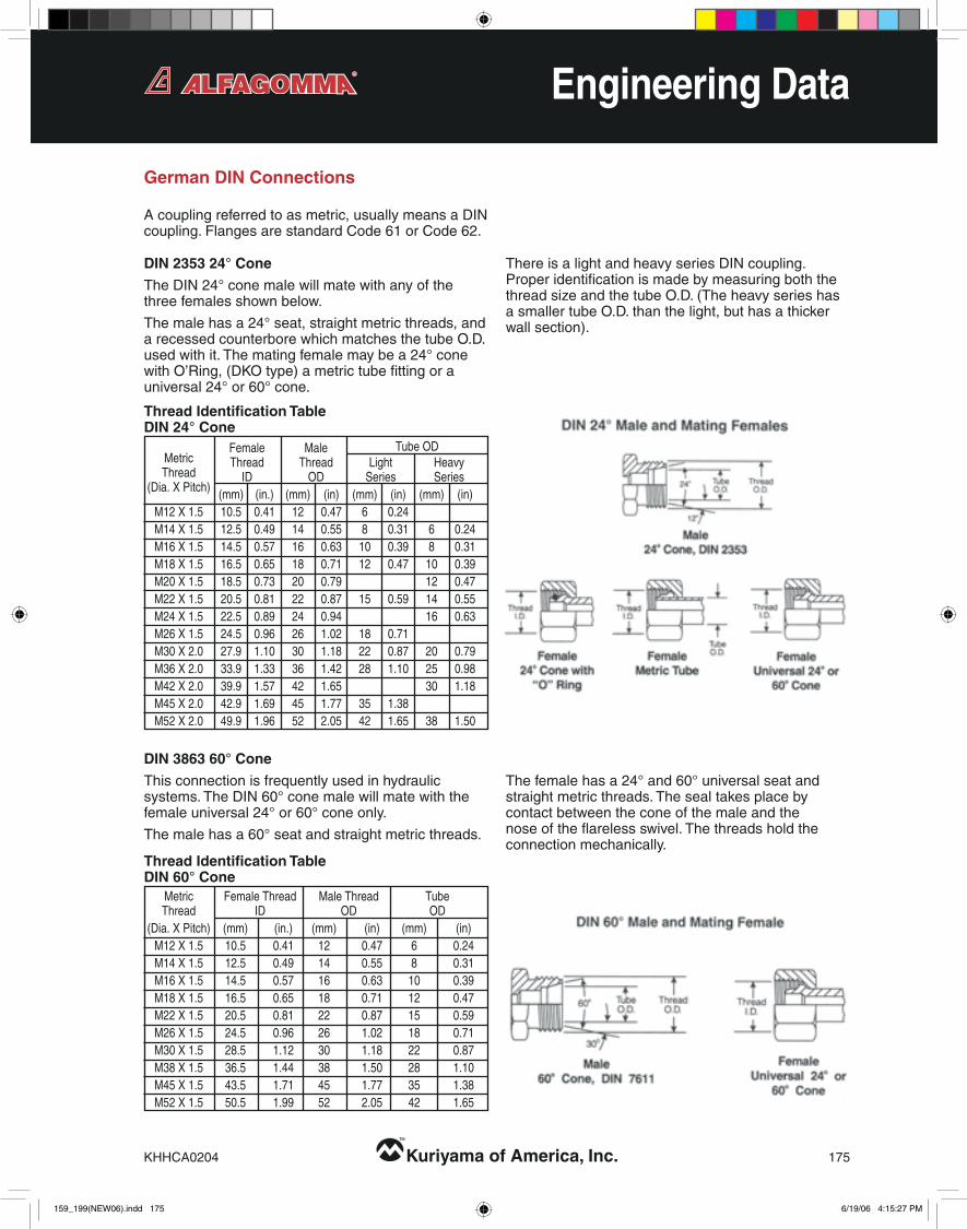
German DIN Connections
Acouplingreferredtoasmetric,usuallymeansaDINcoupling.FlangesarestandardCode61orCode62.
DIN 2353 24° Cone
TheDIN24°conemalewillmatewithanyofthethreefemalesshownbelow.
Themalehasa24°seat,straightmetricthreads,andarecessedcounterborewhichmatchesthetubeO.D.usedwithit.Thematingfemalemaybea24°conewithO’Ring,(DKOtype)ametrictubefittingorauniversal24°or60°cone.
ThereisalightandheavyseriesDINcoupling.ProperidentificationismadebymeasuringboththethreadsizeandthetubeO.D.(TheheavyserieshasasmallertubeO.D.thanthelight,buthasathickerwallsection).
Thisconnectionisfrequentlyusedinhydraulicsystems.TheDIN60°conemalewillmatewiththefemaleuniversal24°or60°coneonly.
Themalehasa60°seatandstraightmetricthreads.
Thefemalehasa24°and60°universalseatandstraightmetricthreads.Thesealtakesplacebycontactbetweentheconeofthemaleandthenoseoftheflarelessswivel.Thethreadsholdtheconnectionmechanically.
DIN 3863 60° Cone
Female Male TubeOD Metric Thread Thread Light Heavy Thread ID OD Series Series(Dia.XPitch) (mm) (in.) (mm) (in) (mm) (in) (mm) (in) M12X1.5 10.5 0.41 12 0.47 6 0.24 M14X1.5 12.5 0.49 14 0.55 8 0.31 6 0.24 M16X1.5 14.5 0.57 16 0.63 10 0.39 8 0.31 M18X1.5 16.5 0.65 18 0.71 12 0.47 10 0.39 M20X1.5 18.5 0.73 20 0.79 12 0.47 M22X1.5 20.5 0.81 22 0.87 15 0.59 14 0.55 M24X1.5 22.5 0.89 24 0.94 16 0.63 M26X1.5 24.5 0.96 26 1.02 18 0.71 M30X2.0 27.9 1.10 30 1.18 22 0.87 20 0.79 M36X2.0 33.9 1.33 36 1.42 28 1.10 25 0.98 M42X2.0 39.9 1.57 42 1.65 30 1.18 M45X2.0 42.9 1.69 45 1.77 35 1.38 M52X2.0 49.9 1.96 52 2.05 42 1.65 38 1.50
Thread Identification TableDIN 24° Cone
Metric FemaleThread MaleThread Tube Thread ID OD OD(Dia.XPitch) (mm) (in.) (mm) (in) (mm) (in) M12X1.5 10.5 0.41 12 0.47 6 0.24 M14X1.5 12.5 0.49 14 0.55 8 0.31 M16X1.5 14.5 0.57 16 0.63 10 0.39 M18X1.5 16.5 0.65 18 0.71 12 0.47 M22X1.5 20.5 0.81 22 0.87 15 0.59 M26X1.5 24.5 0.96 26 1.02 18 0.71 M30X1.5 28.5 1.12 30 1.18 22 0.87 M38X1.5 36.5 1.44 38 1.50 28 1.10 M45X1.5 43.5 1.71 45 1.77 35 1.38 M52X1.5 50.5 1.99 52 2.05 42 1.65
Thread Identification TableDIN 60° Cone
159_199(NEW06).indd175 6/19/064:15:27PM

176 Kuriyama of America, Inc. KHHCA0204
™
Engineering Data
German DIN Connections (Continued)
Metric Standpipe
Ametricstandpipeiscomprisedofthreecomponentsattachedtoamalefitting.Thecomponentsare:aStandpipe,BiteSleeveandMetricNut.ThenutisplacedovertheStandpipe,followedbytheBiteSleeve(seeillustrationbelow).ForDINlightassemblies,aDINlightmetricnutisused.ForDINheavyassemblies,aDINheavymetricnutisused.TheBiteSleeveandStandpipeareselectedonthebasisoftubeO.D.
TubeO.D. MetricNutThread (mm) Light Heavy 6 M12x1.5 8 M14x1.5 M16x1.5 10 M16x1.5 M18x1.5 12 M18x1.5 M20x1.5 15 M22x1.5 16 M24x1.5 18 M26x1.5 20 M30x2.0 22 M30x2.0 25 M36x2.0 28 M36x2.0 30 M42x2.0 35 M45x2.0 38 M52x2.0 42 M52x2.0
159_199(NEW06).indd176 6/19/064:15:28PM

KHHCA0204 Kuriyama of America, Inc. 177
™
Engineering Data
Japanese Connections
JIS Tapered Pipe Thread (PT)
JIS B 0203
TheJIStaperedpipethreadconnectionissimilartotheBSPTconnectionandfullyinterchangeable.TheJapaneseconnectiondoesnothavea30°Flare,andwillnotmatewiththeBSPPfemale.ThethreadsconformtoJISB0203,sameasBSPTthreads.
ThesealontheJIStaperedpipethreadconnectionismadeonthethreads.
JIS 30° Inverted Seat, Parallel Pipe Threads
JIS B 0202
TheJISparallelissimilartotheBSPPconnection.TheJISparallelthreadandtheBSPPconnectionareinterchangeable.
JIS 30° Flare Parallel Pipe Threads
JIS B 0202
TheseJapanese30°flaremalecouplingwillmatewithaJapanese30°flarefemaleonly.
Themaleandfemalehavestraightthreadsanda30°seat.Thesealismadeonthe30°seat.
ThethreadsontheJapanese30°flareconnectorconformtoJISB020,thesameastheBSPPthreads.BoththeBritishandJapaneseconnectorshavea30°seat,buttheyarenotinterchangeable,becausetheBritishseatisinverted.
JapaneseequipmentusesJIS(JapaneseIndustrialStandard)couplingswitha30°seatandBritishStandardPipeParallelthreads.Allflangesarecode61orCode62(except-10).
Thread Identification TableJIS Tapered Pipe, 30° Flare Parallel Pipe, and 30° Male Inverted Seat
Dash Inch Thread FemaleThread MaleThread Size Size Size ID OD (in) (in-TPI) (mm) (in) (mm) (in) -02 1/8 1/8-28 8.7 0.34 9.5 0.38 -04 1/4 1/4-19 11.9 0.47 13.5 0.53 -06 3/8 3/8-19 15.1 0.59 16.7 0.66 -08 1/2 1/2-14 19.1 0.75 20.6 0.81 -10 5/8 5/8-14 20.6 0.81 23.1 0.91 -12 3/4 3/4-14 23.8 0.94 26.2 1.03 -16 1 1-11 30.2 1.19 33.3 1.31 -20 11/4 11/4-11 38.9 1.53 42.1 1.66 -24 11/2 11/2-11 45.2 1.78 47.6 1.88 -32 2 2-11 56.4 2.22 59.5 2.34
159_199(NEW06).indd177 6/19/064:15:29PM

178 Kuriyama of America, Inc. KHHCA0204
™
Engineering Data
Komatsu Style 30° Flare Parallel Threads
TheKomatsustyle30°FlareParallelthreadcouplingisidenticaltotheJapanese30°Flareparallelexceptforthethreads.TheKomatsuusesMetricfinethreadswhichconformtoJISB0207.
TheKomatsuconnectorsealsonthe30°Flare.
Komatsu Flange Fitting
TheKomatsuFlangefittingisnearlyidenticaltoandfullyinterchangeablewiththeSAECode61flangefitting.InallsizestheO-ringdimensionsaredifferent.WhenreplacingaKomatsuflangewithanSAEstyleflange,anSAEstyleO-ringmustbeused.
Japanese Connections (Continued)
Male B Flange NominalSize Metric Thread Thread Dash Thread O.D. I.D. Size (in) (mm) Size (mm) (mm) -06 3/8 9.5 M18x1.5 18 16.4 -08 1/2 13 M22x1.5 22 20.4 -10 5/8 16 M24x1.5 24 22.4 -12 3/4 19 M30x1.5 30 28.4 -16 1 25 M33x1.5 33 31.4 -20 11/4 32 M36x1.5 36 34.4 -24 11/2 38 M42x1.5 42 40.4
*Thisisanon-SAEsizeflange
Flange Flange Dash
NominalSize Size A B
Size (In.) (mm) (In.) (In.) (In.) -08 1/2 12.7 1.19 .73 .98 -10* 5/8 15.9 1.34 .73 1.10 -12 3/4 19.1 1.50 .85 1.22 -16 1 25.4 1.75 1.12 1.50 -20 11/4 31.8 2.00 1.36 1.73 -24 11/2 38.1 2.38 1.75 2.12 -32 2 50.8 2.81 2.22 2.56
159_199(NEW06).indd178 6/19/064:15:31PM

KHHCA0204 Kuriyama of America, Inc. 179
™
Engineering Data
Recommended Fitting and Adapter Installation Torque
Dash Thread lb.ft. N.m Size Size Min Max Min Max -04 7/16-20 11 12 15 16 -05 1/2-20 14 15 19 21 -06 9/16-18 18 20 24 28 -08 3/4-16 36 39 49 53 -10 7/8-14 57 63 77 85 -12 11/16-12 79 88 107 119 -14 13/16-12 94 103 127 140 -16 15/16-12 108 113 147 154 -20 15/8-12 127 133 172 181 -24 17/8-12 158 167 215 226 -32 21/2-12 245 258 332 350
SAE J514 37° Flare (JIC)
Dash Thread lb.ft. N.m Size Size Min Max Min Max -08 1/2 15 19 20 25 -12 3/4 21 29 28 40 -16 1 27 35 37 48 -20 11/4 35 46 48 62 -24 11/2 46 58 62 79 -32 2 54 66 73 90 -40 21/2 79 91 107 124 -48 3 137 149 186 203
SAE J518 Code 61 Flange Half Bolt
Dash Thread lb.ft. N.m Size Size Min Max Min Max -08 1/2 15 19 20 25 -12 3/4 25 33 34 45 -16 1 42 50 56 68 -20 11/4 62 75 85 102 -24 11/2 116 133 158 181 -32 2 199 216 271 294
SAE J518 Code 62 Flange Half Bolt
Dash Thread lb.ft. N.m Size Size Min Max Min Max -04 9/16-18 10 12 14 16 -06 11/16-16 18 20 24 27 -08 13/16-16 32 35 43 47 -10 1-14 46 50 60 68 -12 13/16-12 65 70 90 95 -16 17/16-12 92 100 125 135 -20 111/16-12 125 140 170 190 -24 2-12 150 165 200 225
SAE J1453 O-Ring Face Seal
Dash Thread lb.ft. N.m Size Size -04 1/4-19 19 25 -06 3/8-19 25 34 -08 1/2-14 49 64 -10 5/8-14 100 132 -12 3/4-14 100 132 -16 1-11 149 196 -20 11/4-11 171 225 -24 11/2-11 194 255 -32 2-11 240 316
JIS (B8363)
Thread lb.ft. N.m mm M12x1.5 15 15 M14x1.5 19 25 M16x1.5 33 45 M18x1.5 37 50 M20x1.5 52 70 M22x1.5 55 75 M24x1.5 74 100 M26x1.5 81 110 M30x2 96 160 M36x2 162 220 M42x2 170 230 M45x2 220 300 M52x2 367 500
Metric
BSPP
Dash Thread Torquelb.Ft. TorqueNm Size Size With Without With Without O-Ring O-Ring O-Ring O-Ring -02 1/8-28 N/A 7 N/A 10 -04 1/4-19 15 15 20 20 -06 3/8-19 26 26 35 35 -08 1/2-14 37 44 50 60 -10 5/8-14 44 52 60 70 -12 3/4-14 63 85 85 115 -16 1-11 85 103 115 140 -20 11/4-11 140 155 190 210 -24 11/2-11 177 214 240 290 -32 2-11 221 295 300 400
Please note that the recommended values shown on this page change on a periodic basis. These are the known recommended values as set by the appropriate agency standards at the time of this catalog printing.
159_199(NEW06).indd179 6/19/064:15:31PM

180 Kuriyama of America, Inc. KHHCA0204
™
Inches mm 1/64 .0156 .397 1/32 .0312 .794 3/64 .0468 1.191 1/16 .0625 1.588 5/64 .0781 2.381 3/32 .0937 2.381 7/64 .1093 2.778 1/8 .1250 3.175 9/64 .1406 3.572 5/32 .1562 3.969 11/64 .1718 4.366 3/16 .1875 4.763 13/64 .2031 5.159 7/32 .2187 5.556 15/64 .2343 5.963 1/4 .2500 6.350
Engineering Data
Kilo Mega Bar Poundsper Pascals Pascals (Bar) SquareInch (kPa) (MPa) (PSI) 100 0.1 1 14.5 200 0.2 2 29.0 300 0.3 3 43.5 400 0.4 4 58.0 500 0.5 5 72.5 600 0.6 6 87.0 700 0.7 7 101.5 800 0.8 8 116.0 900 0.9 9 130.5 1,000 1.0 10 145.0 2,000 2.0 20 290.1 3,000 3.0 30 435.1 4,000 4.0 40 580.2 5,000 5.0 50 725.2 6,000 6.0 60 870.2 7,000 7.0 70 1,015 8,000 8.0 80 1,160 9,000 9.0 90 1,305 10,000 10 100 1,450 20,000 20 200 2,901 30,000 30 300 4,351 40,000 40 400 5,802 50,000 50 500 7,252 60,000 60 600 8,702 70,000 70 700 10,153 80,000 80 800 11,603 90,000 90 900 13,053 100,000 100 1,000 14,504 200,000 200 2,000 29,008 300,000 300 3,000 43,511
Pressure ConversionMetric to PSI
(1 kPa = 0.145 PSI) Poundsper Kilo Mega Bar SquareInch Pascals Pascals (Bar) (PSI) (kPa) (MPa) 10 68.9 0.07 0.7 20 137.9 0.14 1.4 30 206.8 0.21 2.1 40 275.8 0.28 2.8 50 344.7 0.34 3.4 60 413.7 0.41 4.1 70 482.6 0.48 4.8 80 551.6 0.55 5.5 90 620.5 0.62 6.2 100 689 0.7 6.9 200 1,379 1.4 13.8 300 2,068 2.1 20.7 400 2,758 2.8 27.6 500 3,447 3.4 34.5 600 4,137 4.1 41.4 700 4,826 4.8 48.3 800 5,516 5.5 55.2 900 6,205 6.2 62.1 1,000 6,895 6.9 68.9 2,000 13,790 13.8 147.9 3,000 20,684 20.7 206.8 4,000 27,579 27.6 275.8 5,000 34,474 34.5 344.7 6,000 41,369 41.4 413.7 7,000 48,263 48.3 482.6 8,000 55,158 55.2 551.6 9,000 62,053 62.1 620.5 10,000 68,948 68.9 689.0 20,000 137,895 147.9 1,379.0 30,000 206,843 206.8 2,068.0 40,000 275,790 275.8 2,758.0
Pressure ConversionPSI to Metric
(1 PSI = 6.89 kPa)
Inches mm 33/64 .5156 13.097 17/32 .5312 13.494 35/64 .5468 13.891 9/16 .5625 14.288 37/64 .5781 14.684 19/32 .5937 15.081 39/64 .6093 15.478 5/8 .6250 15.875 41/64 .6406 16.272 21/32 .6562 16.669 43/64 .6718 17.066 11/16 .6875 17.463 45/64 .7031 17.859 23/32 .7187 18.256 47/64 .7343 18.653 3/4 .7500 19.050
Decimal and Millimeter Equivalents of Fractions Inches mm 17/64 .2656 6.747 9/32 .2812 7.144 19/64 .2968 7.541 5/16 .3125 7.938 21/64 .3281 8.334 11/32 .3437 8.731 23/64 .3593 9.128 3/8 .3750 9.525 25/64 .3906 9.922 13/32 .4062 10.319 27/64 .4218 10.716 7/16 .4375 11.113 29/64 .4531 11.509 15/32 .4687 11.906 31/64 .4843 12.303 1/2 .5000 12.700
Inches mm 49/64 .7656 19.447 25/32 .7812 19.844 51/64 .7968 20.241 13/16 .8125 20.638 53/64 .8281 21.034 27/32 .8437 21.431 55/64 .8593 21.828 7/8 .8750 22.225 57/64 .8906 22.622 29/32 .9062 23.019 59/64 .9218 23.416 15/16 .9375 23.813 61/64 .9531 24.209 31/32 .9687 24.606 63/64 .9843 25.003 1 1.0000 25.400
159_199(NEW06).indd180 6/19/064:15:32PM

KHHCA0204 Kuriyama of America, Inc. 181
™
Engineering Data
Lookupthereadinginthemiddle(shaded)column.TodetermineequivalentinFahrenheit,lookinrighthandcolumn;todetermineequivalentinCentigrade,lookinlefthandcolumn.Example:-20°F=-29°C(left).
Temperature Conversion Tables
°C °C °F °F -273 -459.4 -268 -450 -262 -440 -257 -430 -251 -420 -246 -410 -240 -400 -234 -390 -229 -380 -223 -370 -218 -360 -212 -350 -207 -340 -201 -330 -196 -320 -190 -310 -184 -300 -179 -290 -173 -280 -169 -273 -459 -168 -270 -454 -162 -260 -436 -157 -250 -418 -151 -240 -400 -146 -230 -382 -140 -220 -364 -134 -210 -346 -129 -200 -328 -123 -190 -310 -118 -180 -292 -112 -170 -274 -107 -160 -256 -101 -150 -238 -96 -140 -220 -90 -130 -202 -84 -120 -184 -79 -110 -166 -73 -100 -148 -68 -90 -130 -62 -80 -112 -57 -70 -94 -51 -60 -76 -46 -50 -58 -40 -40 -40 -34 -30 -22 -29 -20 -4 -23 -10 14 -17.8 0 32
-459 to 0 °C °C °F °F -17.8 0 32.0 -17.2 1 33.8 -16.7 2 35.6 -16.1 3 37.4 -15.6 4 39.2 -15.0 5 41.0 -14.4 6 42.8 -13.9 7 44.6 -13.3 8 46.4 -12.8 9 48.2 -12.2 10 50.0 -11.7 11 51.8 -11.1 12 53.6 -10.6 13 55.4 -10.0 14 57.2 -9.4 15 59.0 -8.9 16 60.8 -8.3 17 62.6 -7.8 18 64.6 -7.2 19 66.2 -6.7 20 68.0 -6.1 21 69.8 -5.6 22 71.6 -5.0 23 73.4 -4.4 24 75.2 -3.9 25 77.0 -3.3 26 78.8 -2.8 27 80.6 -2.2 28 82.4 -1.7 29 84.2 -1.1 30 86.0 -0.6 31 87.8 0 32 89.6 0.6 33 91.4 1.1 34 93.2 1.7 35 95.0 2.2 36 96.8 2.8 37 98.6 3.3 38 100.4 3.9 39 102.2 4.4 40 104.0 5.0 41 105.8 5.6 42 107.6 6.1 43 109.4 6.7 44 111.2 7.2 45 113.0 7.8 46 114.8 8.3 47 116.6 8.9 48 118.4 9.4 49 120.2
0 to 100 °C °C °F °F 10.0 50 122.0 10.6 51 123.8 11.1 52 125.6 11.7 53 127.4 12.2 54 129.2 12.8 55 131.0 13.3 56 132.8 13.9 57 134.6 14.4 58 136.4 15.0 59 138.2 15.6 60 140.0 16.1 61 141.8 16.7 62 143.6 17.2 63 145.4 17.8 64 147.2 18.3 65 149.0 18.9 66 150.8 19.4 67 152.6 20.0 68 154.4 20.6 69 156.2 21.1 70 158.0 21.7 71 159.8 22.2 72 161.6 22.8 73 163.4 23.3 74 165.2 23.9 75 167.0 24.4 76 168.8 25.0 77 170.6 25.6 78 172.4 26.1 79 174.2 26.7 80 176.0 27.2 81 177.8 27.8 82 179.6 28.3 83 181.4 28.9 84 183.2 29.4 85 185.0 30.0 86 186.8 30.6 87 188.6 31.1 88 190.4 31.7 89 192.2 32.2 90 194.0 32.8 91 195.8 33.3 92 197.6 33.9 93 199.4 34.4 94 201.2 35.0 95 203.0 35.6 96 204.8 36.1 97 206.6 36.7 98 208.4 37.2 99 210.2 37.8 100 212.0
100 to 1,000 °C °C °F °F 38 100 212 43 110 230 49 120 248 54 130 266 60 140 284 66 150 302 71 160 320 77 170 338 82 180 356 88 190 374 93 200 392 99 210 410 100 212 413 104 220 428 110 230 446 116 240 464 121 250 482 127 260 500 132 270 518 138 280 536 143 290 554 149 300 572 154 310 590 160 320 608 166 330 626 171 340 644 177 350 662 182 360 680 188 370 698 193 380 716 199 390 734 204 400 752 210 410 770 216 420 788 221 430 806 227 440 824 232 450 842 238 460 860 243 470 878 249 480 896 254 490 914
°C °C °F °F 260 500 932 266 510 950 271 520 968 277 530 986 282 540 1004 288 550 1022 293 560 1040 299 570 1058 304 580 1076 310 590 1094 316 600 1112 321 610 1130 327 620 1148 332 630 1166 338 640 1184 343 650 1202 349 660 1220 354 670 1238 360 680 1255 366 690 1274 371 700 1292 377 710 1310 382 720 1328 388 730 1346 393 740 1364 399 750 1382 404 760 1400 410 770 1418 416 780 1436 421 790 1454 427 800 1472 432 810 1490 438 820 1508 443 830 1526 449 840 1544 454 850 1562 460 860 1580 466 870 1598 471 880 1616 477 890 1634 482 900 1652 488 910 1670 493 920 1688 499 930 1706 504 940 1724 510 950 1742 516 960 1760 521 970 1778 527 980 1795 532 990 1814 538 1000 1832
159_199(NEW06).indd181 6/19/064:15:33PM

182 Kuriyama of America, Inc. KHHCA0204
™
Metric Hex Sizes Inch Hex Sizes Hexagonsininchesandmm;Acrosscornerdimensionsinmm s e s e s e s e mm mm In In mm mm In In mm mm In In mm mm 10 11.5 1/4 0.25 6.4 7.4 11/4 1.25 31.8 36.7 25/16 2.31 58.7 67.8 12 13.8 9/32 0.28 7.1 8.2 19/32 1.28 32.5 37.5 23/8 2.38 60.3 69.6 14 16.2 5/16 0.31 7.9 9.1 15/16 1.31 33.3 38.5 27/16 2.44 61.9 71.5 17 19.6 11/32 0.34 8.7 10.0 111/32 1.34 34.1 39.4 21/2 2.50 63.5 73.3 19 21.9 3/8 0.38 9.2 10.6 13/8 1.38 34.9 40.3 29/16 2.56 65.1 75.2 22 25.4 13/32 0.41 10.3 11.9 113/32 1.41 35.7 41.2 25/8 2.63 66.7 77.0 24 27.7 7/16 0.44 11.1 12.8 17/16 1.44 36.5 42.1 211/16 2.69 68.3 78.9 27 31.2 15/32 0.47 11.9 13.7 115/32 1.47 37.3 43.1 23/4 2.75 69.9 80.7 30 34.6 1/2 0.50 12.7 14.7 11/2 1.50 38.1 44.0 213/16 2.81 71.4 82.4 32 36.9 17/32 0.53 13.5 15.6 117/32 1.53 38.9 44.9 27/8 2.88 73.0 84.3 36 41.6 9/16 0.56 14.3 16.5 19/16 1.56 39.7 45.8 215/16 2.94 74.6 86.1 41 47.3 19/32 0.59 15.1 17.4 119/32 1.59 40.5 46.8 3 3.00 76.2 88.0 46 53.1 5/8 0.63 15.9 18.4 15/8 1.63 41.3 47.7 31/16 3.06 77.8 89.8 50 57.7 21/32 0.66 16.7 19.3 121/32 1.66 42.1 48.6 31/8 3.13 79.4 91.7 55 63.5 11/16 0.69 17.5 20.2 111/16 1.69 42.9 49.5 33/16 3.19 81.0 93.5 60 69.3 23/32 0.72 18.3 21.1 123/32 1.72 43.7 50.5 31/4 3.25 82.6 95.4 65 75.0 3/4 0.75 19.1 22.0 13/4 1.75 44.5 51.4 35/16 3.31 84.1 97.1 70 80.0 25/32 0.78 19.8 22.9 125/32 1.78 45.2 52.2 33/8 3.38 85.7 99.0 75 86.5 13/16 0.81 20.6 23.8 113/16 1.81 46.0 53.1 37/16 3.44 87.3 100.8 80 92.4 27/32 0.84 21.4 24.7 127/32 1.84 46.8 54.0 31/2 3.50 88.9 102.7 85 98.0 7/8 0.88 22.2 25.6 17/8 1.88 47.6 55.0 39/16 3.56 90.5 104.5 90 104 29/32 0.91 23.0 26.6 129/32 1.91 48.4 55.9 35/8 3.63 92.1 106.3 95 110 15/16 0.94 23.8 27.5 115/16 1.94 49.2 56.8 311/16 3.69 93.7 108.2 100 116 31/32 0.97 24.6 28.4 131/32 1.97 50.0 57.7 33/4 3.75 95.3 110.0 105 121 1 1.00 25.4 29.3 2 2.00 50.8 58.7 313/16 3.81 96.8 11.8 110 127 11/32 1.03 26.2 30.3 21/32 2.03 51.6 59.6 37/8 3.88 98.4 113.6 115 133 11/16 1.06 27.0 31.2 21/16 2.06 52.4 60.5 315/16 3.94 100.0 115.5 120 139 13/32 1.09 27.8 32.1 23/32 2.09 53.2 61.4 4 4.00 101.6 117.3 130 150 11/8 1.13 28.6 33.0 21/8 2.13 54.0 62.4 41/8 4.13 104.8 121.0 135 156 15/32 1.16 29.4 33.9 25/32 2.16 54.8 63.3 41/4 4.25 108.0 124.7 145 167 13/16 1.19 30.2 34.9 23/16 2.19 55.6 64.2 43/8 4.38 111.1 128.3 150 173 17/32 1.22 31.0 35.8 21/4 2.25 57.5 66.0 41/2 4.50 114.3 132.0
Engineering Data
Hexagon Across Corner DimensionsTheacrosscornerdimensionsarecalculatedusingthefactor1.1547.Shouldthecornersberounded,theacrosscornerdimensionswillbesmallerthanshowninthetablebelow. e
s
159_199(NEW06).indd182 6/19/064:15:33PM
Top Related