


Languages
Pages
Legal

40VMH High Static Duct Indoor Unit for
Variable Refrigerant Flow (VRF) Systems
Engineering Data Book
Manufacturer reserves the right to discontinue, or change at any time, specifications or designs without notice and without incurring obligations.
Catalog No. 17-40VMH001-03 Printed in U.S.A. Form 40VMH-1ED Pg 1 06-17 Replaces: NEW
Table of Contents I. High Static Duct Basic information ..................................................................................................................................... 3
1. External Appearance.................................................................................................................................................. 3 2. Specifications ............................................................................................................................................................. 4 3. Accessories ................................................................................................................................................................ 8
II. Piping Diagram .................................................................................................................................................................... 9 III. Dimensions ....................................................................................................................................................................... 10 IV. Wiring Diagrams ............................................................................................................................................................... 13 V. Electrical Characteristics ................................................................................................................................................... 17 VI. Fan Performance .............................................................................................................................................................. 18 VII. Sound Data ....................................................................................................................................................................... 23
1. Sound Pressure Levels ............................................................................................................................................. 23 2. NC Curves ................................................................................................................................................................ 24
VIII. Capacity Data Tables ......................................................................................................................................................... 26
2
I. High Static Duct Basic information
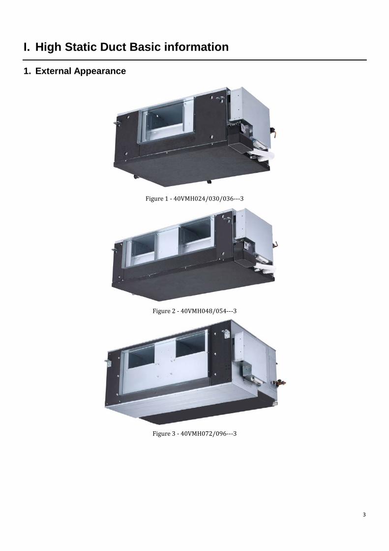
1. External Appearance
Figure 1 - 40VMH024/030/036---3
Figure 2 - 40VMH048/054---3
Figure 3 - 40VMH072/096---3
3
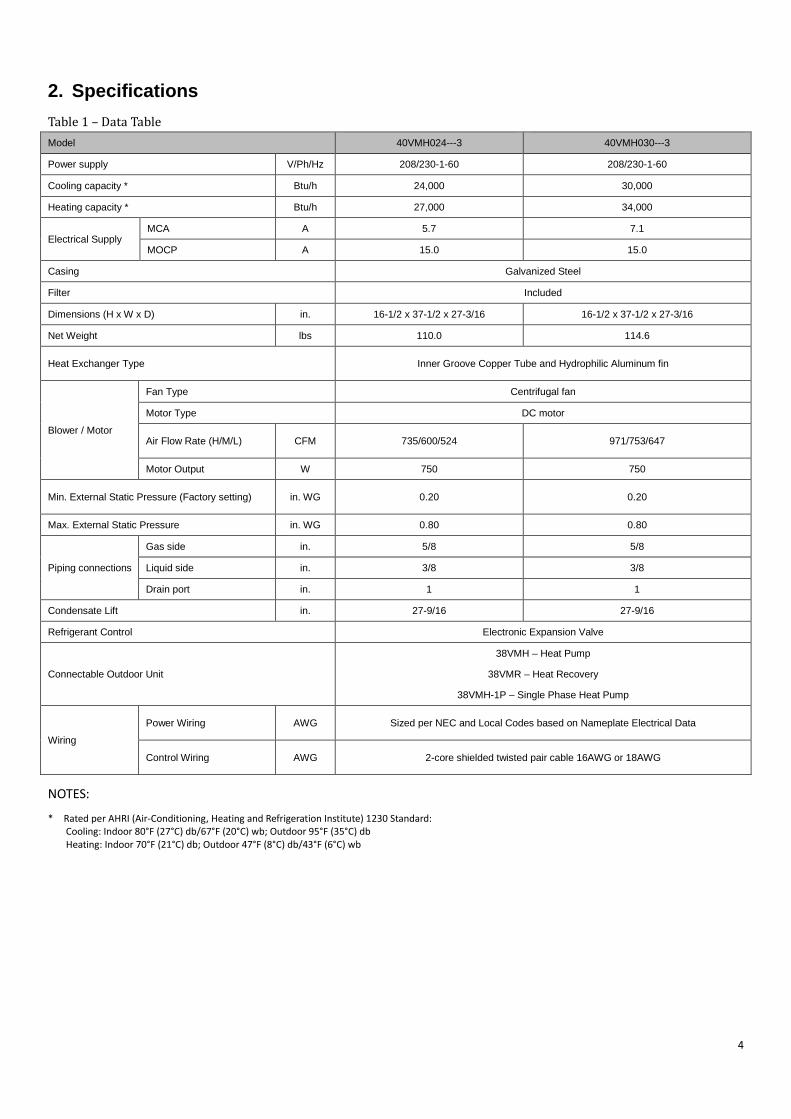
2. Specifications Table 1 – Data Table Model 40VMH024---3 40VMH030---3
Power supply V/Ph/Hz 208/230-1-60 208/230-1-60
Cooling capacity * Btu/h 24,000 30,000
Heating capacity * Btu/h 27,000 34,000
Electrical Supply MCA A 5.7 7.1
MOCP A 15.0 15.0
Casing Galvanized Steel
Filter Included
Dimensions (H x W x D) in. 16-1/2 x 37-1/2 x 27-3/16 16-1/2 x 37-1/2 x 27-3/16
Net Weight lbs 110.0 114.6
Heat Exchanger Type Inner Groove Copper Tube and Hydrophilic Aluminum fin
Blower / Motor
Fan Type Centrifugal fan
Motor Type DC motor
Air Flow Rate (H/M/L) CFM 735/600/524 971/753/647
Motor Output W 750 750
Min. External Static Pressure (Factory setting) in. WG 0.20 0.20
Max. External Static Pressure in. WG 0.80 0.80
Piping connections
Gas side in. 5/8 5/8
Liquid side in. 3/8 3/8
Drain port in. 1 1
Condensate Lift in. 27-9/16 27-9/16
Refrigerant Control Electronic Expansion Valve
Connectable Outdoor Unit
38VMH – Heat Pump
38VMR – Heat Recovery
38VMH-1P – Single Phase Heat Pump
Wiring
Power Wiring AWG Sized per NEC and Local Codes based on Nameplate Electrical Data
Control Wiring AWG 2-core shielded twisted pair cable 16AWG or 18AWG
NOTES:
* Rated per AHRI (Air-Conditioning, Heating and Refrigeration Institute) 1230 Standard: Cooling: Indoor 80°F (27°C) db/67°F (20°C) wb; Outdoor 95°F (35°C) db Heating: Indoor 70°F (21°C) db; Outdoor 47°F (8°C) db/43°F (6°C) wb
4
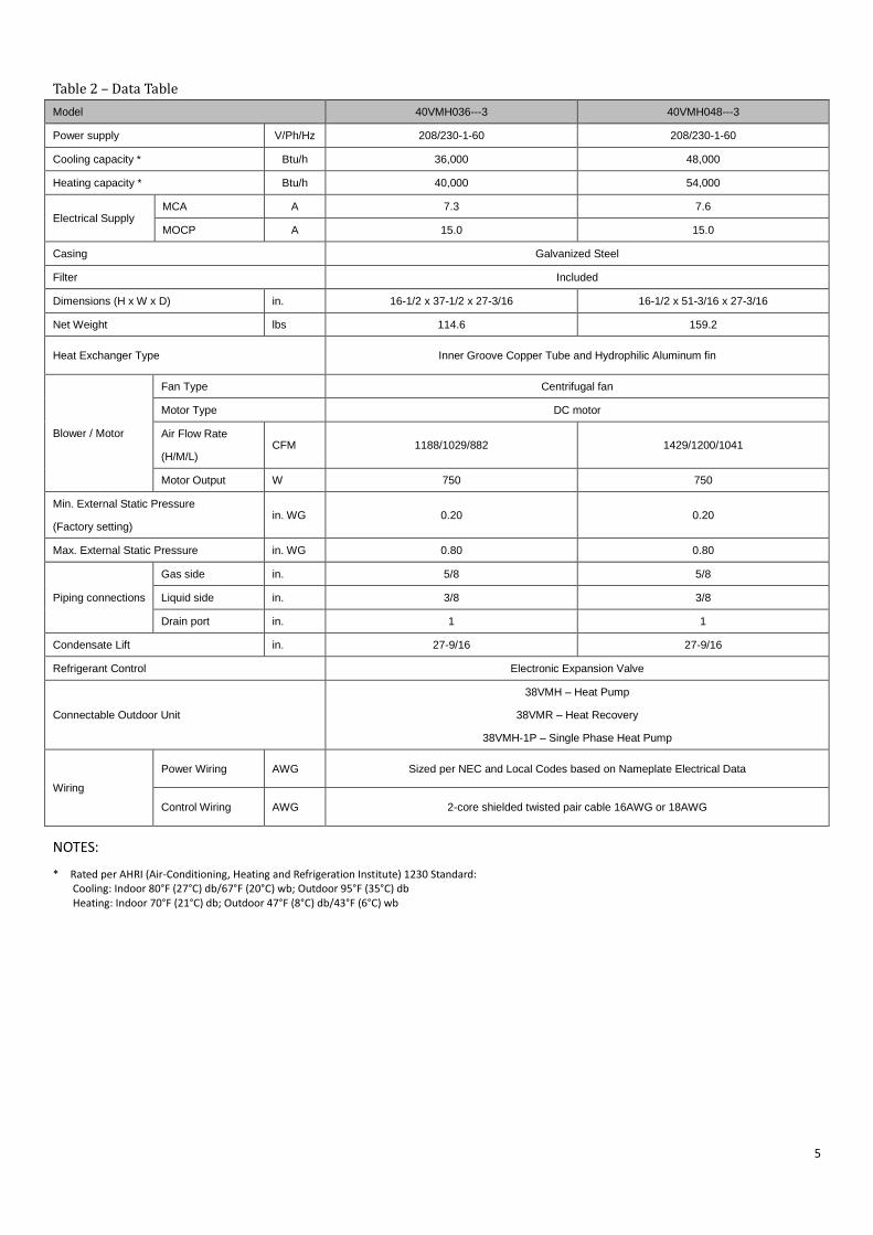
Table 2 – Data Table Model 40VMH036---3 40VMH048---3
Power supply V/Ph/Hz 208/230-1-60 208/230-1-60
Cooling capacity * Btu/h 36,000 48,000
Heating capacity * Btu/h 40,000 54,000
Electrical Supply MCA A 7.3 7.6
MOCP A 15.0 15.0
Casing Galvanized Steel
Filter Included
Dimensions (H x W x D) in. 16-1/2 x 37-1/2 x 27-3/16 16-1/2 x 51-3/16 x 27-3/16
Net Weight lbs 114.6 159.2
Heat Exchanger Type Inner Groove Copper Tube and Hydrophilic Aluminum fin
Blower / Motor
Fan Type Centrifugal fan
Motor Type DC motor
Air Flow Rate
(H/M/L) CFM 1188/1029/882 1429/1200/1041
Motor Output W 750 750
Min. External Static Pressure
(Factory setting) in. WG 0.20 0.20
Max. External Static Pressure in. WG 0.80 0.80
Piping connections
Gas side in. 5/8 5/8
Liquid side in. 3/8 3/8
Drain port in. 1 1
Condensate Lift in. 27-9/16 27-9/16
Refrigerant Control Electronic Expansion Valve
Connectable Outdoor Unit
38VMH – Heat Pump
38VMR – Heat Recovery
38VMH-1P – Single Phase Heat Pump
Wiring
Power Wiring AWG Sized per NEC and Local Codes based on Nameplate Electrical Data
Control Wiring AWG 2-core shielded twisted pair cable 16AWG or 18AWG
NOTES:
* Rated per AHRI (Air-Conditioning, Heating and Refrigeration Institute) 1230 Standard: Cooling: Indoor 80°F (27°C) db/67°F (20°C) wb; Outdoor 95°F (35°C) db Heating: Indoor 70°F (21°C) db; Outdoor 47°F (8°C) db/43°F (6°C) wb
5
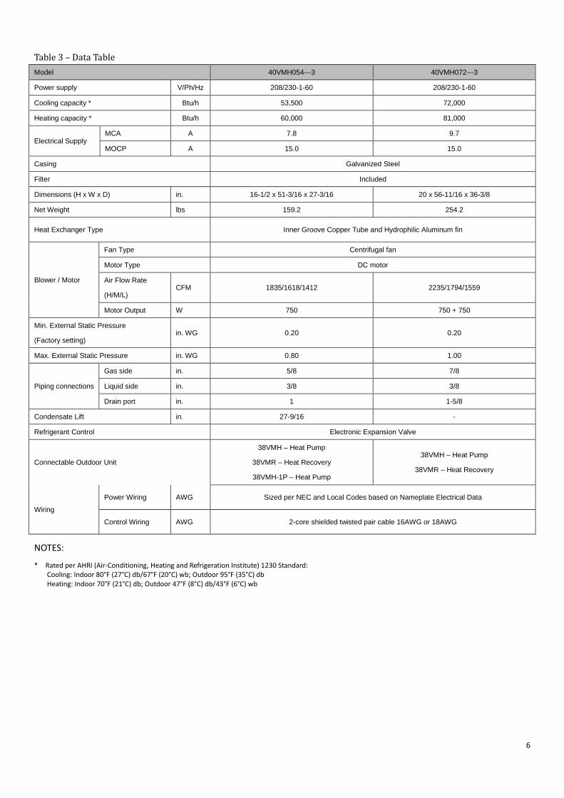
Table 3 – Data Table Model 40VMH054---3 40VMH072---3
Power supply V/Ph/Hz 208/230-1-60 208/230-1-60
Cooling capacity * Btu/h 53,500 72,000
Heating capacity * Btu/h 60,000 81,000
Electrical Supply MCA A 7.8 9.7
MOCP A 15.0 15.0
Casing Galvanized Steel
Filter Included
Dimensions (H x W x D) in. 16-1/2 x 51-3/16 x 27-3/16 20 x 56-11/16 x 36-3/8
Net Weight lbs 159.2 254.2
Heat Exchanger Type Inner Groove Copper Tube and Hydrophilic Aluminum fin
Blower / Motor
Fan Type Centrifugal fan
Motor Type DC motor
Air Flow Rate
(H/M/L) CFM 1835/1618/1412 2235/1794/1559
Motor Output W 750 750 + 750
Min. External Static Pressure
(Factory setting) in. WG 0.20 0.20
Max. External Static Pressure in. WG 0.80 1.00
Piping connections
Gas side in. 5/8 7/8
Liquid side in. 3/8 3/8
Drain port in. 1 1-5/8
Condensate Lift in. 27-9/16 -
Refrigerant Control Electronic Expansion Valve
Connectable Outdoor Unit
38VMH – Heat Pump
38VMR – Heat Recovery
38VMH-1P – Heat Pump
38VMH – Heat Pump
38VMR – Heat Recovery
Wiring
Power Wiring AWG Sized per NEC and Local Codes based on Nameplate Electrical Data
Control Wiring AWG 2-core shielded twisted pair cable 16AWG or 18AWG
NOTES:
* Rated per AHRI (Air-Conditioning, Heating and Refrigeration Institute) 1230 Standard: Cooling: Indoor 80°F (27°C) db/67°F (20°C) wb; Outdoor 95°F (35°C) db Heating: Indoor 70°F (21°C) db; Outdoor 47°F (8°C) db/43°F (6°C) wb
6
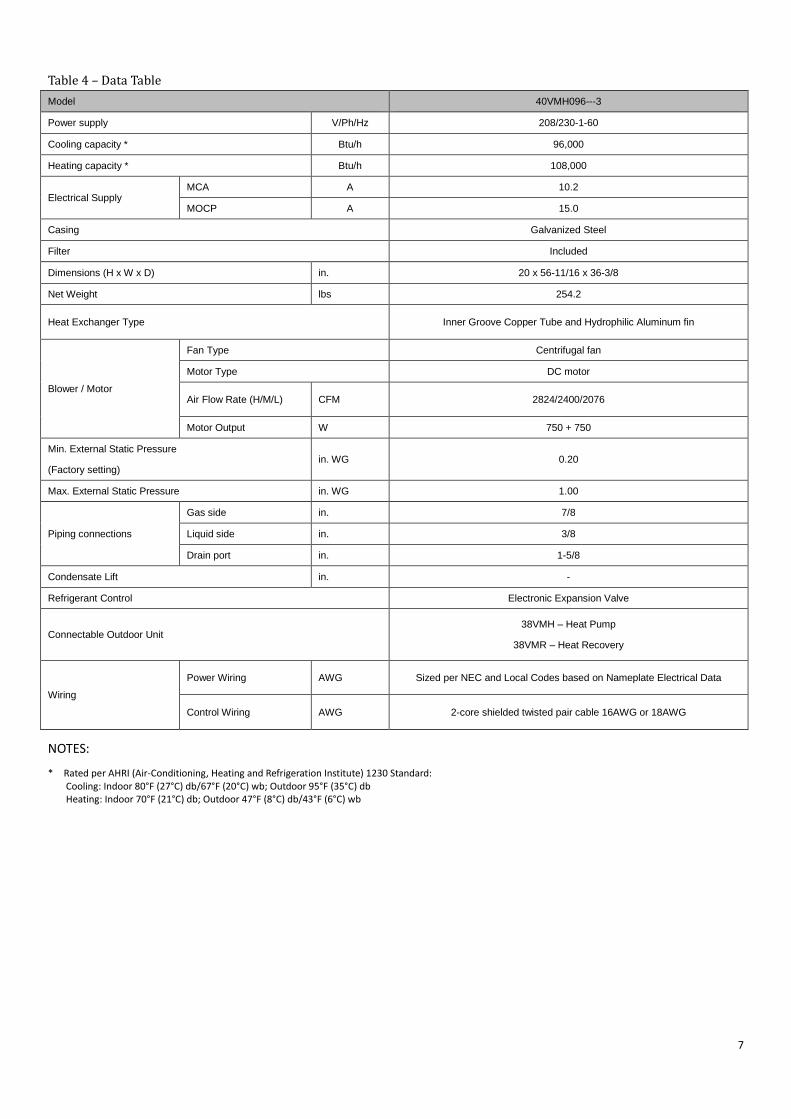
Table 4 – Data Table Model 40VMH096---3
Power supply V/Ph/Hz 208/230-1-60
Cooling capacity * Btu/h 96,000
Heating capacity * Btu/h 108,000
Electrical Supply MCA A 10.2
MOCP A 15.0
Casing Galvanized Steel
Filter Included
Dimensions (H x W x D) in. 20 x 56-11/16 x 36-3/8
Net Weight lbs 254.2
Heat Exchanger Type Inner Groove Copper Tube and Hydrophilic Aluminum fin
Blower / Motor
Fan Type Centrifugal fan
Motor Type DC motor
Air Flow Rate (H/M/L) CFM 2824/2400/2076
Motor Output W 750 + 750
Min. External Static Pressure
(Factory setting) in. WG 0.20
Max. External Static Pressure in. WG 1.00
Piping connections
Gas side in. 7/8
Liquid side in. 3/8
Drain port in. 1-5/8
Condensate Lift in. -
Refrigerant Control Electronic Expansion Valve
Connectable Outdoor Unit 38VMH – Heat Pump
38VMR – Heat Recovery
Wiring
Power Wiring AWG Sized per NEC and Local Codes based on Nameplate Electrical Data
Control Wiring AWG 2-core shielded twisted pair cable 16AWG or 18AWG
NOTES:
* Rated per AHRI (Air-Conditioning, Heating and Refrigeration Institute) 1230 Standard: Cooling: Indoor 80°F (27°C) db/67°F (20°C) wb; Outdoor 95°F (35°C) db Heating: Indoor 70°F (21°C) db; Outdoor 47°F (8°C) db/43°F (6°C) wb
7
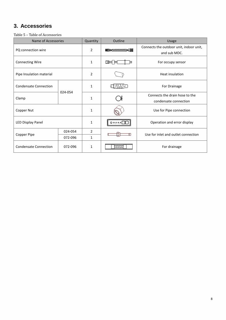
3. Accessories Table 5 – Table of Accessories
Name of Accessories Quantity Outline Usage
PQ connection wire 2 Connects the outdoor unit, indoor unit,
and sub MDC.
Connecting Wire 1 For occupy sensor
Pipe Insulation material 2
Heat insulation
Condensate Connection
024-054
1
For Drainage
Clamp 1
Connects the drain hose to the condensate connection
Copper Nut 1
Use for Pipe connection
LED Display Panel 1
Operation and error display
Copper Pipe 024-054 2
Use for inlet and outlet connection 072-096 1
Condensate Connection 072-096 1 For drainage
8
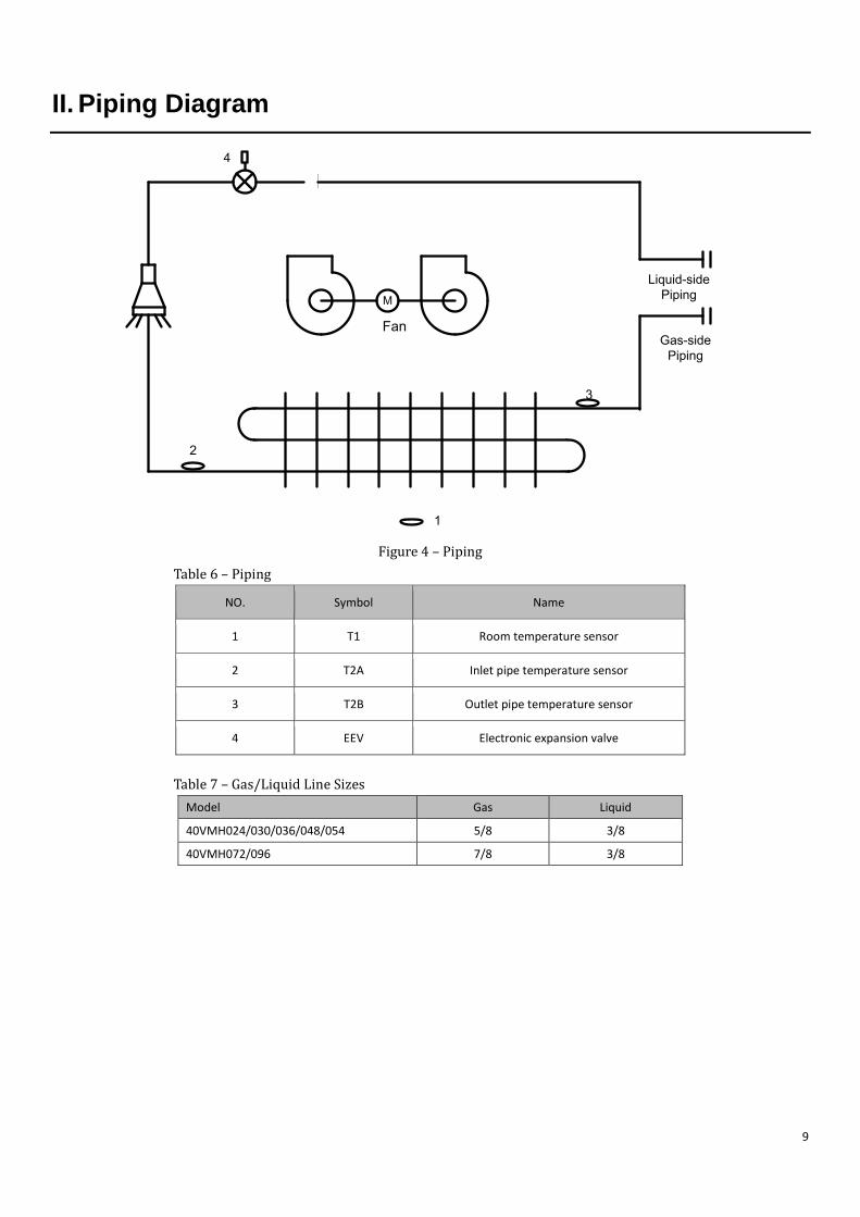
II. Piping Diagram
M
Fan
2
3
4
Gas-side Piping
Liquid-side Piping
1
Figure 4 – Piping Table 6 – Piping
NO. Symbol Name
1 T1 Room temperature sensor
2 T2A Inlet pipe temperature sensor
3 T2B Outlet pipe temperature sensor
4 EEV Electronic expansion valve
Table 7 – Gas/Liquid Line Sizes Model Gas Liquid
40VMH024/030/036/048/054 5/8 3/8
40VMH072/096 7/8 3/8
9
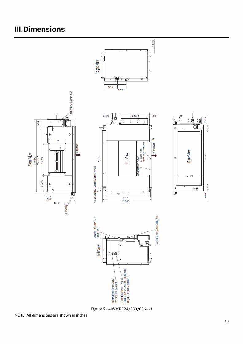
III. Dimensions
Figure 5 - 40VMH024/030/036---3
NOTE: All dimensions are shown in inches. 10

Figure 6 - 40VMH048/054---3 NOTE: All dimensions are shown in inches.
11
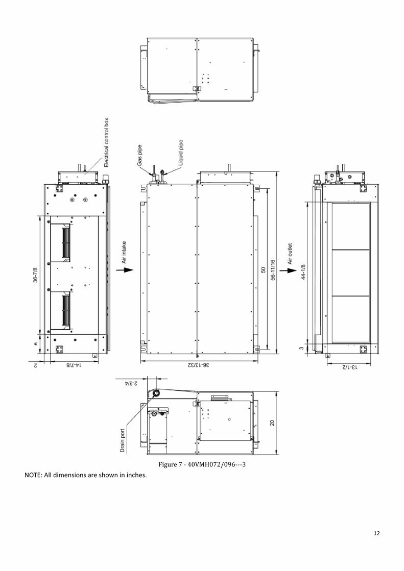
Figure 7 - 40VMH072/096---3
NOTE: All dimensions are shown in inches.
12
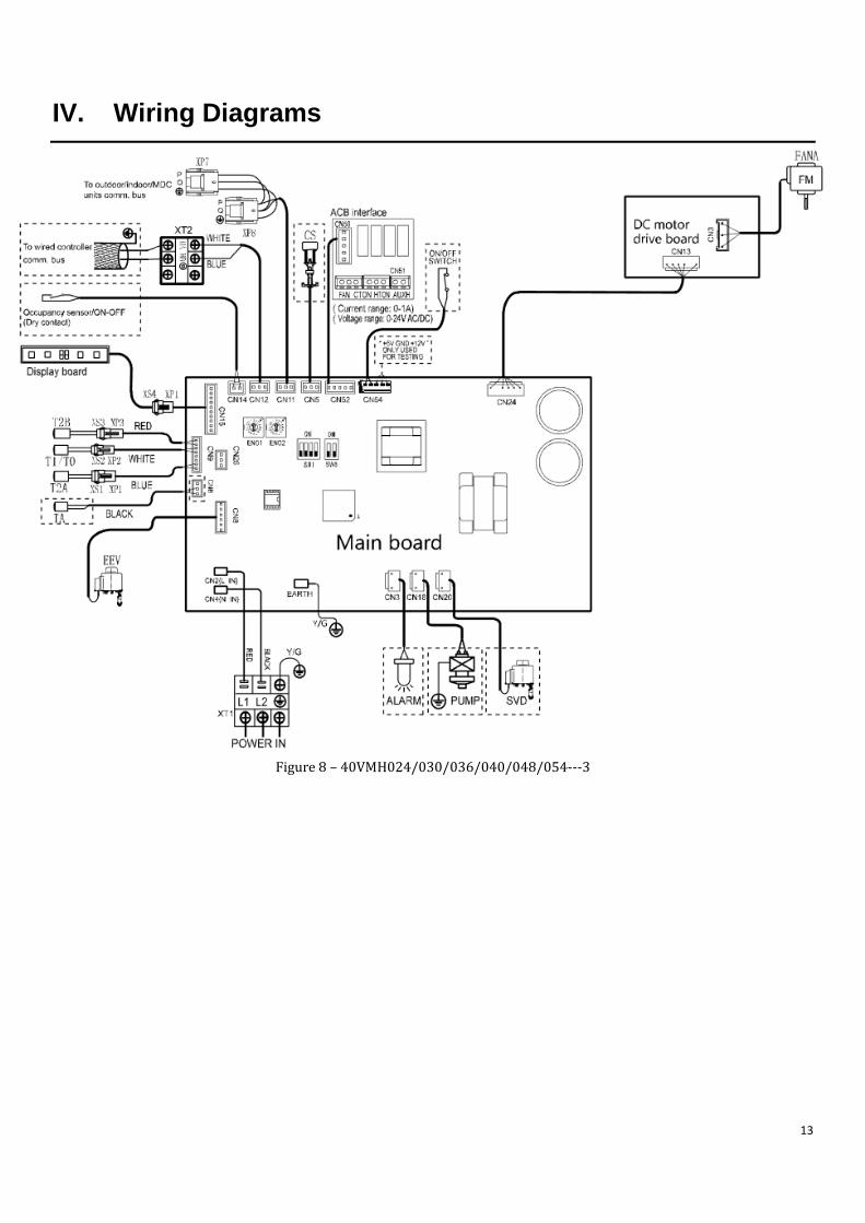
IV. Wiring Diagrams
Figure 8 – 40VMH024/030/036/040/048/054---3
13
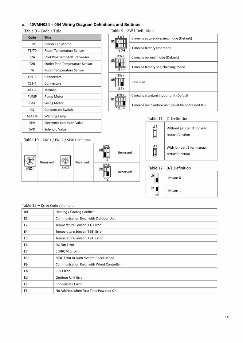
a. 40VMH024 – 054 Wiring Diagram Definitions and Settings
Table 8 – Code / Title Code Title
FM Indoor Fan Motor
T1/T0 Room Temperature Sensor
T2A Inlet Pipe Temperature Sensor
T2B Outlet Pipe Temperature Sensor
TA Room Temperature Sensor
XP1-8 Connectors
XS1-4 Connectors
XT1-2 Terminal
PUMP Pump Motor
GM Swing Motor
CS Condensate Switch
ALARM Warning Lamp
EEV Electronic Extension Valve
SVD Solenoid Valve
Table 9 – SW1 Definition
0 means auto addressing mode (Default)
1 means factory test mode
0 means normal mode (Default)
1 means factory self-checking mode
Reserved
0 means standard indoor unit (Default)
1 means main indoor unit (must be addressed #63)
Table 10 – ENC1 / ENC2 / SW8 Definition
Reserved
Reserved
Reserved
Reserved
Table 11 – J1 Definition
Without jumper J1 for auto
restart function
With jumper J1 for manual
restart function
Table 12 – 0/1 Definition
Means 0
Means 1
Table 13 – Error Code / Content
dd Heating / Cooling Conflict
E1 Communication Error with Outdoor Unit
E2 Temperature Sensor (T1) Error
E4 Temperature Sensor (T2B) Error
E5 Temperature Sensor (T2A) Error
E6 DC Fan Error
E7 EEPROM Error
UU MDC Error in Auto System-Check Mode
E9 Communication Error with Wired Controller
Eb EEV Error
Ed Outdoor Unit Error
EE Condensate Error
FE No Address when First Time Powered On
14
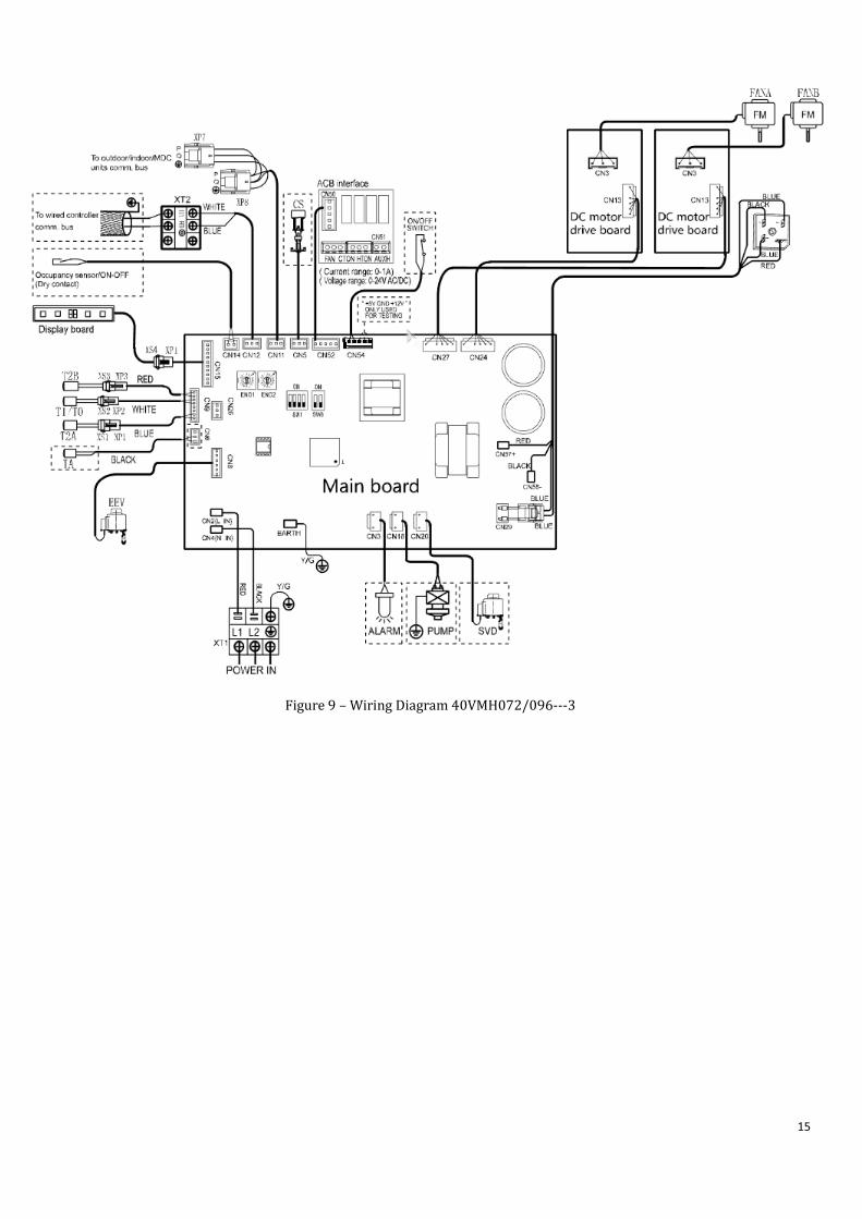
Figure 9 – Wiring Diagram 40VMH072/096---3
15
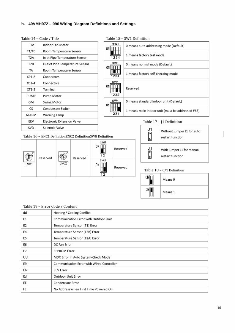
b. 40VMH072 – 096 Wiring Diagram Definitions and Settings
Table 14 – Code / Title
FM Indoor Fan Motor
T1/T0 Room Temperature Sensor
T2A Inlet Pipe Temperature Sensor
T2B Outlet Pipe Temperature Sensor
TA Room Temperature Sensor
XP1-8 Connectors
XS1-4 Connectors
XT1-2 Terminal
PUMP Pump Motor
GM Swing Motor
CS Condensate Switch
ALARM Warning Lamp
EEV Electronic Extension Valve
SVD Solenoid Valve
Table 16 – ENC1 DefinitionENC2 DefinitionSW8 Definition
Reserved
Reserved
Reserved
Reserved
Table 17 – J1 Definition
Without jumper J1 for auto
restart function
With jumper J1 for manual
restart function
Table 18 – 0/1 Definition
Means 0
Means 1
Table 19 – Error Code / Content dd Heating / Cooling Conflict
E1 Communication Error with Outdoor Unit
E2 Temperature Sensor (T1) Error
E4 Temperature Sensor (T2B) Error
E5 Temperature Sensor (T2A) Error
E6 DC Fan Error
E7 EEPROM Error
UU MDC Error in Auto System-Check Mode
E9 Communication Error with Wired Controller
Eb EEV Error
Ed Outdoor Unit Error
EE Condensate Error
FE No Address when First Time Powered On
Table 15 – SW1 Definition
0 means auto addressing mode (Default)
1 means factory test mode
0 means normal mode (Default)
1 means factory self-checking mode
Reserved
0 means standard indoor unit (Default)
1 means main indoor unit (must be addressed #63)
16
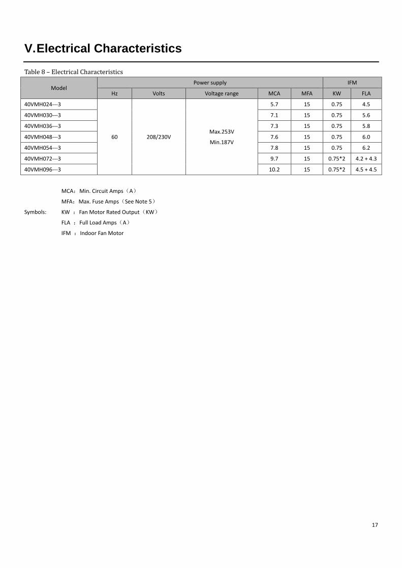
V. Electrical Characteristics
Table 8 – Electrical Characteristics
Model Power supply IFM
Hz Volts Voltage range MCA MFA KW FLA
40VMH024---3
60 208/230V Max.253V
Min.187V
5.7 15 0.75 4.5
40VMH030---3 7.1 15 0.75 5.6
40VMH036---3 7.3 15 0.75 5.8
40VMH048---3 7.6 15 0.75 6.0
40VMH054---3 7.8 15 0.75 6.2
40VMH072---3 9.7 15 0.75*2 4.2 + 4.3
40VMH096---3 10.2 15 0.75*2 4.5 + 4.5
Symbols:
MCA:Min. Circuit Amps(A)
MFA:Max. Fuse Amps(See Note 5)
KW :Fan Motor Rated Output(KW)
FLA :Full Load Amps(A)
IFM :Indoor Fan Motor
17
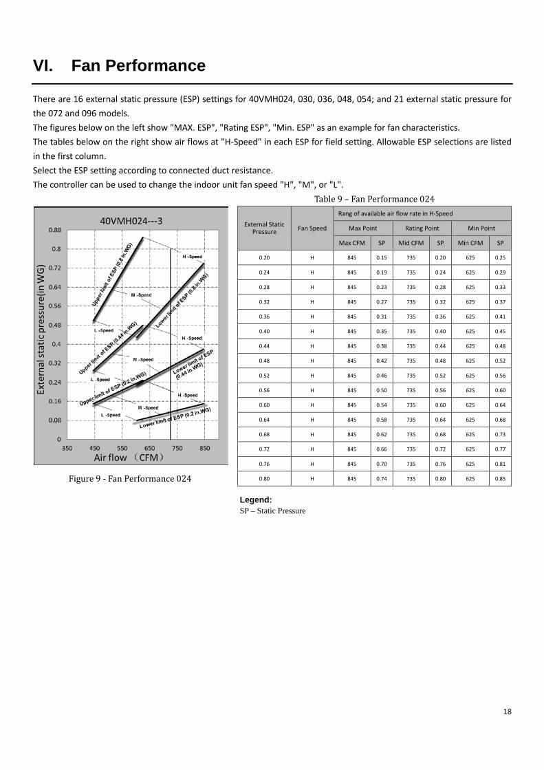
VI. Fan Performance
There are 16 external static pressure (ESP) settings for 40VMH024, 030, 036, 048, 054; and 21 external static pressure for the 072 and 096 models. The figures below on the left show "MAX. ESP", "Rating ESP", "Min. ESP" as an example for fan characteristics. The tables below on the right show air flows at "H-Speed" in each ESP for field setting. Allowable ESP selections are listed in the first column. Select the ESP setting according to connected duct resistance. The controller can be used to change the indoor unit fan speed "H", "M", or "L".
Table 9 – Fan Performance 024
External Static Pressure Fan Speed
Rang of available air flow rate in H-Speed Max Point Rating Point Min Point
Max CFM SP Mid CFM SP Min CFM SP
0.20 H 845 0.15 735 0.20 625 0.25
0.24 H 845 0.19 735 0.24 625 0.29
0.28 H 845 0.23 735 0.28 625 0.33
0.32 H 845 0.27 735 0.32 625 0.37
0.36 H 845 0.31 735 0.36 625 0.41
0.40 H 845 0.35 735 0.40 625 0.45
0.44 H 845 0.38 735 0.44 625 0.48
0.48 H 845 0.42 735 0.48 625 0.52
0.52 H 845 0.46 735 0.52 625 0.56
0.56 H 845 0.50 735 0.56 625 0.60
0.60 H 845 0.54 735 0.60 625 0.64
0.64 H 845 0.58 735 0.64 625 0.68
0.68 H 845 0.62 735 0.68 625 0.73
0.72 H 845 0.66 735 0.72 625 0.77
0.76 H 845 0.70 735 0.76 625 0.81
0.80 H 845 0.74 735 0.80 625 0.85
Figure 9 - Fan Performance 024
Legend: SP – Static Pressure
18
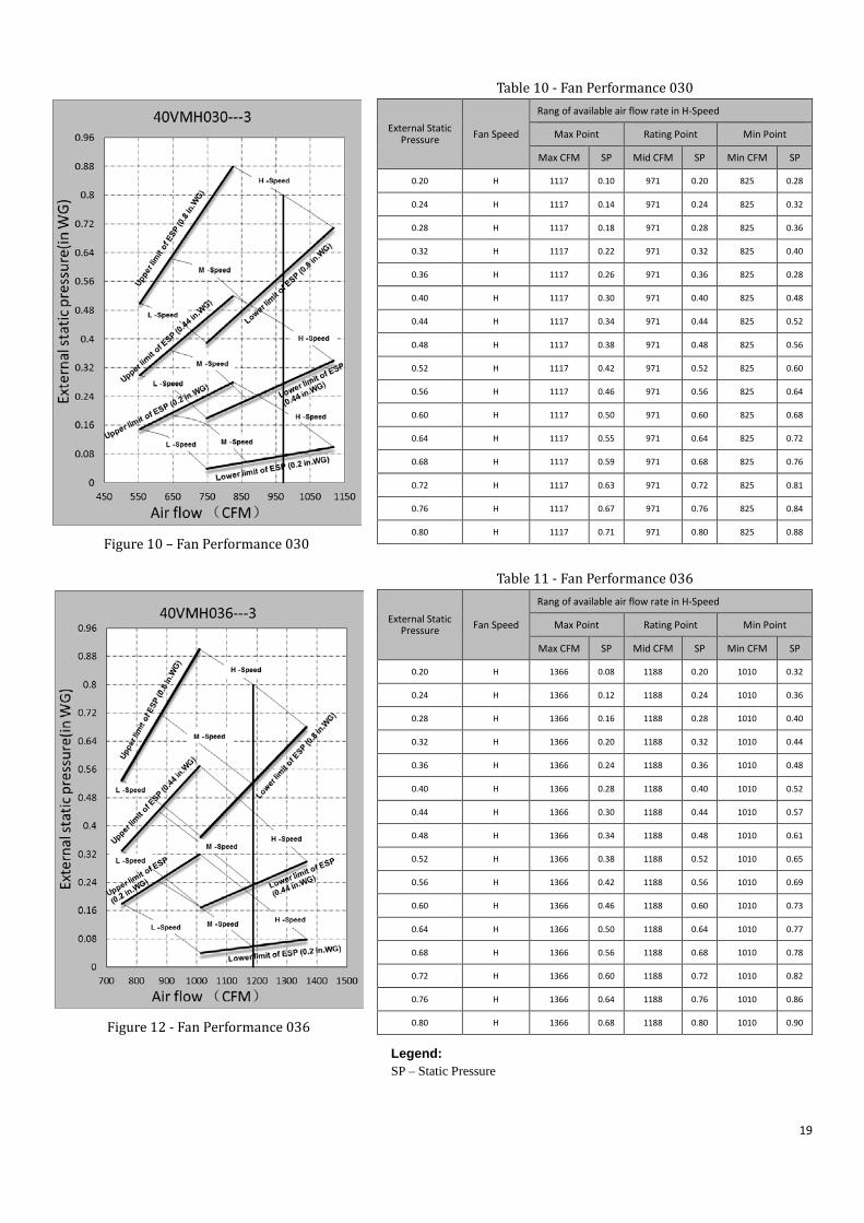
Table 10 - Fan Performance 030
External Static Pressure Fan Speed
Rang of available air flow rate in H-Speed Max Point Rating Point Min Point
Max CFM SP Mid CFM SP Min CFM SP
0.20 H 1117 0.10 971 0.20 825 0.28
0.24 H 1117 0.14 971 0.24 825 0.32
0.28 H 1117 0.18 971 0.28 825 0.36
0.32 H 1117 0.22 971 0.32 825 0.40
0.36 H 1117 0.26 971 0.36 825 0.28
0.40 H 1117 0.30 971 0.40 825 0.48
0.44 H 1117 0.34 971 0.44 825 0.52
0.48 H 1117 0.38 971 0.48 825 0.56
0.52 H 1117 0.42 971 0.52 825 0.60
0.56 H 1117 0.46 971 0.56 825 0.64
0.60 H 1117 0.50 971 0.60 825 0.68
0.64 H 1117 0.55 971 0.64 825 0.72
0.68 H 1117 0.59 971 0.68 825 0.76
0.72 H 1117 0.63 971 0.72 825 0.81
0.76 H 1117 0.67 971 0.76 825 0.84
0.80 H 1117 0.71 971 0.80 825 0.88
Table 11 - Fan Performance 036
External Static Pressure Fan Speed
Rang of available air flow rate in H-Speed Max Point Rating Point Min Point
Max CFM SP Mid CFM SP Min CFM SP
0.20 H 1366 0.08 1188 0.20 1010 0.32
0.24 H 1366 0.12 1188 0.24 1010 0.36
0.28 H 1366 0.16 1188 0.28 1010 0.40
0.32 H 1366 0.20 1188 0.32 1010 0.44
0.36 H 1366 0.24 1188 0.36 1010 0.48
0.40 H 1366 0.28 1188 0.40 1010 0.52
0.44 H 1366 0.30 1188 0.44 1010 0.57
0.48 H 1366 0.34 1188 0.48 1010 0.61
0.52 H 1366 0.38 1188 0.52 1010 0.65
0.56 H 1366 0.42 1188 0.56 1010 0.69
0.60 H 1366 0.46 1188 0.60 1010 0.73
0.64 H 1366 0.50 1188 0.64 1010 0.77
0.68 H 1366 0.56 1188 0.68 1010 0.78
0.72 H 1366 0.60 1188 0.72 1010 0.82
0.76 H 1366 0.64 1188 0.76 1010 0.86
0.80 H 1366 0.68 1188 0.80 1010 0.90
Figure 10 – Fan Performance 030
Figure 12 - Fan Performance 036 Legend: SP – Static Pressure
19
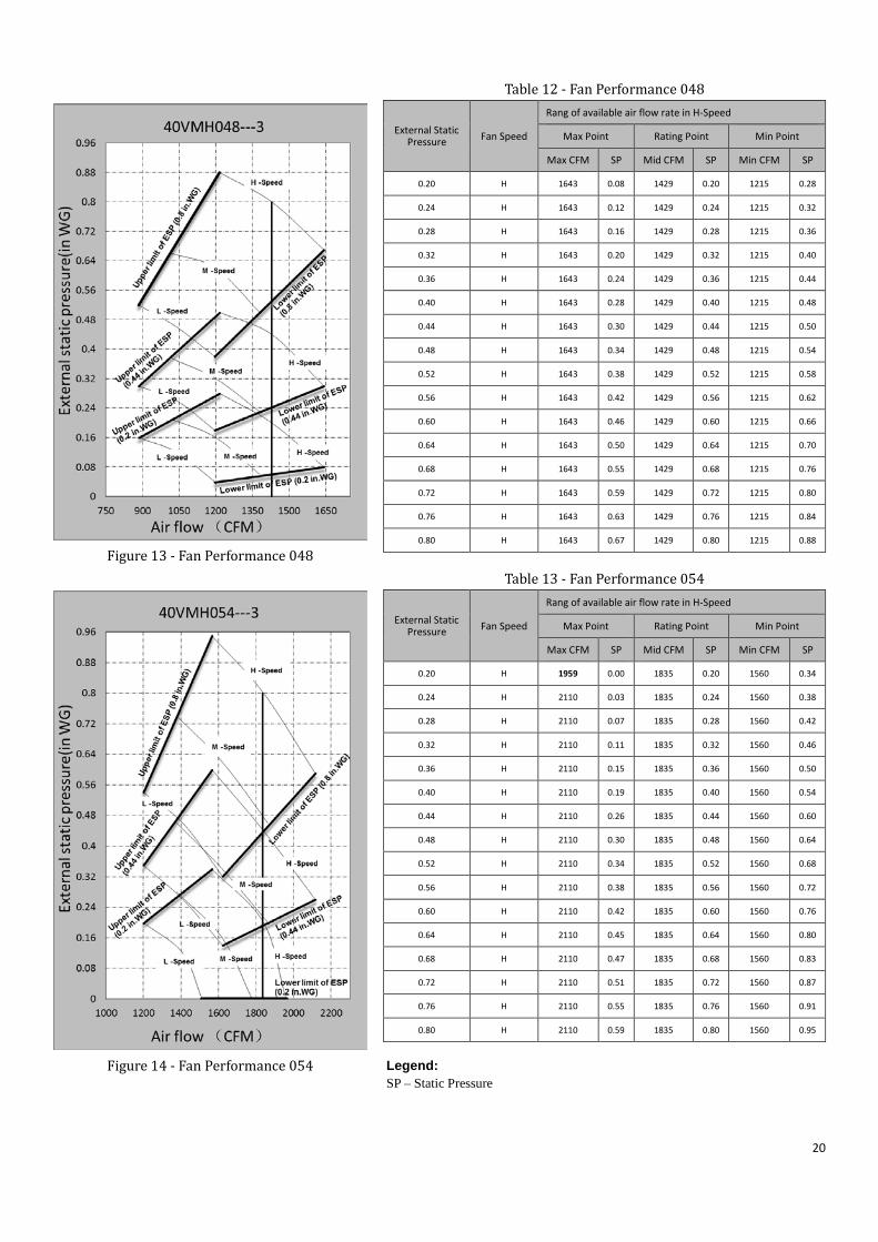
Figure 13 - Fan Performance 048
Table 12 - Fan Performance 048
External Static Pressure Fan Speed
Rang of available air flow rate in H-Speed Max Point Rating Point Min Point
Max CFM SP Mid CFM SP Min CFM SP
0.20 H 1643 0.08 1429 0.20 1215 0.28
0.24 H 1643 0.12 1429 0.24 1215 0.32
0.28 H 1643 0.16 1429 0.28 1215 0.36
0.32 H 1643 0.20 1429 0.32 1215 0.40
0.36 H 1643 0.24 1429 0.36 1215 0.44
0.40 H 1643 0.28 1429 0.40 1215 0.48
0.44 H 1643 0.30 1429 0.44 1215 0.50
0.48 H 1643 0.34 1429 0.48 1215 0.54
0.52 H 1643 0.38 1429 0.52 1215 0.58
0.56 H 1643 0.42 1429 0.56 1215 0.62
0.60 H 1643 0.46 1429 0.60 1215 0.66
0.64 H 1643 0.50 1429 0.64 1215 0.70
0.68 H 1643 0.55 1429 0.68 1215 0.76
0.72 H 1643 0.59 1429 0.72 1215 0.80
0.76 H 1643 0.63 1429 0.76 1215 0.84
0.80 H 1643 0.67 1429 0.80 1215 0.88
Figure 14 - Fan Performance 054
Table 13 - Fan Performance 054
External Static Pressure Fan Speed
Rang of available air flow rate in H-Speed Max Point Rating Point Min Point
Max CFM SP Mid CFM SP Min CFM SP
0.20 H 1959 0.00 1835 0.20 1560 0.34
0.24 H 2110 0.03 1835 0.24 1560 0.38
0.28 H 2110 0.07 1835 0.28 1560 0.42
0.32 H 2110 0.11 1835 0.32 1560 0.46
0.36 H 2110 0.15 1835 0.36 1560 0.50
0.40 H 2110 0.19 1835 0.40 1560 0.54
0.44 H 2110 0.26 1835 0.44 1560 0.60
0.48 H 2110 0.30 1835 0.48 1560 0.64
0.52 H 2110 0.34 1835 0.52 1560 0.68
0.56 H 2110 0.38 1835 0.56 1560 0.72
0.60 H 2110 0.42 1835 0.60 1560 0.76
0.64 H 2110 0.45 1835 0.64 1560 0.80
0.68 H 2110 0.47 1835 0.68 1560 0.83
0.72 H 2110 0.51 1835 0.72 1560 0.87
0.76 H 2110 0.55 1835 0.76 1560 0.91
0.80 H 2110 0.59 1835 0.80 1560 0.95
Legend: SP – Static Pressure
20
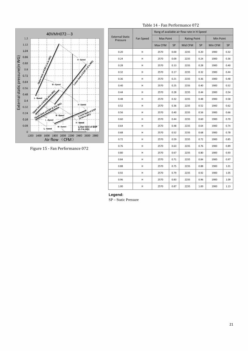
Table 14 - Fan Performance 072
External Static Pressure Fan Speed
Rang of available air flow rate in H-Speed Max Point Rating Point Min Point
Max CFM SP Mid CFM SP Min CFM SP
0.20 H 2570 0.00 2235 0.20 1900 0.32
0.24 H 2570 0.09 2235 0.24 1900 0.36
0.28 H 2570 0.13 2235 0.28 1900 0.40
0.32 H 2570 0.17 2235 0.32 1900 0.44
0.36 H 2570 0.21 2235 0.36 1900 0.48
0.40 H 2570 0.25 2235 0.40 1900 0.52
0.44 H 2570 0.28 2235 0.44 1900 0.54
0.48 H 2570 0.32 2235 0.48 1900 0.58
0.52 H 2570 0.36 2235 0.52 1900 0.62
0.56 H 2570 0.40 2235 0.56 1900 0.66
0.60 H 2570 0.44 2235 0.60 1900 0.70
0.64 H 2570 0.48 2235 0.64 1900 0.74
0.68 H 2570 0.52 2235 0.68 1900 0.78
0.72 H 2570 0.59 2235 0.72 1900 0.85
0.76 H 2570 0.63 2235 0.76 1900 0.89
0.80 H 2570 0.67 2235 0.80 1900 0.93
0.84 H 2570 0.71 2235 0.84 1900 0.97
0.88 H 2570 0.75 2235 0.88 1900 1.01
0.92 H 2570 0.79 2235 0.92 1900 1.05
0.96 H 2570 0.83 2235 0.96 1900 1.09
1.00 H 2570 0.87 2235 1.00 1900 1.13
Figure 15 - Fan Performance 072
Legend: SP – Static Pressure
21
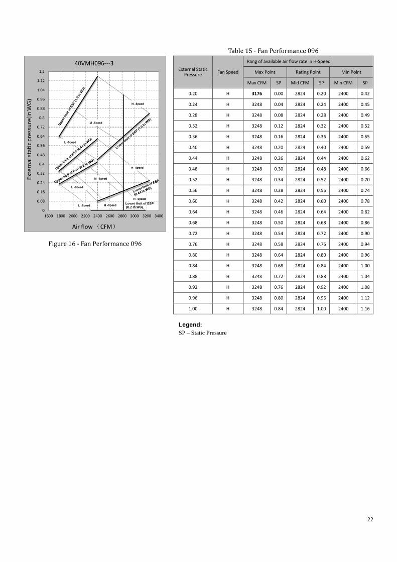
Figure 16 - Fan Performance 096
Table 15 - Fan Performance 096
External Static Pressure Fan Speed
Rang of available air flow rate in H-Speed Max Point Rating Point Min Point
Max CFM SP Mid CFM SP Min CFM SP
0.20 H 3176 0.00 2824 0.20 2400 0.42
0.24 H 3248 0.04 2824 0.24 2400 0.45
0.28 H 3248 0.08 2824 0.28 2400 0.49
0.32 H 3248 0.12 2824 0.32 2400 0.52
0.36 H 3248 0.16 2824 0.36 2400 0.55
0.40 H 3248 0.20 2824 0.40 2400 0.59
0.44 H 3248 0.26 2824 0.44 2400 0.62
0.48 H 3248 0.30 2824 0.48 2400 0.66
0.52 H 3248 0.34 2824 0.52 2400 0.70
0.56 H 3248 0.38 2824 0.56 2400 0.74
0.60 H 3248 0.42 2824 0.60 2400 0.78
0.64 H 3248 0.46 2824 0.64 2400 0.82
0.68 H 3248 0.50 2824 0.68 2400 0.86
0.72 H 3248 0.54 2824 0.72 2400 0.90
0.76 H 3248 0.58 2824 0.76 2400 0.94
0.80 H 3248 0.64 2824 0.80 2400 0.96
0.84 H 3248 0.68 2824 0.84 2400 1.00
0.88 H 3248 0.72 2824 0.88 2400 1.04
0.92 H 3248 0.76 2824 0.92 2400 1.08
0.96 H 3248 0.80 2824 0.96 2400 1.12
1.00 H 3248 0.84 2824 1.00 2400 1.16
Legend: SP – Static Pressure
22
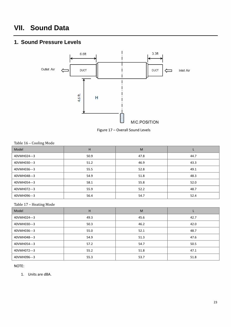
VII. Sound Data
1. Sound Pressure Levels
Figure 17 – Overall Sound Levels
Table 16 – Cooling Mode Model H M L
40VMH024---3 50.9 47.8 44.7
40VMH030---3 51.2 46.9 43.3
40VMH036---3 55.5 52.8 49.1
40VMH048---3 54.9 51.8 48.3
40VMH054---3 58.1 55.8 52.0
40VMH072---3 55.9 52.2 48.7
40VMH096---3 56.4 54.7 52.4
Table 17 – Heating Mode Model H M L
40VMH024---3 49.3 45.6 42.7
40VMH030---3 50.3 46.2 42.0
40VMH036---3 55.0 52.1 48.7
40VMH048---3 54.9 51.3 47.6
40VMH054---3 57.2 54.7 50.5
40VMH072---3 55.2 51.8 47.1
40VMH096---3 55.3 53.7 51.8
NOTE:
1. Units are dBA.
23
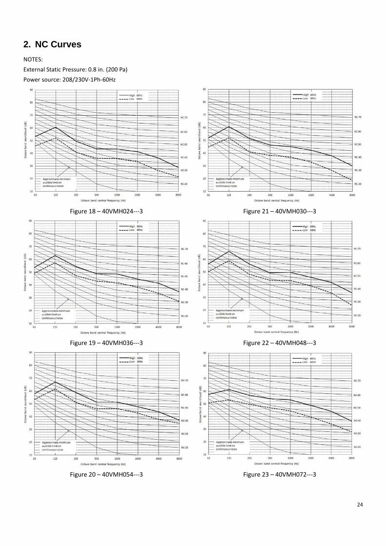
2. NC Curves NOTES: External Static Pressure: 0.8 in. (200 Pa) Power source: 208/230V-1Ph-60Hz
Figure 18 – 40VMH024---3 Figure 21 – 40VMH030---3
Figure 19 – 40VMH036---3 Figure 22 – 40VMH048---3
Figure 20 – 40VMH054---3 Figure 23 – 40VMH072---3
24
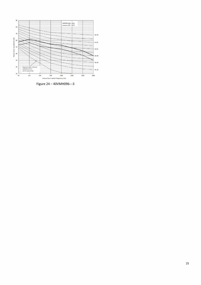
Figure 24 – 40VMH096---3
25
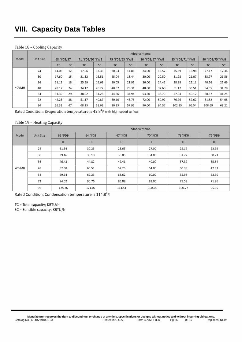
VIII. Capacity Data Tables Table 18 – Cooling Capacity
Model Unit Size
Indoor air temp.
68 ℉DB/57
71 ℉DB/60 ℉WB 75 ℉DB/63 ℉WB 80 ℉DB/67 ℉WB 85 ℉DB/71 ℉WB 90 ℉DB/75 ℉WB
TC SC TC SC TC SC TC SC TC SC TC SC
40VMH
24 14.08 12.
17.06 13.33 20.03 14.88 24.00 16.52 25.59 16.98 27.17 17.36
30 17.60 15.
21.32 16.51 25.04 18.44 30.00 20.50 31.98 21.07 33.97 21.56
36 21.12 18.
25.59 19.63 30.05 21.95 36.00 24.42 38.38 25.11 40.76 25.69
48 28.17 24.
34.12 26.22 40.07 29.31 48.00 32.60 51.17 33.51 54.35 34.28
54 31.39 29.
38.02 31.26 44.66 34.94 53.50 38.79 57.04 40.12 60.57 41.25
72 42.25 38.
51.17 40.87 60.10 45.76 72.00 50.92 76.76 52.62 81.52 54.08
96 56.33 47.
68.23 51.63 80.13 57.92 96.00 64.57 102.35 66.54 108.69 68.21
Rated Condition: Evaporation temperature is 42.8°F with high speed airflow.
Table 19 – Heating Capacity
Model Unit Size
Indoor air temp.
62 ℉DB 64 ℉DB 67 ℉DB 70 ℉DB 73 ℉DB 75 ℉DB
TC TC TC TC TC TC
40VMH
24 31.34 30.25 28.63 27.00 25.19 23.99
30 39.46 38.10 36.05 34.00 31.72 30.21
36 46.43 44.82 42.41 40.00 37.32 35.54
48 62.68 60.51 57.25 54.00 50.38 47.97
54 69.64 67.23 63.62 60.00 55.98 53.30
72 94.02 90.76 85.88 81.00 75.58 71.96
96 125.36 121.02 114.51 108.00 100.77 95.95
Rated Condition: Condensation temperature is 114.8°F. TC = Total capacity; KBTU/h SC = Sensible capacity; KBTU/h
Manufacturer reserves the right to discontinue, or change at any time, specifications or designs without notice and without incurring obligations.
Catalog No. 17-40VMH001-03 Printed in U.S.A. Form 40VMH-1ED Pg 26 06-17 Replaces: NEW
Top Related