


Languages
Pages
Legal


Electrical Safety Introduction to Aerial Lines Ezekiel Enterprises, LLC
Electrical Safety Introduction to
Aerial Lines Course# EE710
EZ-pdh.com Ezekiel Enterprises, LLC
301 Mission Dr. Unit 571 New Smyrna Beach, FL 32128
386-882-EZCE(3923) [email protected]

Electrical Safety Introduction to Aerial Lines Ezekiel Enterprises, LLC
1 | P a g e
Table of Contents
1 Aerial Line work. ........................................................................................................................................ 4
1.1 Working in Elevated Positions. ........................................................................................................... 4
1.2 Qualified Climber. ............................................................................................................................... 4
1.3 Criteria for Qualified Climbers. ........................................................................................................... 4
2 Pole Handling Operations. ......................................................................................................................... 5
2.1 General. ............................................................................................................................................... 5
2.2 Pole Contact Precautions. ................................................................................................................... 5
2.3 Receiving Pole Shipment. .................................................................................................................... 5
2.4 Ground Handling ................................................................................................................................. 6
2.5 Long Term Pole Storage. ..................................................................................................................... 7
2.6 Temporary Pole Storage. .................................................................................................................... 7
2.7 Hauling Poles ....................................................................................................................................... 7
3 Pole Installation, Replacement, And Removal. .......................................................................................... 8
3.1 Pole Holes. .......................................................................................................................................... 8
3.2 Digging Holes....................................................................................................................................... 8
3.3 Covering a Hole. .................................................................................................................................. 8
3.4 Hole Casings. ....................................................................................................................................... 8
3.5 Setting Poles. ....................................................................................................................................... 8
3.5.1 Pike Pole Method. ............................................................................................................................ 8
3.6 Pole Setting Trucks. ........................................................................................................................... 11
3.7 Setting Poles in Energized Lines. ....................................................................................................... 12
3.8 Backfilling the Hole. .......................................................................................................................... 12
3.9 Dismantling Poles. ............................................................................................................................. 12
4 Climbing and Working on Poles. .............................................................................................................. 13
4.1 General Rules. ................................................................................................................................... 13
4.2 Pole Inspection Before Climbing. ...................................................................................................... 14
5 Pole Climbing Equipment. ........................................................................................................................ 15
5.1 General Rules. ................................................................................................................................... 15

Electrical Safety Introduction to Aerial Lines Ezekiel Enterprises, LLC
2 | P a g e
5.2 Wooden Pole Climbing Equipment. .................................................................................................. 15
5.3 Concrete and Steel Pole Climbing. .................................................................................................... 20
6 Pole Climbing and Work Precautions. ...................................................................................................... 21
6.1 General Pole Climbing Precautions. .................................................................................................. 21
6.2 Wooden Pole Climbing Precautions. ................................................................................................. 22
6.3 Concrete and Steel Pole and Tower Climbing Precautions. .............................................................. 22
6.4 Working on Poles. ............................................................................................................................. 23
6.5 Safety Straps. .................................................................................................................................... 23
6.6 Hoisting or Lowering Materials. ........................................................................................................ 23
7 Crossing Structures. ................................................................................................................................. 24
8 Stringing Or Removing De-energized Conductors And Overhead Ground Wires. ................................... 24
8.1 Pre-Work Meeting. ........................................................................................................................... 24
8.2 Work Adjacent to Energized Lines. ................................................................................................... 24
8.3 Grounding. ........................................................................................................................................ 25
8.4 Handling and Stringing. ..................................................................................................................... 25
8.5 Primary Line Installation. .................................................................................................................. 26
8.6 Secondary Line Installation. .............................................................................................................. 27
8.7 Removing Lines. ................................................................................................................................ 27
8.8 Guying. .............................................................................................................................................. 27
8.9 Insulators........................................................................................................................................... 28
9 Energized Work. ....................................................................................................................................... 28
10 Street Lighting. ....................................................................................................................................... 28
10.1 Voltage Level. .................................................................................................................................. 28
10.2 Clearance Requirements. ................................................................................................................ 28
10.3 Multiple Street Lighting Circuits. .................................................................................................... 28
10.4 Series Street Lighting Circuits. ........................................................................................................ 29
10.5 Climbing Space. ............................................................................................................................... 29
10.6 Time Switches. ................................................................................................................................ 29
11 Working On or Near Pole-Mounted Equipment. ................................................................................... 29
11.1 Surge Arresters. .............................................................................................................................. 29
11.2 Switches and Fuses. ........................................................................................................................ 29
11.3 Capacitors. ...................................................................................................................................... 30

Electrical Safety Introduction to Aerial Lines Ezekiel Enterprises, LLC
3 | P a g e
11.4 Power Transformers and Voltage Regulators. ................................................................................ 30
12 Aerial Rope. ............................................................................................................................................ 31
12.1 Conductivity. ................................................................................................................................... 31
12.2 Terminology of Rope Use. ............................................................................................................... 31
12.3 Knots and Splices. ........................................................................................................................... 32
12.4 Handline and Rope Line Precautions. ............................................................................................. 32
12.5 Tackle Blocks. .................................................................................................................................. 33
13 Tools. ...................................................................................................................................................... 33
13.1 Portable Power Tool Precautions ................................................................................................... 33
13.2 Miscellaneous Tool Precautions. .................................................................................................... 33
14 Aerial Lifts and Insulated Buckets. ......................................................................................................... 34
14.1 Types of Aerial Lifts. ........................................................................................................................ 34
14.2 General Requirements. ................................................................................................................... 38
14.3 Training ........................................................................................................................................... 40
14.4 Driving Precautions. ........................................................................................................................ 40
14.5 Setting Up and Knocking Down at the Job Site. .............................................................................. 40
14.6 Operating at the Job Site. ............................................................................................................... 41
14.7 Operation of Aerial Lift Equipment Near Energized Electrical Facilities. ........................................ 43
15 Tree Trimming and Brush Removal ........................................................................................................ 43
15.1 Training Qualifications. ................................................................................................................... 43
15.2 Public Safety. ................................................................................................................................... 43
15.3 Tool Safety. ..................................................................................................................................... 44
15.4 Work Near Energized Lines. ............................................................................................................ 44
15.5 Climbing and Working on Trees. ..................................................................................................... 44
15.6 Felling Trees. ................................................................................................................................... 45
15.7 Power Trimming Equipment. .......................................................................................................... 45
15.8 Right-Of-Way Brush Removal. ........................................................................................................ 46
REFERENCES ................................................................................................................................................ 47

Electrical Safety Introduction to Aerial Lines Ezekiel Enterprises, LLC
4 | P a g e
ELECTRICAL SAFETY – AERIAL LINES
1 Aerial Line work. This course includes specific requirements for poles and structures, pole-
mounted equipment, and aerial lines. Requirements addressed include pole handling and
erection, climbing and working on poles, stringing of lines, working around pole-mounted
lighting and other equipment, tool handling, and tree and brush trimming adjacent to an aerial
line right-of-way.
1.1 Working in Elevated Positions. Additional safety requirements are needed for aerial line
work since climbing poles is often necessary. Not all work can be accomplished from aerial lifts.
Electrical workers must both recognize electrical hazards, and be trained how to prevent falls.
This includes training in safe climbing procedures when the structure design cannot
accommodate optimum fall protection load requirements.
1.2 Qualified Climber. Only workers who meet “Qualified Climber” requirements are permitted
to do work requiring climbing poles or trees./2/ Each activity must establish these requirements
for both activity personnel and contract personnel. They must apply to all persons whose work
involves climbing.
1.3 Criteria for Qualified Climbers. Comply with the requirements of OSHA 29 CFR
1910.269 (q) “Overhead Lines.” The majority of the work will be done in an elevated position
above ground level. Climbing aerial line structures such as poles may be required. Situations
with limited structure access can prevent use of an aerial lift bucket truck. The structure design
may not accommodate positive fall protection load requirements. Only workers who meet
"Qualified Climber" requirements are permitted to do work which requires climbing poles or
trees. Each activity should establish “qualified climber” requirements both for activity personnel
and for contract personnel, including the following:
• Physical fitness required for climbing should be documented not only by an annual
physical, but also be validated by supervisory observation.
• Climbing duties should be a part of routine job activities, not an occasional occurrence.
• A minimum of 2 years of documented climbing training should be completed.
Experience should include hazard recognition and hands-on-training incorporating
appropriate safe climbing practices and rescue training.

Electrical Safety Introduction to Aerial Lines Ezekiel Enterprises, LLC
5 | P a g e
• Demonstrated proficiency is required on structure types similar to those that are to be
climbed and should show that these structures have been climbed on a routine basis
within the last 5 years.
• A worker in training may function as qualified only when working under the direct
supervision and observation of a "Qualified Climber."
2 Pole Handling Operations. Precautions are necessary in handling poles safely. Poles are long,
heavy, and treated with potentially hazardous pesticides and preservatives. They pose hazards to
the workers involved in installation and dismantling operations. Additionally, mistreatment of
poles during installation may degrade their ability to meet service requirements, and could
endanger those workers who climb them.
2.1 General. The authorized individual-in-charge must either do it themselves or assign a crew
member to direct the handling of poles and give all signals when poles are being lifted or
handled. Poles must, whenever possible, be handled starting from the top and the end of the
stack. Workers must roll poles away from them using cant hooks or bars. Poles must not be
caught with cant hooks while in motion. Whenever possible, carrying hooks must be used when
carrying poles.
2.2 Pole Contact Precautions.
WARNING
Creosote, which is applied to poles as a preservative, can cause skin burns on contact. The
following precautions must be taken to avoid burns:
2.2.1 Keep arms covered with long sleeved shirts when handling poles.
2.2.2 Always wear gloves.
2.2.3 Keep neck well covered with a collar or a handkerchief.
2.2.4 Keep trousers as long as practical to protect ankles.
2.2.5 Never rub eyes or wipe perspiration from face using hands or shirtsleeves after they have
been exposed to creosote.
2.2.6 Protect hands, arms, and face with a preparation made up of one part gum acacia or gum
tragacanth, and three parts lanolin where direct contact with creosote is likely to occur. If this
preparation cannot be obtained, acceptable protection can be provided by petroleum jelly (such
as Vaseline™). First aid treatment must be obtained immediately when bare skin or eyes come in
contact with creosote.
2.3 Receiving Pole Shipment. Poles are usually shipped to an activity’s pole storage yard using
flatbed railway cars, on which they are secured with skids, stakes, slings, and binding. Removal
is safe if done properly. The principal objectives are to unload poles so that none are broken, and
so that the poles do not roll onto any worker.

Electrical Safety Introduction to Aerial Lines Ezekiel Enterprises, LLC
6 | P a g e
2.3.1 Skids, rope lines, and slings must preferably be 1/2 in or 5/8 in (12.5 to 16 mm) wire rope.
These must be inspected to ensure they are in satisfactory condition for the operation.
2.3.2 All binding wire, stakes, and other fastenings must be inspected for weak or broken areas
before unloading.
2.3.3 Always preposition lines as necessary to restrain loads when stakes and binding wires are
cut.
2.3.4 The authorized individual-in-charge must determine that all workers are safely in the clear
before permitting binders or stakes to be cut.
2.3.5 Binding wires must be cut with long-handled wire cutters. Never cut binders from the top
of the load.
2.3.6 Only one person must be permitted on top of a loaded car at a time. No one must be
allowed on top of a carload of poles to cut wires, or if any wires or braces have been cut or
removed.
2.4 Ground Handling. Once on the ground the poles can be positioned by the use of cant hooks.
Special precautions must be taken while using these hooks:
2.4.1 Hooks must be kept sharp, and must be protected when not in use.
2.4.2 The hook bolt must be inspected periodically for wear. If a worn hook bolt breaks in use,
sudden and possibly severe injuries could result.
2.4.3 Injuries most often occur when a pole handle breaks or the hook comes out. Be sure the
hook is firmly set in the pole.
2.4.4 The cant hook is a one-worker tool. It is likely to break if two workers double up. If a job
requires two workers, two cant hooks must be used.
2.4.5 Before moving the pole, make sure that there are no tripping hazards near the workers.
2.4.6 Stand so the pole is rolled away. Pulling the pole allows the pole to roll on a foot or crush a
leg.
2.4.7 Be particularly careful if the pole is rolled over a hump, since the pole could roll back when
the grip and position of the hook is changed.
2.4.8 When moving a pole by hand, with a pole cart, or with the truck derrick, warn anyone
nearby who could possibly be struck. Station a worker with a red flag to warn or stop traffic, if
necessary.

Electrical Safety Introduction to Aerial Lines Ezekiel Enterprises, LLC
7 | P a g e
2.5 Long Term Pole Storage.
2.5.1 Poles that are stored for considerable periods must be stacked above the ground on racks.
The racks must provide ventilation, and properly block the poles to keep them from shifting or
rolling.
2.5.2 Never store poles with cross-arms, braces, steps, or hardware attached.
2.5.3 Poles must be stored according to size, and to make them as accessible as possible.
2.5.4 Maintain an area around stored poles of at least 10 ft (3.0 m) free of grass and weeds.
Provide sufficient space under poles to permit removal of leaves and debris.
2.6 Temporary Pole Storage.
2.6.1 Poles stored temporarily on or near roadways, before erection or removal, must be placed
as close as possible to the curb or edge of roadway as is safe; however; never store poles at
points along the road where there are sharp turns. Do not place the poles where they interfere
with traffic, driveways, or walkways.
2.6.2 Place each pole so that its top points in the direction of traffic. Poles temporarily stored
along side highways must not have crossarms attached.
2.6.3 When laid on an incline, poles must not be placed where they can interfere with drainage.
2.6.4 The authorized individual-in-charge must decide whether danger signs (by day) or red
lights (at night) are required.
2.7 Hauling Poles. Pole hauling must be done in a manner to not endanger workers or the public.
2.7.1 After being loaded on a vehicle, poles must be secured in at least two places, and in such a
manner to ensure poles will not be released when traveling over rough terrain. Never use a chain
smaller than 3/8 in (9.5 mm) diameter.
2.7.2 A minimum of at least two workers (a driver and a helper) must be assigned to haul a load
of poles. The helper must assist the driver by watching traffic both from the sides and the rear.
The helper must also check that there is ample clearance when turning corners, entering
highways, or crossing intersections. When necessary, the helper must act as a flagman to warn
and direct traffic.
2.7.3 Poles extending more than 4 ft (1.2 m) beyond the back of a truck or trailer will have
warning devices attached. Attach a red flag by day and a red light by night to the rear end of the
poles being hauled. The red flag or light must be visible from the sides and rear. Observe all
local and state highway regulations when poles are transported over off-base highways.

Electrical Safety Introduction to Aerial Lines Ezekiel Enterprises, LLC
8 | P a g e
3 Pole Installation, Replacement, And Removal.
Poles for new aerial lines are often installed by contract workers, however, activity workers
might need to install poles to replace storm-damaged, insect-damaged, or decayed poles.
Remember that poles and guys must be properly located relative to the local activity property
line or utility right-of-way.
3.1 Pole Holes. If new poles are to be set adjacent to existing poles to be dismantled, new holes
must be dug. Power tools are available for digging, such as power borers or augers, and only
qualified personnel must use these tools. Rock cutting drills are generally a safer alternative than
the use of explosives, where rock is encountered. Many pole holes can be dug by hand if power
diggers are unavailable or cannot be used. The area where poles are to be set must be scoped and
all utilities identified and marked. Special care must be taken when digging close to underground
energized cables/circuits.
3.2 Digging Holes. Digging a pole hole involves significant hazards that can cause major
injuries. These hazards range from electrocution, shock, vehicular hazards, crushing injuries, eye
injuries from flying dirt and rocks, blisters on the hands from the use of hand tools, and foot and
leg injuries resulting from falling over tools, particularly shovels that have been left turned up.
3.3 Covering a Hole. Cover all open pole holes as soon as they are dug when other related work
must continue near the hole, except when the pole is to be immediately set into the hole after
digging. Covers must be at least 30 in (760 mm) in diameter, and must be strong enough to
support two men. Place four or five shovels of soil on the cover after it is placed over the hole. If
necessary, also set up cones to secure the area.
3.4 Hole Casings. Casings may be required in sandy or swampy soil to prevent the sides of a
hole from caving in. Casing covers are required if the pole setting is not done immediately.
3.5 Setting Poles. Pole setting is a hazardous job even with experienced personnel using the best
equipment. The methods authorized for manually setting poles are the pike pole method, the
winch line method, and the gin pole method. The use of a line truck is the preferred method
whenever possible.
3.5.1 Pike Pole Method. Figure 1 illustrates the pike pole method. This is the earliest method of
raising poles and might be used when a truck cannot be brought in. A jenny initially supports the
pole, and a cant hook keeps the pole from rolling. The bumpboard protects the wall of the hole
from being caved in by the pole butt. Pikers lift the line pole, by punching into the pole the steel
spikes of the pike poles. The number of pikers required increases with the pole length as shown
in Table 1.

Electrical Safety Introduction to Aerial Lines Ezekiel Enterprises, LLC
9 | P a g e
Figure 1. Pike Pole Method
Position A: Place jenny near top of pole at approximately right angles to pole. Footing of jenny
should be at a point where it will not slip when the pole is lifted and supported by the jenny. Lift
pole and jenny to Position B.
Position B: Place two cant hooks, one to pull against, the other to prevent pole from turning.
Place hooks about two feet above the probable ground line. Station a crew member to hold the
hooks as the pole is being raised.
Position C: As pole is being raised by pikers, jenny is moved down the pole until pole weight is
supported by jenny (always keep fork of jenny in contact with pole). Repeat operation until pole
slides into hole.

Electrical Safety Introduction to Aerial Lines Ezekiel Enterprises, LLC
10 | P a g e
Table 1. Average Crew Size Required to Raise Poles by Piking
3.5.1.1 Before setting a pole, the authorized individual-in-charge must ensure there is a clear
working space and that all movable obstacles are removed from the area. Personnel must not
wear safety harnesses, climbing belts, or climbers when setting poles. Tools or other items must
not be substituted for bumpboards. Always use a jenny to support the pole until it is high enough
to use pikes. Only experienced workers must use the jenny. The angle of contact between the
pole and jenny must be maintained as close to 90 degrees as possible.
3.5.1.2 At least three experienced workers must be used in addition to the authorized individual-
in-charge. One person must handle the butt of the pole, and a minimum of two side pikers are
needed. Inexperienced workers used in this work must be thoroughly instructed on the hazards
involved. A two-legged jenny must be used. It is the responsibility of the authorized individual-
in-charge to verify that all pole-lifting tools are in acceptable condition prior to the lift.
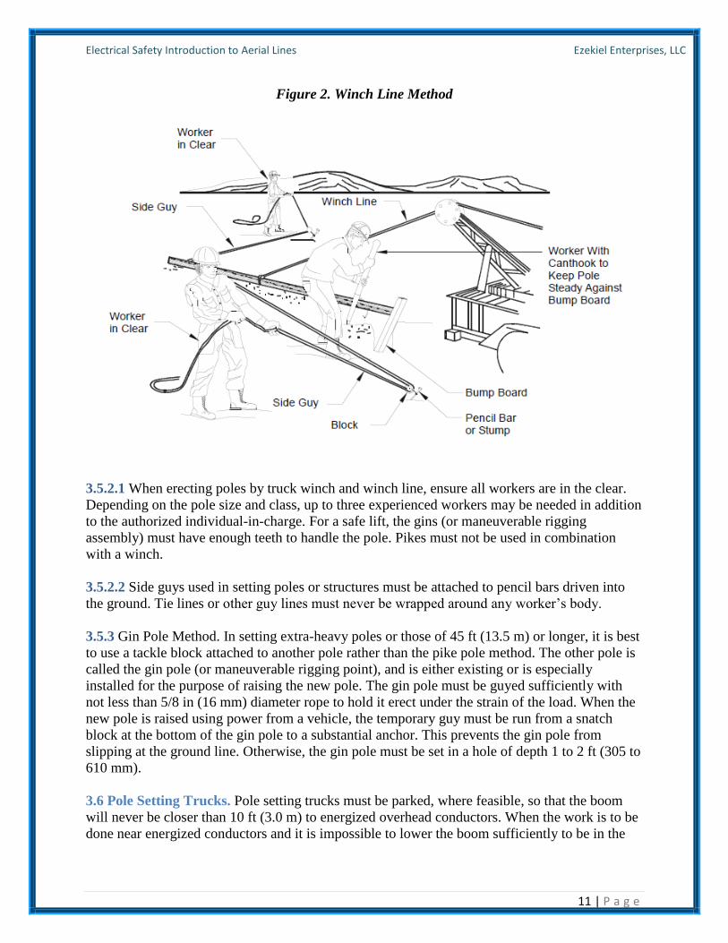
3.5.2 Winch Line Method. Figure 2 illustrates the winch line method.
Electrical Safety Introduction to Aerial Lines Ezekiel Enterprises, LLC
11 | P a g e
Figure 2. Winch Line Method
3.5.2.1 When erecting poles by truck winch and winch line, ensure all workers are in the clear.
Depending on the pole size and class, up to three experienced workers may be needed in addition
to the authorized individual-in-charge. For a safe lift, the gins (or maneuverable rigging
assembly) must have enough teeth to handle the pole. Pikes must not be used in combination
with a winch.
3.5.2.2 Side guys used in setting poles or structures must be attached to pencil bars driven into
the ground. Tie lines or other guy lines must never be wrapped around any worker’s body.
3.5.3 Gin Pole Method. In setting extra-heavy poles or those of 45 ft (13.5 m) or longer, it is best
to use a tackle block attached to another pole rather than the pike pole method. The other pole is
called the gin pole (or maneuverable rigging point), and is either existing or is especially
installed for the purpose of raising the new pole. The gin pole must be guyed sufficiently with
not less than 5/8 in (16 mm) diameter rope to hold it erect under the strain of the load. When the
new pole is raised using power from a vehicle, the temporary guy must be run from a snatch
block at the bottom of the gin pole to a substantial anchor. This prevents the gin pole from
slipping at the ground line. Otherwise, the gin pole must be set in a hole of depth 1 to 2 ft (305 to
610 mm).
3.6 Pole Setting Trucks. Pole setting trucks must be parked, where feasible, so that the boom
will never be closer than 10 ft (3.0 m) to energized overhead conductors. When the work is to be
done near energized conductors and it is impossible to lower the boom sufficiently to be in the
Electrical Safety Introduction to Aerial Lines Ezekiel Enterprises, LLC
12 | P a g e
clear, the conductors must be placed in an electrically safe work condition before work is begun.
When it is not possible to deenergize the conductors, and work must be done with the boom
close to energized conductors, all personnel must keep away from the frame of the truck and
must not touch the pole. Pole guards or insulated blankets must be used. Never touch with bare
hands a pole that is being set in an energized line. Instead, an insulated cant hook or dry rope
around the butt of the pole may be used to guide it into the hole.
3.7 Setting Poles in Energized Lines. Only an electrical worker qualified as a Journeyman or
Craftsman must be permitted to guide poles through energized conductors. This operation is
classified as “energized work” and appropriate permits and/or authorizations must be obtained.
Employees must wear appropriately rated arc flash personal protective equipment as outlined in
Table 4-1.
3.7.1 When a pole of any type is being set or removed between or near conductors energized at
more than 600 V, the pole, winch cable, and truck frame must be effectively grounded with
protective grounds. Lines must be covered with rubber protective equipment to prevent poles
from touching energized parts, and workers must use rubber gloves. Attach a protective ground
to the frame of all winches. If the pole is to be erected by hand (pikes), the protective ground
must be attached to the pole (using an approved grounding band) approximately 15 ft (4.5 m)
from the butt end. Installing and use pole guards. In all cases, exercise extreme care to keep the
pole from contacting conductors.
3.7.2 Wood poles must not be considered as providing adequate insulation from energized lines.
3.8 Backfilling the Hole. Backfill the hole after the pole has been placed. Use pikes to align the
pole while backfilling. Pikes must not be removed until sufficient tamping has been done to
prevent the pole from falling.
3.9 Dismantling Poles. Pole dismantling from a live line is a particularly hazardous operation.
Exercise extraordinary care.
3.9.1 Each pole must be restrained in at least three different directions by ropes before any work
proceeds on the pole. This may be done by the following procedure:
3.9.1.1 Make two turns around the pole with a sling and tie securely.
3.9.1.2 Tie three lines around the sling at the proper angles.
3.9.1.3 Insert pike poles under two sides of the sling well up the pole.
3.9.1.4 Snub off securely by pencil bars driven into solid ground or by any other substantial
snub.
3.9.2 Always check the pole to see if additional support may be necessary because of pole
conditions or strains.

Electrical Safety Introduction to Aerial Lines Ezekiel Enterprises, LLC
13 | P a g e
3.9.2.1 Determine the condition of the pole butt before removing guys or wires, and support the
pole with additional pike poles or temporary guys if necessary.
3.9.2.2 When an old or reinforced pole is to be dismantled, guy it sufficiently to withstand any
altered strain on it. Be sure to include the weight of personnel who are to work on the pole while
dismantling.
3.9.2.3 When changing the strain on a pole, the authorized individual-in-charge must ensure it is
sufficiently guyed to stand the altered strain and prevent the pole from falling. Workers must not
climb a pole that is under an abnormal strain.
3.9.2.4 A truck equipped with an “A” frame and backed up to the pole can be used to restrain the
pole. The top of the “A” frame can be tied by the winch line to the pole. The pole at the ground
line level can be securely tied off to the truck.
3.10 In locations where poles cannot be lowered with a rope or derrick, a guideline must be
attached so that the pole moves in the desired direction.
3.11 All members of a crew who are not actively engaged in pole removal must stand well clear
in case the pole must fall. Where appropriate, stop all pedestrians and traffic during pole
removal.
3.12 When a pole is being removed, dismantle the pole before beginning the excavation around
the butt.
4 Climbing and Working on Poles.
Workers must be familiar with the general rules for climbing poles and approaching the overhead
work area, the differences of climbing wood poles as opposed to steel towers, and the dangers
inherent in crossing overhead structures from one side to another.
4.1 General Rules.
4.1.1 Do not work at the base of a structure or a pole while others are working above.
4.1.2 Before climbing a pole the worker must first determine:
• What circuits are energized and their voltage, and any unusual conditions which might
pose a hazard.
• The types and locations of circuits, and the direction of feeds.
• The best climbing space to avoid all live wires, grounded wires, and signal circuits.
4.1.3 Ensure there is an ample supply of rubber protective equipment on hand to completely
protect the worker on the pole from all live wires, grounded wires, and signal circuits.
4.1.4 Only one worker is permitted to ascend or descend a pole at any one time. Other workers
must be in place on the pole or on the ground before the worker ascends or descends the pole.

Electrical Safety Introduction to Aerial Lines Ezekiel Enterprises, LLC
14 | P a g e
4.1.5 Extraordinary care is required of the workers when it becomes necessary for one worker to
work above the other.
4.1.6 Before climbing poles, ladders, scaffolds, or other elevated structures; riding span wires,
messengers or cables; or entering cable cars, boatswain chairs or similar equipment; each worker
must first ensure the structure or device is strong enough to sustain the worker’s weight.
4.2 Pole Inspection Before Climbing. The type of pole to be climbed affects the precautions
that the worker must take in regards to climbing equipment and procedures. All types of poles
must be safe to climb in terms of being strong enough to bear the weight of the climbers and
their tools, and in having adequate climbing space. Before allowing anyone to climb on a pole,
the authorized individual-in-charge must ensure the pole is inspected, i.e. hammer tested and
pike pole rocking test, and that it can be safely climbed based on the following:
4.2.1 Determine age, physical condition, and treatment of the pole. Do not climb a pole unless
you are sure it can safely hold your weight. Before climbing, inspect the pole for the following:
• General condition – buckling at the ground line or an unusual angle may indicate pole
has rotted or is broken.
• Cracks – horizontal cracks perpendicular to the grain of the pole may weaken pole.
Vertical ones can pose a hazard to the climber and employees should keep their gaffs
away from them while climbing.
• Holes – hollow spots or woodpecker holes can reduce the strength of a wood pole.
• Rotting and decay – are cutout hazards and are possible indication of the age and
internal condition of the pole.
• Knots – one large knot or several smaller ones at the same height may be evidence of a
weak point on the pole.
• Depth of setting – evidence of the existence of a former ground line substantially above
the existing ground line may be an indication the pole is not longer buried to a sufficient
extent.
• Soil conditions – soft, wet or loose soil may not support any changes of stress on the
pole.
• Burn marks – burning from transformer failures or conductor faults could damage the
pole.
4.2.2 Wood poles shall be inspected and tested by the qualified employee prior to any climbing
activities using one of the following methods:
• Hammer Test – rap the pole sharply with a hammer weighing about 3 lb (1.4 kg),
starting near the ground line and continuing upwards circumferentially around the pole to
a height of approximately 6 ft (2 m). The hammer will produce a clear sound and rebound
sharply when striking sound wood. Decay pockets will be indicated by a dull sound or a
less pronounced hammer rebound. Also, prod the pole as near the ground line as possible
using a pole prod or a screwdriver with a blade at least 5 in (127 mm) long. If substantial
decay is encountered, the pole is considered unsafe.
• Rocking Test – apply a horizontal force to the pole and attempt to rock it back and forth
in a direction perpendicular to the line. Caution must be exercised to avoid causing power

Electrical Safety Introduction to Aerial Lines Ezekiel Enterprises, LLC
15 | P a g e
lines to swing together. The force may be applied either by pushing with a pike pole or
pulling with a rope. If the pole cracks during the test, it shall be considered unsafe.
4.2.3 Determine if the configuration of conductors and equipment on the pole will provide
adequate climbing space.
4.2.4 Determine if the removal of supporting conductors or guys may affect the safety of
workers.
4.2.5 Determine if the poles to be climbed can be supported in such a way as to safely support
workers on the poles. Pikes are not acceptable as a support method while personnel are working
on poles.
5 Pole Climbing Equipment.
5.1 General Rules.
5.1.1 Make sure each worker who is authorized to climb has a full set of climbing equipment.
Never loan or borrow a set of climbing equipment.
5.1.2 Carefully inspect climbing equipment before each day’s climbing activities. Examine
leather for cuts, cracks, and enlarged buckle tongue holes. Examine metal parts for cracks, wear,
or loose attachments. Examine climbers (gaffs) for proper cutting edges, length, and shape.
5.1.3 The authorized individual-in-charge, or a designated worker, must inspect all tools, safety
devices, and other equipment in use on a weekly basis. Any item that is not considered safe must
be condemned, regardless of ownership, and must not be used.
5.1.4 Ensure that employees understand that fabricated or purchased fall protection must meet or
exceed the requirements outlined in ANSI Z359, Safety Requirements for Personal Fall Arrest
Systems, Subsystems, and Components, and with ASTM F887.04, Standard Specifications for
Personal Climbing Equipment. \2\ Body harnesses, meeting the requirements of ANSI Z359,
with straps or lanyards, must be worn to protect personnel working at elevated locations on
bucket trucks, power poles, towers, platforms, and other structures. /2/ Inspect body harnesses
and straps before use each day to determine they are in safe working condition.
5.1.5 Use body harnesses instead of body belts for fall protection.
5.2 Wooden Pole Climbing Equipment. Equipment sets each consist of a body belt (or body
harness), a pole strap, and climbers (an assembly of gaffs, leg straps, and pads). The Edison
Electric Institute provides an excellent document entitled “Use and Care of Pole Climbing
Equipment” which is appropriate for use in training for pole climbing certification.
5.2.1 Climbers must meet the following requirements:
• Leg iron (shank) to be made of spring steel.
• Gaff (spur) to be forged from tool steel.

Electrical Safety Introduction to Aerial Lines Ezekiel Enterprises, LLC
16 | P a g e
• Leg iron length must be in the range from 15 to 18 in (381 to 457 mm) from the instep
to end of the shank.
• Leather straps must be at least 1-1/4 in (32 mm) wide and 22 in (559 mm) long.
• Pads must adequately protect the calves.
5.2.2 Climbers, pole straps, and other leather items that have any of the following defects must
not be used until repaired:
• Cracked, dry, or rotten leather.
• Leather which is worn thin.
• Cuts or worn places which are of sufficient depth to weaken the leather.
• Broken stitches or loose rivets at buckles, D-rings, or snaps.
• Snaps which have weak springs behind the tongue or loose rivets which hold the
tongue.
• Loose tongues in buckles.
• Buckles, D-rings, or snaps that show considerable wear or which have been cracked or
bent.
5.2.3 Leather equipment in regular use must be cleaned and dressed at least every three months,
and more frequently when the equipment is wet from rain or perspiration, or is soiled with dirt or
mud. Leather equipment not in regular use must be cleaned and dressed at least every six
months.
5.2.3.1 Wipe off all surface dirt and mud with a sponge dampened (not wet) with water. Never
use gasoline or other cleaning fluids, as they tend to dry out and harden the leather.
5.2.3.2 Wash leather with a clean sponge in clear lukewarm water and a neutral soap (free from
alkali), preferably Saddle soap. Thoroughly wash the entire length of the leather and work the
lather well into all parts. Place in a cool area to dry.
5.2.3.3 Leather must be dressed with oil after each cleaning. Use a small quantity (about 20
milliliters (4 teaspoons)) of pure neatsfoot oil per set of equipment and apply it gradually with
the hands, using long light strokes while the leather is still damp from washing. Leave in a cool
place to dry for about 24 hours, and then rub the leather vigorously with a soft cloth to remove
all excess oil.
5.2.3.4 When safety harnesses/belts and straps are not in use, they must be stored in designated
compartments on the service truck or other suitable location to protect them from damage. When
stored, climbers must be wrapped in pairs and fastened with their straps.
5.2.4 Keep climbers, straps, and pads in good conditions at all times. Inspect climbers before
each use to detect nicked or dulled cutting edges on the gaff. Check them as soon as possible
after striking them against hard objects such as pole hardware or nails. The worker must inspect
climbers in regular use at least weekly. If any of the following conditions are found, repair or
replace the climbers before using:
• Loose gaff.
• Nicks and depressions in the gaff.

Electrical Safety Introduction to Aerial Lines Ezekiel Enterprises, LLC
17 | P a g e
• Ridge of gaff not in alignment.
• Dull gaffs.
• Broken or distorted gaff points.
• Broken, loose leg or foot strap loop.
• Excessively worn, cracked, or torn straps and pads.
• Enlarged buckle holes in the straps.
• Broken or damaged strap buckles.
• Fractured or cracked leg irons and stirrups.
• Excessively worn stirrups.
• Fractured leg iron sleeves.
• Broken or loose rivets or screws on sleeves and straps.
• Defective strap rings.
• Broken or damaged loop clip-on straps.
• Gaff guards not in good condition.
• Improper length of gaffs.
5.2.5 Gaffs must be at least 1-1/4 in (32 mm) long, measured from the point of the gaff to the
point of contact with the stirrup on the under side.
5.2.6 Sharpen climbers using a gaff-shaping bit as follows:
5.2.6.1 Place the climber between wood in a vise with the leg iron horizontal and the gaff on the
topside.
5.2.6.2 Use a smooth cut file and finish with a sharpening stone. Never grind with an emery
wheel, as this takes the temper out of the metal.
5.2.6.3 The outer ridge of the gaff must never be filed. To obtain the proper width, a file may be
used on the rounded portion. Apply strokes that follow the contour of the gaff.
5.2.6.4 To sharpen the gaff to proper thickness, file the metal from the flat inner side of the gaff.
Care must be taken to prevent notching the leg irons or stirrup. Use forward motions toward the
point and down to edges of the underside of the gaff. Do not allow rocking motions of the file
because this can round the edges of the gaff. After the proper thickness has been reached, the
underside of the gaff must be straight to within 1/16 in (1.6 mm) of the point, then rounded
slightly toward the ridge of the gaff on a radius of 1/4 in (6.4 mm). Additional sharpness may be
obtained following filing by dressing the underside and rounded portion of the tip with the
honing stone. Burrs along the edges must also be removed with the stone.
5.2.6.5 Never use a climber with a gaff shorter than 1-1/4 in (32 mm), as measured on the flat
side.
5.2.7 Restore damaged or dull gaffs to original shape (see Figure 3) by filing and honing (see
Figure 4). If gaffs cannot be restored, replace them.

Electrical Safety Introduction to Aerial Lines Ezekiel Enterprises, LLC
18 | P a g e
Figure 3. Comparison of Correct and Incorrect Gaff Shapes
Figure 4. Honing a Gaff

Electrical Safety Introduction to Aerial Lines Ezekiel Enterprises, LLC
19 | P a g e
5.2.8 Three methods are normally used to determine if gaffs are properly sharpened.
5.2.8.1 Gaging Method. The gaging method is used to determine the length, width, and thickness
of the gaff and profile of the point. Reference lines are scored on the gage with slots provided to
determine if the gaff length is satisfactory. Most gages also provide a contour test to determine if
the point is properly curved. Openings are provided for determining if the point is too keen. Each
manufacturer makes a gaff gage to be used with its own climbers. Thus, gaff gages are not
usually interchangeable. Manufacturer’s instructions must always be used if available. The
“thickness” slot in the gage is used to measure the thickness of the gaff at 1/2 in (12.7 mm) from
the point. These measurements are made with the outer ridge of the gaff resting flat against the
part of the gage containing the scored lines. If the point of the gaff extends beyond the farthest
line, the gaff is too thin. If it does not reach the nearest line, then it is too thick. The “width” slot
on the gage is used to measure the width 1/2 to 1 in (12.7 to 25.4 mm) from the point. The same
methods and reference line are used in measuring for thickness. A minimum length reference
line is provided, intersecting the thickness measurements, to determine if the gaff meets
minimum lengths.
5.2.8.2 Plane Test Method. The plane test method may be used with the gage, or independently if
the gaffs are sharpened by machine process. The test is made by using a soft board to determine
if proper sharpness has been reached. Place the climber with the gaff side down and parallel to
the board without applying downward pressure above the gaff. Push the climber along the board.
If the gaff is properly contoured and sharpened, it can dig into the wood and hold within
approximately 1 in (25.4 mm). If the climber continues to glide along the board for more than 1
in (25.4 mm), additional honing is required. After the “plane test” has been made, it can be
supplemented by applying a cutout test. Jab the gaff into the board at about a 30-degree angle for
approximately 1/4 in (6 mm). Bring the leg iron down against the wood while applying forward
pressure--one hand holds the leg iron and the other holds the stirrup. If the gaff cuts out within 3
in (76 mm), it is improperly sharpened.
5.2.8.3 Pole Cutout Method. The pole cutout method is used after climbers have been machine
sharpened or gauged (and as often as required thereafter). Perform a pole cutout test in
accordance with Table 2 before climbing. Check failed gaffs with a gaff gauge to determine the
reason for failure and correct the deficiency.

Electrical Safety Introduction to Aerial Lines Ezekiel Enterprises, LLC
20 | P a g e
Table 2. In-Use Check of Pole Climber Gaffs
5.2.9 To protect the gaffs, use gaff guards when climbers are not being used. They must also be
used when other tools and materials are stored or transported along with the climbers.
Note: Climbers must never be stored or transported without appropriate gaff guards.
5.2.10 Do not wear climbers when:
• Working on the ground.
• Traveling to and from a job.
• Piking poles
• Walking through underbrush or rough terrain
• Riding in motor vehicles.
5.3 Concrete and Steel Pole Climbing.
5.3.1 OSHA standards (29 CFR 1910 and 1926) require fall protection for certain working
heights. Acceptable fall protection includes the use of standard railings and toeboards, floor
opening covers, or a personal fall arrest system. A body belt is no longer acceptable as part of a
personal fall arrest system.
5.3.1.1 Fall protection is required for operations and maintenance activities when personnel are
required to work at a height of 4 ft (1.2 m) or more above ground or the next lower level. For
construction activities workers must be protected from falls when working at a height of 6 ft (1.8
m) or more. An approved positioning device that limits a fall to less than 2 ft (0.6 m) must be
used when a worker needs to be supported on an elevated vertical surface such as a wall or utility
pole, and work with both hands free while leaning.

Electrical Safety Introduction to Aerial Lines Ezekiel Enterprises, LLC
21 | P a g e
5.3.1.2 A proper anchor point must be identified and evaluated by qualified personnel before an
appropriate system can be selected. OSHA regulations accept pad eyes, bolt holes, and other
sturdy structures capable of supporting 5,000 lb (2,200 kg) per attached worker.
5.3.1.3 Positive systems have an anchor point independent of the support method, a harness to
hold the worker, and a connecting device between the anchor point and the harness.
5.3.1.4 Harnesses must only be used for the personal protective purpose for which they are
designed. In addition to fall-arrest harnesses, there are fall-arrest/positioning, fall-
arrest/suspension, fall-arrest/retrieval, and retrieval/positioning harnesses.
5.3.1.5 Manufacturer’s instructions in regard to height and weight must be followed for sizing of
the harnesses and their connecting devices, and for inspection and maintenance of the complete
systems. All equipment must be taken out of service and inspected for damage after being
subjected to a fall impact.
5.3.2 Workers authorized to climb must have a complete set of approved tools. The number of
tools carried in tool belts must be kept to a minimum. Tools must not be carried in safety
harnesses.
6 Pole Climbing and Work Precautions.
Only after a determination of the pole’s safety, the collection of necessary climbing equipment
and work tools, and obtaining assurance that the line is placed in an electrically safe work
condition, or that energized work is authorized to be carried out, can the worker start climbing.
Protect hands and arms by wearing gloves and long sleeve shirts. Refer to paragraph 4.2 for pole
inspection requirements before climbing.
6.1 General Pole Climbing Precautions.
6.1.1 Arrange tools and equipment to allow both hands to be free for climbing.
6.1.2 Do not stand on mailboxes, signs, fire alarm boxes, or similar equipment that may be
attached to the pole or located near it.
6.1.3 Do not race up and coast down poles.
6.1.4 Do not use safety straps while climbing, except when climbing over slippery or ice-coated
crossarms or timbers. Whenever the hands are apt to slip off, a safety strap must be used. The use
of rope safeties is prohibited.
6.1.5 Remove all signs from a pole before any worker climbs or does any work above them on a
pole. It is not desirable to have signs on poles, but some signs, such as street signs, may be
necessary. If street signs are removed, they must be replaced as soon as possible after work is
completed.

Electrical Safety Introduction to Aerial Lines Ezekiel Enterprises, LLC
22 | P a g e
6.1.6 Climb on the high side of a raked or leaning pole, if possible, but do not climb on the side
where the ground wire is attached. Avoid grasping pins, brackets, crossarms, braces, or other
attachments that might pull lose and cause a fall.
6.1.7 Never slide down any type of pole or any guy wire. If it is impossible to use climbers for
ascending and descending such places, ladders or other means must be used.
6.1.8 Do not ride overhead guys or cables. (This is not intended to apply to cables installed for
river crossings or otherwise designed to support workers in suitable conveyances.)
6.1.9 If more than one worker needs to work on the pole at the same time, the first worker must
reach working position before the next worker leaves the ground. Ordinarily, no worker must
work directly under another worker on the same pole. When this is necessary, take extreme care
to prevent tools or other objects from being dropped on the worker below.
6.1.10 Minimize the number of tools carried in tool belts. Keep all other tools on the ground until
they are required. Needed tools must be raised and lowered by means of a canvas bucket
attached to a handline.
6.1.11 When carrying a handline up a pole, leave the handline uncoiled with one end attached to
the rear of the body belt or harness. When climbing with a handline, take care to prevent the
handline from fouling on any pole attachments.
6.1.12 Wear appropriately rated arc flash personal protective equipment as specified in Table 4-
1.
6.1.13 Discontinue work during adverse weather conditions such as thunderstorms, rain, high
winds, and icy conditions. In bad weather, do not climb poles except for emergency restoration
work.
6.2 Wooden Pole Climbing Precautions.
6.2.1 Seat gaffs securely. Be especially vigilant when the pole is ice or sleet covered.
6.2.2 Use pole steps whenever they are available, but only after checking that they can be used
safely.
6.2.3 Use climbers carefully on the pole to avoid injury to another worker on the pole.
6.2.4 Be careful to avoid weather cracks, checks, knots, shakes, rots, and hard places, which
might cause gaffs to cut out. Remove any tacks or nails which may impede safe climbing.
6.3 Concrete and Steel Pole and Tower Climbing Precautions.

Electrical Safety Introduction to Aerial Lines Ezekiel Enterprises, LLC
23 | P a g e
6.3.1 Always make sure that gloves and shoe soles are in good condition and free from grease or
other lubricants. Many falls are caused by slick work gloves or slick shoes. Rough cord sole shoe
or boots are recommended. Be particularly careful in wet or icy weather conditions.
6.3.2 Carefully wear and regularly inspect the safety harness since steel and concrete surfaces
can easily damage or cut the harness.
6.4 Working on Poles. Never change the amount of strain on a pole by adding or removing
wires until you are sure that the pole can stand the altered strain. If in doubt, consult your
authorized individual in charge.
6.5 Safety Straps. Wear safety straps at all times when handling wires or apparatus while on a
pole or structure. The following precautions must be taken:
6.5.1 Be careful in attaching snaps to D-rings. Visually ensure that the snap keeper is fully closed
in the correct ring before any weight is applied to the safety strap.
6.5.2 Always be sure that safety straps are connected and not twisted while in use.
6.5.3 Never depend on a crossarm or crossarm pins and braces for support.
6.5.4 Never attach safety straps above the crossarm in the top gain or around insulator pins,
crossarm braces, transformer hangers, pole steps, or guy wires. If there is no crossarm in the top
gain, the strap must not be placed closer than 2 ft (0.6 m) to the top of the pole. In this case take
precautions to assure that the strap does not slip off. Ideally the strap must be below the top pole
attachment, except where that attachment is above eye level.
6.5.5 Never fasten both safety harness snaps in the same D-ring in order to reach out farther on
the pole. An extension safety strap must be used or the safety harness let out so that work can be
performed with the safety harness snaps fastened one in each D-ring.
6.5.6 Do not attach metal hooks or other metal devices to body harnesses. Metal chains and
keepers must not be used. Instead, use leather straps or rawhide thongs with hard wood or fiber
keepers. Care must be taken to prevent the snaps on the safety harnesses/belts from coming in
contact with anything that may open a snap. The tongue of the snap on the safety harness/belt
must face away from the body.
6.6 Hoisting or Lowering Materials. Take the following precautions when hoisting or lowering
materials:
6.6.1 Drop material that cannot be lowered safely only if there is no danger to workers or the
public.
6.6.2 Position workers engaged in hoisting tools and materials so that they can not be injured by
a falling item.

Electrical Safety Introduction to Aerial Lines Ezekiel Enterprises, LLC
24 | P a g e
6.6.3 Do not leave materials and tools overhead in an insecure position. Large objects must be
securely lashed.
7 Crossing Structures.
7.1 To get from one side of a double-pole supported structure to the other, the worker must
descend to the ground and go up the other pole unless there are adequate handholds and adequate
clearances from live parts to allow safe crossing along the structure.
7.2 When it is necessary to climb half-way across a crossarm to inspect middle phase insulators,
the worker may climb the rest of the way across, provided that, a safety harness/belt can be kept
strapped around a timber as a safeguard.
7.3 Never cross through an open-air switch unless both sides are placed in an electrically safe
work condition.
7.4 Do not use air switch arcing horns for support in walking timbers since these horns break
easily and a fall could result.
7.5 Never walk along an H-frame cross-arm with the line energized.
8 Stringing Or Removing De-energized Conductors And Overhead Ground Wires.
8.1 Pre-Work Meeting. Discuss the plan of operation, type of equipment to be used, adjacent
energized lines, necessary grounding devices and procedures, crossover methods, and Safe
Clearance requirements before stringing or removing de-energized conductors or overhead
ground wires.
8.2 Work Adjacent to Energized Lines.
Note: Work adjacent to energized lines is not authorized.
8.2.1 The worker attending the payout reel must wear rubber gloves when pulling wire over or
near energized conductors, and be positioned on an insulated stand of a size equivalent to or
larger than a standard rubber blanket.
8.2.2 Ground the payout reel. The authorized individual-in-charge must approve any deviation in
grounding the payout reels.
8.2.3 A bull line, which must be of dry polypropylene rope not smaller than 1/2 in (12.7 mm)
diameter, must be placed in position to pull the wire before attempting to string it. The bull line
must be of sufficient length to reach the distance the wire is to be pulled. Fasten the wire to the
end of the bull line and pull it into position.

Electrical Safety Introduction to Aerial Lines Ezekiel Enterprises, LLC
25 | P a g e
8.2.4 A vehicle used to pull the wire must be positioned so that the driver can see the signals of
the reel operator. Both in pulling in the wire and in sagging it, the pulling must be slow and
steady to prevent swinging the wires into the energized conductors. The wire must be watched
carefully to prevent its hanging up on tree limbs, weeds, and other obstructions.
8.2.5 Do not touch any conductors or wires on the ground without rubber gloves.
8.2.6 Wear rubber gloves and use other protective devices, as appropriate when wires are strung
and sagged over, under, or across conductors carrying a voltage of 5,000 V or less. Positively
and constantly ground conductors carrying more than 5,000 V during the stringing operation.
Ground the wire with standard grounding devices as soon as it is ready to be dead-ended.
8.2.7 Discontinue operations and seek appropriate shelter when notified that a lightning warning
is in effect. Electrical charges can appear on the line from a lightning strike or from induced
static charges from a very dry atmosphere. Be in contact with the Base Weather Service and
cease outside activities when notified of a lightning warning. Waiting for an indication of
lightning can expose a work crew to adverse weather conditions.
8.2.8 Keep wires being strung along or across streets or highways higher than any expected car
or truck traffic. Traffic must be blocked when this line elevation is not possible.
8.3 Grounding. Requirements for grounding of de-energized lines are covered in Chapter 7.
Other grounding requirements are as follows:
8.3.1 Permanent ground wires are installed to protect workers. All permanent grounds must be
installed in accordance with the requirements of the NEC or the NESC, as applicable. If the
permanent grounds are not installed, the metallic case, covering, or mounting support of any
energized piece of electrical equipment must be treated as if it is energized at full voltage.
8.3.2 Install ground wires clear of all metallic line equipment (except that which is normally
grounded), hardware, and street lighting fixtures.
8.3.3 Install ground wires on distribution wood poles with protective molding for the entire
working length of the pole to protect them from damage. The entire working length of the pole is
the distance from the point where ground wire terminates near the top of the pole to 5 ft (1.5 m)
below the lowest crossarm or bracket, and from the ground line to 8 ft (2.5 m) above the ground
line.
8.3.4 Never cut an overhead ground wire or neutral wires without the specific approval of the
authorized individual-in-charge. Always avoid opening a joint in such a wire without first
bridging the joint with wire of equal or larger size.
8.4 Handling and Stringing. ANSI/IEEE 524 provide general recommendations on the
methods, equipment, and tools used for the stringing of overhead line conductors and ground
wires. Safety precautions include:

Electrical Safety Introduction to Aerial Lines Ezekiel Enterprises, LLC
26 | P a g e
8.4.1 Reels. Use adequate braking to stop all payout reels. Do not touch or attempt to hand stop a
revolving reel.
8.4.2 Conductors. Securely fasten the inside end of the coil wire to the reel to prevent the wire
from getting loose when the wire has been extended out. If the inside end of the coil cannot be
secured, a tail rope must be fastened securely to the wire before the end is reached to prevent its
getting loose.
8.4.3 Grounding. Bond and ground all stringing equipment, such as reel stands, trailers, pullers,
or tensioners.
8.5 Primary Line Installation. String the lines to clear the ground by an amount not less than
that specified in the NESC. These minimums depend upon whether the line is above a street
(consider its traffic classification), above a pedestrian way, or over or near other structures. Wire
and guys that are being strung must be kept clear of any possible interference with public traffic
of any type. Where it is necessary to block traffic temporarily while wires and guys are being
installed, one or more members of the crew must be assigned to direct traffic.
8.5.1 Stringing Wire. Stringing by activity personnel must normally be done by the tension
method, since this keeps the conductor clear of energized conductors and clear of obstacles that
might cause surface damage to the wire. Slack stringing may be appropriate for new short line
extensions. Sag the lines to meet the requirements of the NESC.
8.5.1.1 Take care not to put kinks into any part of the line when stringing wires. Kinks reduce the
strength of the wire and may result in fallen wires later.
8.5.1.2 Before changing the strains on a pole by adding wires, an engineering evaluation must be
completed to ensure that the pole can safely stand the new strain.
8.5.2 Clipping-In or Tying Wires. This involves the transferring of sagged conductors from their
stringing travelers to their permanent insulator positions where they may either be clamped or
tied to insulators.
8.5.2.1 Securely tie wires at each tie-in-type insulator to prevent the wires becoming loose and
falling to the ground. Where double arms are provided, line wires must be well tied-in to
insulators on each arm. This applies to both pin- and post-type tie-top insulator work. Clamp-
type insulators must have the clamps tightened as specified by the manufacturer.
8.5.2.2 Test the phase wires with a potential transformer or other means, to make sure that the
phase wires of one circuit are being connected to the corresponding phase wires of the other
circuit when it is necessary to connect circuits at any point on the line.
8.5.2.3 Be sure that the phase wires are not crossed when turning the vertical angle on three-
phase lines; that is, phase wires must take the same position leaving an angle as coming into it.

Electrical Safety Introduction to Aerial Lines Ezekiel Enterprises, LLC
27 | P a g e
8.6 Secondary Line Installation. Install secondary lines to meet line clearance requirements of
the NESC. Lines can be single or triplex wires. Workers must be particularly careful in stringing
secondary services to avoid the hazards of working in close proximity to primary lines.
8.6.1 De-energize and ground nearby or adjacent energized lines before stringing secondary
wires.
8.6.2 Take care not to injure the weatherproof covering when handling and stringing of
weatherproof-covered wires.
8.7 Removing Lines. Use the same general precautions as stringing wires when removing or
salvaging wires. Where practical, the wire to be removed must be pulled out and laid flat on the
ground before any attempt is made to coil the wire by hand or on a non-power-driven reel.
8.7.1 Never change the strains on a pole by removing wires until certain that the pole can safely
stand the altered strain. Where a pole will be weakened by the removal of the wires, it must be
guyed before these wires are removed. All wires must be lowered with a handline. Use care
before cutting a wire aloft to avoid contact with other wires.
8.7.2 Do not allow lines which are being cut or rearranged to sag on, or be blown against other
electric power lines, signal lines, signal equipment, metal sheaths of cables, metal pipes, ground
wires, metal fixtures on poles, guy wires, or span wires.
8.7.3 Do not allow wires which have been cut, or which are being arranged, to fall near or on a
roadway where they might endanger traffic. Notify all persons working on lower levels of poles
and all personnel on the ground well in advance of the cutting so that they may stand clear.
8.8 Guying. No installation or removal of guys must ever be attempted without engineering
guidance.
8.8.1 Installation. Install guys to meet the following requirements:
8.8.1.1 When insulators are used they must be connected into the guy wire line before the guy
wire is set in place. In new work, guys must generally be installed before line wires are strung. In
reconstruction work, guys must be installed before any changes are made in the line wires and
care must be taken not to place excessive pull on the pole and wires already in position.
8.8.1.2 Install guys so that there is minimal interference with the climbing space, and to clear all
energized wires.
8.8.1.3 Provide guy strain insulators to obtain necessary insulation when required by building or
safety codes.
8.8.1.4 Install guys to the correct tension. Where necessary, a guy hook may be used to prevent
the guy from slipping down the pole. Locate these hooks so they do not interfere with climbing,
and place them so they are not convenient for use as a step. Where guys are liable to cut into the

Electrical Safety Introduction to Aerial Lines Ezekiel Enterprises, LLC
28 | P a g e
surface of a pole, the pole must be protected by a guy plate at the point where the guy is attached.
The plate must be well secured to the pole to prevent the possibility of injury to a worker
climbing up or down the pole.
8.8.1.5 Install guys so that they do not interfere with street or highway traffic. Equip guys located
near streets, or highways, with traffic guards. Traffic guards are sometimes called “anchor
shields”. Guy guards (traffic shields or anchor shields) must be yellow.
8.8.1.6 Install guy wires so that they do not rub against messenger or signal cables.
8.8.1.7 Do not use guy wire containing snarls or kinks for line work. Use guy wires of the correct
length to avoid splices.
8.8.2 Removal of Guys. Determine the condition of the pole before removing guys. Brace the
pole securely if it is weak before any changes in pole strains are made.
8.8.2.1 Brace the pole temporarily if the removal of guys from a pole can change the strain and
present a dangerous condition.
8.8.2.2 Where it is not possible to install side guys, poles may need to be braced to be self-
supporting. Install pole bracing so that it does not interfere with climbing or with street or
highway traffic. Pole braced guys must not be used on poles which must be climbed.
8.9 Insulators. Pick up insulators by their tops to avoid cutting gloves or hands on the insulator
petticoats. Do not screw down insulators too tightly because their tops might break off, cutting
gloves or hands.
9 Energized Work. Energized work requirements are provided in Chapter 8.
10 Street Lighting.
10.1 Voltage Level. Street lighting circuits might be either low-voltage multiple circuits or high-
voltage series circuits. It is important that the type of circuit be identified \2\ and placed in an
electrically safe work condition before starting work because of the different voltage levels
involved. /2/ Workers must wear PPE in accordance with Chapter 4when working on street
lighting circuits.
10.2 Clearance Requirements. Street lighting lines, fixtures, and wires must be considered
energized, which requires wearing personnel protective equipment, unless a Safe Clearance
permit is obtained and the line grounded. The voltage of street lighting circuit must be treated as
that of the highest voltage occupying any of the poles on which the street lighting circuit is run.
10.3 Multiple Street Lighting Circuits. Multiple street lighting circuits must be treated with the
same precautions as the circuits to which they are connected, unless the circuit is located on a
structure with a higher voltage wire, in which case it must be considered to be at the higher
voltage level.

Electrical Safety Introduction to Aerial Lines Ezekiel Enterprises, LLC
29 | P a g e
10.4 Series Street Lighting Circuits. Before a series street lighting circuit is opened and work is
performed, the following procedures must be followed:
10.4.1 Disconnect the circuit from the source of supply by opening disconnecting switches or
other cutouts in accordance with a Safe Clearance permit and lockout-tagout equipment. Do not
depend on time switches or other automatic devices.
10.4.2 Jumper the circuit to avoid an open-circuit condition.
10.4.3 In replacing street light bulbs and lamp globes in street lighting brackets, there is danger
of an arc developing and causing serious damage and injury if the spring clips in the receptacle
do not make contact. These springs might have been heated to the extent that they have lost their
temper, or for some other reason, do not close the circuit when the lamp socket is pulled out. Use
approved changers with at least 6 ft (1.8 m) handles for replacing lamps on series street lighting
circuits. Workers must wear PPE in accordance with Chapter 4 when removing or installing
lamps where lamp changers cannot be used.
10.5 Climbing Space. Maintain safe access by hanging street lighting fixtures clear of the
climbing space. All bolts, lag screws, and other hardware used in securing the fixtures must be
cut, filed, or coated to eliminated sharp or protruding edges or points.
10.6 Time Switches. When winding time switches and working on automatic time switches,
workers must not trip the switch “on” without first pulling the transformer disconnects or first
making sure that street lighting circuits cannot be energized. On time clocks with high-voltage
connections, workers must always wear rubber gloves and appropriate personal protective
equipment when winding, resetting, or otherwise maintaining the clock.
11 Working On or Near Pole-Mounted Equipment. This paragraph provides precautions
applicable to equipment that is mounted above grade. Be aware that some local and state safety
regulations do not permit grounding of enclosure cases on wood poles when there is a possibility
that an accidental contact with bare aerial lines could occur. The equipment on the activity might
have been installed in accordance with these regulations. Transformers connected to an
energized circuit must be considered as being energized at the full primary voltage unless
positive verification is made that they are adequately grounded.
11.1 Surge Arresters. Check that the permanent ground connection is intact before any work is
done. Do not climb on or strap off to surge arresters.
11.2 Switches and Fuses. The maintenance of switches and fuses might require temporary line
modifications to permit repairs while maintaining service continuity. Engineering guidance must
likely be required in preparing a step-by-step modification procedure. \2\ Both sides of fuses
must be placed in an electrically safe work condition in order for repair work to proceed. /2/

Electrical Safety Introduction to Aerial Lines Ezekiel Enterprises, LLC
30 | P a g e
11.3 Capacitors. Chapter 9 discusses discharging capacitors. Individual capacitor banks must be
grounded if insulated capacitor mounting racks are not used. Provide grounding in accordance
with the manufacturer’s instructions.
11.4 Power Transformers and Voltage Regulators.
11.4.1 Work on energized pole-mounted transformers is prohibited except for testing,
replacement of fuses, and switching.
11.4.2 Observe the following precautions during installation:
11.4.2.1 Carefully inspect all frames and tackles used in erecting pole-type transformers before
each use. Repair defects before the frames and tackles are used.
11.4.2.2 Wherever possible, junction poles, subsidiary poles, and street lighting poles must not
be used as transformer poles. When it is necessary to install transformers on junction, subsidiary,
or street lighting poles, be careful to maintain proper climbing space and to avoid crowding of
wires and equipment.
11.4.2.3 Install transformers only on poles strong enough to carry their weight. Transformer
poles must be straight and, where necessary, guyed to prevent leaning or raking of the pole after
the transformer is hung.
11.4.2.4 All crew members must stand clear and detour traffic when transformers are raised or
lowered. In congested traffic locations, the pole space must be roped off. Personnel on the pole
must place themselves on the opposite side from that on which the transformer is being raised or
lowered. Pole steps and other obstructions in the path of ascent/descent of large transformers
must be removed.
11.4.2.5 When transformers are installed, the pole climbing space must be protected so that
climbing workers do not come too close to transformer cases.
11.4.3 Pole-type transformers must not be installed until they are supplied with a sufficient
amount of the appropriate oil or fluid.
11.4.3.1 Phase rotation should be determined before the old bank is removed, and before the new
three-phase bank of pole-type transformers is installed, check voltage and phase rotation as well
as the nomenclature plate.
11.4.4 Only qualified climbers must be allowed to climb poles to inspect and test pole-type
transformers. Never stand on or otherwise contact transformer cases.
11.4.4.1 Disconnect all energized connections to transformers and provide a Safe Clearance from
all live circuits before changing or replenishing transformer oil
11.4.4.2 Do not use lighted matches or open flames of any kind when opening transformers.

Electrical Safety Introduction to Aerial Lines Ezekiel Enterprises, LLC
31 | P a g e
11.4.5 When installing fuses, workers must be careful to avoid contact with any live lines and
with other metal surfaces even if they are supposed to be grounded (i.e., grounded lines, the
casings of grounded transformers, street lighting fixtures, signal lines, signal equipment, the
metal sheathing of cables, metal conduits, span wires, or guy wires).
11.4.5.1 Before installing fuses in new cutouts, replacing fuses, or opening disconnects, workers
must wear and use the appropriate personal protective equipment in accordance with Chapter 4.
11.4.6 Service wires must not be installed on transformer poles, unless minimum separation
requirements can be maintained between the service wires and the energized primary conductors
or apparatus.
11.4.6.1 Use at least two qualified workers when installing services from a transformer pole
when primary conductors energized at 4,000 V or more are within contact distance of the
secondary wires.
11.4.6.2 The neutral wire must be connected first when making connections to secondary buses
followed by the phase conductors. Reverse the procedure when disconnecting services.
11.4.7 Qualified personnel must perform testing of transformers, autotransformers, and similar
equipment. All temporary leads used in testing, such as secondary leads of potential
transformers, thermometer leads, and recording voltmeter leads, must be securely supported on
the pole and must clear all vehicular traffic. The positions of these leads must not interfere with
the climbing space or with other maintenance work which may be required while the testing is in
progress.
12 Aerial Rope.
12.1 Conductivity. Properly maintained polypropylene synthetic rope (not natural-fiber rope)
which meets ANSI/IEEE 516 requirements must be used for aerial lines, handlines, and tag lines
for energized work. Keep rope stored in a clean, dry location and protected from damage and
contamination. Rope lines used must be constructed without wire reinforcement, and be at least
1/2 in (12.7 mm) in diameter.
12.2 Terminology of Rope Use.
12.2.1 Handlines are used to raise and lower light materials and tools. They may be used for
holding small transformers away from the pole during raising or lowering.
12.2.2 Throw lines are used to pull a larger rope into place for performing a task beyond the
capacity of a hand line. They are small diameter ropes designed to be thrown over support
objects such as crossarms or tree limbs.

Electrical Safety Introduction to Aerial Lines Ezekiel Enterprises, LLC
32 | P a g e
12.2.3 Bull ropes are used when a handline is not strong enough to raise heavier equipment.
They are used also for fastening temporary poles, for holding out heavier transformers, and for
lowering trunks or heavy limbs in tree trimming operations.
12.2.4 Running lines are used for pulling several span lengths of wire at one time.
12.2.5 A sling is a looped rope assembly useful for many purposes: such as: to hoist heavy
equipment; for lashing tools or materials in place; for attaching a block or a snatch block to a
pole; for making temporary installations such as lashing an old pole to a new pole; and for tying
up line wires.
12.2.6 A safety line is used only for lowering a worker to the ground.
12.2.7 A snatch block is a rope sheave and hook with one side of the sheave open to avoid
threading the rope through a hole.
12.3 Knots and Splices. Where it is necessary to connect two aerial rope lines permanently, a
splice must be made. No metal, wire, or clamps can be used in making the splices. The strength
of a splice can be close to the original strength of the rope, and is always much greater than the
strength of a knot.
12.3.1 Knots, friction tape, cord, or marlin must not be used in joining the two parts of an aerial
rope line. Properly assembled splices are not normally bulky.
12.3.2 Each end of the rope line must be finished (served) to prevent unraveling of the strands. A
handline must be dry and strong enough to be used as a safety line for lowering a person safely
from a pole.
12.4 Handline and Rope Line Precautions. Although the term handline is used in the following
paragraphs, these precautions apply to all rope lines.
12.4.1 Handlines must be at least twice as long as the height of the highest crossarm, and
equipped with single sheaves. No metal must be used on any handline, except for the use of a
standard hook.
12.4.2 Handlines with worn or frayed parts must be scrapped immediately.
12.4.3 Handlines must be carried up a pole uncoiled and attached to the back of body
harness/belt, before any work is done. A worker climbing with a handline must take care to
prevent the handline from catching on pole attachments.
12.4.4 Handlines must not be pulled over sharp bends, sharp edges, or surfaces with splinters.
12.4.5 Handlines must be kept free from solder, oil, grease, snarls, and knots.
12.4.6 Handlines must not be stored while they are wet.

Electrical Safety Introduction to Aerial Lines Ezekiel Enterprises, LLC
33 | P a g e
12.4.7 When not in use, handlines must be rolled up and stored in a dry and protected place.
Always thoroughly dry handlines before storing. Handlines must never be permitted to lie on the
street or highway.
12.4.8 Where handlines are being let out on the poles, at least one member of the crew must be
stationed at a safe distance from the base of the pole to take care of the loading and unloading of
the handline, and to see that the ends are kept free from all street traffic.
12.4.9 One handline must be kept in reserve and maintained in a dry condition to use as a safety
line in case there is a need to rescue a worker from a pole. This handline must be stored in a
protected part of the truck where it cannot become wet.
12.5 Tackle Blocks. Tackle blocks used on maintenance work must be equipped with safety
snaps to prevent wire grips and live tools from coming loose and falling.
13 Tools. Aerial line work involves the use of portable power tools and other miscellaneous
tools.
13.1 Portable Power Tool Precautions. Use only approved portable power tools on poles,
towers, or structures.
13.1.1 Keep electric tools and connected power cords a safe distance from any circuit or
apparatus energized in excess of 600 V, phase to phase. Power cords must be adequately
insulated and properly secured to prevent accidental contact with any conductor.
13.1.2 Do not use air-driven and hydraulic-driven tools when their conducting parts can come
closer than the \2\ restricted approach boundary /2/ to any energized conductor or apparatus.
Cover the energized conductors or apparatus with protective equipment appropriate for the
voltage involved when the minimum clearances cannot be obtained. Supply hoses must be made
of non-current carrying material throughout, be properly maintained, and secured in use to
prevent accidental contact with any energized conductor or apparatus.
13.1.3 Use power saws in an elevated position on a pole, tower, or structure only when approved
by the authorized individual-in-charge.
13.1.4 Non-current carrying metal parts of hand-held portable electric power tools must be
grounded unless supplied from a ground-fault interrupting (GFI) circuit. Approved double-
insulated tools and tools fed from ungrounded isolated power supplies need not be grounded.
13.2 Miscellaneous Tool Precautions.
13.2.1 Pike pole handles must be sound and free from splinters. Spear points (gaffs) must be
sharp and securely fastened to a pole. When carried on trucks, pike poles must be placed to
prevent injuries.
13.2.2 Maintain cant hooks and carrying hooks in a safe condition.

Electrical Safety Introduction to Aerial Lines Ezekiel Enterprises, LLC
34 | P a g e
13.2.3 Never use jennies with cracked or broken legs, dull teeth, or loose bolts. Use only
approved jennies.
13.2.4 Never use pole jacks with defective releases, or jacks that might slip when loaded.
13.2.5 Only use approved bumperboards. A bumperboard must be either 2 by 6 in (50 by 150
mm) board of length 6 to 8 ft (1.8 to 2.4 m), or 1-1/2 by 6 in (38 by 150 mm) channel iron of
length at least 6 ft (1.8 m).
13.2.6 Never use wire reels with defects evident. All wire reels must have suitable brakes.
13.2.7 Close folding-type knives before placing them in toolboxes or other storage containers.
Open knives must be kept in scabbards when not in use.
13.2.8 Maintain personal tools in good condition.
13.2.9 Keep live-line tools clean, dry and in good condition.
14 Aerial Lifts and Insulated Buckets. Aerial lifts must be constructed, maintained and tested
to meet the following standards:
• ANSI/SIA A92.2 - Vehicle-Mounted Elevating and Rotating Aerial Devices.
• ANSI/SIA A92.3 - Manually Propelled Elevating Aerial Platforms.
• ANSI/SIA A92.5 - Boom Supported Elevating Work Platforms.
• ANSI/SIA A92.6 - Self-Propelled Elevating Work Platforms
The following provides requirements regarding their use.
14.1 Types of Aerial Lifts. Aerial lifts include the following types of vehicle-mounted aerial
devices used to elevate personnel to job-sites aboveground.
• Extendable boom aerial device.
• Aerial ladder.
• Articulating boom aerial device
• Vertical tower.
• A combination of any of the above.
The vehicle may be a truck, trailer, or all terrain vehicle.
14.1.1 The aerial device manufacturer shall state in the manual and on the instruction plate
whether the aerial device is insulating or non-insulating.
Note: Insulating aerial devices do not protect personnel from phase to phase or phase to ground
contacts at the platform end. When working from an insulated aerial device the primary source
of insulation will be the insulating protective equipment (personal protective equipment, rubber
sleeves, live-line tools, and rubber gloves).
Note: Only insulating aerial devices tested and rated for the application and use provided in
Table 4 shall be used when working on overhead lines.

Electrical Safety Introduction to Aerial Lines Ezekiel Enterprises, LLC
35 | P a g e
14.1.2 Insulating device categories are provided in Table 3.
Table 3. Insulating Device Categories
Table 4. Application and Uses of Aerial Devices
* Aerial device is used as a work platform
** An aerial device manufactured as a Category A may be modified and used as a Category B
and a Category B may be modified and used as a Category A. In the event this is done, particular
attention must be given to the appropriate qualification test, gradient control devices, conductive
shields, conductive liners, and bonding.

Electrical Safety Introduction to Aerial Lines Ezekiel Enterprises, LLC
36 | P a g e
14.1.3 Insulated Buckets. An insulated bucket of an aerial lift is provided with a non-conductive
bucket liner. The liner shall be supported by the inside bottom surface of the basket. The
insulating buckets shall not have drain holes or access openings.
14.1.4 Tools and other equipment carried in the bucket must be stowed carefully to avoid
damaging the non-conductive liner.
14.1.5 Testing and Certification. Testing shall be set by the owner in accordance with the
manufacturer’s recommendations and ANSI/SIA 92.2. Intervals are dependent upon component
function and exposure to wear, deterioration and other agents which adversely affect component
life. Testing and inspection frequencies are shown below:
Manually Propelled Elevating Aerial Platforms (ANSI/SIA 92.3), Boom Supported Elevating
Work Platforms (ANSI/SIA 92.5), and Self-Propelled Elevating Work Platforms (ANSI/SIA
A92.6), whichever is applicable for the construction, type and manufacture of the lifts, require
more frequent inspection, testing and certification as shown below:
14.1.5.1 For Navy, maintenance and testing requirements follow the requirements of NAVFAC
P-300 for aerial lifts and boom trucks.
14.1.5.2 In addition, a dielectric test of the bucket liners shall be conducted annually in
accordance with the requirements of ANSI/SIA 92.2.
14.1.6 Maintenance. Perform periodic maintenance in accordance with the manufacturer’s
operations and maintenance manual. Perform electrical tests on insulation no less than annually
in accordance with ANSI/SIA A92.2, to the values referenced in the following tables.

Electrical Safety Introduction to Aerial Lines Ezekiel Enterprises, LLC
37 | P a g e
Table 5. Periodic Electrical Test Values for Insulating Aerial Devices with a Lower Test
Electrode System (Category A and Category B)
Table 6. Insulating Aerial Devices Without Lower Test Electrode System (Category C)
Table 7. Insulating Aerial Ladders and Insulating Vertical Aerial Towers

Electrical Safety Introduction to Aerial Lines Ezekiel Enterprises, LLC
38 | P a g e
Table 8. In Field Tests for Insulating Aerial Devices –
ANSI/SIA A92.2 Section 5.4.3.2 Item 10(c)
Note: This test may be used as a Periodic Test when the voltage is at least double that of any
circuit on which the aerial device is to be used, but not exceeded the Qualifications Voltage of
the aerial device.
14.1.6.1 All records for the annual and frequent inspections documentation shall be retained for a
period of at least three years for Manually Propelled Elevating Aerial Platforms (ANSI/SIA
A92.3), Boom Supported Elevating Work Platforms (ANSI/SIA A92.5), and Self-Propelled
Elevating Work Platforms (ANSI/SIA A92.6). Written, dated and signed inspection and periodic
test reports and records shall be retained for five years for Vehicle-Mounted Elevating and
Rotating Aerial Devices as required by ANSI/SIA A92.2./1/
14.2 General Requirements.
14.2.1 Lift controls must be tested each day prior to use if the lift is to be used that day, to
determine if the controls are in safe working condition. Lift controls must be tested on a monthly
basis when not in use.
14.2.2 Do not alter the insulated portion of an aerial lift in any manner that might reduce its
insulating value.
14.2.3 Ensure the manufacturer’s operation manual is available with any aerial lift. 38
14.2.4 Do not allow anyone to touch the truck or equipment when aerial equipment is operating
near energized conductors. The vehicle must be grounded, or if not grounded, must be
considered as energized and properly barricaded. Ensure that everyone in the vicinity of the truck
or equipment is aware of and protected from the hazards of step and touch potential. /4/
14.2.5 The requirements for use of rubber or other protective equipment while working on poles
and structures also apply to work from aerial buckets. Consult Chapter 5 for additional
information on rubber protective equipment.

Electrical Safety Introduction to Aerial Lines Ezekiel Enterprises, LLC
39 | P a g e
14.2.6 Use a body harness with a secured safety lanyard for any work from an aerial bucket, \1\
basket or platform unless the manufacture of the equipment precludes use of a harness based on
the manufacture of the equipment and applicable OSHA standards. /1/ Harnesses shall be arc-
flash rated in accordance with ASTM F887-04. Do not belt off to an adjacent pole, structure, or
equipment while working from an aerial lift. Use the manufacturer’s provided attachment point
on the equipment. /1/
14.2.7 Do not wear climbers while performing work from an aerial lift.
14.2.8 Wear personnel protective equipment.
14.2.9 Only qualified electrical workers may operate aerial lift equipment within the restricted
approach boundary distances specified in Table A-1.
Any vehicle or mechanical equipment capable of having parts of its structure elevated near
energized overhead lines shall be operated so that a clearance is maintained in accordance with
the limited approach boundary limits for exposed movable conductors in Table A-1. However,
under any of the following conditions, the clearance may be reduced:
• If the vehicle is in transit with its structure lowered, the clearance may be reduced to 4 ft
(122 cm). If the voltage is higher than 50 kV, the clearance shall be increased 4 in (10
cm) for every 10 kV over that voltage.
• If insulating barriers are installed to prevent contact with the lines, and if the barriers are rated for the voltage of the line being guarded and are not a part of or an attachment to the
vehicle or its raised structure, the clearance may be reduced to a distance within the designed working dimensions of the insulating barrier.
• If the equipment is an aerial lift insulated for the voltage involved, and if the work is performed by a qualified electrical worker, the clearance (between the uninsulated portion
of the aerial lift and the power line) may be reduced to the restricted approach boundary
distances specified in Table A-1.
14.2.10 Insulated aerial lifting devices used for working on energized electrical systems must be
specifically designed for that sole function. Use the aerial lift only for electrical-related work.
14.2.11 Stay clear of pressurized oil or air escaping from a ruptured line or fitting. The pump,
compressor, or engine must be stopped as soon as a leak is detected.
14.2.12 All hydraulic and pneumatic tools that are used on or near energized equipment must
have non-conducting hoses rated for no less than normal operating pressure.
14.2.13 Do not exceed the manufacturers’ boom and bucket load limits.
14.2.14 Articulating boom and extensible boom platforms, primarily designed as personnel
carriers, shall have both platform (upper) and lower controls. Upper controls must be in or beside
the platform within easy reach of the operator. Lower controls must provide for overriding the
upper controls. Controls must be plainly marked as to their function. Lower level controls must
not be operated unless permission has been obtained from the worker in the lift, except in case of
emergency. All controls must be clearly identified as to their function and protected from

Electrical Safety Introduction to Aerial Lines Ezekiel Enterprises, LLC
40 | P a g e
damage and unintentional actuation. The boom position and carrying attachment controls shall
return to their neutral position when released by the operator.
Note: The aerial lift may become energized when the boom or the aerial basket comes in direct
contact with energized conductors or equipment.
14.3 Training
14.3.1 The operator must be trained in accordance with the manufacturer’s operation manual and
the applicable ANSI standard. Any ground safety personnel acting as the ground person during
the operation of the lift must be qualified and have received training in accordance with the
manufacturer’s operation manual and the applicable ANSI standard. Operators must also be
trained for working from aerial lifts according to OSHA 29 CFR 1910.269, 1910.333(c), and
NFPA 70E, 130. /4/
Note: Navy personnel shall follow the licensing requirements of NAVFAC P-300. /1/
14.4 Driving Precautions.
14.4.1 Drivers of aerial bucket trucks must be constantly alert to the fact that the vehicle has
exposed equipment above the elevation of the truck cab, and will be sure that roadways provide
the necessary overhead clearance. They must avoid the need to move the truck into the opposing
traffic stream by prior planning of the order of work.
14.4.2 Any backing of the truck must be done slowly and under the direction of one person on
the ground. This person must have an unobstructed view of the intended path of the vehicle.
14.4.3 Do not move a truck with the boom elevated in working position. Booms shall be properly
secured in the cradled position prior to any movement.
14.4.4 When traveling to and from job sites, pin-on type buckets, must be removed and stored on
the truck, or secured in a horizontal position to the boom, to avoid obstructing the driver’s vision.
14.5 Setting Up and Knocking Down at the Job Site.
14.5.1 Upon arriving at the work area, legally park the truck while the vehicle and pedestrian
warning signs, lights, and barricades are being placed. Give careful consideration to the location
of overhead conductors and the surrounding conditions before the truck is moved into the work
position. Make every effort to place the truck so that all work areas at that location may be
reached by the boom without movement of the truck. \1\ Perform a job site “tail-gate” safety
briefing including application of operational risk management principles; refer to Section 1.4.4
and 2.3.2 and Table 2-6.
Note: Air Force Only – Job site “tail-gate safety briefings including application of operational
risk management principles actions must be documented in writing.

Electrical Safety Introduction to Aerial Lines Ezekiel Enterprises, LLC
41 | P a g e
14.5.2 Available footing for the truck wheels and outriggers must be examined carefully and
extra caution exercised if there is snow, ice, mud, soft ground, or other unusual conditions. Blind
ditches, manholes, culverts, cesspools, wells, and similar construction features are additional
possible hazards.
14.5.3 Before lowering the stabilizers, outriggers, or hydraulic jacks, the operator must be certain
that no persons are close enough to be injured. Wheels must be chocked and cribbing may be
needed to ensure stability of the truck body.
14.5.4 When working on an inclined road or street, check each outrigger or jack to make sure a
stable setup has been achieved. The truck must be approximately level as viewed from the rear.
14.5.5 A warm-up period for the truck is usually needed at the beginning of each day’s work.
This time must vary with different truck makes and models, and with different temperatures.
Follow the manufacturer’s recommendations.
14.5.6 When lowering the boom to a cradled position, workers must stand clear of the path of the
bucket and boom.
14.5.7 When work is completed, secure aerial ladders in the lower traveling positions by the
locking device on top of the truck cab and the manually operated device at the base of the ladder,
before the truck is moved for highway travel.
14.6 Operating at the Job Site.
14.6.1 One worker must be responsible for all operations required in placing the bucket in
operating position, use of the bucket, and restoring it to the traveling position.
14.6.1.1 This worker must check to be sure that the truck handbrake is set, the wheels of the
truck chocked, and if the truck is equipped with outriggers or stabilizers, they are in the down
position.
14.6.1.2 If this worker has any doubt as to the stability of the truck, particularly because of the
terrain, the outriggers or stabilizers must be specially checked for proper positioning before a
load is lifted.
14.6.2 When the boom must be maneuvered over a street or highway, necessary precautions
must be taken to avoid mishaps with traffic or pedestrians. Use of a flagman should be
considered.
14.6.3 Workers must enter the bucket only with the bucket resting in the position for which entry
was designed.
14.6.4 Observe the following precautions:
14.6.4.1 The operator must face in the direction in which the bucket is moving so that all
obstructions are noted and avoided when the bucket or boom is raised, lowered, or rotated.

Electrical Safety Introduction to Aerial Lines Ezekiel Enterprises, LLC
42 | P a g e
14.6.4.2 The operator must follow the proper sequence prescribed by the manufacturer in raising
the boom section.
14.6.4.3 Before reaching any area containing obstructions, the operator must test all controls of
the boom and bucket to ensure that they are in proper working order.
14.6.4.4 The operator must suspend operations upon indication the controls are not working
properly.
14.6.4.5 Raising the bucket directly above energized conductors or equipment must be kept to a
minimum.
14.6.4.6 When possible, locate buckets to the side of lines, to help workers aloft avoid contacting
energized conductors and equipment.
14.6.4.7 If the work is within reach of energized conductors or equipment, a worker must be
properly protected with rubber sleeves and rubber gloves of an insulation rating appropriate for
the voltage level.
14.6.4.8 Energized conductors and equipment must be covered with protective devices when
necessary to perform the work safely.
14.6.4.9 Adequate clearance must be maintained so that protruding tools must not come in
contact with conductors, tree limbs, or other obstructions.
14.6.4.10 A worker must always stand on the floor of the bucket. Never on top of the bucket or
on planks placed across the top of the bucket, or tools/materials within bucket while performing
work. Buckets shall not be altered to facilitate additional reach.
14.6.4.11 A worker must not belt onto an adjacent pole, structure, or equipment while
performing work from the bucket.
14.6.4.12 The operator must ensure that handlines and tools do not become entangled with the
levers that operate the boom.
14.6.4.13 Secure all tools not in use when working aloft.
14.6.5 When the bucket is being used in any manner that might result in contact between an
energized conductor and the bucket, boom, or any attachment thereto, the vehicle must be
considered energized at line potential, and the following safe practices observed for ground
operations.
14.6.5.1 Materials or tools must not be passed between a worker on the vehicle and a worker on
the ground, unless both workers wear rubber gloves and use other required protective devices.

Electrical Safety Introduction to Aerial Lines Ezekiel Enterprises, LLC
43 | P a g e
14.6.5.2 Workers operating ground controls must be on the vehicle or insulated from the ground
using rubber gloves and other protective equipment.
14.6.5.3 Before entering or leaving the vehicle, a worker must make sure that the boom or bucket
is not in contact with or near energized equipment.
14.6.5.4 Workers on the ground must not work directly below the work area of the bucket.
14.6.5.5 Tools or materials must not be thrown to or from the elevated bucket.
14.7 Operation of Aerial Lift Equipment Near Energized Electrical Facilities. Only qualified
electrical workers may operate aerial lift equipment between the approach distances given in
Table A-1.
14.7.1 An approved job hazard analysis (JHA )and SOP must be completed.
14.7.2 The activity is being performed under the direct supervision of a designated person who is
trained and competent in this type of work.
14.7.3 The distances between energized parts and the aerial lift equipment is monitored while the
aerial lift equipment is being moved and or repositioned.
14.7.4 The aerial lift equipment is grounded.
14.7.5 No one, other than necessary workers, shall be within 10 ft (3.0 m) of the equipment
during its operation. Workers are to perform their work while on the equipment, not from a
position on the ground.
15 Tree Trimming and Brush Removal. Tree trimming and brush removal is necessary to
maintain the integrity of electric lines and apparatus and provide right-of-way clearance.
15.1 Training Qualifications.
15.1.1 Permit only workers certified as “Qualified Climbers” to climb trees.
15.1.2 Work accomplished from an aerial lift must only be performed by workers qualified in
use of the aerial lift.
15.1.3 If using ladders, review the requirements for their safe use.
15.1.4 In all cases, only qualified workers must perform work near energized lines.
15.1.5 Trimming must be done in a manner that does not damage the tree, and meets ANSI
Z133.1 requirements. The worker must be qualified to do tree trimming.
15.2 Public Safety.

Electrical Safety Introduction to Aerial Lines Ezekiel Enterprises, LLC
44 | P a g e
15.2.1 Erect suitable signs and barriers to prevent the public from passing under trees being
trimmed, and to prevent stumbling over brush on the ground.
15.2.2 Brush must not be piled on sidewalks, or left on streets and highways overnight.
15.3 Tool Safety.
15.3.1 Raise and lower tools with a handline.
15.3.2 Use only saws and pruning knives or shears for cutting limbs.
15.3.3 Do not carry unnecessary tools up the tree.
15.3.4 Do not hang or store tools on tree limbs.
15.4 Work Near Energized Lines.
15.4.1 Be aware that lines may not always be de-energized for tree trimming operations. Review
the rules for live line safety, and for climbing and working on a pole. Especially be aware of the
energized lines in the area and the relevant dangers.
15.4.2 Workers in trees must use harnesses/belts and safety straps.
15.4.3 When working near energized lines, arrange the safety line so that a slip or fall will carry
you away from the energized lines.
15.5 Climbing and Working on Trees.
15.5.1 Climbing trees must be avoided unless ladders or aerial lifts cannot provide the necessary
access.
15.5.2 Workers in trees must be careful to prevent contact with aerial electric and telephone
wires passing through the trees.
15.5.3 If climbers are used, make sure they are tree climbers approved for the bark thickness of
the tree being climbed. Never use pole climbers.
15.5.4 Use a harness, and safety strap or lifeline. Place the strap around a tree limb of sufficient
size to hold the worker’s weight, but never around the tree limb being cut.
15.5.5 Do not stand on tree limbs too small to support your weight. Extreme care must be
exercised when working in trees that have brittle wood.

Electrical Safety Introduction to Aerial Lines Ezekiel Enterprises, LLC
45 | P a g e
15.5.6 Check each tree for dead or broken tree limbs when climbing. Remove unsound tree limbs
during the climb. Lower cut-off tree limbs with a rope because falling tree limbs can cause injury
or property damage.
15.6 Felling Trees.
15.6.1 Before felling trees, inspect tools to be used (such as ropes, tackle, ladders, and chain
saws) to ensure they are in proper condition.
15.6.2 Place signs warning pedestrian and vehicular traffic of the danger from work being
performed. Station flagmen if necessary.
15.6.3 Inspect each tree for obstructions (conductors and fences) in the line of fall. Deenergize
nearby conductors, if possible.
15.6.4 Trees greater than 25 ft (7.6 m) tall and greater than a 8 in (203 mm) trunk diameter must
have ropes attached before felling. The ropes can be used to guide the tree as it falls.
15.6.5 Always have a clear a path of retreat when felling a tree.
15.7 Power Trimming Equipment.
15.7.1 Chain-saw operators must be familiar with and follow the manufacturer’s operating
instructions.
15.7.2 Carefully inspect chain saws prior to each use. Chain saws must be clean and sharp, and
in sound mechanical condition with all guards, spark arresters, mufflers, handles, and other items
properly installed and adjusted.
15.7.3 Permit only workers trained in chain saw operation to perform the work.
15.7.4 Clear away brush or other material that might interfere with cutting operations before
starting to cut.
15.7.5 Wear appropriate personal protective equipment when operating the chain saw. Eye, ear,
hand, foot, and leg protection are minimum requirements.
15.7.6 Never operate a chain saw when physically tired or under the influence of alcohol,
medication, or other drugs.
15.7.7 Do not store fuel near flammable materials. Fuel for chain saws must be stored in
approved, vented containers clearly marked to show the contents.
15.7.8 Do not start the chain saw within 10 ft (3.0 m) of a fuel container.

Electrical Safety Introduction to Aerial Lines Ezekiel Enterprises, LLC
46 | P a g e
15.7.9 Do not fuel the chain saw with it running or hot, or with open flame nearby.
15.8 Right-Of-Way Brush Removal.
15.8.1 Brush clearance is part of electrical maintenance work to clear right-of-ways. Wear
personal protective equipment; i.e., eye protection, hearing protection, and proper clothing.
15.8.2 Cutters felling heavy brush or small trees must give sufficient clearance to other
personnel. Never work so close that one worker could injure another with a swinging ax or hook.
15.8.3 Brush chippers must be operated only when authorized. The worker must stand to the side
of the chipper chute while feeding the butt end of brush into the chipper first. Use the automatic
shut-off/stop control at the operator’s station in an emergency.
15.8.4 Do not hang tools such as saws, axes, bush hooks, pruning shears, scythe blades, and pitch
forks in bushes or small trees, or out of the obvious view of other workers.
15.8.5 Restrict personnel assigned to remove or pile brush

Electrical Safety Introduction to Aerial Lines Ezekiel Enterprises, LLC
47 | P a g e
REFERENCES
Electrical Safety O&M, UFC 3-560-01, December 06 2006, Change 5 April 14, 2015.
http://www.wbdg.org/ccb/DOD/UFC/ufc_3_560_01.pdf

Electrical Safety Introduction to Aerial Lines Ezekiel Enterprises, LLC
APPENDIX A: PRE-SITE SAFETY MANAGEMENT
WORK LOCATION SAFETY REQUIREMENTS.
A-1 Working Near Energized Circuits. Perform electrical maintenance near energized circuits with rubber blankets or other suitable guards as a safety measure. Minor work (such as cutting weeds, taking oil samples, or securing nameplate data) when done near energized apparatus or conductors located on or near the ground may be performed when workers maintain the unqualified worker minimum approach distances, as appropriate.
A-1.1 Minimum Approach Distances. Figure A-1 shows a general layout of the various approach limits. Each boundary is defined following Figure A-1.
Figure A-1. Approach Limits
A-1.1.1 Flash Protection Boundary. The distance from an arc source (energized exposed equipment) at which the potential incident heat energy from an arcing fault on the surface of the skin is 1.2 cal/cm2 (5 J/cm2 ). Within this boundary, workers are required to wear appropriate

Electrical Safety Introduction to Aerial Lines Ezekiel Enterprises, LLC
personal protective equipment (PPE) clothing. The minimum flash protection boundary shall be 10 ft (3.05 m) for voltages up to 750 volts, and 20 ft (6.1 m) for voltages greater than 750 volts.
A-1.1.2 Limited Approach Boundary. A shock protection boundary to be crossed by only qualified persons (at a distance from a live part) that is not to be crossed by unqualified persons unless escorted by a qualified person.
A-1.1.3 Restricted Approach Boundary. A shock protection boundary to be crossed by only qualified persons (at a distance from a live part) that, due to its proximity to a shock hazard, requires the use of shock protection techniques and equipment when crossed.
A-1.1.4 Prohibited Approach Boundary. A shock protection boundary to be crossed by only qualified persons (at a distance from a live part) that, when crossed by a body part or object, requires the same protection as if direct contact is made with a live part.
A-1.2 Minimum Approach Distance for Unqualified Workers. Only workers qualified by electrical training can work in areas on or with unguarded, uninsulated energized lines or parts of equipment operating at 50 volts or more. All electric lines and equipment will be treated as energized unless they are placed in an electrically safe working condition. The minimum approach distance for an unqualified worker shall be 10 ft (3.05 m) for voltages up to 750 volts, and 20 ft (6.1 m) for voltages greater than 750 volts. The minimum approach distance refers to the shortest possible distance between energized electrical lines or apparatus and any part of a worker’s body and tools or material being handled.
Note: an unqualified person can enter a limited approach boundary of less than 10 ft (3.05 m) only if escorted by a qualified person and if wearing appropriate PPE. An unqualified person can never cross the restricted approach boundary.
A-1.3 Minimum Approach Distances. Table A-1 lists the minimum approach distances from exposed energized parts within which a qualified worker may not approach or place any conductive object without an approved insulating handle, unless certain other work techniques are used (such as isolation, insulation, or guarding) in accordance with accepted industry practice.

Electrical Safety Introduction to Aerial Lines Ezekiel Enterprises, LLC
Table A-1. Qualified Worker Minimum Approach Distances

Electrical Safety Introduction to Aerial Lines Ezekiel Enterprises, LLC
A-1.4 Altitude Correction for Minimum Approach Distances. Refer to Table A-2 for altitude correction factors for work performed at elevations greater than 3,000 ft (914 m); the minimum approach distance is determined by multiplying the distances in Table A-1 by the appropriate correction factor from Table A-2.
Table A-2. Altitude Correction Factors
A-2 Work Location. The location of the work will determine whether climbing or confined space training along with fall and/or respiratory protection are mandatory. Safety standards require protection from excessive noise and provision of minimum illumination at any applicable work site.
A-2.1 Noise. Follow local procedures regarding hearing protection. Wherever hazardous noise area signs are posted, hearing protection must be used as prescribed.
A-2.2 Minimum Illumination. Ensure the working area has adequate illumination. Provide temporary lighting where natural or installed artificial illumination is not sufficient. Survey facility electrical equipment rooms to determine if lighting has been connected to a timer/motion control device. Ensure timers/motion control devices are disengaged prior to beginning any electrical work operations.
Top Related