


Languages
Pages
Legal

EgyidejűEgyidejű VHDL VHDL Signal assignment Concurrency Delta time When statement With statement Behaviour and dataflow Dataflow model of multiplexor Generics The assert command - error management in VHDL Types, subtypes
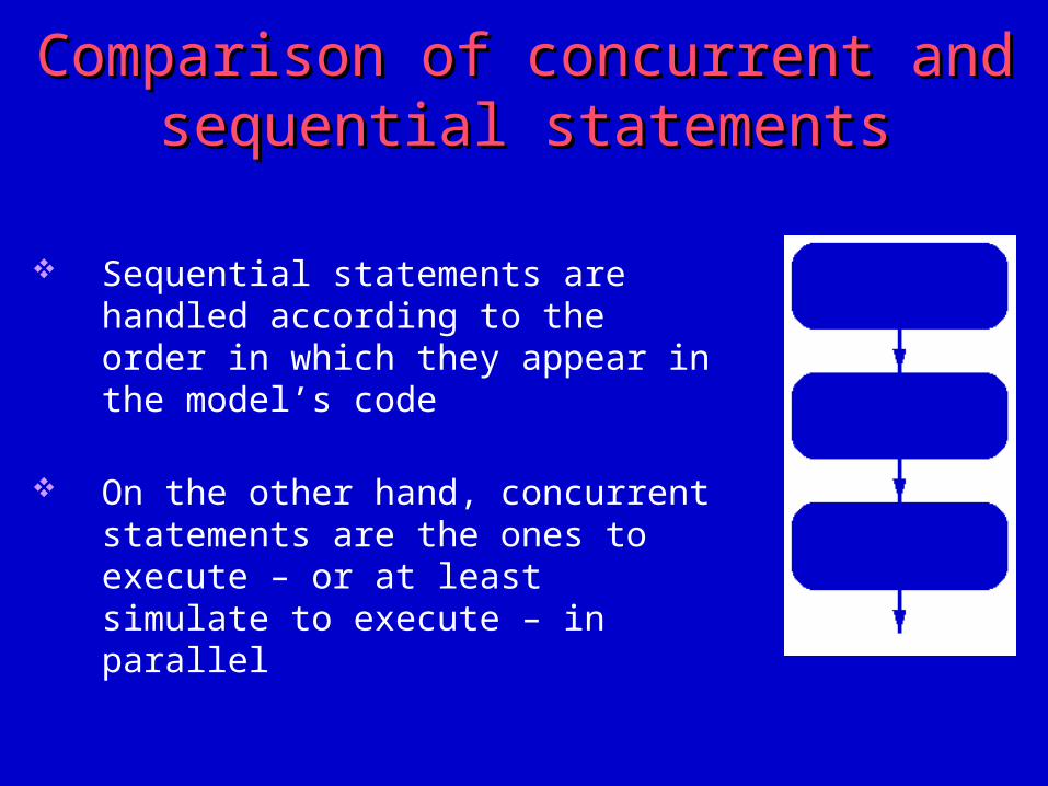
Sequential statements are handled according to the order in which they appear in the model’s code
On the other hand, concurrent statements are the ones to execute – or at least simulate to execute – in parallel
Comparison of concurrent and sequential Comparison of concurrent and sequential statementsstatements
Signal assignmentSignal assignment
Variables: sequential objects Signals: concurrent objects In hardware: it usually feels natural to work concurrently using signal
assignment statements Syntax:
<target_identifier> <= <selected_expression> ;
Simple exampleSimple example
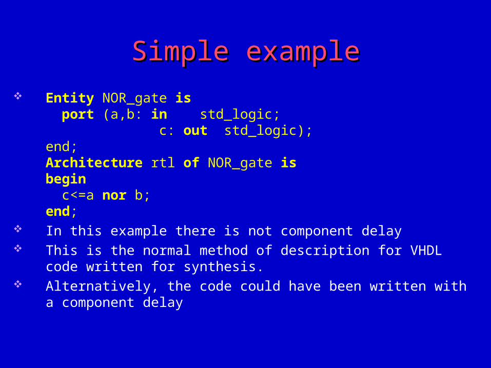
Entity NOR_gate is port (a,b: in std_logic; c: out std_logic);end;Architecture rtl of NOR_gate isbegin c<=a nor b;end;
In this example there is not component delay This is the normal method of description for VHDL code written for synthesis. Alternatively, the code could have been written with a component delay
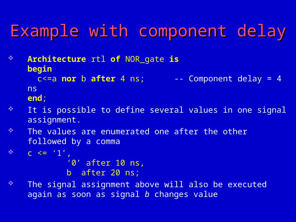
Example with component delay Example with component delay
Architecture rtl of NOR_gate isbegin c<=a nor b after 4 ns; -- Component delay = 4 nsend;
It is possible to define several values in one signal assignment. The values are enumerated one after the other followed by a comma c <= ‘1’,
‘0’ after 10 ns, b after 20 ns;
The signal assignment above will also be executed again as soon as signal b changes value
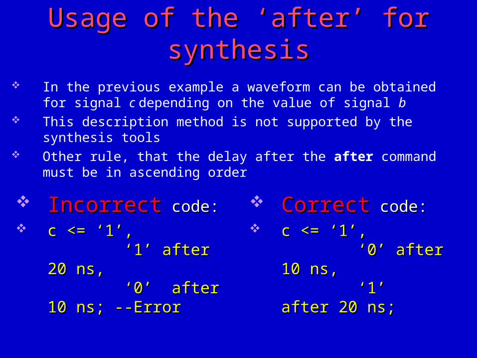
Usage of the ‘after’ for synthesisUsage of the ‘after’ for synthesis In the previous example a waveform can be obtained for signal c depending on
the value of signal b This description method is not supported by the synthesis tools Other rule, that the delay after the after command must be in ascending order
IncorrectIncorrect code: code: c <= ‘1’,c <= ‘1’,
‘1’ after 20 ns, ‘1’ after 20 ns, ‘0’ after 10 ns; --Error ‘0’ after 10 ns; --Error
CorrectCorrect code: code: c <= ‘1’,c <= ‘1’,
‘0’ after 10 ns, ‘0’ after 10 ns, ‘1’ after 20 ns; ‘1’ after 20 ns;
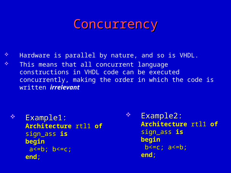
ConcurrencyConcurrency
Hardware is parallel by nature, and so is VHDL. This means that all concurrent language constructions in VHDL code can be
executed concurrently, making the order in which the code is written irrelevant
Example2:Example2:ArchitectureArchitecture rtl1 rtl1 ofof sign_ass sign_ass isisbeginbegin b<=c; a<=b; b<=c; a<=b;endend; ;
Example1:Example1:ArchitectureArchitecture rtl1 rtl1 ofof sign_ass sign_ass isisbeginbegin a<=b; b<=c; a<=b; b<=c;endend;;
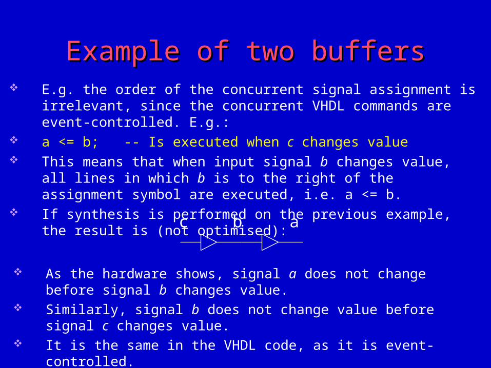
Example of two Example of two buffersbuffers
As the hardware shows, signal a does not change before signal b changes value.
Similarly, signal b does not change value before signal c changes value. It is the same in the VHDL code, as it is event-controlled. This means that all the concurrent VHDL commands can be written in any
order without the function of the design being changed
c b a
E.g. the order of the concurrent signal assignment is irrelevant, since the concurrent VHDL commands are event-controlled. E.g.:
a <= b; -- Is executed when c changes value This means that when input signal b changes value, all lines in which b is to the
right of the assignment symbol are executed, i.e. a <= b. If synthesis is performed on the previous example, the result is (not optimised):
LabelLabel
All concurrent statements can be identified with a label: Label_name: b <= a; This label is only used for documentation and has no functional significance. Unlike in some programming languages, it is not possible to jump to a label.
Delta time IDelta time I
Delta time is used in VHDL for “queuing up” sequential events. The time between two sequential events is called a delta delay. A delta delay has no equivalent in real time but is executed while the
simulation clock is standing still. In a signal assignment, the value is not assigned to the signal directly, but after
a delta at the earliest: b<=a; -- Signal b assign value of signal a after one delta delay. In a combinational logic block, where all elements have a 0 ns delay, all
assignments will take place at 0 ns, but it may contain many delta delays. The VHDL simulator will count up the number of delta times until all signals
are stable. If the VHDL code is written incorrectly, there is a risk that the design will
oscillate ad infinitum.
Delta time IIDelta time II
To prevent VHDL simulators jamming, most simulators stop after 1000 delta times, e.g.
The number can usually be set. The following example is correct VHDL, but generates a design which
oscillates ad infinitum:q<= not q;
Signal q will be updated to the inverse of itself after a delta time. This causes the line to be executed again, and q will be updated after another
delta time, etc. This problem is easy to solve by inserting a delay:
q<= not q after 10 ns; Note that, if the above code is synthesized, it will lead to asynchronous
feedback, which is not usually desirable in design.
When statementWhen statement
Syntax:<target> <= <expression> [after <expression>] when <condition> else
<expression> [after <expression>] when <condition> else... <expression>;
It is permissible to have several when else lines. The <target> signal must always be assigned a value irrespective of the value
of <expression>. This means that the command has to be ended with an else <expression>.
Examples for “when” statementExamples for “when” statement
Example:Entity ex is port (a,b,c: in std_logic; data: in std_logic-vector (1 downto 0);
q: out std_logic); end;Architecture rtl of ex isbegin q<=a when data=“00” else
b when data=“11” else c; end;
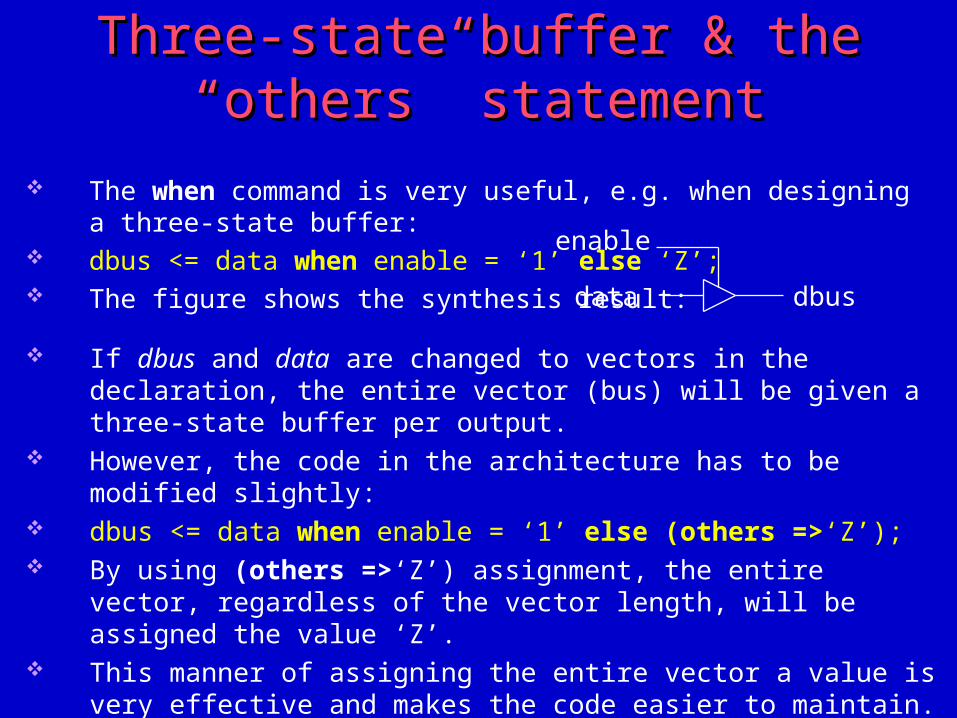
Three-state buffer & the “others” Three-state buffer & the “others” statementstatement
The when command is very useful, e.g. when designing a three-state buffer: dbus <= data when enable = ‘1’ else ‘Z’; The figure shows the synthesis result:
data dbus
enable
If dbus and data are changed to vectors in the declaration, the entire vector (bus) will be given a three-state buffer per output.
However, the code in the architecture has to be modified slightly: dbus <= data when enable = ‘1’ else (others =>‘Z’); By using (others =>‘Z’) assignment, the entire vector, regardless of the vector
length, will be assigned the value ‘Z’. This manner of assigning the entire vector a value is very effective and makes
the code easier to maintain. If the length of the vector is to be changed, only the declaration for the vectors
has to be modified and not the code in the architecture.
Detailed properties of the when statementDetailed properties of the when statement
It is permissible to use several different signals in the <condition> expression, making the command very flexible and useful for design.
Example:q <= a when en=‘0’ else b when data=“11” else c when enable=‘1’ else d;
Note that the conditions are checked in the order in which they are enumerated. The conditions are evaluated line by line until condition is true. This means that if line two (data=“11”) and line three (enable=‘1’), for example, are
transposed, the result, if both conditions are true simultaneously, will be different. Suppose, that en=‘0’, data=“11” and enable=‘1’. This means that q will be given the value of signal b in the above example. If lines two and three are transposed, q will be given the value signal c. It is only between concurrent commands that order is unimportant. Inside a concurrent command, e.g. in when else, order is important.
Upper-case and lower-case lettersUpper-case and lower-case letters
VHDL syntax does not differentiate between upper-case and lower-case letters.
The only exception is inside single quotation marks (‘ ‘) or double quotation marks (“ “), e.g. when the value ‘Z’ is assigned to a signal of type std_logic or mvl, the ‘Z’ must be upper-case:
sig <= ‘Z’; -- Goodsig <= ‘z’; -- Bad
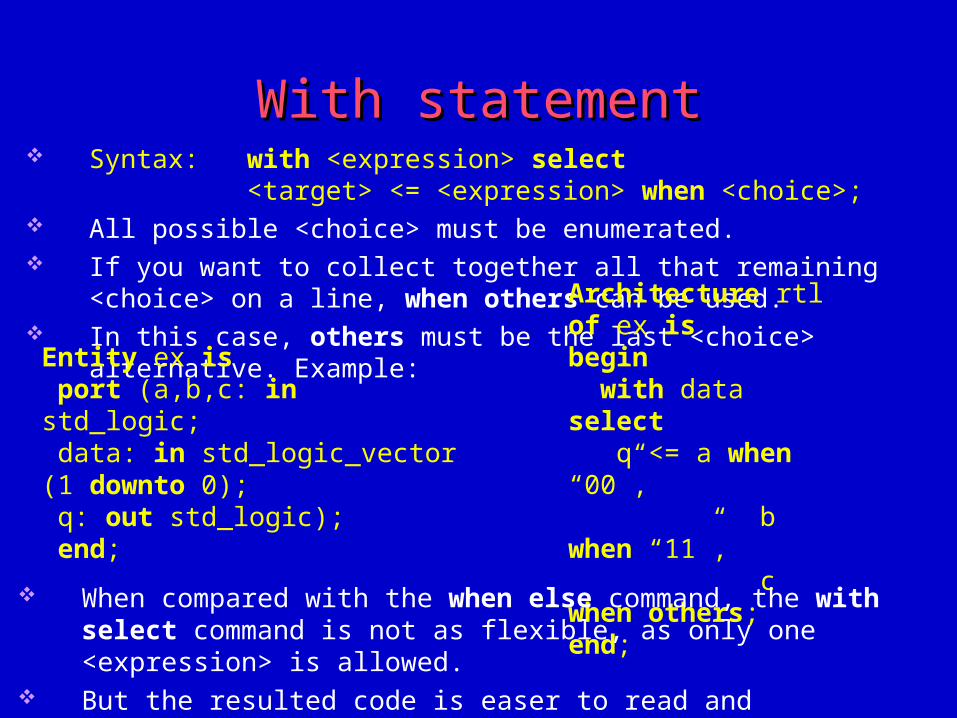
With statementWith statement Syntax: with <expression> select
<target> <= <expression> when <choice>; All possible <choice> must be enumerated. If you want to collect together all that remaining <choice> on a line, when
others can be used. In this case, others must be the last <choice> alternative. Example:
Entity ex is port (a,b,c: in std_logic; data: in std_logic_vector (1 downto 0); q: out std_logic); end;
Architecture rtl of ex isbegin with data select q <= a when “00”, b when “11”, c when others;end; When compared with the when else command, the with select command is not
as flexible, as only one <expression> is allowed. But the resulted code is easer to read and structured.
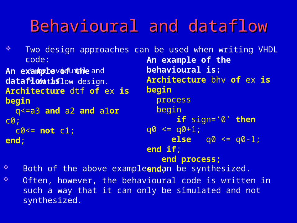
Behavioural and dataflowBehavioural and dataflow Two design approaches can be used when writing VHDL code:
behavioural and dataflow design.
An example of the dataflow is:Architecture dtf of ex isbegin q<=a3 and a2 and a1or c0; c0<= not c1;end;
An example of the behavioural is:Architecture bhv of ex isbegin process begin if sign=‘0’ then q0 <= q0+1; else q0 <= q0-1; end if; end process;end;
Both of the above examples can be synthesized. Often, however, the behavioural code is written in such a way that it can only
be simulated and not synthesized.
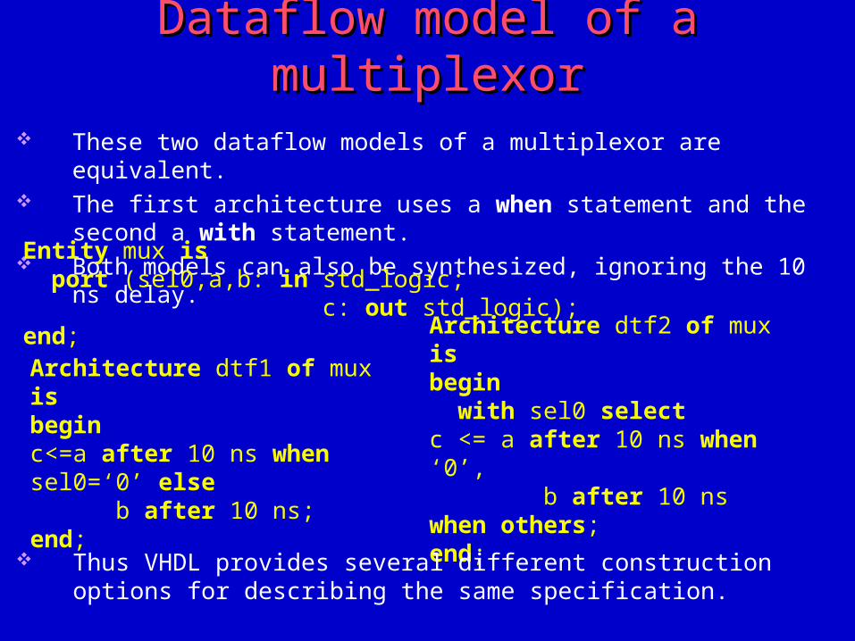
Dataflow model of a multiplexorDataflow model of a multiplexor These two dataflow models of a multiplexor are equivalent. The first architecture uses a when statement and the second a with statement. Both models can also be synthesized, ignoring the 10 ns delay.
Entity mux is port (sel0,a,b: in std_logic; c: out std_logic);end;
Architecture dtf1 of mux isbegin c<=a after 10 ns when sel0=‘0’ else b after 10 ns;end;
Architecture dtf2 of mux isbegin with sel0 selectc <= a after 10 ns when ‘0’, b after 10 ns when others;end;
Thus VHDL provides several different construction options for describing the same specification.
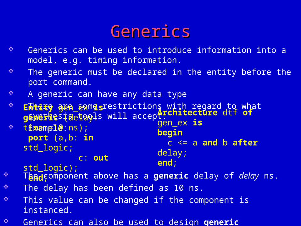
GenericsGenerics Generics can be used to introduce information into a model, e.g. timing
information. The generic must be declared in the entity before the port command. A generic can have any data type There are some restrictions with regard to what synthesis tools will accept. Example:
Entity gen_ex isgeneric (delay: time:=10 ns); port (a,b: in std_logic; c: out std_logic); end;
Architecture dtf of gen_ex isbegin c <= a and b after delay;end;
The component above has a generic delay of delay ns. The delay has been defined as 10 ns. This value can be changed if the component is instanced. Generics can also be used to design generic components.
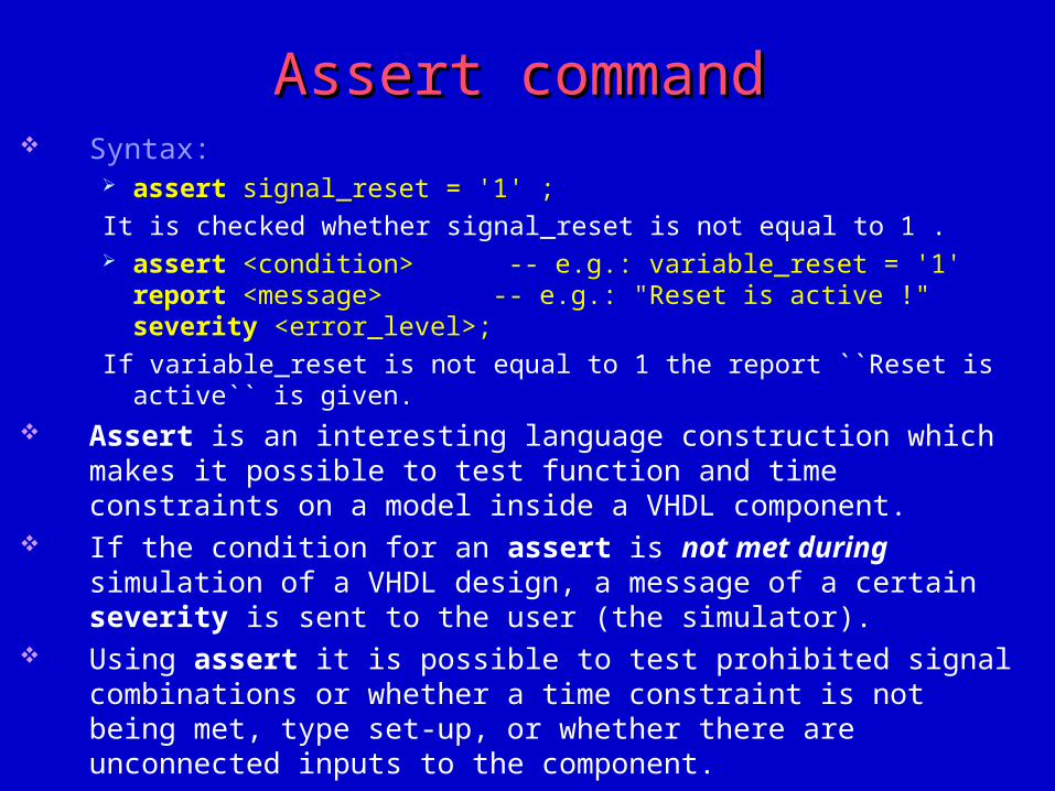
Assert commandAssert command Syntax:
assert signal_reset = '1' ;
It is checked whether signal_reset is not equal to 1 . assert <condition> -- e.g.: variable_reset = '1'
report <message> -- e.g.: "Reset is active !"severity <error_level>;
If variable_reset is not equal to 1 the report ``Reset is active`` is given. Assert is an interesting language construction which makes it possible to test
function and time constraints on a model inside a VHDL component. If the condition for an assert is not met during simulation of a VHDL design,
a message of a certain severity is sent to the user (the simulator). Using assert it is possible to test prohibited signal combinations or whether a
time constraint is not being met, type set-up, or whether there are unconnected inputs to the component.
If the condition is not met, the assert message is sent to the user plus the name of the (unit) process which was cancelled.
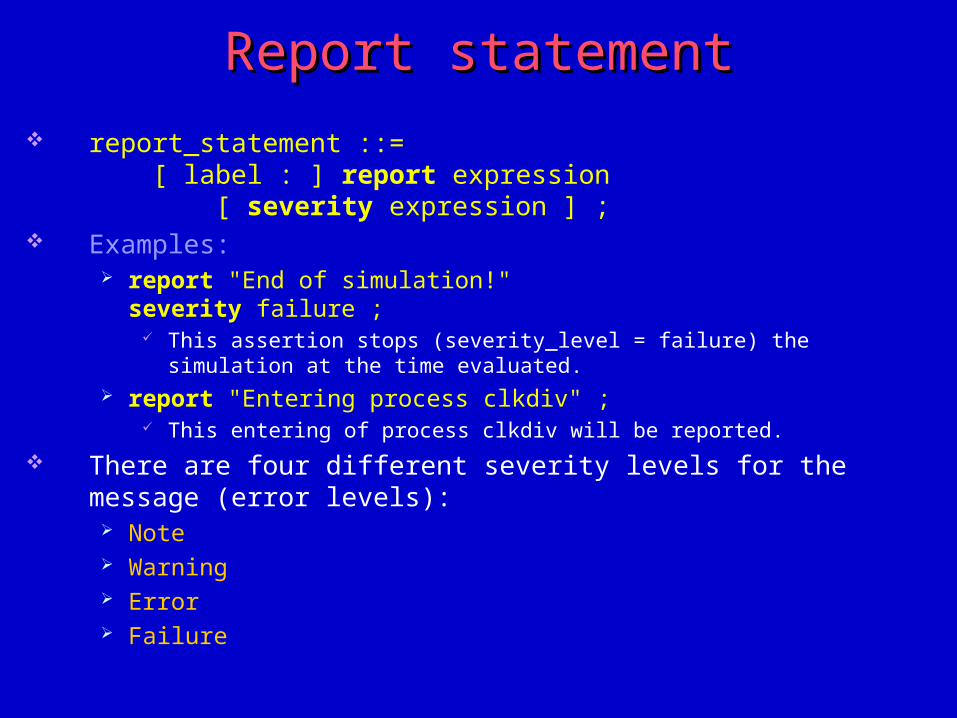
Report statementReport statement
report_statement ::= [ label : ] report expression [ severity expression ] ;
Examples: report "End of simulation!"
severity failure ; This assertion stops (severity_level = failure) the simulation at the time evaluated.
report "Entering process clkdiv" ; This entering of process clkdiv will be reported.
There are four different severity levels for the message (error levels): Note Warning Error Failure
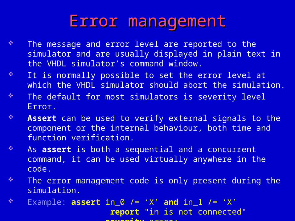
Error managementError management The message and error level are reported to the simulator and are usually
displayed in plain text in the VHDL simulator’s command window. It is normally possible to set the error level at which the VHDL simulator
should abort the simulation. The default for most simulators is severity level Error. Assert can be used to verify external signals to the component or the internal
behaviour, both time and function verification. As assert is both a sequential and a concurrent command, it can be used
virtually anywhere in the code. The error management code is only present during the simulation. Example: assert in_0 /= ‘X’ and in_1 /= ‘X’
report "in is not connected" severity error;
The error management code checks that in_0 and in_1 are connected, or that they have an undefined value.
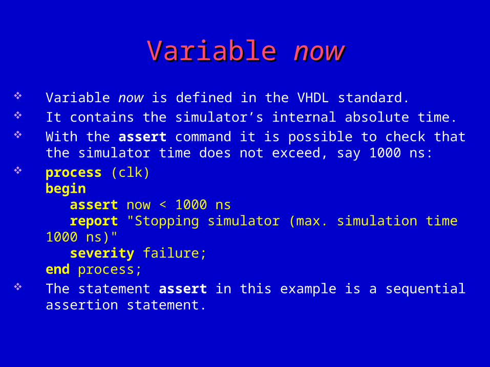
Variable Variable nownow
Variable now is defined in the VHDL standard. It contains the simulator’s internal absolute time. With the assert command it is possible to check that the simulator time does
not exceed, say 1000 ns: process (clk)
begin assert now < 1000 ns report "Stopping simulator (max. simulation time 1000 ns)" severity failure;end process;
The statement assert in this example is a sequential assertion statement.
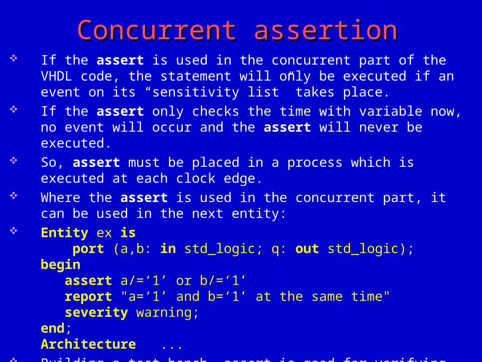
Concurrent assertionConcurrent assertion If the assert is used in the concurrent part of the VHDL code, the statement
will only be executed if an event on its “sensitivity list” takes place. If the assert only checks the time with variable now, no event will occur and
the assert will never be executed. So, assert must be placed in a process which is executed at each clock edge. Where the assert is used in the concurrent part, it can be used in the next
entity: Entity ex is
port (a,b: in std_logic; q: out std_logic);begin assert a/=‘1’ or b/=‘1’ report "a=‘1’ and b=‘1’ at the same time" severity warning;end;Architecture ...
Building a test bench, assert is good for verifying the response from the circuit.
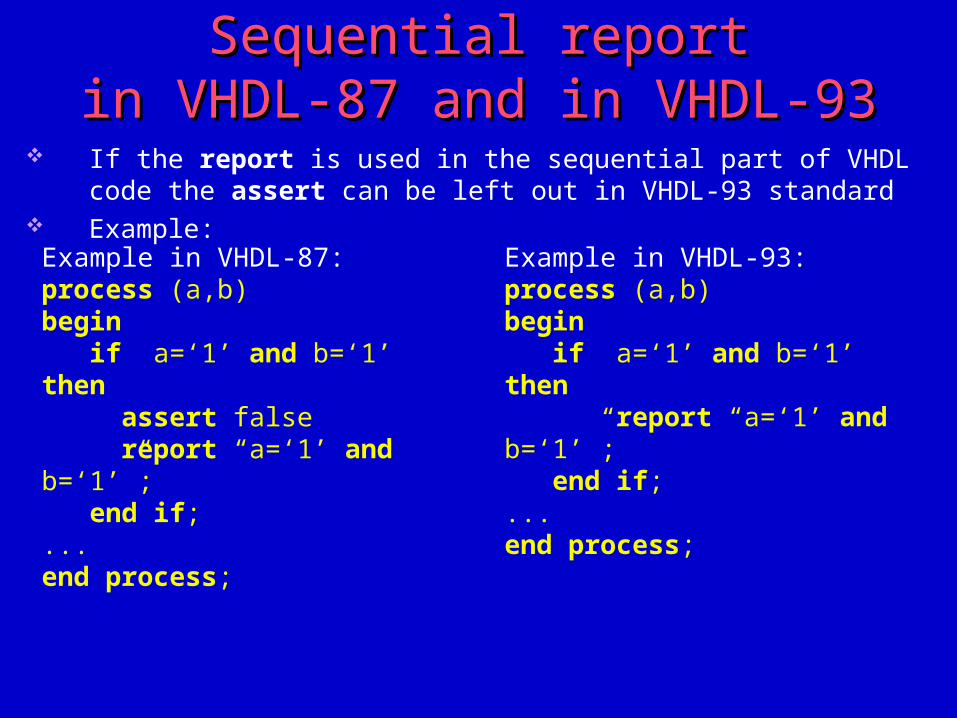
Sequential reportSequential reportin VHDL-87 and in VHDL-93in VHDL-87 and in VHDL-93
If the report is used in the sequential part of VHDL code the assert can be left out in VHDL-93 standard
Example:
Example in VHDL-87: process (a,b)begin if a=‘1’ and b=‘1’ then assert false report “a=‘1’ and b=‘1’”; end if;...end process;
Example in VHDL-93: process (a,b)begin if a=‘1’ and b=‘1’ then report “a=‘1’ and b=‘1’”; end if;...end process;
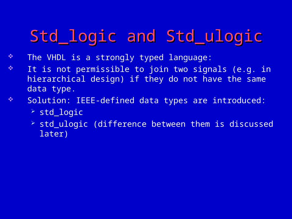
Std_logic and Std_ulogicStd_logic and Std_ulogic The VHDL is a strongly typed language: It is not permissible to join two signals (e.g. in hierarchical design) if they do
not have the same data type. Solution: IEEE-defined data types are introduced:
std_logic std_ulogic (difference between them is discussed later)
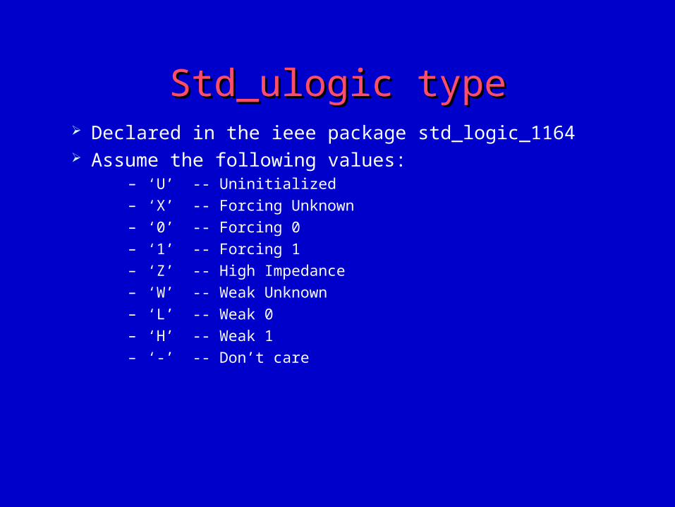
Std_ulogic typeStd_ulogic type Declared in the ieee package std_logic_1164 Assume the following values:
– ‘U’ -- Uninitialized
– ‘X’ -- Forcing Unknown
– ‘0’ -- Forcing 0
– ‘1’ -- Forcing 1
– ‘Z’ -- High Impedance
– ‘W’ -- Weak Unknown
– ‘L’ -- Weak 0
– ‘H’ -- Weak 1
– ‘-’ -- Don’t care
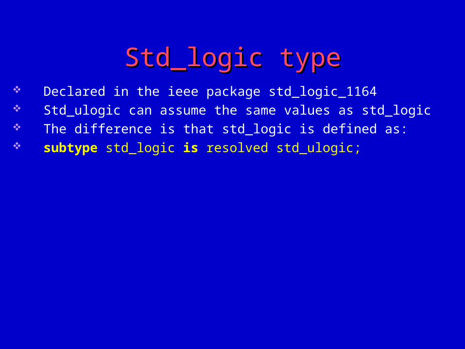
Std_logic typeStd_logic type Declared in the ieee package std_logic_1164 Std_ulogic can assume the same values as std_logic The difference is that std_logic is defined as: subtype std_logic is resolved std_ulogic;
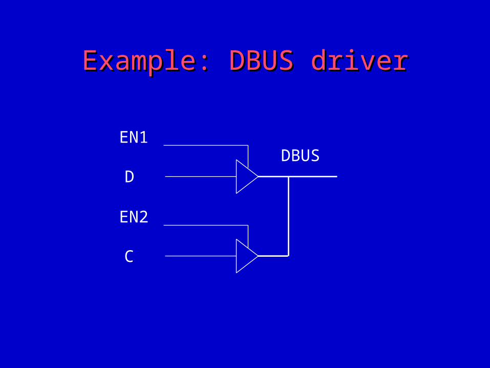
Example: DBUS driverExample: DBUS driver
EN2
C
EN1
DDBUS
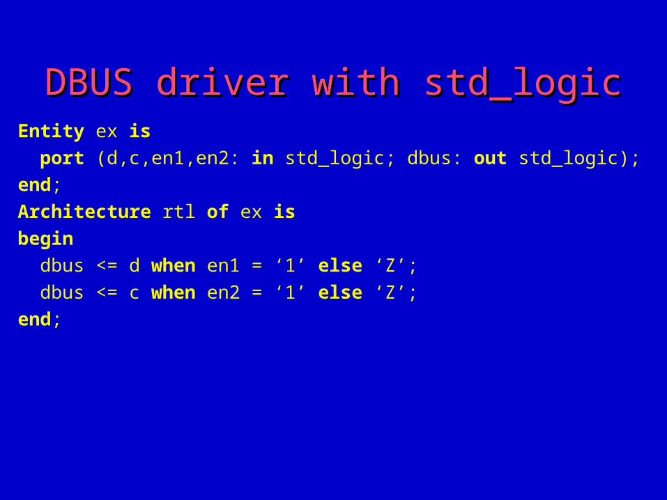
DBUS driver with std_logicDBUS driver with std_logicEntity ex is
port (d,c,en1,en2: in std_logic; dbus: out std_logic);
end;
Architecture rtl of ex is
begin
dbus <= d when en1 = ‘1’ else ‘Z’;
dbus <= c when en2 = ‘1’ else ‘Z’;
end;
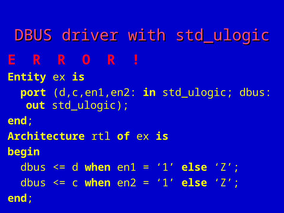
DBUS driver with std_ulogicDBUS driver with std_ulogic
E R R O R !Entity ex is
port (d,c,en1,en2: in std_ulogic; dbus: out std_ulogic);
end;
Architecture rtl of ex is
begin
dbus <= d when en1 = ‘1’ else ‘Z’;
dbus <= c when en2 = ‘1’ else ‘Z’;
end;
ComparisonComparison
Std_logic is preferred, since easiest to use the same data type throughout the design
The disadvantage, that no error occurs if you have two drivers for the same signal in the VHDL code by mistake
Composite types - ArrayComposite types - Array A named array is a collection of elements that are of the same type. Arrays may be configured in one or more dimensions. Each array element is referenced by one or more index value. Example:
type array_10 is array (0 to 9) of integer;
Array type examplesArray type examples Std_ulogic_vector is defined as:
type std_ulogic_vector is array (natural range <>) of std_ulogic; Std_logic_vector is defined as:
type std_logic_vector is array (natural range <>) of std_logic; Bit_vector is defined as:
type bit_vector is array (natural range <>) of bit; Vlbit_vector is defined as:
type vlbit_vector is array (natural range <>) of vlbit;
Enumerated typeEnumerated type It is possible to define the own data types in VHDL. In principle, these data types can assume any value whatsoever. State machines are a common area of use for enumerated data types. Example:
type state_type is (red, yellow, green); signal trafficlight: state_type; In VHDL simulation, the signal trafficlight will then be given one of its three
defined values which are displayed in the waveform windows of the simulator. These self-explanatory signal names make it easier to simulate the design. The majority of synthesis tools also support enumerated data types. In this example, state will be converted to a 2-bit vector by the synthesis tool,
as it could assume three different values.
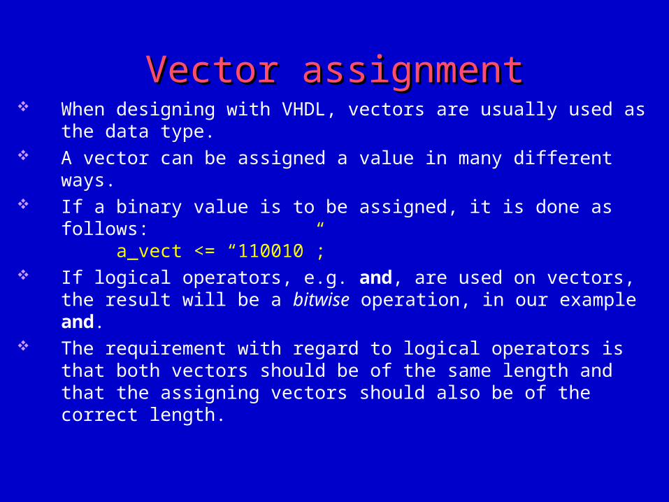
Vector assignmentVector assignment When designing with VHDL, vectors are usually used as the data type. A vector can be assigned a value in many different ways. If a binary value is to be assigned, it is done as follows:
a_vect <= “110010”; If logical operators, e.g. and, are used on vectors, the result will be a bitwise
operation, in our example and. The requirement with regard to logical operators is that both vectors should be
of the same length and that the assigning vectors should also be of the correct length.
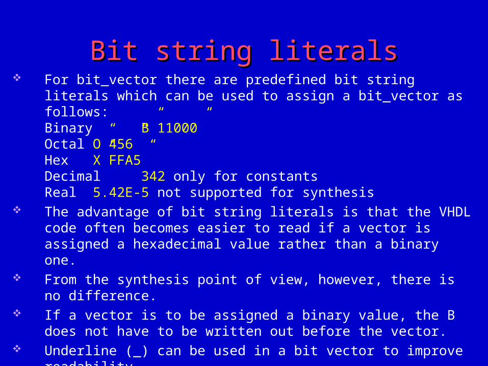
Bit string literalsBit string literals For bit_vector there are predefined bit string literals which can be used to
assign a bit_vector as follows:Binary B”11000”Octal O”456”Hex X”FFA5”Decimal 342 only for constantsReal 5.42E-5 not supported for synthesis
The advantage of bit string literals is that the VHDL code often becomes easier to read if a vector is assigned a hexadecimal value rather than a binary one.
From the synthesis point of view, however, there is no difference. If a vector is to be assigned a binary value, the B does not have to be written
out before the vector. Underline (_) can be used in a bit vector to improve readability. If underline is used, bit string literals must be written out.
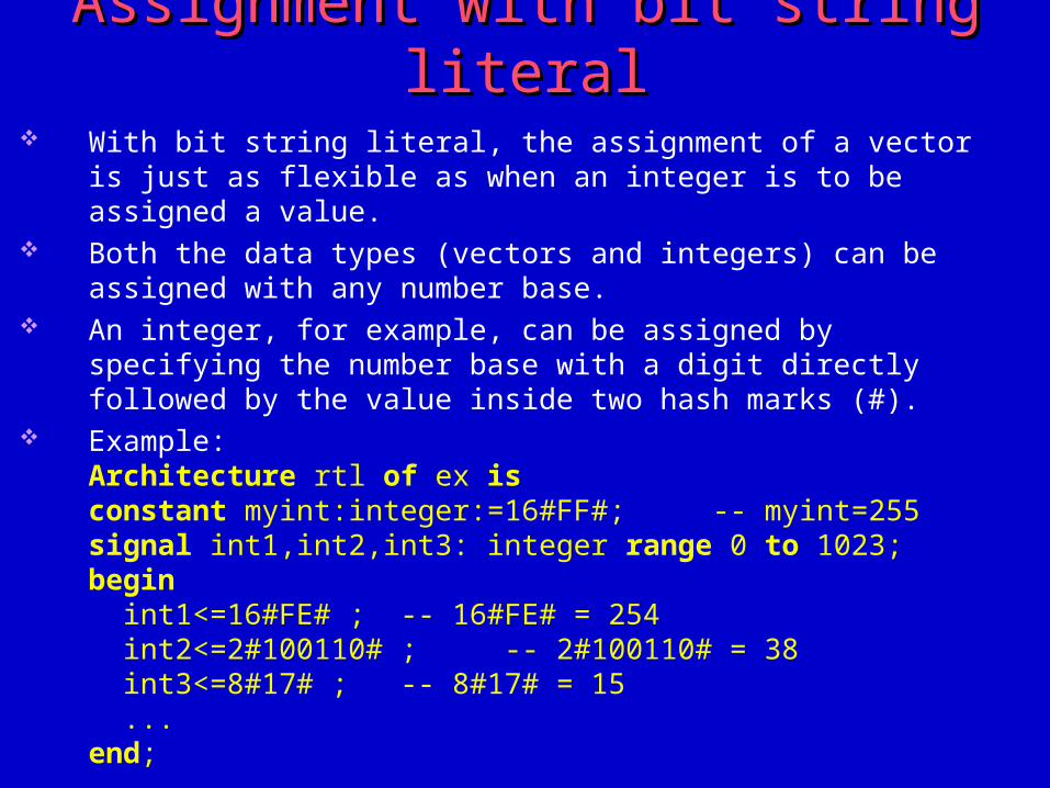
Assignment with bit string literalAssignment with bit string literal With bit string literal, the assignment of a vector is just as flexible as when an
integer is to be assigned a value. Both the data types (vectors and integers) can be assigned with any number
base. An integer, for example, can be assigned by specifying the number base with a
digit directly followed by the value inside two hash marks (#). Example:
Architecture rtl of ex isconstant myint:integer:=16#FF#; -- myint=255signal int1,int2,int3: integer range 0 to 1023;begin int1<=16#FE# ; -- 16#FE# = 254 int2<=2#100110# ; -- 2#100110# = 38 int3<=8#17# ; -- 8#17# = 15 ...end;
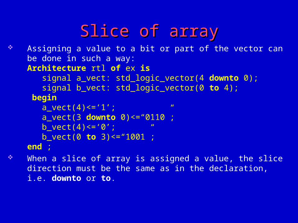
Slice of arraySlice of array Assigning a value to a bit or part of the vector can be done in such a way:
Architecture rtl of ex is signal a_vect: std_logic_vector(4 downto 0); signal b_vect: std_logic_vector(0 to 4); begin a_vect(4)<=‘1’; a_vect(3 downto 0)<=“0110”; b_vect(4)<=‘0’; b_vect(0 to 3)<=“1001”;end ;
When a slice of array is assigned a value, the slice direction must be the same as in the declaration, i.e. downto or to.
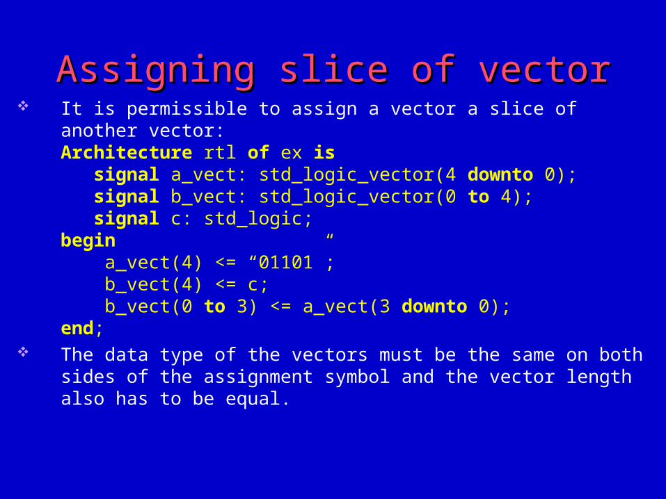
Assigning slice of vectorAssigning slice of vector It is permissible to assign a vector a slice of another vector:
Architecture rtl of ex is signal a_vect: std_logic_vector(4 downto 0); signal b_vect: std_logic_vector(0 to 4); signal c: std_logic;begin a_vect(4) <= “01101”; b_vect(4) <= c; b_vect(0 to 3) <= a_vect(3 downto 0);end;
The data type of the vectors must be the same on both sides of the assignment symbol and the vector length also has to be equal.
Assigning vectors with different index Assigning vectors with different index orderorder
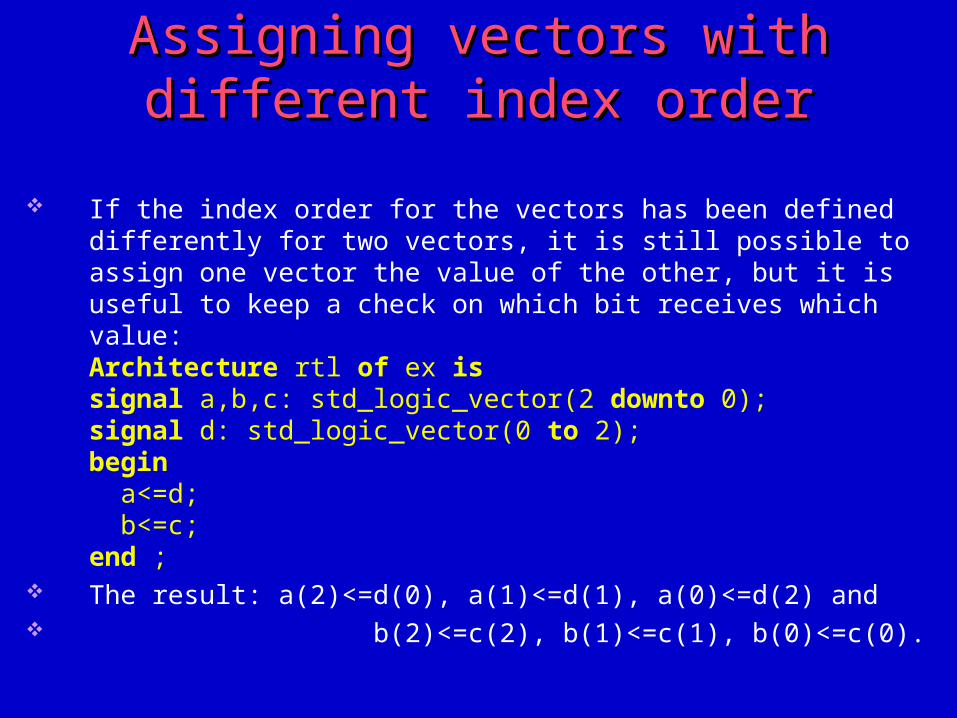
If the index order for the vectors has been defined differently for two vectors, it is still possible to assign one vector the value of the other, but it is useful to keep a check on which bit receives which value:Architecture rtl of ex issignal a,b,c: std_logic_vector(2 downto 0);signal d: std_logic_vector(0 to 2); begin a<=d; b<=c;end ;
The result: a(2)<=d(0), a(1)<=d(1), a(0)<=d(2) and b(2)<=c(2), b(1)<=c(1), b(0)<=c(0).
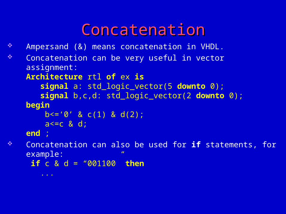
ConcatenationConcatenation Ampersand (&) means concatenation in VHDL. Concatenation can be very useful in vector assignment:
Architecture rtl of ex is signal a: std_logic_vector(5 downto 0); signal b,c,d: std_logic_vector(2 downto 0); begin b<=‘0’ & c(1) & d(2); a<=c & d;end ;
Concatenation can also be used for if statements, for example: if c & d = “001100” then ...
Example for bad usage of the Example for bad usage of the concatenationconcatenation
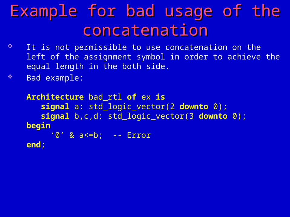
It is not permissible to use concatenation on the left of the assignment symbol in order to achieve the equal length in the both side.
Bad example:
Architecture bad_rtl of ex is signal a: std_logic_vector(2 downto 0); signal b,c,d: std_logic_vector(3 downto 0); begin ‘0’ & a<=b; -- Errorend;
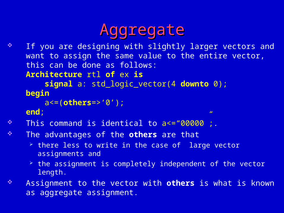
AggregateAggregate If you are designing with slightly larger vectors and want to assign the same
value to the entire vector, this can be done as follows:Architecture rtl of ex is signal a: std_logic_vector(4 downto 0);begin a<=(others=>‘0’);end;
This command is identical to a<=“00000”;. The advantages of the others are that
there less to write in the case of large vector assignments and the assignment is completely independent of the vector length.
Assignment to the vector with others is what is known as aggregate assignment.
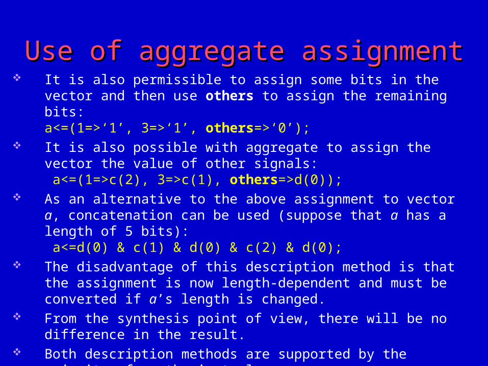
Use of aggregate assignmentUse of aggregate assignment It is also permissible to assign some bits in the vector and then use others to
assign the remaining bits:a<=(1=>‘1’, 3=>‘1’, others=>‘0’);
It is also possible with aggregate to assign the vector the value of other signals: a<=(1=>c(2), 3=>c(1), others=>d(0));
As an alternative to the above assignment to vector a, concatenation can be used (suppose that a has a length of 5 bits): a<=d(0) & c(1) & d(0) & c(2) & d(0);
The disadvantage of this description method is that the assignment is now length-dependent and must be converted if a’s length is changed.
From the synthesis point of view, there will be no difference in the result. Both description methods are supported by the majority of synthesis tools.
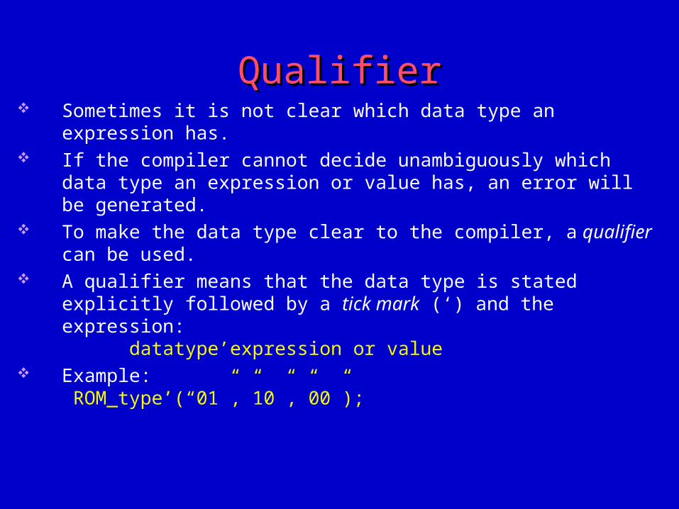
QualifierQualifier Sometimes it is not clear which data type an expression has. If the compiler cannot decide unambiguously which data type an expression or
value has, an error will be generated. To make the data type clear to the compiler, a qualifier can be used. A qualifier means that the data type is stated explicitly followed by a tick mark
(‘) and the expression:datatype’expression or value
Example: ROM_type’(“01”,”10”,”00”);
Advanced data typesAdvanced data types
For advanced design, access to most advanced data types is needed.
There follows a look at multidimensional data types subtypes and records
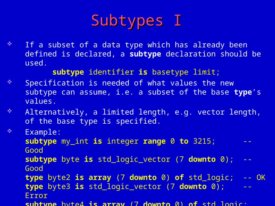
Subtypes ISubtypes I If a subset of a data type which has already been defined is declared, a subtype
declaration should be used.subtype identifier is basetype limit;
Specification is needed of what values the new subtype can assume, i.e. a subset of the base type’s values.
Alternatively, a limited length, e.g. vector length, of the base type is specified. Example:
subtype my_int is integer range 0 to 3215; -- Goodsubtype byte is std_logic_vector (7 downto 0); -- Goodtype byte2 is array (7 downto 0) of std_logic; -- OKtype byte3 is std_logic_vector (7 downto 0); -- Errorsubtype byte4 is array (7 downto 0) of std_logic; -- Error
The array can only be used to define new types and not subtypes. Std_logic_vector(7 downto 0) cannot be used in new type declarations
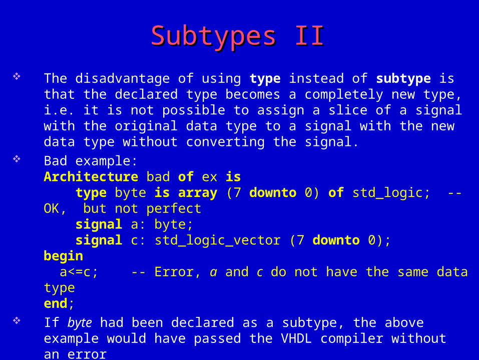
Subtypes IISubtypes II The disadvantage of using type instead of subtype is that the declared type
becomes a completely new type, i.e. it is not possible to assign a slice of a signal with the original data type to a signal with the new data type without converting the signal.
Bad example:Architecture bad of ex is type byte is array (7 downto 0) of std_logic; -- OK, but not perfect signal a: byte; signal c: std_logic_vector (7 downto 0);begin a<=c; -- Error, a and c do not have the same data typeend;
If byte had been declared as a subtype, the above example would have passed the VHDL compiler without an error
The usage of the subtypes is practical, since the functions, which handle a given types, can be used for its subtypes, too
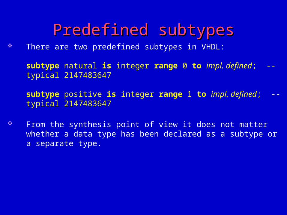
Predefined subtypesPredefined subtypes There are two predefined subtypes in VHDL:
subtype natural is integer range 0 to impl. defined; -- typical 2147483647
subtype positive is integer range 1 to impl. defined; -- typical 2147483647
From the synthesis point of view it does not matter whether a data type has been declared as a subtype or a separate type.
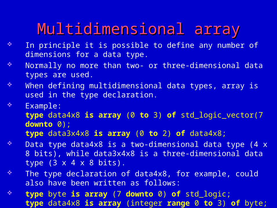
Multidimensional arrayMultidimensional array In principle it is possible to define any number of dimensions for a data type. Normally no more than two- or three-dimensional data types are used. When defining multidimensional data types, array is used in the type
declaration. Example:
type data4x8 is array (0 to 3) of std_logic_vector(7 downto 0);type data3x4x8 is array (0 to 2) of data4x8;
Data type data4x8 is a two-dimensional data type (4 x 8 bits), while data3x4x8 is a three-dimensional data type (3 x 4 x 8 bits).
The type declaration of data4x8, for example, could also have been written as follows:
type byte is array (7 downto 0) of std_logic;type data4x8 is array (integer range 0 to 3) of byte;
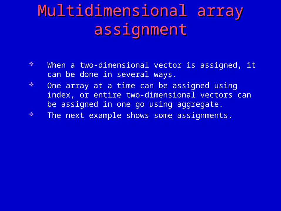
Multidimensional array assignmentMultidimensional array assignment
When a two-dimensional vector is assigned, it can be done in several ways.
One array at a time can be assigned using index, or entire two-dimensional vectors can be assigned in one go using aggregate.
The next example shows some assignments.
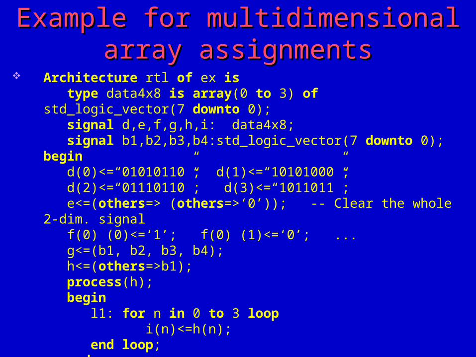
Example for multidimensional array Example for multidimensional array assignmentsassignments
Architecture rtl of ex is type data4x8 is array(0 to 3) of std_logic_vector(7 downto 0); signal d,e,f,g,h,i: data4x8; signal b1,b2,b3,b4:std_logic_vector(7 downto 0);begin d(0)<=“01010110”; d(1)<=“10101000”; d(2)<=“01110110”; d(3)<=“1011011”; e<=(others=> (others=>‘0’)); -- Clear the whole 2-dim. signal f(0) (0)<=‘1’; f(0) (1)<=‘0’; ... g<=(b1, b2, b3, b4); h<=(others=>b1); process(h); begin l1: for n in 0 to 3 loop i(n)<=h(n); end loop; end process;end;
About the multidimensional assignmentsAbout the multidimensional assignments
The assignment method to be chosen is dependent on the application and the readability required.
The majority of synthesis tools which support two-dimensional data types support all the previous methods.
The choice does not usually matter from a synthesis point of view.
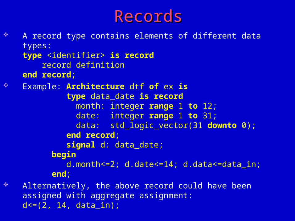
RecordsRecords A record type contains elements of different data types:
type <identifier> is record record definitionend record;
Example: Architecture dtf of ex is type data_date is record month: integer range 1 to 12; date: integer range 1 to 31; data: std_logic_vector(31 downto 0); end record; signal d: data_date;begin d.month<=2; d.date<=14; d.data<=data_in;end;
Alternatively, the above record could have been assigned with aggregate assignment:d<=(2, 14, data_in);
AliasAlias
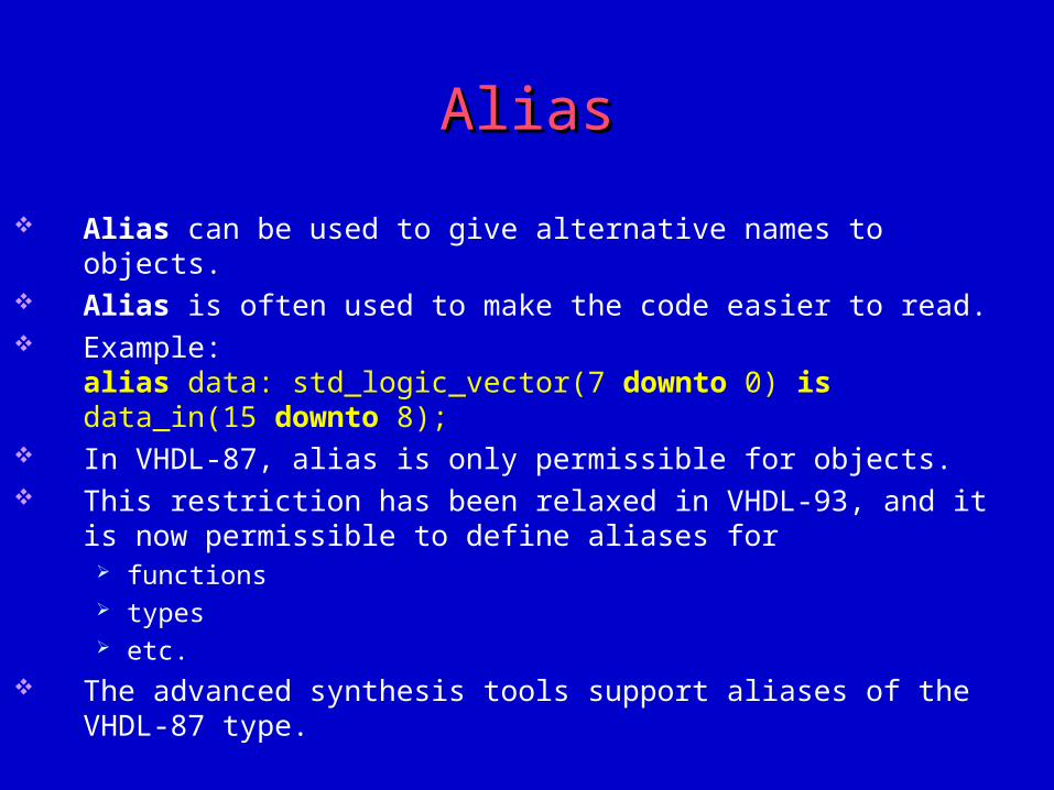
Alias can be used to give alternative names to objects. Alias is often used to make the code easier to read. Example:
alias data: std_logic_vector(7 downto 0) is data_in(15 downto 8); In VHDL-87, alias is only permissible for objects. This restriction has been relaxed in VHDL-93, and it is now permissible to
define aliases for functions types etc.
The advanced synthesis tools support aliases of the VHDL-87 type.
Relational operatorsRelational operators
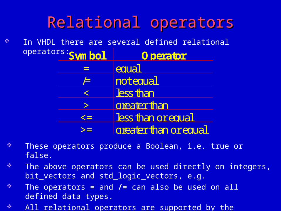
These operators produce a Boolean, i.e. true or false. The above operators can be used directly on integers, bit_vectors and
std_logic_vectors, e.g. The operators = and /= can also be used on all defined data types. All relational operators are supported by the majority of the synthesis tools.
Symbol Operator= equal/= not equal< less than> greater than<= less than or equal>= greater than or equal
In VHDL there are several defined relational operators:
Arithmetic operatorsArithmetic operators
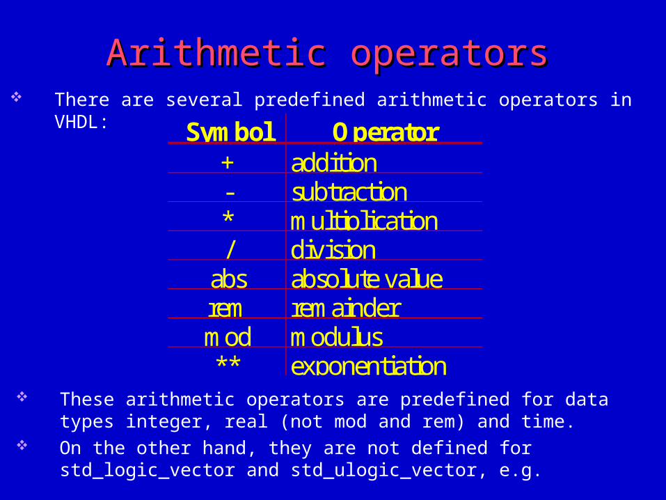
These arithmetic operators are predefined for data types integer, real (not mod and rem) and time.
On the other hand, they are not defined for std_logic_vector and std_ulogic_vector, e.g.
Symbol Operator+ addition- subtraction* multiplication/ division
abs absolute valuerem remaindermod modulus** exponentiation
There are several predefined arithmetic operators in VHDL:

Arithmetic operators with std_logicArithmetic operators with std_logic If std_logic_vectors have to use the previous operators, they must be defined
for std_logic_vector, e.g. in a so called package. This has already been done in package ieee.std_logic_unsigned, e.g.
The majority of synthesis tools support “+”, “-” and “*” for integers. However, they are not supported for data types real and time. As far as operators for std_logic_vector are concerned, for example, the
advanced synthesis tools support “+”, “-”, “*” and “**”. Something which may vary is the package which the synthesis tool supports,
i.e. where its operators for std_logic_vectors are defined. Something else which may need to be altered if the synthesis tool is changed is
the package which has to be declared at the top of the VHDL code with regard to arithmetic operators.
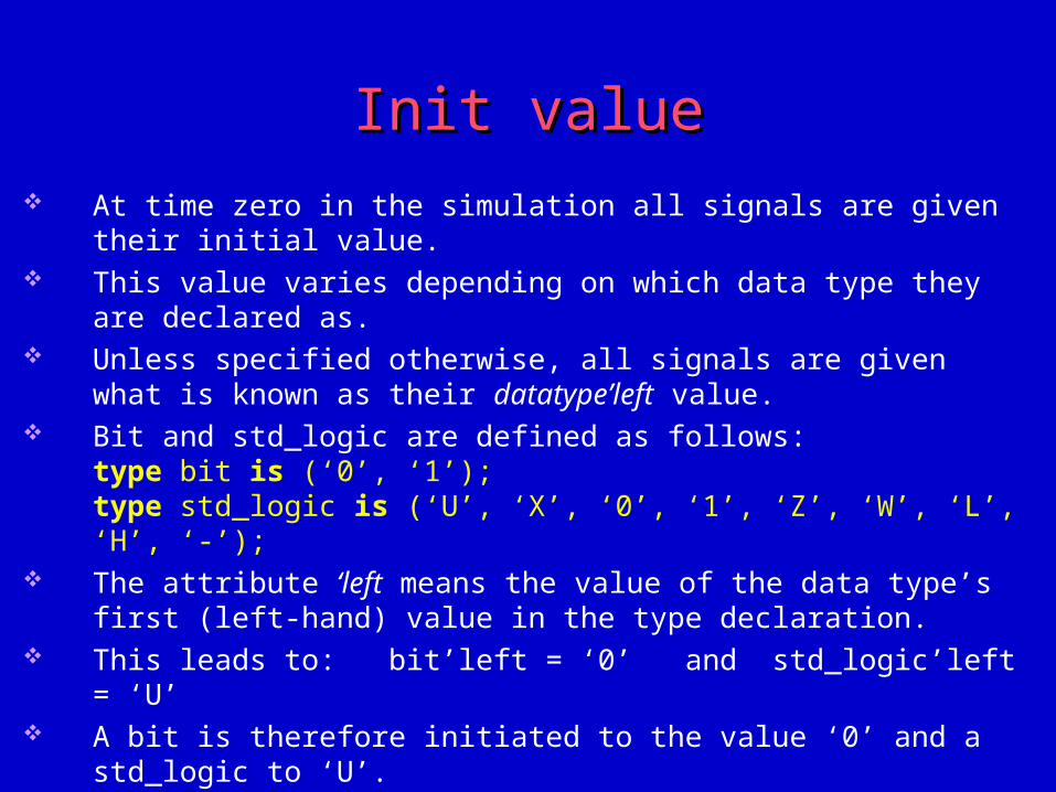
Init valueInit value At time zero in the simulation all signals are given their initial value. This value varies depending on which data type they are declared as. Unless specified otherwise, all signals are given what is known as their
datatype’left value. Bit and std_logic are defined as follows:
type bit is (‘0’, ‘1’);type std_logic is (‘U’, ‘X’, ‘0’, ‘1’, ‘Z’, ‘W’, ‘L’, ‘H’, ‘-’);
The attribute ‘left means the value of the data type’s first (left-hand) value in the type declaration.
This leads to: bit’left = ‘0’ and std_logic’left = ‘U’ A bit is therefore initiated to the value ‘0’ and a std_logic to ‘U’. If you want to know what a data type is initiated to, you must know how that
data type is declared.
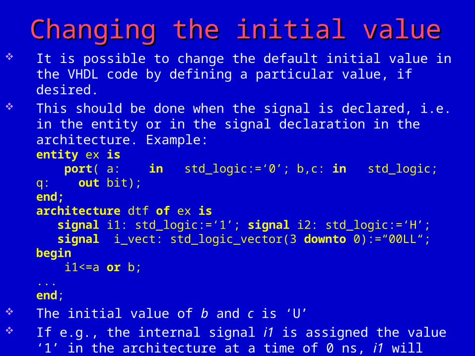
Changing the initial valueChanging the initial value It is possible to change the default initial value in the VHDL code by defining a
particular value, if desired. This should be done when the signal is declared, i.e. in the entity or in the
signal declaration in the architecture. Example:entity ex is port( a: in std_logic:=‘0’; b,c: in std_logic; q: out bit);end;architecture dtf of ex is signal i1: std_logic:=‘1’; signal i2: std_logic:=‘H’; signal i_vect: std_logic_vector(3 downto 0):=“00LL“;begin i1<=a or b;...end;
The initial value of b and c is ‘U’ If e.g., the internal signal i1 is assigned the value ‘1’ in the architecture at a
time of 0 ns, i1 will have the value ‘1’ during a delta and then be given the value ‘0’ at a time of 0 ns + 1 delta.
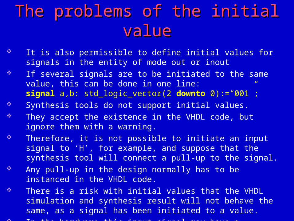
The problems of the initial valueThe problems of the initial value It is also permissible to define initial values for signals in the entity of mode
out or inout If several signals are to be initiated to the same value, this can be done in one
line:signal a,b: std_logic_vector(2 downto 0):=“001”;
Synthesis tools do not support initial values. They accept the existence in the VHDL code, but ignore them with a warning. Therefore, it is not possible to initiate an input signal to ‘H’, for example, and
suppose that the synthesis tool will connect a pull-up to the signal. Any pull-up in the design normally has to be instanced in the VHDL code. There is a risk with initial values that the VHDL simulation and synthesis
result will not behave the same, as a signal has been initiated to a value. In the hardware this input signal may have a different value at start-up, which
can lead to a “mismatch” between VHDL simulation and gate-level simulation.
ExerciseExercise
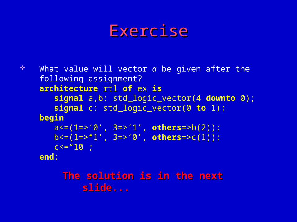
What value will vector a be given after the following assignment?architecture rtl of ex is signal a,b: std_logic_vector(4 downto 0); signal c: std_logic_vector(0 to 1);begin a<=(1=>‘0’, 3=>‘1’, others=>b(2)); b<=(1=>‘1’, 3=>‘0’, others=>c(1)); c<=“10”;end;
The solution is in the next slide...The solution is in the next slide...
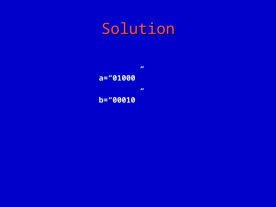
SolutionSolution
a=“01000”
b=“00010”