


Languages
Pages
Legal

Approved Continuing Education for Licensed Professional Engineers
Fundamentals of Fiber Optics
Three (3) Continuing Education Hours Course EE1201
EZ-pdhcom Ezekiel Enterprises LLC
301 Mission Dr Unit 571 New Smyrna Beach FL 32170
800-433-1487 helpdeskezpdhcom
Fundamentals of Fiber Optics Ezekiel Enterprises LLC
ii
Course Description
The Fundamentals of Fiber Optics course satisfies three (3) hours of professional development
The course is designed as a distance learning course that overviews the theory and concepts of fiber optics
Objectives
The primary objective of this course is to enable the student to understand fiber optics concepts and the theories of operation as well as gain a basic understanding of common components and the physics of light
Grading
Students must achieve a minimum score of 70 on the online quiz to pass this course The quiz may be taken as many times as necessary to successful pass and complete the course
A copy of the quiz questions are attached to last pages of this document
Fundamentals of Fiber Optics Ezekiel Enterprises LLC
iii
Table of Contents Fundamentals of Fiber Optics
Background on Fiber Optics 1
Definition of Fiber Optics 1
Fiber Optics Data Links 2
Detectors 5
History of Fiber Optics Technology 8
Fiber Optic Systems 11
Advantages and Disadvantages 13
Fiber Optics Concepts 14
Fiber Optic Light Transmission 15
Propagation of Light 15
Properties of Light 17
Reflection of Light 19
Refraction of Light 20
Diffusion of Light 22
Absorption of Light 22
Transmission of Light Through Optical Fibers 23
Basic Optical-Material Properties 23
Basic Structure of an Optical Fiber 26
Propagation of Light Along a Fiber 27
Optical Fiber Types 37
Properties of Optical Fiber Transmission 40
Dispersion 47
Quiz Questions 52
CHAPTER 1
BACKGROUND ON FIBER OPTICS
DEFINITION OF FIBER OPTICS
Fiber optics is the branch of optical technology concerned with the transmission of radiant power (light energy) through fibers
The difference between conventional electronic systems and fiber optic systems is how the data is sent Fiber optics transmits (photons) light through glass fibers Electronic systems send electrons through wire Radio-frequency and microwave communication (including satellite links) rely on radio waves and microwaves traveling through open space or air
In electronic systems the data is sent using analog technology If a computer uses a 5 volt logic state then five volts represents a logic high or ldquo1rdquo and zero volts represents a logic low or ldquo0rdquo The combination of highs and lows (1rsquos and 0rsquos) is the data (binary code) sent In an optical system light ON is a ldquo1rdquo and light OFF or dark is a ldquo0rdquo This type of transmission is called pulse code modulation (PCM) The data (pulses of light) is sent through fiber optic glass from the transmitter to the receiver Data can be transmitted digitally (the natural form for computer data) rather than analogically
Fundamentals of Fiber Optics Ezekiel Enterprises LLC
1
FIBER OPTIC DATA LINKS
A fiber optic data link sends input data through fiber optic components and provides this data as output information It has the following three basic functions
bull To convert an electrical input signal to an optical signal
bull To send the optical signal over an optical fiber
bull To convert the optical signal back to an electrical signal
A fiber optic data link consists of four partsmdashtransmitter optical fiberconnectorssplices and receiver Figure 1-1 is an illustration of a fiber optic data-link connection The transmitter optical fiber and receiver perform the basic functions of the fiber optic data link Each part of the data link is responsible for the successful transfer of the data signal A fiber optic data link needs a transmitter that can effectively convert an electrical input signal to an optical signal and launch the data-containing light down the optical fiber A fiber optic data link also needs a receiver that can effectively transform this optical signal back into its original form This means that the electrical signal provided as data output should exactly match the electrical signal provided as data input
The basic functions of a fiber optic data link are to convert an electrical input signal to an optical signal send the optical signal over an optical fiber and convert the optical signal back to an electrical signal
The purpose of the transmitter is to convert an electrical waveform or digital data stream to the best optical signal for transmission through an optical fiber There are three
Figure 1-1 - Parts of a fiber optic data link
Fundamentals of Fiber Optics Ezekiel Enterprises LLC
2
different types of optical transmitters (1) light-emitting diodes (LEDs) (2) Vertical Cavity Surface Emitting Lasers (VCSELS) and (3) laser diodes
Light Emitting Diodes (LED)
LEDs are relatively restricted in their range of possible applications because of their relatively low data rate and power levels LEDs are utilized in Local Area Networks (LANS) where transmissions of less than two kilometers are required with data rates usually no more than 680Mbpskm They are also used for control signals such as opening and closing valves and vent dampers using programmable logic controllers Their expected operating life usually exceeds 100000 hours or about ten years They are simple in design require only a few components to power drive and monitor the device and because of their low bias voltage no cooling circuits are needed The output power of the typical LED ranges from -15dBm to -20dBm They operate at wavelengths of 850nm and 1300nm
Vertical Cavity Surface Emitting Laser (VCSEL)
The VCSEL is a short range high data rate transmitter for fiber optic data links A VCSEL because of the increased bandwidth and mode field diameter requires a 50 micron multimode laser optimized fiber as its transmission medium The most common emission wavelengths of VCSELs are in the range of 750ndash980nm (often around 850nm) Data rates with VCSELs of 10Gbps can be reached over a distance of a few hundred meters
Figure 1-2 - Vertical Cavity Surface Emitting Laser
Light Amplification by Stimulated Emission of Radiation (LASER)
Laser diodes come in many shapes sizes and operating characteristics Lasers provide stimulated emission rather than the simpler spontaneous emission of LEDs The main difference between an LED and a Laser is that the Laser has an optical cavity
Fundamentals of Fiber Optics Ezekiel Enterprises LLC
3
required for lasing (See figure 1-3 below) This cavity called the Fabry-Perot cavity is formed by cleaving the opposite end of the chip to form a highly parallel reflective mirror like finish
Figure 1-3 - Laser Diode
At low drive currents the LASER acts like a LED and emits spontaneous light As the current increases it reaches the threshold level above which lasing action begins Some of the photons emitted by the spontaneous action are trapped in the optical cavity reflecting back and forth from end mirror to end mirror If one of these photons influences an excited electron the electron immediately recombines and gives off a photon Remember that the wavelength of a photon is a measure of its energy The photon created is a duplicate of the first photon It has the same wavelength phase and direction of travel In other words the incident photon has stimulated the emission of another photon and in effect it cloned itself Amplification has occurred and emitted photons have stimulated further emissions Although some of the photons remain trapped in the cavity reflecting back and forth and stimulating further emissions others escape through the two cleaved end faces in an intense beam of light Thus the LASER differs from a LED in that LASER light has the following attributes
NEARLY MONOCHROMATIC The light emitted has a narrow band of wavelengths It is nearly monochromatic which means a single wavelength In contrast to the LED LASER light is not continuous across the band of its spectral width Several distinct wavelengths are emitted on either side of the central wavelength (refer to Figure 1-4) COHERENT The light wavelengths are in phase rising and falling through thesine cycle at the same time HIGHLY DIRECTIONAL The light is emitted in a highlydirectional pattern with little divergence Divergence is the spreading of a light beam asit travels from its source
Fundamentals of Fiber Optics Ezekiel Enterprises LLC
4
Figure 1-4 - LED vs Laser pulse width
The LASER output power can be as high as 20mW Not only is the light more powerful than a LEDs but the narrow beam allows the greater percentage to be coupled into the fiber The Laser can be turned on and off faster than a LED making the LASER usable at data rates of 300 MHz and higher Nevertheless the LASER suffers a few drawbacks first it is very expensive Second it is temperature sensitive and requires more complex electronic circuitry to operate Last it is less reliable and has a shorter expected life time than an LED
DETECTORS
The detector serves the opposite function from the source It converts optical energy to electrical energy The output circuitry of the receiver amplifies the signal and accurately reproduces the original digital signal A variety of detector types are available The most common is the photodiode which produces current in response to incident light Two types of photodiodes used extensively in fiber optics are the PIN photodiode and the Avalanche (APD) photodiode They usually involve the following considerations
SENSITIVITY How well does it receive incoming light signal especially weak ones SPEED How fast does it respond to light pulses How fast does it turn off and on COMPLEXITY Does it require a complex electronic bias circuit COMPATIBILITY Does it respond well to the wavelengths received COST Do the increased benefits justify the cost
When light falls on the diode it creates current in the external circuit Absorbed photons excite electrons from the valence band to the conduction band a process known as intrinsic absorption The result is the creation of an electron hole pair These carriers under the influence of the bias voltage applied to the diode drift through the material and
820790 850
Wavelength (nm)
0
5
1
Rel
ativ
e O
utpu
tPo
wer
75
25
770 880
LED
Laser
Fundamentals of Fiber Optics Ezekiel Enterprises LLC
5
induce a current in the external circuit For each electron hole pair thus created an electron is set flowing as current in the external circuit As a result the output current of the detector is proportional to the input light intensity
PIN PHOTODIODE
The PIN photodiode has a lightly doped intrinsic layer which separates the more heavily doped p-material with free electrons or p-material with holes Although the intrinsic layer is actually lightly doped positive the doping is light enough to allow the layer to be considered intrinsic (neither strongly n or p-type) The name of the diode comes from this layering of materials Positive Intrinsic Negative (PIN)
Figure 1-5 - PIN Photodiode
Since the intrinsic layer has no free carriers its resistance is high and electrical forces are strong within it The resulting depletion region is very large in comparison to the size of the diode The PIN diode works like the pn diode The large intrinsic layer however means that most of the photons are absorbed within the depletion region The result is improved efficiency in incident photons creating external current and faster speed Carriers created within the depletion region are immediately swept by the electric field toward their p or n terminal The PIN photodiode provides no gain Also it must receive a fairly strong signal due to its characteristics of not being very sensitive However the PIN photodiode has several advantages It is easy to use has a fast response time and is fairly inexpensive All detectors require bias voltage and the PIN photodiode only requires biasing of 5 volts
AVALANCHE PHOTODIODE
For a PIN photodiode each absorbed photon ideally creates one electron hole pair which sets one electron flowing in the external circuit In this sense we can loosely compare it to a LED There is basically a one-to-one relationship between photons and carriers and current In a Laser a few primary carriers result in many emitted photons In an Avalanche Photodiode (APD) a few incident photons will set a number of carrier electrons in motion a phenomenon known as the avalanche effect and produce an appreciable external current (or current gain)
The structure of the APD creates a very strong electrical field in a portion of the depletion region Primary carriers the free electrons and holes created by absorbed photon within this field are accelerated by the field thereby gaining several electron volts of Kinetic energy A collision of these fast carriers with neutral atoms causes the carrier to use some of its energy to raise a bound electron from the valence band to the conduction band A free electron and hole appear Carriers created in this way through collision with a primary carrier are called secondary carriers
n- i p+
Fundamentals of Fiber Optics Ezekiel Enterprises LLC
6
Figure 1-6 - APD Avalanche Photodiode
This process of creating secondary carriers is known as collision ionization A primary carrier can create several new secondary carriers and secondary carriers themselves can accelerate and create new carriers The whole process is called photo multiplication which is a form of gain The multiplication or avalanche factor varies with the bias voltage Because the accelerating forces must be strong enough to impart energies to the carriers high bias voltages (several hundred volts) are required to create the high field region The APD is about 10 times more sensitive and can respond better to faster incoming light signals than the PIN photodiode The APDs increased sensitivity makes it more expensive than the PIN In addition the APD is very sensitive to variations in temperature and requires cooling devices and compensating circuitry
Chapter 6 provides further explanation of optical sources Chapter 7 provides further explanation of optical detectors
A fiber optic data link also includes passive components other than an optical fiber Figure 1-1 does not show the optical connections used to complete the construction of the fiber optic data link Passive components used to make fiber connections affect the performance of the data link These components can also prevent the link from operating Fiber optic components used to make the optical connections include optical splices connectors and couplers Chapter 4 outlines the types of optical splices connectors and couplers and their connection properties that affect system performance
Proof of link performance is an integral part of the design fabrication and installation of any fiber optic system Various measurement techniques are used to test individual parts of a data link Each data link part is tested to be sure the link is operating properly Chapter 5 discusses testing methods and measurements used to qualify a fiber optic link and measure performance
n- i p+p+
Fundamentals of Fiber Optics Ezekiel Enterprises LLC
7
HISTORY OF FIBER OPTIC TECHNOLOGY
The earliest attempts to communicate via light undoubtedly go back thousands of years Early long distance communication techniques such as smoke signals developed by native North Americans and the Chinese were in fact optical communication links A larger scale version of this optical communication technique was the optical telegraph developed by Claude Chappe and deployed in France in the late 18th century However the development of fiber optic communication awaited the discovery of TIR (Total Internal Reflection) and a host of additional electronic and optical innovations
In 1854 John Tyndall using a jet of water that flowed from one container to another and a beam of light demonstrated that light used internal reflection to follow a specific path As water poured out through the spout of the first container Tyndall directed a beam of sunlight at the path of the water The light as seen by the audience followed a zigzag path inside the curved path of the water This simple experiment illustrated in Figure 1-7 marked the first research into the guided transmission of light
Figure 1-7 - Early TIR (Total Internal Reflection) Demonstration
People have used light to transmit information for hundreds of years However it was not until the 1960s with the invention of the laser that widespread interest in optical (light) systems for data communications began The invention of the laser prompted researchers to study the potential of fiber optics for data communications sensing and other applications Laser systems could send a much larger amount of data than telephone microwave and other electrical systems The first experiment with the laser
Fundamentals of Fiber Optics Ezekiel Enterprises LLC
8
involved letting the laser beam transmit freely through the air Researchers also conducted experiments letting the laser beam transmit through different types of waveguides Glass fibers gas-filled pipes and tubes with focusing lenses are examples of optical waveguides
Charles Kao and Charles Hockham working at the Standard Telecommunication Laboratory in England in 1966 published a landmark paper proposing that optical fiber might be a suitable transmission medium if its attenuation could be kept under 20 decibels per kilometer (dBkm) At the time of this proposal optical fibers exhibited losses of 1000 dB km or more Even at a loss of only 20 dBkm 99 of the light would still be lost over only 3300 feet In other words only 1100th of the optical power that was transmitted reached the receiver But even with this loss the power was enough to drive the receiver
A decibel is a ratio of output power compared to the input power or mathematically dB = 10 log (outputinput) The decibel is the unit of measurement used in optics to describe loss or attenuation Loss is the difference in power between the transmitter and the receiver measured in dB
The problem was developing a process in glass manufacturing to achieve the 20 dB threshold Intuitively researchers postulated that the current higher optical losses were the result of impurities in the glass and not the glass itself An optical loss of 20 dBkm was within the capability of the electronics and optoelectronic components of the day
Intrigued by Drs Kao and Hockhamrsquos proposal glass researchers began to work on the problem of purifying glass In 1970 Drs Robert Maurer Donald Keck and Peter Schultz of Corning Glass Works succeeded in developing a glass fiber that exhibited attenuation at less than 20 dBkm the threshold for making fiber optics a viable technology It was the purest glass ever made
There are two basic types of optical fibers multimode fibers and single mode fibers Chapter 2 discusses the differences between the fiber types In 1972 Corning made a high silica-core multimode optical fiber with 4dBkm minimum loss Currently multimode fibers can have losses as low as 05 dBkm at wavelengths around 1300 nm Single mode fibers are available with losses lower than 025 dBkm at wavelengths around 1500 nm
The early work on fiber optic light sources and detectors was slow and often had to borrow technology developed for other reasons For example the first fiber optic light sources were derived from visible indicator LEDs As demand grew light sources were developed for fiber optics that offered higher switching speed more appropriate wavelengths and higher output power
Fundamentals of Fiber Optics Ezekiel Enterprises LLC
9
Fiber optics developed over the years in a series of generations that can be closely tied to wavelength Figure 1-8 shows three curves The top dashed curve corresponds to early 1980rsquos fiber the middle dotted curve corresponds to late 1980rsquos fiber and the bottom solid curve corresponds to modern optical fiber The earliest fiber optic systems were developed at an operating wavelength of about 850 nm This wavelength corresponds to the so-called ldquofirst windowrdquo in a silica-based optical fiber This window refers to a wavelength region that offers low optical loss It sits between several large absorption peaks caused primarily by moisture in the fiber and Rayleigh scattering
The 850 nm region was initially attractive because the technology for light emitters at this wavelength had already been perfected in visible indicator and infrared (IR) LEDs Low-cost silicon detectors could also be used at the 850 nm wavelength As the technology progressed the first window became less attractive because of its relatively high 3 dBkm loss limit
Most companies jumped to the ldquosecond windowrdquo at 1310 nm with lower attenuation of about 05 dBkm In late 1977 Nippon Telegraph and Telephone (NTT) developed the ldquothird windowrdquo at 1550 nm It offered the theoretical minimum optical loss for silica-based fibers about 02 dBkm
Today 850nm 1310nm and 1550nm systems are all manufactured and deployed along with very low-end short distance systems using visible wavelengths near 660nm Each wavelength has its advantage Longer wavelengths offer higher performance but always come with higher cost The shortest link lengths can be handled with wavelengths of 660nm or 850nm The longest link lengths require 1625nm wavelength systems This fourth window was developed in 2007
Fundamentals of Fiber Optics Ezekiel Enterprises LLC
10
Figure 1-8 - Four Wavelength Regions of Optical Fiber
FIBER OPTIC SYSTEMS
The US military moved quickly to use fiber optics for improved communications and tactical systems In 1973 the US Navy installed a fiber optic telephone link aboard the USS Little Rock The Air Force followed suit by developing its Airborne Light Optical
Fiber Technology (ALOFT) program in 1976 Encouraged by the success of these applications military RampD programs were funded to develop stronger fibers tactical
cables ruggedized high-performance components and numerous demonstration systems ranging from aircraft to undersea applications
Fundamentals of Fiber Optics Ezekiel Enterprises LLC
11
Commercial applications followed soon after In 1977 both ATampT and GTE installed fiber optic telephone systems in Chicago and Boston respectively These successful applications led to the increase of fiber optic telephone networks By the early 1980rsquos single-mode fiber operating in the 1310nm and later the 1550nm wavelength windows became the standard fiber installed for these networks Initially computers information networks and data communications were slower to embrace fiber but today they too find use for a transmission system that has lighter weight cable resists lightning strikes and carries more information faster and over longer distances
In military and commercial applications system design and parts selection are often related Designers consider trade-offs in the following areas
bull Fiber properties
bull Types of connections
bull Optical sources
bull Detector types
Designers develop systems to meet stringent working requirements while tryingto maintain economic performance The environment dictates the types of connectors and fibers designers select to make up the fiber optic cable plant (FOCP) The National Electric Code (NEC) and Telecommunications Industry Association (TIA) provide the guidelines for the commercial sector While the installation standard for the military is the MIL-STD 2042B and the design standard is the MIL-STD 2052
In the commercial industry broadband services allow transmission of voice video and data Services include television data retrieval video word processing electronic mail banking and shopping Fiber to the home or FTTH is being rolled out to neighborhoods throughout the country The bundled packages now include television phone and internet
Fiber optics has changed the world we live in The ability to use debit and credit cards everywhere occurs because of fiber optic storage networks Even in the age of wireless communications (cell phones) the only reason they work is because of the world-wide web or fiber optic network
Fundamentals of Fiber Optics Ezekiel Enterprises LLC
12
The transmitter in your cell phone broadcasts your voice a short distance to the nearest cell tower Once received at the tower it is converted to pulses of light that are sent across the country (or world) through various switches and fibers to a cell tower closest to your intended recipient That tower converts your voice back to a wireless transmission and broadcasts it out It is received by the cell phone it was intended to go to Basically no matter where you are 9999 percent of the distance your voice travels is through a fiber optic network
ADVANTAGES AND DISADVANTAGES OF FIBER OPTICS
Fiber optic systems have many attractive features that are superior to electrical systems These include improved system performance Information carrying capacity (bandwidth) immunity to electrical noise signal security and improved safety reduced size and weight and overall system economy Table 1-1 lists the main advantages of fiber optic systems
System Performance bull Greatly increased bandwidth andcapacity
bull Lower signal attenuation (loss)Immunity to Electrical Noise bull Immune to noise (electromagnetic
interference [EMI] andradiofrequency interference [RFI]
bull No crosstalkbull Lower bit error rates
Signal Security bull Difficult to tapbull Nonconductive (does not radiate
signals)Electrical Isolation bull No common ground required
bull Freedom from short circuit andsparks
Size and Weight bull Reduced size and weight cablesEnvironmental Protection bull Resistant to radiation and corrosion
bull Resistant to temperature variationsbull Improved ruggedness and flexibilitybull Less restrictive in harsh
environmentsOverall System Economy bull Low per-channel cost
bull Lower installation costbull Silica is the principle abundant
and inexpensive material (source issand)
Table 1-1 Advantages of Fiber Optics
Fundamentals of Fiber Optics Ezekiel Enterprises LLC
13
CHAPTER 2
FIBER OPTIC CONCEPTS
When you first learn of fiber optics you will come to realize it is a vast field and growing rapidly Conceptually fiber optics is still in its infancy and developmental stages Relatively speaking one could compare it to the where the automobile industry or electrical power distribution was in the 1930rsquos
The exponential growth of this industry has skyrocketed in recent years It shows no sign of slowing and more technology and industries are using this technology with increasing reliability at a higher level of performance every day Some of the most obvious fields of use are communications and lighting There have been huge gains however using fiber optics in security medical construction production advertising transportation art toys and now clothing
Letrsquos look at just a couple examples how fiber optics can be used Take construction for instance today a bridge can be built having optical fiber embedded to measure the conditions of the bridge In the medical industry fiber optic cables can be used to send signals to and from a personrsquos brain to a prosthetic and back to give a higher quality of life It doesnrsquot matter what type of industry or how the fiber optics is utilized
The technology uses the same conceptual ideas and principles for propagating the light It is simply a matter of how the light is used and what message is being sent
Fundamentals of Fiber Optics Ezekiel Enterprises LLC
14
FIBER OPTIC LIGHT TRANSMISSION
Fiber optics deals with the transmission of light energy through transparent fibers How an optical fiber guides light depends on the nature of the light and the structure of the optical fiber A light wave is a form of energy that is moved by wave motion Wave motion can be defined as a recurring disturbance advancing through space with or without the use of a physical medium In fiber optics wave motion is the movement of light energy through an optical fiber To fully understand the concept of wave motion refer to NEETS Module 10mdashWave Propagation Transmission Lines and Antennas Before we introduce the subject of light transmission through optical fibers you must first understand the nature of light and the properties of light waves
PROPAGATION OF LIGHT
The exact nature of light is not fully understood although people have been studying the subject for many centuries In the 1700s and before experiments seemed to indicate that light was composed of particles In the early 1800s a physicist Thomas Young showed that light exhibited wave characteristics Further experiments by other physicists culminated in James Clerk (pronounced Clark) Maxwell collecting the four fundamental equations that completely describe the behavior of the electromagnetic fields James Maxwell deduced that light was simply a component of the electromagnetic spectrum This seems to firmly establish that light is a wave Yet in the early 1900s the interaction of light with semiconductor materials called the photoelectric effect could not be explained with electromagnetic wave theory The advent of quantum physics successfully explained the photoelectric effect in terms of fundamental particles of energy called quanta Quanta are known as photons when referring to light energy
Today when studying light that consists of many photons as in propagation that light behaves as a continuummdashan electromagnetic wave On the other hand when studying the interaction of light with semiconductors as in sources and detectors the quantum physics approach is taken The wave versus particle dilemma can be addressed in a more formal way but that is beyond the scope of this text It suffices to say that much has been reconciled between the two using quantum physics In this manual we use both the electromagnetic wave and photon concepts each in the places where it best matches the phenomenon we are studying
The electromagnetic energy of light is a form of electromagnetic radiation Light and similar forms of radiation are made up of moving electric and magnetic forces A simple example of motion similar to these radiation waves can be made by dropping a pebble into a pool of water see figure 2-1 In this example the water is not actually being moved by the outward motion of the wave but rather by the up-and-down motion of the water The up-and-down motion is transverse or at right angles to the outward motion of
Fundamentals of Fiber Optics Ezekiel Enterprises LLC
15
the waves This type of wave motion is called transverse-wave motion The transverse waves spread out in expanding circles until they reach the edge of the pool in much the same manner as the transverse waves of light spread from the sun However the waves in the pool are very slow and clumsy in comparison with light which travels approximately 186000 miles per second
Light radiates from its source in all directions until it is absorbed or diverted by some substance see figure 2-2 The lines drawn from the light source (a light bulb in this instance) to any point on one of the transverse waves indicate the direction that the wave fronts are moving These lines are called light rays
Although single rays of light typically do not exist light rays shown in illustrations are a convenient method used to show the direction in which light is traveling at any point A ray of light can be illustrated as a straight line
Figure 2-2 - Light rays and wave fronts from a nearby light source
Figure 2-1 - Transverse wave ti
Fundamentals of Fiber Optics Ezekiel Enterprises LLC
16
PROPERTIES OF LIGHT
When light waves which travel in straight lines encounter any substance they are either reflected absorbed transmitted or refracted This is illustrated in figure 2-3 Those substances that transmit almost all the light waves falling upon them are said to be transparent A transparent substance is one through which you can see clearly Clear glass is transparent because it transmits light rays without diffusing them (view A of figure 2-4) There is no substance known that is perfectly transparent but many substances are nearly so Substances through which some light rays can pass but through which objects cannot be seen clearly because the rays are diffused are called translucent (view B of figure 2-4) The frosted glass of a light bulb and a piece of oiled paper are examples of translucent materials Those substances that are unable to transmit any light rays are called opaque (view C of figure 2-4) Opaque substances either reflect or absorb all the light rays that fall upon them
Figure 2-3 - Light waves reflected absorbed and transmitted
Fundamentals of Fiber Optics Ezekiel Enterprises LLC
17
All substances that are not light sources are visible only because they reflect all or some part of the light reaching them from some luminous source Examples of luminous sources include the sun a gas flame and an electric light filament because they are sources of light energy If light is neither transmitted nor reflected it is absorbed or taken up by the medium When light strikes a substance some absorption and some reflection always take place No substance completely transmits reflects or absorbs all the light rays that reach its surface
Figure 2-4 - Substances A Transparent B Translucent and C Opaque
Fundamentals of Fiber Optics Ezekiel Enterprises LLC
18
REFLECTION OF LIGHT
Reflected waves are simply those waves that are neither transmitted nor absorbed but are reflected from the surface of the medium they encounter When a wave approaches a reflecting surface such as a mirror the wave that strikes the surface is called the incident wave and the one that bounces back is called the reflected wave see figure 2-5 An imaginary line perpendicular to the point at which the incident wave strikes the reflecting surface is called the normal or the perpendicular The angle between the incident wave and the normal is called the angle of incidence The angle between the reflected wave and the normal is called the angle of reflection
If the surface of the medium contacted by the incident wave is smooth and polished each reflected wave will be reflected back at the same angle as the incident wave The path of the wave reflected from the surface forms an angle equal to the one formed by its path in reaching the medium This conforms to the law of reflection which states The angle of incidence is equal to the angle of reflection
The amount of incident-wave energy that is reflected from a surface depends on the nature of the surface and the angle at which the wave strikes the surface The amount of wave energy reflected increases as the angle of incidence increases The reflection of energy is the greatest when the wave is nearly parallel to the reflecting surface When the incidence wave is perpendicular to the surface more of the energy is transmitted into the
Figure 2-5 - Reflection of a wave
Fundamentals of Fiber Optics Ezekiel Enterprises LLC
19
substance and reflection of energy is at its least At any incident angle a mirror reflects almost all of the wave energy while a dull black surface reflects very little
Light waves obey the law of reflection Light travels in a straight line through a substance of uniform density For example you can see the straight path of light rays admitted through a narrow slit into a darkened room The straight path of the beam is made visible by illuminated dust particles suspended in the air If the light is made to fall onto the surface of a mirror or other reflecting surface however the direction of the beam changes sharply The light can be reflected in almost any direction depending on the angle with which the mirror is held
REFRACTION OF LIGHT
When a light wave passes from one medium into a medium having a different velocity of propagation (the speed waves can travel through a medium) a change in the direction of the wave will occur This change of direction as the wave enters the second medium is called refraction As in the discussion of reflection the wave striking the boundary (surface) is called the incident wave and the imaginary line perpendicular to the boundary is called the normal The angle between the incident wave and the normal is called the angle of incidence As the wave passes through the boundary it is bent either toward or away from the normal The angle between the normal and the path of the wave through the second medium is the angle of refraction
A light wave passing through a block of glass is shown in figure 2-6 The wave moves from point A to point B at a constant speed This is the incident wave As the wave penetrates the glass boundary at point B the velocity of the wave is slowed down This causes the wave to bend toward the normal The wave then takes the path from point B to point C through the glass and becomes both the refracted wave from the top surface and the incident wave to the lower surface As the wave passes from the glass to the air (the second boundary) it is again refracted this time away from the normal and takes the path from point C to point D After passing through the last boundary the velocity increases to the original velocity of the wave As illustrated refracted waves can bend toward or away from the normal This bending depends on the velocity of the wave through different mediums The broken line between points B and E is the path that the wave would travel if the two mediums (air and glass) had the same density
Fundamentals of Fiber Optics Ezekiel Enterprises LLC
20
Another interesting condition can be shown using figure 2-6 If the wave passes from a less dense to a denser medium it is bent toward the normal and the angle of refraction (r) is less than the angle of incidence (i) Likewise if the wave passes from a denser to a less dense medium it is bent away from the normal and the angle of refraction (r1) is greater than the angle of incidence (i1)
An example of refraction is the apparent bending of a spoon when it is immersed in a cup of water The bending seems to take place at the surface of the water or exactly at the point where there is a change of density Obviously the spoon does not bend from the pressure of the water The light forming the image of the spoon is bent as it passes from the water (a medium of high density) to the air (a medium of comparatively low density)
Without refraction light waves would pass in straight lines through transparent substances without any change of direction Figure 2-6 shows that rays striking the glass at any angle other than perpendicular are refracted However perpendicular rays which enter the glass normal to the surface continue through the glass and into the air in a straight linemdashno refraction takes place
Figure 2-6 - Refraction of a wave
Fundamentals of Fiber Optics Ezekiel Enterprises LLC
21
DIFFUSSION OF LIGHT
When light is reflected from a mirror the angle of reflection equals the angle of incidence When light is reflected from a piece of plain white paper however the reflected beam is scattered or diffused as shown in figure 2-7 Because the surface of the paper is not smooth the reflected light is broken up into many light beams that are reflected in all directions
ABSORPTION OF LIGHT
You have just seen that a light beam is reflected and diffused when it falls onto a piece of white paper If the light beam falls onto a piece of black paper the black paper absorbs most of the light rays and very little light is reflected from the paper If the surface upon which the light beam falls is perfectly black there is no reflection that is the light is totally absorbed No matter what kind of surface light falls upon some of the light is absorbed Figure 2-7a
Figure 2-7 - Diffusion of light
Fundamentals of Fiber Optics Ezekiel Enterprises LLC
22
Figure 2-7a - Absorption of light
TRANSMISSION OF LIGHT THROUGH OPTICAL FIBERS
The transmission of light along optical fibers depends not only on the nature of light but also on the structure of the optical fiber Two methods are used to describe how light is transmitted along the optical fiber The first method ray theory uses the concepts of light reflection and refraction The second method mode theory treats light as electromagnetic waves You must first understand the basic optical properties of the materials used to make optical fibers These properties affect how light is transmitted through the fiber
BASIC OPTICAL-MATERIAL PROPERTIES
The basic optical property of a material relevant to optical fibers is the index of refraction The index of refraction (n) measures the speed of light in an optical medium The index of refraction of a material is the ratio of the speed of light in a vacuum to the speed of light in the material itself The speed of light (c) in free space (vacuum) is 3 times 108
meters per second (ms) The speed of light is the frequency (f) of light multiplied by the wavelength of light (λ) When light enters the fiber material (an optically dense medium) the light travels slower at a speed (v) Light will always travel slower in the fiber material than in air The index of refraction is given by
Fundamentals of Fiber Optics Ezekiel Enterprises LLC
23
A light ray is reflected and refracted when it encounters the boundary between two different transparent mediums For example figure 2-8 shows what happens to the light ray when it encounters the interface between glass and air The index of refraction for glass (n1) is 150 The index of refraction for air (n2) is 100
Lets assume the light ray or incident ray is traveling through the glass When the light ray encounters the glass-air boundary there are two results The first result is that part of the ray is reflected back into the glass The second result is that part of the ray is refracted (bent) as it enters the air The bending of the light at the glass-air interface is the result of the difference between the indexes of refractions Since n 1 is greater than n2 the angle of refraction (-2) will be greater than the angle of incidence (-1) Snells law of refraction is used to describe the relationship between the incident and the refracted rays at the boundary Snells Law is given by
As the angle of incidence (-1) becomes larger the angle of refraction (-2) approaches 90 degrees At this point no refraction is possible The light ray is totally
Figure 2-8 - Light reflection and refraction at a glass-air boundary
Fundamentals of Fiber Optics Ezekiel Enterprises LLC
24
reflected back into the glass medium No light escapes into the air This condition is called total internal reflection The angle at which total internal reflection occurs is called the critical angle of incidence The critical angle of incidence (-) is shown in figure 2-9 At any angle of incidence (-1) greater than the critical angle light is totally reflected back into the glass medium The critical angle of incidence is determined by using Snells Law The critical angle is given by
The condition of total internal reflection is an ideal situation However in reality there is always some light energy that penetrates the boundary This situation is explained by the mode theory or the electromagnetic wave theory of light
Figure 2-9 - Critical angle of incidence
Fundamentals of Fiber Optics Ezekiel Enterprises LLC
25
BASIC STRUCTURE OF AN OPTICAL FIBER
The basic structure of an optical fiber consists of three parts the core the cladding and the coating or buffer The basic structure of an optical fiber is shown in figure 2-10 The core is a cylindrical rod of dielectric material Dielectric material conducts no electricity Light propagates mainly along the core of the fiber The core is generally made of glass The core is described as having a radius of (a) and an index of refraction n1 The core is surrounded by a layer of material called the cladding Even though light will propagate along the fiber core without the layer of cladding material the cladding does perform some necessary functions
The cladding layer is made of a dielectric material with an index of refraction n2 The index of refraction of the cladding material is less than that of the core material The
Figure 2-10 - Basic structure of an optical fiber
Fundamentals of Fiber Optics Ezekiel Enterprises LLC
26
cladding is generally made of glass or plastic The cladding performs the following functions
bull Reduces loss of light from the core into the surrounding airbull Reduces scattering loss at the surface of the corebull Protects the fiber from absorbing surface contaminantsbull Adds mechanical strength
For extra protection the cladding is enclosed in an additional layer called the coating or buffer The coating or buffer is a layer of material used to protect an optical fiber from physical damage The material used for a buffer is a type of plastic The buffer is elastic in nature and prevents abrasions The buffer also prevents the optical fiber from scattering losses caused by microbends Microbends occur when an optical fiber is placed on a rough and distorted surface Microbends are discussed later in this chapter
PROPAGATION OF LIGHT ALONG A FIBER
The concept of light propagation the transmission of light along an optical fiber can be described by two theories According to the first theory light is described as a simple ray This theory is the ray theory or geometrical optics approach The advantage of the ray approach is that you get a clearer picture of the propagation of light along a fiber The ray theory is used to approximate the light acceptance and guiding properties of optical fibers According to the second theory light is described as an electromagnetic wave This theory is the mode theory or wave representation approach The mode theory describes the behavior of light within an optical fiber The mode theory is useful in describing the optical fiber properties of absorption attenuation and dispersion These fiber properties are discussed later in this chapter
Ray Theory
Two types of rays can propagate along an optical fiber The first type is called meridional rays Meridional rays are rays that pass through the axis of the optical fiber Meridional rays are used to illustrate the basic transmission properties of optical fibers
Fundamentals of Fiber Optics Ezekiel Enterprises LLC
27
The second type is called skew rays Skew rays are rays that travel through an optical fiber without passing through its axis
MERIDIONAL RAYSmdashMeridional rays can be classified as bound or unbound rays Bound rays remain in the core and propagate along the axis of the fiber Bound rays propagate through the fiber by total internal reflection Unbound rays are refracted out of the fiber core Figure 2-11 shows a possible path taken by bound and unbound rays in a step-index fiber The core of the step-index fiber has an index of refraction n1 The cladding of a step-index has an index of refraction n2 that is lower than n1 Figure 2-11 assumes the core-cladding interface is perfect However imperfections at the core-cladding interface will cause part of the bound rays to be refracted out of the core into the cladding The light rays refracted into the cladding will eventually escape from the fiber In general meridional rays follow the laws of reflection and refraction
It is known that bound rays propagate in fibers due to total internal reflection but how do these light rays enter the fiber Rays that enter the fiber must intersect the core-cladding interface at an angle greater than the critical angle (- c) Only those rays that enter the fiber and strike the interface at these angles will propagate along the fiber
How a light ray is launched into a fiber is shown in figure 2-12 The incident ray I1 enters the fiber at the angle -a I1 is refracted upon entering the fiber and is transmitted to the core-cladding interface The ray then strikes the core-cladding interface at the critical angle (-c) I1 is totally reflected back into the core and continues to propagate along the fiber The incident ray I2 enters the fiber at an angle greater than -a Again I2 is refracted upon entering the fiber and is transmitted to the core-cladding interface I2
strikes the core-cladding interface at an angle less than the critical angle (-c) I2 is refracted into the cladding and is eventually lost The light ray incident on the fiber core must be within the acceptance cone defined by the angle -a shown in figure 2-13 Angle -a is defined as the acceptance angle The acceptance angle (-a) is the maximum angle to the
Figure 2-11 - Bound and unbound rays in a step-index fiber
Fundamentals of Fiber Optics Ezekiel Enterprises LLC
28
axis of the fiber that light entering the fiber is propagated The value of the angle of acceptance (-a) depends on fiber properties and transmission conditions
The acceptance angle is related to the refractive indices of the core cladding and medium surrounding the fiber This relationship is called the numerical aperture of the fiber The numerical aperture (NA) is a measurement of the ability of an optical fiber to capture light The NA is also used to define the acceptance cone of an optical fiber
Figure 2-13 illustrates the relationship between the acceptance angle and the refractive indices The index of refraction of the fiber core is n1 The index of refraction of the fiber cladding is n2 The index of refraction of the surrounding medium is n0 By using Snells law and basic trigonometric relationships the NA of the fiber is given by
Figure 2-12 - How a light ray enters an optical fiber
Figure 2-12 Fiber acceptance angle
Fundamentals of Fiber Optics Ezekiel Enterprises LLC
29
Since the medium next to the fiber at the launching point is normally air n0 is equal to 100 The NA is then simply equal to sin -a The NA is a convenient way to measure the light-gathering ability of an optical fiber It is used to measure source-to-fiber power-coupling efficiencies A high NA indicates a high source-to-fiber coupling efficiency Source-to-fiber coupling efficiency is described in chapter 6 Typical values of NA range from 020 to 029 for glass fibers Plastic fibers generally have a higher NA An NA for plastic fibers can be higher than 050
In addition the NA is commonly used to specify multimode fibers However for small core diameters such as in single mode fibers the ray theory breaks down Ray theory describes only the direction a plane wave takes in a fiber Ray theory eliminates any properties of the plane wave that interfere with the transmission of light along a fiber In reality plane waves interfere with each other Therefore only certain types of rays are able to propagate in an optical fiber Optical fibers can support only a specific number of guided modes In small core fibers the number of modes supported is one or only a few modes Mode theory is used to describe the types of plane waves able to propagate along an optical fiber
SKEW RAYSmdashA possible path of propagation of skew rays is shown in figure 2-14 Figure 2-14 view A provides an angled view and view B provides a front viewSkew rays propagate without passing through the center axis of the fiber The acceptanceangle for skew rays is larger than the acceptance angle of meridional rays This conditionexplains why skew rays outnumber meridional rays Skew rays are often used in thecalculation of light acceptance in an optical fiber The addition of skew rays increases theamount of light capacity of a fiber In large NA fibers the increase may be significant
Figure 2-14 - Skew ray propagation A Angled view B Front view
Fundamentals of Fiber Optics Ezekiel Enterprises LLC
30
The addition of skew rays also increases the amount of loss in a fiber Skew rays tend to propagate near the edge of the fiber core A large portion of the number of skew rays that are trapped in the fiber core are considered to be leaky rays Leaky rays are predicted to be totally reflected at the core-cladding boundary However these rays are partially refracted because of the curved nature of the fiber boundary Mode theory is also used to describe this type of leaky ray loss
Mode Theory
The mode theory along with the ray theory is used to describe the propagation of light along an optical fiber The mode theory is used to describe the properties of light that ray theory is unable to explain The mode theory uses electromagnetic wave behavior to describe the propagation of light along a fiber A set of guided electromagnetic waves is called the modes of the fiber
PLANE WAVESmdashThe mode theory suggests that a light wave can be represented as a plane wave A plane wave is described by its direction amplitude and wavelength of propagation A plane wave is a wave whose surfaces of constant phase are infinite parallel planes normal to the direction of propagation The planes having the same phase are called the wave fronts The wavelength (λ) of the plane wave is given by
Fundamentals of Fiber Optics Ezekiel Enterprises LLC
31
where c is the speed of light in a vacuum f is the frequency of the light and n is the index of refraction of the plane-wave medium
Figure 2-15 shows the direction and wave fronts of plane-wave propagation Plane waves or wave fronts propagate along the fiber similar to light rays However not all wave fronts incident on the fiber at angles less than or equal to the critical angle of light acceptance propagate along the fiber Wave fronts may undergo a change in phase that prevents the successful transfer of light along the fiber
Wave fronts are required to remain in phase for light to be transmitted along the fiber Consider the wave front incident on the core of an optical fiber as shown in figure 2-15 Only those wave fronts incident on the fiber at angles less than or equal to thecritical angle may propagate along the fiber The wave front undergoes a gradual phasechange as it travels down the fiber Phase changes also occur when the wave front isreflected The wave front must remain in phase after the wave front transverses the fibertwice and is reflected twice The distance transversed is shown between point A and pointB on figure 2-16 The reflected waves at point A and point B are in phase if the totalamount of phase collected is an integer multiple of 2π radian If propagating wave frontsare not in phase they eventually disappear Wave fronts disappear because of destructive
Figure 2-15 - Plane-wave propagation
Fundamentals of Fiber Optics Ezekiel Enterprises LLC
32
interference The wave fronts that are in phase interfere with the wave fronts that are out of phase This interference is the reason why only a finite number of modes can propagate along the fiber
The plane waves repeat as they travel along the fiber axis The direction the plane waversquos travel is assumed to be the z direction as shown in figure 2-16 The plane waves repeat at a distance equal to λsin- Plane waves also repeat at a periodic frequency β = 2π sin -λ The quantity β is defined as the propagation constant along the fiber axis As the wavelength (λ) changes the value of the propagation constant must also change For a given mode a change in wavelength can prevent the mode from propagating along the fiber The mode is no longer bound to the fiber The mode is said to be cut off Modes that are bound at one wavelength may not exist at longer wavelengths The wavelength at which a mode ceases to be bound is called the cutoff wavelength for that mode However an optical fiber is always able to propagate at least one mode This mode is referred to as the fundamental mode of the fiber The fundamental mode can never be cut off The wavelength that prevents the next higher mode from propagating is called the cutoff wavelength of the fiber An optical fiber that operates above the cutoff wavelength (at a longer wavelength) is called a single mode fiber An optical fiber that operates below the cutoff wavelength is called a multimode fiber Single mode and multimode optical fibers are discussed later in this chapter
In a fiber the propagation constant of a plane wave is a function of the waves wavelength and mode The change in the propagation constant for different waves is called dispersion The change in the propagation constant for different wavelengths is called chromatic dispersion The change in propagation constant for different modes is called modal dispersion These dispersions cause the light pulse to spread as it goes down the fiber see figure 2-17 Some dispersion occurs in all types of fibers Dispersion is discussed later in this chapter
Figure 2-16 - Wave front propagation along an optical fiber
Fundamentals of Fiber Optics Ezekiel Enterprises LLC
33
MODESmdashA set of guided electromagnetic waves is called the modes of an optical fiber Maxwells equations describe electromagnetic waves or modes as having two components The two components are the electric field E(x y z) and the magnetic field H(x y z) The electric field E and the magnetic field H are at right angles to each other Modes traveling in an optical fiber are said to be transverse The transverse modes shown in figure 2-18 propagate along the axis of the fiber The mode field patterns shown in figure 2-18 are said to be transverse electric (TE) In TE modes the electric field is perpendicular to the direction of propagation The magnetic field is in the direction of propagation Another type of transverse mode is the transverse magnetic (TM) mode TM modes are opposite to TE modes In TM modes the magnetic field is perpendicular to the direction of propagation The electric field is in the direction of propagation Figure 2-18 shows only TE modes
The TE mode field patterns shown in figure 2-18 indicate the order of each mode The order of each mode is indicated by the number of field maxima within the core of the fiber For example TE0 has one field maxima The electric field is a maximum at the center of the waveguide and decays toward the core cladding boundary TE0 is considered the fundamental mode or the lowest order standing wave As the number of field maxima
Figure 2-17 - The spreading of a light pulse
Figure 2-18 - Transverse electric (TE) mode field patterns
Fundamentals of Fiber Optics Ezekiel Enterprises LLC
34
increases the order of the mode is higher Generally modes with more than a few (5-10) field maxima are referred to as high-order modes
The order of the mode is also determined by the angle the wave front makes with the axis of the fiber Figure 2-19 illustrates light rays as they travel down the fiber These light rays indicate the direction of the wave fronts High-order modes cross the axis of the fiber at steeper angles Low-order and high-order modes are shown in figure 2-19
Before we progress let us refer back to figure 2-18 Notice that the modes are not confined to the core of the fiber The modes extend partially into the cladding material Low-order modes penetrate the cladding only slightly In low-order modes the electric and magnetic fields are concentrated near the center of the fiber Low-order modes take parallel or modestly transverse paths However high-order modes penetrate further into the cladding material and take considerably more transverse paths In high-order modes the electrical and magnetic fields are distributed more toward the outer edges of the fiber
This penetration of low-order and high-order modes into the cladding region indicates that some portion is refracted out of the core The refracted modes may become trapped in the cladding due to the dimension of the cladding region The modes trapped in the cladding region are called cladding modes As the core and the cladding modes travel along the fiber mode coupling occurs Mode coupling is the exchange of power between two modes Mode coupling to the cladding results in the loss of power from the core modes
In addition to bound and refracted modes there are leaky modes Leaky modes are similar to leaky rays Leaky modes lose power as they propagate along the fiber For a mode to remain within the core the mode must meet certain boundary conditions A mode remains bound if the propagation constant β meets the following boundary condition
Figure 2-19 - Low-order and high-order modes
Fundamentals of Fiber Optics Ezekiel Enterprises LLC
35
where n1 and n2 are the index of refraction for the core and the cladding respectively When the propagation constant becomes smaller than 2πn2λ power leaks out of the core and into the cladding Generally modes leaked into the cladding are lost in a few centimeters However leaky modes can carry a large amount of power in short fibers
NORMALIZED FREQUENCYmdashElectromagnetic waves bound to an optical fiber are described by the fibers normalized frequency The normalized frequency determines how many modes a fiber can support Normalized frequency is a dimensionless quantity Normalized frequency is also related to the fibers cutoff wavelength Normalized frequency (V) is defined as
where n1 is the core index of refraction n2 is the cladding index of refraction a is the core diameter and λ is the wavelength of light in air
The number of modes that can exist in a fiber is a function of V As the value of V increases the number of modes supported by the fiber increases Optical fibers single mode and multimode can support a different number of modes The number of modes supported by single mode and multimode fiber types is discussed later in this chapter
Fundamentals of Fiber Optics Ezekiel Enterprises LLC
36
OPTICAL FIBER TYPES
Optical fibers are characterized by their structure and by their properties of transmission Basically optical fibers are classified into two types The first type is single mode fibers The second type is multimode fibers As each name implies optical fibers are classified by the number of modes that propagate along the fiber As previously explained the structure of the fiber can permit or restrict modes from propagating in a fiber The basic structural difference is the core size Single mode fibers are manufactured with the same materials as multimode fibers Single mode fibers are also manufactured by following the same fabrication process as multimode fibers
Single Mode Fibers
The core size of single mode fibers is small The core size (diameter) is typically around 8 to 10 micrometers (m) A fiber core of this size allows only the fundamental or lowest order mode to propagate around a 1300 nanometer (nm) wavelength Single mode fibers propagate only one mode because the core size approaches the operational wavelength (λ) This is achieved by using a LASER as a light source The value of the normalized frequency parameter (V) relates core size with mode propagation In single mode fibers V is less than or equal to 2405 When V -2405 single mode fibers propagate the fundamental mode down the fiber core while high-order modes are lost in the cladding For low V values (-10) most of the power is propagated in the cladding material Power transmitted by the cladding is easily lost at fiber bends The value of V should remain near the 2405 level
Single mode fibers have a lower signal loss and a higher information capacity (bandwidth) than multimode fibers Single mode fibers are capable of transferring higher amounts of data due to low fiber dispersion Basically dispersion is the spreading of light as light propagates along a fiber Dispersion mechanisms in single mode fibers are discussed in more detail later in this chapter Signal loss depends on the operational wavelength (λ) In single mode fibers the wavelength can increase or decrease the losses caused by fiber bending Single mode fibers operating at wavelengths larger than the cutoff wavelength lose more power at fiber bends They lose power because light radiates into the cladding which is lost at fiber bends In general single mode fibers are considered to be low-loss fibers which increase system bandwidth and length
Fundamentals of Fiber Optics Ezekiel Enterprises LLC
37
Multimode Fibers
As their name implies multimode fibers propagate more than one mode Multimode fibers can propagate over 100 modes The number of modes propagated depends on the core size and numerical aperture (NA) As the core size and NA increase the number of modes increases Typical values of fiber core size and NA are 50 to 100 -m and 020 to 029 respectively
A large core size and a higher NA have several advantages Light is launched into a multimode fiber with more ease The higher NA and the larger core size make it easier to make fiber connections During fiber splicing core-to-core alignment becomes less critical Another advantage is that multimode fibers permit the use of light-emitting diodes (LEDs) Single mode fibers typically must use LASER diodes LEDs are cheaper less complex and last longer LEDs are preferred for most applications
Multi-mode fibers are described by their core and cladding diameters Thus 625125 microm multi-mode fiber has a core size of 625 micrometers (microm) and a cladding diameter of 125 microm The transition between the core and cladding can be sharp which is called a step-index profile or a gradual transition which is called a graded-index profile The two types have different dispersion characteristics and thus different effective propagation distance Multi-mode fibers may be constructed with either graded or step-index profile
In addition multi-mode fibers are described using a system of classification determined by the ISO 11801 standard mdash OM1 OM2 OM3 mdash which is based on the modal bandwidth of the multi-mode fiber amp OM4 OM4 cable will support 125m links at 40 and 100 Gbits The letters OM stand for optical multi-mode
For many years 625125 microm (OM1) and conventional 50125 microm multi-mode fiber (OM2) were widely deployed in premises applications These fibers easily support applications ranging from Ethernet (10 Mbits) to Gigabit Ethernet (1 Gbits) and because of their relatively large core size were ideal for use with LED transmitters Newer deployments often use laser-optimized 50125 microm multi-mode fiber (OM3) Fibers that meet this designation provide sufficient bandwidth to support 10 Gigabit Ethernet up to 300 meters Optical fiber manufacturers have greatly refined their manufacturing process since that standard was issued and cables can be made that support 10 GbE up to 550 meters (OM4) Laser Optimized Multi-mode Fiber (LOMMF) is designed for use with 850 nm Vertical-Cavity Surface Emitting Laser (VCSEL)
Fundamentals of Fiber Optics Ezekiel Enterprises LLC
38
The migration to LOMMFOM3 has occurred as users upgrade to higher speed networks LEDs have a maximum modulation rate of 622 Mbits because they cannot be turned onoff fast enough to support higher bandwidth applications VCSELs are capable of modulation over 10 Gbits and are used in many high speed networks
Cables can sometimes be distinguished by jacket color for 625125 microm (OM1) and 50125 microm (OM2) orange jackets are recommended while Aqua is recommended for 50125 microm Laser Optimized OM3 and OM4 fiber
VCSEL power profiles along with variations in fiber uniformity can cause modal dispersion which is measured by differential modal delay (DMD) Modal dispersion is an effect caused by the different speeds of the individual modes in a light pulse The net effect causes the light pulse to separate or spread over distance making it difficult for receivers to identify the individual 1s and 0s (this is called inter-symbol interference) The greater the length the greater the modal dispersion To combat modal dispersion LOMMF is manufactured in a way that eliminates variations in the fiber which could affect the speed that a light pulse can travel The refractive index profile is enhanced for VCSEL transmission and to prevent pulse spreading As a result the fibers maintain signal integrity over longer distances thereby maximizing the bandwidth
2 Transmission Standards 3 100 Mb Ethernet
4 1 Gb (1000 Mb) Ethernet
10 Gb Ethernet
40 Gb Ethernet
100 Gb Ethernet
OM1 (625125) up to 2000 meters (FX) 275 meters (SX) 33 meters (SR) Not supported Not supported
OM2 (50125) up to 2000 meters (FX) 550 meters (SX) 82 meters (SR) Not supported Not supported
OM3 (50125) up to 2000 meters (FX) 800 meters (SX) 300 meters (SR) 100 meters 100 meters
OM4 (50125) up to 2000 meters (FX) 880 meters (SX) 300 meters (SR) 125 meters 125 meters
Plastic Optical Fiber (POF)
POF is an optical fiber which is made out of plastic traditionally from PMMA (poly methyl meth acrylate) a transparent shatter resistant alternative to silica glass (sometimes referred to as acrylic glass) PMMA is an economical alternative to silica
Fundamentals of Fiber Optics Ezekiel Enterprises LLC
39
glass when extreme strength is not necessary It is often preferred because of its ease in handling and processing and low cost The core size of POF is in some cases 100 times larger than glass fiber In larger diameter fiber up to 96 of the cross section is the core that allows the transmission of light POF is often called the ldquoconsumerrdquo optical fiber because the fiber and the associated components are all relatively inexpensive Common applications include sensing or where low speed and short distances (less than 100 meters) make POF desired Digital home appliances home networks industrial networks and automotive networks are also common applications
Hard Clad Silica (HCS)
HCS is a fiber with a core of silica glass (200microm) and an optical cladding made of special plastic (230microm) HCS fibers are limited to distances up to 2 kilometers and are used in local networks in buildings or small industries Comparing both bandwidth and distances HCS fibers rank between POF and multimode amp single mode fibers Plastic Clad Silica (PCS)
PCS fiber is an optical fiber that has a silica based core and a plastic cladding PCS fibers in general have significantly lower performance characteristics higher transmission losses and lower bandwidths than all glass fibers PCS is commonly used in industrial medical or component sensing applications where cores that are larger than standard fibers are more advantageous
PROPERTIES OF OPTICAL FIBER TRANSMISSION
The principles behind the transfer of light along an optical fiber were discussed earlier in this chapter You learned that propagation of light depended on the nature of light and the structure of the optical fiber However our discussion did not describe how optical fibers affect system performance In this case system performance deals with signal loss and bandwidth
Signal loss and system bandwidth describe the amount of data transmitted over a specified length of fiber Many optical fiber properties increase signal loss and reduce system bandwidth The most important properties that affect system performance are fiber attenuation and dispersion
Attenuation reduces the amount of optical power transmitted by the fiber Attenuation controls the distance an optical signal (pulse) can travel as shown in figure 2-20 Once the power of an optical pulse is reduced to a point where the receiver is unableto detect the pulse an error occurs Attenuation is mainly a result of light absorptionscattering and bending losses Dispersion spreads the optical pulse as it travels alongthe fiber This spreading of the signal pulse reduces the system bandwidth or theinformation-carrying capacity of the fiber Dispersion limits how fast information istransferred as shown in figure 2-20 An error occurs when the receiver is unable todistinguish between input pulses caused by the spreading of each pulse The effects of
Fundamentals of Fiber Optics Ezekiel Enterprises LLC
40
attenuation and dispersion increase as the pulse travels the length of the fiber as shown in figure 2-21
In addition to fiber attenuation and dispersion other optical fiber properties affect system performance Fiber properties such as modal noise pulse broadening and polarization can reduce system performance Modal noise pulse broadening and polarization are too complex to discuss as introductory level material However you should be aware that attenuation and dispersion are not the only fiber properties that affect performance
Attenuation
Attenuation in an optical fiber is caused by absorption scattering and bending losses Attenuation is the loss of optical power as light travels along the fiber Signal attenuation is defined as the ratio of optical input power (Pi) to the optical output power
Figure 2-20 - Fiber transmission properties
Figure 2-21 -Pulse spreading and power loss along an optical fiber
Fundamentals of Fiber Optics Ezekiel Enterprises LLC
41
(Po) Optical input power is the power injected into the fiber from an optical source Optical output power is the power received at the fiber end or optical detector The following equation defines signal attenuation as a unit of length
Signal attenuation is a log relationship Length (L) is expressed in kilometers Therefore the unit of attenuation is decibelskilometer (dBkm)
As previously stated attenuation is caused by absorption scattering and bending losses Each mechanism of loss is influenced by fiber-material properties and fiber structure However loss is also present at fiber connections Fiber connector splice and coupler losses are discussed in chapter 4 The present discussion remains relative to optical fiber attenuation properties
Absorption
Absorption is a major cause of signal loss in an optical fiber Absorption is defined as the portion of attenuation resulting from the conversion of optical power into another energy form such as heat Absorption in optical fibers is explained by three factors
bull Imperfections in the atomic structure of the fiber materialbull The intrinsic or basic fiber-material propertiesbull The extrinsic (presence of impurities) fiber-material properties
Imperfections in the atomic structure induce absorption by the presence ofmissing molecules or oxygen defects Absorption is also induced by the diffusion of hydrogen molecules into the glass fiber Since intrinsic and extrinsic material properties are the main cause of absorption they are discussed further
Intrinsic AbsorptionmdashIntrinsic absorption is caused by basic fiber-material properties If an optical fiber were absolutely pure with no imperfections or impurities then all absorption would be intrinsic Intrinsic absorption sets the minimal level of absorption In fiber optics silica (pure glass) fibers are used predominately Silica fibers are used because of their low intrinsic material absorption at the wavelengths of operation
Fundamentals of Fiber Optics Ezekiel Enterprises LLC
42
In silica glass the wavelengths of operation range from 700 nanometers (nm) to 1600 nm Figure 2-22 shows the level of attenuation at the wavelengths of operation This wavelength of operation is between two intrinsic absorption regions The first region is the ultraviolet region (below 400-nm wavelength) The second region is the infrared region (above 2000-nm wavelength)
Intrinsic absorption in the ultraviolet region is caused by electronic absorption bands Basically absorption occurs when a light particle (photon)interacts with an electron and excites it to a higher energy level The tail of the ultraviolet absorption band is shown in figure 2-22
The main cause of intrinsic absorption in the infrared region is the characteristic vibration frequency of atomic bonds In silica glass absorption is caused by the vibration of silicon-oxygen (Si-O) bonds The interaction between the vibrating bond and the electromagnetic field of the optical signal causes intrinsic absorption Light energy is transferred from the electromagnetic field to the bond
Extrinsic AbsorptionmdashExtrinsic absorption is caused by impurities introduced into the fiber material Trace metal impurities such as iron nickel and chromium are introduced into the fiber during fabrication Extrinsic absorption is caused by the electronic transition of these metal ions from one energy level to another
Extrinsic absorption also occurs when hydroxyl ions (OH-) are introduced into the fiber Water in silica glass forms a silicon-hydroxyl (Si-OH) bond This bond has a
Figure 2-22 - Fiber losses
Fundamentals of Fiber Optics Ezekiel Enterprises LLC
43
fundamental absorption at 2700 nm However the harmonics or overtones of the fundamental absorption occur in the region of operation These harmonics increase extrinsic absorption at 1383nm 1250nm and 950nm Figure 2-22 shows the presence of the three OH- harmonics The level of the OH-
harmonic absorption is also indicated
These absorption peaks define three regions or windows of preferred operation The first window is centered at 850nm The second window is centered at 1300nm The third window is centered at 1550nm Fiber optic systems operate at wavelengths defined by one of these windows
The amount of water (OH-) impurities present in a fiber should be less than a few parts per billion Fiber attenuation caused by extrinsic absorption is affected by the level of impurities (OH-) present in the fiber If the amount of impurities in a fiber is reduced then fiber attenuation is reduced
Scattering
Basically scattering losses are caused by the interaction of light with density fluctuations within a fiber Density changes are produced when optical fibers are manufactured During manufacturing regions of higher and lower molecular density areas relative to the average density of the fiber are created Light traveling through the fiber interacts with the density areas as shown in figure 2-23 Light is then partially scattered in all directions
In commercial fibers operating between 700nm and 1600nm wavelength the main source of loss is called Rayleigh scattering Rayleigh scattering is the main loss mechanism between the ultraviolet and infrared regions as shown in figure 2-22 Rayleigh scattering occurs when the size of the density fluctuation (fiber defect) is less than one-tenth of the operating wavelength of light Loss caused by Rayleigh scattering is proportional to the fourth power of the wavelength (1λ 4) As the wavelength increases the loss caused by Rayleigh scattering decreases
Fundamentals of Fiber Optics Ezekiel Enterprises LLC
44
If the size of the defect is greater than one-tenth of the wavelength of light the scattering mechanism is called Mie scattering Mie scattering caused by these large defects in the fiber core scatters light out of the fiber core However in commercial fibers the effects of Mie scattering are insignificant Optical fibers are manufactured with very few large defects
Bending Loss
Bending the fiber also causes attenuation Bending loss is classified according to the bend radius of curvature microbend loss or macrobend loss Microbends are small microscopic bends of the fiber axis that occur mainly when a fiber is cabled Macrobends are bends having a large radius of curvature relative to the fiber diameter Microbend and macrobend losses are very important loss mechanisms Fiber loss caused by microbending can still occur even if the fiber is cabled correctly During installation if fibers are bent too sharply macrobend losses will occur
Microbend losses are caused by small discontinuities or imperfections in the fiber Uneven coating applications and improper cabling procedures increase microbend loss
Figure 2-23 - Light scattering
Fundamentals of Fiber Optics Ezekiel Enterprises LLC
45
External forces are also a source of microbends An external force deforms the cabled jacket surrounding the fiber but causes only a small bend in the fiber Microbends change the path that propagating modes take as shown in figure 2-24 Microbend loss increases attenuation because low-order modes become coupled with high-order modes that are naturally lossy
Macrobend losses are observed when a fiber bends radius of curvature is large compared to the fiber diameter These bends become a great source of loss when the radius of curvature is less than several centimeters Light propagating at the inner side of the bend travels a shorter distance than that on the outer side To maintain the phase of the light wave the mode phase velocity must increase When the fiber bend is less than some critical radius the mode phase velocity must increase to a speed greater than the speed of light However it is impossible to exceed the speed of light This condition causes some of the light within the fiber to be converted to high-order modes These high-order modes are then lost or radiated out of the fiber
Fiber sensitivity to bending losses can be reduced If the refractive index of the core is increased then fiber sensitivity decreases Sensitivity also decreases as the diameter of the overall fiber increases However increases in the fiber core diameter increase fiber sensitivity Fibers with larger core size propagate more modes These additional modes tend to be more lossy
Figure 2-24 - Microbend loss
Fundamentals of Fiber Optics Ezekiel Enterprises LLC
46
DISPERSION
Is the spreading of a pulse of light as it travels down the length of an optical fiber Dispersion limits the bandwidth or information carrying capacity of a fiber The bit rate must be low enough to ensure that pulses do not overlap A lower bit rate means that the pulses are farther apart and therefore that greater dispersion can be tolerated There are five types of dispersion
1 Modal dispersion2 Material dispersion3 Waveguide dispersion4 Chromatic dispersion5 Polarization mode dispersion
Modal Dispersion
Modal dispersion occurs only in multimode fibers It is the result of light rays following different paths through the fiber core and consequently arrives at the fiber end at different times The input light pulse is made up of a group of modes As the modes propagate along the fiber light energy distributed among the modes is delayed by different amounts The pulse spreads because each mode propagates along the fiber at different speeds Since modes travel in different directions some modes travel longer distances Modal dispersion occurs because each mode travels a different distance over the same time span as shown in figure 2-25 The modes of a light pulse that enter the fiber at one time exit the fiber a different times This condition causes the light pulse to spread As the length of the fiber increases modal dispersion increases
Material Dispersion
Material dispersion occurs because different wavelengths (colors) also travel at different velocities through a fiber even in the same mode Remember n = cv where ldquocrdquo
Figure 2-25 - Distance traveled by each mode over the same time span
Fundamentals of Fiber Optics Ezekiel Enterprises LLC
47
is the speed of light in a vacuum and ldquovrdquo is the speed of the same wavelength in a material Here the index of refraction will change according to the wavelength Material dispersion occurs because the spreading of a light pulse is dependent on the wavelengths interaction with the refractive index of the fiber core Different wavelengths travel at different speeds in the fiber material Different wavelengths of a light pulse that enter a fiber at one time exit the fiber at different times Material dispersion is a function of the source spectral width The spectral width specifies the range of wavelengths that can propagate in the fiber Material dispersion is less at longer wavelengths
The amount of dispersion depends on two factors
1 The range of wavelengths injected into the fiber A source does not emit asingle wavelength it emits several The range of wavelengths expressed in nanometers is the spectral width of the source An LED can have a spectral width in the range of 35nm to well over 100nm A Laser diodes spectral width is 1nm to 3nm
2 Longer ldquoreddishrdquo wavelengths travel faster than shorter ldquobluishrdquo wavelengthsAn 860nm wavelength travels faster than an 840nm wavelength At 1550nm the situation is reversed The shorter wavelength travels faster than longer ones a 1560nm wavelength travels slower than a 1540nm wavelength At some point a crossover must occur where the bluish and reddish wavelengths travel at the same speed This point is called the zero dispersion point occurs at 1300nm
Material dispersion is of greater concern in single-mode systems A standard single-mode fiber has the lowest material dispersion at 1300nm and the lowest loss at 1550nm Or it has the highest information-carrying capacity at 1300nm and the longer transmission distance at 1550nm Dispersion is about five times higher at 1550nm than at 1300nm while attenuation is about 02 dB lower
A dispersion-shifted fiber attempts to give the designer the best of both worlds low loss and high bandwidth at the same optical wavelength The zero-dispersion wavelength is shifted from the 1300nm region to 1550nm
Zero dispersion-shifted (DS) fibers have the zero dispersion point shifted to 1550nm to coincide with the low attenuation operating point Material dispersion is reduced to zero DS fibers work well when a single channel data stream is transmitted through the fiber The newer systems send more than one channel through the fiber They may send channels or streams of data at 1546 1548 1550 and 1552nm Here an effect called four-wave mixing robs the signals of power and increase noise in the system Four-wave mixing occurs in fibers that have the zero dispersion point at or near the wavelengths being transmitted This mixing can seriously limit the use of multiple wavelengths in DWDM applications and this will lower transmission speeds
Adding a small amount of dispersion can suppress four-wave mixing Nonzero-dispersion-shifted (NZ-DS) fibers overcome this problem by shifting the zero dispersion point not to 1550nm but to a point nearby NZ-DS fibers because of their ability to
Fundamentals of Fiber Optics Ezekiel Enterprises LLC
48
handle high data rates and multiple wavelengths are widely used in communications applications surpassing DS fibers
Waveguide Dispersion
Waveguide dispersion occurs because the mode propagation constant (β) is a function of the size of the fibers core relative to the wavelength of operation Waveguide dispersion is most significant in a single-mode fiber The energy level travels at slightly different velocities in the core and cladding because of the slightly different refractive indices of the materials Altering the internal structure of the fiber allows waveguide dispersion to be substantially changed thus changing the specified overall dispersion of the fiber About 80 of the light is propagated down the core with the remaining 20 traveling down the cladding
To understand the physical origin of waveguide dispersion we need to know that the light energy of a mode propagates partly in the core and partly in the cladding and that the effective index of a mode lies between the refractive indices of the cladding and the core The actual value of the effective index between these two limits depends on the proportion of power that is contained in the cladding and the core If most of the power is contained in the core the effective index is closer to the core refractive index If most of the power propagates in the cladding the effective index is closer to the cladding refractive index
The power distribution of a mode between the core and the cladding of a fiber is itself a function of the wavelength More accurately the longer the wavelength the more power in the cladding Thus even in the absence of material dispersion the refractive indices of the core and the cladding are independent of wavelength If the wavelength changes the power distribution changes
Fundamentals of Fiber Optics Ezekiel Enterprises LLC
49
Chromatic Dispersion (CD)
Chromatic Dispersion (CD) is the term given to the phenomenon by which different spectral components of a light pulse travel at different speeds CD arises for two reasons The first reason is that the refractive index of silica is frequency dependent Thus different frequency components travel at different speeds in silica This component of CD is called material Dispersion The second reason is that although material dispersion is the principle component of chromatic dispersion for most fibers there is a second component called Waveguide Dispersion
Polarization Mode Dispersion (PMD)
Polarization mode dispersion (PMD is a minor type of dispersion that only becomes significant in a system that has already minimized other forms of dispersion and that is operating at gigabit data rates Polarization mode dispersion arises from the fact that even a single mode can have two polarization states These polarizations travel at slightly different speeds thus spreading the signal For a 100-km transmission distance PMD limits the signal frequency to 40 GHz The magnitude of PMD in a fiber is expressed as this difference which is known as the differential group delay (DGD) and called Δτ (ldquodelta Taurdquo)
Each type of dispersion mechanism leads to pulse spreading As a pulse spreads energy is overlapped This condition is shown in figure 2-26 The spreading of the optical pulse as it travels along the fiber limits the information capacity of the fiber
In multimode fibers waveguide dispersion and material dispersion are basically separate properties Multimode waveguide dispersion is generally small compared to material dispersion Waveguide dispersion is usually neglected However in single mode fibers material and waveguide dispersion are interrelated The total dispersion present in single mode fibers may be minimized by trading material and waveguide properties depending on the wavelength of operation
Figure 2-26 - Pulse overlap
Fundamentals of Fiber Optics Ezekiel Enterprises LLC
50
Modal dispersion is the dominant source of dispersion in multimode fibers Modal dispersion does not exist in single mode fibers Single mode fibers propagate only the fundamental mode Therefore single mode fibers exhibit the lowest amount of total dispersion Single mode fibers also exhibit the highest possible bandwidth
Fundamentals of Fiber Optics Ezekiel Enterprises LLC
51
Fundamentals of Fiber Optics Quiz Ezekiel Enterprises LLC
1 What is the definition of Fiber Optics
o Fiber Optics is the branch of optical technology concerned with the transmission of radiant power (light energy) through fibers
o Fiber Optics is the transmission of electrons through wires
o Fiber Optics is the transmission of radio waves through open space
o Any of the above o
2 How many parts make up the Fiber Optic data link
o 1
o 2
o 3
o 4 o
3 What is LED
o Low energy data
o Light emitting diodes
o Light emitting data
o Low energy emitting diodes o
4 What is a VCSEL
o VCSEL is a short-range high data rate transmitter for fiber optic data links
o VCSEL is Vertical Cavity Surface Emitting Laser
o Both a and b
o None of the above o
5 What are the two basic types of optical fibers
o Silica mode fibers and Corning made fibers
o Attenuation fibers and LED fibers
o Multimode fibers and Single mode fibers
o None of the above o
6 The decibel is the unit of measurement used in optics to describe loss or attenuation Define Loss
o Loss is the difference in power between the transmitter and the receiver measured in dB
o Loss is the difference in light waves
o The loss of optical power as light travels along the fiber
o Both a and c
Fundamentals of Fiber Optics Quiz Ezekiel Enterprises LLC
7 What is the definition of Lightwave
o Lightwave is a form of energy that is moved by wave motion
o Lightwave is a recurring disturbance advancing through space
o Lightwave is composed of tiny particles
o All of the above o
8 Reflected light waves obey what law
o No laws
o Laws of reflection
o Snells law
o Faradays law o
9 What type of wave motion is represented by the motion of water
o Reflection wave motion
o Photon wave dispersion
o Refracted wave motion
o Transverse-wave motion o
10 Two methods describe how light propagates along an optical fiber These methods define two theories of light propagation What do we call these two theories
o The ray theory and the mode theory
o The wave theory and the reflection theory
o The Snell theory and the Faraday theory
o None of the above o
11 A light wave enters a sheet of glass at a perfect right angle to the surface Is the majority of the wave reflected refracted transmitted or absorbed
o Reflected
o Refracted
o Transmitted
o Absorbed o
12 What are Microbends
o Small microscopic bends of the fiber axis that occur mainly when a fiber is cabled
o Small beads that expand when water is added
o Small microscopic breaks of the fiber at points of high induced stress
o None of the above
Fundamentals of Fiber Optics Quiz Ezekiel Enterprises LLC
13 Why does Chromatic Dispersion occur
o It occurs when impurities such as hydroxyl ions (OH-) are introduced into the fiber
o It occurs because light travels through different materials and different waveguide structures at different speeds
o It occurs when meridional rays pass through the axis of the optical fiber
o None of the above o
14 What is the Acceptance Angle
o It is the maximum angle to the axis of the fiber that light entering the fiber is bound or propagated
o It is a measurement of the ability of an optical fiber to capture light
o The minimum incidence angle which is considered acceptable
o None of the above o
15 What does the Ray Theory describe
o It describes how light rays propagate along an optical fiber
o It describes how the fibers use electromagnetic wave behavior to describe the propagation of light along an optical fiber
o Describes the relationship between the incident and the refracted rays when light rays encounter the boundary between two different transparent materials
o None of the above
Fundamentals of Fiber Optics Ezekiel Enterprises LLC
iii
Table of Contents Fundamentals of Fiber Optics
Background on Fiber Optics 1
Definition of Fiber Optics 1
Fiber Optics Data Links 2
Detectors 5
History of Fiber Optics Technology 8
Fiber Optic Systems 11
Advantages and Disadvantages 13
Fiber Optics Concepts 14
Fiber Optic Light Transmission 15
Propagation of Light 15
Properties of Light 17
Reflection of Light 19
Refraction of Light 20
Diffusion of Light 22
Absorption of Light 22
Transmission of Light Through Optical Fibers 23
Basic Optical-Material Properties 23
Basic Structure of an Optical Fiber 26
Propagation of Light Along a Fiber 27
Optical Fiber Types 37
Properties of Optical Fiber Transmission 40
Dispersion 47
Quiz Questions 52
CHAPTER 1
BACKGROUND ON FIBER OPTICS
DEFINITION OF FIBER OPTICS
Fiber optics is the branch of optical technology concerned with the transmission of radiant power (light energy) through fibers
The difference between conventional electronic systems and fiber optic systems is how the data is sent Fiber optics transmits (photons) light through glass fibers Electronic systems send electrons through wire Radio-frequency and microwave communication (including satellite links) rely on radio waves and microwaves traveling through open space or air
In electronic systems the data is sent using analog technology If a computer uses a 5 volt logic state then five volts represents a logic high or ldquo1rdquo and zero volts represents a logic low or ldquo0rdquo The combination of highs and lows (1rsquos and 0rsquos) is the data (binary code) sent In an optical system light ON is a ldquo1rdquo and light OFF or dark is a ldquo0rdquo This type of transmission is called pulse code modulation (PCM) The data (pulses of light) is sent through fiber optic glass from the transmitter to the receiver Data can be transmitted digitally (the natural form for computer data) rather than analogically
Fundamentals of Fiber Optics Ezekiel Enterprises LLC
1
FIBER OPTIC DATA LINKS
A fiber optic data link sends input data through fiber optic components and provides this data as output information It has the following three basic functions
bull To convert an electrical input signal to an optical signal
bull To send the optical signal over an optical fiber
bull To convert the optical signal back to an electrical signal
A fiber optic data link consists of four partsmdashtransmitter optical fiberconnectorssplices and receiver Figure 1-1 is an illustration of a fiber optic data-link connection The transmitter optical fiber and receiver perform the basic functions of the fiber optic data link Each part of the data link is responsible for the successful transfer of the data signal A fiber optic data link needs a transmitter that can effectively convert an electrical input signal to an optical signal and launch the data-containing light down the optical fiber A fiber optic data link also needs a receiver that can effectively transform this optical signal back into its original form This means that the electrical signal provided as data output should exactly match the electrical signal provided as data input
The basic functions of a fiber optic data link are to convert an electrical input signal to an optical signal send the optical signal over an optical fiber and convert the optical signal back to an electrical signal
The purpose of the transmitter is to convert an electrical waveform or digital data stream to the best optical signal for transmission through an optical fiber There are three
Figure 1-1 - Parts of a fiber optic data link
Fundamentals of Fiber Optics Ezekiel Enterprises LLC
2
different types of optical transmitters (1) light-emitting diodes (LEDs) (2) Vertical Cavity Surface Emitting Lasers (VCSELS) and (3) laser diodes
Light Emitting Diodes (LED)
LEDs are relatively restricted in their range of possible applications because of their relatively low data rate and power levels LEDs are utilized in Local Area Networks (LANS) where transmissions of less than two kilometers are required with data rates usually no more than 680Mbpskm They are also used for control signals such as opening and closing valves and vent dampers using programmable logic controllers Their expected operating life usually exceeds 100000 hours or about ten years They are simple in design require only a few components to power drive and monitor the device and because of their low bias voltage no cooling circuits are needed The output power of the typical LED ranges from -15dBm to -20dBm They operate at wavelengths of 850nm and 1300nm
Vertical Cavity Surface Emitting Laser (VCSEL)
The VCSEL is a short range high data rate transmitter for fiber optic data links A VCSEL because of the increased bandwidth and mode field diameter requires a 50 micron multimode laser optimized fiber as its transmission medium The most common emission wavelengths of VCSELs are in the range of 750ndash980nm (often around 850nm) Data rates with VCSELs of 10Gbps can be reached over a distance of a few hundred meters
Figure 1-2 - Vertical Cavity Surface Emitting Laser
Light Amplification by Stimulated Emission of Radiation (LASER)
Laser diodes come in many shapes sizes and operating characteristics Lasers provide stimulated emission rather than the simpler spontaneous emission of LEDs The main difference between an LED and a Laser is that the Laser has an optical cavity
Fundamentals of Fiber Optics Ezekiel Enterprises LLC
3
required for lasing (See figure 1-3 below) This cavity called the Fabry-Perot cavity is formed by cleaving the opposite end of the chip to form a highly parallel reflective mirror like finish
Figure 1-3 - Laser Diode
At low drive currents the LASER acts like a LED and emits spontaneous light As the current increases it reaches the threshold level above which lasing action begins Some of the photons emitted by the spontaneous action are trapped in the optical cavity reflecting back and forth from end mirror to end mirror If one of these photons influences an excited electron the electron immediately recombines and gives off a photon Remember that the wavelength of a photon is a measure of its energy The photon created is a duplicate of the first photon It has the same wavelength phase and direction of travel In other words the incident photon has stimulated the emission of another photon and in effect it cloned itself Amplification has occurred and emitted photons have stimulated further emissions Although some of the photons remain trapped in the cavity reflecting back and forth and stimulating further emissions others escape through the two cleaved end faces in an intense beam of light Thus the LASER differs from a LED in that LASER light has the following attributes
NEARLY MONOCHROMATIC The light emitted has a narrow band of wavelengths It is nearly monochromatic which means a single wavelength In contrast to the LED LASER light is not continuous across the band of its spectral width Several distinct wavelengths are emitted on either side of the central wavelength (refer to Figure 1-4) COHERENT The light wavelengths are in phase rising and falling through thesine cycle at the same time HIGHLY DIRECTIONAL The light is emitted in a highlydirectional pattern with little divergence Divergence is the spreading of a light beam asit travels from its source
Fundamentals of Fiber Optics Ezekiel Enterprises LLC
4
Figure 1-4 - LED vs Laser pulse width
The LASER output power can be as high as 20mW Not only is the light more powerful than a LEDs but the narrow beam allows the greater percentage to be coupled into the fiber The Laser can be turned on and off faster than a LED making the LASER usable at data rates of 300 MHz and higher Nevertheless the LASER suffers a few drawbacks first it is very expensive Second it is temperature sensitive and requires more complex electronic circuitry to operate Last it is less reliable and has a shorter expected life time than an LED
DETECTORS
The detector serves the opposite function from the source It converts optical energy to electrical energy The output circuitry of the receiver amplifies the signal and accurately reproduces the original digital signal A variety of detector types are available The most common is the photodiode which produces current in response to incident light Two types of photodiodes used extensively in fiber optics are the PIN photodiode and the Avalanche (APD) photodiode They usually involve the following considerations
SENSITIVITY How well does it receive incoming light signal especially weak ones SPEED How fast does it respond to light pulses How fast does it turn off and on COMPLEXITY Does it require a complex electronic bias circuit COMPATIBILITY Does it respond well to the wavelengths received COST Do the increased benefits justify the cost
When light falls on the diode it creates current in the external circuit Absorbed photons excite electrons from the valence band to the conduction band a process known as intrinsic absorption The result is the creation of an electron hole pair These carriers under the influence of the bias voltage applied to the diode drift through the material and
820790 850
Wavelength (nm)
0
5
1
Rel
ativ
e O
utpu
tPo
wer
75
25
770 880
LED
Laser
Fundamentals of Fiber Optics Ezekiel Enterprises LLC
5
induce a current in the external circuit For each electron hole pair thus created an electron is set flowing as current in the external circuit As a result the output current of the detector is proportional to the input light intensity
PIN PHOTODIODE
The PIN photodiode has a lightly doped intrinsic layer which separates the more heavily doped p-material with free electrons or p-material with holes Although the intrinsic layer is actually lightly doped positive the doping is light enough to allow the layer to be considered intrinsic (neither strongly n or p-type) The name of the diode comes from this layering of materials Positive Intrinsic Negative (PIN)
Figure 1-5 - PIN Photodiode
Since the intrinsic layer has no free carriers its resistance is high and electrical forces are strong within it The resulting depletion region is very large in comparison to the size of the diode The PIN diode works like the pn diode The large intrinsic layer however means that most of the photons are absorbed within the depletion region The result is improved efficiency in incident photons creating external current and faster speed Carriers created within the depletion region are immediately swept by the electric field toward their p or n terminal The PIN photodiode provides no gain Also it must receive a fairly strong signal due to its characteristics of not being very sensitive However the PIN photodiode has several advantages It is easy to use has a fast response time and is fairly inexpensive All detectors require bias voltage and the PIN photodiode only requires biasing of 5 volts
AVALANCHE PHOTODIODE
For a PIN photodiode each absorbed photon ideally creates one electron hole pair which sets one electron flowing in the external circuit In this sense we can loosely compare it to a LED There is basically a one-to-one relationship between photons and carriers and current In a Laser a few primary carriers result in many emitted photons In an Avalanche Photodiode (APD) a few incident photons will set a number of carrier electrons in motion a phenomenon known as the avalanche effect and produce an appreciable external current (or current gain)
The structure of the APD creates a very strong electrical field in a portion of the depletion region Primary carriers the free electrons and holes created by absorbed photon within this field are accelerated by the field thereby gaining several electron volts of Kinetic energy A collision of these fast carriers with neutral atoms causes the carrier to use some of its energy to raise a bound electron from the valence band to the conduction band A free electron and hole appear Carriers created in this way through collision with a primary carrier are called secondary carriers
n- i p+
Fundamentals of Fiber Optics Ezekiel Enterprises LLC
6
Figure 1-6 - APD Avalanche Photodiode
This process of creating secondary carriers is known as collision ionization A primary carrier can create several new secondary carriers and secondary carriers themselves can accelerate and create new carriers The whole process is called photo multiplication which is a form of gain The multiplication or avalanche factor varies with the bias voltage Because the accelerating forces must be strong enough to impart energies to the carriers high bias voltages (several hundred volts) are required to create the high field region The APD is about 10 times more sensitive and can respond better to faster incoming light signals than the PIN photodiode The APDs increased sensitivity makes it more expensive than the PIN In addition the APD is very sensitive to variations in temperature and requires cooling devices and compensating circuitry
Chapter 6 provides further explanation of optical sources Chapter 7 provides further explanation of optical detectors
A fiber optic data link also includes passive components other than an optical fiber Figure 1-1 does not show the optical connections used to complete the construction of the fiber optic data link Passive components used to make fiber connections affect the performance of the data link These components can also prevent the link from operating Fiber optic components used to make the optical connections include optical splices connectors and couplers Chapter 4 outlines the types of optical splices connectors and couplers and their connection properties that affect system performance
Proof of link performance is an integral part of the design fabrication and installation of any fiber optic system Various measurement techniques are used to test individual parts of a data link Each data link part is tested to be sure the link is operating properly Chapter 5 discusses testing methods and measurements used to qualify a fiber optic link and measure performance
n- i p+p+
Fundamentals of Fiber Optics Ezekiel Enterprises LLC
7
HISTORY OF FIBER OPTIC TECHNOLOGY
The earliest attempts to communicate via light undoubtedly go back thousands of years Early long distance communication techniques such as smoke signals developed by native North Americans and the Chinese were in fact optical communication links A larger scale version of this optical communication technique was the optical telegraph developed by Claude Chappe and deployed in France in the late 18th century However the development of fiber optic communication awaited the discovery of TIR (Total Internal Reflection) and a host of additional electronic and optical innovations
In 1854 John Tyndall using a jet of water that flowed from one container to another and a beam of light demonstrated that light used internal reflection to follow a specific path As water poured out through the spout of the first container Tyndall directed a beam of sunlight at the path of the water The light as seen by the audience followed a zigzag path inside the curved path of the water This simple experiment illustrated in Figure 1-7 marked the first research into the guided transmission of light
Figure 1-7 - Early TIR (Total Internal Reflection) Demonstration
People have used light to transmit information for hundreds of years However it was not until the 1960s with the invention of the laser that widespread interest in optical (light) systems for data communications began The invention of the laser prompted researchers to study the potential of fiber optics for data communications sensing and other applications Laser systems could send a much larger amount of data than telephone microwave and other electrical systems The first experiment with the laser
Fundamentals of Fiber Optics Ezekiel Enterprises LLC
8
involved letting the laser beam transmit freely through the air Researchers also conducted experiments letting the laser beam transmit through different types of waveguides Glass fibers gas-filled pipes and tubes with focusing lenses are examples of optical waveguides
Charles Kao and Charles Hockham working at the Standard Telecommunication Laboratory in England in 1966 published a landmark paper proposing that optical fiber might be a suitable transmission medium if its attenuation could be kept under 20 decibels per kilometer (dBkm) At the time of this proposal optical fibers exhibited losses of 1000 dB km or more Even at a loss of only 20 dBkm 99 of the light would still be lost over only 3300 feet In other words only 1100th of the optical power that was transmitted reached the receiver But even with this loss the power was enough to drive the receiver
A decibel is a ratio of output power compared to the input power or mathematically dB = 10 log (outputinput) The decibel is the unit of measurement used in optics to describe loss or attenuation Loss is the difference in power between the transmitter and the receiver measured in dB
The problem was developing a process in glass manufacturing to achieve the 20 dB threshold Intuitively researchers postulated that the current higher optical losses were the result of impurities in the glass and not the glass itself An optical loss of 20 dBkm was within the capability of the electronics and optoelectronic components of the day
Intrigued by Drs Kao and Hockhamrsquos proposal glass researchers began to work on the problem of purifying glass In 1970 Drs Robert Maurer Donald Keck and Peter Schultz of Corning Glass Works succeeded in developing a glass fiber that exhibited attenuation at less than 20 dBkm the threshold for making fiber optics a viable technology It was the purest glass ever made
There are two basic types of optical fibers multimode fibers and single mode fibers Chapter 2 discusses the differences between the fiber types In 1972 Corning made a high silica-core multimode optical fiber with 4dBkm minimum loss Currently multimode fibers can have losses as low as 05 dBkm at wavelengths around 1300 nm Single mode fibers are available with losses lower than 025 dBkm at wavelengths around 1500 nm
The early work on fiber optic light sources and detectors was slow and often had to borrow technology developed for other reasons For example the first fiber optic light sources were derived from visible indicator LEDs As demand grew light sources were developed for fiber optics that offered higher switching speed more appropriate wavelengths and higher output power
Fundamentals of Fiber Optics Ezekiel Enterprises LLC
9
Fiber optics developed over the years in a series of generations that can be closely tied to wavelength Figure 1-8 shows three curves The top dashed curve corresponds to early 1980rsquos fiber the middle dotted curve corresponds to late 1980rsquos fiber and the bottom solid curve corresponds to modern optical fiber The earliest fiber optic systems were developed at an operating wavelength of about 850 nm This wavelength corresponds to the so-called ldquofirst windowrdquo in a silica-based optical fiber This window refers to a wavelength region that offers low optical loss It sits between several large absorption peaks caused primarily by moisture in the fiber and Rayleigh scattering
The 850 nm region was initially attractive because the technology for light emitters at this wavelength had already been perfected in visible indicator and infrared (IR) LEDs Low-cost silicon detectors could also be used at the 850 nm wavelength As the technology progressed the first window became less attractive because of its relatively high 3 dBkm loss limit
Most companies jumped to the ldquosecond windowrdquo at 1310 nm with lower attenuation of about 05 dBkm In late 1977 Nippon Telegraph and Telephone (NTT) developed the ldquothird windowrdquo at 1550 nm It offered the theoretical minimum optical loss for silica-based fibers about 02 dBkm
Today 850nm 1310nm and 1550nm systems are all manufactured and deployed along with very low-end short distance systems using visible wavelengths near 660nm Each wavelength has its advantage Longer wavelengths offer higher performance but always come with higher cost The shortest link lengths can be handled with wavelengths of 660nm or 850nm The longest link lengths require 1625nm wavelength systems This fourth window was developed in 2007
Fundamentals of Fiber Optics Ezekiel Enterprises LLC
10
Figure 1-8 - Four Wavelength Regions of Optical Fiber
FIBER OPTIC SYSTEMS
The US military moved quickly to use fiber optics for improved communications and tactical systems In 1973 the US Navy installed a fiber optic telephone link aboard the USS Little Rock The Air Force followed suit by developing its Airborne Light Optical
Fiber Technology (ALOFT) program in 1976 Encouraged by the success of these applications military RampD programs were funded to develop stronger fibers tactical
cables ruggedized high-performance components and numerous demonstration systems ranging from aircraft to undersea applications
Fundamentals of Fiber Optics Ezekiel Enterprises LLC
11
Commercial applications followed soon after In 1977 both ATampT and GTE installed fiber optic telephone systems in Chicago and Boston respectively These successful applications led to the increase of fiber optic telephone networks By the early 1980rsquos single-mode fiber operating in the 1310nm and later the 1550nm wavelength windows became the standard fiber installed for these networks Initially computers information networks and data communications were slower to embrace fiber but today they too find use for a transmission system that has lighter weight cable resists lightning strikes and carries more information faster and over longer distances
In military and commercial applications system design and parts selection are often related Designers consider trade-offs in the following areas
bull Fiber properties
bull Types of connections
bull Optical sources
bull Detector types
Designers develop systems to meet stringent working requirements while tryingto maintain economic performance The environment dictates the types of connectors and fibers designers select to make up the fiber optic cable plant (FOCP) The National Electric Code (NEC) and Telecommunications Industry Association (TIA) provide the guidelines for the commercial sector While the installation standard for the military is the MIL-STD 2042B and the design standard is the MIL-STD 2052
In the commercial industry broadband services allow transmission of voice video and data Services include television data retrieval video word processing electronic mail banking and shopping Fiber to the home or FTTH is being rolled out to neighborhoods throughout the country The bundled packages now include television phone and internet
Fiber optics has changed the world we live in The ability to use debit and credit cards everywhere occurs because of fiber optic storage networks Even in the age of wireless communications (cell phones) the only reason they work is because of the world-wide web or fiber optic network
Fundamentals of Fiber Optics Ezekiel Enterprises LLC
12
The transmitter in your cell phone broadcasts your voice a short distance to the nearest cell tower Once received at the tower it is converted to pulses of light that are sent across the country (or world) through various switches and fibers to a cell tower closest to your intended recipient That tower converts your voice back to a wireless transmission and broadcasts it out It is received by the cell phone it was intended to go to Basically no matter where you are 9999 percent of the distance your voice travels is through a fiber optic network
ADVANTAGES AND DISADVANTAGES OF FIBER OPTICS
Fiber optic systems have many attractive features that are superior to electrical systems These include improved system performance Information carrying capacity (bandwidth) immunity to electrical noise signal security and improved safety reduced size and weight and overall system economy Table 1-1 lists the main advantages of fiber optic systems
System Performance bull Greatly increased bandwidth andcapacity
bull Lower signal attenuation (loss)Immunity to Electrical Noise bull Immune to noise (electromagnetic
interference [EMI] andradiofrequency interference [RFI]
bull No crosstalkbull Lower bit error rates
Signal Security bull Difficult to tapbull Nonconductive (does not radiate
signals)Electrical Isolation bull No common ground required
bull Freedom from short circuit andsparks
Size and Weight bull Reduced size and weight cablesEnvironmental Protection bull Resistant to radiation and corrosion
bull Resistant to temperature variationsbull Improved ruggedness and flexibilitybull Less restrictive in harsh
environmentsOverall System Economy bull Low per-channel cost
bull Lower installation costbull Silica is the principle abundant
and inexpensive material (source issand)
Table 1-1 Advantages of Fiber Optics
Fundamentals of Fiber Optics Ezekiel Enterprises LLC
13
CHAPTER 2
FIBER OPTIC CONCEPTS
When you first learn of fiber optics you will come to realize it is a vast field and growing rapidly Conceptually fiber optics is still in its infancy and developmental stages Relatively speaking one could compare it to the where the automobile industry or electrical power distribution was in the 1930rsquos
The exponential growth of this industry has skyrocketed in recent years It shows no sign of slowing and more technology and industries are using this technology with increasing reliability at a higher level of performance every day Some of the most obvious fields of use are communications and lighting There have been huge gains however using fiber optics in security medical construction production advertising transportation art toys and now clothing
Letrsquos look at just a couple examples how fiber optics can be used Take construction for instance today a bridge can be built having optical fiber embedded to measure the conditions of the bridge In the medical industry fiber optic cables can be used to send signals to and from a personrsquos brain to a prosthetic and back to give a higher quality of life It doesnrsquot matter what type of industry or how the fiber optics is utilized
The technology uses the same conceptual ideas and principles for propagating the light It is simply a matter of how the light is used and what message is being sent
Fundamentals of Fiber Optics Ezekiel Enterprises LLC
14
FIBER OPTIC LIGHT TRANSMISSION
Fiber optics deals with the transmission of light energy through transparent fibers How an optical fiber guides light depends on the nature of the light and the structure of the optical fiber A light wave is a form of energy that is moved by wave motion Wave motion can be defined as a recurring disturbance advancing through space with or without the use of a physical medium In fiber optics wave motion is the movement of light energy through an optical fiber To fully understand the concept of wave motion refer to NEETS Module 10mdashWave Propagation Transmission Lines and Antennas Before we introduce the subject of light transmission through optical fibers you must first understand the nature of light and the properties of light waves
PROPAGATION OF LIGHT
The exact nature of light is not fully understood although people have been studying the subject for many centuries In the 1700s and before experiments seemed to indicate that light was composed of particles In the early 1800s a physicist Thomas Young showed that light exhibited wave characteristics Further experiments by other physicists culminated in James Clerk (pronounced Clark) Maxwell collecting the four fundamental equations that completely describe the behavior of the electromagnetic fields James Maxwell deduced that light was simply a component of the electromagnetic spectrum This seems to firmly establish that light is a wave Yet in the early 1900s the interaction of light with semiconductor materials called the photoelectric effect could not be explained with electromagnetic wave theory The advent of quantum physics successfully explained the photoelectric effect in terms of fundamental particles of energy called quanta Quanta are known as photons when referring to light energy
Today when studying light that consists of many photons as in propagation that light behaves as a continuummdashan electromagnetic wave On the other hand when studying the interaction of light with semiconductors as in sources and detectors the quantum physics approach is taken The wave versus particle dilemma can be addressed in a more formal way but that is beyond the scope of this text It suffices to say that much has been reconciled between the two using quantum physics In this manual we use both the electromagnetic wave and photon concepts each in the places where it best matches the phenomenon we are studying
The electromagnetic energy of light is a form of electromagnetic radiation Light and similar forms of radiation are made up of moving electric and magnetic forces A simple example of motion similar to these radiation waves can be made by dropping a pebble into a pool of water see figure 2-1 In this example the water is not actually being moved by the outward motion of the wave but rather by the up-and-down motion of the water The up-and-down motion is transverse or at right angles to the outward motion of
Fundamentals of Fiber Optics Ezekiel Enterprises LLC
15
the waves This type of wave motion is called transverse-wave motion The transverse waves spread out in expanding circles until they reach the edge of the pool in much the same manner as the transverse waves of light spread from the sun However the waves in the pool are very slow and clumsy in comparison with light which travels approximately 186000 miles per second
Light radiates from its source in all directions until it is absorbed or diverted by some substance see figure 2-2 The lines drawn from the light source (a light bulb in this instance) to any point on one of the transverse waves indicate the direction that the wave fronts are moving These lines are called light rays
Although single rays of light typically do not exist light rays shown in illustrations are a convenient method used to show the direction in which light is traveling at any point A ray of light can be illustrated as a straight line
Figure 2-2 - Light rays and wave fronts from a nearby light source
Figure 2-1 - Transverse wave ti
Fundamentals of Fiber Optics Ezekiel Enterprises LLC
16
PROPERTIES OF LIGHT
When light waves which travel in straight lines encounter any substance they are either reflected absorbed transmitted or refracted This is illustrated in figure 2-3 Those substances that transmit almost all the light waves falling upon them are said to be transparent A transparent substance is one through which you can see clearly Clear glass is transparent because it transmits light rays without diffusing them (view A of figure 2-4) There is no substance known that is perfectly transparent but many substances are nearly so Substances through which some light rays can pass but through which objects cannot be seen clearly because the rays are diffused are called translucent (view B of figure 2-4) The frosted glass of a light bulb and a piece of oiled paper are examples of translucent materials Those substances that are unable to transmit any light rays are called opaque (view C of figure 2-4) Opaque substances either reflect or absorb all the light rays that fall upon them
Figure 2-3 - Light waves reflected absorbed and transmitted
Fundamentals of Fiber Optics Ezekiel Enterprises LLC
17
All substances that are not light sources are visible only because they reflect all or some part of the light reaching them from some luminous source Examples of luminous sources include the sun a gas flame and an electric light filament because they are sources of light energy If light is neither transmitted nor reflected it is absorbed or taken up by the medium When light strikes a substance some absorption and some reflection always take place No substance completely transmits reflects or absorbs all the light rays that reach its surface
Figure 2-4 - Substances A Transparent B Translucent and C Opaque
Fundamentals of Fiber Optics Ezekiel Enterprises LLC
18
REFLECTION OF LIGHT
Reflected waves are simply those waves that are neither transmitted nor absorbed but are reflected from the surface of the medium they encounter When a wave approaches a reflecting surface such as a mirror the wave that strikes the surface is called the incident wave and the one that bounces back is called the reflected wave see figure 2-5 An imaginary line perpendicular to the point at which the incident wave strikes the reflecting surface is called the normal or the perpendicular The angle between the incident wave and the normal is called the angle of incidence The angle between the reflected wave and the normal is called the angle of reflection
If the surface of the medium contacted by the incident wave is smooth and polished each reflected wave will be reflected back at the same angle as the incident wave The path of the wave reflected from the surface forms an angle equal to the one formed by its path in reaching the medium This conforms to the law of reflection which states The angle of incidence is equal to the angle of reflection
The amount of incident-wave energy that is reflected from a surface depends on the nature of the surface and the angle at which the wave strikes the surface The amount of wave energy reflected increases as the angle of incidence increases The reflection of energy is the greatest when the wave is nearly parallel to the reflecting surface When the incidence wave is perpendicular to the surface more of the energy is transmitted into the
Figure 2-5 - Reflection of a wave
Fundamentals of Fiber Optics Ezekiel Enterprises LLC
19
substance and reflection of energy is at its least At any incident angle a mirror reflects almost all of the wave energy while a dull black surface reflects very little
Light waves obey the law of reflection Light travels in a straight line through a substance of uniform density For example you can see the straight path of light rays admitted through a narrow slit into a darkened room The straight path of the beam is made visible by illuminated dust particles suspended in the air If the light is made to fall onto the surface of a mirror or other reflecting surface however the direction of the beam changes sharply The light can be reflected in almost any direction depending on the angle with which the mirror is held
REFRACTION OF LIGHT
When a light wave passes from one medium into a medium having a different velocity of propagation (the speed waves can travel through a medium) a change in the direction of the wave will occur This change of direction as the wave enters the second medium is called refraction As in the discussion of reflection the wave striking the boundary (surface) is called the incident wave and the imaginary line perpendicular to the boundary is called the normal The angle between the incident wave and the normal is called the angle of incidence As the wave passes through the boundary it is bent either toward or away from the normal The angle between the normal and the path of the wave through the second medium is the angle of refraction
A light wave passing through a block of glass is shown in figure 2-6 The wave moves from point A to point B at a constant speed This is the incident wave As the wave penetrates the glass boundary at point B the velocity of the wave is slowed down This causes the wave to bend toward the normal The wave then takes the path from point B to point C through the glass and becomes both the refracted wave from the top surface and the incident wave to the lower surface As the wave passes from the glass to the air (the second boundary) it is again refracted this time away from the normal and takes the path from point C to point D After passing through the last boundary the velocity increases to the original velocity of the wave As illustrated refracted waves can bend toward or away from the normal This bending depends on the velocity of the wave through different mediums The broken line between points B and E is the path that the wave would travel if the two mediums (air and glass) had the same density
Fundamentals of Fiber Optics Ezekiel Enterprises LLC
20
Another interesting condition can be shown using figure 2-6 If the wave passes from a less dense to a denser medium it is bent toward the normal and the angle of refraction (r) is less than the angle of incidence (i) Likewise if the wave passes from a denser to a less dense medium it is bent away from the normal and the angle of refraction (r1) is greater than the angle of incidence (i1)
An example of refraction is the apparent bending of a spoon when it is immersed in a cup of water The bending seems to take place at the surface of the water or exactly at the point where there is a change of density Obviously the spoon does not bend from the pressure of the water The light forming the image of the spoon is bent as it passes from the water (a medium of high density) to the air (a medium of comparatively low density)
Without refraction light waves would pass in straight lines through transparent substances without any change of direction Figure 2-6 shows that rays striking the glass at any angle other than perpendicular are refracted However perpendicular rays which enter the glass normal to the surface continue through the glass and into the air in a straight linemdashno refraction takes place
Figure 2-6 - Refraction of a wave
Fundamentals of Fiber Optics Ezekiel Enterprises LLC
21
DIFFUSSION OF LIGHT
When light is reflected from a mirror the angle of reflection equals the angle of incidence When light is reflected from a piece of plain white paper however the reflected beam is scattered or diffused as shown in figure 2-7 Because the surface of the paper is not smooth the reflected light is broken up into many light beams that are reflected in all directions
ABSORPTION OF LIGHT
You have just seen that a light beam is reflected and diffused when it falls onto a piece of white paper If the light beam falls onto a piece of black paper the black paper absorbs most of the light rays and very little light is reflected from the paper If the surface upon which the light beam falls is perfectly black there is no reflection that is the light is totally absorbed No matter what kind of surface light falls upon some of the light is absorbed Figure 2-7a
Figure 2-7 - Diffusion of light
Fundamentals of Fiber Optics Ezekiel Enterprises LLC
22
Figure 2-7a - Absorption of light
TRANSMISSION OF LIGHT THROUGH OPTICAL FIBERS
The transmission of light along optical fibers depends not only on the nature of light but also on the structure of the optical fiber Two methods are used to describe how light is transmitted along the optical fiber The first method ray theory uses the concepts of light reflection and refraction The second method mode theory treats light as electromagnetic waves You must first understand the basic optical properties of the materials used to make optical fibers These properties affect how light is transmitted through the fiber
BASIC OPTICAL-MATERIAL PROPERTIES
The basic optical property of a material relevant to optical fibers is the index of refraction The index of refraction (n) measures the speed of light in an optical medium The index of refraction of a material is the ratio of the speed of light in a vacuum to the speed of light in the material itself The speed of light (c) in free space (vacuum) is 3 times 108
meters per second (ms) The speed of light is the frequency (f) of light multiplied by the wavelength of light (λ) When light enters the fiber material (an optically dense medium) the light travels slower at a speed (v) Light will always travel slower in the fiber material than in air The index of refraction is given by
Fundamentals of Fiber Optics Ezekiel Enterprises LLC
23
A light ray is reflected and refracted when it encounters the boundary between two different transparent mediums For example figure 2-8 shows what happens to the light ray when it encounters the interface between glass and air The index of refraction for glass (n1) is 150 The index of refraction for air (n2) is 100
Lets assume the light ray or incident ray is traveling through the glass When the light ray encounters the glass-air boundary there are two results The first result is that part of the ray is reflected back into the glass The second result is that part of the ray is refracted (bent) as it enters the air The bending of the light at the glass-air interface is the result of the difference between the indexes of refractions Since n 1 is greater than n2 the angle of refraction (-2) will be greater than the angle of incidence (-1) Snells law of refraction is used to describe the relationship between the incident and the refracted rays at the boundary Snells Law is given by
As the angle of incidence (-1) becomes larger the angle of refraction (-2) approaches 90 degrees At this point no refraction is possible The light ray is totally
Figure 2-8 - Light reflection and refraction at a glass-air boundary
Fundamentals of Fiber Optics Ezekiel Enterprises LLC
24
reflected back into the glass medium No light escapes into the air This condition is called total internal reflection The angle at which total internal reflection occurs is called the critical angle of incidence The critical angle of incidence (-) is shown in figure 2-9 At any angle of incidence (-1) greater than the critical angle light is totally reflected back into the glass medium The critical angle of incidence is determined by using Snells Law The critical angle is given by
The condition of total internal reflection is an ideal situation However in reality there is always some light energy that penetrates the boundary This situation is explained by the mode theory or the electromagnetic wave theory of light
Figure 2-9 - Critical angle of incidence
Fundamentals of Fiber Optics Ezekiel Enterprises LLC
25
BASIC STRUCTURE OF AN OPTICAL FIBER
The basic structure of an optical fiber consists of three parts the core the cladding and the coating or buffer The basic structure of an optical fiber is shown in figure 2-10 The core is a cylindrical rod of dielectric material Dielectric material conducts no electricity Light propagates mainly along the core of the fiber The core is generally made of glass The core is described as having a radius of (a) and an index of refraction n1 The core is surrounded by a layer of material called the cladding Even though light will propagate along the fiber core without the layer of cladding material the cladding does perform some necessary functions
The cladding layer is made of a dielectric material with an index of refraction n2 The index of refraction of the cladding material is less than that of the core material The
Figure 2-10 - Basic structure of an optical fiber
Fundamentals of Fiber Optics Ezekiel Enterprises LLC
26
cladding is generally made of glass or plastic The cladding performs the following functions
bull Reduces loss of light from the core into the surrounding airbull Reduces scattering loss at the surface of the corebull Protects the fiber from absorbing surface contaminantsbull Adds mechanical strength
For extra protection the cladding is enclosed in an additional layer called the coating or buffer The coating or buffer is a layer of material used to protect an optical fiber from physical damage The material used for a buffer is a type of plastic The buffer is elastic in nature and prevents abrasions The buffer also prevents the optical fiber from scattering losses caused by microbends Microbends occur when an optical fiber is placed on a rough and distorted surface Microbends are discussed later in this chapter
PROPAGATION OF LIGHT ALONG A FIBER
The concept of light propagation the transmission of light along an optical fiber can be described by two theories According to the first theory light is described as a simple ray This theory is the ray theory or geometrical optics approach The advantage of the ray approach is that you get a clearer picture of the propagation of light along a fiber The ray theory is used to approximate the light acceptance and guiding properties of optical fibers According to the second theory light is described as an electromagnetic wave This theory is the mode theory or wave representation approach The mode theory describes the behavior of light within an optical fiber The mode theory is useful in describing the optical fiber properties of absorption attenuation and dispersion These fiber properties are discussed later in this chapter
Ray Theory
Two types of rays can propagate along an optical fiber The first type is called meridional rays Meridional rays are rays that pass through the axis of the optical fiber Meridional rays are used to illustrate the basic transmission properties of optical fibers
Fundamentals of Fiber Optics Ezekiel Enterprises LLC
27
The second type is called skew rays Skew rays are rays that travel through an optical fiber without passing through its axis
MERIDIONAL RAYSmdashMeridional rays can be classified as bound or unbound rays Bound rays remain in the core and propagate along the axis of the fiber Bound rays propagate through the fiber by total internal reflection Unbound rays are refracted out of the fiber core Figure 2-11 shows a possible path taken by bound and unbound rays in a step-index fiber The core of the step-index fiber has an index of refraction n1 The cladding of a step-index has an index of refraction n2 that is lower than n1 Figure 2-11 assumes the core-cladding interface is perfect However imperfections at the core-cladding interface will cause part of the bound rays to be refracted out of the core into the cladding The light rays refracted into the cladding will eventually escape from the fiber In general meridional rays follow the laws of reflection and refraction
It is known that bound rays propagate in fibers due to total internal reflection but how do these light rays enter the fiber Rays that enter the fiber must intersect the core-cladding interface at an angle greater than the critical angle (- c) Only those rays that enter the fiber and strike the interface at these angles will propagate along the fiber
How a light ray is launched into a fiber is shown in figure 2-12 The incident ray I1 enters the fiber at the angle -a I1 is refracted upon entering the fiber and is transmitted to the core-cladding interface The ray then strikes the core-cladding interface at the critical angle (-c) I1 is totally reflected back into the core and continues to propagate along the fiber The incident ray I2 enters the fiber at an angle greater than -a Again I2 is refracted upon entering the fiber and is transmitted to the core-cladding interface I2
strikes the core-cladding interface at an angle less than the critical angle (-c) I2 is refracted into the cladding and is eventually lost The light ray incident on the fiber core must be within the acceptance cone defined by the angle -a shown in figure 2-13 Angle -a is defined as the acceptance angle The acceptance angle (-a) is the maximum angle to the
Figure 2-11 - Bound and unbound rays in a step-index fiber
Fundamentals of Fiber Optics Ezekiel Enterprises LLC
28
axis of the fiber that light entering the fiber is propagated The value of the angle of acceptance (-a) depends on fiber properties and transmission conditions
The acceptance angle is related to the refractive indices of the core cladding and medium surrounding the fiber This relationship is called the numerical aperture of the fiber The numerical aperture (NA) is a measurement of the ability of an optical fiber to capture light The NA is also used to define the acceptance cone of an optical fiber
Figure 2-13 illustrates the relationship between the acceptance angle and the refractive indices The index of refraction of the fiber core is n1 The index of refraction of the fiber cladding is n2 The index of refraction of the surrounding medium is n0 By using Snells law and basic trigonometric relationships the NA of the fiber is given by
Figure 2-12 - How a light ray enters an optical fiber
Figure 2-12 Fiber acceptance angle
Fundamentals of Fiber Optics Ezekiel Enterprises LLC
29
Since the medium next to the fiber at the launching point is normally air n0 is equal to 100 The NA is then simply equal to sin -a The NA is a convenient way to measure the light-gathering ability of an optical fiber It is used to measure source-to-fiber power-coupling efficiencies A high NA indicates a high source-to-fiber coupling efficiency Source-to-fiber coupling efficiency is described in chapter 6 Typical values of NA range from 020 to 029 for glass fibers Plastic fibers generally have a higher NA An NA for plastic fibers can be higher than 050
In addition the NA is commonly used to specify multimode fibers However for small core diameters such as in single mode fibers the ray theory breaks down Ray theory describes only the direction a plane wave takes in a fiber Ray theory eliminates any properties of the plane wave that interfere with the transmission of light along a fiber In reality plane waves interfere with each other Therefore only certain types of rays are able to propagate in an optical fiber Optical fibers can support only a specific number of guided modes In small core fibers the number of modes supported is one or only a few modes Mode theory is used to describe the types of plane waves able to propagate along an optical fiber
SKEW RAYSmdashA possible path of propagation of skew rays is shown in figure 2-14 Figure 2-14 view A provides an angled view and view B provides a front viewSkew rays propagate without passing through the center axis of the fiber The acceptanceangle for skew rays is larger than the acceptance angle of meridional rays This conditionexplains why skew rays outnumber meridional rays Skew rays are often used in thecalculation of light acceptance in an optical fiber The addition of skew rays increases theamount of light capacity of a fiber In large NA fibers the increase may be significant
Figure 2-14 - Skew ray propagation A Angled view B Front view
Fundamentals of Fiber Optics Ezekiel Enterprises LLC
30
The addition of skew rays also increases the amount of loss in a fiber Skew rays tend to propagate near the edge of the fiber core A large portion of the number of skew rays that are trapped in the fiber core are considered to be leaky rays Leaky rays are predicted to be totally reflected at the core-cladding boundary However these rays are partially refracted because of the curved nature of the fiber boundary Mode theory is also used to describe this type of leaky ray loss
Mode Theory
The mode theory along with the ray theory is used to describe the propagation of light along an optical fiber The mode theory is used to describe the properties of light that ray theory is unable to explain The mode theory uses electromagnetic wave behavior to describe the propagation of light along a fiber A set of guided electromagnetic waves is called the modes of the fiber
PLANE WAVESmdashThe mode theory suggests that a light wave can be represented as a plane wave A plane wave is described by its direction amplitude and wavelength of propagation A plane wave is a wave whose surfaces of constant phase are infinite parallel planes normal to the direction of propagation The planes having the same phase are called the wave fronts The wavelength (λ) of the plane wave is given by
Fundamentals of Fiber Optics Ezekiel Enterprises LLC
31
where c is the speed of light in a vacuum f is the frequency of the light and n is the index of refraction of the plane-wave medium
Figure 2-15 shows the direction and wave fronts of plane-wave propagation Plane waves or wave fronts propagate along the fiber similar to light rays However not all wave fronts incident on the fiber at angles less than or equal to the critical angle of light acceptance propagate along the fiber Wave fronts may undergo a change in phase that prevents the successful transfer of light along the fiber
Wave fronts are required to remain in phase for light to be transmitted along the fiber Consider the wave front incident on the core of an optical fiber as shown in figure 2-15 Only those wave fronts incident on the fiber at angles less than or equal to thecritical angle may propagate along the fiber The wave front undergoes a gradual phasechange as it travels down the fiber Phase changes also occur when the wave front isreflected The wave front must remain in phase after the wave front transverses the fibertwice and is reflected twice The distance transversed is shown between point A and pointB on figure 2-16 The reflected waves at point A and point B are in phase if the totalamount of phase collected is an integer multiple of 2π radian If propagating wave frontsare not in phase they eventually disappear Wave fronts disappear because of destructive
Figure 2-15 - Plane-wave propagation
Fundamentals of Fiber Optics Ezekiel Enterprises LLC
32
interference The wave fronts that are in phase interfere with the wave fronts that are out of phase This interference is the reason why only a finite number of modes can propagate along the fiber
The plane waves repeat as they travel along the fiber axis The direction the plane waversquos travel is assumed to be the z direction as shown in figure 2-16 The plane waves repeat at a distance equal to λsin- Plane waves also repeat at a periodic frequency β = 2π sin -λ The quantity β is defined as the propagation constant along the fiber axis As the wavelength (λ) changes the value of the propagation constant must also change For a given mode a change in wavelength can prevent the mode from propagating along the fiber The mode is no longer bound to the fiber The mode is said to be cut off Modes that are bound at one wavelength may not exist at longer wavelengths The wavelength at which a mode ceases to be bound is called the cutoff wavelength for that mode However an optical fiber is always able to propagate at least one mode This mode is referred to as the fundamental mode of the fiber The fundamental mode can never be cut off The wavelength that prevents the next higher mode from propagating is called the cutoff wavelength of the fiber An optical fiber that operates above the cutoff wavelength (at a longer wavelength) is called a single mode fiber An optical fiber that operates below the cutoff wavelength is called a multimode fiber Single mode and multimode optical fibers are discussed later in this chapter
In a fiber the propagation constant of a plane wave is a function of the waves wavelength and mode The change in the propagation constant for different waves is called dispersion The change in the propagation constant for different wavelengths is called chromatic dispersion The change in propagation constant for different modes is called modal dispersion These dispersions cause the light pulse to spread as it goes down the fiber see figure 2-17 Some dispersion occurs in all types of fibers Dispersion is discussed later in this chapter
Figure 2-16 - Wave front propagation along an optical fiber
Fundamentals of Fiber Optics Ezekiel Enterprises LLC
33
MODESmdashA set of guided electromagnetic waves is called the modes of an optical fiber Maxwells equations describe electromagnetic waves or modes as having two components The two components are the electric field E(x y z) and the magnetic field H(x y z) The electric field E and the magnetic field H are at right angles to each other Modes traveling in an optical fiber are said to be transverse The transverse modes shown in figure 2-18 propagate along the axis of the fiber The mode field patterns shown in figure 2-18 are said to be transverse electric (TE) In TE modes the electric field is perpendicular to the direction of propagation The magnetic field is in the direction of propagation Another type of transverse mode is the transverse magnetic (TM) mode TM modes are opposite to TE modes In TM modes the magnetic field is perpendicular to the direction of propagation The electric field is in the direction of propagation Figure 2-18 shows only TE modes
The TE mode field patterns shown in figure 2-18 indicate the order of each mode The order of each mode is indicated by the number of field maxima within the core of the fiber For example TE0 has one field maxima The electric field is a maximum at the center of the waveguide and decays toward the core cladding boundary TE0 is considered the fundamental mode or the lowest order standing wave As the number of field maxima
Figure 2-17 - The spreading of a light pulse
Figure 2-18 - Transverse electric (TE) mode field patterns
Fundamentals of Fiber Optics Ezekiel Enterprises LLC
34
increases the order of the mode is higher Generally modes with more than a few (5-10) field maxima are referred to as high-order modes
The order of the mode is also determined by the angle the wave front makes with the axis of the fiber Figure 2-19 illustrates light rays as they travel down the fiber These light rays indicate the direction of the wave fronts High-order modes cross the axis of the fiber at steeper angles Low-order and high-order modes are shown in figure 2-19
Before we progress let us refer back to figure 2-18 Notice that the modes are not confined to the core of the fiber The modes extend partially into the cladding material Low-order modes penetrate the cladding only slightly In low-order modes the electric and magnetic fields are concentrated near the center of the fiber Low-order modes take parallel or modestly transverse paths However high-order modes penetrate further into the cladding material and take considerably more transverse paths In high-order modes the electrical and magnetic fields are distributed more toward the outer edges of the fiber
This penetration of low-order and high-order modes into the cladding region indicates that some portion is refracted out of the core The refracted modes may become trapped in the cladding due to the dimension of the cladding region The modes trapped in the cladding region are called cladding modes As the core and the cladding modes travel along the fiber mode coupling occurs Mode coupling is the exchange of power between two modes Mode coupling to the cladding results in the loss of power from the core modes
In addition to bound and refracted modes there are leaky modes Leaky modes are similar to leaky rays Leaky modes lose power as they propagate along the fiber For a mode to remain within the core the mode must meet certain boundary conditions A mode remains bound if the propagation constant β meets the following boundary condition
Figure 2-19 - Low-order and high-order modes
Fundamentals of Fiber Optics Ezekiel Enterprises LLC
35
where n1 and n2 are the index of refraction for the core and the cladding respectively When the propagation constant becomes smaller than 2πn2λ power leaks out of the core and into the cladding Generally modes leaked into the cladding are lost in a few centimeters However leaky modes can carry a large amount of power in short fibers
NORMALIZED FREQUENCYmdashElectromagnetic waves bound to an optical fiber are described by the fibers normalized frequency The normalized frequency determines how many modes a fiber can support Normalized frequency is a dimensionless quantity Normalized frequency is also related to the fibers cutoff wavelength Normalized frequency (V) is defined as
where n1 is the core index of refraction n2 is the cladding index of refraction a is the core diameter and λ is the wavelength of light in air
The number of modes that can exist in a fiber is a function of V As the value of V increases the number of modes supported by the fiber increases Optical fibers single mode and multimode can support a different number of modes The number of modes supported by single mode and multimode fiber types is discussed later in this chapter
Fundamentals of Fiber Optics Ezekiel Enterprises LLC
36
OPTICAL FIBER TYPES
Optical fibers are characterized by their structure and by their properties of transmission Basically optical fibers are classified into two types The first type is single mode fibers The second type is multimode fibers As each name implies optical fibers are classified by the number of modes that propagate along the fiber As previously explained the structure of the fiber can permit or restrict modes from propagating in a fiber The basic structural difference is the core size Single mode fibers are manufactured with the same materials as multimode fibers Single mode fibers are also manufactured by following the same fabrication process as multimode fibers
Single Mode Fibers
The core size of single mode fibers is small The core size (diameter) is typically around 8 to 10 micrometers (m) A fiber core of this size allows only the fundamental or lowest order mode to propagate around a 1300 nanometer (nm) wavelength Single mode fibers propagate only one mode because the core size approaches the operational wavelength (λ) This is achieved by using a LASER as a light source The value of the normalized frequency parameter (V) relates core size with mode propagation In single mode fibers V is less than or equal to 2405 When V -2405 single mode fibers propagate the fundamental mode down the fiber core while high-order modes are lost in the cladding For low V values (-10) most of the power is propagated in the cladding material Power transmitted by the cladding is easily lost at fiber bends The value of V should remain near the 2405 level
Single mode fibers have a lower signal loss and a higher information capacity (bandwidth) than multimode fibers Single mode fibers are capable of transferring higher amounts of data due to low fiber dispersion Basically dispersion is the spreading of light as light propagates along a fiber Dispersion mechanisms in single mode fibers are discussed in more detail later in this chapter Signal loss depends on the operational wavelength (λ) In single mode fibers the wavelength can increase or decrease the losses caused by fiber bending Single mode fibers operating at wavelengths larger than the cutoff wavelength lose more power at fiber bends They lose power because light radiates into the cladding which is lost at fiber bends In general single mode fibers are considered to be low-loss fibers which increase system bandwidth and length
Fundamentals of Fiber Optics Ezekiel Enterprises LLC
37
Multimode Fibers
As their name implies multimode fibers propagate more than one mode Multimode fibers can propagate over 100 modes The number of modes propagated depends on the core size and numerical aperture (NA) As the core size and NA increase the number of modes increases Typical values of fiber core size and NA are 50 to 100 -m and 020 to 029 respectively
A large core size and a higher NA have several advantages Light is launched into a multimode fiber with more ease The higher NA and the larger core size make it easier to make fiber connections During fiber splicing core-to-core alignment becomes less critical Another advantage is that multimode fibers permit the use of light-emitting diodes (LEDs) Single mode fibers typically must use LASER diodes LEDs are cheaper less complex and last longer LEDs are preferred for most applications
Multi-mode fibers are described by their core and cladding diameters Thus 625125 microm multi-mode fiber has a core size of 625 micrometers (microm) and a cladding diameter of 125 microm The transition between the core and cladding can be sharp which is called a step-index profile or a gradual transition which is called a graded-index profile The two types have different dispersion characteristics and thus different effective propagation distance Multi-mode fibers may be constructed with either graded or step-index profile
In addition multi-mode fibers are described using a system of classification determined by the ISO 11801 standard mdash OM1 OM2 OM3 mdash which is based on the modal bandwidth of the multi-mode fiber amp OM4 OM4 cable will support 125m links at 40 and 100 Gbits The letters OM stand for optical multi-mode
For many years 625125 microm (OM1) and conventional 50125 microm multi-mode fiber (OM2) were widely deployed in premises applications These fibers easily support applications ranging from Ethernet (10 Mbits) to Gigabit Ethernet (1 Gbits) and because of their relatively large core size were ideal for use with LED transmitters Newer deployments often use laser-optimized 50125 microm multi-mode fiber (OM3) Fibers that meet this designation provide sufficient bandwidth to support 10 Gigabit Ethernet up to 300 meters Optical fiber manufacturers have greatly refined their manufacturing process since that standard was issued and cables can be made that support 10 GbE up to 550 meters (OM4) Laser Optimized Multi-mode Fiber (LOMMF) is designed for use with 850 nm Vertical-Cavity Surface Emitting Laser (VCSEL)
Fundamentals of Fiber Optics Ezekiel Enterprises LLC
38
The migration to LOMMFOM3 has occurred as users upgrade to higher speed networks LEDs have a maximum modulation rate of 622 Mbits because they cannot be turned onoff fast enough to support higher bandwidth applications VCSELs are capable of modulation over 10 Gbits and are used in many high speed networks
Cables can sometimes be distinguished by jacket color for 625125 microm (OM1) and 50125 microm (OM2) orange jackets are recommended while Aqua is recommended for 50125 microm Laser Optimized OM3 and OM4 fiber
VCSEL power profiles along with variations in fiber uniformity can cause modal dispersion which is measured by differential modal delay (DMD) Modal dispersion is an effect caused by the different speeds of the individual modes in a light pulse The net effect causes the light pulse to separate or spread over distance making it difficult for receivers to identify the individual 1s and 0s (this is called inter-symbol interference) The greater the length the greater the modal dispersion To combat modal dispersion LOMMF is manufactured in a way that eliminates variations in the fiber which could affect the speed that a light pulse can travel The refractive index profile is enhanced for VCSEL transmission and to prevent pulse spreading As a result the fibers maintain signal integrity over longer distances thereby maximizing the bandwidth
2 Transmission Standards 3 100 Mb Ethernet
4 1 Gb (1000 Mb) Ethernet
10 Gb Ethernet
40 Gb Ethernet
100 Gb Ethernet
OM1 (625125) up to 2000 meters (FX) 275 meters (SX) 33 meters (SR) Not supported Not supported
OM2 (50125) up to 2000 meters (FX) 550 meters (SX) 82 meters (SR) Not supported Not supported
OM3 (50125) up to 2000 meters (FX) 800 meters (SX) 300 meters (SR) 100 meters 100 meters
OM4 (50125) up to 2000 meters (FX) 880 meters (SX) 300 meters (SR) 125 meters 125 meters
Plastic Optical Fiber (POF)
POF is an optical fiber which is made out of plastic traditionally from PMMA (poly methyl meth acrylate) a transparent shatter resistant alternative to silica glass (sometimes referred to as acrylic glass) PMMA is an economical alternative to silica
Fundamentals of Fiber Optics Ezekiel Enterprises LLC
39
glass when extreme strength is not necessary It is often preferred because of its ease in handling and processing and low cost The core size of POF is in some cases 100 times larger than glass fiber In larger diameter fiber up to 96 of the cross section is the core that allows the transmission of light POF is often called the ldquoconsumerrdquo optical fiber because the fiber and the associated components are all relatively inexpensive Common applications include sensing or where low speed and short distances (less than 100 meters) make POF desired Digital home appliances home networks industrial networks and automotive networks are also common applications
Hard Clad Silica (HCS)
HCS is a fiber with a core of silica glass (200microm) and an optical cladding made of special plastic (230microm) HCS fibers are limited to distances up to 2 kilometers and are used in local networks in buildings or small industries Comparing both bandwidth and distances HCS fibers rank between POF and multimode amp single mode fibers Plastic Clad Silica (PCS)
PCS fiber is an optical fiber that has a silica based core and a plastic cladding PCS fibers in general have significantly lower performance characteristics higher transmission losses and lower bandwidths than all glass fibers PCS is commonly used in industrial medical or component sensing applications where cores that are larger than standard fibers are more advantageous
PROPERTIES OF OPTICAL FIBER TRANSMISSION
The principles behind the transfer of light along an optical fiber were discussed earlier in this chapter You learned that propagation of light depended on the nature of light and the structure of the optical fiber However our discussion did not describe how optical fibers affect system performance In this case system performance deals with signal loss and bandwidth
Signal loss and system bandwidth describe the amount of data transmitted over a specified length of fiber Many optical fiber properties increase signal loss and reduce system bandwidth The most important properties that affect system performance are fiber attenuation and dispersion
Attenuation reduces the amount of optical power transmitted by the fiber Attenuation controls the distance an optical signal (pulse) can travel as shown in figure 2-20 Once the power of an optical pulse is reduced to a point where the receiver is unableto detect the pulse an error occurs Attenuation is mainly a result of light absorptionscattering and bending losses Dispersion spreads the optical pulse as it travels alongthe fiber This spreading of the signal pulse reduces the system bandwidth or theinformation-carrying capacity of the fiber Dispersion limits how fast information istransferred as shown in figure 2-20 An error occurs when the receiver is unable todistinguish between input pulses caused by the spreading of each pulse The effects of
Fundamentals of Fiber Optics Ezekiel Enterprises LLC
40
attenuation and dispersion increase as the pulse travels the length of the fiber as shown in figure 2-21
In addition to fiber attenuation and dispersion other optical fiber properties affect system performance Fiber properties such as modal noise pulse broadening and polarization can reduce system performance Modal noise pulse broadening and polarization are too complex to discuss as introductory level material However you should be aware that attenuation and dispersion are not the only fiber properties that affect performance
Attenuation
Attenuation in an optical fiber is caused by absorption scattering and bending losses Attenuation is the loss of optical power as light travels along the fiber Signal attenuation is defined as the ratio of optical input power (Pi) to the optical output power
Figure 2-20 - Fiber transmission properties
Figure 2-21 -Pulse spreading and power loss along an optical fiber
Fundamentals of Fiber Optics Ezekiel Enterprises LLC
41
(Po) Optical input power is the power injected into the fiber from an optical source Optical output power is the power received at the fiber end or optical detector The following equation defines signal attenuation as a unit of length
Signal attenuation is a log relationship Length (L) is expressed in kilometers Therefore the unit of attenuation is decibelskilometer (dBkm)
As previously stated attenuation is caused by absorption scattering and bending losses Each mechanism of loss is influenced by fiber-material properties and fiber structure However loss is also present at fiber connections Fiber connector splice and coupler losses are discussed in chapter 4 The present discussion remains relative to optical fiber attenuation properties
Absorption
Absorption is a major cause of signal loss in an optical fiber Absorption is defined as the portion of attenuation resulting from the conversion of optical power into another energy form such as heat Absorption in optical fibers is explained by three factors
bull Imperfections in the atomic structure of the fiber materialbull The intrinsic or basic fiber-material propertiesbull The extrinsic (presence of impurities) fiber-material properties
Imperfections in the atomic structure induce absorption by the presence ofmissing molecules or oxygen defects Absorption is also induced by the diffusion of hydrogen molecules into the glass fiber Since intrinsic and extrinsic material properties are the main cause of absorption they are discussed further
Intrinsic AbsorptionmdashIntrinsic absorption is caused by basic fiber-material properties If an optical fiber were absolutely pure with no imperfections or impurities then all absorption would be intrinsic Intrinsic absorption sets the minimal level of absorption In fiber optics silica (pure glass) fibers are used predominately Silica fibers are used because of their low intrinsic material absorption at the wavelengths of operation
Fundamentals of Fiber Optics Ezekiel Enterprises LLC
42
In silica glass the wavelengths of operation range from 700 nanometers (nm) to 1600 nm Figure 2-22 shows the level of attenuation at the wavelengths of operation This wavelength of operation is between two intrinsic absorption regions The first region is the ultraviolet region (below 400-nm wavelength) The second region is the infrared region (above 2000-nm wavelength)
Intrinsic absorption in the ultraviolet region is caused by electronic absorption bands Basically absorption occurs when a light particle (photon)interacts with an electron and excites it to a higher energy level The tail of the ultraviolet absorption band is shown in figure 2-22
The main cause of intrinsic absorption in the infrared region is the characteristic vibration frequency of atomic bonds In silica glass absorption is caused by the vibration of silicon-oxygen (Si-O) bonds The interaction between the vibrating bond and the electromagnetic field of the optical signal causes intrinsic absorption Light energy is transferred from the electromagnetic field to the bond
Extrinsic AbsorptionmdashExtrinsic absorption is caused by impurities introduced into the fiber material Trace metal impurities such as iron nickel and chromium are introduced into the fiber during fabrication Extrinsic absorption is caused by the electronic transition of these metal ions from one energy level to another
Extrinsic absorption also occurs when hydroxyl ions (OH-) are introduced into the fiber Water in silica glass forms a silicon-hydroxyl (Si-OH) bond This bond has a
Figure 2-22 - Fiber losses
Fundamentals of Fiber Optics Ezekiel Enterprises LLC
43
fundamental absorption at 2700 nm However the harmonics or overtones of the fundamental absorption occur in the region of operation These harmonics increase extrinsic absorption at 1383nm 1250nm and 950nm Figure 2-22 shows the presence of the three OH- harmonics The level of the OH-
harmonic absorption is also indicated
These absorption peaks define three regions or windows of preferred operation The first window is centered at 850nm The second window is centered at 1300nm The third window is centered at 1550nm Fiber optic systems operate at wavelengths defined by one of these windows
The amount of water (OH-) impurities present in a fiber should be less than a few parts per billion Fiber attenuation caused by extrinsic absorption is affected by the level of impurities (OH-) present in the fiber If the amount of impurities in a fiber is reduced then fiber attenuation is reduced
Scattering
Basically scattering losses are caused by the interaction of light with density fluctuations within a fiber Density changes are produced when optical fibers are manufactured During manufacturing regions of higher and lower molecular density areas relative to the average density of the fiber are created Light traveling through the fiber interacts with the density areas as shown in figure 2-23 Light is then partially scattered in all directions
In commercial fibers operating between 700nm and 1600nm wavelength the main source of loss is called Rayleigh scattering Rayleigh scattering is the main loss mechanism between the ultraviolet and infrared regions as shown in figure 2-22 Rayleigh scattering occurs when the size of the density fluctuation (fiber defect) is less than one-tenth of the operating wavelength of light Loss caused by Rayleigh scattering is proportional to the fourth power of the wavelength (1λ 4) As the wavelength increases the loss caused by Rayleigh scattering decreases
Fundamentals of Fiber Optics Ezekiel Enterprises LLC
44
If the size of the defect is greater than one-tenth of the wavelength of light the scattering mechanism is called Mie scattering Mie scattering caused by these large defects in the fiber core scatters light out of the fiber core However in commercial fibers the effects of Mie scattering are insignificant Optical fibers are manufactured with very few large defects
Bending Loss
Bending the fiber also causes attenuation Bending loss is classified according to the bend radius of curvature microbend loss or macrobend loss Microbends are small microscopic bends of the fiber axis that occur mainly when a fiber is cabled Macrobends are bends having a large radius of curvature relative to the fiber diameter Microbend and macrobend losses are very important loss mechanisms Fiber loss caused by microbending can still occur even if the fiber is cabled correctly During installation if fibers are bent too sharply macrobend losses will occur
Microbend losses are caused by small discontinuities or imperfections in the fiber Uneven coating applications and improper cabling procedures increase microbend loss
Figure 2-23 - Light scattering
Fundamentals of Fiber Optics Ezekiel Enterprises LLC
45
External forces are also a source of microbends An external force deforms the cabled jacket surrounding the fiber but causes only a small bend in the fiber Microbends change the path that propagating modes take as shown in figure 2-24 Microbend loss increases attenuation because low-order modes become coupled with high-order modes that are naturally lossy
Macrobend losses are observed when a fiber bends radius of curvature is large compared to the fiber diameter These bends become a great source of loss when the radius of curvature is less than several centimeters Light propagating at the inner side of the bend travels a shorter distance than that on the outer side To maintain the phase of the light wave the mode phase velocity must increase When the fiber bend is less than some critical radius the mode phase velocity must increase to a speed greater than the speed of light However it is impossible to exceed the speed of light This condition causes some of the light within the fiber to be converted to high-order modes These high-order modes are then lost or radiated out of the fiber
Fiber sensitivity to bending losses can be reduced If the refractive index of the core is increased then fiber sensitivity decreases Sensitivity also decreases as the diameter of the overall fiber increases However increases in the fiber core diameter increase fiber sensitivity Fibers with larger core size propagate more modes These additional modes tend to be more lossy
Figure 2-24 - Microbend loss
Fundamentals of Fiber Optics Ezekiel Enterprises LLC
46
DISPERSION
Is the spreading of a pulse of light as it travels down the length of an optical fiber Dispersion limits the bandwidth or information carrying capacity of a fiber The bit rate must be low enough to ensure that pulses do not overlap A lower bit rate means that the pulses are farther apart and therefore that greater dispersion can be tolerated There are five types of dispersion
1 Modal dispersion2 Material dispersion3 Waveguide dispersion4 Chromatic dispersion5 Polarization mode dispersion
Modal Dispersion
Modal dispersion occurs only in multimode fibers It is the result of light rays following different paths through the fiber core and consequently arrives at the fiber end at different times The input light pulse is made up of a group of modes As the modes propagate along the fiber light energy distributed among the modes is delayed by different amounts The pulse spreads because each mode propagates along the fiber at different speeds Since modes travel in different directions some modes travel longer distances Modal dispersion occurs because each mode travels a different distance over the same time span as shown in figure 2-25 The modes of a light pulse that enter the fiber at one time exit the fiber a different times This condition causes the light pulse to spread As the length of the fiber increases modal dispersion increases
Material Dispersion
Material dispersion occurs because different wavelengths (colors) also travel at different velocities through a fiber even in the same mode Remember n = cv where ldquocrdquo
Figure 2-25 - Distance traveled by each mode over the same time span
Fundamentals of Fiber Optics Ezekiel Enterprises LLC
47
is the speed of light in a vacuum and ldquovrdquo is the speed of the same wavelength in a material Here the index of refraction will change according to the wavelength Material dispersion occurs because the spreading of a light pulse is dependent on the wavelengths interaction with the refractive index of the fiber core Different wavelengths travel at different speeds in the fiber material Different wavelengths of a light pulse that enter a fiber at one time exit the fiber at different times Material dispersion is a function of the source spectral width The spectral width specifies the range of wavelengths that can propagate in the fiber Material dispersion is less at longer wavelengths
The amount of dispersion depends on two factors
1 The range of wavelengths injected into the fiber A source does not emit asingle wavelength it emits several The range of wavelengths expressed in nanometers is the spectral width of the source An LED can have a spectral width in the range of 35nm to well over 100nm A Laser diodes spectral width is 1nm to 3nm
2 Longer ldquoreddishrdquo wavelengths travel faster than shorter ldquobluishrdquo wavelengthsAn 860nm wavelength travels faster than an 840nm wavelength At 1550nm the situation is reversed The shorter wavelength travels faster than longer ones a 1560nm wavelength travels slower than a 1540nm wavelength At some point a crossover must occur where the bluish and reddish wavelengths travel at the same speed This point is called the zero dispersion point occurs at 1300nm
Material dispersion is of greater concern in single-mode systems A standard single-mode fiber has the lowest material dispersion at 1300nm and the lowest loss at 1550nm Or it has the highest information-carrying capacity at 1300nm and the longer transmission distance at 1550nm Dispersion is about five times higher at 1550nm than at 1300nm while attenuation is about 02 dB lower
A dispersion-shifted fiber attempts to give the designer the best of both worlds low loss and high bandwidth at the same optical wavelength The zero-dispersion wavelength is shifted from the 1300nm region to 1550nm
Zero dispersion-shifted (DS) fibers have the zero dispersion point shifted to 1550nm to coincide with the low attenuation operating point Material dispersion is reduced to zero DS fibers work well when a single channel data stream is transmitted through the fiber The newer systems send more than one channel through the fiber They may send channels or streams of data at 1546 1548 1550 and 1552nm Here an effect called four-wave mixing robs the signals of power and increase noise in the system Four-wave mixing occurs in fibers that have the zero dispersion point at or near the wavelengths being transmitted This mixing can seriously limit the use of multiple wavelengths in DWDM applications and this will lower transmission speeds
Adding a small amount of dispersion can suppress four-wave mixing Nonzero-dispersion-shifted (NZ-DS) fibers overcome this problem by shifting the zero dispersion point not to 1550nm but to a point nearby NZ-DS fibers because of their ability to
Fundamentals of Fiber Optics Ezekiel Enterprises LLC
48
handle high data rates and multiple wavelengths are widely used in communications applications surpassing DS fibers
Waveguide Dispersion
Waveguide dispersion occurs because the mode propagation constant (β) is a function of the size of the fibers core relative to the wavelength of operation Waveguide dispersion is most significant in a single-mode fiber The energy level travels at slightly different velocities in the core and cladding because of the slightly different refractive indices of the materials Altering the internal structure of the fiber allows waveguide dispersion to be substantially changed thus changing the specified overall dispersion of the fiber About 80 of the light is propagated down the core with the remaining 20 traveling down the cladding
To understand the physical origin of waveguide dispersion we need to know that the light energy of a mode propagates partly in the core and partly in the cladding and that the effective index of a mode lies between the refractive indices of the cladding and the core The actual value of the effective index between these two limits depends on the proportion of power that is contained in the cladding and the core If most of the power is contained in the core the effective index is closer to the core refractive index If most of the power propagates in the cladding the effective index is closer to the cladding refractive index
The power distribution of a mode between the core and the cladding of a fiber is itself a function of the wavelength More accurately the longer the wavelength the more power in the cladding Thus even in the absence of material dispersion the refractive indices of the core and the cladding are independent of wavelength If the wavelength changes the power distribution changes
Fundamentals of Fiber Optics Ezekiel Enterprises LLC
49
Chromatic Dispersion (CD)
Chromatic Dispersion (CD) is the term given to the phenomenon by which different spectral components of a light pulse travel at different speeds CD arises for two reasons The first reason is that the refractive index of silica is frequency dependent Thus different frequency components travel at different speeds in silica This component of CD is called material Dispersion The second reason is that although material dispersion is the principle component of chromatic dispersion for most fibers there is a second component called Waveguide Dispersion
Polarization Mode Dispersion (PMD)
Polarization mode dispersion (PMD is a minor type of dispersion that only becomes significant in a system that has already minimized other forms of dispersion and that is operating at gigabit data rates Polarization mode dispersion arises from the fact that even a single mode can have two polarization states These polarizations travel at slightly different speeds thus spreading the signal For a 100-km transmission distance PMD limits the signal frequency to 40 GHz The magnitude of PMD in a fiber is expressed as this difference which is known as the differential group delay (DGD) and called Δτ (ldquodelta Taurdquo)
Each type of dispersion mechanism leads to pulse spreading As a pulse spreads energy is overlapped This condition is shown in figure 2-26 The spreading of the optical pulse as it travels along the fiber limits the information capacity of the fiber
In multimode fibers waveguide dispersion and material dispersion are basically separate properties Multimode waveguide dispersion is generally small compared to material dispersion Waveguide dispersion is usually neglected However in single mode fibers material and waveguide dispersion are interrelated The total dispersion present in single mode fibers may be minimized by trading material and waveguide properties depending on the wavelength of operation
Figure 2-26 - Pulse overlap
Fundamentals of Fiber Optics Ezekiel Enterprises LLC
50
Modal dispersion is the dominant source of dispersion in multimode fibers Modal dispersion does not exist in single mode fibers Single mode fibers propagate only the fundamental mode Therefore single mode fibers exhibit the lowest amount of total dispersion Single mode fibers also exhibit the highest possible bandwidth
Fundamentals of Fiber Optics Ezekiel Enterprises LLC
51
Fundamentals of Fiber Optics Quiz Ezekiel Enterprises LLC
1 What is the definition of Fiber Optics
o Fiber Optics is the branch of optical technology concerned with the transmission of radiant power (light energy) through fibers
o Fiber Optics is the transmission of electrons through wires
o Fiber Optics is the transmission of radio waves through open space
o Any of the above o
2 How many parts make up the Fiber Optic data link
o 1
o 2
o 3
o 4 o
3 What is LED
o Low energy data
o Light emitting diodes
o Light emitting data
o Low energy emitting diodes o
4 What is a VCSEL
o VCSEL is a short-range high data rate transmitter for fiber optic data links
o VCSEL is Vertical Cavity Surface Emitting Laser
o Both a and b
o None of the above o
5 What are the two basic types of optical fibers
o Silica mode fibers and Corning made fibers
o Attenuation fibers and LED fibers
o Multimode fibers and Single mode fibers
o None of the above o
6 The decibel is the unit of measurement used in optics to describe loss or attenuation Define Loss
o Loss is the difference in power between the transmitter and the receiver measured in dB
o Loss is the difference in light waves
o The loss of optical power as light travels along the fiber
o Both a and c
Fundamentals of Fiber Optics Quiz Ezekiel Enterprises LLC
7 What is the definition of Lightwave
o Lightwave is a form of energy that is moved by wave motion
o Lightwave is a recurring disturbance advancing through space
o Lightwave is composed of tiny particles
o All of the above o
8 Reflected light waves obey what law
o No laws
o Laws of reflection
o Snells law
o Faradays law o
9 What type of wave motion is represented by the motion of water
o Reflection wave motion
o Photon wave dispersion
o Refracted wave motion
o Transverse-wave motion o
10 Two methods describe how light propagates along an optical fiber These methods define two theories of light propagation What do we call these two theories
o The ray theory and the mode theory
o The wave theory and the reflection theory
o The Snell theory and the Faraday theory
o None of the above o
11 A light wave enters a sheet of glass at a perfect right angle to the surface Is the majority of the wave reflected refracted transmitted or absorbed
o Reflected
o Refracted
o Transmitted
o Absorbed o
12 What are Microbends
o Small microscopic bends of the fiber axis that occur mainly when a fiber is cabled
o Small beads that expand when water is added
o Small microscopic breaks of the fiber at points of high induced stress
o None of the above
Fundamentals of Fiber Optics Quiz Ezekiel Enterprises LLC
13 Why does Chromatic Dispersion occur
o It occurs when impurities such as hydroxyl ions (OH-) are introduced into the fiber
o It occurs because light travels through different materials and different waveguide structures at different speeds
o It occurs when meridional rays pass through the axis of the optical fiber
o None of the above o
14 What is the Acceptance Angle
o It is the maximum angle to the axis of the fiber that light entering the fiber is bound or propagated
o It is a measurement of the ability of an optical fiber to capture light
o The minimum incidence angle which is considered acceptable
o None of the above o
15 What does the Ray Theory describe
o It describes how light rays propagate along an optical fiber
o It describes how the fibers use electromagnetic wave behavior to describe the propagation of light along an optical fiber
o Describes the relationship between the incident and the refracted rays when light rays encounter the boundary between two different transparent materials
o None of the above
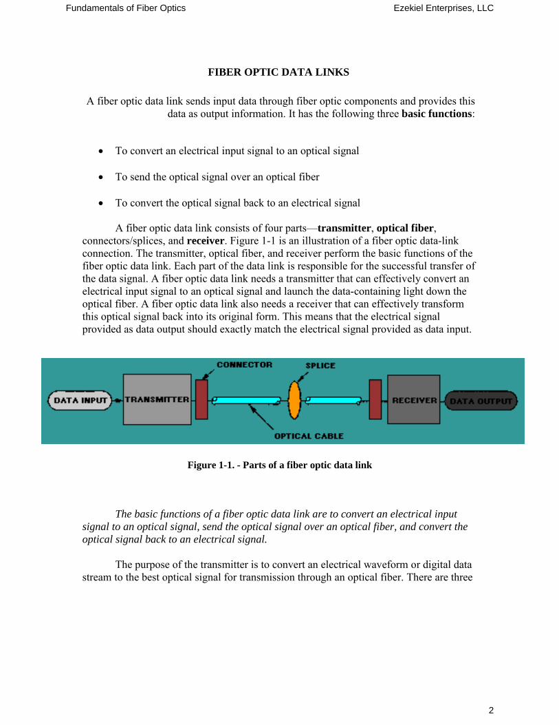
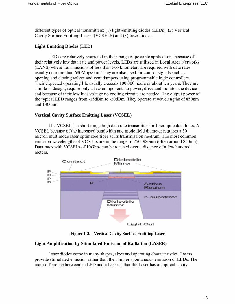
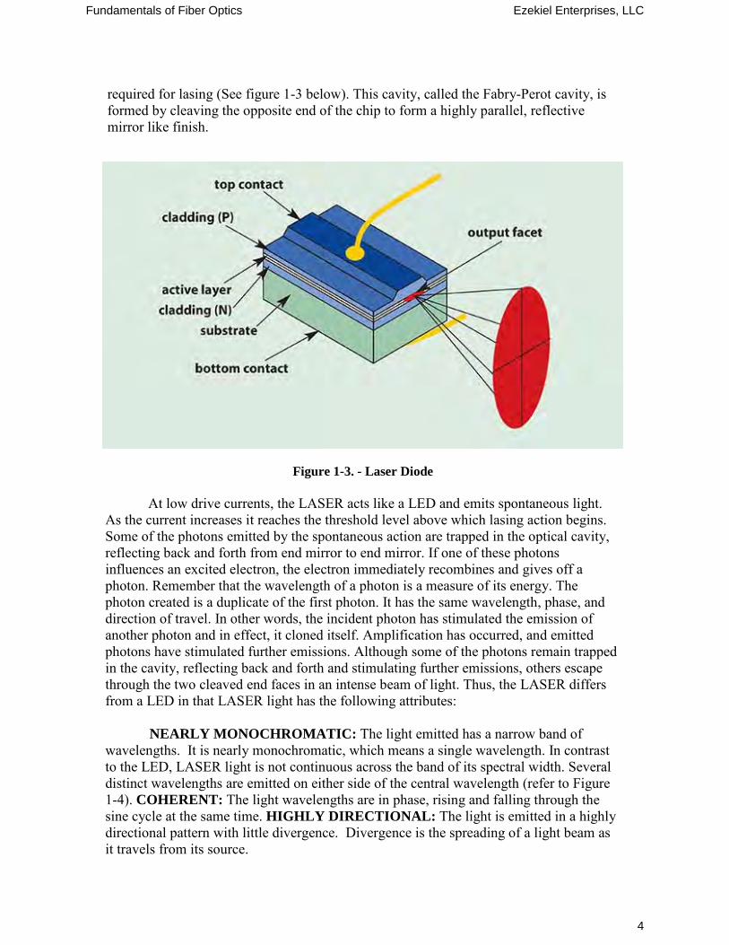
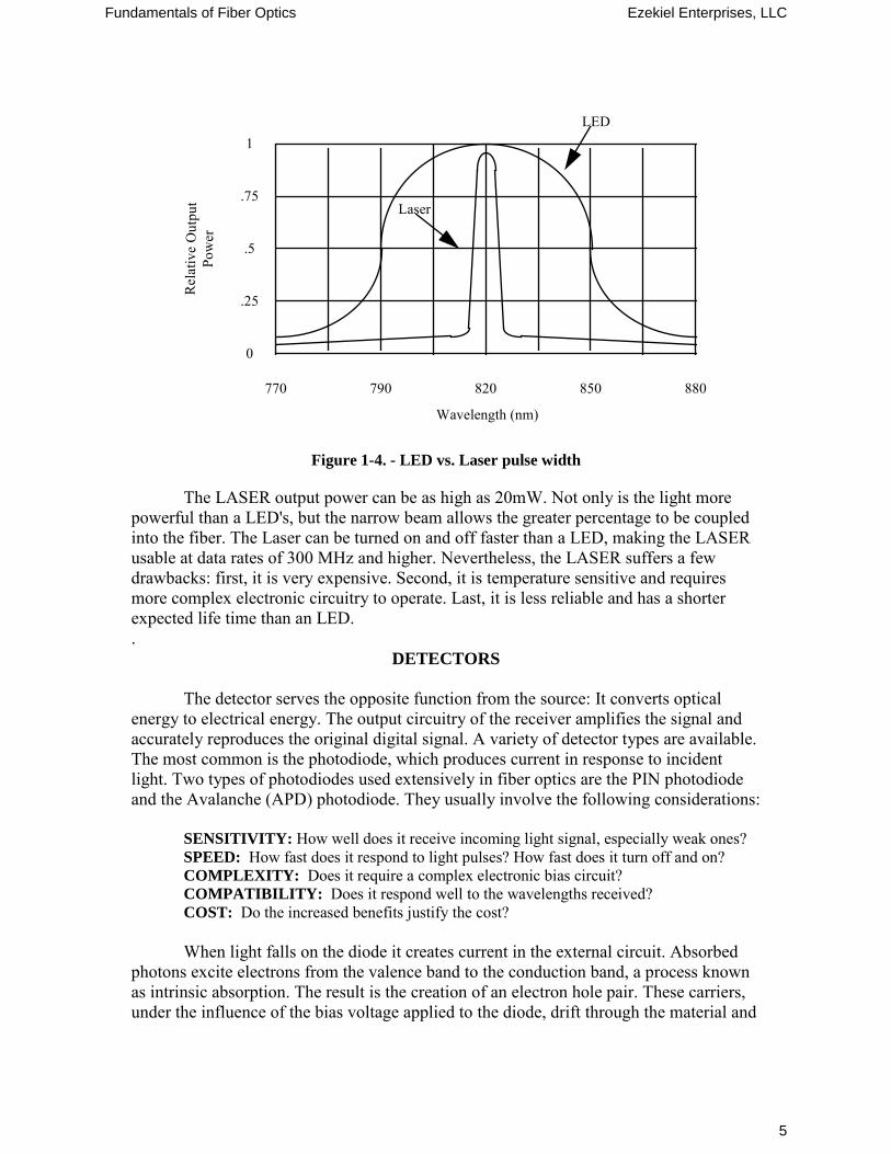
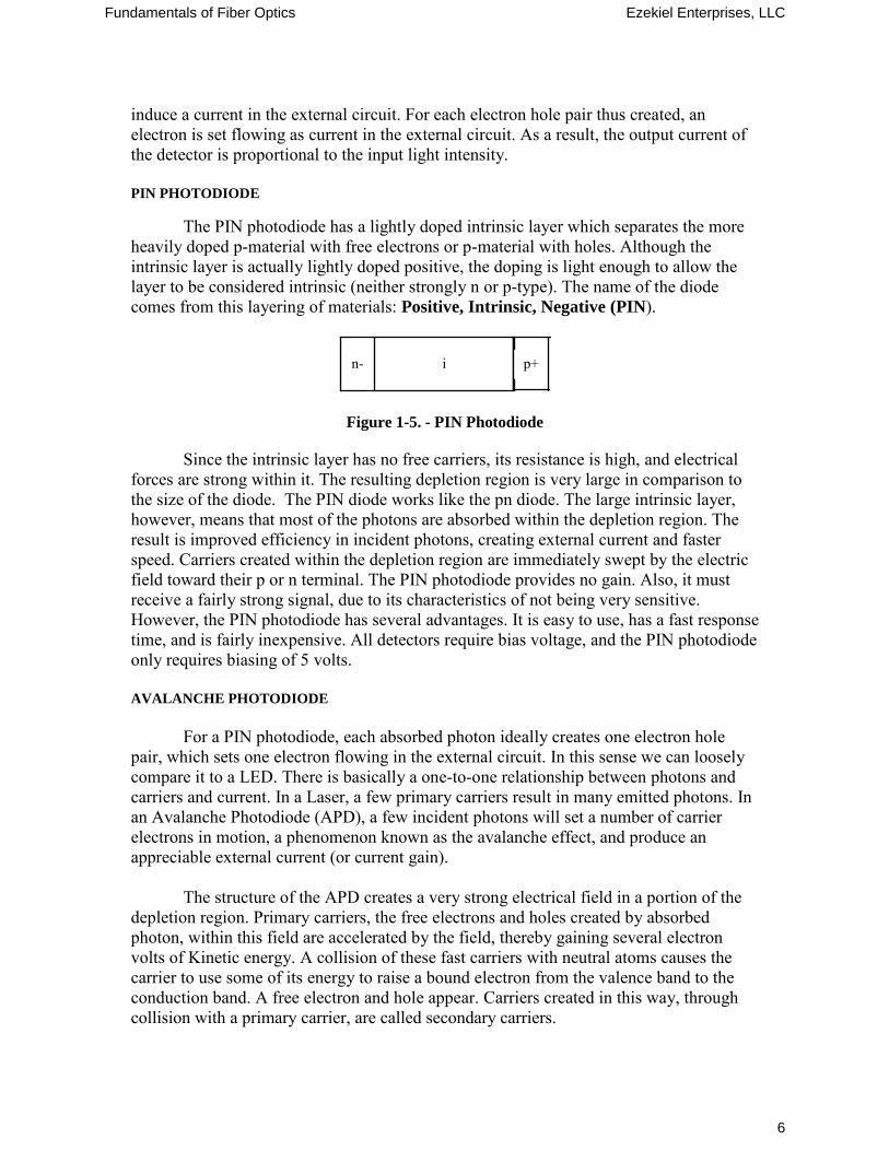
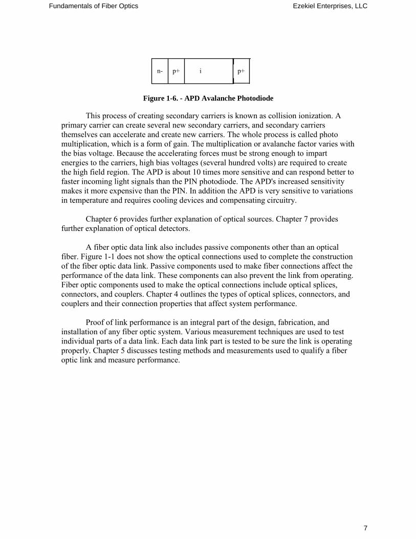
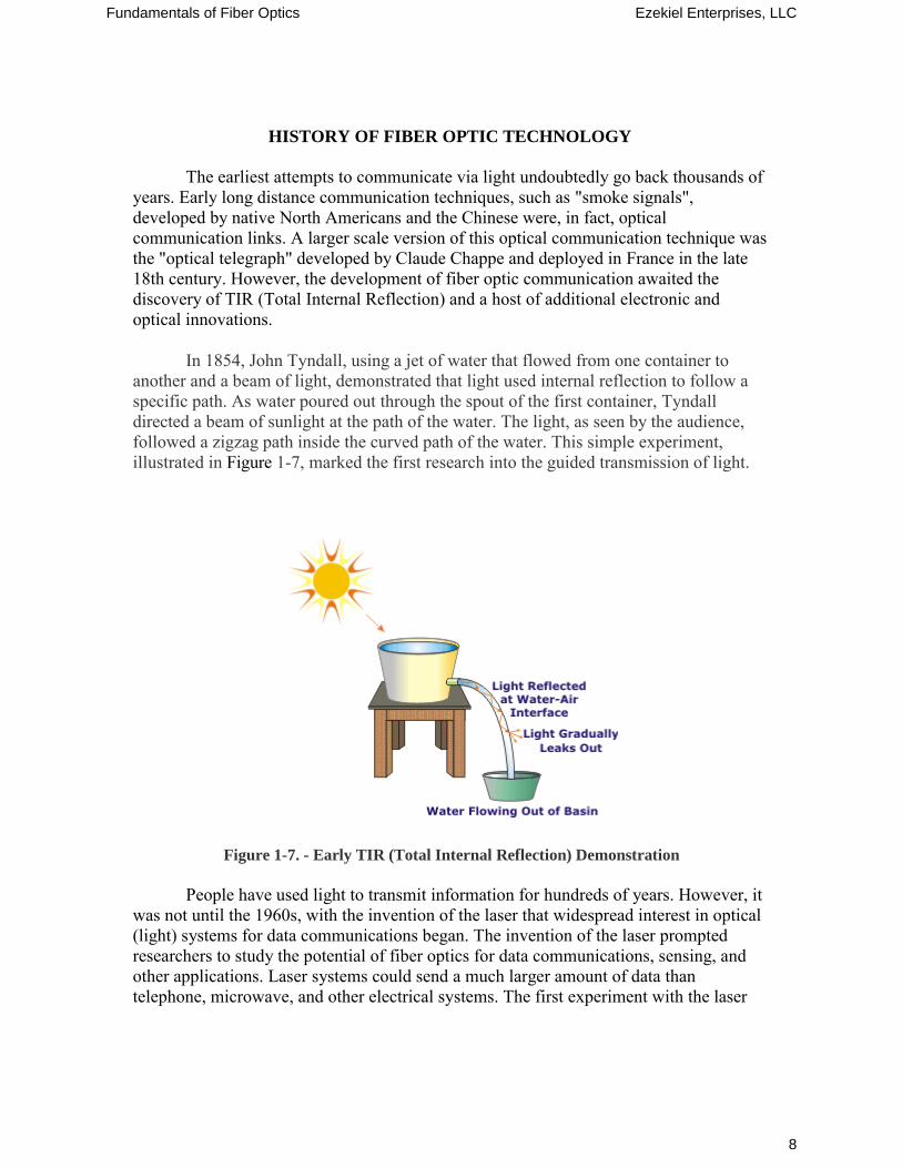
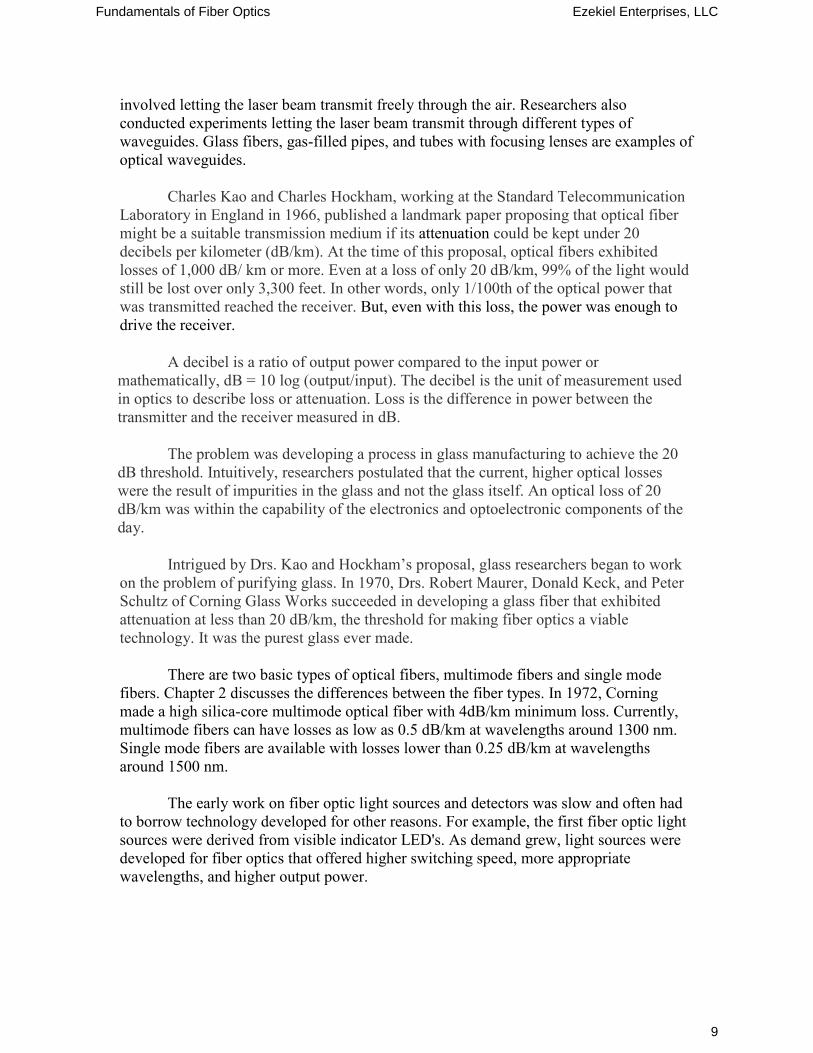
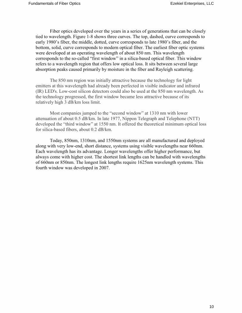
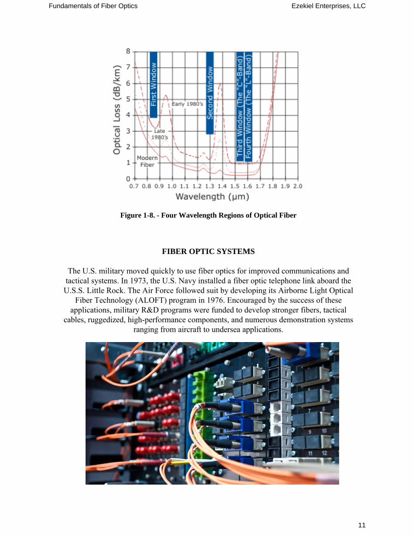
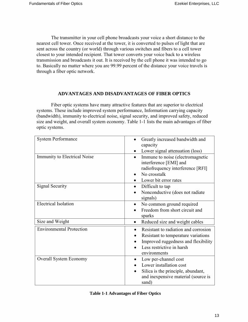
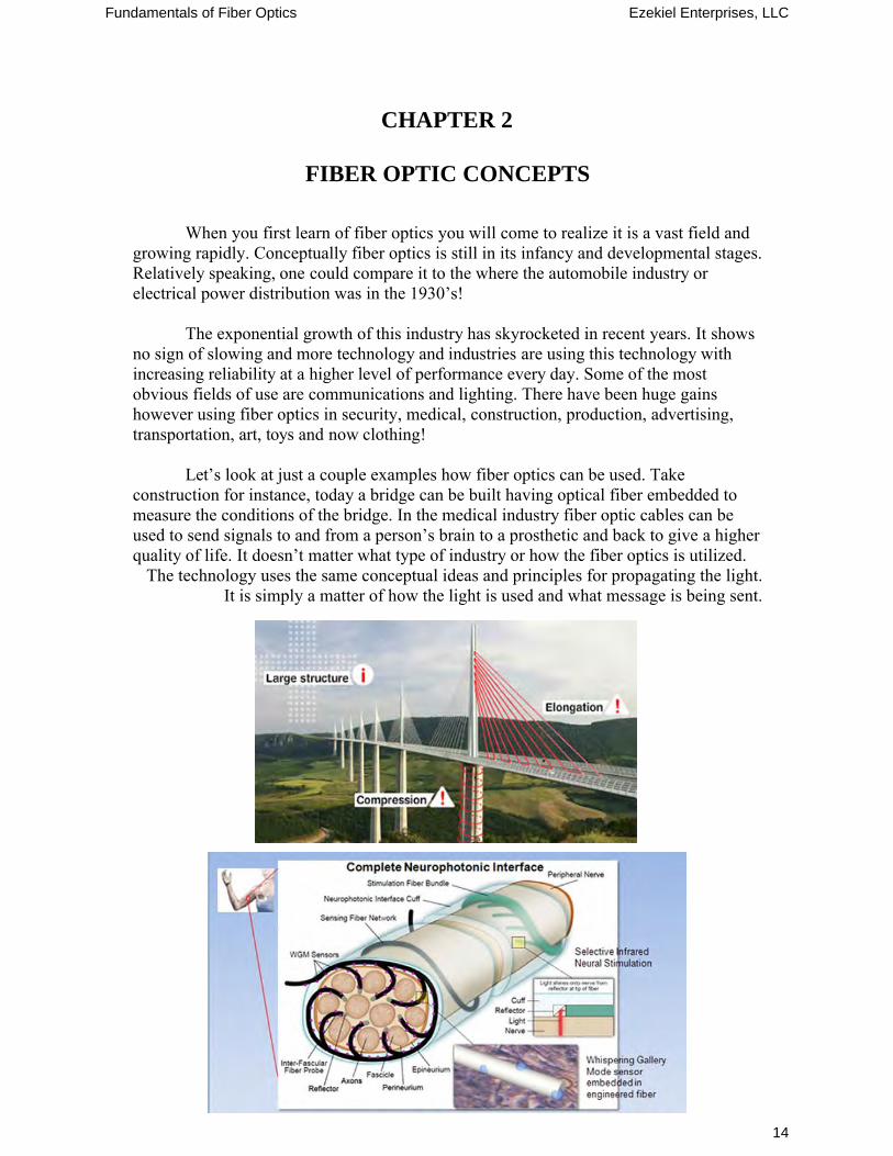
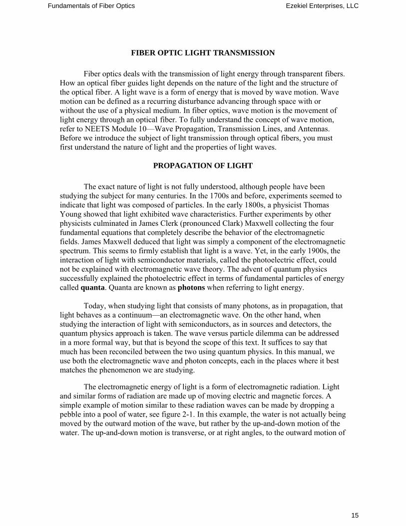
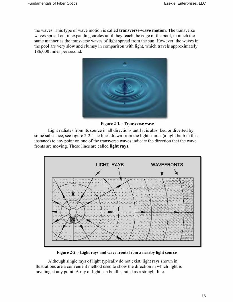
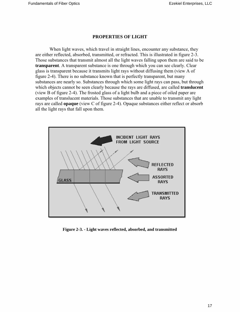
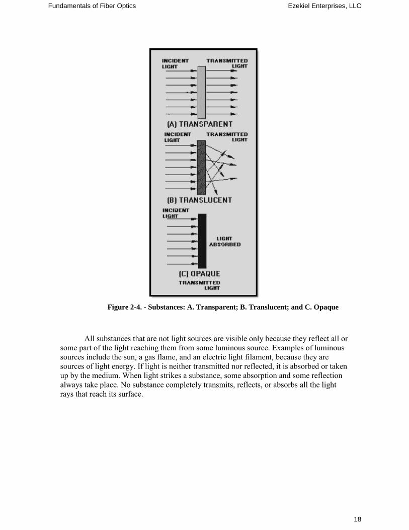
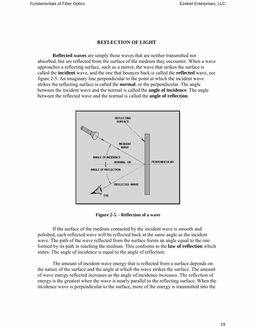
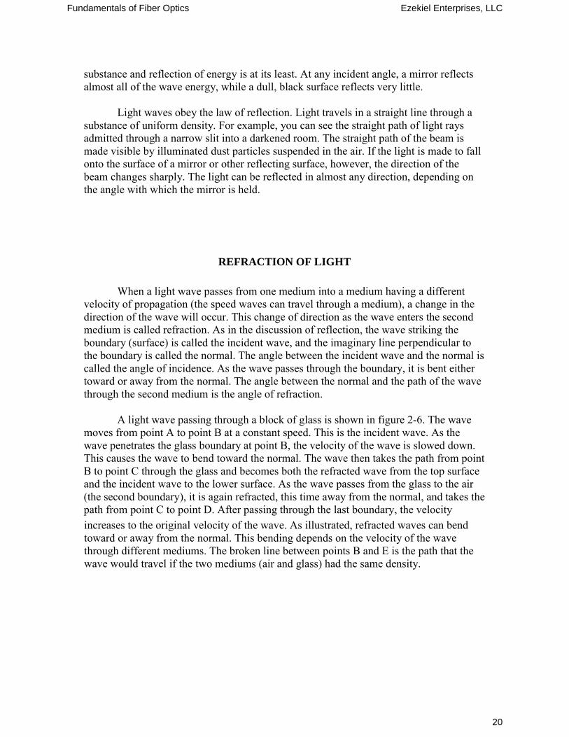
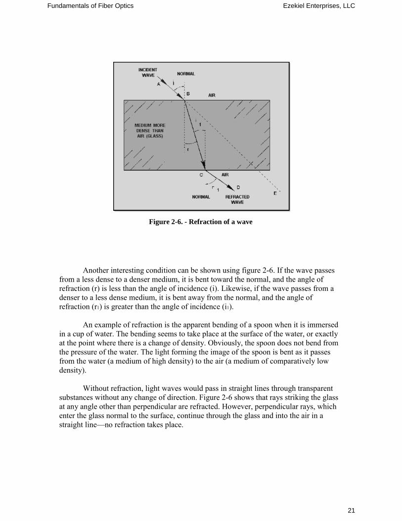
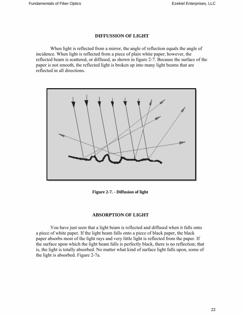
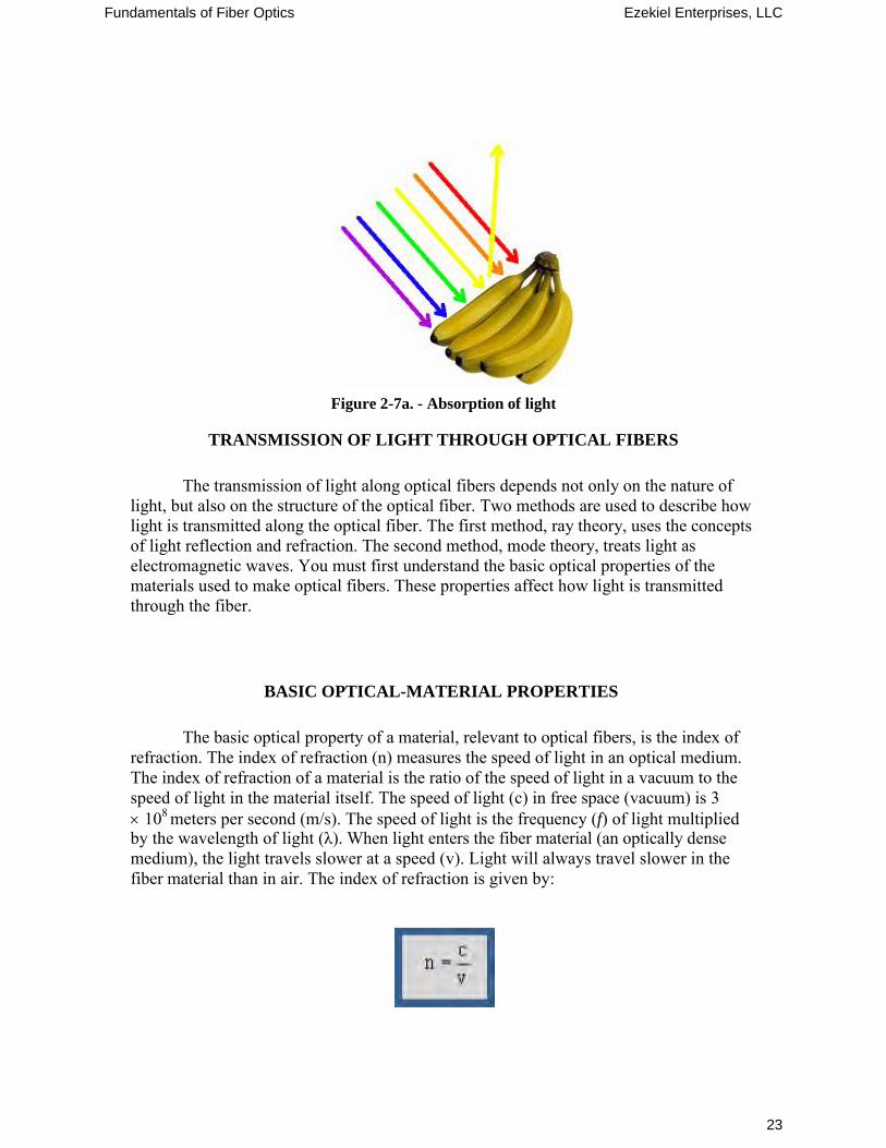
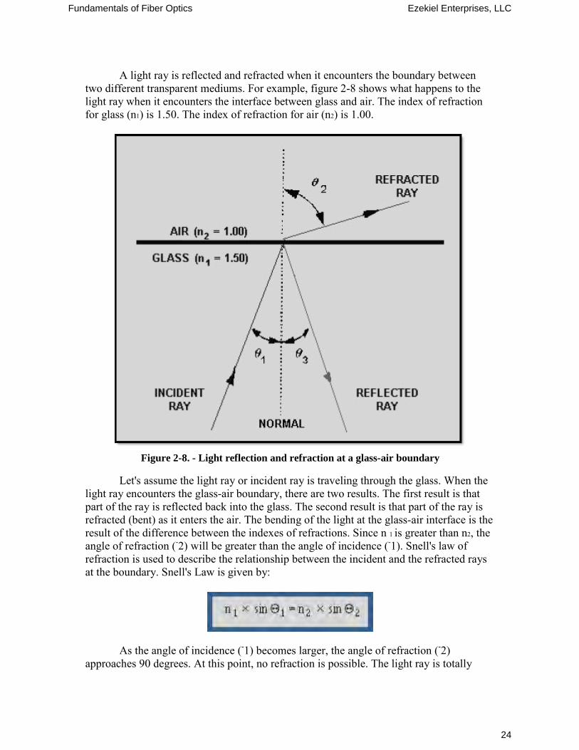
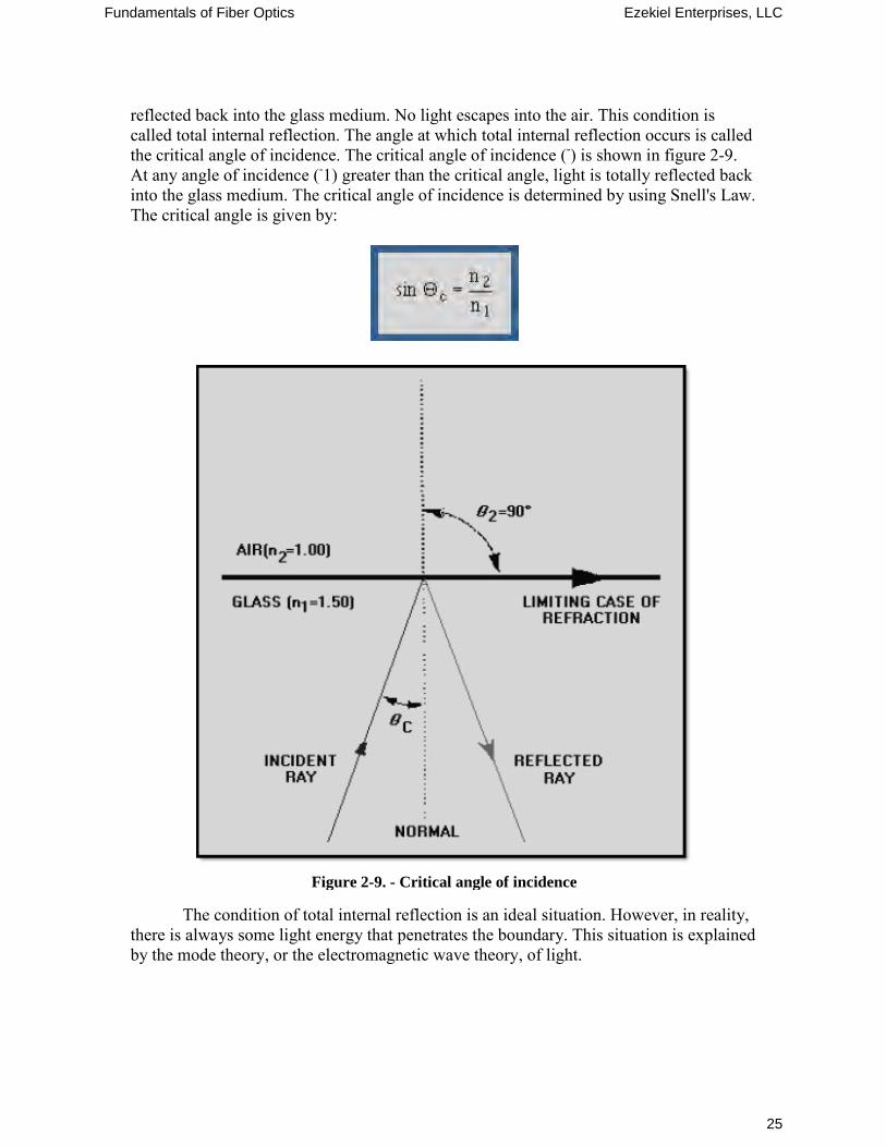
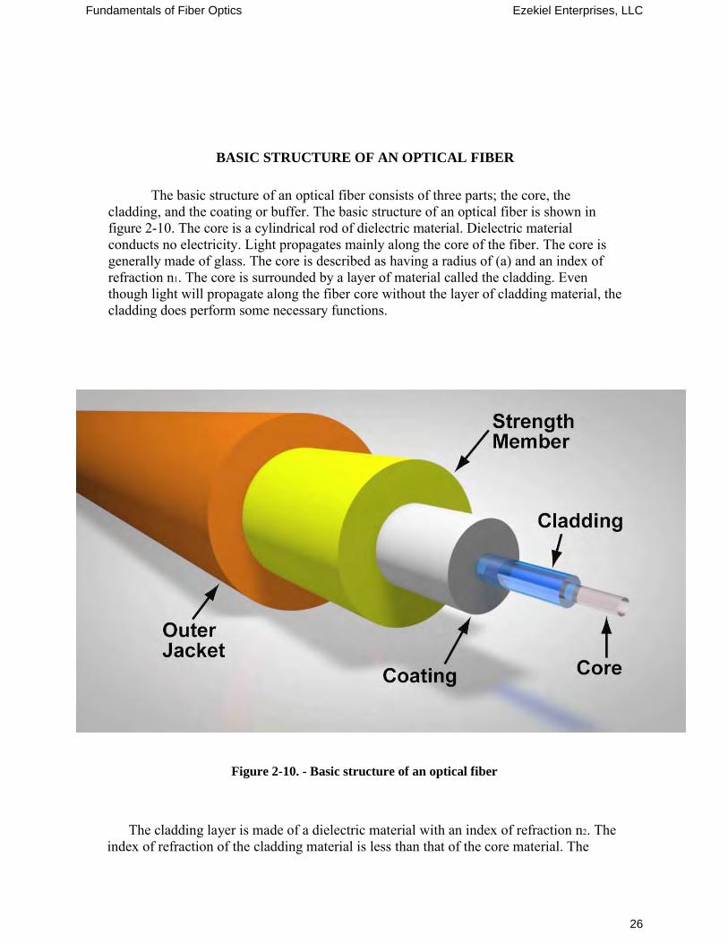
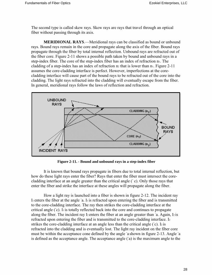
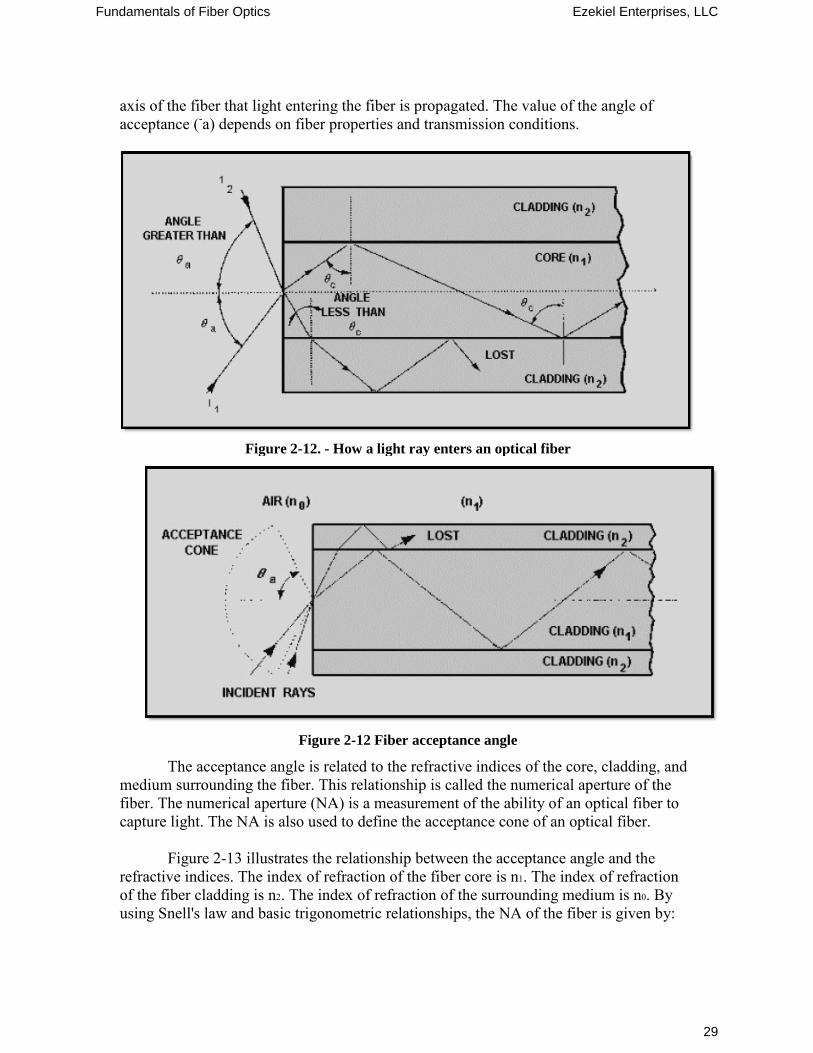
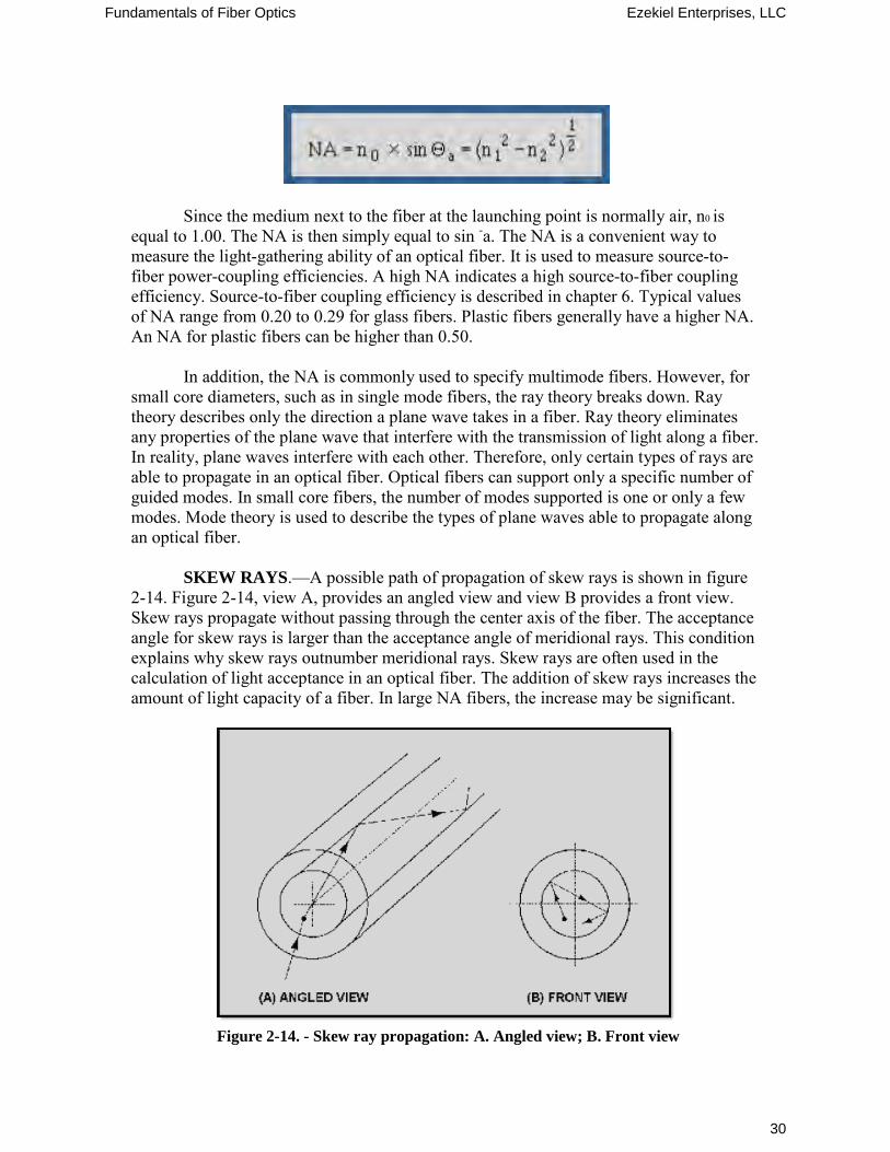
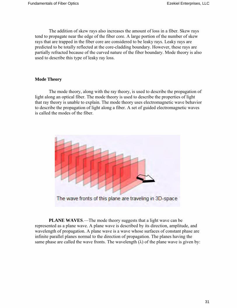
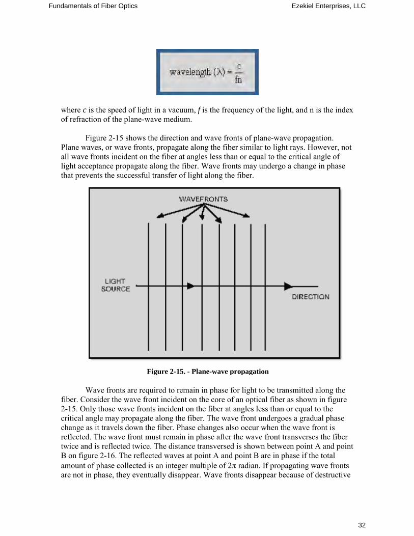
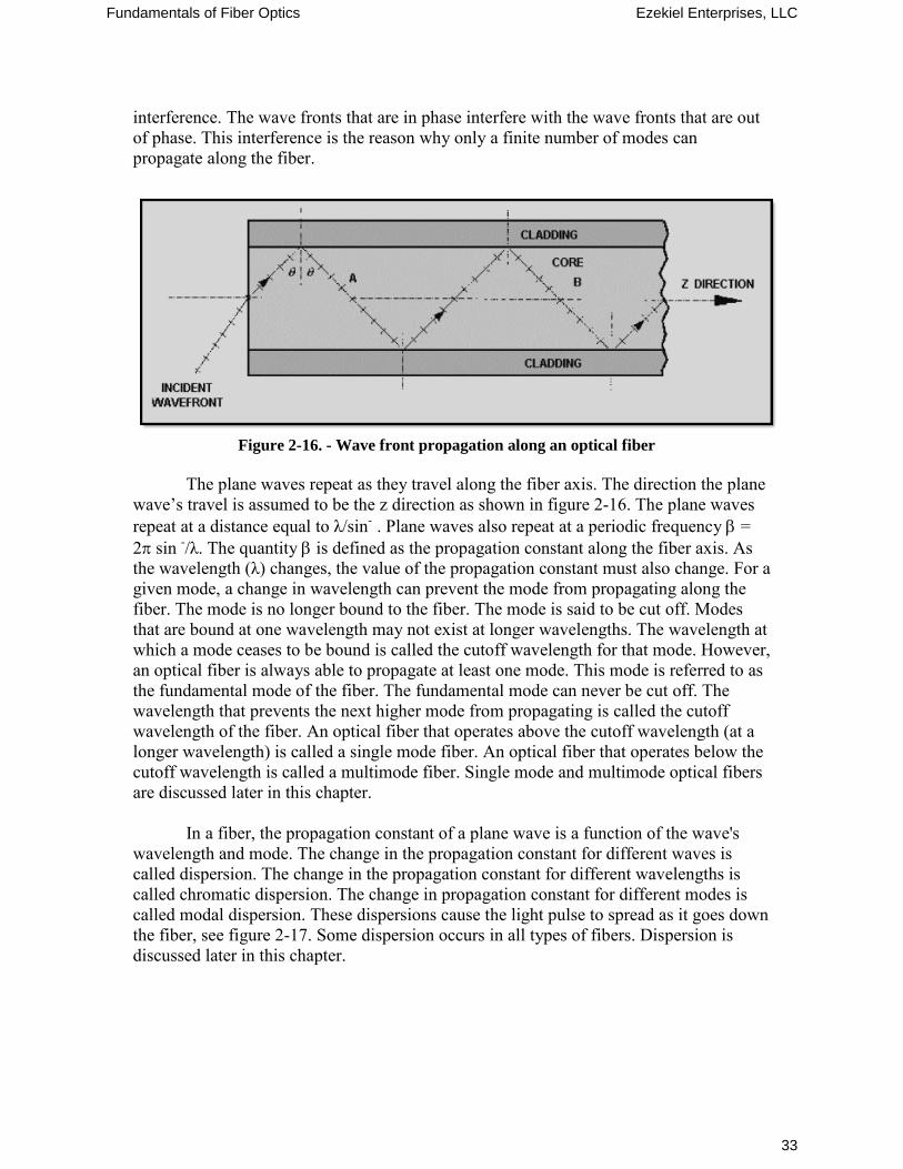
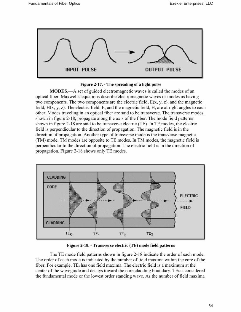
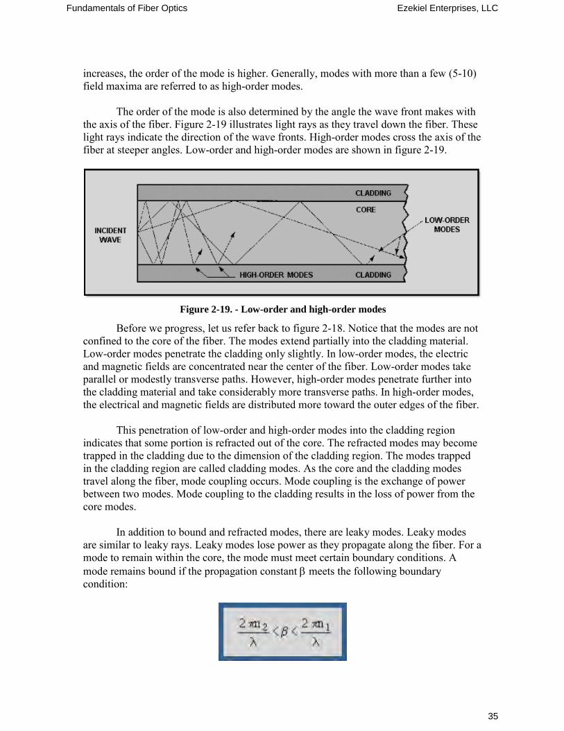
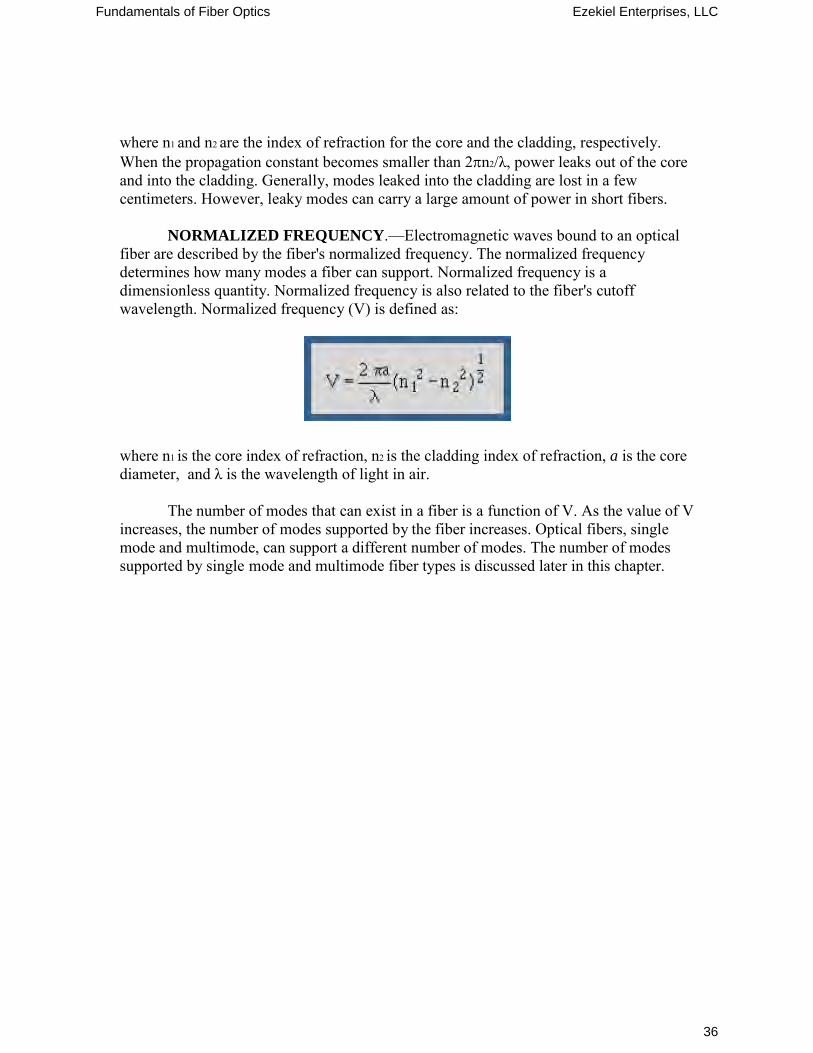
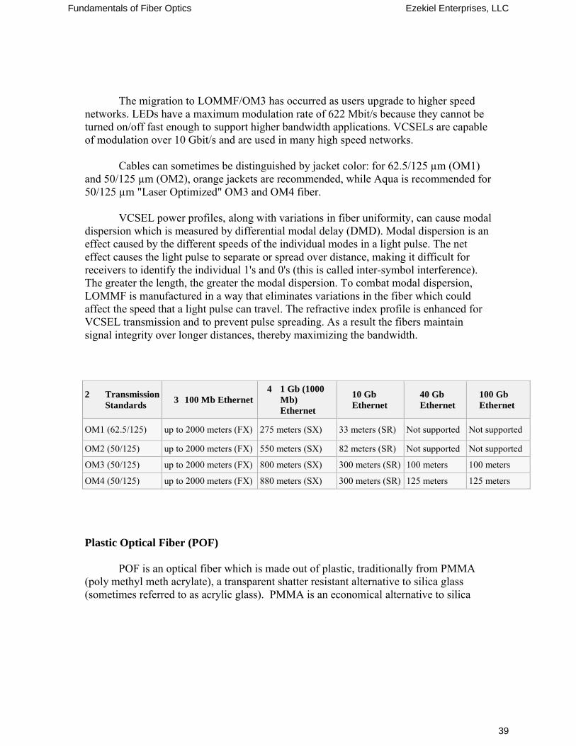
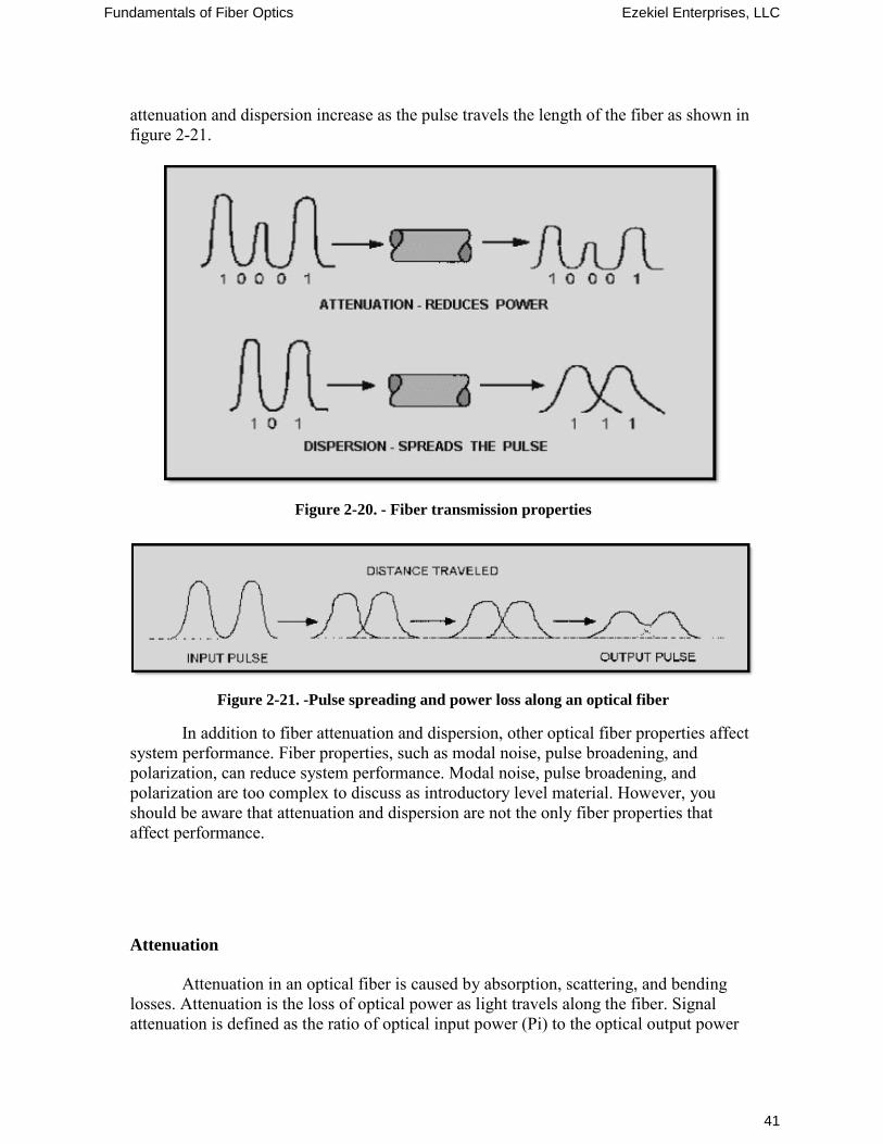
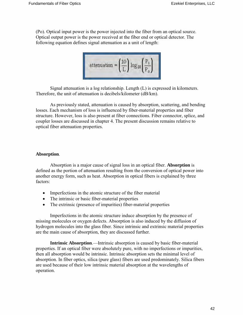
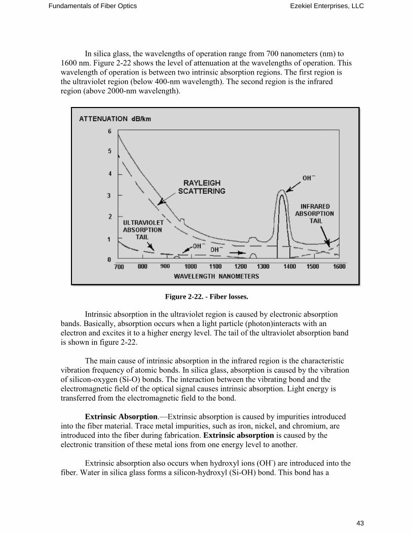
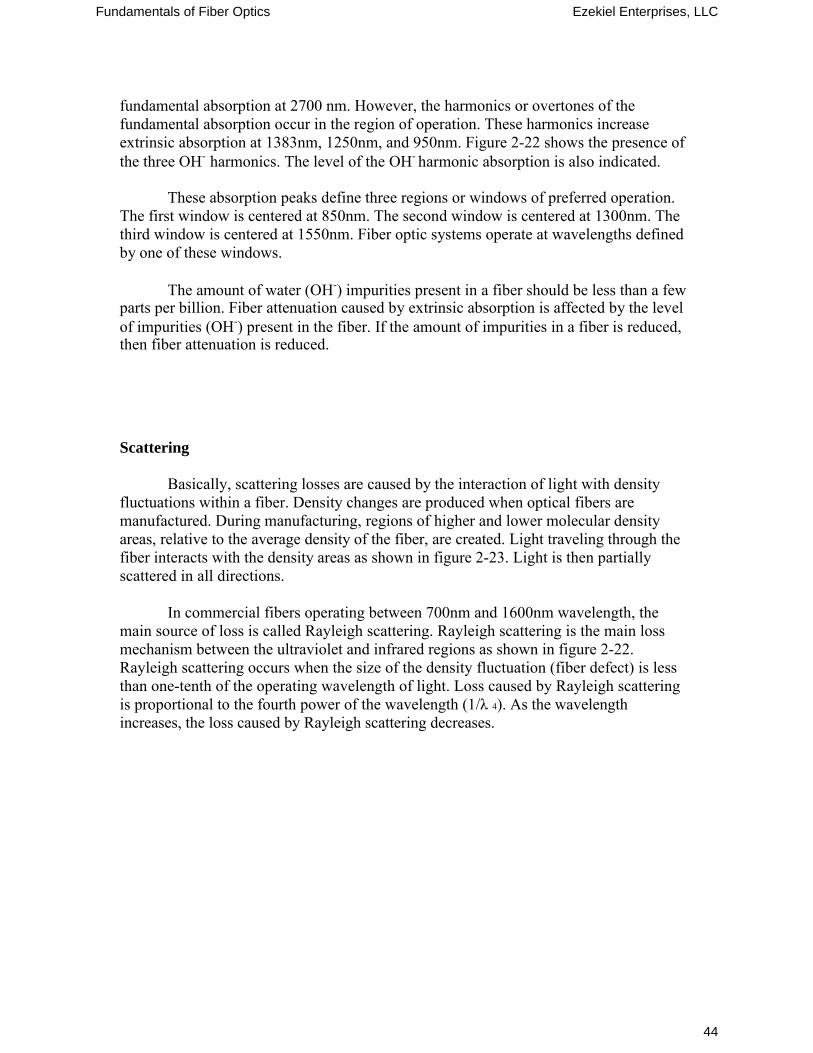
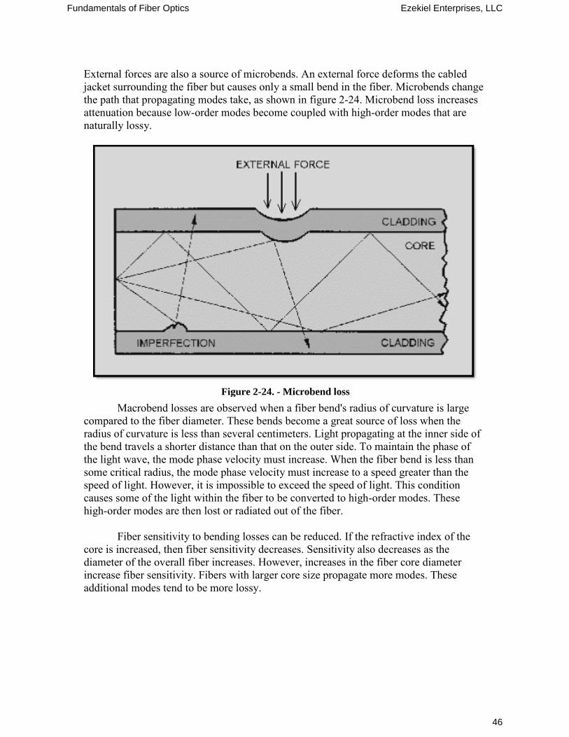
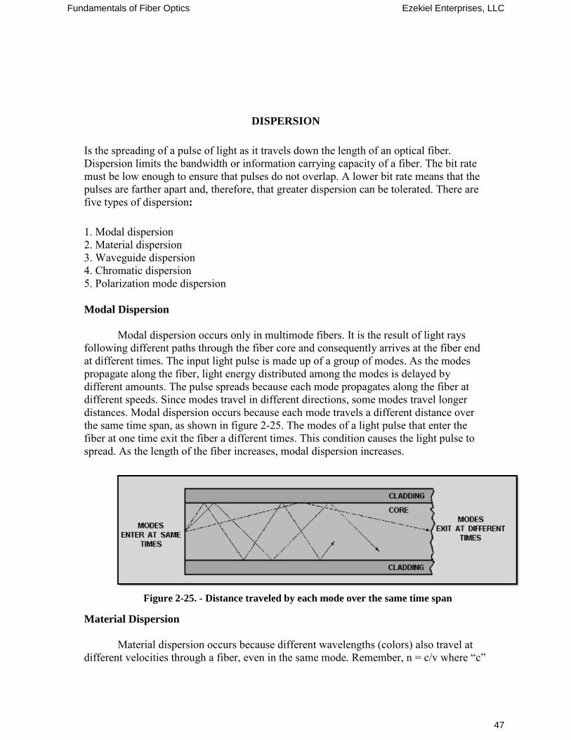
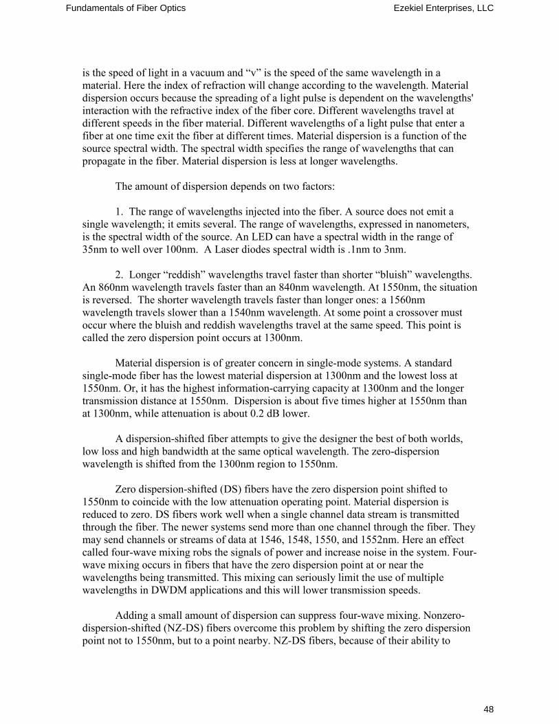
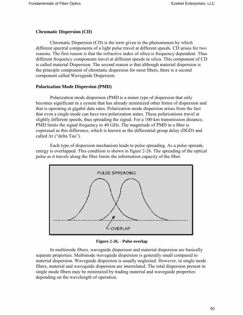
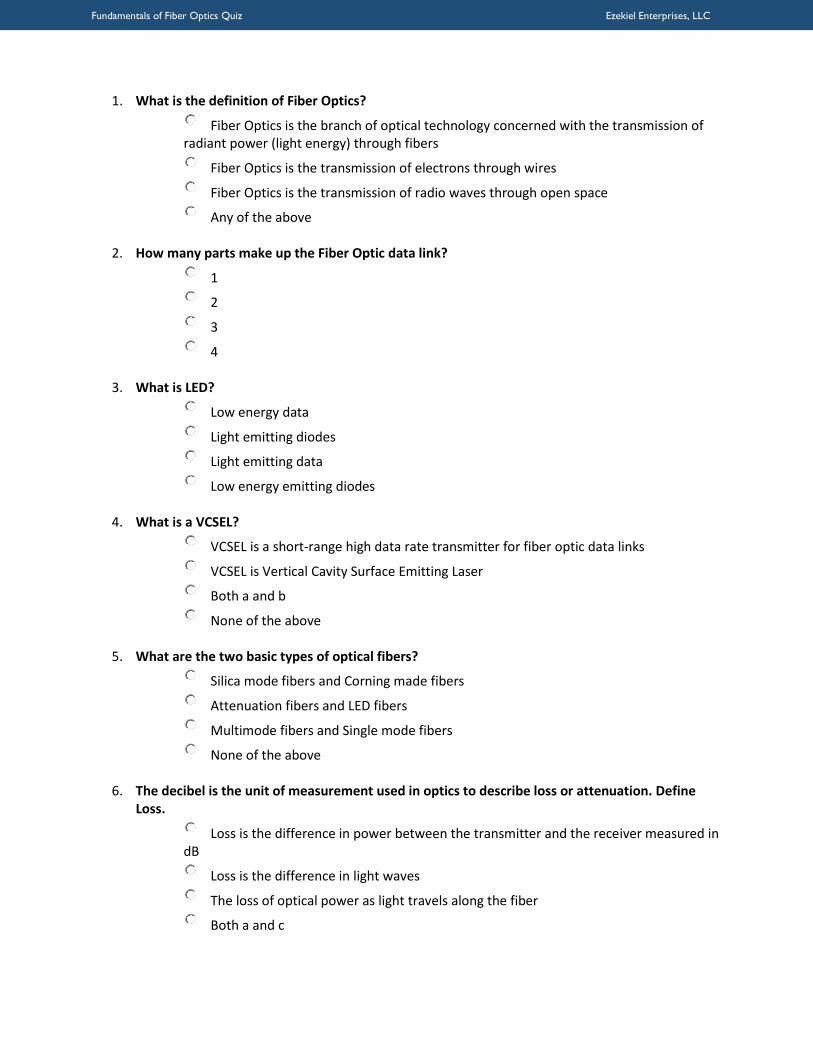
Fundamentals of Fiber Optics Quiz Ezekiel Enterprises LLC
7 What is the definition of Lightwave
o Lightwave is a form of energy that is moved by wave motion
o Lightwave is a recurring disturbance advancing through space
o Lightwave is composed of tiny particles
o All of the above o
8 Reflected light waves obey what law
o No laws
o Laws of reflection
o Snells law
o Faradays law o
9 What type of wave motion is represented by the motion of water
o Reflection wave motion
o Photon wave dispersion
o Refracted wave motion
o Transverse-wave motion o
10 Two methods describe how light propagates along an optical fiber These methods define two theories of light propagation What do we call these two theories
o The ray theory and the mode theory
o The wave theory and the reflection theory
o The Snell theory and the Faraday theory
o None of the above o
11 A light wave enters a sheet of glass at a perfect right angle to the surface Is the majority of the wave reflected refracted transmitted or absorbed
o Reflected
o Refracted
o Transmitted
o Absorbed o
12 What are Microbends
o Small microscopic bends of the fiber axis that occur mainly when a fiber is cabled
o Small beads that expand when water is added
o Small microscopic breaks of the fiber at points of high induced stress
o None of the above
Fundamentals of Fiber Optics Quiz Ezekiel Enterprises LLC
13 Why does Chromatic Dispersion occur
o It occurs when impurities such as hydroxyl ions (OH-) are introduced into the fiber
o It occurs because light travels through different materials and different waveguide structures at different speeds
o It occurs when meridional rays pass through the axis of the optical fiber
o None of the above o
14 What is the Acceptance Angle
o It is the maximum angle to the axis of the fiber that light entering the fiber is bound or propagated
o It is a measurement of the ability of an optical fiber to capture light
o The minimum incidence angle which is considered acceptable
o None of the above o
15 What does the Ray Theory describe
o It describes how light rays propagate along an optical fiber
o It describes how the fibers use electromagnetic wave behavior to describe the propagation of light along an optical fiber
o Describes the relationship between the incident and the refracted rays when light rays encounter the boundary between two different transparent materials
o None of the above
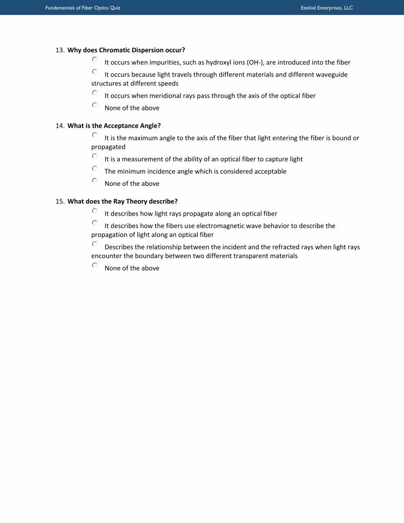
Fundamentals of Fiber Optics Quiz Ezekiel Enterprises LLC
13 Why does Chromatic Dispersion occur
o It occurs when impurities such as hydroxyl ions (OH-) are introduced into the fiber
o It occurs because light travels through different materials and different waveguide structures at different speeds
o It occurs when meridional rays pass through the axis of the optical fiber
o None of the above o
14 What is the Acceptance Angle
o It is the maximum angle to the axis of the fiber that light entering the fiber is bound or propagated
o It is a measurement of the ability of an optical fiber to capture light
o The minimum incidence angle which is considered acceptable
o None of the above o
15 What does the Ray Theory describe
o It describes how light rays propagate along an optical fiber
o It describes how the fibers use electromagnetic wave behavior to describe the propagation of light along an optical fiber
o Describes the relationship between the incident and the refracted rays when light rays encounter the boundary between two different transparent materials
o None of the above
Top Related