


Languages
Pages
Legal

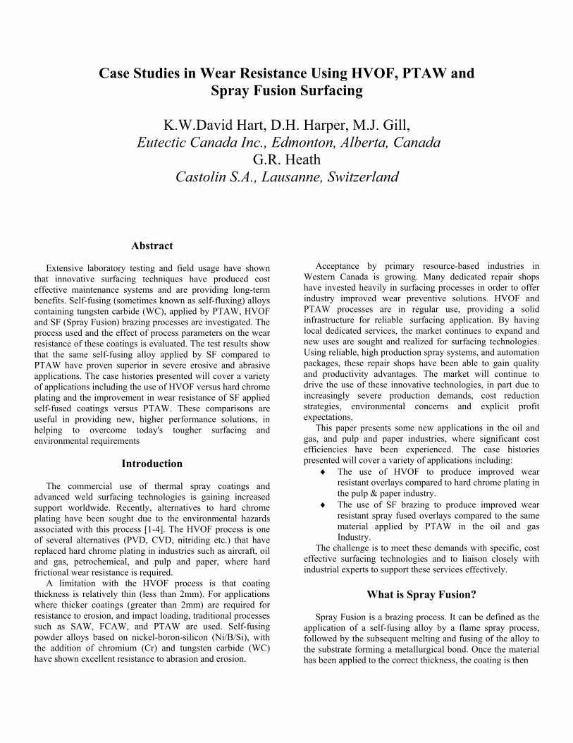
Case Studies in Wear Resistance Using HVOF, PTAW and Spray Fusion Surfacing
K.W.David Hart, D.H. Harper, M.J. Gill,
Eutectic Canada Inc., Edmonton, Alberta, Canada G.R. Heath
Castolin S.A., Lausanne, Switzerland
Abstract Acceptance by primary resource-based industries in Western Canada is growing. Many dedicated repair shops have invested heavily in surfacing processes in order to offer industry improved wear preventive solutions. HVOF and PTAW processes are in regular use, providing a solid infrastructure for reliable surfacing application. By having local dedicated services, the market continues to expand and new uses are sought and realized for surfacing technologies. Using reliable, high production spray systems, and automation packages, these repair shops have been able to gain quality and productivity advantages. The market will continue to drive the use of these innovative technologies, in part due to increasingly severe production demands, cost reduction strategies, environmental concerns and explicit profit expectations.
Extensive laboratory testing and field usage have shown that innovative surfacing techniques have produced cost effective maintenance systems and are providing long-term benefits. Self-fusing (sometimes known as self-fluxing) alloys containing tungsten carbide (WC), applied by PTAW, HVOF and SF (Spray Fusion) brazing processes are investigated. The process used and the effect of process parameters on the wear resistance of these coatings is evaluated. The test results show that the same self-fusing alloy applied by SF compared to PTAW have proven superior in severe erosive and abrasive applications. The case histories presented will cover a variety of applications including the use of HVOF versus hard chrome plating and the improvement in wear resistance of SF applied self-fused coatings versus PTAW. These comparisons are useful in providing new, higher performance solutions, in helping to overcome today's tougher surfacing and environmental requirements
This paper presents some new applications in the oil and gas, and pulp and paper industries, where significant cost efficiencies have been experienced. The case histories presented will cover a variety of applications including:
Introduction
♦ The use of HVOF to produce improved wear resistant overlays compared to hard chrome plating in the pulp & paper industry.
The commercial use of thermal spray coatings and advanced weld surfacing technologies is gaining increased support worldwide. Recently, alternatives to hard chrome plating have been sought due to the environmental hazards associated with this process [1-4]. The HVOF process is one of several alternatives (PVD, CVD, nitriding etc.) that have replaced hard chrome plating in industries such as aircraft, oil and gas, petrochemical, and pulp and paper, where hard frictional wear resistance is required.
♦ The use of SF brazing to produce improved wear resistant spray fused overlays compared to the same material applied by PTAW in the oil and gas Industry.
The challenge is to meet these demands with specific, cost effective surfacing technologies and to liaison closely with industrial experts to support these services effectively. A limitation with the HVOF process is that coating
thickness is relatively thin (less than 2mm). For applications where thicker coatings (greater than 2mm) are required for resistance to erosion, and impact loading, traditional processes such as SAW, FCAW, and PTAW are used. Self-fusing powder alloys based on nickel-boron-silicon (Ni/B/Si), with the addition of chromium (Cr) and tungsten carbide (WC) have shown excellent resistance to abrasion and erosion.
What is Spray Fusion? Spray Fusion is a brazing process. It can be defined as the application of a self-fusing alloy by a flame spray process, followed by the subsequent melting and fusing of the alloy to the substrate forming a metallurgical bond. Once the material has been applied to the correct thickness, the coating is then
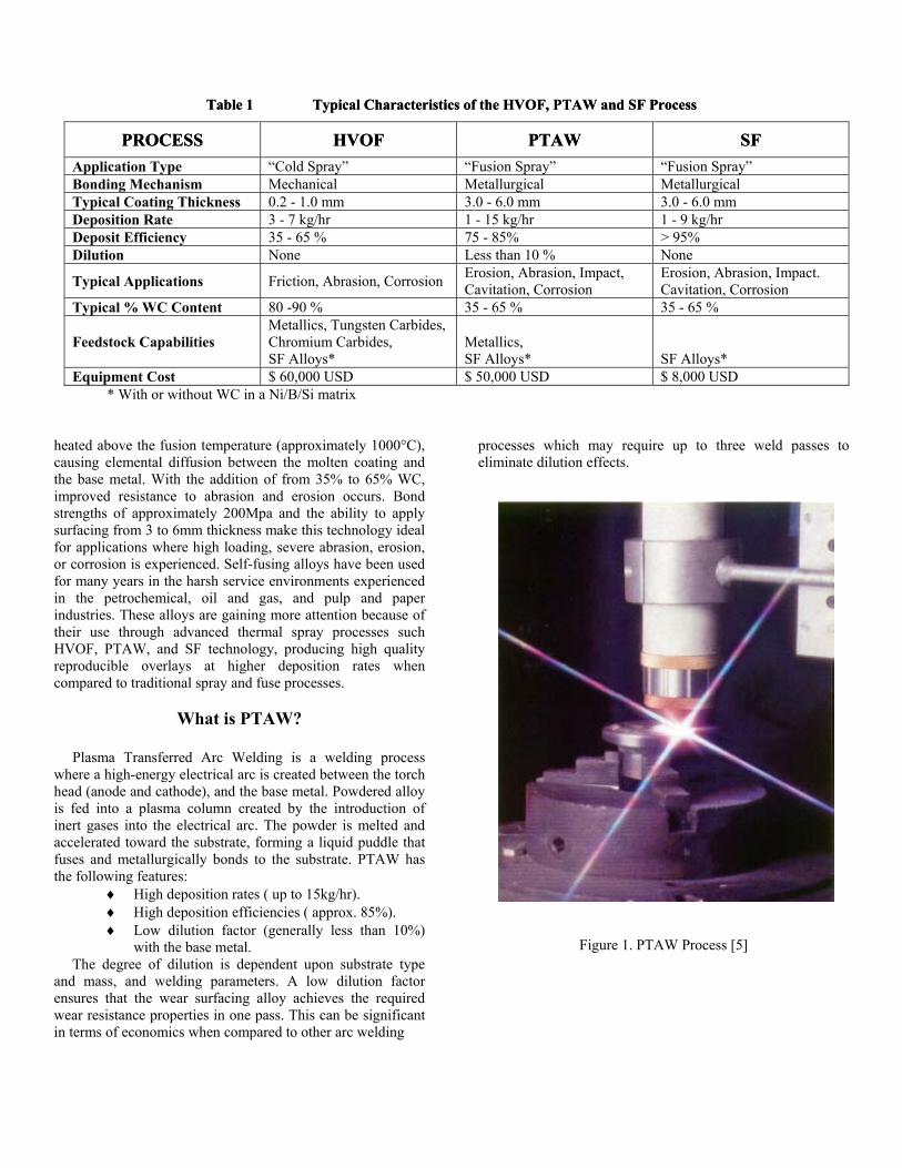
Table 1 Typical Characteristics of the HVOF, PTAW and SF Process Table 1 Typical Characteristics of the HVOF, PTAW and SF Process
PROCESS PROCESS HVOF HVOF PTAW PTAW SF SF Application Type “Cold Spray” “Fusion Spray” “Fusion Spray” Bonding Mechanism Mechanical Metallurgical Metallurgical Typical Coating Thickness 0.2 - 1.0 mm 3.0 - 6.0 mm 3.0 - 6.0 mm Deposition Rate 3 - 7 kg/hr 1 - 15 kg/hr 1 - 9 kg/hr Deposit Efficiency 35 - 65 % 75 - 85% > 95% Dilution None Less than 10 % None
Typical Applications Friction, Abrasion, Corrosion Erosion, Abrasion, Impact, Cavitation, Corrosion
Erosion, Abrasion, Impact. Cavitation, Corrosion
Typical % WC Content 80 -90 % 35 - 65 % 35 - 65 %
Feedstock Capabilities Metallics, Tungsten Carbides, Chromium Carbides, SF Alloys*
Metallics, SF Alloys*
SF Alloys*
Equipment Cost $ 60,000 USD $ 50,000 USD $ 8,000 USD * With or without WC in a Ni/B/Si matrix heated above the fusion temperature (approximately 1000°C), causing elemental diffusion between the molten coating and the base metal. With the addition of from 35% to 65% WC, improved resistance to abrasion and erosion occurs. Bond strengths of approximately 200Mpa and the ability to apply surfacing from 3 to 6mm thickness make this technology ideal for applications where high loading, severe abrasion, erosion, or corrosion is experienced. Self-fusing alloys have been used for many years in the harsh service environments experienced in the petrochemical, oil and gas, and pulp and paper industries. These alloys are gaining more attention because of their use through advanced thermal spray processes such HVOF, PTAW, and SF technology, producing high quality reproducible overlays at higher deposition rates when compared to traditional spray and fuse processes.
processes which may require up to three weld passes to eliminate dilution effects.
What is PTAW?
Plasma Transferred Arc Welding is a welding process where a high-energy electrical arc is created between the torch head (anode and cathode), and the base metal. Powdered alloy is fed into a plasma column created by the introduction of inert gases into the electrical arc. The powder is melted and accelerated toward the substrate, forming a liquid puddle that fuses and metallurgically bonds to the substrate. PTAW has the following features:
♦ High deposition rates ( up to 15kg/hr). ♦ High deposition efficiencies ( approx. 85%). ♦ Low dilution factor (generally less than 10%)
with the base metal. Figure 1. PTAW Process [5] The degree of dilution is dependent upon substrate type
and mass, and welding parameters. A low dilution factor ensures that the wear surfacing alloy achieves the required wear resistance properties in one pass. This can be significant in terms of economics when compared to other arc welding
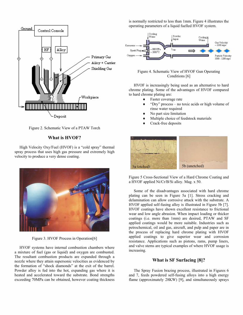
Figure 2. Schematic View of a PTAW Torch
What is HVOF?
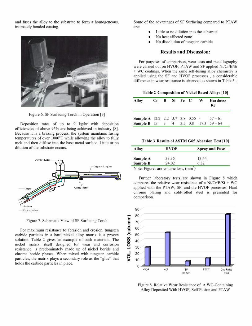
High Velocity Oxy/Fuel (HVOF) is a “cold spray” thermal spray process that uses high gas pressure and extremely high velocity to produce a very dense coating.
Figure 3. HVOF Process in Operation[6]
HVOF systems have internal combustion chambers where a mixture of fuel (gas or liquid) and oxygen are combusted. The resultant combustion products are expanded through a nozzle where they attain supersonic velocities as evidenced by the formation of “shock diamonds” at the exit of the barrel. Powder alloy is fed into the hot, expanding gas where it is heated and accelerated toward the substrate. Bond strengths exceeding 70MPa can be obtained, however coating thickness
is normally restricted to less than 1mm. Figure 4 illustrates the operating parameters of a liquid fuelled HVOF system.
Figure 4. Schematic View of HVOF Gun Operating
Conditions [6] HVOF is increasingly being used as an alternative to hard chrome plating. Some of the advantages of HVOF compared to hard chrome plating are:
♦ Faster coverage rate ♦ “Dry” process – no toxic acids or high volume of
rinse water required ♦ No part size limitation ♦ Multiple choice of feedstock materials ♦ Crack-free deposits
5b (unetched) 5a (etched) Figure 5 Cross-Sectional View of a Hard Chrome Coating and a HVOF applied Ni/Cr/B/Si alloy. Mag. x 50. Some of the disadvantages associated with hard chrome plating can be seen in Figure 5a [1]. Stress cracking and delamination can allow corrosive attack with the substrate. A HVOF applied self-fusing alloy is illustrated in Figure 5b [7]. HVOF coatings have shown excellent resistance to frictional wear and low angle abrasion. When impact loading or thicker coatings (i.e. more than 1mm) are desired, PTAW and SF applied coatings would be more suitable. Industries such as petrochemical, oil and gas, aircraft, and pulp and paper are in the process of replacing hard chrome plating with HVOF applied coatings to give superior wear and corrosion resistance. Applications such as pistons, rams, pump liners, and valve stems are typical examples of where HVOF usage is increasing.
What is SF Surfacing [8]? The Spray Fusion brazing process, illustrated in Figures 6 and 7, feeds powdered self-fusing alloys into a high energy flame (approximately 28KW) [9], and simultaneously sprays
and fuses the alloy to the substrate to form a homogeneous, intimately bonded coating.
Some of the advantages of SF Surfacing compared to PTAW are:
♦ Little or no dilution into the substrate ♦ No heat affected zone ♦ No dissolution of tungsten carbide
Results and Discussion:
For purposes of comparison, wear tests and metallography were carried out on HVOF, PTAW and SF applied Ni/Cr/B/Si + WC coatings. When the same self-fusing alloy chemistry is applied using the SF and HVOF processes , a considerable difference in wear resistance is observed as shown in Table 3 .
Table 2 Composition of Nickel Based Alloys [10]
Alloy Cr B Si Fe C W Hardness Rc
Sample A 12.2 2.2 3.7 3.8 0.55 - 57 – 61 Sample B 15 3 4 3.5 0.8 17.3 59 – 64
Figure 6. SF Surfacing Torch in Operation [9]
Deposition rates of up to 9 kg/hr with deposition efficiencies of above 95% are being achieved in industry [8]. Because it is a brazing process, the system maintains fusing temperatures of over 1000oC while allowing the alloy to fully melt and then diffuse into the base metal surface. Little or no dilution of the substrate occurs.
Table 3 Results of ASTM G65 Abrasion Test [10]
Alloy HVOF Spray and Fuse Sample A 33.35 13.44 Sample B 24.02 6.32
Note: Figures are volume loss, (mm3) Further laboratory tests are shown in Figure 8 which compares the relative wear resistance of a Ni/Cr/B/Si + WC applied with the PTAW, SF, and the HVOF processes. Hard chrome plating and cold-rolled steel is presented for comparison.
01020
304050607080
90
VOL.
LO
SS (c
ub.m
m)
HVOF HCP SFBRAZE
PTAW Cold-RolledSteel
Figure 7. Schematic View of SF Surfacing Torch
For maximum resistance to abrasion and erosion, tungsten carbide particles in a hard nickel alloy matrix is a proven solution. Table 2 gives an example of such materials. The nickel matrix, itself designed for wear and corrosion resistance, is predominately made up of nickel boride and chrome boride phases. When mixed with tungsten carbide particles, the matrix plays a secondary role as the “glue” that holds the carbide particles in place.
Figure 8. Relative Wear Resistance of A WC-Containing Alloy Deposited With HVOF, Self Fusion and PTAW
Metallography was carried out to evaluate the effect of PTAW and SF application process parameters on the carbide shape and dilution.
INCREASING AMPERAGE
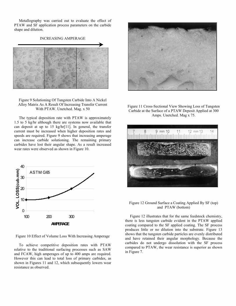
Figure 9 Solutioning Of Tungsten Carbide Into A Nickel Alloy Matrix As A Result Of Increasing Transfer Current
With PTAW. Unetched. Mag. x 50
Figure 11 Cross-Sectional View Showing Loss of Tungsten Carbide at the Surface of a PTAW Deposit Applied at 300
Amps. Unetched. Mag x 75. The typical deposition rate with PTAW is approximately 1.5 to 5 kg/hr although there are systems now available that can deposit at up to 15 kg/hr[11]. In general, the transfer current must be increased when higher deposition rates and speeds are required. Figure 9 shows that increasing amperage can increase carbide solutioning. The remaining primary carbides have lost their angular shape. As a result increased wear rates were observed as shown in Figure 10.
0
10
20
30
40
100 200 300
AMPERAGE
VOL.
LO
SS(c
ub.m
m)
A S T M G 65
Figure 12 Ground Surface a Coating Applied By SF (top) and PTAW (bottom)
Figure 12 illustrates that for the same feedstock chemistry, there is less tungsten carbide evident in the PTAW applied coating compared to the SF applied coating. The SF process produces little or no dilution into the substrate. Figure 13 shows that the tungsten carbide particles are evenly distributed and have retained their angular morphology. Because the carbides do not undergo dissolution with the SF process compared to PTAW, the wear resistance is superior as shown in Figure 7.
Figure 10 Effect of Volume Loss With Increasing Amperage To achieve competitive deposition rates with PTAW relative to the traditional surfacing processes such as SAW and FCAW, high amperages of up to 400 amps are required. However this can lead to total loss of primary carbides, as shown in Figures 11 and 12, which subsequently lowers wear resistance as observed.
Case Histories Industry: Pulp and Paper Application: Slotted Screening Baskets Process: HVOF These baskets or cylinders are used for separating (screening) sand and gravel from the wood chips. The basket is machined from 316L stainless steel and normally chrome plated for wear and corrosion resistance (the chips are slightly acidic). The baskets have precision 0.254mm slots machined into the circumference to create openings for the washing solution and foreign matter to be extracted. Wear causes the basket slots to open and elongate, reducing the efficiency and performance of the screening process. The baskets are made in two sizes, with replacement costs of CDN $9000.00 and CDN $28,000.00 respectively. Life cycles vary by mill lasting between 6 months to 2 years. Generally they are considered unrepairable and are discarded after their useful life.
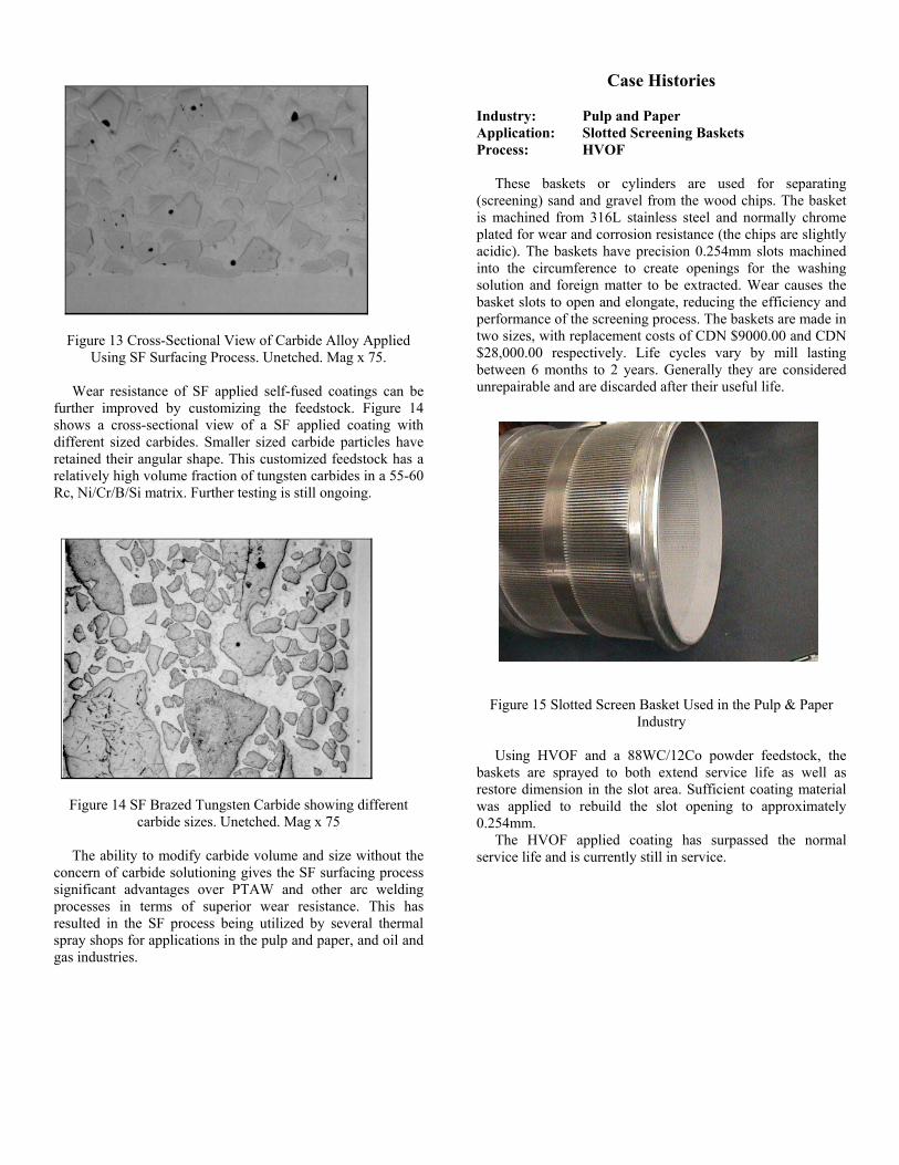
Figure 13 Cross-Sectional View of Carbide Alloy Applied
Using SF Surfacing Process. Unetched. Mag x 75. Wear resistance of SF applied self-fused coatings can be further improved by customizing the feedstock. Figure 14 shows a cross-sectional view of a SF applied coating with different sized carbides. Smaller sized carbide particles have retained their angular shape. This customized feedstock has a relatively high volume fraction of tungsten carbides in a 55-60 Rc, Ni/Cr/B/Si matrix. Further testing is still ongoing.
Figure 15 Slotted Screen Basket Used in the Pulp & Paper Industry
Using HVOF and a 88WC/12Co powder feedstock, the baskets are sprayed to both extend service life as well as restore dimension in the slot area. Sufficient coating material was applied to rebuild the slot opening to approximately 0.254mm.
Figure 14 SF Brazed Tungsten Carbide showing different
carbide sizes. Unetched. Mag x 75 The HVOF applied coating has surpassed the normal
service life and is currently still in service. The ability to modify carbide volume and size without the concern of carbide solutioning gives the SF surfacing process significant advantages over PTAW and other arc welding processes in terms of superior wear resistance. This has resulted in the SF process being utilized by several thermal spray shops for applications in the pulp and paper, and oil and gas industries.

Industry: Pulp and Paper Industry: Oil and Gas Application: Tertiary Knurled Sorter Rolls Application: Drill Stabilizers: Process: HVOF Process: SF Process
Wood chips enter via the chip in-feed deck to begin the sorting process. They enter the primary knurled sorter rolls and are fed along the top surface of the rolls. The chips that are of the right size or smaller, fall between the spaces between the rolls. The chips that are too big are carried across the surface and returned to the process for re-chipping.
Drill bit stabilization is used extensively in the drilling and exploration segment of the oil and gas industry. This is a leading application for SF surfacing technology, which has been successfully developed and installed in 3 countries.
Figure 16 SF Application on a Drill Stabilizer [9]
Figure 16 Tertiary Knurled Sorter Rolls The drill stabilizer allows the drill string to stay on-course and straight. The component is subjected to severe abrasion, impact, and erosion.
As the chips fall between the primary rolls, they are picked-up by a secondary set of rolls. These rolls function in a similar fashion to the primary knurled rolls, however they do not have a knurled profile. The chips that are again to size or smaller, fall between the rolls to the tertiary rolls. Those that are too big are sent back for re-processing. The tertiary rolls are basically the final sorting process. Chips that drop from these rolls move on to be turned into pulp.
Typically these components are manually wear-faced using traditional WC brazing materials. These products are applied in rod or wire form and at times self-fusing powder alloys are used with hand-held “puddle” torches. An automated SF surfacing work cell was installed in a Western Canadian company in early 1999. SF surfaced test stabilizers were surfaced with a Ni/Cr/B/Si + 55%WC alloy. At the time of writing service life has surpassed 11 bit-runs (approximately 550 hours of service), while traditionally surfaced stabilizers average only 5-6 bit-runs. At the time of writing the test stabilizers are still in production. Besides the minimum 200% improvement in service life, the automation cell completes the wear surfacing three times faster than the manual process. Additionally, the time required too finish grind the SF applied surfacing is cut dramatically.
Typically these rolls are hard chrome plated. During the “run in” period it is common for “high & low spots” to occur causing the operators to re-gauge the spaces between the rolls. The drop zone from the secondary rolls to the tertiary rolls is the high wear area, and this area was used as the test site. Both chrome plated and HVOF applied rolls were placed alongside each other. The powder feedstock used was 88WC-12Co. After a 3-month inspection the chrome rolls adjacent to the HVOF sprayed rolls were “shined-up”, indicating signs of wear. The HVOF rolls exhibited no signs of wear and had not developed “high & low spots”, making re-gauging unnecessary. After a 6-month inspection the HVOF applied coatings were still showing no signs of wear, while the chrome plated rolls were due for replacement.
Industry: Oil and Gas Industry: Oil and Gas Application: Solid Bowl Centrifuge Application: Internal Radial Bearing Process: Spray Fusion (SF) Process: Spray Fusion (SF) Used extensively in the separation of drilling fluids, these units come in various sizes and configurations. In general the drilling “mud” slurry is separated into liquid and solid components. A stationary feed pipe feeds the slurry into the acceleration chamber where the slurry is brought up to the same speed as the rotating assembly. By spinning the bowl at a high speed, the solid particles are pushed outward from the centerline of rotation until they collect along the bowl wall. As the solids compact on the bowl they displace the lighter liquid
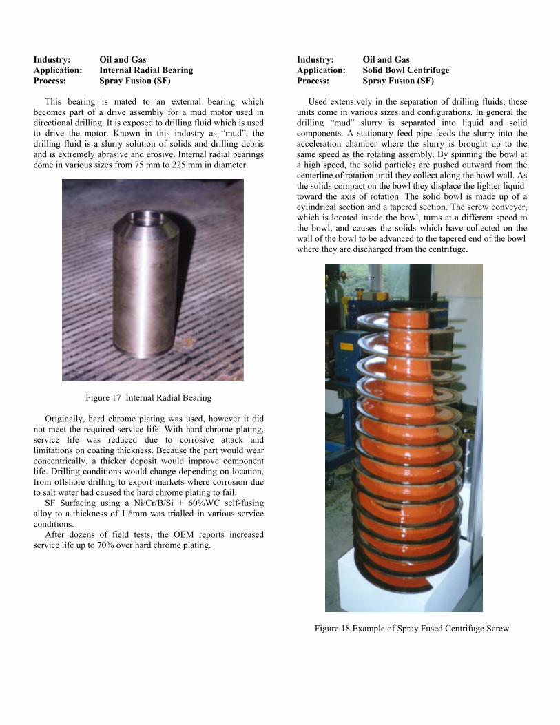
This bearing is mated to an external bearing which becomes part of a drive assembly for a mud motor used in directional drilling. It is exposed to drilling fluid which is used to drive the motor. Known in this industry as “mud”, the drilling fluid is a slurry solution of solids and drilling debris and is extremely abrasive and erosive. Internal radial bearings come in various sizes from 75 mm to 225 mm in diameter.
toward the axis of rotation. The solid bowl is made up of a cylindrical section and a tapered section. The screw conveyer, which is located inside the bowl, turns at a different speed to the bowl, and causes the solids which have collected on the wall of the bowl to be advanced to the tapered end of the bowl where they are discharged from the centrifuge.
Figure 17 Internal Radial Bearing
Originally, hard chrome plating was used, however it did not meet the required service life. With hard chrome plating, service life was reduced due to corrosive attack and limitations on coating thickness. Because the part would wear concentrically, a thicker deposit would improve component life. Drilling conditions would change depending on location, from offshore drilling to export markets where corrosion due to salt water had caused the hard chrome plating to fail. SF Surfacing using a Ni/Cr/B/Si + 60%WC self-fusing alloy to a thickness of 1.6mm was trialled in various service conditions. After dozens of field tests, the OEM reports increased service life up to 70% over hard chrome plating.
Figure 18 Example of Spray Fused Centrifuge Screw
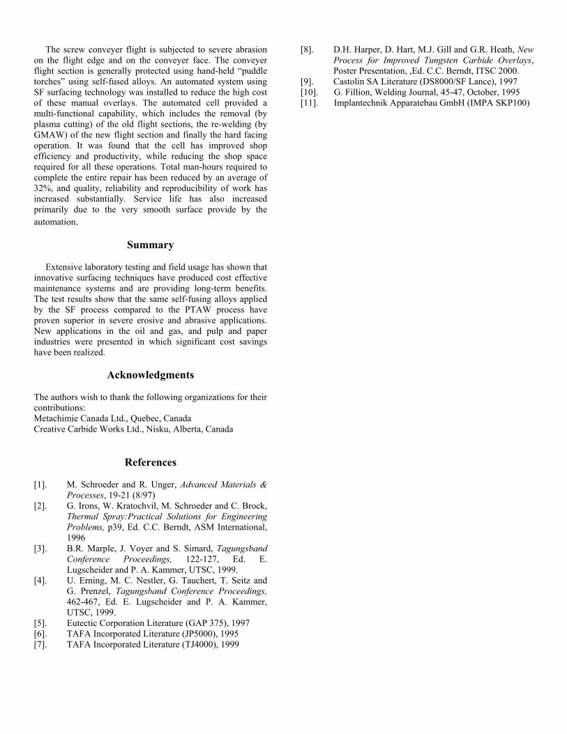
The screw conveyer flight is subjected to severe abrasion on the flight edge and on the conveyer face. The conveyer flight section is generally protected using hand-held “puddle torches” using self-fused alloys. An automated system using SF surfacing technology was installed to reduce the high cost of these manual overlays. The automated cell provided a multi-functional capability, which includes the removal (by plasma cutting) of the old flight sections, the re-welding (by GMAW) of the new flight section and finally the hard facing operation. It was found that the cell has improved shop efficiency and productivity, while reducing the shop space required for all these operations. Total man-hours required to complete the entire repair has been reduced by an average of 32%, and quality, reliability and reproducibility of work has increased substantially. Service life has also increased primarily due to the very smooth surface provide by the automation.
Summary Extensive laboratory testing and field usage has shown that innovative surfacing techniques have produced cost effective maintenance systems and are providing long-term benefits. The test results show that the same self-fusing alloys applied by the SF process compared to the PTAW process have proven superior in severe erosive and abrasive applications. New applications in the oil and gas, and pulp and paper industries were presented in which significant cost savings have been realized.
Acknowledgments The authors wish to thank the following organizations for their contributions: Metachimie Canada Ltd., Quebec, Canada Creative Carbide Works Ltd., Nisku, Alberta, Canada
References [1]. M. Schroeder and R. Unger, Advanced Materials &
Processes, 19-21 (8/97) [2]. G. Irons, W. Kratochvil, M. Schroeder and C. Brock,
Thermal Spray:Practical Solutions for Engineering Problems, p39, Ed. C.C. Berndt, ASM International, 1996
[3]. B.R. Marple, J. Voyer and S. Simard, Tagungsband Conference Proceedings, 122-127, Ed. E. Lugscheider and P. A. Kammer, UTSC, 1999.
[4]. U. Erning, M. C. Nestler, G. Tauchert, T. Seitz and G. Prenzel, Tagungsband Conference Proceedings, 462-467, Ed. E. Lugscheider and P. A. Kammer, UTSC, 1999.
[5]. Eutectic Corporation Literature (GAP 375), 1997 [6]. TAFA Incorporated Literature (JP5000), 1995 [7]. TAFA Incorporated Literature (TJ4000), 1999
[8]. D.H. Harper, D. Hart, M.J. Gill and G.R. Heath, New Process for Improved Tungsten Carbide Overlays, Poster Presentation, ,Ed. C.C. Berndt, ITSC 2000.
[9]. Castolin SA Literature (DS8000/SF Lance), 1997 [10]. G. Fillion, Welding Journal, 45-47, October, 1995 [11]. Implantechnik Apparatebau GmbH (IMPA SKP100)
Top Related