


Languages
Pages
Legal


DMT121 – ELECTRONIC DEVICES
CHAPTER 5FIELD-EFFECT TRANSISTOR (FET)
-MOSFET-

JFET vs BJT
JFET BJT
ID = IS IC ≈ IB
IG ≈ 0 A VBE ≈ 0.7 V
2
1
P
GSDSSD V
VII BC II

JFET vs BJT

MOSFET
MOSFET (Metal Oxide Semiconductor Field-Effect Transistor)
Different from JFET – no pn junction structure.
Gate of MOSFET is insulated from the channel by silicon dioxide (SiO2) layer.
2 types – enhancement and depletion.

DEPLETION-TYPE MOSFET
P-type material is formed from silicon substrate.
Source and Drain terminals are connected through metallic contacts to n-doped region linked by n-channel.
Gate connected to metal contact surface but insulated from n-channel by thin SiO2 layer – no direct connection gate and channel of MOSFET.
SiO2 is a dielectric which sets up opposing electric fields within the dielectric when exposed to externally applied field.
n-channel depletion-type MOSFET

BASIC OPERATION & CHARACTERISTICS @ VGS=0 V
Gate-to-Source voltage is set to 0 V.
A voltage VDS is applied across the Drain-to-Source terminals.
An attraction for positive potential at Drain by free electron of n-channel – produce current through channel.
At VGS = 0V, ID = IDSS

BASIC OPERATION & CHARACTERISTICS @ VGS<0 V
If VGS is set at a negative voltage:
Negative potential at Gate will pressure electron towards p-type substrate and attract holes from substrate.
Recombination between hole and electron will occur – reduce number of free electron in n-channel for conduction.
More negative the bias, recombination rate is higher.
ID is reduce with increasing negative bias of VGS.
At pinch-off voltage, VP, ID=0A

BASIC OPERATION & CHARACTERISTICS @ VGS>0 V
For positive value of VGS: Positive Gate will draw additional electron from p-
substrate due to reverse leakage current and established new carrier through the collisions between accelerating particles.
ID will increase at rapid rate – user must aware of ID maximum current rating.
Application of positive VGS has enhance the level of free carriers in the channel.
Region of positive gate voltage on drain or transfer curve is called enhancement region while region between saturation and cutoff is called depletion region.

BASIC OPERATION & CHARACTERISTICS

P-CHANNEL DEPLETION-TYPE MOSFET
Construction is reverse of n-channel. All voltage polarities and current direction are
reverse.

SYMBOL

ENHANCEMENT-TYPE MOSFET
Primary difference between depletion-type and enhancement-type is the absence of channel between Source and Drain terminals.
N-channel enhancement-type MOSFET
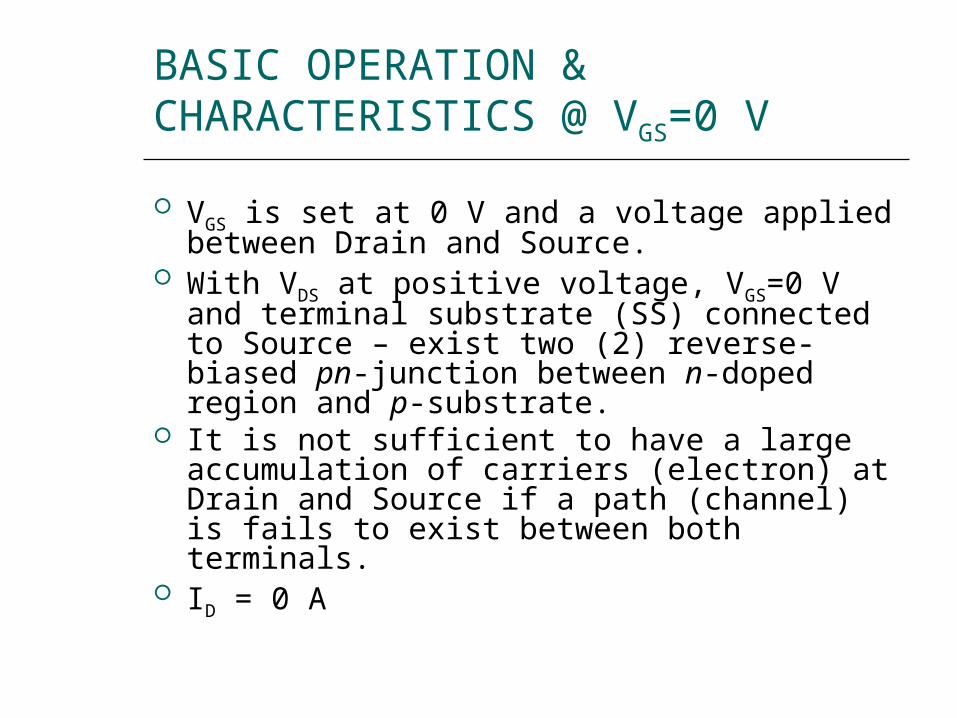
BASIC OPERATION & CHARACTERISTICS @ VGS=0 V
VGS is set at 0 V and a voltage applied between Drain and Source.
With VDS at positive voltage, VGS=0 V and terminal substrate (SS) connected to Source – exist two (2) reverse-biased pn-junction between n-doped region and p-substrate.
It is not sufficient to have a large accumulation of carriers (electron) at Drain and Source if a path (channel) is fails to exist between both terminals.
ID = 0 A

BASIC OPERATION & CHARACTERISTICS VGS>0 V
VDS and VGS>0 V: Positive potential at the Gate will
pressure the holes in p-sub along the edge of SiO2 to enter deeper p-sub.
Result in a depletion region near SiO2.
Electron in p-sub (minority carrier) attracted to positive Gate and accumulate in the region near the surface of SiO2 layer.
As VGS increase in magnitude, the concentration of electron increases until eventually induced n-type region to support current flow between Drain and Source.
The level of VGS that results in significant increase in ID is called threshold voltage, VT.

BASIC OPERATION & CHARACTERISTICS VGS>VT
VGS>VT: The density of free carriers in the
induced channel will increase - increased ID.
If increase VDS but VGS constant, ID will saturate.
VDG and Gate will become less and less positive with respect to Drain.
VDG=VDS-VGS
Reduction in Gate-to-Drain voltage will reduce the attractive forces for free carriers (electron) – reduction in channel width.
Channel will reduce to pinch-off and a saturation condition established.
Any further increase in VDS at fixed value of VGS will not affect the saturation level of ID until breakdown conditions are encountered.

BASIC OPERATION & CHARACTERISTICS
Saturation level for VDS is related to applied VGS by: VDsat = VGS – VT
VGS < VT, ID=0 A
VGS > VT, ID=k(VGS-VT)2

P-CHANNEL ENHANCEMENT-TYPE MOSFET
Construction is reverse of n-channel. All voltage polarities and current direction are
reverse.

SYMBOL

D-MOSFET BIASING
Similarities in appearance between transfer curve of JFET and D-MOSFET.
Primary difference: D-MOSFET permit operating points with positive value of VGS and level of ID that exceed IDSS.

D-MOSFET BIASINGSelf-Biased Configuration:

D-MOSFET BIASING
ID=IDSS(1-VGS/VP)2
Self-biased configuration results in VGS=-IDRS

D-MOSFET BIASING
Voltage-Divider Bias Configuration:

D-MOSFET BIASING
ID=IDSS(1-VGS/VP)2
Voltage-divider configuration results in:
VGS=VG-IDRS
Where VG=R2xVDD/(R1+R2)

E-MOSFET BIASING
Transfer curve for E-MOSFET is quite different from JFET and D-MOSFET.
ID=0 A if VGS<VT.
VGS>VT, ID=k(VGS-VT)2
2)(
)(
TonGS
onD
VV
Ik

E-MOSFET BIASINGVoltage-Divider Biasing

E-MOSFET BIASING
Voltage-divider configuration results in:
VGS=VG-IDRS
Where VG=R2xVDD/(R1+R2)
VDS=VDD-ID(RS+RD)
2)(
)(
TonGS
onD
VV
Ik

E-MOSFET BIASINGFeedback Biasing

E-MOSFET BIASING
IG=0 V VD=VG
VDS=VGS
VDS=VDD-IDRD
VGS=VDD-IDRD
When ID=0 A:
VGS=VDD
When VGS=0 V:
ID=VDD/RD

E-MOSFET BIASING
Top Related