


Languages
Pages
Legal


Directed cell growth and alignment on protein-patterned3D hydrogels with stereolithography
Vincent Chana,d$, Mitchell B. Collensa,d$, Jae Hyun Jeongb, Kidong Parkc,d,Hyunjoon Kongb and Rashid Bashira,c,d*
aDepartment of Bioengineering, University of Illinois at Urbana-Champaign, Urbana, Illinois, 61801, USAbDepartment of Chemical and Biomolecular Engineering, University of Illinois at Urbana-Champaign, Urbana,
Illinois, 61801, USAcDepartment of Electrical and Computer Engineering, University of Illinois at Urbana-Champaign, Urbana,
Illinois, 61801, USAdMicro and Nanotechnology Laboratory, University of Illinois at Urbana-Champaign, Urbana, Illinois, 61801, USA
(Received 2 July 2012; final version received 3 July 2012)
The stereolithography apparatus (SLA) is a computer-assisted, three-dimensional (3D)
printing system that is gaining attention in the medical field for the fabrication of patient-
specific prosthetics and implants. An attractive class of implantable biomaterials for the
SLA is photopolymerisable hydrogels because of their resemblance to soft tissues and
intrinsic support of living cells. However, most laser-based SLA machines lack the
minimum feature size required to imitate cell growth and alignment patterns in complex
tissue architecture. In this study, we demonstrate a simple method for aligning cells on 3D
hydrogels by combining the micro-contact printing (mCP) technique with the stereolitho-
graphic process. Fibronectin modified with acrylate groups was printed on glass coverslips
with unpatterned, 10, 50, and 100 mm wide line patterns, which were then transferred to
hydrogels through chemical linkages during photopolymerisation. Fibroblasts cultured on
protein-printed 3D hydrogels aligned in the direction of the patterns, as confirmed by fast
Fourier transform and cell morphometrics.
Keywords: stereolithography; micro-contact printing; hydrogels; cell alignment
1. Introduction
The stereolithography apparatus (SLA) is a computer-
assisted, three-dimensional (3D) printing system used for
creating complex structures from photopolymerisable resins
(Jacobs 1992). Traditionally, it is a manufacturing technique
intended to produce 3D models and prototypes, but practi-
tioners in the medical field have embraced it as a way to
develop custom end-use parts and preoperative surgical
plans (Barker et al. 1994, Winder and Bibb 2005). The SLA
and other 3D printing platforms have greatly improved the
performance and fit of prosthetics and implants in combina-
tion with computed tomography (CT) or magnetic reso-
nance imaging (MRI) technologies (Melchels et al. 2012).
Fabricated parts from the SLA have been implanted as
scaffolding for bone ingrowth (Cooke et al. 2003, Seitz et al.
2005), moulds for breast reconstruction (Melchels et al.
2011), replicas for aortic heart valves (Sodian et al. 2002),
and shells for ‘in-the-ear’ hearing aids.
In the past few years, photopolymerisable hydrogels have
been explored in the SLA as a potential class of implantable,
*Corresponding author. Email: [email protected]
$Both authors contributed equally for this study.
Virtual and Physical Prototyping
2012, 1�10, iFirst article
Virtual and Physical PrototypingISSN 1745-2759 print/ISSN 1745-2767 online # 2012 Taylor & Francis
http://www.tandfonline.comhttp://dx.doi.org/10.1080/17452759.2012.709423
soft materials (Melchels et al. 2010). Hydrogels, which
are networks of cross-linked polymers that imbibe large
amounts of water, can be used directly with living cells as a
synthetic extracellular matrix (ECM) analog for providing a
variety of physical, chemical, and biological cues (Nguyen
and West 2002, Ifkovits and Burdick 2007, Tibbitt and
Anseth 2009, Jabbari 2011). In contrast to stiff 2D substrates
made of polystyrene or glass, hydrogels possess 3D archi-
tecture and have tunable elasticity similar to tissues and
organs. Cell attachment (Nguyen and West 2002, Hadjipa-
nayi et al. 2009, Guillame-Gentil et al. 2010), spreading
(Wong et al. 2004, Discher et al. 2005, Bott et al. 2010),
communication (Reinhart-King et al. 2008, Geiger et al.
2009, Buxboim et al. 2010), and differentiation of stem cells
(Discher et al. 2005, Engler et al. 2006, Vogel and Sheetz
2006) are a few of the physical effects of matrix elasticity.
Poly(ethylene glycol) diacrylate (PEGDA) is the most
commonly used photopolymerisable hydrogel in the SLA.
Using the working curve equation (Jacobs 1992), PEGDA
with varying molecular weights was characterised for
building complex 3D structures (Arcaute et al. 2006). Living
cells encapsulated in PEGDA (]MW 1,000 g �mol�1)
survived the stereolithographic process and remained viable
within the hydrogel for up to two weeks (Chan et al. 2010).
Integrating living cells with PEGDA hydrogels patterned in
the SLA offers exciting new possibilities for tissue engineer-
ing and the development of cellular systems. For example,
the SLA was used to examine cell interactions of co-cultures,
such as neurons and muscle cells, encapsulated in discrete
spatial locales in the same 3D construct (Zorlutuna et al.
2011). In another example, geometric patterns of hydrogels
defined in the SLA were used to localise gradients of
angiogenic growth factors secreted by encapsulated fibro-
blasts. When implanted in vivo on a vascular membrane, new
blood vessels sprouted on the membrane in the same pattern
as the hydrogel (Jeong et al. 2012). Furthermore, the SLA
was modified for applications using multiple materials, such
as hydrogel cantilevers and actuators that mimic the
elasticity of the native myocardium for contractile muscle
cells (Chan et al. 2012).
Despite recent progress, the SLA is limited to minimum
feature sizes that are dependent on the diameter of the laser
beam. Commercial SLA systems utilise gas or solid-state
lasers that have a spot size between 75 and 250 mm. This
limits the ability of researchers interested in creating
patterns that control cell growth and alignment to imitate
the in vivo tissue architecture. Distinct patterns are seen
throughout the body, such as complex neural networks in
the brain and linear arrangement of muscle cells around the
myocardium (McDevitt et al. 2002). Protein immobilisation
for patterning has been shown on and in hydrogels (Khetan
and Burdick 2011) using thiol chemistry and two-photon
irradiation (Lee et al. 2008, West 2011), and photolitho-
graphy. Additionally, cell patterning has been shown
mechanically by creating grooves (Charest et al. 2006,
Park et al. 2006, Kim et al. 2007, Aubin et al. 2010),
microchannels (Sarig-Nadir et al. 2009), and geometric
restrictions (Parker et al. 2002, Aubin et al. 2010); however,
these methods can alter material properties and mechanics
which are important to maintain for specific applications.
In this current study, we exploited the cells’ dependence
on ECM molecules to control their growth, organisation,
and distribution. Specifically, we have developed a simple
method to align cells on structures fabricated using the SLA
by first stamping polydimethylsiloxane (PDMS) patterns of
acryl-fibronectin with micro-contact printing (mCP) and
transferring the patterns to hydrogels fabricated in the SLA.
This technique can then be used to align living cells on 3D
hydrogel geometries, including neurons, muscle cells, and
endothelial cells. From a biological perspective, the elastic
properties of hydrogels combined with the ability to align
cells allows for realistic in vitro models for understanding
the biology of cell development, organisation, and disease.
From an engineering perspective, using the SLA to create
geometrically-defined, biohybrid constructs generates ex-
emplary new applications in tissue engineering, regenerative
medicine, synthetic biology, and cellular machines.
2. Materials and methods
2.1 Preparation of PDMS stamp
Master moulds for the PDMS stamps were fabricated on a
silicon wafer with SU-8 negative photoresist following a
standard procedure (Chen et al. 1998, Kane et al. 1999). The
master moulds contained patterns of 10, 50, and 100 mm
wide lines with equal spacing. The height of each pattern was
5 mm. The patterned master moulds were silanised with
(tridecafluoro-1,1,2,2-tetrahydrooctyl)-1-trichlorosilane in
vacuum for 1 hour. PDMS (Dow Corning Sylgard 184
Silicone Elastomer Kit) was weighed out at a 10:1 ratio of
polymer-to-curing agent (heat activated). The materials were
thoroughly mixed for 3 minutes to ensure even distribution
of the curing agent and poured onto the patterned master
moulds. Samples were placed in a desiccator, pulled under
vacuum, and baked at 80 8C overnight.
2.2 Preparation of fibronectin and acryl-fibronectin ink
Fibronectin from bovine plasma solution (Sigma Aldrich,
St. Louis, MO, USA) was diluted in phosphate buffer
solution (PBS) to a concentration of 50 mg mL�1. For
acryl-fibronectin ink, monoacrylated poly(ethylene
glycol)-N-hydroxysuccinimide (acryl-PEG-NHS, MW 3500
g �mol�1, JenKem Technology, Allen, TX, USA) was
dissolved in PBS at a concentration of 30 mg mL�1. A
working solution of acryl-fibronectin ink was prepared by
mixing acryl-PEG-NHS with fibronectin at a 2:1 molar ratio
2 V. Chan et al.

of acrylate-to-lysine. Acryl-PEG-NHS reacts spontaneously
with primary amines on the fibronectin and releases N-
hydroxysuccinimide to form a covalent bond. The reaction
was allowed to proceed for 30 minutes at 4 8C.
2.3 Micro-contact printing ink on glass coverslips
Glass coverslips were patterned by mCP (Chen et al. 1998,
Kane et al. 1999) using clean PDMS stamps. Fibronectin
and acryl-fibronectin ink (50 mg mL�1) were coated onto
PDMS stamps for one hour at 37 8C. After incubation,
excess ink was aspirated and dried under a stream of N2.
Stamps were placed pattern-side down onto 18 mm2 glass
coverslips. Pressure was applied for 30 s to allow adsorption
of ink to the glass, and the coverslips were incubated for
45 minutes. Stamps were removed, and the coverslips were
used within one hour.
2.4 Preparation of hydrogel pre-polymer solution
Hydrogel pre-polymer solutions were prepared by dissol-
ving 20% poly(ethylene glycol) diacrylate (PEGDA, MW
3400 g �mol�1, Laysan Bio, Arab, AL USA) in PBS.
The photoinitiator, 1-[4-(2-hydroxyethoxy)-phenyl]-2-hy-
droxy-2-methyl-1-propane-1-one (Irgacure 2959, Ciba,
Basel, Switzerland), was diluted to a 50% (w/v) stock
solution in dimethyl sulfoxide (DMSO, Fisher Scientific).
A final concentration of 0.5% (w/v) was added to the pre-
polymer solution. All materials were prepared immediately
before photopolymerisation in the SLA.
2.5 Fabrication of photopolymerisable hydrogels
Hydrogel constructs were fabricated with a modified
stereolithography apparatus (SLA 250/50, 3D Systems,
Rock Hill, SC) (Chan et al. 2010). Cylindrical disks
(5 mm radius) were designed in AutoCAD 2012 (Autodesk,
San Rafael, CA USA) and prepared in 3D Lightyear v1.4
software (3D Systems, Rock Hill, SC) for cross-sectional
slicing into 2D layers. Parameters were specified based on
desired layer thickness. An 18 mm2 glass coverslip with
unpatterned and patterned lines of fibronectin or acryl-
fibronectin ink 10, 50, or 100 mm wide was fixed to a 35 mm
polystyrene dish with double-sided tape. Surfaces with no
patterns were always used as controls. The dish was coated
with hydrogel pre-polymer solution at a characterised
volume determined by desired layer thickness. It was
positioned at the centre of the SLA platform and photo-
polymerised with a characterised energy dose of 150 mJ
cm�2. After photopolymerisation, disks were rinsed in PBS
and allowed to swell overnight before cell seeding.
2.6 Cell culture
NIH/3T3 mouse embryonic fibroblasts (ATCC, Manassas,
VA USA) were cultured at 37 8C and 5% CO2 in Dulbecco’s
modified Eagle medium (DMEM, Cellgro, Manassas, VA
USA) supplemented with 10% foetal bovine serum (FBS,
Sigma-Aldrich, St. Louis, MO USA), 100 IU penicillin, and
100 mg ml�1 streptomycin (Gibco, Carlsbad, CA USA).
Cells were passaged no more than 10 times using 0.25%
trypsin and 0.04% ethylenediaminetetraacetic acid (EDTA)
in Hank’s balanced salt solution (HBSS) (Gibco, Carlsbad,
CA USA). Prior to cell seeding, hydrogel constructs were
positioned in 12-well plates with fibronectin and acryl-
fibronectin patterns facing up. Cells were then seeded at a
density of 90,000 cells cm�2 over the hydrogels.
2.7 Fluorescence immunostaining
To verify fibronectin transfer from patterned glass slides to
hydrogels, monoclonal anti-fibronectin produced in mouse
(Sigma-Aldrich, St. Louis, MO USA) was diluted at 1:300 in
PBS and added to the samples overnight at 4 8C. The
solution was then aspirated and rinsed three times with PBS.
Alexa Fluor 488 goat anti-mouse IgG (Life Technologies,
Grand Island, NY USA) was diluted at 1:1000 in PBS and
added for 2 hours at 37 8C. After rinsing three times with
PBS, the samples were imaged with an inverted fluorescence
microscope (IX81, Olympus, Center Valley, PA USA).
To visualise the morphology of fibroblasts on hydrogel
constructs, the cells were fixed and labelled at different time
points. For fixation, samples were rinsed with PBS and
incubated in 4% paraformaldehyde (PFA, Sigma-Aldrich,
St. Louis, MO USA) for 30 minutes. After rinsing three
times with PBS, a solution of 3,3?-dihexyloxacarbocyanine
iodide (DiOC6, Life Technologies) was added at 1:1000
dilution in PBS to stain for a cell’s endoplasmic reticulum,
vesicle membranes, and mitochondria. Samples were then
permeabilised with 0.1% Triton X-100 (Sigma Aldrich) for
10 minutes and blocked with 2.5% bovine serum albumin
(BSA) in PBS to prevent non-specific binding. Cell nuclei
were stained with a 1:1000 dilution of 2-(4-amidinophenyl)-
1H-indole-6-carboxamidine (DAPI, Life Technologies),
and actin was stained with a 1:1000 dilution of rhodamine
phalloidin (BD Biosciences). Fluorescent images were taken
with the inverted fluorescence microscope.
2.8 Fibronectin and acryl-fibronectin transfer to hydrogels
Image J software (Abramoff et al. 2004) was used for
analysis of fibronectin, acryl-fibronectin, and cell alignment
patterns. Transfer of fibronectin and acryl-fibronectin from
glass coverslips to hydrogels were confirmed quantitatively
by measuring the pixel intensity of fluorescent images.
To calculate pixel intensity values, a line profile was drawn
3Virtual and Physical Prototyping
across the image and grey values were extracted at each
point on the line. To determine the integrity and resolution
of patterns, line width measurements of mCP glass cover-
slips and patterned hydrogels were taken. The line profile
tool was used to draw horizontal lines perpendicular to
patterned lines on 40x images, and the measured line
widths were recorded.
2.9 Fast Fourier transform analysis
Fast Fourier transform (FFT) image processing analysis
was previously demonstrated for cell patterning on hydro-
gels (Millet et al. 2011). Briefly, Image J software was used
to enhance image contrast, subtract the background, and
filter noise from the image. Images were converted to the
frequency domain by FFT transformation and rotated 908to account for the inherent rotation that occurs during
transformation. A circle was drawn over the FFT image,
and the oval profile plugin was used to radially sum pixel
intensities around the circle. A power spectrum was
generated based on radially summated values, with
08 correlating to frequencies at 3 o’clock, 908 at 12 o’clock,
1808 at 9 o’clock, and 2708 at 6 o’clock.
2.10 Cell morphometrics analysis
The effect of patterning at the cellular level was analysed by
observing changes in cell shape, direction of cell elongation,
and orientation of nuclei. Post-image processing, a thresh-
old was applied to make a binary image and individual cells
were identified. Image J software object tools were used to
measure and compare the cell circularity and nuclear
orientation. Ten circularity bins of 0.1 intervals were set
up, and circularity values between 0 and 1 were placed in
each bin (0 being a line and 1 being a circle). Significance
was verified with a Student’s t-test statistical analysis.
Nuclear orientation was measured by using the ‘analyse
particles’ tool to fit an ellipse to threshold images of DAPI-
stained nuclei and measuring the angle of the ellipse.
Direction and length of cell elongation was determined by
measuring the angle and distance from the nucleus to the
furthest edge of the actin stained cell.
3. Results
3.1 Fibronectin transfer and pattern retention
To create patterns of proteins on 3D hydrogel constructs,
we modified fibronectin molecules with chemically linkable
acrylate groups for crosslinking to the backbone of
PEGDA hydrogels during photopolymerisation. This sim-
ple concept allowed us to utilise the mCP technique to
pattern acryl-fibronectin onto hydrogels prepared with the
SLA (Figure 1). We confirmed the transfer of acryl-
fibronectin from glass coverslips to hydrogels by quantita-
tive analysis of immunofluorescence imaging. Comparison
of hydrogels built on glass coverslips with fibronectin
(Figure 2A) and acryl-fibronectin (Figure 2B) showed that
acryl-fibronectin successfully transferred from the glass
coverslip to PEGDA (MW 3400 g �mol�1) hydrogels.
The average pixel intensity of acryl-fibronectin on hydrogels
was measured at 129910.9, while fibronectin on hydrogels
had an average pixel intensity of 2.690.5 (Figure 2C).
Patterned line widths of 10, 50, and 100 mm on glass
coverslips and hydrogels were measured to verify pattern
integrity after acryl-fibronectin transfer. Figure 3 shows
fluorescent images of patterned lines on glass coverslips and
hydrogels. The actual line widths were 11.590.4 mm,
49.191.8 mm, and 98.790.60 mm, respectively, after
PDMS stamping on glass coverslips (Figure 3A), and
13.490.5 mm, 57.390.6 mm, 110.595.8 mm, respectively,
after acryl-fibronectin transfer to the 3D hydrogel con-
structs (Figure 3B). Fibronectin transfer did not occur
without acrylate groups (Figure 3C). It is well-known that
PEGDA (MW 3400 g �mol�1) swells after photopolymerisa-
tion and subsequent washing in PBS. This phenomenon
caused the measured line widths on the hydrogels to be
greater than those on the glass coverslip (Figure 3D).
However, the average pixel intensity of fluorescently-
labelled acryl-fibronectin patterns on hydrogels did not
appear to decrease significantly to the extent that it would
affect cell alignment.
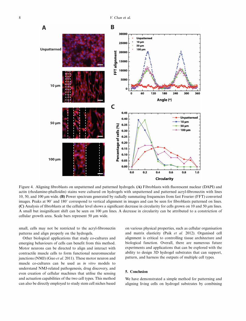
3.2 Cell growth and alignment on hydrogels
NIH/3T3 mouse embryonic fibroblasts were cultured on 3D
hydrogel constructs with acryl-fibronectin patterns of un-
patterned, 10, 50, and 100 mm wide lines to demonstrate
feasibility of cell alignment. The cells rapidly adhered to
and began to spread on the line patterns after one hour in
culture. Within 24 hours, the cells were activated to
proliferate along the line patterns. Figure 4A shows that
the cells recognised the acryl-fibronectin patterns and
aligned parallel to the lines. As the line spacing decrea-
sed from 100 to 10 mm, the number of cells that bridged
patterned lines increased. Regardless of cell bridging, the
cells continued to align parallel to the lines.
It was evident from the fluorescent images that as line
width patterns decreased, alignment of individual cells
increased. This was confirmed quantitatively with fast
Fourier transform analysis (Figure 4B). Conversion of
images to the frequency domain revealed directed fibroblast
growth and linear pattern formation. Distinct peaks were
seen in the power spectrum of fibroblasts grown on
patterned lines of all widths at 08 and 1808. Fibroblasts
grown on unpatterned hydrogels lacked these peaks and
had more uniformly-scattered spectrums. Furthermore, as
4 V. Chan et al.

the line widths increased, the peaks also decreased, and the
spectrums were more scattered.
Cell morphometrics were used to examine the individual
shape of cells on patterned and unpatterned 3D hydrogel
constructs. Growth of cells along the patterned lines altered
their shape, making them more linear. Figure 4C shows the
decreasing shift of cell circularity measurements between
patterned and unpatterned cells. Average circularity was
significantly different (Student’s t-test, P-values�1.97E-25
and 4.83E-25 for 10 and 50 mm lines, respectively) between
unpatterned fibroblasts (0.4190.22) and fibroblasts re-
stricted to growth on 10 mm (0.1590.10) and 50 mm
(0.1590.11) lines. Cell shape was altered on 100 mm lines
but was not statistically significant.
Figure 5 shows further analysis of the effect of acryl-
fibronectin patterns on cell shape and growth. Fibroblast
elongation, which was measured from the furthest edge of
stained actin on each side of the cell to the nucleus, was
parallel to line direction. Average angles were 90.98, 88.98,and 89.98 for 10, 50, and 100 mm lines, respectively.
Unpatterned fibroblasts had an average angle of 95.48which was significantly different than patterned fibroblasts
(Student’s t-test, P-values�4.6E-2, 4.9E-3, and 8.6E-4,
respectively). Standard deviations of the average angles
were 13.08, 27.38, and 48.08 for 10, 50, and 100 mm lines,
respectively. Length of elongation caused by patterning
showed a significantly greater difference. The average length
of extended actin in the cell was 44.33 mm for unpatterned
fibroblasts. Patterned cells had average lengths of 78.8, 54.9,
and 40.6 mm for 10, 50, and 100 mm lines, respec-
tively (Student’s t-test, P-values�9.16E-18, 6.78E-08, and
2.05E-4). The scatter plot in Figure 5A demonstrates
Figure 1. Patterning acryl-fibronectin hydrogels. (1) Silicon wafers were coated with 5 mm of SU-8 photoresist. (2) Line
patterns were formed after exposure of photoresist and silicon with UV light through a chrome mask. (3) PDMS was poured
over the silicon master and polymerised by baking. A negative of the pattern from the silicon master was imprinted on the
surface of the PDMS making a stamp. (4) An ink solution containing acryl-fibronectin was pipetted onto the PDMS stamp.
Acrylic fibronectin was made by mixing acryl-PEG-NHS and fibronectin in PBS and allowing the PEGDA cross-linker to
attach to free lysine groups in fibronectin. (5) After stamps were incubated with ink, line patterns were transferred to glass
slides by stamping. (6) Pre-polymer solution of PEGDA (MW 3400) and a photoactivator is poured into a dish over patterned
glass slides. (7) The dish containing pre-polymer and patterned glass is put into the stereolithography apparatus (SLA) and
polymerised to form a hydrogel. (8) 3D structures were built layer-by-layer adding additional pre-polymer before cross-
linking. (9) Hydrogels were inverted and seeded with cells. During building of the first layer, acryl-fibronectin was transferred
to the surface of the hydrogel allowing for cell attachment.
5Virtual and Physical Prototyping

clustering of the cell elongation around 908 for cells grown
on patterns, while the standard deviation plot in Figure 5B
shows that the spread of those angles is much smaller with
narrower line widths.
4. Discussion
Applications for the SLA and other 3D printing platforms
using living cells and cell-instructive 3D microenvironments
are expanding rapidly. However, none of these enabling
technologies are without their drawbacks, and continual
development is needed to accommodate the growing
number of applications. One of the current limitations of
commercial laser-based stereolithographic systems is the
minimum feature size required to imitate cell growth and
alignment patterns in complex tissue architecture. While
photopolymerisable hydrogels can be functionalised with
proteins and peptides to enhance cell attachment, it is
difficult to pattern them with the SLA at length scales
comparable to the cell size. Grooves, microchannels, and
other geometrically-restrictive techniques that affect the
topology of the hydrogels can alter mechanical properties,
which are important in many of these applications. There-
fore, micro-contact printing (mCP) offers the capability of
directing cell alignment on hydrogel structures without
compromising the benefit of creating complex 3D architec-
tures with the SLA. For example, 3D hydrogel cantilevers
Figure 2. Measuring the transfer of fibronectin and acryl-fibronectin on hydrogels. Hydrogels were fabricated on glass slides
with fluorescently-labelled fibronectin and acryl-fibronectin. (A) Fluorescent image of a hydrogel fabricated on a glass slide
with fibronectin. (B) Fluorescent image of a hydrogel built on a slide with acryl-fibronectin. (C) Using Image J software,
fluorescent intensity of fibronectin and acryl-fibronectin images were extracted and compared. Hydrogels with fibronectin had
an average intensity of 2.6, while those with acryl-fibronectin had an average intensity of 129.9. This confirmed that acryl-
fibronectin chemically cross-linked fibronectin to the hydrogels.
6 V. Chan et al.

fabricated with the SLA can be protein-patterned using our
mCP method to align cardiomyocytes for improved actua-
tion force (Chan et al. 2012).
Micro-contact printing (mCP) is a well-established tech-
nique that does not affect the mechanical properties of
hydrogels. It was chosen to pattern acryl-fibronectin in
combination with the SLA based on its ease of use,
compatible setup, and unrestricted variation in shapes and
sizes. Modification of fibronectin with acrylate groups
(acryl-fibronectin) was the key component to this method.
Without tethered ECM proteins or peptides, PEGDA
hydrogels are intrinsically resistant to protein adsorption
and cell adhesion. Based on low measured fluorescent
intensity, unmodified fibronectin did not transfer to the
PEGDA hydrogels (Figure 2A). In contrast, acryl-
fibronectin had uniform and high fluorescent intensity
throughout the surface of the hydrogels (Figure 2B). This
method is not restricted to fibronectin; other proteins or
peptides with free lysine (-NH3) groups, such as laminin,
collagen, and gelatin, can also be modified with acrylate
groups using the same method described.
PEGDA was chosen as the hydrogel material based on its
tunable swelling ratio, elastic modulus, and mesh size. It can
also be modified for cell-specific adhesion, enzyme-sensitive
or hydrolytic degradation, and growth factor-binding
signals (Zhu 2010). The swelling ratio and mesh size should
be large enough to allow for an adequate supply of oxygen
and nutrients, while the elastic modulus and patterning
resolution should be high enough for the specific applica-
tion. Figure 3, which compared the measured line widths on
glass coverslips and hydrogels, shows a decrease in the
patterning resolution on the PEGDA (MW 3400 g �mol�1)
hydrogels. By decreasing the MW of PEGDA, the patterning
resolution can be improved because of the reduced swelling,
but this can also affect the organisation and function of
cells on the hydrogels.
Although a variety of other configurations are possible,
we used line patterns to demonstrate directed cell growth
and alignment on the hydrogels. The widths of those line
patterns were varied to determine the length scale at which
cells would align on the hydrogels. If widths are too thin,
cell bodies may be larger than the lines, preventing
appropriate cell attachment; if widths are too wide, cells
may not recognise the patterns and align to them (Dike
et al. 1999). Previous findings show that individual cells
can recognise lines measuring 5�100 mm wide (Kaji et al.
2003). Trends in our data support these findings, with
single cells patterning to 10�50 mm wide lines and multiple
cells patterning to 100 mm wide lines. In addition, a
reduction in circularity can be seen, length of cell
elongation, and angle of cell elongation differs between
cells grown on patterned lines opposed to unpatterned
cells.
Line spacing was also varied to determine length scales at
which ‘bridging’ of cells between patterns occurred. This
could prove useful for applications that require cell-cell
connections between patterns or formation of cell sheets,
without disturbing their alignment. For example, it is
known that the complex organisation of cardiac muscle
cells and fibroblasts is critical to electrical and mechanical
properties in the heart. Because of this, biological canti-
levers and actuators cultured with aligned sheets of
contractile muscle cells could generate more force than
unaligned sheets. Cell bridging would synchronise contrac-
tion of the aligned muscle cells and increase density of cells
on the devices. However, an optimum line width and
spacing would need to be characterised to maximise the
performance of the muscle cell sheet. If line spacing was too
Figure 3. Transferring fibronectin patterns from glass coverslips to hydrogels. (A) Glass coverslips with fluorescently-labelled
acryl-fibronectin lines 10, 50, and 100 mm wide. (B) Hydrogels with fluorescently-labelled acryl-fibronectin lines 10, 50, and
100 mm wide transferred from glass coverslips. (C) Hydrogels with fluorescently-labelled fibronectin lines 10, 50, and 100 mm
wide (control). (D) Comparison of measured line widths on glass coverslips and hydrogels. Scale bars represent 50 mm wide.
7Virtual and Physical Prototyping
small, cells may not be restricted to the acryl-fibronectin
patterns and align properly on the hydrogels.
Other biological applications that study co-cultures and
emerging behaviours of cells can benefit from this method.
Motor neurons can be directed to align and interact with
contractile muscle cells to form functional neuromuscular
junctions (NMJ) (Guo et al. 2011). These motor neuron and
muscle co-cultures can be used as in vitro models to
understand NMJ-related pathogenesis, drug discovery, and
even creation of cellular machines that utilise the sensing
and actuation capabilities of the two cell types. This method
can also be directly employed to study stem cell niches based
on various physical properties, such as cellular organisation
and matrix elasticity (Paik et al. 2012). Organised cell
alignment is critical to controlling tissue architecture and
biological function. Overall, there are numerous future
experiments and applications that can be explored with the
ability to design 3D hydrogel substrates that can support,
pattern, and harness the outputs of multiple cell types.
5. Conclusion
We have demonstrated a simple method for patterning and
aligning living cells on hydrogel substrates by combining
Figure 4. Aligning fibroblasts on unpatterned and patterned hydrogels. (A) Fibroblasts with fluorescent nuclear (DAPI) and
actin (rhodamine-phalloidin) stains were cultured on hydrogels with unpatterned and patterned acryl-fibronectin with lines
10, 50, and 100 mm wide. (B) Power spectrum generated by radially summating frequencies from fast Fourier (FFT) converted
images. Peaks at 908 and 1808 correspond to vertical alignment in images and can be seen for fibroblasts patterned on lines.
(C) Analysis of fibroblasts at the cellular level shows a significant decrease in circularity for cells grown on 10 and 50 mm lines.
A small but insignificant shift can be seen on 100 mm lines. A decrease in circularity can be attributed to a constriction of
cellular growth area. Scale bars represent 50 mm wide.
8 V. Chan et al.

the micro-contact printing (mCP) technique with the
stereolithographic process. The key component of this
method was acryl-fibronectin, which could be patterned
onto glass surfaces and transferred to photopolymerisable
PEGDA hydrogels. NIH/3T3 mouse embryonic fibroblasts
were cultured on hydrogels patterned with acryl-fibronectin
of various line widths. While resolution of the line widths
depended on swelling ratios of the hydrogels, it did not
visibly affect cell attachment or alignment on the patterns.
Analysis of cells cultured on the hydrogels showed cells
spreading and growing parallel to the direction of the lines.
Cell ‘bridging’ occurred between patterns and increased as
line spacing decreased. Overall, mCP can be used to enhance
cell-based applications with the SLA by patterning proteins
of various shapes and size on photopolymerisable hydrogels
for directed cell growth and alignment. It can be used to
increase hierarchical organisation of cells in engineered
biohybrid systems, or to expand our understanding of
developmental biology and the mechanism of diseases.
Acknowledgements
We thank Elise Corbin for her help with figures. This
project was funded by the National Science Foundation
(NSF), Science and Technology Center (STC) and Emer-
ging Behaviors in Integrated Cellular Systems (EBICS)
Grant CBET-0939511 (R.B. and H.K.) and by a coopera-
tive agreement that was awarded to University of Illinois at
Urbana-Champaign (UIUC) and administered by the U.S.
Army Medical Research & Materiel Command
(USAMRMC) and the Telemedicine & Advanced Technol-
ogy Research Center (TATRC), under Contract #:
W81XWH0810701.
References
Abramoff, M.D., Magalhaes, P.J. and Ram, S.J., 2004. Image processing
with ImageJ. Biophotonics International, 11 (7), 36�42.
Arcaute, K., Mann, B.K. and Wicker, R.B., 2006. Stereolithography of
three-dimensional bioactive poly(ethylene glycol) constructs with encap-
sulated cells. Annals of Biomedical Engineering, 34 (9), 1429�1441.
Aubin, H., et al., 2010. Directed 3D cell alignment and elongation in
microengineered hydrogels. Biomaterials, 31 (27), 6941�6951.
Barker, T.M., Earwaker, W.J. and Lisle, D.A., 1994. Accuracy of stereo-
lithographic models of human anatomy. Australasian Radiology, 38 (2),
106�111.
Bott, K., et al., 2010. The effect of matrix characteristics on fibroblast
proliferation in 3D gels. Biomaterials, 31 (32), 8454�8464.
Buxboim, A., Ivanovska, I.L. and Discher, D.E., 2010. Matrix elasticity,
cytoskeletal forces and physics of the nucleus: How deeply do cells ‘‘feel’’
outside and in? Journal of Cell Science, 123 (Pt 3), 297�308.
Chan, V., et al., 2010. Three-dimensional photopatterning of hydrogels
using stereolithography for long-term cell encapsulation. Lab on a Chip,
10 (16), 2062�2070.
Chan, V., et al., 2012. Multi-material bio-fabrication of hydrogel cantilevers
and actuators with stereolithography. Lab on a Chip, 12 (1), 88�98.
Charest, J.L., et al., 2006. Combined microscale mechanical topography
and chemical patterns on polymer cell culture substrates. Biomaterials,
27 (11), 2487�2494.
Chen, C.S., et al., 1998. Micropatterned surfaces for control of cell shape,
position, and function. Biotechnology Progress, 14 (3), 356�363.
Cooke, M.N., et al., 2003. Use of stereolithography to manufacture critical-
sized 3D biodegradable scaffolds for bone ingrowth. Journal of Biome-
dical Materials Research. Part B, Applied Biomaterials, 64 (2), 65�69.
Dike, L.E., et al., 1999. Geometric control of switching between growth,
apoptosis, and differentiation during angiogenesis using micropatterned
substrates. In Vitro Cellular and Developmental Biology - Animal, 35 (8),
441�448.
Discher, D.E., Janmey, P. and Wang, Y.L., 2005. Tissue cells feel and
respond to the stiffness of their substrate. Science, 310 (5751), 1139�1143.
Engler, A.J., et al., 2006. Matrix elasticity directs stem cell lineage
specification. Cell, 126 (4), 677�689.
Geiger, B., Spatz, J.P. and Bershadsky, A.D., 2009. Environmental sensing
through focal adhesions. Nature Reviews Molecular Cell Biology, 10 (1),
21�33.
Figure 5. Measuring direction of cell elongation of fibroblasts. (A) Cell elongation and direction were measured by drawing a
line from the nucleus to the furthest extended edge of the cell. Scatter distribution shows clustering of cell elongation near 908for fibroblasts grown on 10 and 50 mm lines. Unpatterned cells were significantly different in both elongation and uniform
distribution of edge direction. (B) Standard deviation of angle values for cell process alignment shows smaller spread values
for narrower line widths, which demonstrates higher alignment of cells.
9Virtual and Physical Prototyping

Guillame-Gentil, O., et al., 2010. Engineering the extracellular environ-
ment: Strategies for building 2D and 3D cellular structures. Advanced
Materials, 22 (48), 5443�5462.
Guo, X., et al., 2011. Neuromuscular junction formation between human
stem cell-derived motoneurons and human skeletal muscle in a defined
system. Biomaterials, 32 (36), 9602�9611.
Hadjipanayi, E., Mudera, V. and Brown, R.A., 2009. Guiding cell
migration in 3D: A collagen matrix with graded directional stiffness.
Cell Motility and the Cytoskeleton, 66 (3), 121�128.
Ifkovits, J.L. and Burdick, J.A., 2007. Review: Photopolymerizable and
degradable biomaterials for tissue engineering applications. Tissue
Engineering, 13 (10), 2369�2385.
Jabbari, E., 2011. Bioconjugation of hydrogels for tissue engineering.
Current Opinion in Biotechnology, 22 (5), 655�660.
Jacobs, P.F., 1992. Rapid prototyping and manufacturing: Fundamentals of
stereolithography. Dearborn, MI: Society of Manufacturing Engineers.
Jeong, J.H., et al., 2012. ‘‘Living’’ microvascular stamp for patterning of
functional neovessels; orchestrated control of matrix property and
geometry. Advanced Materials, 24 (1), 58�63.
Kaji, H., et al., 2003. Intracellular Ca2� imaging for micropatterned
cardiac myocytes. Biotechnology and Bioengineering, 81 (6), 748�751.
Kane, R.S., et al., 1999. Patterning proteins and cells using soft lithography.
Biomaterials, 20 (23�24), 2363�2376.
Khetan, S. and Burdick, J.A., 2011. Patterning hydrogels in three dimensions
towards controlling cellular interactions. Soft Matter, 7 (3), 830�838.
Kim, J., et al., 2007. Establishment of a fabrication method for a long-term
actuated hybrid cell robot. Lab on a Chip, 7 (11), 1504�1508.
Lee, S.-H., Moon, J.J. and West, J.L., 2008. Three-dimensional micropattern-
ing of bioactive hydrogels via two-photon laser scanning photolithography
for guided 3D cell migration. Biomaterials, 29 (20), 2962�2968.
McDevitt, T., Angello, J. and Whitney, M., 2002. In vitro generation of
differentiated cardiac myofibers on micropatterned laminin surfaces.
Journal of Biomedical Materials Research, 60 (3), 472�479.
Melchels, F., Feijen, J. and Grijpma, D.W., 2010. A review on stereolitho-
graphy and its applications in biomedical engineering. Biomaterials, 31
(24), 6121�6130.
Melchels, F., et al., 2011. CAD/CAM-assisted breast reconstruction.
Biofabrication, 3 (3), 034114.
Melchels, F. et al., 2012. Additive manufacturing of tissues and organs.
Progress in Polymer Science, 37 (8), 1079�1104
Millet, L.J., et al., 2011. Pattern analysis and spatial distribution of neurons
in culture. Integrative Biology, 3 (12), 1167�1178.
Nguyen, K.T. and West, J.L., 2002. Photopolymerizable hydrogels for tissue
engineering applications. Biomaterials, 23 (22), 4307�4314.
Paik, I. et al., 2012. Rapid micropatterning of cell lines and human
pluripotent stem cells on elastomeric membranes. Biotechnology and
Bioengineering, April 17. http://onlinelibrary.wiley.com/doi/10.1002/bit.
24529/abstract [Epub ahead of print]
Park, J., et al., 2006. Fabrication of complex 3D polymer structures for cell�polymer hybrid systems. Journal of Micromechanics and Microengineering,
16 (8), 1614�1619.
Parker, K.K., et al., 2002. Directional control of lamellipodia extension by
constraining cell shape and orienting cell tractional forces. FASEB
Journal, 16 (10), 1195�1204.
Reinhart-King, C.A, Dembo, M. and Hammer, D.A., 2008. Cell-cell
mechanical communication through compliant substrates. Biophysical
Journal, 95 (12), 6044�6051.
Sarig-Nadir, O., et al., 2009. Laser photoablation of guidance microchan-
nels into hydrogels directs cell growth in three dimensions. Biophysical
Journal, 96 (11), 4743�4752.
Seitz, H., et al., 2005. Three-dimensional printing of porous ceramic
scaffolds for bone tissue engineering. Journal of Biomedical Materials
Research. Part B, Applied Biomaterials, 74 (2), 782�788.
Sodian, R., et al., 2002. Application of stereolithography for scaffold
fabrication for tissue engineered heart valves. ASAIO Journal, 48 (1),
12�16.
Tibbitt, M.W. and Anseth, K.S., 2009. Hydrogels as extracellular matrix
mimics for 3D cell culture. Biotechnology and Bioengineering, 103 (4),
655�663.
Vogel, V. and Sheetz, M., 2006. Local force and geometry sensing regulate
cell functions. Nature Reviews Molecular Cell Biology, 7 (4), 265�275.
West, J.L., 2011. Protein-patterned hydrogels: Customized cell microenvir-
onments. Nature Materials, 10 (10), 727�729.
Winder, J. and Bibb, R., 2005. Medical rapid prototyping technologies:
State of the art and current limitations for application in oral and
maxillofacial surgery. Journal of Oral and Maxillofacial Surgery, 63 (7),
1006�1015.
Wong, J.Y., Leach, J.B. and Brown, X.Q., 2004. Balance of chemistry,
topography, and mechanics at the cell�biomaterial interface: Issues and
challenges for assessing the role of substrate mechanics on cell response.
Surface Science, 570 (1�2), 119�133.
Zhu, J., 2010. Bioactive modification of poly (ethylene glycol) hydrogels for
tissue engineering. Biomaterials, 31 (17), 4639�4656.
Zorlutuna, P., et al., 2011. Stereolithography-based hydrogel microenviron-
ments to examine cellular interactions. Advanced Functional Materials,
21 (19), 3642�3651.
10 V. Chan et al.
Top Related