


Languages
Pages
Legal


Design considerations for carbon steel pipes materials’ selection
applied in fossil powered plants subjected to wet-steam flow-
accelerated-corrosion
Peter Dobson a*
, Zulfiquar Ahmad Khan a
a School of Design, Engineering and Computing, Bournemouth University,
Talbot Campus, Fern Barrow, Dorset, BH12 5BB, UK
*Corresponding author. Tel.: (+44)07972 660019
E-mail addresses: [email protected] (P. Dobson), [email protected] (Z.A. Khan)
Abstract - FAC has only been recognized in the past three to four decades as a corrosion mechanism and has not been
greatly understood until recently. There are a wide range of factors that affect the rate of FAC including chemistry,
geometry and physical conditions inside the pipe. It is interesting to comprehend all of the factors of FAC within a steam
pipe with two-phase flow to see how the temperature makes a difference to the corrosion rates. There are certain unique
aspects of steam piping for fossil plants due to its fluid dynamics and control. The analysis of FAC will bring together
different aspects using calculated examples and describe how they occur in detail, it gives awareness of the factors and
how to calculate their effects. Safety and the integrity of the pipe have been carefully considered and methodologies of
reducing FAC have been defined.
Keywords: two-phase steam, magnetite, corrosion allowance, wall thinning, Reynolds number
1.0 Introduction
1.1 The problem
Carbon steel pipes are often used for the transportation of steam in power generation plants. The fossil fuel is
burnt in the boiler furnace and the energy released is used heat water, in pipes inside the boiler, and turn it into
steam. Steam has been widely used as a means of transporting energy and was especially prevalent in the
Victorian era. In power generation this steam is used to rotate a turbine which then turns a magnet inside a coil
or vice versa to generate electricity.
Today power plants alter the amount of electricity they produce by predicting the demand. Meaning that not all
power plants generators will be working at 100% all of the time. Usually power stations use dry superheated
steam as it is much more energy efficient, but due to changes in demand the temperature of the steam can drop
into the wet-steam region, wet steam is also known as two-phase steam or flow, additionally a liquid is known
as single-phase (flow). Superheated steam does not cause corrosion as it has no water as the water in
superheated steam has been further heated above the evaporating temperature where water cannot exist [17].
The main advantage of this is that this steam can contain more energy. Wet-steam causes a much greater rate of
corrosion in the pipe than superheated steam. The corroded material gets carried away in the flow of steam
causing an uneven surface of the inside wall and the material entrained in the flow can damage the turbines.
The uneven surface of the pipe wall causes turbulence and eddies in the flow and this accelerates the rate of
corrosion in the pipe, this is process is described as flow-accelerated-corrosion (FAC). The issue with FAC is

2
that it causes the walls of the pipe to thin at an increasing rate. Eventually the walls of the pipe get so thin that
the pressure of the steam causes the pipe to fail by cracking, even small cracks and low levels of corrosion can
affect the efficiency of the pipeline. The spontaneous failure can lead to down time for repairs of the pipe and
potentially damages surrounding assets and the repairs and down time cost money.
There are several case studies of steam a pipe rupturing due to FAC and below is a table of a selection of those
cases;
1.2 Contributions to knowledge
There are many different factors that affect the carbon steel pipes as well as the corrosion issue, such as the
pressure of the steam and effects of stress and strain. In this paper we describe the correct design methodologies
for steam pipes in fossil power plants so that the steam pipes have the desired design life and do not fail
prematurely, causing down time and potential damage to other plant assets.
We will explain clearly what FAC is and how it can occur. We will also outline the various forms of corrosion
that can occur internally on the steam pipeline.
We will describe in detail the effects of FAC and relate them to the steam temperature and the time the pipe is
subjected to that temperature.
Material choices for the pipes will be outlined such as different alloys and the corrosion allowances that need to
be calculated for certain features and situations.
Stress and strain calculations are key to ensure the structural rigidity and safety of the pipeline system, so not
only will the pipeline be considered, suggestions to the positioning of other features such as pipeline supports
will be included in the report.
Table 1 – FAC cases, [3]

3
2.0 Corrosion Deposit Removal Issues
2.1 FAC and EC
The issue is when water is present in the pipes, various forms of corrosion or erosion can take place on the
carbon steel. Erosion-corrosion (EC) is very similar to FAC, however FAC is the correlation between
increasing flow and increasing corrosion, also the oxide layer is dissolved or prevented from forming and EC is
the mechanical removal of corrosion deposits or oxide layer by shear stress from the flow of the fluid, EC is
also has impingement and turbulence corrosion under its definition and leaves grooves and pits in which the
local flow conditions can be seen. The two are very closely interlinked and are dependent on each other and
they have very similar variables between them. These variables include: the temperature of the fluid, fluid’s
velocity, pipe’s geometry, steel alloying elements, fluid’s pH. We will be referring to FAC however it may
technically be EC since they have such similar factors that affect them.
As a general rule the corrosion rate increases as the velocity increases and the type of corrosion changes from
general or uniform corrosion to EC and finally cavitation [24]. Increasing temperature causes an increase in
corrosion rates as corrosion is an electrochemical process and increasing temperature gives more energy into
the process allowing molecules to move with greater momentum.
2.1 Electrochemistry of FAC
When water droplets sit on the steels surface the metal has a tendency to release metal ions into the water until
there is equilibrium of ion concentration. The release of metal ions causes loss of material (dissolution) of the
metal. Eventually there is a build-up of electrons in the metal and positive ions in the electrolyte at this stage
the potential difference between the metal and the liquid is equal to the equilibrium potential (just enough
voltage to allow same rate of transfer both ways of ions) rate at the ion concentration obtained in the liquid.
[24]
The reaction rate in each direction can be expressed by the rate of electric charges, i.e. by current or current
density called the exchange current (density). In equilibrium where there is no net transfer of ions, the exchange
current is zero. The exchange current depends on electrode reaction, electrode material and electrolyte.
Temperature and concentrations also affect the exchange current significantly. Increasing temperature,
conditions steam pipes are subjected to, relates to an increasing current this is because the viscosity of the
liquid reduces so the boundary layer is thinner and this leads to increased diffusion [13].
Iron in steel gives up its ions to the solution as iron has good ability to dissolve as it is quite active / not noble.
To balance this loss of ions the metal has to be charged relatively negative this means steel has a negative
equilibrium potential. The larger the activity of ions in the solution the more ions are released into the solution
to balance this higher rate of ion release a positive pressure is needed in the steel, thus with increasing ion
release activity the equilibrium potential increases. [2]
When the potential is moved away from the equilibrium potential it is said that the electrode is polarized, the
measure of the polarization is the overvoltage or over- potential (i.e. a net current in one direction) . There are
two ways that polarization can occur activation polarization where there is a resistance at the electrode interface
that acts against the current (overvoltage is needed to cope with this resistance) and is caused by the resistance

4
against the reaction. Concentration polarization is where there is either a shortage of reactants or an
accumulation of reaction products. [24]
If a metal is in equilibrium with its ions in the solution and then made more positive by external measures or by
polarization (potential is more +ve than the equilibrium potential) an oxidisation reaction (dissolution) of the
metal occurs as it tries to balance with the solution again. Resulting in greater metal losses. [11]
Destruction of the passive films in EC occurs mainly due to mechanical breakdown whereas in FAC the
breakdown is either due to chemical or electrochemical destruction. In chemical destruction the film is
dissolved as even the oxide layer has a degree of solubility. By changing the pH, temperature or concentration
of aggressive species (destructive species e.g. acids) the solubility is so high that even the passive films can
disappear. Electrochemical destruction occurs because by potential changes. Lowering the potential from the
passive region to the active region (this is illustrated in Pourbaix diagrams) or increasing it into the transpassive
region, in these regions the exchange current is increasing positively greater than the equilibrium potential
leading to activation. (E.g. for Fe in moderately alkaline environment a passive oxide can be reduced to other
oxides or to the metallic state). If there is an opening in the film under these conditions the substrate metal
corrodes rapidly and the film may be undercut with newer corrosion products. [2]
This is a case study of research done by General Electric into one failure they encountered from FAC corrosion
deposits this illustrates the issues that can occur due to the process described. “Superheated steam turbines are
particularly prone to damage by carryover. Sticking of governor and stop valves due to corrosion deposits can
cause turbine over-speed and catastrophic damage. Solid particles in steam can erode turbine parts, while
deposition on turbine blades can reduce efficiency and capacity. Losses of 5% in turbine efficiency and 20% in
turbine capacity have occurred due to deposition. When large slugs of boiler water carry over with steam, the
resulting thermal and mechanical shock can cause severe damage.” [7]
3.0 Influences to FAC
3.1 Corrosion Deposits
Knowing the process of corrosion and why it happens allows for the detailed explanation of FAC corrosion
process. Water droplets can form in the superheated steam when the pressure or temperature drops, it is
calculated so that this doesn’t happen on the way to the turbine as the droplets can damage the blades and off
balance the turbine causing damage to the whole turbine and rotor. This temperature drop can be caused by
various reasons and the conditions can be calculated from the ideal gas equation;
Superheated steam has very little or no oxygen in it due to the control of dissolved oxygen in the water [14]. So
when steel is exposed to the oxygen-free water the following reaction occurs;
Fe + 2H2O Fe2+
+ 2OHˉ +H2 Fe(OH)2 + H2
Due to the anaerobic conditions there is no oxygen that normally causes Fe(OH)2 or Fe(III) to form the oxide
layer. Instead magnetite (Fe3O4 or Fe(II,III)) forms the protective layer. This is shown in the ‘Schikorr’
reaction;

5
3Fe(OH)2 ⇒ Fe3O4 + 2H2O + H2
The magnetite inhibits further oxidisation of the steel however magnetite is soluble in demineralized neutral
water or slightly alkaline (pH range of 7 – 9.2) and low dissolved oxygen water. In these conditions a protective
layer of magnetite may not form[16]. Ammonia (pH=11) is sometimes added to the water to increase the pH
above the region where magnetite is soluble. [9,14]
If the flow velocity is high enough the Fe2+
ions generated get carried away from the steel surface before they
can create a magnetite layer. Turbulence in the flow from changes in path geometry increase the likelihood of
FAC and the entrainment of Fe2+
is greatly enhanced and or the dissolution of the magnetite oxide film occurs
more rapidly [9].
In two-phase flow the maximum rate of FAC at the temperature range of 150˚C which is around 2000
μg/cm2 hr this can be seen in Figure 1. This is due to the magnetite layer being porous and irregular [13].
Even in normal or maximum operating conditions water can still exist in the pipes due to carryover where water
(and other solids and vapour contaminates) get entrained into the flow of the steam from the boiler. This can
cause both FAC and EC [8].
3.2 Pipe Lifetime
The pipe thickness is calculated using;
Figure 1- Wear rates and temperature, [3]

6
Where: P is the max. internal service pressure, D’ is the outer diameter of the pipe, SE is the max. allowable
stress in material caused by internal pressure at the design temperature, y is a coefficient (0.4 below 428ºC) and
A is an allowance for corrosion and mechanical strength [19].
Calculating the estimated life of a pipe 10mm thickness at the maximum corrosion rate temperature to estimate
the time before the pipe is deemed unacceptable. Given the corrosion allowance is 0.165mm for pipes of
3.2mm or greater thickness [19] so this allowance is added to the 10mm thickness and the pipe is manufactured
to 10.165mm thickness. EU regulations dictate that if the thickness of the pipeline falls below 85% [11] of its
original thickness then it is unsafe and needs replacing. Which in this example would be a thickness of 8.64mm
a change of 1.525mm material loss in a 1cm2 element. This would be a mass loss of 1.188x10
-3kg and this
would take 595 hours of service. This seems very rapid however the pipes don’t always operate at these
conditions. They operate at higher temperatures where corrosion rate is lower. It is also not surprising as wall
thinning rates of over 3mm per year have been observed [5].
3.2 Stress Calculations
Knowing the elastic limit of low carbon steel is around 300MPa [18] and an internal diameter of 1m and the
optimum radial pressure of steam pipes is around 30 bar or 3MPa [15]. The minimum thickness of the pipe
needs to be found:
Figure 2- Stress and strain pipes, [25]
7
This has not taken into account any allowances for corrosion, joints or allowable stresses. Using pressure rating
tables and finding the closest values the maximum allowable stress is 13.2MPa [12]. Using this stress in
equation 3 gives a thickness of 11.4 mm. If we use equation 2 to find the thickness and ignore the sources
recommended corrosion and mechanical allowance and compare it later.
If we add their recommended 0.165mm we get 11.035 mm. This is only 3.3% difference to the thickness we
calculated using equation 3. It is also lower than the 11.4mm calculated before showing that their recommended
allowance is too small.
Knowing that the maximum FAC corrosion rate is 2000 μg/cm2 hr, and the method outlined before where we
used this to calculate the estimated lifetime for a pipe of 10mm thickness, combining this with equation 4 we
can accurately calculate a thickness for the pipeline for the desired number of service years using the following
derived equation:
σ2 has changed to σA as the maximum allowable stress found from pressure rating tables. Yrs is the number of
years of service and t is measured in meters. It is worth noting that this formula is only for FAC in pipes and
that it is only an estimation as other factors and types of corrosion discussed before can affect the rates.
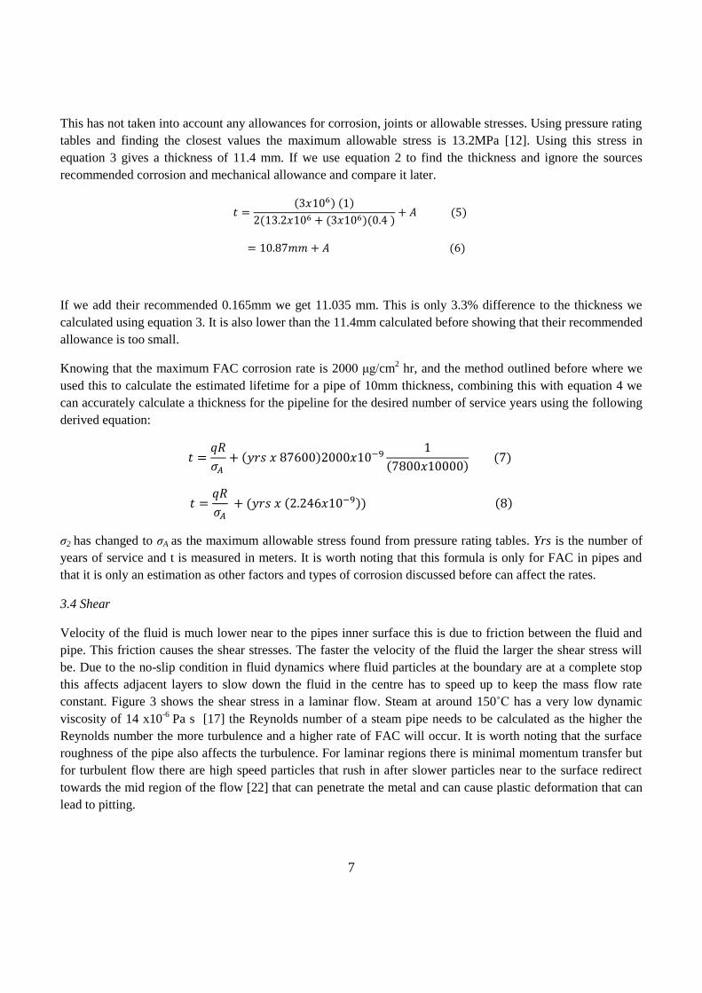
3.4 Shear
Velocity of the fluid is much lower near to the pipes inner surface this is due to friction between the fluid and
pipe. This friction causes the shear stresses. The faster the velocity of the fluid the larger the shear stress will
be. Due to the no-slip condition in fluid dynamics where fluid particles at the boundary are at a complete stop
this affects adjacent layers to slow down the fluid in the centre has to speed up to keep the mass flow rate
constant. Figure 3 shows the shear stress in a laminar flow. Steam at around 150˚C has a very low dynamic
viscosity of 14 x10-6
Pa s [17] the Reynolds number of a steam pipe needs to be calculated as the higher the
Reynolds number the more turbulence and a higher rate of FAC will occur. It is worth noting that the surface
roughness of the pipe also affects the turbulence. For laminar regions there is minimal momentum transfer but
for turbulent flow there are high speed particles that rush in after slower particles near to the surface redirect
towards the mid region of the flow [22] that can penetrate the metal and can cause plastic deformation that can
lead to pitting.
8
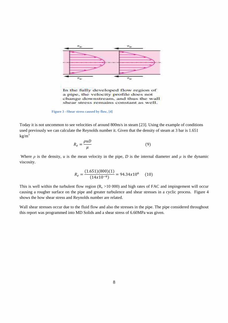
Today it is not uncommon to see velocities of around 800m/s in steam [23]. Using the example of conditions
used previously we can calculate the Reynolds number it. Given that the density of steam at 3 bar is 1.651
kg/m3
Where ρ is the density, u is the mean velocity in the pipe, D is the internal diameter and μ is the dynamic
viscosity.
This is well within the turbulent flow region (Re >10 000) and high rates of FAC and impingement will occur
causing a rougher surface on the pipe and greater turbulence and shear stresses in a cyclic process. Figure 4
shows the how shear stress and Reynolds number are related.
Wall shear stresses occur due to the fluid flow and also the stresses in the pipe. The pipe considered throughout
this report was programmed into MD Solids and a shear stress of 6.60MPa was given.
Figure 3 –Shear stress caused by flow, [4]

9
Figure 4- Reynolds number and shear stress, [22]
Figure 4- Magnetite solubility and pH, [5]
In figure 5 the maximum principal stress is 15.9MPa which is higher than the allowable stress of 13.2MPa. It
would be inside the elastic limit at that temperature. The y-direction stresses have been omitted as they would
correlate to the weight of the pipeline above the considered element, there would also be a pressure drop
ascending the pipeline.
3.5 Geometry
It is far more likely to have greater amounts of FAC corrosion at locations where flow disturbances occur, they
are most likely to occur at “elbows, tight bends, reducer tees, locations downstream of flow control orifices and
valves and fabrication discontinuities [5].” Computational fluid dynamics (CFD) software has allowed
Figure 5 - Mohr’s circle of considered pipeline.

10
different geometries and flow patterns to be analysed with respect to FAC and it has been shown that rates of
corrosion exceed the design corrosion allowance [20]. It is not possible to completely estimate the locations of
FAC however locations where FAC is likely are frequently ultrasonically tested, these locations can also be
accurately guessed using CFD analysis. These locations where FAC has initiated are the areas that need the
most attention as FAC roughens the surface to an orange peel or scallop appearance which induces greater FAC
rates. [5]
4.0 FAC Reduction
4.1 Material choice
Small amounts of chromium added to the steel have dramatic effects on reducing FAC. It has been reported that
rates have been reduced by a factor of 25, this has been achieved by adding 1 to 1.25% chromium to the steel
alloys, although a reduction in FAC has been observed in alloys as low as 0.04% Cr [5]. Chromium addition
increases the hardness of the steel and also the strength, this addition of hardness is induced during the
processing of the steel as the alloys increase the response to the heat treatment. The alloys increase the amount
of hard carbides inside the martensite matrix. It has been noted that chromium builds up in the oxide film and
this reduces its solubility [21].
Molybdenum alloys with Cr-Ni have a reducing effect on FAC rates as they reduce the amount of pitting
corrosion from chlorides and sulphur elements that can get into the steam via the feed water or from cracks in
the boiler tubes. Molybdenum improves the hardness and strength of steel at high temperatures [1]. Pitting
corrosion is often initiated by small surface defects and in steam pipes the cause of these defects could likely be
form momentum transfer of particles in turbulent flow.
4.2 Level of pH
As discussed in section 3.1 the addition of ammonia increases the pH of the steam and this reduces the
solubility of the magnetite layer, thus reduces the wall thinning rates as magnetite forms from the steel pipe, a
graph of this is shown in figure 6. The temperature and pH in a solution are often associated together in a
water-ammonia solution as the temperature rises the pH decreases this is due to the increase in dissociation of
water, releasing more H+
ions. The level of pH and the wear rates can be determined from regions in the
Pourbaix diagrams. It is not yet currently known if other alkalizing agents have the same effect as ammonia
[10].
4.3 Temperature
As stated before the maximum FAC rates occur at around 150ºC however these rates drop as the temperature
increases. Referring to figure 1 for carbon steel an increase in steam temperature to 250ºC reduces FAC rates
by approximately 100 times. Increasing the temperature and pressure to the point where the steam becomes
superheated so there is no water formed on the pipe walls this reduces other form of corrosion such as pitting.

11
4.4 Velocity and Turbulence
In recent computational analyses it has been shown that the velocity is not directly related to FAC rates and that
average flow rates are not a good guide to determine FAC. It has also been shown that there is not a critical
velocity where after FAC rates accelerate. It has been shown that bends in pipes cause turbulence and this
turbulence causes an increase in FAC. The turbulence can be controlled through pipe geometry changes
however it is impractical to change the velocities, temperatures and pressures as this greatly reduces the
efficiency of the plant.
4.5 Pipe Wall Thickness
The most basic way to reduce the effects of FAC and reduce the chance of rupturing is to have piping with a
larger wall thickness. The greater thickness allows for corrosion and wear rates whilst not compromising on the
structural integrity of the system, although the pipes will be heavier and support structures may have to be
reinforced this method may be cheaper than redesigning the pipeline system or changing the steel alloy to NiCr
as it is 10 to 16 times more expensive [18] . The change may mean that a higher pressure steam could be used
increasing the output of the plant.
5.0 Conclusion
FAC has many contributing factors and areas of pipeline are more susceptible than others. FAC once initiated
causes a positive feedback cycle and it is these areas that need to be predicted and frequently tested. There are
methods to reduce FAC however they can be costly or cause greater overall inefficiency. The easiest way to
reduce FAC is to control calculate the pH at temperature of the steam and adjust for this and add it into the feed
water, reducing the loss of magnetite. The formula that has been made to be able to calculate the thickness of
pipe needed for the desired years of service has proven that the corrosion allowance estimated is insufficient.
The reason why FAC gives the magnetite corrosion product in steam pipes has been described and why it
causes high rates of wall thickness reduction due to the environment within the pipe. We have identified the
conditions where FAC is highest and the need to monitor those locations.
6.0 Future Work
Other factors that affect FAC could be further looked into with testing equipment, such as looking at various
temperature and velocity differences on certain grades of steel. If CFD is known then the physical variables of
the steam flow can be changed and different pipe geometries can be looked at and areas where high FAC may
be located and investigated. Boiler tube materials could be looked into and the effects of cracking in them
affect the steam. Detailed stress and strain for various pressures could be looked into and material suggestions
could be given. Research could be done into other alkalizing agents that are put into feed water to see if they
have similar or better corrosion reducing effects than ammonia.

12
References 1) Alloys, C., 2011. Effects of Alloying Elements in Steel. [Online] Available at: http://www.chasealloys.co.uk
[Accessed 27 December 2012].
2) Bardel, E., 2003. Corrosion and Protection. London : Springer.
3) Bhave, M. & Chakraboty, P.L., 2010. Flow accelerated corrosion failures in refineries. Safan , 1, pp.41-44.
4) Cengel, & Turner, R., 2011. Fundamentals of thermal fluid sciences. 4th ed. Reno : McGraw Hill.
5) Dooley , R., 2008. Flow-Accelerated Corrosion in Fossil and Combined Cycle /HSRG Plants. PPChem, pp.78-81.
6) Dooley, R.B. & Chexal , V.K., 2000. Flow-accelerated corrosion of pressure vessels in fossil plants. International
Journal of Pressure Vessels and Piping, 77(2-3), p.87.
7) Electric, G., 1991. Steam Purity. [Online] Available at: http://www.gewater.com [Accessed 26 November 2012].
8) Jonas , & Machemer, , 2008. Steam turbine corrosion and deposits problems and solutions. In Turbomachinery
Symposium. Delaware, 2008. Jonas Inc..
9) Kazutoshi, , Domae, & Yoneda, , 2011. Model of physico-chemical effect on flow accelerated corrosion in power
plant. Elsevier, p.3527.
10) Matthews , , 2010. Impact of pH on the corrosion of cycle. EPRI , pp.7-11.
11) McAllister, E.W., 2005. Pipeline rules of thumb handbook. Oxford: Elsevier.
12) Metals, A.S., 2010. Pressure Rating Tables for Carbon Steel Pipe. [Online] Available at:
http://www.atlassteels.co.nz [Accessed 14 December 2012].
13) Pitkin, L., 2010. Flow Accelerated Corrosion Solutions. [Online] Lucius Pitkin Available at:
www.luciuspitkin.com [Accessed 24 November 2012].
14) Pronyk, C., Cenkowski, S. & Muir, W.E., 2005. Superheated Steam. Winnipeg: CSAE.
15) Raja, A.K. & Dwivedi, , 2006. Power Plant Engineering. New Delhi : New Age Publishing.
16) Robinson, J. & Drews, T., 1999. Resolving Flow-Accelerated Corrosion Problems in the Industiral Steam Plant.
OnePetro, p.3.
17) Sarco, S., 2009. Fluids and Flow. [Online] Available at: http://www.spiraxsarco.com [Accessed 3 January 2012].
18) Selector, C.E., 2005. CES. Granta.
19) Stovall, T.K., 1981. Evaluation of Steam. Tenessee: ORNL.
20) Subramanian, , Madasamy, & Kumawat, H., 2012. Thin layer activation for probing flow accelerated corrosion of
carbon steel. Corrosion Science, 54, p.44.
21) Weignmoon, A., Pearce, J.T. & Chairuangsri, T., 2011. Relationship between microstructure, hardness and
corrosion resistance in 20 wt.%Cr, 27 wt.%Cr and 36 wt.%Cr high chromium cast irons. Materials Chemistry and
Physics, 125(3), p.742.
22) Wharton , J. & Wood, K., 2004. Influence of flow conditions on the corrosion of AISI 304L stainless steel.
Elsevier, pp.533-34.

13
23) Wilcox, B.a., 2007. Boiler Room piping. [Online] Available at: http://www.gutenberg.org [Accessed 17
December 2012].
24) Wranglen, G., 1985. An Introduction to Corrosion and Protection of Metals. New York: Chapman and Hall.
25) Young, C. & Budynas, R.G., 2002. Roark's Formuale for Stress and Strain. 7th ed. New York: McGraw Hill.
Top Related