


Languages
Pages
Legal


Dell Networking S4048–Open Networking (ON) Getting Started Guide
Regulatory Model: E13WRegulatory Type: E13W001

Notes, Cautions, and WarningsNOTE: A NOTE indicates important information that helps you make better use of your computer.
CAUTION: A CAUTION indicates either potential damage to hardware or loss of data and tells you how to avoid the problem.
WARNING: A WARNING indicates a potential for property damage, personal injury, or death.
Copyright © 2014 Dell Inc. All rights reserved. This product is protected by U.S. and international copyright and intellectual property laws. Dell™ and the Dell logo are trademarks of Dell Inc. in the United States and/or other jurisdictions. All other marks and names mentioned herein may be trademarks of their respective companies.
2014 - 12
Rev. A00
1About this GuideThis document is intended as a Getting Started Guide to get new systems up and running and ready for configuration.
For complete installation, configuration, and update information, refer to the following documents at www.dell.com/support:
Table 1. S4048-ON Documents
Information Documentation
Hardware installation and power-up instructions Dell Networking S4048-Open Networking (ON) Installation Guide
Configuration Dell Networking Configuration Guide for the S4048-Open Networking (ON) System
Command line references Dell Networking Command Line Reference Guide for the S4048-Open Networking (ON) System
Latest updates Release Notes for the S4048-ON System
Troubleshooting Dell Open Networking (ON) Troubleshooting Guide
About this Guide 3
2Install the HardwareBefore installing the switch, verify that you meet these guidelines:
• You have enough clearance to the front of the switch so you can read the light emitting diodes (LEDs).
• The AC power cord reaches from the power outlet to the Utility panel connector.
• The switch is rack-mounted before you power it up.
• Cabling is away from sources of electrical noise, such as radios, power lines, and fluorescent lighting. Ensure that the cabling is safely away from other devices that might damage the cables. If needed, allow one rack unit (RU) space between devices to provide room for cabling.
• Airflow around the switch and through the vents is unrestricted.
• Temperature around the unit does not exceed 113°F (45°C). If the switch is in a closed or multirack assembly, the temperature might be higher than normal room temperature.
• Humidity around the switch does not exceed 95 percent.
• Altitude at the installation site is below 10,000 feet.
• The switch is installed in an environment as free as possible from dust and foreign conductive material (such as metal flakes from construction activities). Cooling mechanisms, such as fans and blowers in the switch, can draw dust and other particles causing contaminant buildup inside the chassis, which can result in system malfunction.
Install the ChassisTo install the S4048–Open Networking (ON) system, Dell Networking recommends completing the installation procedures in the order presented here.
NOTE: Always handle the system and its components with care. Avoid dropping the S4048–ON chassis or its field replaceable units.
NOTE: For proper ventilation, position the S4048–ON chassis in an equipment rack (or cabinet) with a minimum of 5 inches (12.7 cm) of clearance around exhaust vents. The acceptable ambient temperature ranges are listed in the Technical Specifications section under Environmental Parameters.
CAUTION: Always wear an electrostatic discharge (ESD)-preventive wrist or heel ground strap when handling the S4048–ON and its components. As with all electrical devices of this type, take all necessary safety precautions to prevent injury when installing this system. ESD damage can occur if components are mishandled.
CAUTION: The S4048–ON contains two power cords. Disconnect both power cords before servicing.
CAUTION: Only trained and qualified personnel should install this equipment. Read this guide before installing and powering up the S4048–ON.
4 Install the Hardware
Rack Mounting Safety Considerations
• Rack mounting — You may either place the switch on a rack shelf or mount the switch directly into a 19" wide, EIA-310-E- compliant rack.
• Rack loading — Overloading or uneven loading of racks may result in shelf or rack failure, which may damage the equipment and cause personal injury. Stabilize the racks in a permanent location before loading begins. Mount the components beginning at the bottom of the rack, then work to the top. Do not exceed your rack load rating.
• Power considerations — Connect only to the power source specified on the unit. When you install multiple electrical components in a rack, ensure that the total component power ratings do not exceed the circuit capabilities. Overloaded power sources and extension cords present fire and shock hazards.
• Elevated ambient temperature — If you install the equipment in a closed rack assembly, the operating temperature of the rack environment may be greater than the room ambient temperature. Use care not to exceed the 45°C maximum ambient temperature of the switch.
• Reduced air flow — Install the equipment in the rack so that you do not compromise the amount of airflow required for safe operation of the equipment.
• Reverse air flow — To ensure cool air intake and to avoid hot air blow out from the I/O panel, ensure that you have the necessary clearance.
• Reliable earthing — Maintain reliable earthing of rack-mounted equipment. Pay particular attention to the supply connections other than the direct connections to the branch circuit; for example, the use of the power strips.
• Do not mount the equipment with the Utility panel facing in the downward position.
NOTE: These instructions are a condensed reference. Read the safety instructions in your Safety, Environmental, and Regulatory information booklet before you begin.
NOTE: The illustrations in this document are not intended to represent a specific switch.
Rack Mount the SwitchYou may either place the switch on a rack shelf or mount the switch directly into a 19" wide, EIA-310-E-compliant rack (four-post, two-post, or threaded methods).
The Dell ReadyRails™ system is provided for 1U front-rack and two-post installations. The ReadyRails system includes two separately packaged rail assemblies and two rails that are shipped attached to the sides of the switch.
WARNING: This is a condensed reference. Read the safety instructions in your Safety, Environmental, and Regulatory information booklet before you begin.
CAUTION: Do not use the mounted Ready-Rails as a shelf or a workplace.
NOTE: The illustrations in this document are not intended to represent a specific switch.
Install the Hardware 5
Installing the Dell ReadyRails SystemThe ReadyRails rack mounting system is provided to easily configure your rack so that you can install your switch.
Install the ReadyRails system using the 1U tool-less method or one of three possible 1U tooled methods (two-post flush mount, two-post center mount, or four-post threaded).
1U Tool-less Configuration (Four-Post Square Hole or Unthreaded Round Hole)
To install the Dell ReadyRails system using the 1U tool-less configuration, follow these steps.
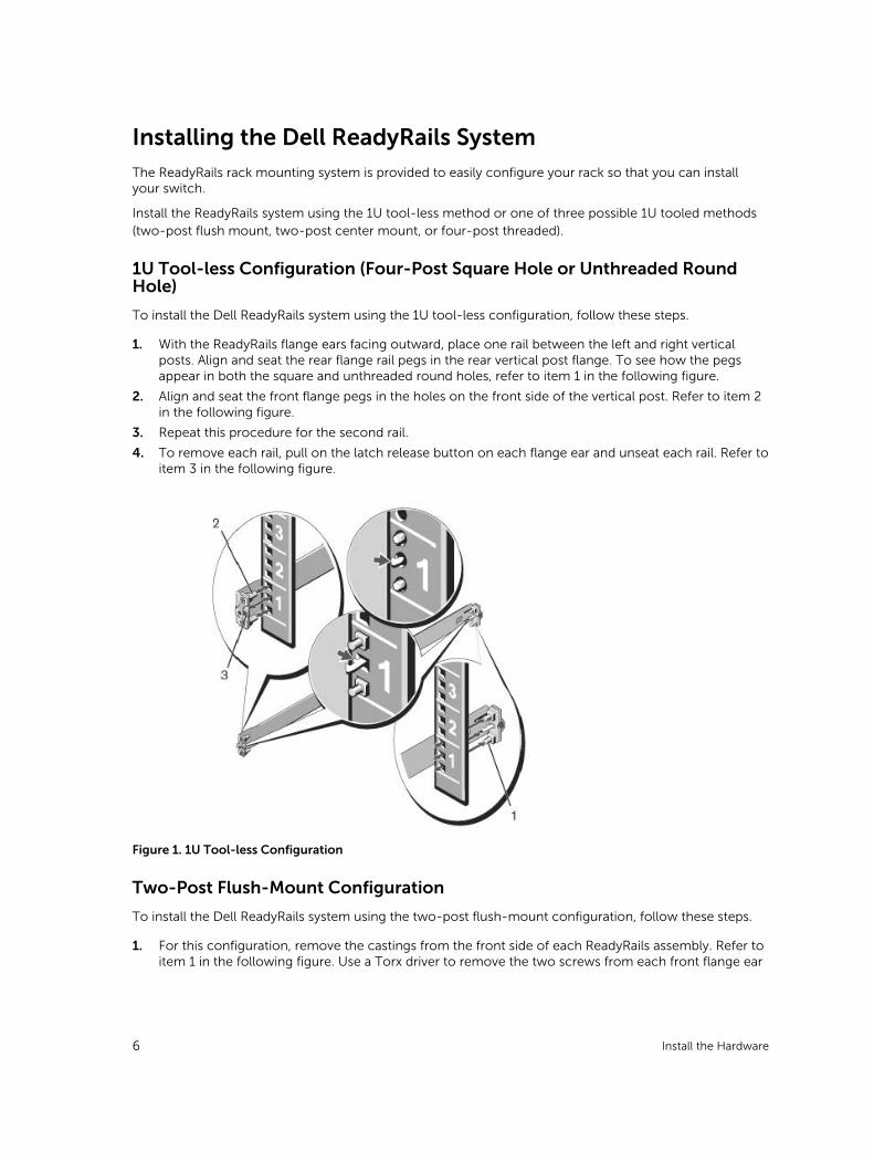
1. With the ReadyRails flange ears facing outward, place one rail between the left and right vertical posts. Align and seat the rear flange rail pegs in the rear vertical post flange. To see how the pegs appear in both the square and unthreaded round holes, refer to item 1 in the following figure.
2. Align and seat the front flange pegs in the holes on the front side of the vertical post. Refer to item 2 in the following figure.
3. Repeat this procedure for the second rail.
4. To remove each rail, pull on the latch release button on each flange ear and unseat each rail. Refer to item 3 in the following figure.
Figure 1. 1U Tool-less Configuration
Two-Post Flush-Mount Configuration
To install the Dell ReadyRails system using the two-post flush-mount configuration, follow these steps.
1. For this configuration, remove the castings from the front side of each ReadyRails assembly. Refer to item 1 in the following figure. Use a Torx driver to remove the two screws from each front flange ear
6 Install the Hardware
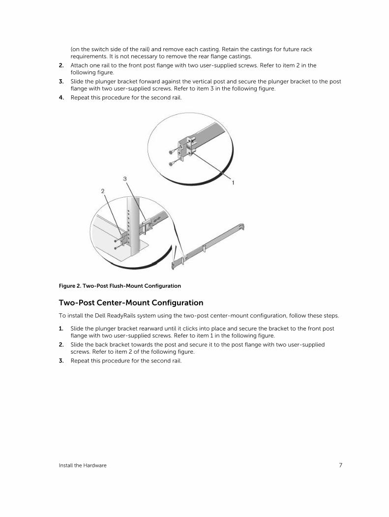
(on the switch side of the rail) and remove each casting. Retain the castings for future rack requirements. It is not necessary to remove the rear flange castings.
2. Attach one rail to the front post flange with two user-supplied screws. Refer to item 2 in the following figure.
3. Slide the plunger bracket forward against the vertical post and secure the plunger bracket to the post flange with two user-supplied screws. Refer to item 3 in the following figure.
4. Repeat this procedure for the second rail.
Figure 2. Two-Post Flush-Mount Configuration
Two-Post Center-Mount Configuration
To install the Dell ReadyRails system using the two-post center-mount configuration, follow these steps.
1. Slide the plunger bracket rearward until it clicks into place and secure the bracket to the front post flange with two user-supplied screws. Refer to item 1 in the following figure.
2. Slide the back bracket towards the post and secure it to the post flange with two user-supplied screws. Refer to item 2 of the following figure.
3. Repeat this procedure for the second rail.
Install the Hardware 7
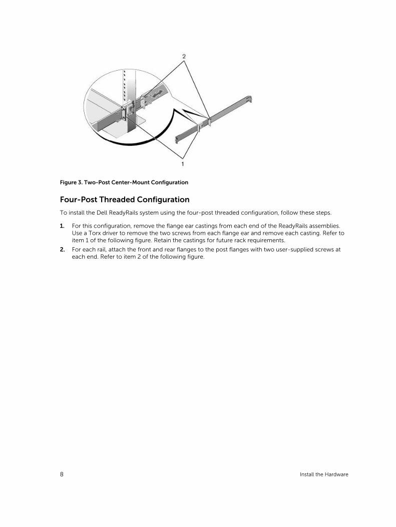
Figure 3. Two-Post Center-Mount Configuration
Four-Post Threaded Configuration
To install the Dell ReadyRails system using the four-post threaded configuration, follow these steps.
1. For this configuration, remove the flange ear castings from each end of the ReadyRails assemblies. Use a Torx driver to remove the two screws from each flange ear and remove each casting. Refer to item 1 of the following figure. Retain the castings for future rack requirements.
2. For each rail, attach the front and rear flanges to the post flanges with two user-supplied screws at each end. Refer to item 2 of the following figure.
8 Install the Hardware
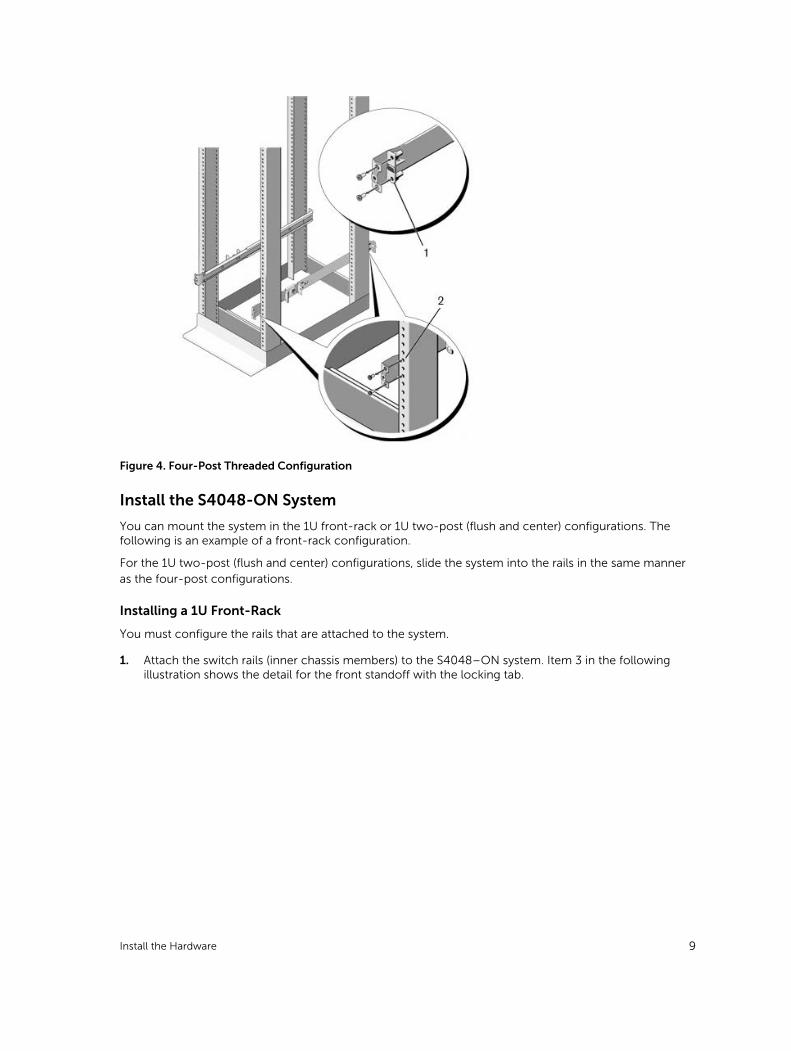
Figure 4. Four-Post Threaded Configuration
Install the S4048-ON System
You can mount the system in the 1U front-rack or 1U two-post (flush and center) configurations. The following is an example of a front-rack configuration.
For the 1U two-post (flush and center) configurations, slide the system into the rails in the same manner as the four-post configurations.
Installing a 1U Front-Rack
You must configure the rails that are attached to the system.
1. Attach the switch rails (inner chassis members) to the S4048–ON system. Item 3 in the following illustration shows the detail for the front standoff with the locking tab.
Install the Hardware 9
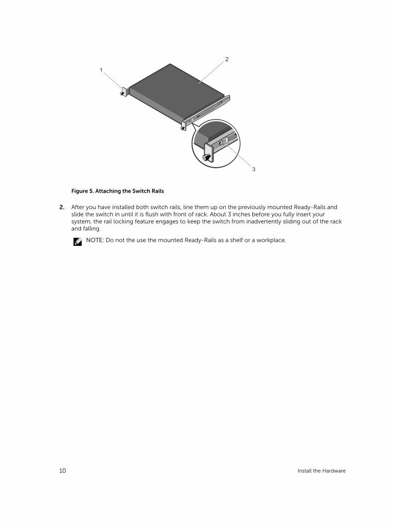
Figure 5. Attaching the Switch Rails
2. After you have installed both switch rails, line them up on the previously mounted Ready-Rails and slide the switch in until it is flush with front of rack. About 3 inches before you fully insert your system, the rail locking feature engages to keep the switch from inadvertently sliding out of the rack and falling.
NOTE: Do not the use the mounted Ready-Rails as a shelf or a workplace.
10 Install the Hardware
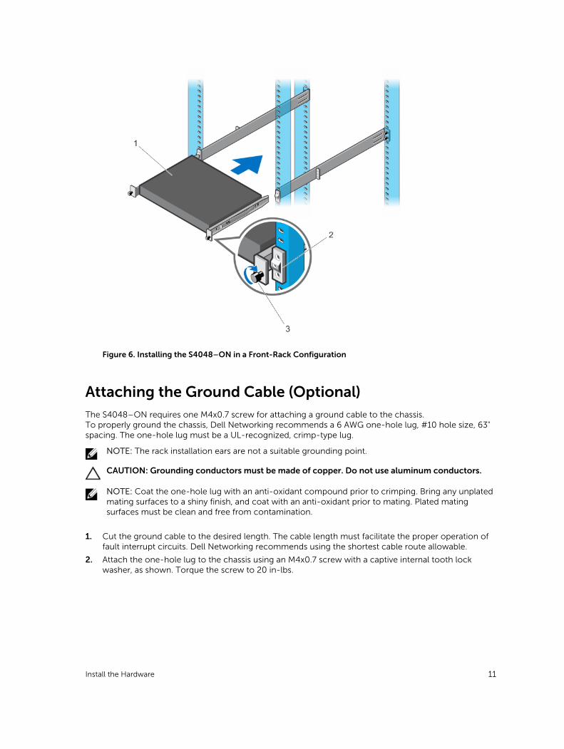
Figure 6. Installing the S4048–ON in a Front-Rack Configuration
Attaching the Ground Cable (Optional)The S4048–ON requires one M4x0.7 screw for attaching a ground cable to the chassis.To properly ground the chassis, Dell Networking recommends a 6 AWG one-hole lug, #10 hole size, 63" spacing. The one-hole lug must be a UL-recognized, crimp-type lug.
NOTE: The rack installation ears are not a suitable grounding point.
CAUTION: Grounding conductors must be made of copper. Do not use aluminum conductors.
NOTE: Coat the one-hole lug with an anti-oxidant compound prior to crimping. Bring any unplated mating surfaces to a shiny finish, and coat with an anti-oxidant prior to mating. Plated mating surfaces must be clean and free from contamination.
1. Cut the ground cable to the desired length. The cable length must facilitate the proper operation of fault interrupt circuits. Dell Networking recommends using the shortest cable route allowable.
2. Attach the one-hole lug to the chassis using an M4x0.7 screw with a captive internal tooth lock washer, as shown. Torque the screw to 20 in-lbs.
Install the Hardware 11
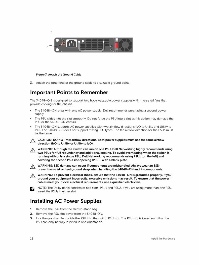
Figure 7. Attach the Ground Cable
3. Attach the other end of the ground cable to a suitable ground point.
Important Points to RememberThe S4048–ON is designed to support two hot-swappable power supplies with integrated fans that provide cooling for the chassis.
• The S4048–ON ships with one AC power supply. Dell recommends purchasing a second power supply.
• The PSU slides into the slot smoothly. Do not force the PSU into a slot as this action may damage the PSU or the S4048-ON chassis.
• The S4048–ON supports AC power supplies with two air-flow directions (I/O to Utility and Utility to I/O). The S4048–ON does not support mixing PSU types. The fan airflow direction for the PSUs must be the same.
CAUTION: DO NOT mix airflow directions. Both power supplies must use the same airflow direction (I/O to Utility or Utility to I/O).
WARNING: Although the switch can run on one PSU, Dell Networking highly recommends using two PSUs for full redundancy and additional cooling. To avoid overheating when the switch is running with only a single PSU, Dell Networking recommends using PSU1 (on the left) and covering the second PSU slot opening (PSU2) with a blank plate.
WARNING: ESD damage can occur if components are mishandled. Always wear an ESD-preventive wrist or heel ground strap when handling the S4048–ON and its components.
WARNING: To prevent electrical shock, ensure that the S4048–ON is grounded properly. If you ground your equipment incorrectly, excessive emissions may result. To ensure that the power cables meet your local electrical requirements, use a qualified electrician.
NOTE: The Utility panel consists of two slots, PSU1 and PSU2. If you are using more than one PSU, insert the PSUs in either slot.
Installing AC Power Supplies1. Remove the PSU from the electro-static bag.
2. Remove the PSU slot cover from the S4048-ON.
3. Use the grab handle to slide the PSU into the switch PSU slot. The PSU slot is keyed such that the PSU can only be fully inserted in one orientation.
12 Install the Hardware
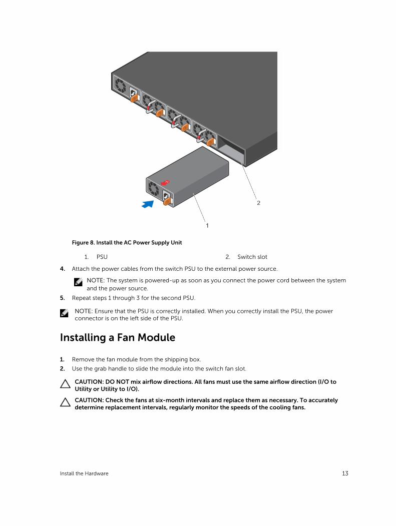
Figure 8. Install the AC Power Supply Unit
1. PSU 2. Switch slot
4. Attach the power cables from the switch PSU to the external power source.
NOTE: The system is powered-up as soon as you connect the power cord between the system and the power source.
5. Repeat steps 1 through 3 for the second PSU.
NOTE: Ensure that the PSU is correctly installed. When you correctly install the PSU, the power connector is on the left side of the PSU.
Installing a Fan Module
1. Remove the fan module from the shipping box.
2. Use the grab handle to slide the module into the switch fan slot.
CAUTION: DO NOT mix airflow directions. All fans must use the same airflow direction (I/O to Utility or Utility to I/O).
CAUTION: Check the fans at six-month intervals and replace them as necessary. To accurately determine replacement intervals, regularly monitor the speeds of the cooling fans.
Install the Hardware 13
Installing the SFP+ and QSFP+ OpticsThe S4048–ON has 48 small form-factor pluggable plus (SFP+) optical ports and six quad small form-factor pluggable plus (QSFP+) optical ports.For a list of supported optics, refer to the S4048–ON data sheet at www.dell.com or contact your Dell Networking representative.
CAUTION: ESD damage can occur if the components are mishandled. Always wear an ESD-preventive wrist or heel ground strap when handling the S4048–ON and its components.
WARNING: When working with optical fibers, follow all the warning labels and always wear eye protection. Never look directly into the end of a terminated or unterminated fiber or connector as it may cause eye damage.
1. Position the optic so it is in the correct position. The optic has a key that prevents it from being inserted incorrectly.
2. Insert the optic into the port until it gently snaps into place.
NOTE: Both rows of QSFP+ ports require that you install the 40 GbE optics with the tabs facing up.
NOTE: When you cable the ports, be sure not to interfere with the airflow from the small vent holes above and below the ports.
Supply Power and Power Up the SystemSupply power to the S4048–ON after the chassis is mounted in a rack or cabinet.
Dell Networking recommends re-inspecting your system prior to powering up. Verify that:
• The equipment is properly secured to the rack.
• The equipment rack is properly mounted and grounded.
• The ambient temperature around the unit (which may be higher than the room temperature) is within the limits specified for the S4048–ON.
• There is sufficient airflow around the unit.
• The input circuits are correctly sized for the loads and that you use sufficient overcurrent protection devices.
• All protective covers are in place.
NOTE: A country/region-specific AC power cable is included in the shipping container for powering up an AC power supply. You must order all other power cables separately.
CAUTION: ESD damage can occur if the components are mishandled. Always wear an ESD-preventive wrist or heel ground strap when handling the S4048–ON and its components.
When the system powers up, the fans come on at high speed. The fan speed slows as the system boots up. The power status LED blinks until the boot-up sequence is complete. When the boot up is complete, the power status LED is steadily lit.
AC Power
CAUTION: Ensure that the PSU is installed correctly. The AC power connector must be on the left side of the PSU and the status LED at the top of the PSU.
14 Install the Hardware
Connect the plug to each AC power connector. Make sure that the power cord is secure.
As soon as the cable is connected between the S4048–ON and the power source, the switch is powered-up; there is no on/off switch.
Fans
The three fan modules and the power supplies are hot-swappable if you install a second (redundant) power supply.
NOTE: To run the system, the three fan slots must have operating fan units. If you do not install a module in each slot, the system shuts down in one minute.
NOTE: The S4048–ON supports two airflow direction options. You can only use a single direction in a chassis; do not mix fan flow types.
• Normal is airflow from the I/O panel to the power supply.
• Reversed is airflow from the power supply to the I/O panel.
There are environmental factors that could decrease the amount of time required between fan replacements. Check these environmental factors regularly. Any unusual environmental circumstance at the site that causes an increase in temperature and/or particulate matter in the air might affect performance (for example, new equipment installation).
After Installing the S4048–ON
After you have securely installed and powered on the S4048-ON, to configure your system, refer to your ONIE-compatible operating system documentation.
Install the Hardware 15
3Dell Networking OSTo initially configure the Dell Networking operating system (OS), use the following sections.
NOTE: This chapter applies ONLY if you already have the Dell Networking OS installed on your system from the factory. If you are installing a third-party OS, refer to your third-party OS documentation.
NOTE: For complete installation and configuration information, refer to the following documents at www.dell.com/support:
• Dell Networking Installation Guide for the S4048–Open Networking (ON) System.
• Dell Networking Command Line Reference Guide for the S4048–Open Networking (ON) System.
• Dell Networking Configuration Guide for the S4048–Open Networking (ON) System.
• Dell Networking Release Notes for the S4048–Open Networking (ON) System.
Enter the Initial Configuration InformationTo set up the switch, assign an IP address and other configuration information necessary for the switch to communicate with the local routers and the Internet. The minimal configuration provided here does not cover most of the features; it simply allows you to perform other configuration tasks using a Telnet connection from your management network.
NOTE: To configure other features and interfaces, refer to the Dell Networking OS Configuration Guide for the S4048 System.
IP Settings
To set up the switch, get the following information from your network administrator:
• Switch IP address
• Subnet mask (IP netmask)
• Default gateway (router)
• Enable secret password
• Enable password
• Telnet password
16 Dell Networking OS

Navigating CLI ModesThe Dell Networking OS prompt changes to indicate the CLI mode.
You must move linearly through the command modes, except for the end command which takes you
directly to EXEC Privilege mode and the exit command which moves you up one command mode level.
Accessing the ConsoleThe RS-232 console port is on the right-hand side of the S4048–ON system as you face the PSU side of the chassis, as shown in the following illustration.
Figure 9. S4048–ON RS-232 Console Port
1. RJ-45 Management Port
2. RS-232 Console Port
NOTE: You must have a password configured on a virtual terminal line before you can Telnet into the S4048–ON system. Therefore, use a console connection when connecting to the system for the first time. Before starting this procedure, be sure that you have a terminal emulation program already installed on your PC.
1. Install an RJ-45 copper cable into the console port. Use a rollover cable to connect the S4048–ON console port to a terminal server.
2. Connect the other end of the cable to the DTE terminal server.
3. Set the default terminal settings as follows.
• 115200 baud rate (set the MicroUSB console port to 9600 baud rate)
• No parity
• 8 data bits
• 1 stop bit
• No flow control
Accessing the RJ-45 Console Port with a DB-9 Adapter
You can connect to the console using an RJ-45 to RJ-45 rollover cable and an RJ-45 to DB-9 female DTE adapter to a terminal server (for example, a PC).
The pin assignments between the console and a DTE terminal server are as follows:
Dell Networking OS 17
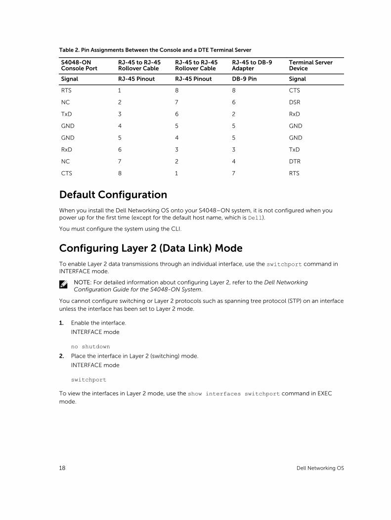
Table 2. Pin Assignments Between the Console and a DTE Terminal Server
S4048-ON Console Port
RJ-45 to RJ-45 Rollover Cable
RJ-45 to RJ-45 Rollover Cable
RJ-45 to DB-9 Adapter
Terminal Server Device
Signal RJ-45 Pinout RJ-45 Pinout DB-9 Pin Signal
RTS 1 8 8 CTS
NC 2 7 6 DSR
TxD 3 6 2 RxD
GND 4 5 5 GND
GND 5 4 5 GND
RxD 6 3 3 TxD
NC 7 2 4 DTR
CTS 8 1 7 RTS
Default ConfigurationWhen you install the Dell Networking OS onto your S4048–ON system, it is not configured when you power up for the first time (except for the default host name, which is Dell).
You must configure the system using the CLI.
Configuring Layer 2 (Data Link) ModeTo enable Layer 2 data transmissions through an individual interface, use the switchport command in INTERFACE mode.
NOTE: For detailed information about configuring Layer 2, refer to the Dell Networking Configuration Guide for the S4048-ON System.
You cannot configure switching or Layer 2 protocols such as spanning tree protocol (STP) on an interface unless the interface has been set to Layer 2 mode.
1. Enable the interface.
INTERFACE mode
no shutdown2. Place the interface in Layer 2 (switching) mode.
INTERFACE mode
switchport
To view the interfaces in Layer 2 mode, use the show interfaces switchport command in EXEC
mode.
18 Dell Networking OS
Configuring a Host NameThe host name appears in the prompt. The default host name is Dell.
Host names must start with a letter, end with a letter or digit, and must have characters, letters, digits, and hyphens in the string.
• Create a new host name.
CONFIGURATION mode
hostname name
Accessing the System RemotelyYou can configure the S4048–ON system to be accessed remotely by Telnet.
The system has a dedicated management port and a management routing table that is separate from the IP routing table.
1. Configure an IP address for the management port (Configuring the Management Port IP Address).
2. Configure a management route with a default gateway (Configuring the Management Route).
3. Configure a username and password (Configuring the Username and Password).
Configuring the Management Port IP Address
In order to access the system remotely, assign IP addresses to the management ports.
1. Enter INTERFACE mode for the Management port.
CONFIGURATION mode
interface ManagementEthernet slot/port2. Assign an IP address to the interface.
INTERFACE mode
ip address ip-address/mask3. Enable the interface.
INTERFACE mode
no shutdown
Configuring the Management Route
Define a path from the S4048–ON to the network from which you are accessing the S4048–ON remotely.Management routes are separate from IP routes and are used to manage the S4048–ON through the management port.
• Configure a management route to the network from which you are accessing the system.
CONFIGURATION mode
management route ip-address/mask gateway
Dell Networking OS 19
Configuring the Username and Password
To access the system remotely, configure a system username and password.
• Configure a username and password to access the system remotely.
CONFIGURATION mode
username username password [encryption-type]
Configuring the Enable PasswordAccess EXEC Privilege mode using the enable command. EXEC Privilege mode is unrestricted by default.
As a basic security measure, configure a password. There are two types of enable passwords:
• enable password — stores the password in the running/startup configuration using a data encryption standard (DES)-encryption method.
• enable secret — stores the password in the running/startup configuration using a stronger, MD5-encryption method.
Dell Networking recommends using the enable secret password.
• Create a password to access EXEC Privilege mode.
CONFIGURATION mode
enable [password | secret] [level level] [encryption-type] password
Creating a Port-based VLANThe default VLAN (VLAN 1) is part of the system startup configuration and does not require configuration.
To configure a port-based VLAN, create the VLAN and then add physical interfaces or port channel (LAG) interfaces to the VLAN.
• Configure a port-based VLAN (if the vlan-id is different from the Default VLAN ID) and enter INTERFACE VLAN mode.
CONFIGURATION mode
interface vlan vlan-id
After you create a VLAN, assign interfaces in Layer 2 mode to the VLAN to activate the VLAN.
To view the configured VLANs, use the show vlan command in EXEC Privilege mode.
Assigning Interfaces to a VLAN
You can only assign interfaces in Layer 2 mode to a VLAN using the tagged and untagged commands.
To place an interface in Layer 2 mode, use the switchport command.
You can designate Layer 2 interfaces as tagged or untagged. When you place an interface in Layer 2 mode using the switchport command, the interface automatically designates untagged and is in the
Default VLAN.
20 Dell Networking OS
To tag frames leaving an interface in Layer 2 mode, assign that interface as tagged to a port-based VLAN to tag it with that VLAN ID.
To move untagged interfaces from the Default VLAN to another VLAN, use the untagged command.
1. Tag interfaces. Access INTERFACE VLAN mode of the VLAN to which you want to assign the interface.
CONFIGURATION mode
interface vlan vlan-id2. Enable an interface to include the IEEE 802.1Q tag header.
INTERFACE mode
tagged interface
This command is available only in VLAN interfaces.
3. Move untagged interfaces. Access INTERFACE VLAN mode of the VLAN to which you want to assign the interface.
CONFIGURATION mode
interface vlan vlan-id4. Configure an interface as untagged.
INTERFACE mode
untagged interface
This command is available only in VLAN interfaces.
To view which interfaces are tagged or untagged and to view which VLAN the interfaces belong, use the show vlan command. To view just the interfaces that are in Layer 2 mode, use the show interfaces switchport command in EXEC Privilege mode or EXEC mode.
Assigning an IP Address to a VLAN
VLANs are a Layer 2 feature. For two physical interfaces on different VLANs to communicate, assign an IP address to the VLANs to route traffic between the two interfaces.
The shutdown command in INTERFACE mode for a VLAN does not affect Layer 2 traffic on the VLAN.
NOTE: You cannot assign an IP address to the Default VLAN, which, by default, is VLAN 1. To assign another VLAN ID to the Default VLAN, use the default vlan-id vlan-id command from the configuration mode.
• Access INTERFACE VLAN mode of the VLAN to which you want to assign the IP address then configure an IP addresses and mask on the interface.
INTERFACE mode
ip address ip-address mask [secondary]
Dell Networking OS 21

Connect the S4048–ON to the NetworkAfter you have completed the hardware installation and software configuration for the S4048–ON system, connect to your company network by following your company’s cabling requirements.
22 Dell Networking OS
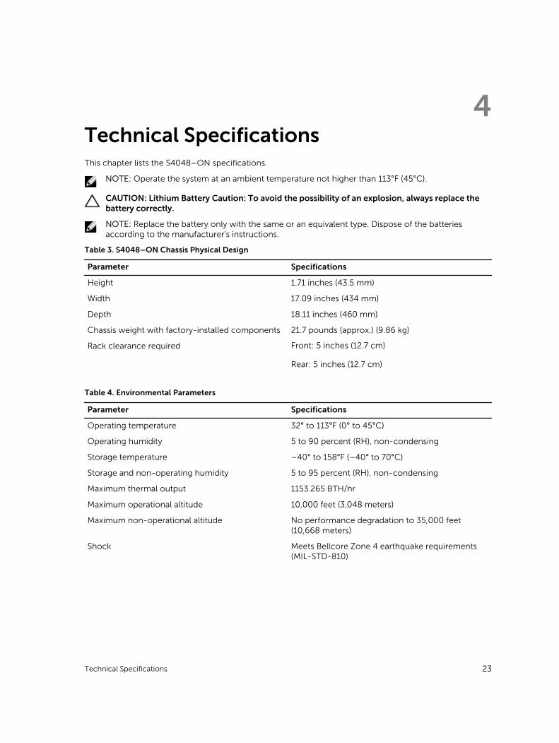
4Technical SpecificationsThis chapter lists the S4048–ON specifications.
NOTE: Operate the system at an ambient temperature not higher than 113°F (45°C).
CAUTION: Lithium Battery Caution: To avoid the possibility of an explosion, always replace the battery correctly.
NOTE: Replace the battery only with the same or an equivalent type. Dispose of the batteries according to the manufacturer's instructions.
Table 3. S4048–ON Chassis Physical Design
Parameter Specifications
Height 1.71 inches (43.5 mm)
Width 17.09 inches (434 mm)
Depth 18.11 inches (460 mm)
Chassis weight with factory-installed components 21.7 pounds (approx.) (9.86 kg)
Rack clearance required Front: 5 inches (12.7 cm)
Rear: 5 inches (12.7 cm)
Table 4. Environmental Parameters
Parameter Specifications
Operating temperature 32° to 113°F (0° to 45°C)
Operating humidity 5 to 90 percent (RH), non-condensing
Storage temperature –40° to 158°F (–40° to 70°C)
Storage and non-operating humidity 5 to 95 percent (RH), non-condensing
Maximum thermal output 1153.265 BTH/hr
Maximum operational altitude 10,000 feet (3,048 meters)
Maximum non-operational altitude No performance degradation to 35,000 feet (10,668 meters)
Shock Meets Bellcore Zone 4 earthquake requirements (MIL-STD-810)
Technical Specifications 23
Top Related