


Languages
Pages
Legal

© Danfoss | 2017.07 VD.C6.X6.02 | 1
Combined automatic balancing valveAB-PM – valve DN 10-32, PN 16
Data sheet
Description AB-PM is a combined automatic balancing valve. It features three function in compact valve body:1. Differential pressure controller2. Control valve with linear characteristic3. Flow limiter
Benefits:• Reliable heating system resulting in:
- proper heat distribution even at partial loads- noise free operation based on stable low
Δp over thermostatic radiator valves even in installation where higher pump head is needed
• Lower heating cost• Better indoor temperature control • Faster in simpler installation with less
installation space needed
Ordering AB-PM valve (including 1.5 m impulse tube and imp. tube adapter)
Picture DN Ext. thread(ISO 228/1) Code No.
10G ½ A
003Z1401
10 HP 003Z1411
15G ¾ A
003Z1402
15 HP 003Z1412
20G 1 A
003Z1403
20 HP 003Z1413
25G 1¼ A
003Z1404
25 HP 003Z1414
32G 1½ A
003Z1405
32 HP 003Z1415
ActuatorType Power supply Cable length Code No.
TWA-Z NO 1)24 V AC
1.2 m082F1260
230 V AC 082F1264
TWA-Z NC 1)24 V AC
1.2 m082F1262
230 V AC 082F1266
ABN A5 NO24 V AC
not included 2)
082F1151
230 V AC 082F1153
ABN A5 NC24 V AC 082F1150
230 V AC 082F1152
1) up to 60 % of Qmax on AB-PM DN 25 and DN 322) For cable code numbers see datasheet ABN A5.
AccessoriesType To pipe To valve Code No.
Tailpiece threaded (1 pcs.)
R 3/8 DN 10 003Z0231
R 1/2 DN 15 003Z0232
R 3/4 DN 20 003Z0233
R 1 DN 25 003Z0234
R 11/4 DN 32 003Z0235
Tailpiece welding (1 pcs.)
DN 15 003Z0226
DN 20 003Z0227
DN 25 003Z0228
DN 32 003Z0229
Tailpiece for soldering (2 nuts, 2 gaskets, 2 soldering plugs)
DN 10 003Z7016
DN 15 003Z7017
Stroke limiter - TWA (5 pcs. in a bag) 1) 003Z1237
1) Stroke limiter ensures min. 5% opening of AB-PM when TWA-Z is closed.
Spare partsType Remark Code No.
Impulse tube adapter
3/8” - 1/16” 003L5042
¾” - 1/16” 003Z0109
¼” - 1/16” 003L8151
Impulse tube with O-rings1.5 m 003L8152
2.5 m 003Z0690
Shut-off knob (red) 003Z0250
Room controllerType Power supply Cable length Code No.
RC-T2 230 V AC Thermostat 2- pipe 193B0941
Data sheet AB-PM valve, PN 16
2 | VD.C6.X6.02 © Danfoss | 2017.07
Technical data Nominal diameter DN 10 10 HP 15 15 HP 20 20 HP 25 25 HP 32 32 HP
Qnom (at 100% setting) l/h 110 300 600 1200 2300
Max. pressure at zero load
kPa
22 35 22 35 22 35 22 35 22 35
Max. differential pressure (Δpa) 400
Min. differential pressure (Δpa) 18 28 18 28 18 28 18 28 18 28
Nominal maximal pressure bar 16 (PN16)
Control valves characteristic Linear
Shut-off leakage rate Acc. to ISO 5208 class A - no visible leakage
Medium temperature °C −10 … +120
CV stroke mm 2.25 4.5
Connection Ext. thread ISO 228/1 G 1/2 A G ¾ A G 1 A G 1¼ A G 11/2 A
Actuator M 30 × 1.5
Materials in water
Valve body DZR Brass (CuZn36Pb2As - CW 602N)
Membrane and O-ring EPDM
Spring W.Nr. 1.4568, W.Nr. 1.4310
Cone (PC) W.Nr. 1.4305
Seat (PC) EPDM
Cone (CV) CuZn40Pb3 - CW 614N
Seat (CV) DZR Brass (CuZn36Pb2As - CW 602N)
Flat gasket NBR
Screw Stainless Steel (A2)
Sealing agent Dimethacrylate Ester
Materials out of the water
Plastic parts PA
Insert parts and outer screws CuZn39Pb3 - CW 614N; W.Nr. 1.4310; W.Nr. 1.4401
Material connection sets
Ball valve Brass (CW614N)
Pipe Steel (P235GH)
Gasket PTFE
Sealing agent: Connection AFM34
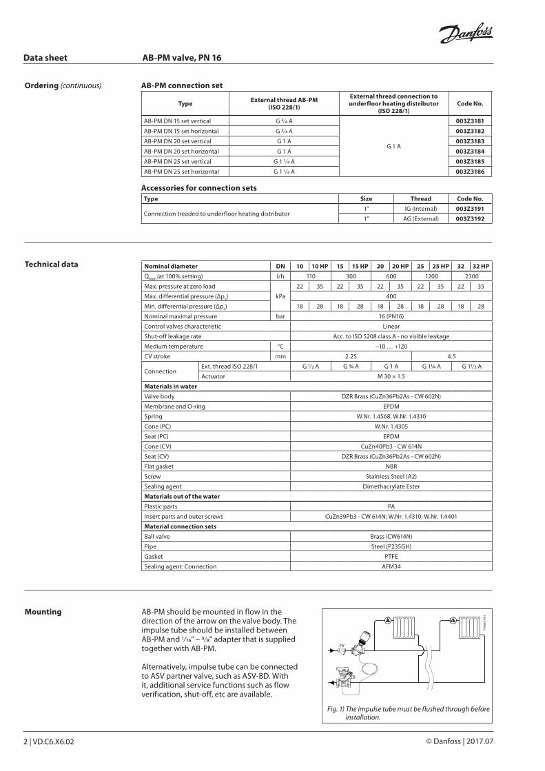
Mounting AB-PM should be mounted in flow in the direction of the arrow on the valve body. The impulse tube should be installed between AB-PM and 1/16” – 3/8” adapter that is supplied together with AB-PM.
Alternatively, impulse tube can be connected to ASV partner valve, such as ASV-BD. With it, additional service functions such as flow verification, shut-off, etc are available.
Fig. 1) The impulse tube must be flushed through before installation.
Ordering (continuous) AB-PM connection set
Type External thread AB-PM (ISO 228/1)
External thread connection to underfloor heating distributor
(ISO 228/1)Code No.
AB-PM DN 15 set vertical G 3/4 A
G 1 A
003Z3181
AB-PM DN 15 set horizontal G 3/4 A 003Z3182
AB-PM DN 20 set vertical G 1 A 003Z3183
AB-PM DN 20 set horizontal G 1 A 003Z3184
AB-PM DN 25 set vertical G 1 1/4 A 003Z3185
AB-PM DN 25 set horizontal G 1 1/4 A 003Z3186
Accessories for connection setsType Size Thread Code No.
Connection treaded to underfloor heating distributor 1” IG (Internal) 003Z3191
1” AG (External) 003Z3192
Data sheet AB-PM valve, PN 16
VD.C6.X6.02 | 3© Danfoss | 2017.07
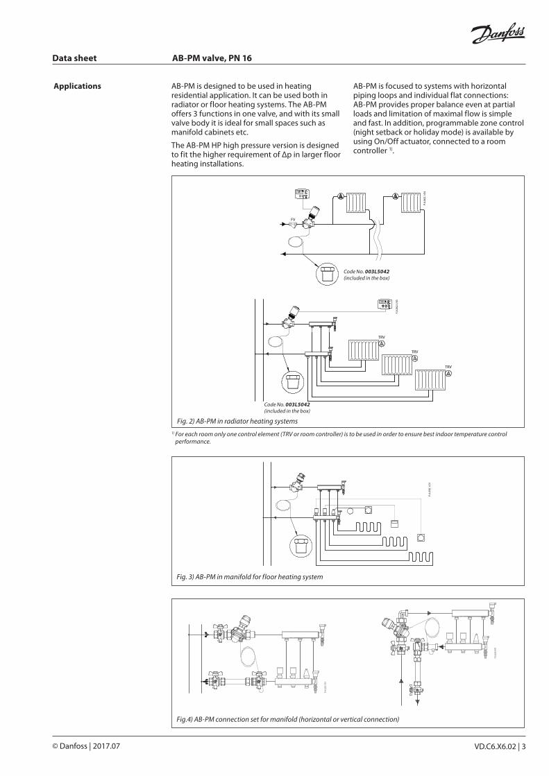
1) For each room only one control element (TRV or room controller) is to be used in order to ensure best indoor temperature control performance.
Code No. 003L5042 (included in the box)
Code No. 003L5042 (included in the box)
Applications AB-PM is designed to be used in heating residential application. It can be used both in radiator or floor heating systems. The AB-PM offers 3 functions in one valve, and with its small valve body it is ideal for small spaces such as manifold cabinets etc.
The AB-PM HP high pressure version is designed to fit the higher requirement of Δp in larger floor heating installations.
Fig. 2) AB-PM in radiator heating systems
AB-PM is focused to systems with horizontal piping loops and individual flat connections:AB-PM provides proper balance even at partial loads and limitation of maximal flow is simple and fast. In addition, programmable zone control (night setback or holiday mode) is available by using On/Off actuator, connected to a room controller 1).
Fig. 3) AB-PM in manifold for f loor heating system
Fig.4) AB-PM connection set for manifold (horizontal or vertical connection)
Data sheet AB-PM valve, PN 16
4 | VD.C6.X6.02 © Danfoss | 2017.07
DN 10
∆pr [kPa]
flow
[l/h
]
20 %
30 %
40 %
50 %
60 %
70 %
90 %
100 %
80 %
DN 10 HP
∆pr [kPa]
flow
[l/h
]
20 %
30 %
40 %
50 %
60 %
90 %
100 %
80 %
70 %
DN 15
∆pr [kPa]
flow
[l/h
]
20 %
30 %
40 %
50 %
60 %
70 %
90 %
100 %
80 %
DN 15 HP
∆pr [kPa]
flow
[l/h
]
20 %
30 %
40 %
50 %
60 %
90 %
100 %
80 %
70 %
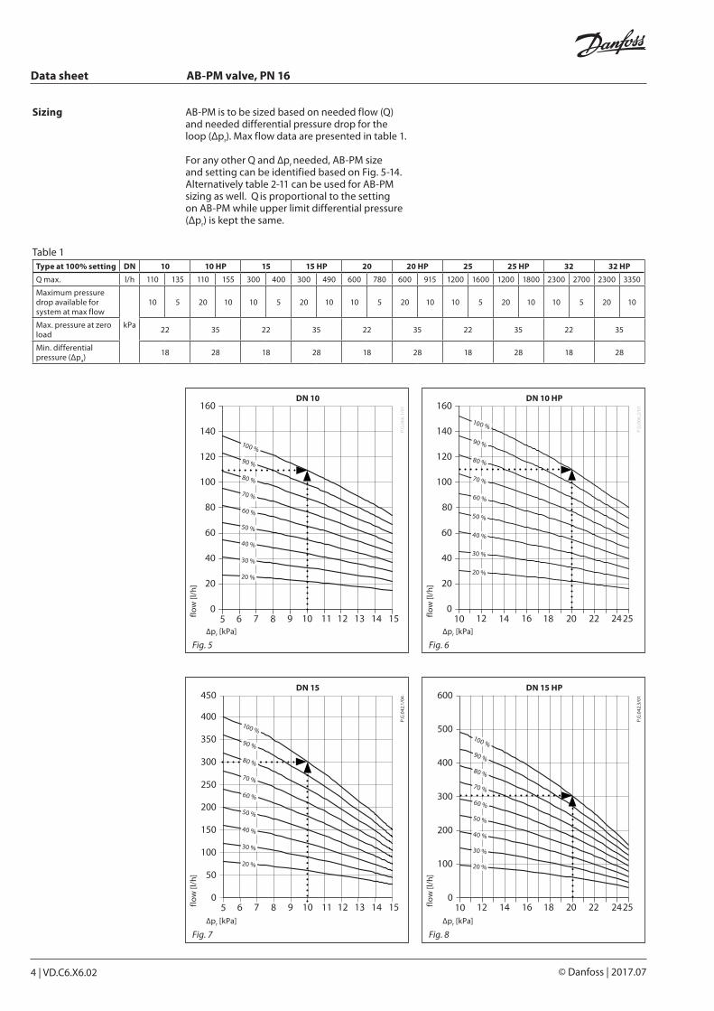
Sizing AB-PM is to be sized based on needed flow (Q) and needed differential pressure drop for the loop (Δpr). Max flow data are presented in table 1.
For any other Q and ∆pr needed, AB-PM size and setting can be identified based on Fig. 5-14. Alternatively table 2-11 can be used for AB-PM sizing as well. Q is proportional to the setting on AB-PM while upper limit differential pressure (Δpr) is kept the same.
Table 1Type at 100% setting DN 10 10 HP 15 15 HP 20 20 HP 25 25 HP 32 32 HP
Q max. l/h 110 135 110 155 300 400 300 490 600 780 600 915 1200 1600 1200 1800 2300 2700 2300 3350
Maximum pressure drop available for system at max flow
kPa
10 5 20 10 10 5 20 10 10 5 20 10 10 5 20 10 10 5 20 10
Max. pressure at zero load
22 35 22 35 22 35 22 35 22 35
Min. differential pressure (Δpa)
18 28 18 28 18 28 18 28 18 28
Fig. 5 Fig. 6
Fig. 7 Fig. 8

Data sheet AB-PM valve, PN 16
VD.C6.X6.02 | 5© Danfoss | 2017.07
Fig. 13 Fig. 14
DN 20 HP
∆pr [kPa]
flow
[l/h
]
20 %
30 %
40 %
50 %
60 %
90 %
100 %
80 %
70 %
DN 20
∆pr [kPa]
flow
[l/h
]
20 %
30 %
40 %
50 %
60 %
70 %
90 %
100 %
80 %
DN 25 HP
∆pr [kPa]
flow
[l/h
]
20 %
30 %
40 %
50 %
60 %
90 %
100 %
80 %
70 %
DN 25
∆pr [kPa]
flow
[l/h
]
20 %
30 %
40 %
50 %
60 %
70 %
90 %
100 %
80 %
Fig. 11 Fig. 12
DN 32 HP
∆pr [kPa]
flow
[l/h
]
20 %
30 %
40 %
50 %
60 %
90 %
100 %
80 %
70 %
DN 32
∆pr [kPa]
flow
[l/h
]
20 %
30 %
40 %
50 %
60 %
70 %
100 %
80 %
90 %
Fig. 9 Fig. 10
Sizing (continuous)
Data sheet AB-PM valve, PN 16
6 | VD.C6.X6.02 © Danfoss | 2017.07
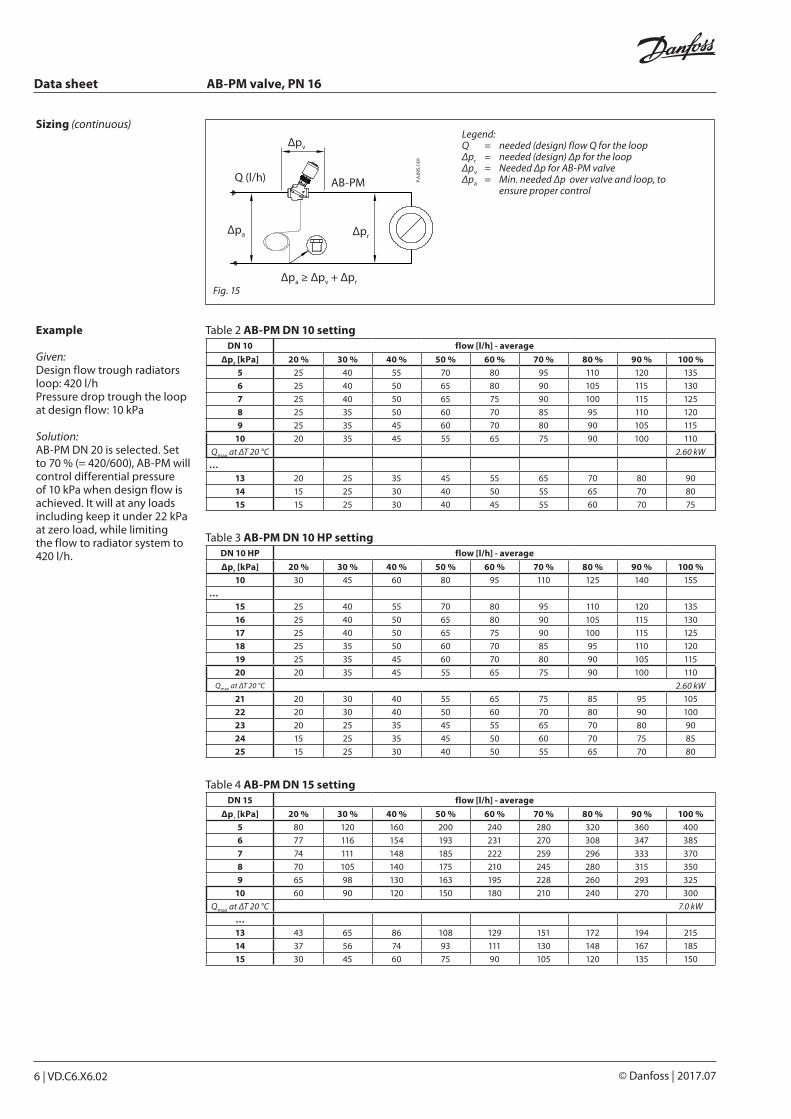
Δpa ≥ Δpv + Δpr
Δpa Δpr
AB-PM
Δpv
Q (l/h)
Example
Given:Design flow trough radiators loop: 420 l/hPressure drop trough the loop at design flow: 10 kPa
Solution:AB-PM DN 20 is selected. Set to 70 % (= 420/600), AB-PM will control differential pressure of 10 kPa when design flow is achieved. It will at any loads including keep it under 22 kPa at zero load, while limiting the flow to radiator system to 420 l/h.
Sizing (continuous)
Table 2 AB-PM DN 10 settingDN 10 flow [l/h] - average
Δpr [kPa] 20 % 30 % 40 % 50 % 60 % 70 % 80 % 90 % 100 %5 25 40 55 70 80 95 110 120 135
6 25 40 50 65 80 90 105 115 130
7 25 40 50 65 75 90 100 115 125
8 25 35 50 60 70 85 95 110 120
9 25 35 45 60 70 80 90 105 115
10 20 35 45 55 65 75 90 100 110
Qmax at ΔT 20 °C 2.60 kW
…13 20 25 35 45 55 65 70 80 90
14 15 25 30 40 50 55 65 70 80
15 15 25 30 40 45 55 60 70 75
Table 3 AB-PM DN 10 HP settingDN 10 HP flow [l/h] - average
Δpr [kPa] 20 % 30 % 40 % 50 % 60 % 70 % 80 % 90 % 100 %10 30 45 60 80 95 110 125 140 155
…15 25 40 55 70 80 95 110 120 135
16 25 40 50 65 80 90 105 115 130
17 25 40 50 65 75 90 100 115 125
18 25 35 50 60 70 85 95 110 120
19 25 35 45 60 70 80 90 105 115
20 20 35 45 55 65 75 90 100 110Qmax at ΔT 20 °C 2.60 kW
21 20 30 40 55 65 75 85 95 105
22 20 30 40 50 60 70 80 90 100
23 20 25 35 45 55 65 70 80 90
24 15 25 35 45 50 60 70 75 85
25 15 25 30 40 50 55 65 70 80
Table 4 AB-PM DN 15 settingDN 15 flow [l/h] - average
Δpr [kPa] 20 % 30 % 40 % 50 % 60 % 70 % 80 % 90 % 100 %5 80 120 160 200 240 280 320 360 400
6 77 116 154 193 231 270 308 347 385
7 74 111 148 185 222 259 296 333 370
8 70 105 140 175 210 245 280 315 350
9 65 98 130 163 195 228 260 293 325
10 60 90 120 150 180 210 240 270 300
Qmax at ΔT 20 °C 7.0 kW
…13 43 65 86 108 129 151 172 194 215
14 37 56 74 93 111 130 148 167 185
15 30 45 60 75 90 105 120 135 150
Legend:Q = needed (design) flow Q for the loopΔpr = needed (design) Δp for the loopΔpv = Needed Δp for AB-PM valveΔpa = Min. needed Δp over valve and loop, to ensure proper control
Fig. 15

Data sheet AB-PM valve, PN 16
VD.C6.X6.02 | 7© Danfoss | 2017.07
Table 5 AB-PM DN 15 HP settingDN 15 HP flow [l/h] - average
Δpr [kPa] 20 % 30 % 40 % 50 % 60 % 70 % 80 % 90 % 100 %10 100 145 195 245 295 345 390 440 490
…15 85 125 165 210 250 290 330 375 415
16 80 120 160 200 235 275 315 355 395
17 75 115 150 190 225 265 300 340 375
18 70 105 140 175 210 245 280 315 350
19 65 100 130 165 195 225 260 295 325
20 60 90 120 150 180 210 240 270 300
Qmax at ΔT 20 °C 7.0 kW
21 55 85 110 140 165 195 220 250 275
22 50 75 100 125 150 175 200 225 250
23 45 65 90 110 130 155 175 200 220
24 40 55 75 95 115 135 150 170 190
25 30 50 65 80 95 110 130 145 160
Table 6 AB-PM DN 20 settingDN 20 flow [l/h] - average
∆pr [kPa] 20 % 30 % 40 % 50 % 60 % 70 % 80 % 90 % 100 %5 155 235 310 390 470 545 625 700 780
6 150 225 300 375 450 525 600 675 750
7 140 215 285 355 425 495 570 640 710
8 135 205 270 340 410 475 545 610 680
9 130 190 255 320 385 450 510 575 640
10 120 180 240 300 360 420 480 540 600
Qmax at ΔT 20 °C 13.9 kW
…13 85 130 170 215 260 300 345 385 430
14 75 110 150 185 220 260 295 335 370
15 60 90 120 150 180 210 240 270 300
Table 7 AB-PM DN 20 HP settingDN 20 HP flow [l/h] - average
Δpr [kPa] 20 % 30 % 40 % 50 % 60 % 70 % 80 % 90 % 100 %10 185 275 370 460 550 645 735 830 920
…15 160 235 315 395 475 555 630 710 790
16 150 225 300 380 455 530 605 680 755
17 145 215 290 360 430 505 575 650 720
18 135 205 270 340 410 475 545 610 680
19 130 190 255 320 385 450 510 575 640
20 120 180 240 300 360 420 480 540 600
Qmax at ΔT 20 °C 13.9 kW
21 110 165 220 275 325 380 435 490 545
22 100 150 200 250 295 345 395 445 495
23 90 130 175 220 265 310 350 395 440
24 75 115 155 195 230 270 310 345 385
25 65 100 130 165 195 225 260 295 325
Table 8 AB-PM DN 25 settingDN 25 flow [l/h] - average
∆pr [kPa] 20 % 30 % 40 % 50 % 60 % 70 % 80 % 90 % 100 %5 310 470 625 780 935 1090 1250 1405 1560
6 300 450 600 750 900 1050 1200 1350 1500
7 285 425 570 710 850 995 1135 1280 1420
8 270 410 545 680 815 950 1090 1225 1360
9 255 385 510 640 770 895 1025 1150 1280
10 240 360 480 600 720 840 960 1080 1200
Qmax at ΔT 20 °C 27.9 kW
…13 170 260 345 430 515 600 690 775 860
14 150 220 295 370 445 520 590 665 740
15 120 180 240 300 360 420 480 540 600
Sizing (continuous)
Data sheet AB-PM valve, PN 16
8 | VD.C6.X6.02 © Danfoss | 2017.07
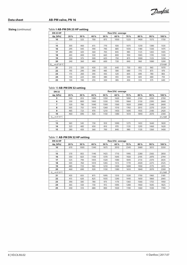
Table 9 AB-PM DN 25 HP settingDN 25 HP flow [l/h] - average
Δpr [kPa] 20 % 30 % 40 % 50 % 60 % 70 % 80 % 90 % 100 %10 350 525 700 875 1050 1225 1400 1575 1750
…15 305 460 615 770 920 1075 1230 1380 1535
16 295 445 590 740 885 1035 1180 1330 1475
17 280 420 560 705 845 985 1125 1265 1405
18 265 400 530 665 800 930 1065 1195 1330
19 250 375 500 625 750 875 1000 1125 1250
20 240 360 480 600 720 840 960 1080 1200
Qmax at ΔT 20 °C 27.9 kW
21 215 320 430 535 640 750 855 965 1070
22 195 290 390 485 580 680 775 875 970
23 175 260 345 435 520 605 690 780 865
24 150 225 300 380 455 530 605 680 755
25 130 190 255 320 385 450 510 575 640
Table 10 AB-PM DN 32 settingDN 32 flow [l/h] - average
∆pr [kPa] 20 % 30 % 40 % 50 % 60 % 70 % 80 % 90 % 100 %5 540 810 1080 1350 1620 1890 2160 2430 2700
6 530 800 1065 1330 1595 1860 2130 2395 2660
7 520 780 1040 1300 1560 1820 2080 2340 2600
8 505 755 1010 1260 1510 1765 2015 2270 2520
9 485 725 970 1210 1450 1695 1935 2180 2420
10 460 690 920 1150 1380 1610 1840 2070 2300Qmax at ΔT 20 °C 51.2 kW
…13 365 545 730 910 1090 1275 1455 1640 1820
14 325 485 650 810 970 1135 1295 1460 1620
15 280 420 560 700 840 980 1120 1260 1400
Table 11 AB-PM DN 32 HP settingDN 32 HP flow [l/h] - average
Δpr [kPa] 20 % 30 % 40 % 50 % 60 % 70 % 80 % 90 % 100 %10 670 1005 1340 1675 2010 2345 2680 3015 3350
…15 570 855 1140 1425 1710 1995 2280 2565 2850
16 550 825 1100 1370 1645 1920 2195 2470 2744
17 525 790 1055 1320 1580 1845 2110 2370 2635
18 505 760 1010 1265 1515 1770 2020 2275 2525
19 485 725 965 1210 1450 1690 1930 2175 2415
20 460 690 920 1150 1380 1610 1840 2070 2300Qmax at ΔT 20 °C 51.2 kW
21 435 655 875 1095 1310 1530 1750 1965 2185
22 415 620 825 1035 1240 1445 1650 1860 2065
23 390 585 780 975 1170 1365 1560 1755 1950
24 365 550 730 915 1095 1280 1460 1645 1825
25 340 510 680 850 1020 1190 1360 1530 1700
Sizing (continuous)

Data sheet AB-PM valve, PN 16
VD.C6.X6.02 | 9© Danfoss | 2017.07
9
Design
1. Spindle 2. Stuffing box 3. Pointer 4. Control valve’s cone 5. Membrane 6. Main spring 7. Hollow cone (pressure
controller) 8. Vulcanized seat (pressure
controller) 9. Impulse tube
Fig. 16) AB-PM, DN 10-32
AB-PM is a combined automatic balancing valve. It is working as Δp controller, flow limiter and zone controller. Higher pressure acts on the upper side of the control diaphragm (5) while via an impulse tube (9) lower pressure in the return pipe acts on the lower side of the diaphragm. When available pressure increases at partial loads, the membrane closes and thus keeps stable Δp inside the controlled loop. Δp controller keeps constant differential pressure on the controlled loop including the control part of AB-PM (similar as if ASV-I would be integrated into ASV-P).
The control part of AB-PM is working as a flow limiter. This enables to set both the design flow as well as needed Δp. The flow rate is defined by presetting AB-PM, based on pressure demand of the loop.
With actuator mounted on the valve, AB-PM can be used as zone valve. When connected to the room controller with time programs, functions such as night setback, holiday mode, etc become available.
Data sheet AB-PM valve, PN 16
10 | VD.C6.X6.02 © Danfoss | 2017.07
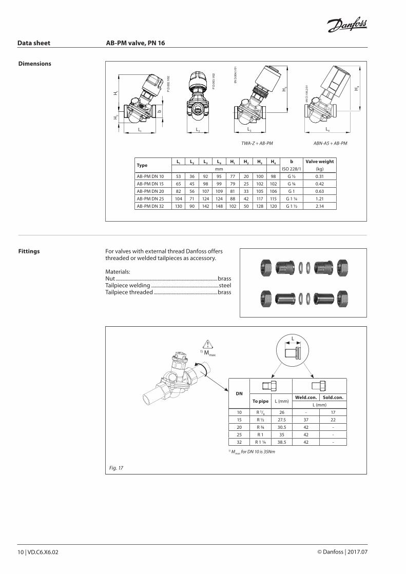
DN
To pipe L (mm)Weld.con. Sold.con.
L (mm)
10 R 3/8 26 - 17
15 R ½ 27.5 37 22
20 R ¾ 30.5 42 -
25 R 1 35 42 -
32 R 1 ¼ 38.5 42 -
1) Mmax for DN 10 is 35Nm
L
H2
H1
b
L1 L2
TWA-Z + AB-PM
H4
ABN-A5 + AB-PM
H3
L3 L4
Dimensions
TypeL1 L2 L3 L4 H1 H2 H3 H4 b Valve weight
mm ISO 228/1 (kg)
AB-PM DN 10 53 36 92 95 77 20 100 98 G ½ 0.31
AB-PM DN 15 65 45 98 99 79 25 102 102 G ¾ 0.42
AB-PM DN 20 82 56 107 109 81 33 105 106 G 1 0.63
AB-PM DN 25 104 71 124 124 88 42 117 115 G 1 ¼ 1.21
AB-PM DN 32 130 90 142 148 102 50 128 120 G 1 ½ 2.14
Fittings For valves with external thread Danfoss offers threaded or welded tailpieces as accessory.
Materials:Nut ................................................................................brassTailpiece welding .....................................................steelTailpiece threaded ..................................................brass
1) Mmax
Fig. 17

Data sheet AB-PM valve, PN 16
VD.C6.X6.02 | 11© Danfoss | 2017.07
Vertical set DN 15
135
107
43 64
11.55
35
65
167.
3
235.
2278.
2
Threaded joint with impulse tube connection
AG 1” flat sealing
AG 1” flat sealing
Elbow connector
1” × 1”
Reduction nipple ¾” × 1”
Red handle¾” × ¾”
Blue handle
¾” × ¾”
Pipe nipple ¾” × 110 mm
Threaded joint ¾” × ¾”
¾” × 1”
Blue handle
AB
-PM
DN
15
¾”
Adapter for impulse tube
AG 1” flat sealing
AG 1” flat sealing
266.2
251.2
65
127
Reduction nipple ¾” × 1”
3/4” × 3/4”
Pipe nipple ¾” × 110 mm
Threaded joint ¾” × ¾”
Blue handle Blue handle
Red handle ¾” × 1”
3/4” × 3/4”
Horizontal set DN 15
Dimensions (continuous)
Fig. 18

Data sheet AB-PM valve, PN 16
12 | VD.C6.X6.02 © Danfoss | 2017.07
Vertical set DN 20
135
107
43 64
11.55
35
82
178.
1
235.
2278.
2
Threaded joint with impulse tube connection
AG 1” flat sealing
AG 1” flat sealing
Elbow connector 1” × 1”
Red handle
¾” × 1”
Blue handle¾” × ¾”
Pipe nipple ¾” × 110 mm
Threaded joint ¾” × ¾”
¾” × 1”
Blue handle
Adapter for impulse tube
AG 1” flat sealing
266.2
251.2
82
146
¾” × ¾”
Pipe nipple ¾” × 110 mm
Threaded joint ¾” × ¾
Blue handle Blue handle
Red handle
¾” × 1”
¾” × 1”
Dimensions (continuous)
Horizontal set DN 20
Fig. 19
Data sheet AB-PM valve, PN 16
VD.C6.X6.02 | 13© Danfoss | 2017.07
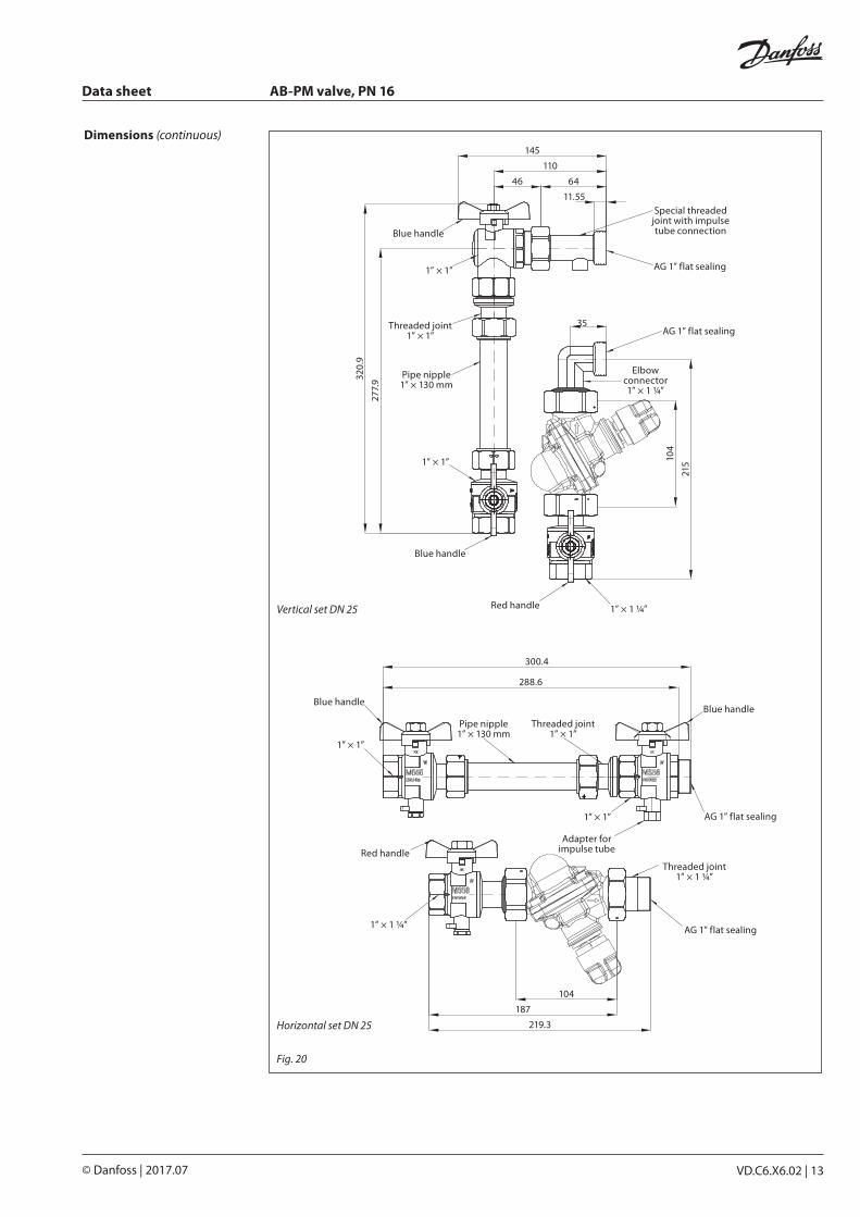
Vertical set DN 25
145
110
46 64
11.55
35
104
215
277.
9320.
9
Special threaded joint with impulse tube connection
AG 1” flat sealing
AG 1” flat sealing
Elbow connector 1” × 1 ¼”
Red handle 1” × 1 ¼”
Blue handle
1” × 1”
Pipe nipple 1” × 130 mm
Threaded joint 1” × 1”
1” × 1”
Blue handle
AG 1” flat sealing
AG 1” flat sealing
300.4
187
219.3
Threaded joint 1” × 1 ¼”
1” × 1”
Pipe nipple 1” × 130 mm
Threaded joint 1” × 1”
Blue handleBlue handle
Red handle
1” × 1”
1” × 1 ¼”
104
Adapter for impulse tube
288.6
Horizontal set DN 25
Dimensions (continuous)
Fig. 20
Data sheet AB-PM valve, PN 16
14 | VD.C6.X6.02 © Danfoss | 2017.07
Tender text AB-PM - Combined Automatic Balancing ValveBranch should be balanced with a differential pressure controller for dynamic hydronic balance, with following characteristics:
• Valve should keep differential pressure across the branch by membrane driven controller.• Valve should have shut-off function. • Valve should have possibility to mount actuator. • Valve should have variable setting. Setting value should allow to set a combination of
needed ∆p and max flow limitation.• Setting should be lockable to prevent unauthorized change.• Valve should have metal to metal sealing to ensure sufficient performance of differential
pressure control at low flows.• Shut-off service function should be possible to do by hand / without a tool.• Valve should be delivered with impulse tube. Diameter of impulse tube should not be
bigger than 1.2 mm.• Valve should be delivered in reliable packaging for safe transport and handling.
Product characteristics:
a. Pressure class: PN 16b. Temperature range: −10 … +120 °C.c. Connection size: DN10-DN32d. Connection type: External thread ISO 228/1e. Valve body material: DZR brass f. Installation: on flow pipe with connection via impulse tube to return pipe.g. DN10-32: Δp setting range: 5-15 kPa Nom. flow at 10 kPa: 110 l/h (DN10), 300 l/h (DN15), 600 l/h (DN20), 1200 l/h (DN25)
and 2300 l/h (DN32) Minimum Δp across valve and loop 18 kPa to ensure proper control Max Δp at zero flow: 22 kPa Max Δp across the valve: 4 barh. DN10-32 HP: Δp setting range: 10-25 kPa Nom flow at 20 kPa: 110 l/h (DN10), 300 l/h (DN15), 600 l/h (DN20), 1200 l/h (DN25) and 2300
l/h (DN32) Minimum Δp across valve and loop 28 kPa to ensure proper control Max Δp at zero flow: 35 kPa Max Δp across the valve: 4 bar

Data sheet AB-PM valve, PN 16
VD.C6.X6.02 | 15© Danfoss | 2017.07

© Danfoss | DHS-SRMT/SI | 2017.0716 | VD.C6.X6.02
Danfoss can accept no responsibility for possible errors in catalogues, brochures and other printed material. Danfoss reserves the right to alter its products without notice. This also applies to products already on order provided that such alterations can be made without subsequential changes being necessary eady agreed.All trademarks in this material are property of the respective companies. Danfoss and the Danfoss logotype are trademarks of Danfoss A/S. All rights reserved.
Data sheet AB-PM valve, PN 16
Top Related