


Languages
Pages
Legal

INSTALLATION | OPERATION | MAINTENANCE
1
1920 E Broadway Road Tempe, AZ 85282 T: 480.968.9550 F: 480.968.9555 E: [email protected]
www.unitedmetal.com Information subject to change without notice. Custom Air Handlers (IOM Oct. 2020)
a imminently hazardous situa-
CUSTOM AIR HANDLERS
IMPORTANT SAFETY INSTRUCTIONS
READ AND SAVE THIS MANUAL
For future reference, record Tag, Model & Serial numbers of your unit here:
Tag No. ___________ Model No. ____________________ Serial No. ____________________
ABOUT THIS MANUAL
This document is intended for use by owner-authorized
personnel. It is expected that these individuals possess
independent training that will enable them to perform their
assigned task properly and safely. It is essential that, prior
to performing any task on this equipment, these individuals
shall have read and understood this document and any ref-
erenced materials. These individuals shall also be familiar
with and comply with all applicable governmental stand-
ards and regulations pertaining to the task in question.
Custom Air Handling equipment design can be complex and
the internal components diverse. This manual is not intend-
ed to provide installation, operation and maintenance infor-
mation for all components but rather a general knowledge
of the air handler itself. This manual must be used in con-
junction with the individual components IOM's for a more
comprehensive understanding of the unit.
SAFETY SYMBOLS
WARNING: indicates a potentially hazardous situation,
which if not avoided, could result in death or serious
injury
CAUTION: indicates a potentially hazardous situation,
which if not avoided, could result in minor or moderate
injury.
NOTE: is used to highlight additional information that
may be helpful to you or may indicate a situation that
could result in equipment or property damage.
!
***To obtain a printed copy of these instructions please email [email protected]***
INSTALLATION | OPERATION | MAINTENANCE
2
1920 E Broadway Road Tempe, AZ 85282 T: 480.968.9550 F: 480.968.9555 E: [email protected]
www.unitedmetal.com Information subject to change without notice. Custom Air Handlers (IOM Oct. 2020)
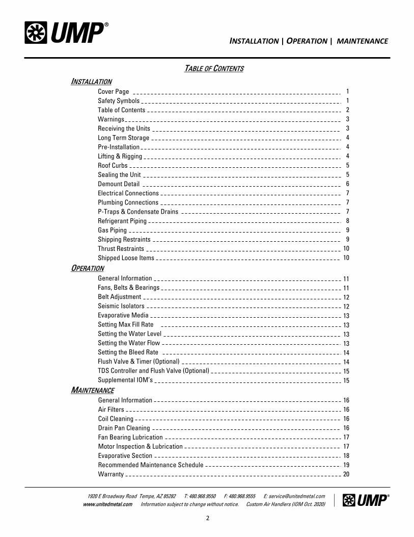
TABLE OF CONTENTS
INSTALLATION
Cover Page
Safety Symbols
Table of Contents
Warnings
Receiving the Units
Long Term Storage
Pre-Installation
Lifting & Rigging
Roof Curbs
Sealing the Unit
Demount Detail
Electrical Connections
Plumbing Connections
P-Traps & Condensate Drains
Refrigerant Piping
Gas Piping
Shipping Restraints
Thrust Restraints
Shipped Loose Items
OPERATION
General Information
Fans, Belts & Bearings
Belt Adjustment
Seismic Isolators
Evaporative Media
Setting Max Fill Rate
Setting the Water Level
Setting the Water Flow
Setting the Bleed Rate
Flush Valve & Timer (Optional)
TDS Controller and Flush Valve (Optional)
Supplemental IOM’s
MAINTENANCE
General Information
Air Filters
Coil Cleaning
Drain Pan Cleaning
Fan Bearing Lubrication
Motor Inspection & Lubrication
Evaporative Section
Recommended Maintenance Schedule
Warranty
1
1
2
3
3
4
4
4
5
5
6
7
7
7
8
9
9
10
10
11
11
12
12
13
13
13
13
14
14
15
15
16
16
16
16
17
17
18
19
20
INSTALLATION | OPERATION | MAINTENANCE
3
1920 E Broadway Road Tempe, AZ 85282 T: 480.968.9550 F: 480.968.9555 E: [email protected]
www.unitedmetal.com Information subject to change without notice. Custom Air Handlers (IOM Oct. 2020)
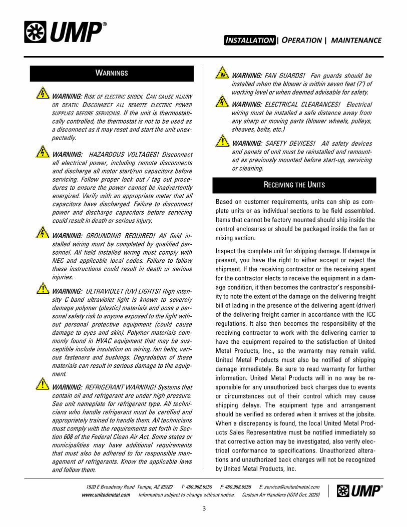
WARNINGS
RECEIVING THE UNITS
Based on customer requirements, units can ship as com-
plete units or as individual sections to be field assembled.
Items that cannot be factory mounted should ship inside the
control enclosures or should be packaged inside the fan or
mixing section.
Inspect the complete unit for shipping damage. If damage is
present, you have the right to either accept or reject the
shipment. If the receiving contractor or the receiving agent
for the contractor elects to receive the equipment in a dam-
age condition, it then becomes the contractor’s responsibil-
ity to note the extent of the damage on the delivering freight
bill of lading in the presence of the delivering agent (driver)
of the delivering freight carrier in accordance with the ICC
regulations. It also then becomes the responsibility of the
receiving contractor to work with the delivering carrier to
have the equipment repaired to the satisfaction of United
Metal Products, Inc., so the warranty may remain valid.
United Metal Products must also be notified of shipping
damage immediately. Be sure to read warranty for further
information. United Metal Products will in no way be re-
sponsible for any unauthorized back charges due to events
or circumstances out of their control which may cause
shipping delays. The equipment type and arrangement
should be verified as ordered when it arrives at the jobsite.
When a discrepancy is found, the local United Metal Prod-
ucts Sales Representative must be notified immediately so
that corrective action may be investigated, also verify elec-
trical conformance to specifications. Unauthorized altera-
tions and unauthorized back charges will not be recognized
by United Metal Products, Inc.
WARNING: RISK OF ELECTRIC SHOCK. CAN CAUSE INJURY
OR DEATH: DISCONNECT ALL REMOTE ELECTRIC POWER
SUPPLIES BEFORE SERVICING. If the unit is thermostati-
cally controlled, the thermostat is not to be used as
a disconnect as it may reset and start the unit unex-
pectedly.
WARNING: HAZARDOUS VOLTAGES! Disconnect
all electrical power, including remote disconnects
and discharge all motor start/run capacitors before
servicing. Follow proper lock out / tag out proce-
dures to ensure the power cannot be inadvertently
energized. Verify with an appropriate meter that all
capacitors have discharged. Failure to disconnect
power and discharge capacitors before servicing
could result in death or serious injury.
WARNING: GROUNDING REQUIRED! All field in-
stalled wiring must be completed by qualified per-
sonnel. All field installed wiring must comply with
NEC and applicable local codes. Failure to follow
these instructions could result in death or serious
injuries.
WARNING: ULTRAVIOLET (UV) LIGHTS! High inten-
sity C-band ultraviolet light is known to severely
damage polymer (plastic) materials and pose a per-
sonal safety risk to anyone exposed to the light with-
out personal protective equipment (could cause
damage to eyes and skin). Polymer materials com-
monly found in HVAC equipment that may be sus-
ceptible include insulation on wiring, fan belts, vari-
ous fasteners and bushings. Degradation of these
materials can result in serious damage to the equip-
ment.
!
WARNING: REFRIGERANT WARNING! Systems that
contain oil and refrigerant are under high pressure.
See unit nameplate for refrigerant type. All techni-
cians who handle refrigerant must be certified and
appropriately trained to handle them. All technicians
must comply with the requirements set forth in Sec-
tion 608 of the Federal Clean Air Act. Some states or
municipalities may have additional requirements
that must also be adhered to for responsible man-
agement of refrigerants. Know the applicable laws
and follow them.
!
WARNING: FAN GUARDS! Fan guards should be
installed when the blower is within seven feet (7’) of
working level or when deemed advisable for safety.
WARNING: ELECTRICAL CLEARANCES! Electrical
wiring must be installed a safe distance away from
any sharp or moving parts (blower wheels, pulleys,
sheaves, belts, etc.)
WARNING: SAFETY DEVICES! All safety devices
and panels of unit must be reinstalled and remount-
ed as previously mounted before start-up, servicing
or cleaning.
!
INSTALLATION
INSTALLATION | OPERATION | MAINTENANCE
4
1920 E Broadway Road Tempe, AZ 85282 T: 480.968.9550 F: 480.968.9555 E: [email protected]
www.unitedmetal.com Information subject to change without notice. Custom Air Handlers (IOM Oct. 2020)
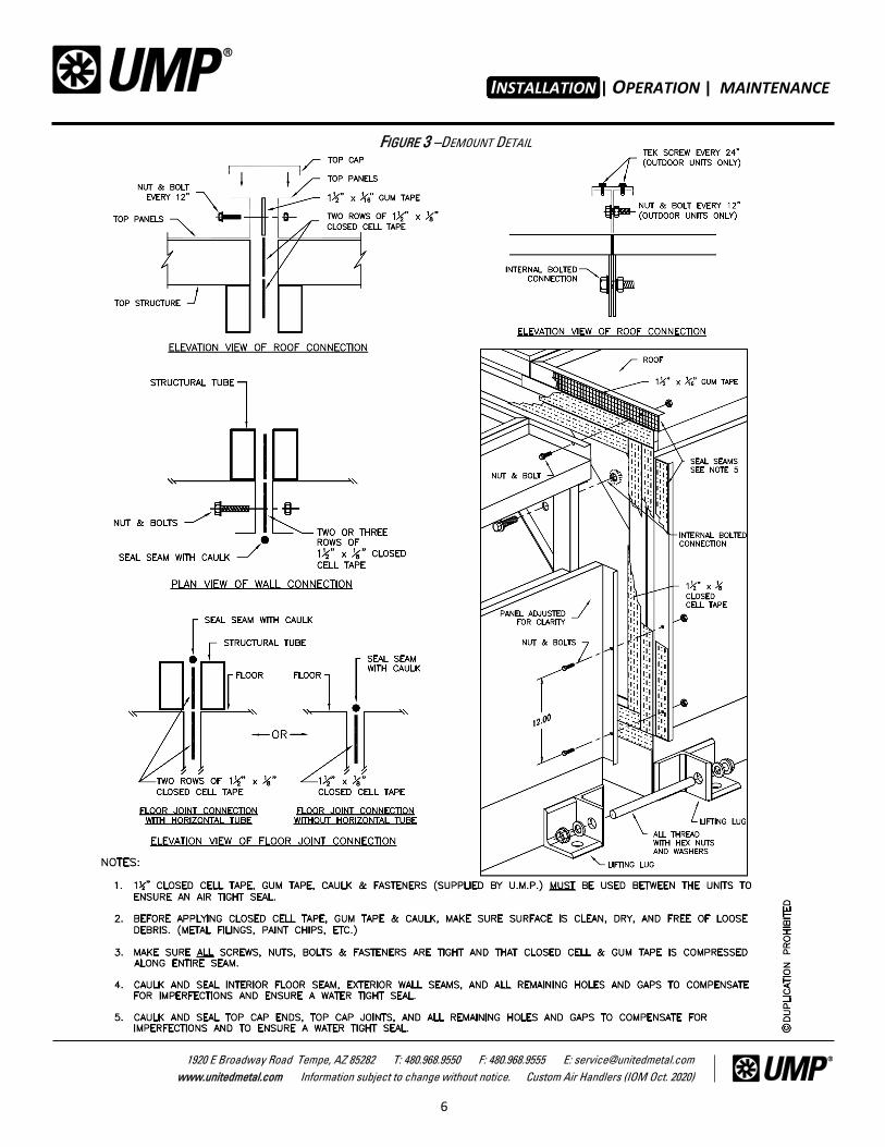
provided in this manual (Fig. 3) or shipped loose with
the gasket material. Gasket material will be supplied in
a box, shipped loose with the unit. There is a time limit of one year from startup or 18 months
from date of shipment , whichever is sooner, that any unit
may be kept in long-term storage. At the end of this period,
the unit must be in operation. During the storage period, any
component containing bearings must be rotated every 30
days.
Select a well drained area, preferably concrete or a black-
top surface. Place the unit on a dry surface or raised off the
ground to ensure adequate air circulation beneath the unit
and to ensure no portion of the unit will contact standing
water at any time. Unit must be stored on a flat and level
surface. Any plastic shipping material provided with the unit
for shipping protection must be removed within 24hrs. Use
Canvas tarps to weather protect equipment prior to installa-
tion.
1. Verify jobsite electrical power & phase match units
nameplate.
2. Verify electrical and plumbing connections are oriented
correctly to jobsite plan’s, spec’s, schedule and ap-
proved submittal.
3. Verify mounting surface is dimensionally correct,
square, flat and level.
4. Prepare unit for lifting & rigging. Remove any shipping
material that might interfere with the joining of de-
mounted sections.
5. If the unit has demounted sections, prepare mating
surfaces prior to rigging. Follow demount instructions
LONG TERM STORAGE
PRE-INSTALLATION
LIFTING & RIGGING
NOTE: WARRANTY: The warranty does not cover
damage to the unit or controls due to negligence
during storage.
NOTE: USE ONLY CANVAS TARPS TO COVER AIR
HANDLERS. Plastic tarps can cause condensation
to form in and on the equipment, which could result
in corrosion, wet storage stains or other damage.
NOTE: Failure to perform the long-term storage re-
quirements past 30 days from shipment and properly
log these required procedures will void the warran-
ty.
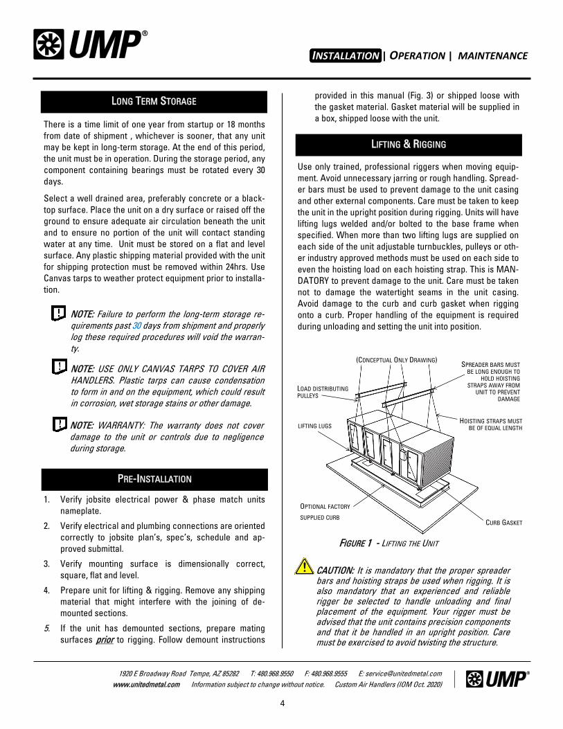
CAUTION: It is mandatory that the proper spreader bars and hoisting straps be used when rigging. It is also mandatory that an experienced and reliable rigger be selected to handle unloading and final placement of the equipment. Your rigger must be advised that the unit contains precision components and that it be handled in an upright position. Care must be exercised to avoid twisting the structure.
!
FIGURE 1 - LIFTING THE UNIT
LIFTING LUGS HOISTING STRAPS MUST
BE OF EQUAL LENGTH
(CONCEPTUAL ONLY DRAWING)
LOAD DISTRIBUTING PULLEYS
SPREADER BARS MUST BE LONG ENOUGH TO
HOLD HOISTING STRAPS AWAY FROM
UNIT TO PREVENT DAMAGE
OPTIONAL FACTORY
SUPPLIED CURB CURB GASKET
INSTALLATION
Use only trained, professional riggers when moving equip-
ment. Avoid unnecessary jarring or rough handling. Spread-
er bars must be used to prevent damage to the unit casing
and other external components. Care must be taken to keep
the unit in the upright position during rigging. Units will have
lifting lugs welded and/or bolted to the base frame when
specified. When more than two lifting lugs are supplied on
each side of the unit adjustable turnbuckles, pulleys or oth-
er industry approved methods must be used on each side to
even the hoisting load on each hoisting strap. This is MAN-
DATORY to prevent damage to the unit. Care must be taken
not to damage the watertight seams in the unit casing.
Avoid damage to the curb and curb gasket when rigging
onto a curb. Proper handling of the equipment is required
during unloading and setting the unit into position.
INSTALLATION | OPERATION | MAINTENANCE
5
1920 E Broadway Road Tempe, AZ 85282 T: 480.968.9550 F: 480.968.9555 E: [email protected]
www.unitedmetal.com Information subject to change without notice. Custom Air Handlers (IOM Oct. 2020)
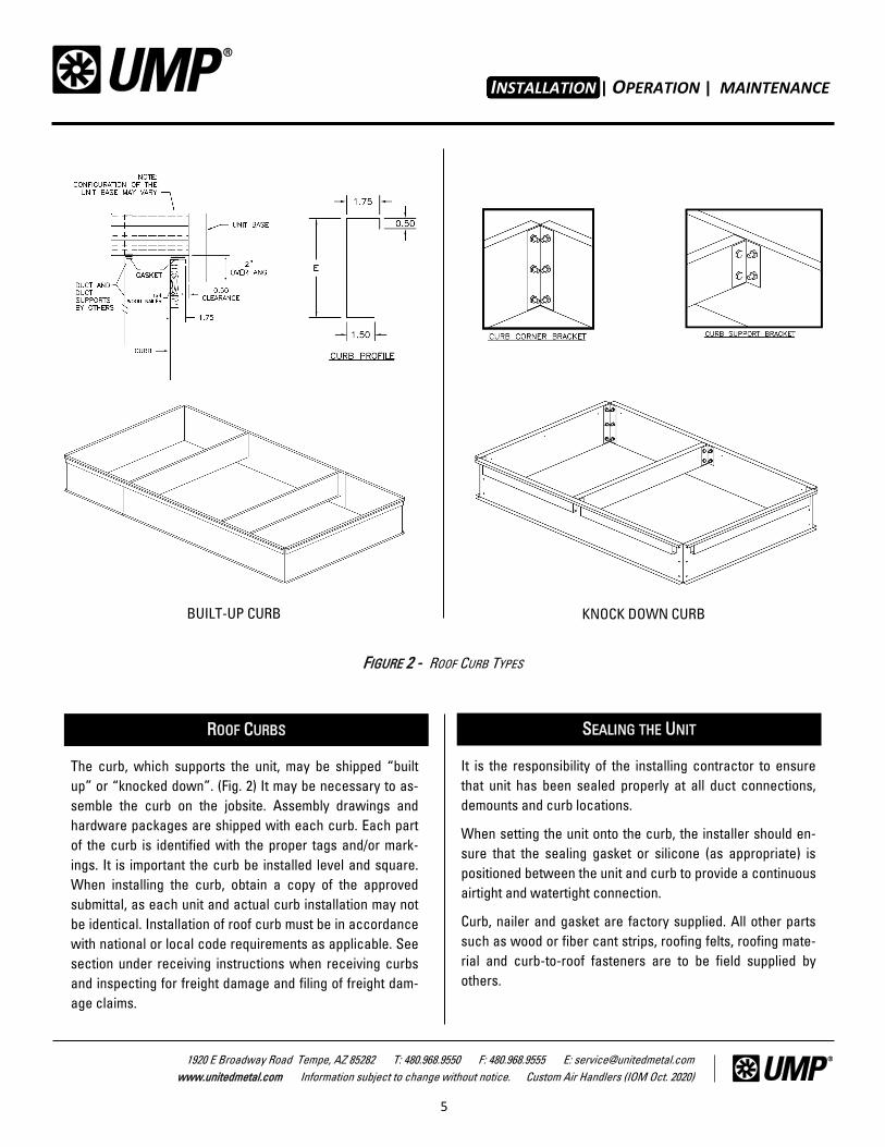
The curb, which supports the unit, may be shipped “built
up” or “knocked down”. (Fig. 2) It may be necessary to as-
semble the curb on the jobsite. Assembly drawings and
hardware packages are shipped with each curb. Each part
of the curb is identified with the proper tags and/or mark-
ings. It is important the curb be installed level and square.
When installing the curb, obtain a copy of the approved
submittal, as each unit and actual curb installation may not
be identical. Installation of roof curb must be in accordance
with national or local code requirements as applicable. See
section under receiving instructions when receiving curbs
and inspecting for freight damage and filing of freight dam-
age claims.
ROOF CURBS
It is the responsibility of the installing contractor to ensure
that unit has been sealed properly at all duct connections,
demounts and curb locations.
When setting the unit onto the curb, the installer should en-
sure that the sealing gasket or silicone (as appropriate) is
positioned between the unit and curb to provide a continuous
airtight and watertight connection.
Curb, nailer and gasket are factory supplied. All other parts
such as wood or fiber cant strips, roofing felts, roofing mate-
rial and curb-to-roof fasteners are to be field supplied by
others.
SEALING THE UNIT
INSTALLATION
FIGURE 2 - ROOF CURB TYPES
BUILT-UP CURB KNOCK DOWN CURB
INSTALLATION | OPERATION | MAINTENANCE
6
1920 E Broadway Road Tempe, AZ 85282 T: 480.968.9550 F: 480.968.9555 E: [email protected]
www.unitedmetal.com Information subject to change without notice. Custom Air Handlers (IOM Oct. 2020)
FIGURE 3 –DEMOUNT DETAIL
INSTALLATION
INSTALLATION | OPERATION | MAINTENANCE
7
1920 E Broadway Road Tempe, AZ 85282 T: 480.968.9550 F: 480.968.9555 E: [email protected]
www.unitedmetal.com Information subject to change without notice. Custom Air Handlers (IOM Oct. 2020)
Support all piping independently of the coils. Provide swing
joints or flexible fittings on all connections that are adjacent
to heating coils to absorb thermal expansion and contrac-
tion strains. Use a backup wrench when attaching piping to
coils to prevent damage to the coil header. Properly seal all
penetrations in unit casing. Failure to seal penetrations from
inner panel to outer panel may result in unconditioned air
entering the unit, and water infiltrating the insulation, result-
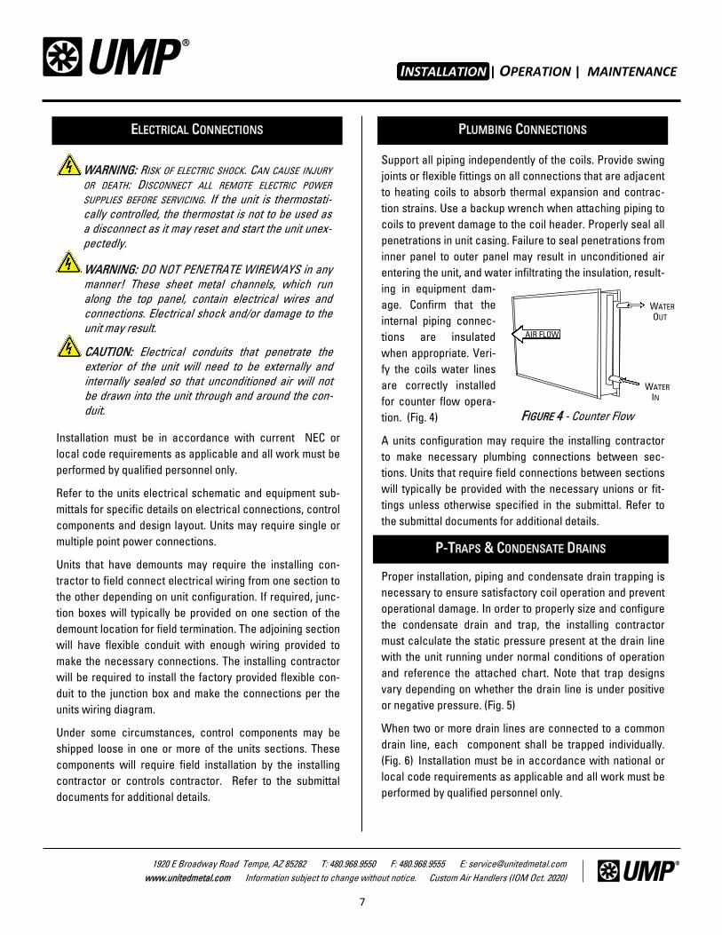
ing in equipment dam-
age. Confirm that the
internal piping connec-
tions are insulated
when appropriate. Veri-
fy the coils water lines
are correctly installed
for counter flow opera-
tion. (Fig. 4)
A units configuration may require the installing contractor
to make necessary plumbing connections between sec-
tions. Units that require field connections between sections
will typically be provided with the necessary unions or fit-
tings unless otherwise specified in the submittal. Refer to
the submittal documents for additional details.
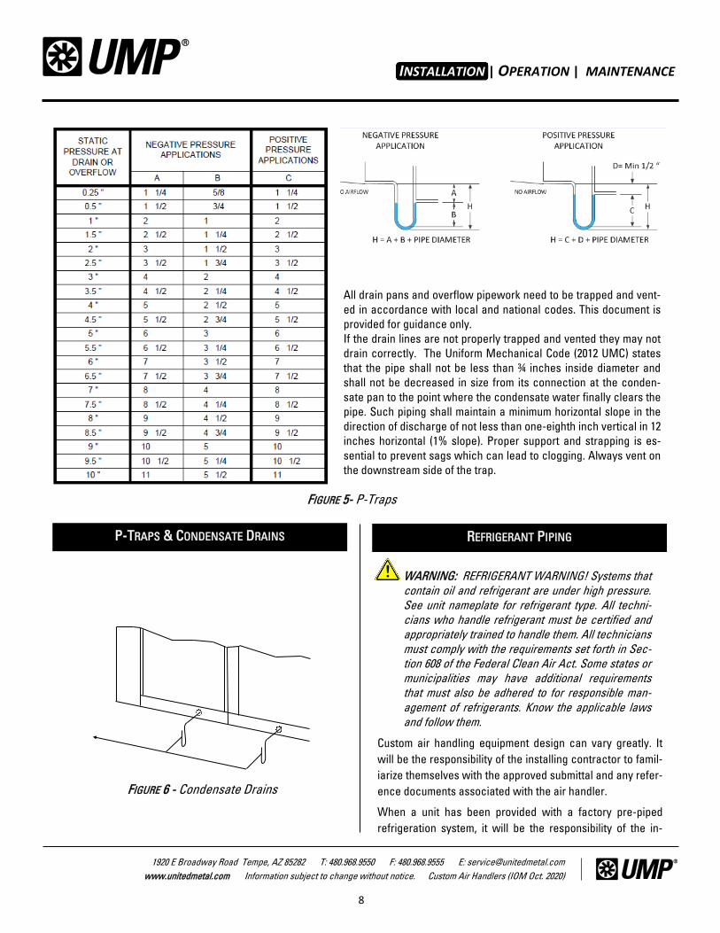
Proper installation, piping and condensate drain trapping is
necessary to ensure satisfactory coil operation and prevent
operational damage. In order to properly size and configure
the condensate drain and trap, the installing contractor
must calculate the static pressure present at the drain line
with the unit running under normal conditions of operation
and reference the attached chart. Note that trap designs
vary depending on whether the drain line is under positive
or negative pressure. (Fig. 5)
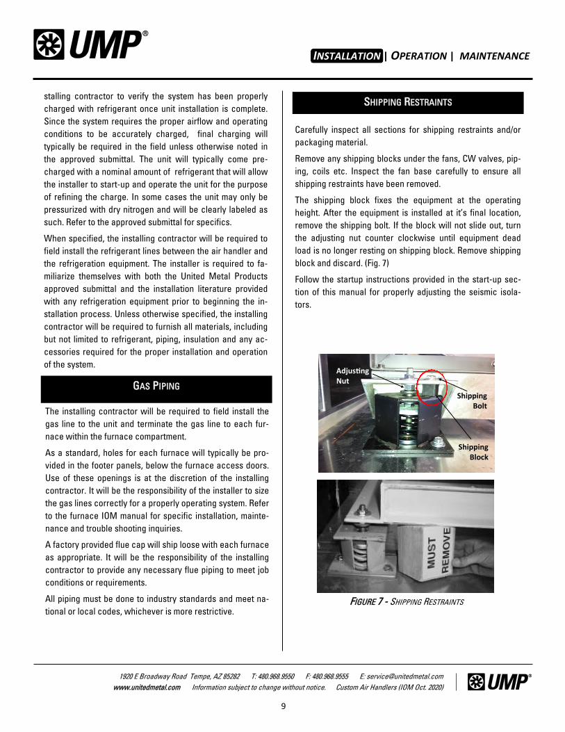
When two or more drain lines are connected to a common
drain line, each component shall be trapped individually.
(Fig. 6) Installation must be in accordance with national or
local code requirements as applicable and all work must be
performed by qualified personnel only.
Installation must be in accordance with current NEC or
local code requirements as applicable and all work must be
performed by qualified personnel only.
Refer to the units electrical schematic and equipment sub-
mittals for specific details on electrical connections, control
components and design layout. Units may require single or
multiple point power connections.
Units that have demounts may require the installing con-
tractor to field connect electrical wiring from one section to
the other depending on unit configuration. If required, junc-
tion boxes will typically be provided on one section of the
demount location for field termination. The adjoining section
will have flexible conduit with enough wiring provided to
make the necessary connections. The installing contractor
will be required to install the factory provided flexible con-
duit to the junction box and make the connections per the
units wiring diagram.
Under some circumstances, control components may be
shipped loose in one or more of the units sections. These
components will require field installation by the installing
contractor or controls contractor. Refer to the submittal
documents for additional details.
ELECTRICAL CONNECTIONS PLUMBING CONNECTIONS
INSTALLATION
FIGURE 4 - Counter Flow
AIR FLOW
WATER OUT
WATER IN
WARNING: RISK OF ELECTRIC SHOCK. CAN CAUSE INJURY
OR DEATH: DISCONNECT ALL REMOTE ELECTRIC POWER
SUPPLIES BEFORE SERVICING. If the unit is thermostati-
cally controlled, the thermostat is not to be used as
a disconnect as it may reset and start the unit unex-
pectedly.
WARNING: DO NOT PENETRATE WIREWAYS in any
manner! These sheet metal channels, which run
along the top panel, contain electrical wires and
connections. Electrical shock and/or damage to the
unit may result.
CAUTION: Electrical conduits that penetrate the
exterior of the unit will need to be externally and
internally sealed so that unconditioned air will not
be drawn into the unit through and around the con-
duit.
P-TRAPS & CONDENSATE DRAINS
INSTALLATION | OPERATION | MAINTENANCE
8
1920 E Broadway Road Tempe, AZ 85282 T: 480.968.9550 F: 480.968.9555 E: [email protected]
www.unitedmetal.com Information subject to change without notice. Custom Air Handlers (IOM Oct. 2020)
All drain pans and overflow pipework need to be trapped and vent-
ed in accordance with local and national codes. This document is
provided for guidance only.
If the drain lines are not properly trapped and vented they may not
drain correctly. The Uniform Mechanical Code (2012 UMC) states
that the pipe shall not be less than ¾ inches inside diameter and
shall not be decreased in size from its connection at the conden-
sate pan to the point where the condensate water finally clears the
pipe. Such piping shall maintain a minimum horizontal slope in the
direction of discharge of not less than one-eighth inch vertical in 12
inches horizontal (1% slope). Proper support and strapping is es-
sential to prevent sags which can lead to clogging. Always vent on
the downstream side of the trap.
FIGURE 5- P-Traps
Custom air handling equipment design can vary greatly. It
will be the responsibility of the installing contractor to famil-
iarize themselves with the approved submittal and any refer-
ence documents associated with the air handler.
When a unit has been provided with a factory pre-piped
refrigeration system, it will be the responsibility of the in-
P-TRAPS & CONDENSATE DRAINS REFRIGERANT PIPING
WARNING: REFRIGERANT WARNING! Systems that
contain oil and refrigerant are under high pressure.
See unit nameplate for refrigerant type. All techni-
cians who handle refrigerant must be certified and
appropriately trained to handle them. All technicians
must comply with the requirements set forth in Sec-
tion 608 of the Federal Clean Air Act. Some states or
municipalities may have additional requirements
that must also be adhered to for responsible man-
agement of refrigerants. Know the applicable laws
and follow them.
!
INSTALLATION
FIGURE 6 - Condensate Drains
INSTALLATION | OPERATION | MAINTENANCE
9
1920 E Broadway Road Tempe, AZ 85282 T: 480.968.9550 F: 480.968.9555 E: [email protected]
www.unitedmetal.com Information subject to change without notice. Custom Air Handlers (IOM Oct. 2020)
GAS PIPING
stalling contractor to verify the system has been properly
charged with refrigerant once unit installation is complete.
Since the system requires the proper airflow and operating
conditions to be accurately charged, final charging will
typically be required in the field unless otherwise noted in
the approved submittal. The unit will typically come pre-
charged with a nominal amount of refrigerant that will allow
the installer to start-up and operate the unit for the purpose
of refining the charge. In some cases the unit may only be
pressurized with dry nitrogen and will be clearly labeled as
such. Refer to the approved submittal for specifics.
When specified, the installing contractor will be required to
field install the refrigerant lines between the air handler and
the refrigeration equipment. The installer is required to fa-
miliarize themselves with both the United Metal Products
approved submittal and the installation literature provided
with any refrigeration equipment prior to beginning the in-
stallation process. Unless otherwise specified, the installing
contractor will be required to furnish all materials, including
but not limited to refrigerant, piping, insulation and any ac-
cessories required for the proper installation and operation
of the system.
The installing contractor will be required to field install the
gas line to the unit and terminate the gas line to each fur-
nace within the furnace compartment.
As a standard, holes for each furnace will typically be pro-
vided in the footer panels, below the furnace access doors.
Use of these openings is at the discretion of the installing
contractor. It will be the responsibility of the installer to size
the gas lines correctly for a properly operating system. Refer
to the furnace IOM manual for specific installation, mainte-
nance and trouble shooting inquiries.
A factory provided flue cap will ship loose with each furnace
as appropriate. It will be the responsibility of the installing
contractor to provide any necessary flue piping to meet job
conditions or requirements.
All piping must be done to industry standards and meet na-
tional or local codes, whichever is more restrictive.
Adjusting Nut
Shipping Bolt
Shipping Block
FIGURE 7 - SHIPPING RESTRAINTS
SHIPPING RESTRAINTS
INSTALLATION
Carefully inspect all sections for shipping restraints and/or
packaging material.
Remove any shipping blocks under the fans, CW valves, pip-
ing, coils etc. Inspect the fan base carefully to ensure all
shipping restraints have been removed.
The shipping block fixes the equipment at the operating
height. After the equipment is installed at it’s final location,
remove the shipping bolt. If the block will not slide out, turn
the adjusting nut counter clockwise until equipment dead
load is no longer resting on shipping block. Remove shipping
block and discard. (Fig. 7)
Follow the startup instructions provided in the start-up sec-
tion of this manual for properly adjusting the seismic isola-
tors.
INSTALLATION | OPERATION | MAINTENANCE
10
1920 E Broadway Road Tempe, AZ 85282 T: 480.968.9550 F: 480.968.9555 E: [email protected]
www.unitedmetal.com Information subject to change without notice. Custom Air Handlers (IOM Oct. 2020)
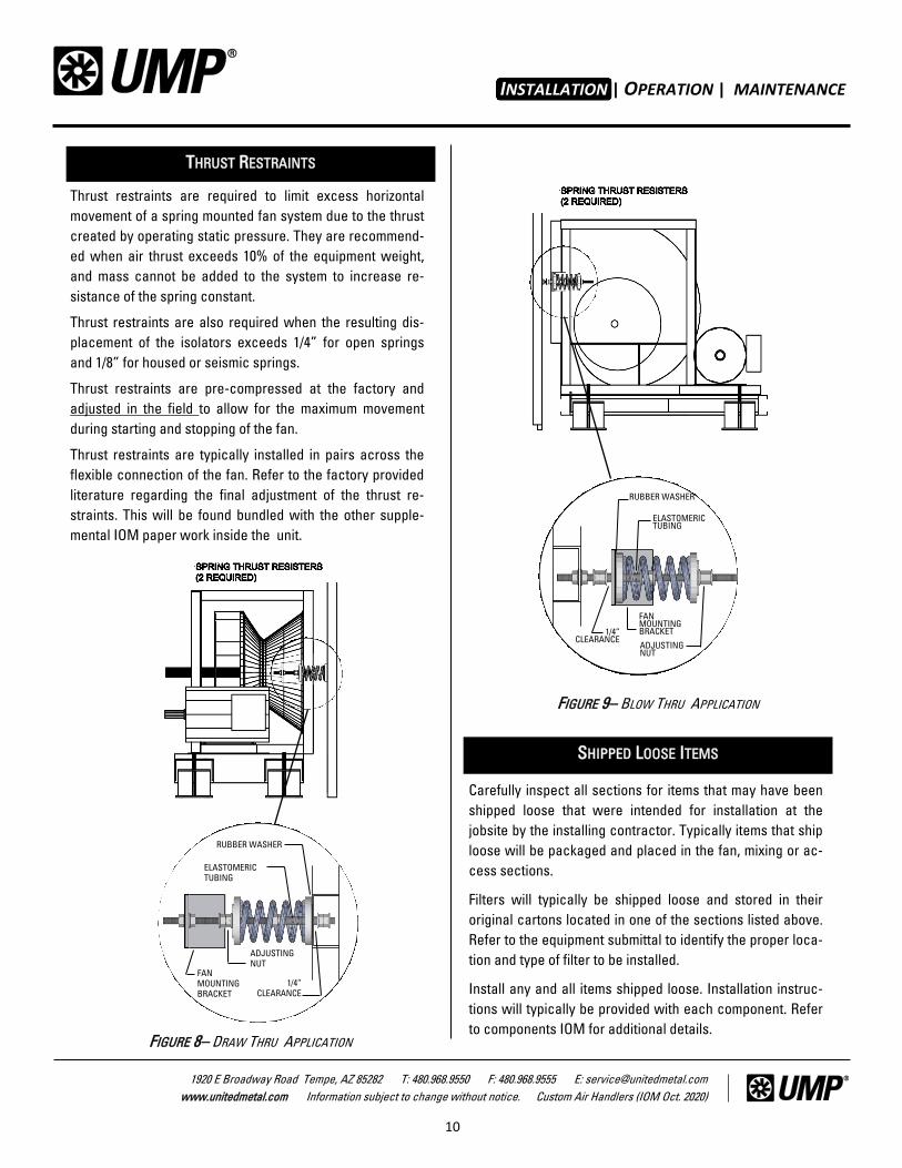
Thrust restraints are required to limit excess horizontal
movement of a spring mounted fan system due to the thrust
created by operating static pressure. They are recommend-
ed when air thrust exceeds 10% of the equipment weight,
and mass cannot be added to the system to increase re-
sistance of the spring constant.
Thrust restraints are also required when the resulting dis-
placement of the isolators exceeds 1/4” for open springs
and 1/8” for housed or seismic springs.
Thrust restraints are pre-compressed at the factory and
adjusted in the field to allow for the maximum movement
during starting and stopping of the fan.
Thrust restraints are typically installed in pairs across the
flexible connection of the fan. Refer to the factory provided
literature regarding the final adjustment of the thrust re-
straints. This will be found bundled with the other supple-
mental IOM paper work inside the unit.
THRUST RESTRAINTS
INSTALLATION
Carefully inspect all sections for items that may have been
shipped loose that were intended for installation at the
jobsite by the installing contractor. Typically items that ship
loose will be packaged and placed in the fan, mixing or ac-
cess sections.
Filters will typically be shipped loose and stored in their
original cartons located in one of the sections listed above.
Refer to the equipment submittal to identify the proper loca-
tion and type of filter to be installed.
Install any and all items shipped loose. Installation instruc-
tions will typically be provided with each component. Refer
to components IOM for additional details.
SHIPPED LOOSE ITEMS
FIGURE 8– DRAW THRU APPLICATION
ELASTOMERIC
TUBING
ADJUSTING
NUT
1/4”
CLEARANCE
FAN
MOUNTING
BRACKET
RUBBER WASHER
FIGURE 9– BLOW THRU APPLICATION
ELASTOMERIC TUBING
ADJUSTING NUT
1/4” CLEARANCE
FAN MOUNTING BRACKET
RUBBER WASHER
INSTALLATION | OPERATION | MAINTENANCE
11
1920 E Broadway Road Tempe, AZ 85282 T: 480.968.9550 F: 480.968.9555 E: [email protected]
www.unitedmetal.com Information subject to change without notice. Custom Air Handlers (IOM Oct. 2020)
GENERAL INFORMATION
NOTE: IMPORTANT! Email, mail or fax the Startup
form to United Metal Products within 30 days of
startup for warranty validation.
OPERATION
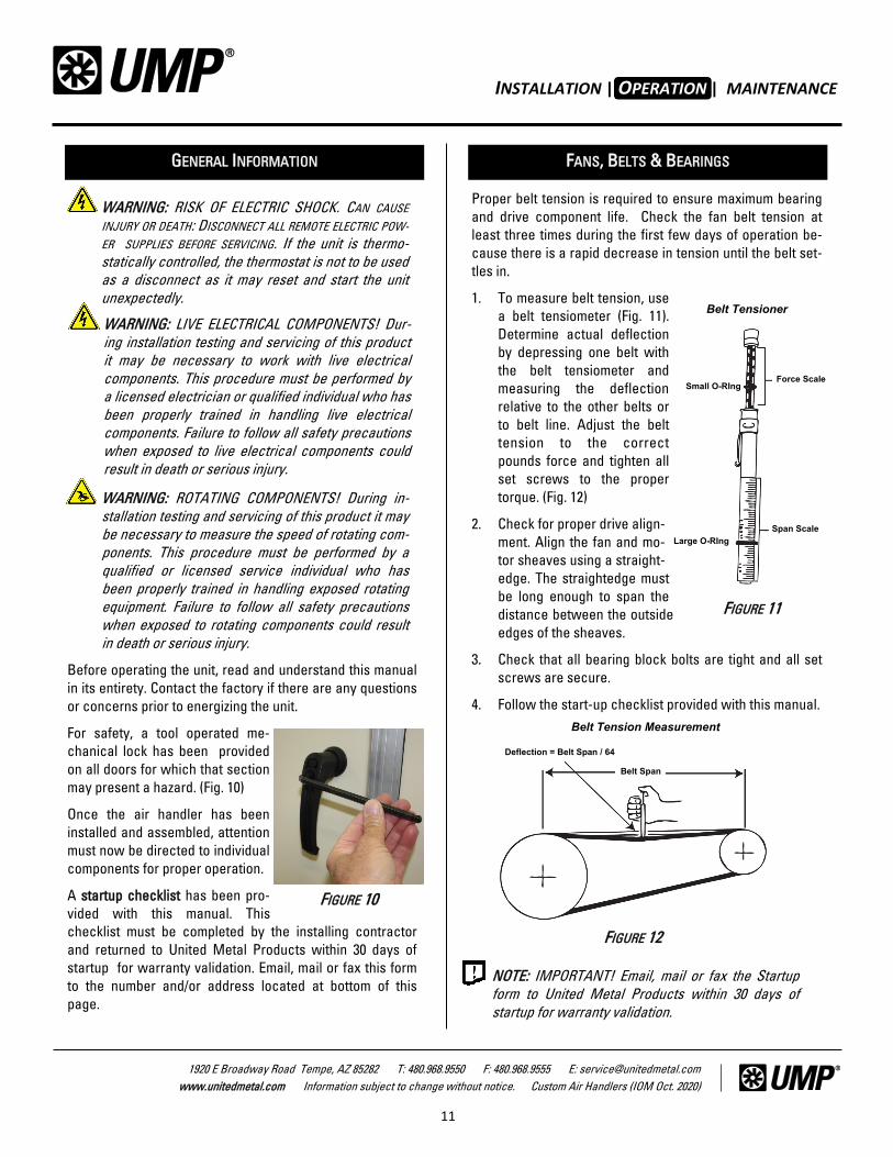
Proper belt tension is required to ensure maximum bearing
and drive component life. Check the fan belt tension at
least three times during the first few days of operation be-
cause there is a rapid decrease in tension until the belt set-
tles in.
1. To measure belt tension, use
a belt tensiometer (Fig. 11).
Determine actual deflection
by depressing one belt with
the belt tensiometer and
measuring the deflection
relative to the other belts or
to belt line. Adjust the belt
tension to the correct
pounds force and tighten all
set screws to the proper
torque. (Fig. 12)
2. Check for proper drive align-
ment. Align the fan and mo-
tor sheaves using a straight-
edge. The straightedge must
be long enough to span the
distance between the outside
edges of the sheaves.
3. Check that all bearing block bolts are tight and all set
screws are secure.
4. Follow the start-up checklist provided with this manual.
Before operating the unit, read and understand this manual
in its entirety. Contact the factory if there are any questions
or concerns prior to energizing the unit.
For safety, a tool operated me-
chanical lock has been provided
on all doors for which that section
may present a hazard. (Fig. 10)
Once the air handler has been
installed and assembled, attention
must now be directed to individual
components for proper operation.
A startup checklist has been pro-
vided with this manual. This
checklist must be completed by the installing contractor
and returned to United Metal Products within 30 days of
startup for warranty validation. Email, mail or fax this form
to the number and/or address located at bottom of this
page.
FANS, BELTS & BEARINGS
WARNING: ROTATING COMPONENTS! During in-
stallation testing and servicing of this product it may
be necessary to measure the speed of rotating com-
ponents. This procedure must be performed by a
qualified or licensed service individual who has
been properly trained in handling exposed rotating
equipment. Failure to follow all safety precautions
when exposed to rotating components could result
in death or serious injury.
WARNING: LIVE ELECTRICAL COMPONENTS! Dur-
ing installation testing and servicing of this product
it may be necessary to work with live electrical
components. This procedure must be performed by
a licensed electrician or qualified individual who has
been properly trained in handling live electrical
components. Failure to follow all safety precautions
when exposed to live electrical components could
result in death or serious injury.
WARNING: RISK OF ELECTRIC SHOCK. CAN CAUSE
INJURY OR DEATH: DISCONNECT ALL REMOTE ELECTRIC POW-
ER SUPPLIES BEFORE SERVICING. If the unit is thermo-
statically controlled, the thermostat is not to be used
as a disconnect as it may reset and start the unit
unexpectedly.
FIGURE 10
FIGURE 12
Belt Tension Measurement
Deflection = Belt Span / 64
Belt Span
Belt Tensioner
Force Scale Small O-RIng
Large O-RIng
Span Scale
FIGURE 11
INSTALLATION | OPERATION | MAINTENANCE
12
1920 E Broadway Road Tempe, AZ 85282 T: 480.968.9550 F: 480.968.9555 E: [email protected]
www.unitedmetal.com Information subject to change without notice. Custom Air Handlers (IOM Oct. 2020)
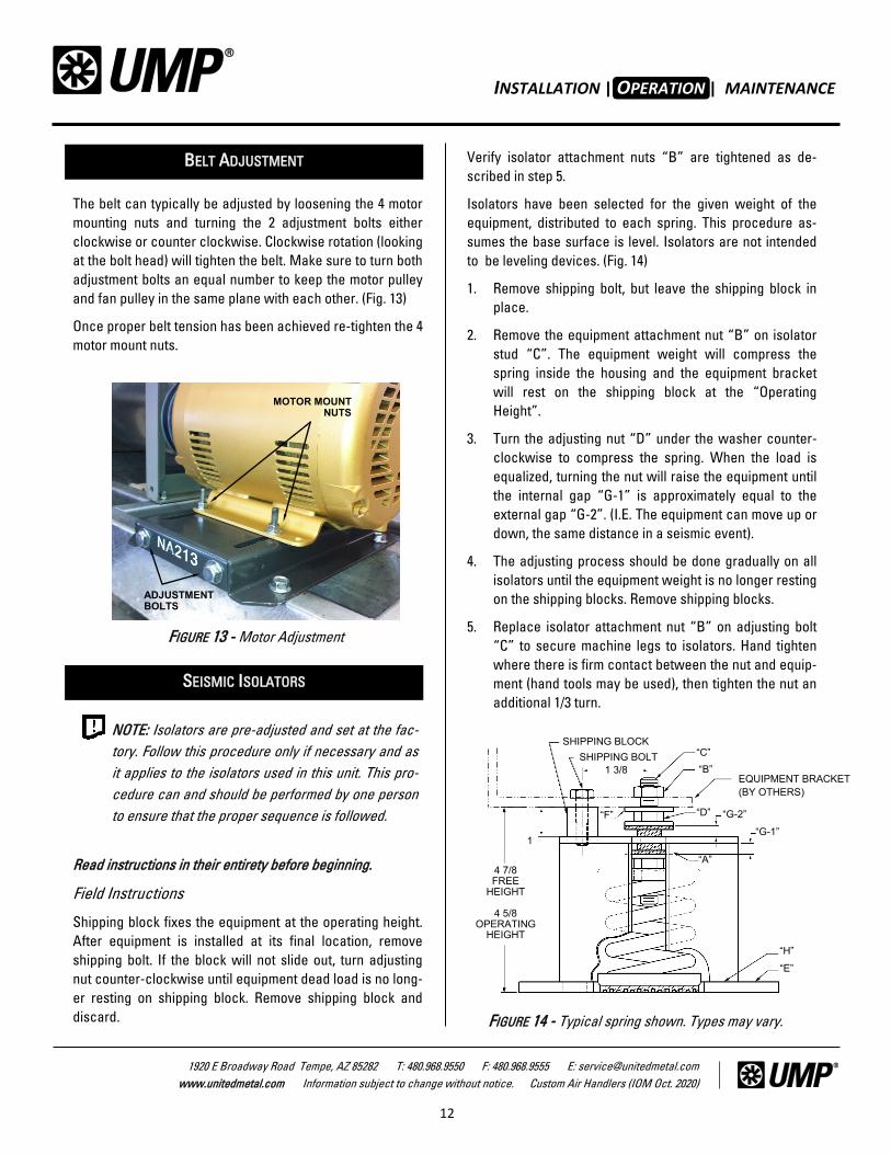
The belt can typically be adjusted by loosening the 4 motor
mounting nuts and turning the 2 adjustment bolts either
clockwise or counter clockwise. Clockwise rotation (looking
at the bolt head) will tighten the belt. Make sure to turn both
adjustment bolts an equal number to keep the motor pulley
and fan pulley in the same plane with each other. (Fig. 13)
Once proper belt tension has been achieved re-tighten the 4
motor mount nuts.
Read instructions in their entirety before beginning.
Field Instructions
Shipping block fixes the equipment at the operating height.
After equipment is installed at its final location, remove
shipping bolt. If the block will not slide out, turn adjusting
nut counter-clockwise until equipment dead load is no long-
er resting on shipping block. Remove shipping block and
discard.
NOTE: Isolators are pre-adjusted and set at the fac-
tory. Follow this procedure only if necessary and as
it applies to the isolators used in this unit. This pro-
cedure can and should be performed by one person
to ensure that the proper sequence is followed.
BELT ADJUSTMENT
SEISMIC ISOLATORS
FIGURE 13 - Motor Adjustment
MOTOR MOUNT NUTS
ADJUSTMENT BOLTS
Verify isolator attachment nuts “B” are tightened as de-
scribed in step 5.
Isolators have been selected for the given weight of the
equipment, distributed to each spring. This procedure as-
sumes the base surface is level. Isolators are not intended
to be leveling devices. (Fig. 14)
1. Remove shipping bolt, but leave the shipping block in
place.
2. Remove the equipment attachment nut “B” on isolator
stud “C”. The equipment weight will compress the
spring inside the housing and the equipment bracket
will rest on the shipping block at the “Operating
Height”.
3. Turn the adjusting nut “D” under the washer counter-
clockwise to compress the spring. When the load is
equalized, turning the nut will raise the equipment until
the internal gap “G-1” is approximately equal to the
external gap “G-2”. (I.E. The equipment can move up or
down, the same distance in a seismic event).
4. The adjusting process should be done gradually on all
isolators until the equipment weight is no longer resting
on the shipping blocks. Remove shipping blocks.
5. Replace isolator attachment nut “B” on adjusting bolt
“C” to secure machine legs to isolators. Hand tighten
where there is firm contact between the nut and equip-
ment (hand tools may be used), then tighten the nut an
additional 1/3 turn.
FIGURE 14 - Typical spring shown. Types may vary.
SHIPPING BLOCK
SHIPPING BOLT
1 3/8
“C”
“B”
“D” “G-2”
“G-1”
“A”
“H”
“E”
4 7/8 FREE
HEIGHT
4 5/8 OPERATING
HEIGHT
EQUIPMENT BRACKET
(BY OTHERS)
“F”
1
OPERATION
INSTALLATION | OPERATION | MAINTENANCE
13
1920 E Broadway Road Tempe, AZ 85282 T: 480.968.9550 F: 480.968.9555 E: [email protected]
www.unitedmetal.com Information subject to change without notice. Custom Air Handlers (IOM Oct. 2020)
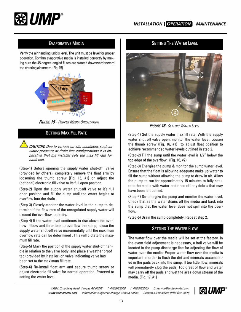
EVAPORATIVE MEDIA
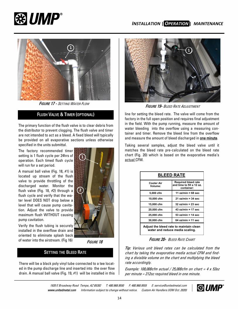
(Step-1) Set the supply water max fill rate. With the supply
water shut off valve open, monitor the water level. Loosen
the thumb screw (Fig. 16, #1) to adjust float position to
achieve recommended water levels outlined in step 2.
(Step-2) Fill the sump until the water level is 1/2” below the
top edge of the overflow. (Fig. 16, #2)
(Step-3) Energize the pump & monitor the sump water level.
Ensure that the float is allowing adequate make up water to
fill the sump without allowing the pump to draw in air. Allow
the pump to run for approximately 15 minutes to fully satu-
rate the media with water and rinse off any debris that may
have been left behind.
(Step-4) De-energize the pump and monitor the water level.
Check that as the water drains off the media and back into
the sump that the water level does not spill into the over-
flow.
(Step-5) Drain the sump completely. Repeat step 2.
The water flow over the media will be set at the factory. In
the event field adjustment is necessary, a ball valve will be
located in the pump discharge line for adjusting the flow of
water over the media. Proper water flow over the media is
important in order to flush the dirt and minerals accumulat-
ed in the pads back into the sump. If too little flow, minerals
will prematurely clog the pads. Too great of flow and water
may carry off the pads and wet the area down stream of the
media. (Fig. 17, #1)
!
1
2
FIGURE 16- SETTING WATER LEVEL
OPERATION
FIGURE 15 - PROPER MEDIA ORIENTATION
Verify the air handling unit is level. The unit must be level for proper
operation. Confirm evaporative media is installed correctly by mak-
ing sure the 45 degree angled flutes are slanted downward toward
the entering air stream. (Fig. 15)
SETTING THE WATER LEVEL
SETTING THE WATER FLOW
SETTING MAX FILL RATE
(Step-1) Before opening the supply water shut-off valve
(provided by others), completely remove the float arm by
loosening the thumb screw (Fig. 16, #1) or adjust the
(optional) electronic fill valve to its full open position.
(Step-2) Open the supply water shut-off valve to it’s full
open position and fill the sump until the water begins to
overflow into the drain.
(Step-3) Closely monitor the water level in the sump to de-
termine if the flow rate of the unregulated supply water will
exceed the overflow capacity.
(Step-4) If the water level continues to rise above the over-
flow elbow and threatens to overflow the sump, close the
supply water shut-off valve incrementally until the maximum
overflow rate can be determined . This will dictate the maxi-
mum fill rate.
(Step-5) Mark the position of the supply water shut-off han-
dle in relation to the valve body and place a weather proof
tag (provided by installer) on valve indicating valve has
been set to the maximum fill rate.
(Step-6) Re-install float arm and secure thumb screw or
adjust electronic fill valve for normal operation. Proceed to
setting the water level.
CAUTION: Due to various on-site conditions such as water pressure or drain line configurations it is im-perative that the installer sets the max fill rate for each unit.
!
INSTALLATION | OPERATION | MAINTENANCE
14
1920 E Broadway Road Tempe, AZ 85282 T: 480.968.9550 F: 480.968.9555 E: [email protected]
www.unitedmetal.com Information subject to change without notice. Custom Air Handlers (IOM Oct. 2020)
There will be a black poly vinyl tube connected to a tee locat-
ed in the pump discharge line and inserted into the over flow
drain. A manual ball valve (Fig. 19, #1) will be installed in this
FIGURE 17 - SETTING WATER FLOW
1
SETTING THE BLEED RATE
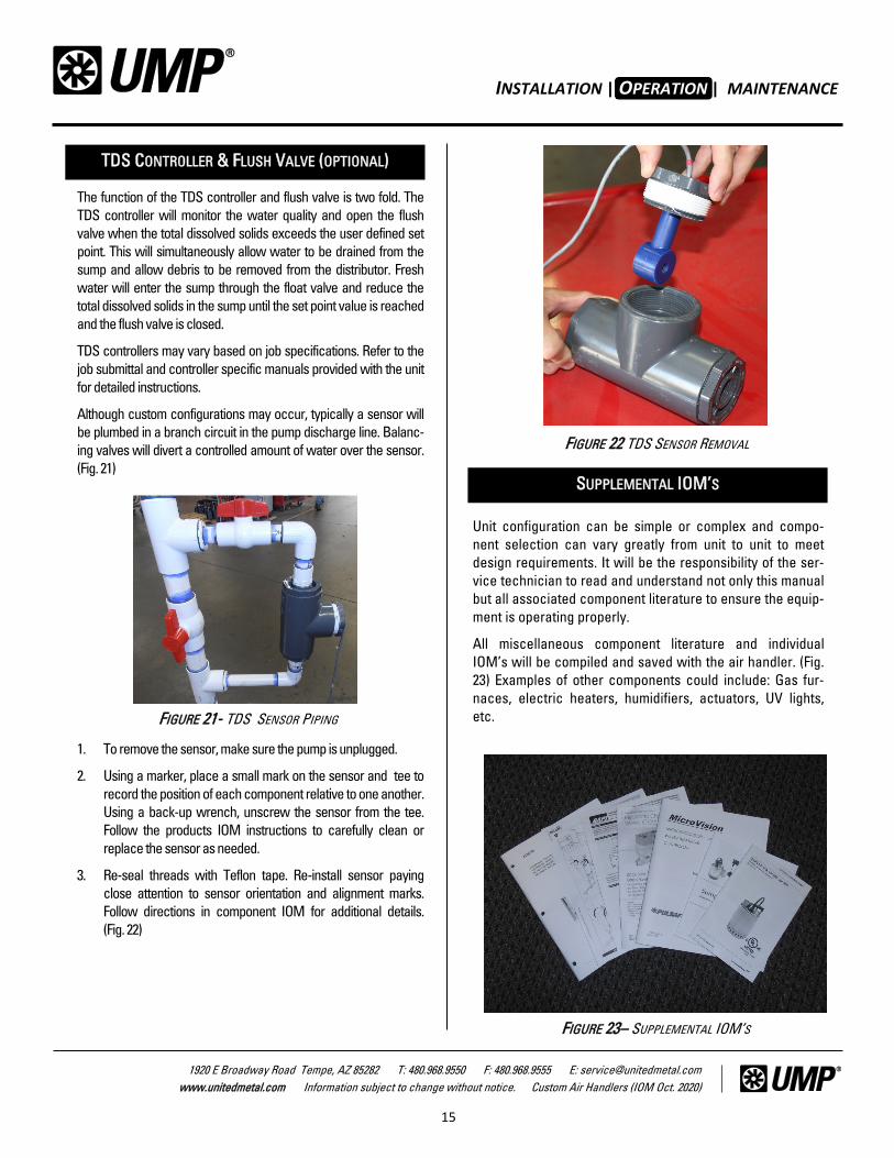
FIGURE 20- BLEED RATE CHART
Adjust the bleed rate to maintain clean water and reduce media scaling.
BLEED RATE
Cooler Air Volume:
Required bleed rate and time to fill a 12 oz.
container:
5,000 cfm
10,000 cfm
15,000 cfm
20,000 cfm
25,000 cfm
30,000 cfm
11 oz/min = 68 sec
21 oz/min = 34 sec
32 oz/min = 23 sec
43 oz/min = 17 sec
53 oz/min = 14 sec
64 oz/min = 11 sec
FIGURE 19- BLEED RATE ADJUSTMENT
1
OPERATION
The primary function of the flush valve is to clear debris from
the distributor to prevent clogging. The flush valve and timer
are not intended to act as a bleed. A fixed bleed will typically
be provided on all evaporative sections unless otherwise
specified in the units submittal.
The factory recommended timer
setting is 1 flush cycle per 24hrs of
operation. Each timed flush cycle
will run for a set period.
A manual ball valve (Fig. 18, #1) is
located up stream of the flush
valve to provide throttling of the
discharged water. Monitor the
flush valve (Fig. 18, #2) through a
flush cycle and verify that the wa-
ter level DOES NOT drop below a
level that will cause pump cavita-
tion. Adjust the valve to provide
maximum flush WITHOUT causing
pump cavitation.
Verify the flush tubing is securely
installed in the overflow drain and
oriented to eliminate splash back
of water into the airstream. (Fig 16)
FLUSH VALVE & TIMER (OPTIONAL)
FIGURE 18
1
2
line for setting the bleed rate. The valve will come from the
factory in the full open position and requires final adjustment
in the field. With the pump running, measure the amount of
water bleeding into the overflow using a measuring con-
tainer and timer. Remove the bleed line from the overflow
and measure the amount of bleed discharged in one minute.
Taking several samples, adjust the bleed valve until it
matches the bleed rate pre-calculated on the bleed rate
chart (Fig. 20) which is based on the evaporative media’s
actual CFM.
Tip: Various unit bleed rates can be calculated from the
chart by taking the evaporative media actual CFM and find-
ing a divisible volume on the chart and multiplying the bleed
rate accordingly.
Example: 100,000cfm actual / 25,000cfm on chart = 4 x 53oz
per minute = 212oz required bleed in one minute.
INSTALLATION | OPERATION | MAINTENANCE
15
1920 E Broadway Road Tempe, AZ 85282 T: 480.968.9550 F: 480.968.9555 E: [email protected]
www.unitedmetal.com Information subject to change without notice. Custom Air Handlers (IOM Oct. 2020)
2
1
6
Unit configuration can be simple or complex and compo-
nent selection can vary greatly from unit to unit to meet
design requirements. It will be the responsibility of the ser-
vice technician to read and understand not only this manual
but all associated component literature to ensure the equip-
ment is operating properly.
All miscellaneous component literature and individual
IOM’s will be compiled and saved with the air handler. (Fig.
23) Examples of other components could include: Gas fur-
naces, electric heaters, humidifiers, actuators, UV lights,
etc.
The function of the TDS controller and flush valve is two fold. The
TDS controller will monitor the water quality and open the flush
valve when the total dissolved solids exceeds the user defined set
point. This will simultaneously allow water to be drained from the
sump and allow debris to be removed from the distributor. Fresh
water will enter the sump through the float valve and reduce the
total dissolved solids in the sump until the set point value is reached
and the flush valve is closed.
TDS controllers may vary based on job specifications. Refer to the
job submittal and controller specific manuals provided with the unit
for detailed instructions.
Although custom configurations may occur, typically a sensor will
be plumbed in a branch circuit in the pump discharge line. Balanc-
ing valves will divert a controlled amount of water over the sensor.
(Fig. 21)
1. To remove the sensor, make sure the pump is unplugged.
2. Using a marker, place a small mark on the sensor and tee to
record the position of each component relative to one another.
Using a back-up wrench, unscrew the sensor from the tee.
Follow the products IOM instructions to carefully clean or
replace the sensor as needed.
3. Re-seal threads with Teflon tape. Re-install sensor paying
close attention to sensor orientation and alignment marks.
Follow directions in component IOM for additional details.
(Fig. 22)
OPERATION
FIGURE 22 TDS SENSOR REMOVAL
TDS CONTROLLER & FLUSH VALVE (OPTIONAL)
SUPPLEMENTAL IOM’S
FIGURE 21- TDS SENSOR PIPING
FIGURE 23– SUPPLEMENTAL IOM’S
INSTALLATION | OPERATION | MAINTENANCE
16
1920 E Broadway Road Tempe, AZ 85282 T: 480.968.9550 F: 480.968.9555 E: [email protected]
www.unitedmetal.com Information subject to change without notice. Custom Air Handlers (IOM Oct. 2020)
INSTALLATION
2
6
MAINTENANCE
Dirt acts as an insulator to heat transfer. Coils will require
periodic cleaning to prevent reduction to performance. Fol-
low the recommended coil cleaning maintenance schedule
outlined in this manual.
Indoor coils typically accumulate dirt and residue that may
require the use of a mild detergent. Numerous products are
available on the market for this purpose. Follow all instruc-
tions and safety procedures provided with the product. Coil
cleaners that are highly acidic are not recommended.
Check that the condensate pan is clean and draining
properly. Verify the condensate trap is clear of debris and
draining adequately. Clean as required.
1. Disconnect all electrical pow er to the unit.
2. Wearing the appropriate personal protective
equipm ent, rem ove any standing w ater.
3. Scrape solid m atter off of the drain pan.
4. Vacuum the drain pan with a vacuum device that
uses high-efficiency particulate arrestance
(HEPA) filters with a m inim um efficiency of 99.97
percent at 0.3 m icron particle size.
5. Thoroughly clean any contam inated area(s) w ith a
m ild bleach and w ater solution or an EPA- ap-
proved sanitizer specifically designed for HVAC
use.
6. Imm ediately rinse the affected surfaces thor-
oughly w ith fresh w ater and a fresh sponge to
prevent potential corrosion of m etal surfaces.
7. Allow the unit to dry com pletely before putting it
back into service.
8. Be careful any contam inated m aterial does not con-
tact other areas of the unit or building.
9. Properly dispose of all contam inated m aterials and
cleaning solution.
Unit configurations can vary greatly. This maintenance
manual provides information intended to inform the service
technician of general maintenance items. Service person-
nel will be required to read and understand any supple-
mental IOM’s provided with individual components and fol-
low the recommended maintenance procedures outlined in
those manuals. Read and comply with all warnings, cau-
tions and notices.
It is important to replace the filters on regular maintenance
cycles. It is also important to replace the filters with the
same filter type that was provided by the factory. Check
that the filters called for are the filters used; failure to use
the filters that the air handler has been designed for can
cause fan motor overload and /or cause the coils to be-
come prematurely dirty and restrict airflow. Refer to the
units data sheet for specific filter type.
FILTER REPLACEMENT:
1. Side Withdraw—Open filter access door, pull filters
along filter slide track (using pull tab) and remove from
unit. Install new filters with the directional arrows
pointing in the direction of airflow.
2. Front Withdraw—Access filter section. Open or re-
move the filter clip. Remove the filter from the rack.
Install new filters with the directional arrows pointing
in the direction of airflow. Secure the filter using the
appropriate clip for each filter.
3. Front Withdraw Slide Track—Access filter section.
Remove filter access cover from filter slide track. Re-
move filters through access section on filter track slid-
ing the filters along the track. Install new filters with
the directional arrows pointing in the direction of air-
flow. Secure the filters by re-installing the filter access
cover on filter track.
GENERAL INFORMATION
WARNING: Disconnect all electric power, including
remote disconnects before servicing. Follow proper
lock-out / tag-out procedures to ensure the power
can not be inadvertently energized.
AIR FILTERS
COIL CLEANING
DRAIN PAN CLEANING
INSTALLATION | OPERATION | MAINTENANCE
17
1920 E Broadway Road Tempe, AZ 85282 T: 480.968.9550 F: 480.968.9555 E: [email protected]
www.unitedmetal.com Information subject to change without notice. Custom Air Handlers (IOM Oct. 2020)
INSTALLATION
2
1
Check that the interior and exterior of the motor is free of
dirt, oil, grease , water, etc. If the motor is not properly venti-
lated, overheating can occur and cause early motor failure.
Use a “Megger” periodically to ensure that the integrity of
the winding insulation has been maintained. Record the
Megger readings. Immediately investigate any significant
drop in insulation resistance.
Check all electrical connections to be sure they are tight.
Bearing grease will lose its lubricating ability over time, not
suddenly. A high grade ball or roller bearing grease should
be used. (Fig. 26)
Be sure that the grease you are adding to the motor is com-
patible with the grease already in the motor. Consult your
motor manufacturer if a grease other than the recommended
type is to be used.
If the motor has a grease outlet plug, make sure the motor is
stopped, clean all grease fittings with a clean cloth.
Below are some general motor lubrication instructions. Fol-
low the specific motor manufacturers instructions for prop-
er lubrication procedures.
1. Remove grease outlet plug.
2. Add the recommended amount of grease.
3. Operate the motor for 15 minutes with the grease plug
removed. This allows excess grease to purge.
4. Reinstall grease outlet plug.
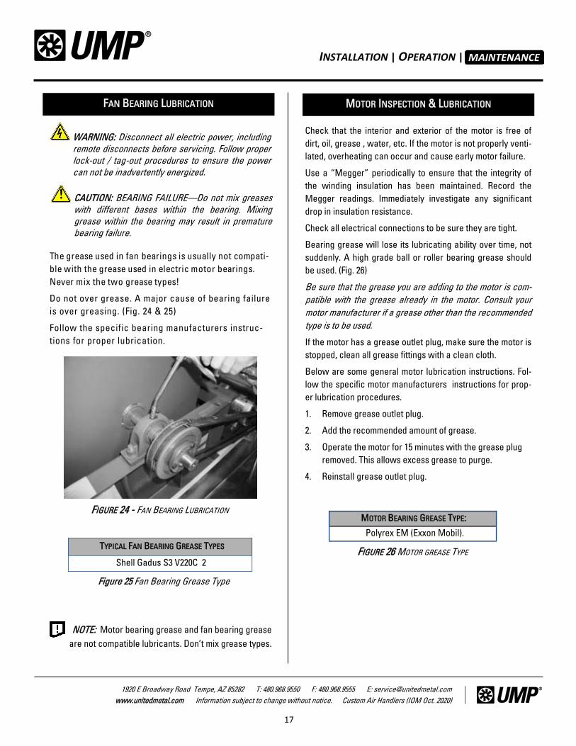
The grease used in fan bearings is usually not compati-
ble w ith the grease used in electric m otor bearings.
Never m ix the tw o grease types!
Do not over grease. A major cause of bearing failure
is over greasing. (Fig. 24 & 25)
Follow the specific bearing manufacturers instruc-
tions for proper lubrication.
MAINTENANCE
FAN BEARING LUBRICATION MOTOR INSPECTION & LUBRICATION
WARNING: Disconnect all electric power, including
remote disconnects before servicing. Follow proper
lock-out / tag-out procedures to ensure the power
can not be inadvertently energized.
CAUTION: BEARING FAILURE—Do not mix greases
with different bases within the bearing. Mixing
grease within the bearing may result in premature
bearing failure.
!
TYPICAL FAN BEARING GREASE TYPES
Shell Gadus S3 V220C 2
FIGURE 25- TYPICAL FAN BEARING GREASE TYPES
FIGURE 24 - FAN BEARING LUBRICATION
NOTE: Motor bearing grease and fan bearing grease
are not compatible lubricants. Don’t mix grease types.
Figure 25 Fan Bearing Grease Type
MOTOR BEARING GREASE TYPE:
Polyrex EM (Exxon Mobil).
FIGURE 26 MOTOR GREASE TYPE

INSTALLATION | OPERATION | MAINTENANCE
18
1920 E Broadway Road Tempe, AZ 85282 T: 480.968.9550 F: 480.968.9555 E: [email protected]
www.unitedmetal.com Information subject to change without notice. Custom Air Handlers (IOM Oct. 2020)
2
Periodic maintenance is critical for the proper operation of
the evaporative section. Follow the recommended mainte-
nance timeline provided at the back of this manual.
Evaporative media should be checked for scale build-up at
the beginning and mid season. Scale build-up can occur
when heavy mineral laden water is not diluted correctly
through the proper use of a bleed. Scale build up can also
be caused from lack of water flow over the media not allow-
ing the minerals to be rinsed back into the sump.
Check that the proper bleed rate is set. (Refer to the opera-
tion section of this manual for instructions on setting the
bleed).
Check & clean the pump inlet screen periodically. Re-
duced water flow will impact cooling performance and
may cause premature media scale build up.
Periodically flush out the distributor manually if an auto-
matic flush kit has not been installed. If an automatic flush
kit has been installed verify it is working properly. (Refer to
the operation section of this manual for flush operation)
(Fig. 18)
The distributor should be periodically cleaned with a dis-
tributor brush to clear any debris blocking the distributor
holes. To access the distributor clean out plug, remove the
media access side panel. Unscrew the distributor end plug,
flush out any debris in distributor, insert the distributor
brush (Fig. 28) and push across the full length of the distrib-
utor (multiple passes may be required to thoroughly clean).
Re-assemble in reverse order. Energize pump and verify
even water distribution on evaporative media face.
At the end of the cooling season it will be necessary to turn
off the water supply to the cooler and drain the reservoir.
Do not leave water standing in unit for prolonged periods
of time while unit is not in use. Make sure the pump has
been unplugged and cannot be energized during shut
down. NEVER operate the water pump without having the
reservoir filled with water.
When replacing the media, be sure the 45 degree angled
flutes are slanted downward toward the entering air
stream (Fig. 15). A removable media frame has been provided
for cleaning dirt & debris that may have collected under the
evaporative media (Fig. 27).
It is not recommended that soft water equipment be at-
tached to any water lines going to the cooler. “Soft Water”
may cause corrosion and decrease effective life of the cool-
er.
FIGURE 27– REMOVEABLE MEDIA FRAME
FIGURE 29– DISTRIBUTOR CLEAN-OUT
MAINTENANCE
EVAPORATIVE SECTION
FIGURE 28 - DISTRIBUTOR CLEANING BRUSH
WARNING: Always disconnect power before servic-
ing pump and evaporative components!
INSTALLATION | OPERATION | MAINTENANCE
19
1920 E Broadway Road Tempe, AZ 85282 T: 480.968.9550 F: 480.968.9555 E: [email protected]
www.unitedmetal.com Information subject to change without notice. Custom Air Handlers (IOM Oct. 2020)
INSTALLATION
2
1
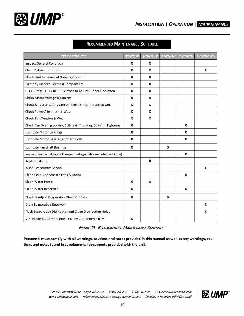
TYPE OF SERVICE STARTUP MONTHLY 3 MONTH 6 MONTH SHUTDOWN
Inspect General Condition X X
Clean Debris from Unit X X X
Check Unit for Unusual Noise & Vibration X X
Tighten / Inspect Electrical Components X X
GFCI - Press TEST / RESET Buttons to Assure Proper Operation X X
Check Motor Voltage & Current X X
Check & Test all Safety Components as Appropriate to Unit X X
Check Pulley Alignment & Wear X X
Check Belt Tension & Wear X X
Check Fan Bearing Locking Collars & Mounting Bolts for Tightness X X
Lubricate Motor Bearings X X
Lubricate Motor Base Adjustment Bolts X X
Lubricate Fan Shaft Bearings X X
Inspect, Test & Lubricate Damper Linkage (Silicone Lubricant Only) X
Replace Filters X
Wash Evaporative Media X
Clean Coils, Condensate Pans & Drains X
Clean Water Pump X X
Clean Water Reservoir X X
Check & Adjust Evaporative Bleed Off Rate X X
Drain Evaporative Reservoir X
Flush Evaporative Distributor and Clean Distribution Holes X
Miscellaneous Components - Follow Components IOM X
FIGURE 30 - RECOMMENDED MAINTENANCE SCHEDULE
MAINTENANCE
RECOMMENDED MAINTENANCE SCHEDULE
Personnel must comply with all warnings, cautions and notes provided in this manual as well as any warnings, cau-
tions and notes found in supplemental documents provided with the unit.
INSTALLATION | OPERATION | MAINTENANCE
20
1920 E Broadway Road Tempe, AZ 85282 T: 480.968.9550 F: 480.968.9555 E: [email protected]
www.unitedmetal.com Information subject to change without notice. Custom Air Handlers (IOM Oct. 2020)
UNITED METAL PRODUCTS, INCORPORATED extends this limited war-
ranty to the original buyer and warrants that products manufactured by
United Metal Products shall be free from original defects in workman-
ship and materials for 12 months from start-up or 18 months from date
of shipment (whichever is sooner), provided same have been properly
stored, installed, serviced, maintained and operated with bleed-off
system properly installed. This warranty shall not apply to products
which have been altered or repaired without United Metal Products’
express authorization, or altered or repaired in any way so as, in Unit-
ed Metal Products’ judgment, to affect its performance or reliability,
nor which have been improperly installed or subjected to misuse, neg-
ligence, or accident, or incorrectly used in combination with other
substances. Warranties on purchased parts, such as electric motors,
pumps and pads, are limited to the terms of warranty extended by our
supplier (usually one year duration).
LIMITATION OF REMEDY AND DAMAGES: All claims under this war-
ranty must be made in writing and delivered to United Metal Products,
Inc., 1920 East Broadway Road, Tempe, Arizona 85282, within 15 days
after the date of shipment by United Metal Products of the product
claimed defective, and buyer shall be barred from any remedy if buyer
fails to make such claim within such period.
Within 30 days after receipt of a timely claim, United Metal Products
shall have the option either to inspect the product while in buyer’s
possession or to request buyer to return the product to United Metal
Products at buyer’s expense for inspection by United Metal Products.
United Metal Products shall replace, or at its option repair, free of
charge, any product it determines to be defective, and it shall ship the
repaired or replacement product to buyer FOB. point of shipment; pro-
vided, however, if circumstances are such as in United Metal Products
judgment to prohibit repair or replacement to remedy the warranted
defects, the buyer’s sole and exclusive remedy shall be a refund to the
buyer of any part of the invoice price, paid to United Metal Products,
for the defective product or part.
LIMITED WARRANTY
United Metal Products is not responsible for the cost of removal of the
defective product or part, damages due to removal, or any expenses
incurred in shipping the product or part to or from United Metal Prod-
ucts plant, or the installation of the repaired or replaced product or
part.
Implied warranties, when applicable, shall commence upon the same
date as the express warranty provided above, and shall, except for
warranties of title, extend only for the duration of the express warran-
ty. Some states do not allow limitations on how long an implied war-
ranty lasts, so the above limitation may not apply to you. The only rem-
edy provided to you under an applicable implied warranty and the ex-
press warranty shall be the remedy provided under the express war-
ranty, subject to the terms and conditions contained therein, United
Metal Products shall not be liable for incidental and consequential
losses and damages under the express warranty, any applicable im-
plied warranty, or claims for negligence, except to the extent that this
limitation is found to be unenforceable under applicable state law.
Some states do not allow the exclusion or limitation of incidental or
consequential damages, so the above limitation or exclusion may not
apply to you. This warranty gives you specific legal rights, and you may
also have other rights which vary from state to state.
No employee, agent, dealer, or other person is authorized to give any
warranties on behalf of United Metal Products or to assume for United
Metal Products any other liability in connection with any of its prod-
ucts except in writing and signed by an officer of United Metal Prod-
ucts. Liability shall in no case exceed the unit price of the defective
product or part.
TECHNICAL ADVICE AND RECOMMENDATIONS, DISCLAIMER: Not-
withstanding any past practice or dealings or any custom of the trade,
sales shall not include the furnishing of technical advice or assistance
or system design. All structural and/or seismic calculations are not
provided. Please refer to engineering plans and specifications. Any
such assistance shall be at United Metal Products’ sole option.
WARNING Our products are designed and manufactured to provide per-
formance, but they are not guaranteed to be 100% free of de-
fects. Even reliable products will experience occasional failure,
and this possibility should be recognized by the user. If these
products are used in a life support ventilation system where
failure could result in loss or injury, the user should provide
adequate back-up ventilation, supplementary natural ventila-
tion or failure alarm system, or acknowledge willing ness to
accept the risk of such loss or injury.
DO NOT USE IN HAZARDOUS ENVIRONMENTS where fan’s
electrical system could provide ignition to combustible or flam-
mable materials.
NOTE If any assistance from the factory is needed to check, test, or
start-up any UMP equipment, a prevalent rate per day, per per-
son plus travel, lodging, food, etc., will be paid by the buyer/
contractor.
CAUTION Guards must be installed when fan is within reach of personnel
or within seven (7) feet of working level or when deemed ad-
visable for safety.
DISCLAIMER
United Metal Products, Inc. had made a diligent effort to illus-
trate and describe the products in this literature accurately;
however, such illustrations and descriptions are for the sole
purpose of identification, and do not express or imply a war-
ranty that the products are merchantable, or fit for a particular
purpose, or that the products will necessarily conform to the
illustrations or descriptions or dimension. All information in this
literature is subject to change without notice.
Top Related