


Languages
Pages
Legal


International Journal of Plasticity 66 (2015) 71–84
Contents lists available at ScienceDirect
International Journal of Plasticity
journal homepage: www.elsevier .com/locate / i jp las
Crystal plasticity finite element simulations usinga database of discrete Fourier transforms
http://dx.doi.org/10.1016/j.ijplas.2014.04.0060749-6419/� 2014 Elsevier Ltd. All rights reserved.
⇑ Corresponding author. Tel.: +1 2672354208.E-mail address: [email protected] (S.R. Kalidindi).
Hamad F. Alharbi a,b, Surya R. Kalidindi a,⇑a George W. Woodruff School of Mechanical Engineering, Georgia Institute of Technology, Atlanta, GA 30332, USAb Mechanical Engineering Department, King Saud University, PO Box 800, Riyadh 11421, Saudi Arabia
a r t i c l e i n f o
Article history:Received 29 September 2013Received in final revised form 6 March 2014Available online 6 May 2014
Keywords:Crystal plasticityFinite element simulationsDiscrete Fourier transformsMicrostructurePlastic deformation
a b s t r a c t
In recent work, we have demonstrated the viability and computational advantages of usinga compact database of discrete Fourier transforms (DFTs) for facilitating crystal plasticitysolutions in cubic polycrystalline materials subjected to arbitrary deformation paths. Thisnew DFT database approach allows for compact representation and fast retrieval of crystalplasticity solutions, which is found to be able to speed up the calculations by about twoorders of magnitude. In this paper, we present the first successful implementation of thisspectral database approach in a commercial finite element code to permit computationallyefficient simulations of heterogeneous deformations using crystal plasticity theories. Morespecifically, the spectral database approach to crystal plasticity solutions was successfullyintegrated with the commercial finite element package ABAQUS through a user materialsubroutine, UMAT. Details of this new crystal plasticity spectral database-FE approachare demonstrated and validated through a few example case studies for selected deforma-tion processes on face centered and body centered cubic metals. The evolution of theunderlying crystallographic texture and its associated macroscale anisotropic propertiespredicted from this new approach are compared against the corresponding results fromthe conventional crystal plasticity finite element method. It is observed that implementingthe crystal plasticity spectral database in a FE code produced excellent predictions similarto the classical crystal plasticity FE method, but at a significantly faster computationalspeed and much lower computational cost.
� 2014 Elsevier Ltd. All rights reserved.
1. Introduction
Crystallographic texture and its evolution are known to be major sources of anisotropy in polycrystalline metals. Highlysimplified phenomenological models cannot usually provide reliable predictions of the materials anisotropy under complexdeformation paths, and lack the fidelity needed to optimize the microstructure and mechanical properties during the pro-duction process. On the other hand, physics-based models such as crystal plasticity theories have demonstrated remarkablesuccess in predicting the anisotropic mechanical response in polycrystalline metals and the evolution of underlying texturein finite plastic deformation. However, the use of crystal plasticity models is extremely computationally expensive, and hasnot been adopted broadly by the advanced materials development community.

72 H.F. Alharbi, S.R. Kalidindi / International Journal of Plasticity 66 (2015) 71–84
Crystal plasticity theories aim to predict the plastic anisotropy of polycrystalline materials by accounting for the funda-mental mechanism of plastic deformation at the scale of the constituent single crystals by taking into account the details ofslip system geometry in each individual crystal. To predict the response of the overall polycrystalline aggregate, one needs touse one of the homogenization models that can be classified based on the assumptions made with regard to the local inter-actions between grains, such as Taylor-type (also known as full constraints) Taylor (1938), relaxed constraints (Kocks andMecking, 2003), LAMEL (Van Houtte et al., 2005), self-consistent (Lebensohn et al., 2004, 2007; Lebensohn and Tomé,1993; Molinari et al., 1987), and crystal plasticity finite element (Bachu and Kalidindi, 1998; Kalidindi and Anand, 1994;Kalidindi et al., 1992; Kalidindi and Schoenfeld, 2000; Needleman et al., 1985; Peirce et al., 1982, 1983) models. The simplestand the most widely used approach is the Taylor-type model. In this method, the applied velocity gradient tensor at themicroscale is assumed to be the same as the one applied at the macroscale (on the polycrystal). The macroscopic stressfor the polycrystal is obtained by volume averaging the stresses inside the polycrystal. The Taylor-type model usually pro-vides good predictions of the overall anisotropic stress–strain response and the averaged texture evolution for single-phase,high stacking faulty energy, cubic metals (Bronkhorst et al., 1992b). However, it usually lacks good predictions at the scale ofindividual crystals and it fails to show the development of heterogeneities within the grains (Bhattacharyya et al., 2001;Kalidindi et al., 2004; Van Houtte et al., 2005).
The most sophisticated and successful model that takes into account the local interactions between all grains in the sam-ple is the crystal plasticity finite element method (called CPFEM) (Bachu and Kalidindi, 1998; Kalidindi and Anand, 1994;Kalidindi et al., 1992; Kalidindi and Schoenfeld, 2000; Needleman et al., 1985; Peirce et al., 1982, 1983). This approach usesthe finite element method to find the response of the polycrystal by placing a finite element mesh over the grains such thateach element represents one grain or a part of the grain. The crystal lattice orientations and material state variables areupdated at every integration point in the finite element mesh by solving the crystal plasticity constitutive equations. In thisapproach, the equilibrium and compatibility conditions are satisfied using a weak form of the principle of virtual work. Thismodel not only provides excellent predictions of the texture and anisotropic stress–strain response, but also predicts thelocal lattice rotations and heterogeneity of plastic deformation at the crystal level (Choi et al., 2011; Delaire et al., 2000;Erieau and Rey, 2004; Héripré et al., 2007; Kalidindi et al., 2004; Kanjarla et al., 2010; Musienko et al., 2007; Raabe et al.,2002; Sachtleber et al., 2002; St-Pierre et al., 2008; Zhao et al., 2008). This approach, however, requires very large compu-tational resources because of the high computational time required to solve the highly nonlinear, numerically stiff, crystalplasticity constitutive equations at every integration point. This makes the use of CPFEM impractical when the size of thepolycrystalline aggregate is very large. It should be noted that when using CPFEM for large-scale applications such as metalforming operations, a representative polycrystalline microstructure needs to be assigned to each integration point in the FEmodel. In this case, a suitable homogenization approach needs to be employed to obtain the mechanical behavior of the poly-crystalline aggregate at each material point. The execution of such simulations becomes computationally prohibitive if themodel consists of a large number of elements. Several approaches have been developed to improve the computational effi-ciency of these simulations (see, e.g., (Luo and Rousselier, 2014; Raabe and Roters, 2004; Raabe et al., 2004; Rousselier et al.,2012; Tikhovskiy et al., 2007; Zhao et al., 2008)). The recently developed crystal plasticity fast Fourier transform (CPFFT)method offers a promising alternative approach to CPFEM with periodic boundary conditions (Lebensohn, 2001;Lebensohn et al., 2008; Suquet et al., 2012). This approach has been shown to offer significant computational advantagesthrough the use of an efficient FFT-based algorithm (Liu et al., 2010; Prakash and Lebensohn, 2009).
Several higher-order homogenization models have also been proposed to obtain the response of the polycrystal from theresponses of constituent single crystals. The most widely used approach is the viscoplastic self-consistent model (Lebensohnet al., 2004, 2007; Lebensohn and Tomé, 1993; Molinari et al., 1987). The self-consistent approach assumes that each crystalacts as an ellipsoidal inclusion embedded in a homogenous effective medium that has the average behavior of the polycrys-tal. Therefore, the local interaction between each crystal and the neighboring crystals is taken in an average sense over thecomplete polycrystal. On the other hand, the LAMEL model considers the local interactions between immediate neighboringgrains by careful examination of the stress equilibrium at the grain boundaries (Kanjarla et al., 2010; Liu et al., 2002; VanHoutte et al., 2002, 2006, 2005). Numerous studies have been published to compare the predictions from the differenthomogenization methods (see for example (Lebensohn et al., 2003; Van Houtte et al., 2002, 2005)). Van Houtte et al.(2002, 2005) provided quantitative comparisons between different homogenization methods including full-constraints,relaxed constrains, LAMEL, visco-plastic self-consistent, and CPFEM models. The CPFEM is usually used to validate any otherhomogenization model because it accounts for both stress equilibrium and strain compatibility (although in a weak numer-ical sense). However, one should note that the predictions from the CPFEM depend on the mesh density of the FE model. It isbelieved that for higher anisotropic materials and/or complex deformation processes, higher mesh resolution would be nec-essary in order to describe the microstructure and capture the intergranular heterogeneous strain and stress fields. However,this would incur much higher computational cost.
There is a critical need to speed up solutions to the crystal plasticity constitutive equations in order to use CPFEM withinreasonable computation cost in a number of advanced metals development efforts (including various hexagonal metals suchas Mg, Ti, and Zr alloys). Recently, our research group has established a new strategy to speed up the crystal plasticity com-putations at the crystal level through the use of a compact database of discrete Fourier transforms (DFTs) (Al-Harbi et al.,2010; Kalidindi et al., 2006; Knezevic et al., 2009, 2008). This spectral database is used to efficiently reproduce the solutionsfor the main functions of the crystal plasticity theory for any given crystal orientation subjected to arbitrary deformationmode. The spectral database approach has been successfully applied in both face-centered and body-centered cubic

H.F. Alharbi, S.R. Kalidindi / International Journal of Plasticity 66 (2015) 71–84 73
polycrystalline metals that deform by crystallographic slip. This approach was found to be able to speed up the crystal plas-ticity computations by two orders of magnitude compared to the conventional crystal plasticity model. Another specialadvantage of the spectral database is that trade-offs can be made by the user in terms of the desired accuracy andcomputation speed in any simulation through the selection of the truncation levels in the number of dominant DFTs used.
The spectral database described above has been demonstrated only for rigid–viscoplastic deformation, and has not beenincorporated into FE simulation tools. The aim of the present work is to expound the advantages of the spectral crystal plas-ticity database in addressing the high computational cost associated with implementing the classical crystal plasticity the-ories into FE simulation tools for CPFEM simulations. More specifically, the spectral database approach is extended fromrigid–viscoplastic into elastic–viscoplastic and successfully integrated with the commercial FE package ABAQUS through auser material subroutine, UMAT (ABAQUS, 2010). The new spectral database CPFEM described here is validated by compar-ing the predicted material mechanical response and texture evolution with the corresponding predictions from the conven-tional CPFEM for selected deformation processes. Application of this approach to large-scale applications such as metalforming operations will be explored in future work. It should be noted that the spectral database CPFEM described in thispaper is applied here only to cubic metals that deform solely by slip without any twining or phase transformation. Exten-sions to include other deformation modes will also be pursued in future work.
This paper is organized as follows. We briefly summarize in Section 2 the classical crystal plasticity framework used inthis paper. We then summarize briefly the spectral database crystal plasticity computational scheme in Section 3. We pro-ceed to demonstrate the necessary steps to integrate the DFT database approach for crystal plasticity computations with theFE package ABAQUS in Section 4. In particular, we illustrate how the crystal plasticity calculations using spectral databasesare extended from rigid–viscoplastic behavior into elastic–viscoplastic deformation, and the details of the computation ofthe Jacobian required for implementing the spectral databases with any implicit FE tool. In Section 5, we validate the pre-dictions from new spectral database CPFEM tools developed in this paper against the corresponding predictions from theclassical CPFEM tools using a few selected case studies. We present conclusions of this work in Section 6.
2. Crystal plasticity framework
Crystal plasticity models are used in many applications because of their ability to relate the anisotropic behavior of poly-crystalline materials to their microstructures (Asaro and Needleman, 1985b; Bridier et al., 2009; Bronkhorst et al., 1992a;Delannay et al., 2002; Garmestani et al., 2002; Goh et al., 2003; Hosford and Caddell, 1993; Kalidindi et al., 1992, 2004;Mayeur and McDowell, 2007; Mayeur et al., 2008; McDowell, 2010; Raabe et al., 2005; Raabe et al., 2001, Van Houtteet al., 2002). These physics-based constitutive equations not only provide better predictions of the anisotropic materialresponse but can also capture the texture evolution in a polycrystalline sample subjected to finite plastic deformation. Someof the main details of crystal plasticity constitutive equations used in this work (Kalidindi et al., 1992) are summarizedbelow.
For finite deformations, the total deformation gradient tensor F on a crystalline region can be decomposed into elastic andplastic components as (Asaro and Needleman, 1985a)
F ¼ F�Fp ð1Þ
where F� contains deformation gradients due to elastic stretching and lattice rotation, while Fp denotes the deformation gra-dient due to plastic deformation. The constitutive equation in the crystal can be expressed as
T� ¼ LE� ð2Þ
where L is the fourth-order elasticity tensor, T� and E� are a pair of work conjugate stress and strain measures defined usingthe elastic deformation gradient tensor as
T� ¼ F��1½ðdet F�ÞT�F��T; E� ¼ 12ðF�TF� � IÞ ð3Þ
where T is the Cauchy stress in the crystal and I is the second-order identity tensor. The evolution of Fp can be expressed as
_Fp ¼ LpFp ð4Þ
where Lp is the plastic velocity gradient tensor given by
Lp ¼X
a
_cama0 � na
0 ð5Þ
where _ca is the shearing rate on the slip system a, and ma0 and na
0 denote the slip direction and the slip plane normal of theslip system a, respectively in the initial configuration. In the rate dependent formulation, the shearing rate on each slip sys-tem depends on the resolved shear stress sa and the slip resistance sa of that slip system. It can be expressed in a power-lawrelationship as (Hutchinson, 1976; Kalidindi et al., 1992; Needleman et al., 1985; Pan and Rice, 1983)
_ca ¼ _c0sa
Sa
���� ����1m
sgnðsaÞ; sa � T� �ma0 � na
0 ð6Þ

74 H.F. Alharbi, S.R. Kalidindi / International Journal of Plasticity 66 (2015) 71–84
where _c0 is the reference value of the shearing rate, and m is the strain rate sensitivity parameter. For most metals at roomtemperature, the value of m is usually taken to be very small (�0.01). The evolution of the slip resistance can be describedphenomenologically by a saturation-type law as (Brown et al., 1989)
_sa ¼ ho 1� Sa
Ss
� �aXb
j _cbj ð7Þ
where ho, ss and a denote the slip hardening parameters. It should be noted that Eq. (7) implies that slip on one system hard-ens all other systems equally. Finally, the lattice spin tensor W� (and the related lattice rotation tensor, R�) in the crystallineregion is given by
W� ¼ _R�R�T ¼W�Wp; Wp ¼ 12ðLp � LpTÞ ð8Þ
where W is the applied spin tensor, and Wp is the plastic spin tensor.A detailed description of the implementation of the above crystal plasticity constitutive equations with the implicit
version of the FE package ABAQUS is described by Kalidindi et al. (Kalidindi et al., 1992). This classical CPFEM is used tovalidate the spectral CPFEM introduced in this paper.
3. Crystal plasticity computations using DFTs
The crystal plasticity framework described earlier demands significant computational resources. This is a direct conse-quence of the fact that most metals have a very weak dependence on strain rate at room temperature which demandsthe use of a small value for the strain rate sensitivity parameter in the flow rule used in the rate-dependent crystal plasticityformulations (see Eq. (6)) (Hutchinson, 1976; Needleman et al., 1985; Pan and Rice, 1983). Knezevic et al. (Al-Harbi et al.,2010; Kalidindi et al., 2009; Knezevic et al., 2009) have developed a new database approach to obtain the solutions involvedin these computations at dramatically reduced computational cost. In this approach, a DFT-based database is used to recon-struct directly the solutions for the main functions of the conventional crystal plasticity theory for any given crystal orien-tation under any applied deformation mode. In this method, spectral representations are established for the following threemain functions: (i) the deviatoric stress tensor r0ðg;LÞ, (ii) the lattice spin tensor W�ðg;LÞ, and (iii) the total shear rateP
aj _cajðg;LÞ. In these functions, the independent variable, g, denotes the crystal lattice orientation defined using the Bun-ge–Euler angles ðu1;/;u2Þ (Bunge, 1993), and L represents the velocity gradient tensor applied at the crystal level. In anytime step in the simulation of the deformation process, the stress function gives the values of the deviatoric stress compo-nents at the crystal level, the spin tensor predicts the crystal rotation, and the total shear rate determines the slip hardeningrates as defined in Eq. (7).
The domain of these functions is the product space of the orientation space and the deformation mode space. The defor-mation mode space includes the complete set of all velocity gradient tensors which can be efficiently described as (VanHoutte, 1994)
L ¼ _eDo þW; Do ¼X3
j¼1
Djepj � ep
j ; _e ¼ 12jL þ LTj
D1 ¼ffiffiffi23
rcos h� p
3
� �; D2 ¼
ffiffiffi23
rcos hþ p
3
� �; D3 ¼ �
ffiffiffi23
rcosðhÞ ð9Þ
where fepi ; i ¼ 1;2;3g denotes the principal frame of the unit, traceless, Do, and the range of angular variable h that defines
all possible diagonal matrices is p6 ;
p2
� . The spectral databases are built in the fep
i g reference frame using two primary vari-ables, gp and h, where gp denotes the crystal lattice orientation with respect to the fep
i g reference frame. The spectral repre-sentations of the functions of interest are then expressed as (Knezevic et al., 2009)
W�rq ¼ _e
1Ngp Nh
Xk
Xn
Bkne2pikrNgp e
2pinqNh þW ð10Þ
r0rq ¼ s _em 1Ngp Nh
Xk
Xn
Ckne2pikrNgp e
2pinqNh ð11Þ
Xaj _caj
!rq
¼ _e1
Ngp Nh
Xk
Xn
Gkne2pikrNgp e
2pinqNh ð12Þ
where r and q enumerate the grid points in the orientation space gp and the deformation mode space h, respectively. Thecorresponding total numbers of grid points in the periodic orientation and deformation mode spaces are denoted by Ngp
and Nh, respectively. The spectral databases for the function of interest described above are stored in the form of Fourier

H.F. Alharbi, S.R. Kalidindi / International Journal of Plasticity 66 (2015) 71–84 75
coefficients Bkn, Ckn, and Gkn (referred to as the DFTs), where k and n represent frequencies in the DFT space, B and C denotesecond-rank tensors, and G is a scalar. It is found that only a small number of the DFTs (hereafter called dominant DFTs) areneeded to reconstruct the values of the functions of interest with a small error compared to the direct crystal plasticity com-putations (Knezevic et al., 2009). For example, the error between the spectral predictions and the direct computations wasless than 5% when using 300 DFTs. The use of a small number of dominant DFTs speeds up the crystal plasticity calculationsby about two orders of magnitude.
4. Integrating the spectral databases into FE simulation tools
The remarkable savings in the computational time involved in solving the crystal plasticity constitutive equations usingthe new spectral database scheme described in the previous section provides a significant incentive for incorporating it witha finite element package. This will allow the user to conduct more efficient CPFEM simulations at dramatically reduced com-putational cost. This section explains how the crystal plasticity DFT databases could be integrated with the commercial finiteelement package ABAQUS through a user materials subroutine (UMAT); this approach will be hereafter referred to as spec-tral database CPFEM or simply SD-CPFEM. To use the new spectral database scheme in the FE analysis, two tasks must beaccomplished. First, the crystal plasticity computations using spectral databases should be extended from rigid–viscoplasticto elastic–viscoplastic deformation. Second, the fourth-rank Jacobian matrix (defined as the derivative of the stress tensorwith respect to the increment in strain tensor) needs to be computed efficiently to facilitate integration of the spectral dat-abases with any implicit finite element code. Both of these developments are discussed in more detail next.
4.1. Including elastic deformation in the DFT database approach
The crystal plasticity calculations using spectral databases need to be extended from rigid–viscoplastic behavior toelastic–viscoplastic deformation. Although the elastic deformation in most metals subjected to finite plastic deformationis indeed very small and can be neglected, it is essential to include elasticity for implementing crystal plasticity computa-tions with most commercial FE codes. This is mainly because most FE simulation tools, such as ABAQUS (ABAQUS, 2010),provide the total deformation gradient at each integration point as an input to the user-defined material constitutiveresponse (through subroutines such as UMAT in ABAQUS), and expect to be returned the full stress tensor (not just thedeviatoric stress tensor). Furthermore, elasticity plays an important role in phenomena such as the springback effect, whichis an elasticity driven change in the shape of a part upon unloading.
The following constitutive relations are used to include the elastic deformation with the spectral crystal plasticityapproach described in the previous section:
s$� ¼ ~LD� ð13Þ
where D� is the elastic stretching tensor, ~L is the 4th-rank elasticity tensor, and s$� is the Jaumann rate of the Kirchoff stressseen by an observer who rotates with the lattice and is defined as
s$� ¼ _s�W�sþ sW� ð14Þ
The Jaumann rate of the Kirchoff stress can be related to the Jaumann rate of the Cauchy stress rr� as follow:
s$� ¼ r$� þ trðD�Þr ð15Þ
where r$� is the Jaumann rate of the Cauchy stress based on the axes that spin together with the lattice and is defined as
r$� ¼ _r�W�rþ rW� ð16Þ
In order to use the above relations, the total stretching tensor D (symmetric part of the velocity gradient tensor) needs tobe decomposed into elastic and plastic parts. This decomposition must be accomplished such that the deviatoric stressescomputed from both the crystal plasticity DFT databases (see Eq. (11), denoted here as r0DFTðDpÞ) and the above Jaumann raterelations (denoted as r0JmnðD�;W�;DtÞ) are equal to each other within an acceptable tolerance. It should be noted that thetrace of the stretching tensor contributes exclusively to the elastic deformation (assuming that the plastic deformation inmetals is isochoric). In other words, only the five independent components of the deviatoric stretching tensor need to bedecomposed into elastic and plastic parts. The following modified Newton–Raphson scheme has been developed to accom-plish this decomposition:
½D0��nþ1 ¼ ½D0��n � k½J��1
n ½Err�n ð17Þ
where
Err ¼ r0DFTðDpÞ � r0JmnðD�;W�;DtÞ ð18Þ
J ¼ @Err@D0�
¼ � @r0DFTðDpÞ@Dp � @r
0JmnðD�;W�;DtÞ@D�
ð19Þ

76 H.F. Alharbi, S.R. Kalidindi / International Journal of Plasticity 66 (2015) 71–84
In Eq. (17), the subscripts n and nþ 1 refer to the estimates of D0� at n and nþ 1 iterations, respectively. The value of thescalar parameter k in Eq. (17) is selected such that the magnitude of the step correction kDD0�k ¼ k½D0��nþ1 � ½D
0��nk 6 geyield ,where eyield denotes the magnitude of the total strain at yielding and g is a numerical constant taken as 0.1.
It was observed that the initial guess of D0� strongly affected the number of iterations required to reach convergence in theiterative procedure presented in this paper. The following strategy was found to give good results for the initial guess of D0�.First, the values of the deviatoric stress components and the lattice spin tensor are calculated using the spectral crystal plas-ticity approach assuming rigid–viscoplastic behavior, i.e. D0p ¼ D0. These values are then used in (Eqs. (13)–(16)) to calculatethe deviatoric elastic stretching tensor, D0�. If kD0�k < 0:1kD0k, use the computed D0� as the initial guess to start the iterations.Else, the deviatoric stretching tensor, D0 , is used as an initial guess for D0�. The iterations are carried out until the maximumof the absolute difference in all components of D0� between two successive iterations is less than 10�4kD0k. Convergence istypically obtained within two iterations; a higher number of iterations are generally required near the elastic–plastic tran-sition zone or during any loading path change.
To verify the stability and accuracy of the above iteration scheme, we have simulated a reverse shearing process usingboth the SD-CPFEM approach described in this work and compared the results with those obtained from the classical CPFEMapproach (Kalidindi et al., 1992). The FE model is a single cuboid-shaped three-dimensional eight-noded solid element(C3D8) in ABAQUS (ABAQUS, 2010) with the same initial crystal orientation assigned to all eight integration points. The sin-gle element is sheared up to a shear strain of c = 0.5 followed by shearing in the opposite direction. The elastic and plasticproperty parameters in this model are listed in Table 1 (these correspond to OFHC copper reported in literature (Kalidindiet al., 1992)). The single crystal is assumed to exhibit the twelve f111gh1 �10i slip systems characteristic of fcc metals.Fig. 1 shows the predicted stress–strain responses from both the SD-CPFEM (using 500 dominant DFTs for the stress, theshearing rate, and the lattice spin components) and the classical CPFEM for a selected crystal lattice orientation. Severalother similar results are obtained for other random crystal orientations. It is clear that the new iteration algorithm describedabove can accurately capture the elastic response during loading and unloading cycles, and the predictions from bothapproaches are in excellent agreement with each other.
4.2. Computation of the Jacobian
The implementation of UMAT in ABAQUS (ABAQUS, 2010) requires the computation of the Jacobian defined as
Table 1Elastic
C11 (
168,
J ¼ @Dr@De
@r@Et
ð20Þ
where Dr and De are the increments in the stress and strain tensors in a given time increment, respectively, and Et is therelative strain tensor in the same time increment. The Jacobian matrix of Eq. (20) is used in the Newton–Raphson iterativemethod for revising the estimated displacements such that the corresponding stresses are likely to better satisfy the prin-cipal of virtual work at the end of the increment. It should be noted that the Jacobian matrix plays an important role in
and plastic parameters of the OFHC copper used in this work (Kalidindi et al., 1992).
MPa) C12 (MPa) C44 (MPa) m So (MPa) ho (MPa) ss (MPa) a
400 121,400 75,400 0.01 16 180 148 2.25
Fig. 1. Stress–strain curves of reverse shearing process using both the SD-CPFEM and the classical CPFEM of copper single element.

H.F. Alharbi, S.R. Kalidindi / International Journal of Plasticity 66 (2015) 71–84 77
the rate of convergence of the solution to the global equilibrium equations, but has no effect on the accuracy of the solution.For the present work, the following analytical expression for the Jacobian is developed
J ¼ @r@Et¼ @r
0
@Etþ I� @p
@Et¼ @r0
@D0@D0
@Etþ I� @p
@Etð21Þ
with
@r0
@D0¼ Iþ @r0
@Dp@D0�
@r0
��1@r0
@Dp ð22Þ
where p denotes the pressure, and I and I are the second-rank and fourth-rank identity tensors, respectively. The term in Eq.(22) that requires long computations is @r0
@Dp. This term is evaluated analytically using the chain rule as follow:
@r0
@Dp¼@r0
@ _e
����h;uD
1 ;UD ;uD
2
@ _e@Dp
!þ @r0
@h
����_e;uD
1 ;UD ;uD
2
@h
@Dp
!þ @r0
@uD1
����h; _e;UD ;uD
2
@uD1
@Dp
!þ @r0
@UD
����h; _e;uD
1 ;uD2
@UD
@Dp
!þ @r0
@uD2
����h; _e;uD
1 ;UD
@uD2
@Dp
!" #ð23Þ
where uD1 ;U
D;uD2
� denotes the set of three Bunge–Euler angles that describe the orientation matrix ½QD� used to transform
the deviatoric stress tensor from the principle frame of Dp fepi g into the sample frame fes
ig:
esi ¼
Xj
Q Dij e
pj ð24Þ
Analytical expressions for each of the terms in Eq. (23) have been derived and validated by comparing the values pro-duced from these expressions with the corresponding values computed numerically by slightly perturbing the independentvariable in each expression. Details of the computation of these terms are presented in Appendix A. It should be noted that, inany time step in the simulation, the term @r0
@Dp will be already calculated as a part of the iteration scheme to decompose thestretching tensor into elastic and plastic part (see Eq. (19)). Consequently, there is tremendous computational advantage informulating the Jacobian computation as described in this section.
5. Case studies
In order to demonstrate the viability and computational advantages of the new spectral CPFEM developed in this work,we compare the stress–strain responses and the evolution of crystallographic texture in polycrystalline aggregates of OFHCcopper and interstitial-free (IF) steel predicted from the new spectral approach with the corresponding results from the clas-sical CPFEM for selected deformation processes, including non-monotonic loading histories. The predictions from the twoapproaches reported here are produced using the commercial FE package ABAQUS (ABAQUS, 2010) and specially developeduser material subroutines (described in this paper and those in Kalidindi et al. (Kalidindi et al., 1992)).
5.1. Plane strain compression of copper
We first simulated plane strain compression of a polycrystalline aggregate of OFHC copper. For fcc metals, the family oftwelve f111gh1 �10i slip systems are assumed to be the potential slip systems for plastic deformation. The three-dimensionalFE model consisted of 500 C3D8 elements. In this model, the top surface was subjected to a displacement boundary condi-tion, which resulted in a 65% reduction in height corresponding to an axial true strain of about 1.0. The displacements ofnodes on the two lateral faces are constrained such that these nodes remain on their respective planes. The initial texturewas assumed to be random consisting of 4000 different crystal orientations. Each integration point inside each elementwas assigned a single crystal orientation chosen randomly from the set of 4000 crystal orientations. The elastic and plasticparameters of the OFHC copper used in this case study are shown in Table 1.
We compared in Fig. 2 the stress–strain responses and deformed texture produced from the SD-CPFEM (for clarity, onlyfew points are shown in the plot), based on 500 dominant DFTs for the stress, the shearing rate, and the lattice spincomponents, against the corresponding predictions from the conventional CPFEM (Kalidindi et al., 1992). It is clear thatthe SD-CPFEM approach produced excellent predictions but at a significantly faster computational speed. In this case study,the simulation took 8964 s (�2.5 h) using the classical CPFEM, and only 602 s (�10 min) for the spectral CPFEM based on 500dominant DFTs. It is underlined that the simulation speed of the spectral CPFEM can be controlled through the selection ofthe appropriate number of dominant DFTs. The user can select a small number of DFTs to increase the computational speedof the simulation at the expense of accuracy. For example, in this case study the same simulation required only 231 s(�4 min) when using 150 DFTs. The predictions from the SD-CPFEM based on 150 dominants DFTs are compared againstthose obtained from the classical CPFEM in Fig. 3. It is clear that the predictions from the SD-CPFEM using a small numberof dominant DFTs are still in reasonable agreement with the predictions from the conventional CPFEM.
To better quantify the computational efficiency of the SD-CPFEM, we repeated the simulations described above fordifferent number of elements including 500, 4000, and 10,976 C3D8 elements. We again assigned a single crystal orientation
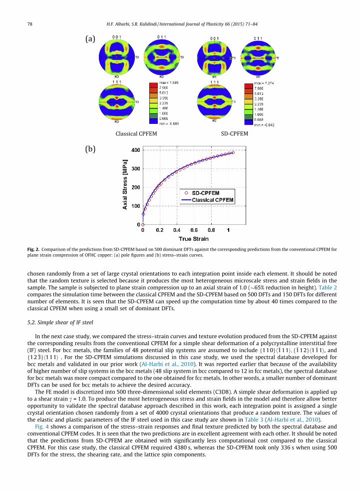
Fig. 2. Comparison of the predictions from SD-CPFEM based on 500 dominant DFTs against the corresponding predictions from the conventional CPFEM forplane strain compression of OFHC copper: (a) pole figures and (b) stress–strain curves.
78 H.F. Alharbi, S.R. Kalidindi / International Journal of Plasticity 66 (2015) 71–84
chosen randomly from a set of large crystal orientations to each integration point inside each element. It should be notedthat the random texture is selected because it produces the most heterogeneous microscale stress and strain fields in thesample. The sample is subjected to plane strain compression up to an axial strain of 1.0 (�65% reduction in height). Table 2compares the simulation time between the classical CPFEM and the SD-CPFEM based on 500 DFTs and 150 DFTs for differentnumber of elements. It is seen that the SD-CPFEM can speed up the computation time by about 40 times compared to theclassical CPFEM when using a small set of dominant DFTs.
5.2. Simple shear of IF steel
In the next case study, we compared the stress–strain curves and texture evolution produced from the SD-CPFEM againstthe corresponding results from the conventional CPFEM for a simple shear deformation of a polycrystalline interstitial free(IF) steel. For bcc metals, the families of 48 potential slip systems are assumed to include f110gh�111i; f�112gh1 �11i, andf12 �3gh111i . For the SD-CPFEM simulations discussed in this case study, we used the spectral database developed forbcc metals and validated in our prior work (Al-Harbi et al., 2010). It was reported earlier that because of the availabilityof higher number of slip systems in the bcc metals (48 slip system in bcc compared to 12 in fcc metals), the spectral databasefor bcc metals was more compact compared to the one obtained for fcc metals. In other words, a smaller number of dominantDFTs can be used for bcc metals to achieve the desired accuracy.
The FE model is discretized into 500 three-dimensional solid elements (C3D8). A simple shear deformation is applied upto a shear strain c = 1.0. To produce the most heterogeneous stress and strain fields in the model and therefore allow betteropportunity to validate the spectral database approach described in this work, each integration point is assigned a singlecrystal orientation chosen randomly from a set of 4000 crystal orientations that produce a random texture. The values ofthe elastic and plastic parameters of the IF steel used in this case study are shown in Table 3 (Al-Harbi et al., 2010).
Fig. 4 shows a comparison of the stress–strain responses and final texture predicted by both the spectral database andconventional CPFEM codes. It is seen that the two predictions are in excellent agreement with each other. It should be notedthat the predictions from SD-CPFEM are obtained with significantly less computational cost compared to the classicalCPFEM. For this case study, the classical CPFEM required 4380 s, whereas the SD-CPFEM took only 336 s when using 500DFTs for the stress, the shearing rate, and the lattice spin components.
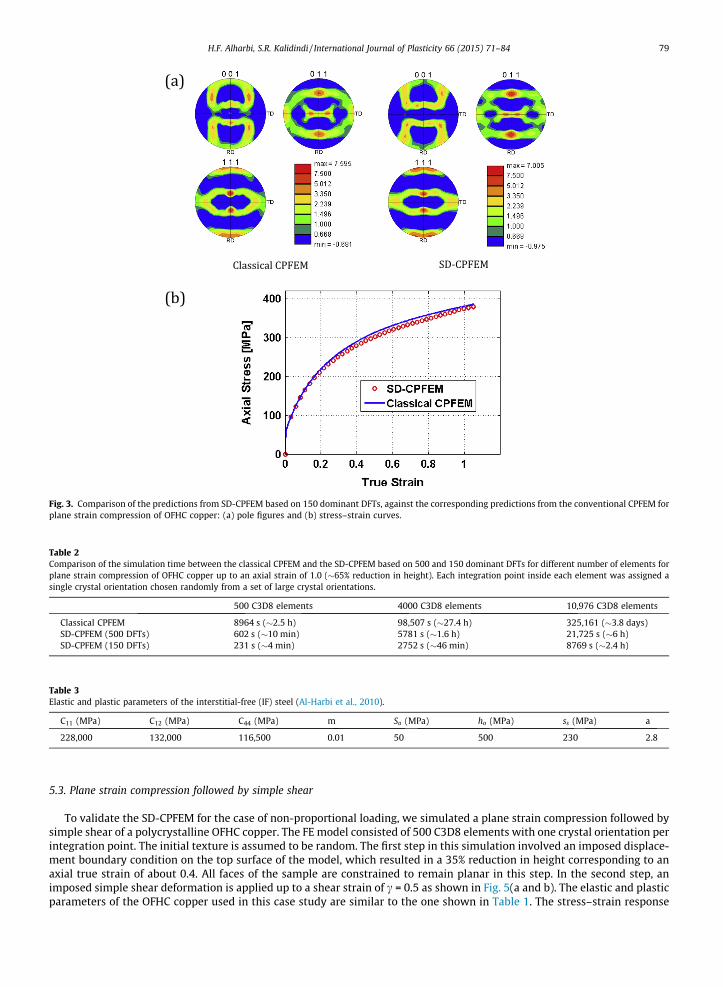
Fig. 3. Comparison of the predictions from SD-CPFEM based on 150 dominant DFTs, against the corresponding predictions from the conventional CPFEM forplane strain compression of OFHC copper: (a) pole figures and (b) stress–strain curves.
Table 2Comparison of the simulation time between the classical CPFEM and the SD-CPFEM based on 500 and 150 dominant DFTs for different number of elements forplane strain compression of OFHC copper up to an axial strain of 1.0 (�65% reduction in height). Each integration point inside each element was assigned asingle crystal orientation chosen randomly from a set of large crystal orientations.
500 C3D8 elements 4000 C3D8 elements 10,976 C3D8 elements
Classical CPFEM 8964 s (�2.5 h) 98,507 s (�27.4 h) 325,161 (�3.8 days)SD-CPFEM (500 DFTs) 602 s (�10 min) 5781 s (�1.6 h) 21,725 s (�6 h)SD-CPFEM (150 DFTs) 231 s (�4 min) 2752 s (�46 min) 8769 s (�2.4 h)
Table 3Elastic and plastic parameters of the interstitial-free (IF) steel (Al-Harbi et al., 2010).
C11 (MPa) C12 (MPa) C44 (MPa) m So (MPa) ho (MPa) ss (MPa) a
228,000 132,000 116,500 0.01 50 500 230 2.8
H.F. Alharbi, S.R. Kalidindi / International Journal of Plasticity 66 (2015) 71–84 79
5.3. Plane strain compression followed by simple shear
To validate the SD-CPFEM for the case of non-proportional loading, we simulated a plane strain compression followed bysimple shear of a polycrystalline OFHC copper. The FE model consisted of 500 C3D8 elements with one crystal orientation perintegration point. The initial texture is assumed to be random. The first step in this simulation involved an imposed displace-ment boundary condition on the top surface of the model, which resulted in a 35% reduction in height corresponding to anaxial true strain of about 0.4. All faces of the sample are constrained to remain planar in this step. In the second step, animposed simple shear deformation is applied up to a shear strain of c = 0.5 as shown in Fig. 5(a and b). The elastic and plasticparameters of the OFHC copper used in this case study are similar to the one shown in Table 1. The stress–strain response

Fig. 4. Comparison of the predictions from SD-CPFEM against the corresponding predictions from the conventional CPFEM for simple shear of interstitial-free (IF) steel: (a) pole figures and (b) stress–strain curves.
Fig. 5. Comparison of the predicted stress–strain curves from the SD-CPFEM against the corresponding results from the conventional CPFEM for planestrain compression followed by simple shear deformation of OFHC copper: (a) mesh after plane strain compression, (b) mesh after simple sheardeformation, and (c) stress–strain curves.
80 H.F. Alharbi, S.R. Kalidindi / International Journal of Plasticity 66 (2015) 71–84
from the SD-CPFEM is compared against the corresponding predictions from the classical CPFEM in Fig. 5(c). The predictedtextures from the two approaches after each deformation step are shown in Fig. 6. It was seen once again that the predictionsfrom the spectral database approach matched very well with the corresponding predictions from the conventional CPFEM ata dramatically reduced computation cost. This prediction took 6380 s for the classical CPFEM and only 527 s for theSD-CPFEM when using 500 DFTs for the stress, the shearing rate, and the lattice spin components.

Fig. 6. Comparison of the predicted texture from the SD-CPFEM against the corresponding predictions from the conventional CPFEM for plane straincompression followed by simple shear deformation of OFHC copper: (a) pole figures after plane strain compression and (b) pole figures after simple sheardeformation.
H.F. Alharbi, S.R. Kalidindi / International Journal of Plasticity 66 (2015) 71–84 81
6. Conclusions
In this paper, we have demonstrated the first integration of our recently developed spectral database approach to crystalplasticity calculations for face centered and body centered cubic polycrystalline metals that deform by crystallographic slipwith the implicit version of the finite element package, ABAQUS, accomplished through the development of a user materialsubroutine, UMAT. For this purpose, we have developed a Newton-type iteration scheme to extend the spectral crystal plas-ticity computations using spectral databases from rigid–viscoplastic to elastic–viscoplastic deformation. We have also estab-lished an efficient analytical expression for the Jacobian required to implement the spectral databases with any implicitfinite element code. The case studies showed that the new spectral crystal plasticity FE approach produces excellent predic-tions similar to the classical crystal plasticity FE method but at a significantly faster computational speed. It was seen thatthe spectral databases implemented in the FE package ABAQUS can speed up the computational time by about 40 times com-pared to the classical CPFEM.
Acknowledgements
This work was partially supported by the National Center for Supercomputing Applications under DMR130087. Theauthors gratefully acknowledge financial support received for this work from NSF Grant CMS-1332417.
Appendix A
We have derived analytical expressions for the Jacobian matrix required for implementing the spectral approach to crys-tal plasticity computations with the FE package ABAQUS. Below is a brief description of the derivation of the term @r0
@Dp usingthe chain rule:

(1)
(2)
(3)
82 H.F. Alharbi, S.R. Kalidindi / International Journal of Plasticity 66 (2015) 71–84
@r0
@Dp¼@r0
@ _e
����h;uD
1 ;UD ;uD
2
@ _e@Dp
!þ @r0
@h
����_e;uD
1 ;UD ;uD
2
@h
@Dp
!þ @r0
@uD1
����h; _e;UD ;uD
2
@uD1
@Dp
!þ @r0
@UD
����h; _e;uD
1 ;uD2
@UD
@Dp
!þ @r0
@uD2
����h; _e;uD
1;UD
@uD2
@Dp
!" #ðA1Þ
For simplicity of notation, the above relation will be expressed in a condensed form as
@r0
@Dp ¼@r0
@ _e
����h;gD
@ _e@Dp
!þ @r0
@h
����_e;gD
@h
@Dp
!þ @r0
@gD
����_e;h
@gD
@Dp
!" #ðA2Þ
where gD ¼ ðuD1 ;U
D;uD2 Þ denotes the set of three Bunge–Euler angles that describe the orientation matrix ½QD� used to trans-
form the deviatoric stress tensor from the principle frame of Dp fepi g into the sample frame fes
ig.Recall that the deviatoric stress tensor is calculated using the spectral approach (see Eq. (11)) as
r0ðPrÞrq ðh; _e; gpÞ ¼ s _em 1
Ngp Nh
Xk
Xn
Ckne2pikrNgp e
2pinqNh ðA3Þ
where the superscript (Pr) indicates that the stress values are defined in the principal frame of Dp. This stress tensor can betransformed to the sample frame using the second-rank transformation
r0ðDp; gÞ ¼ ½Q D�½r0ðPrÞðh; _e; gpÞ�½Q D�T ðA4Þ
where g denotes the crystal lattice orientation defined using the Bunge–Euler angles ðu1;/;u2Þ (Bunge, 1993). It should benoted that the Bunge–Euler angles gp; g; and gD are not independent of each other. In fact, one can readily show
½Q p� ¼ ½Q D�T½Q � ðA5Þ
where ½Qp� is the orientation matrix that brings the crystal frame feci g into coincidence with the principal frame of
Dp; i:e: fepi g , and ½Q � is the rotation matrix that relates the crystal frame fec
i g to the sample frame fesig. These orientation
matrices can be calculated using their respective three Bunge–Euler angles. For example, the rotation matrix ½Q � is given by
½Q � ¼cos u1 cos u2 � sin u1 sin u2 cos U � cos u1 sinu2 � sin u1 cos u2 cos U sin u1 sin U
sinu1 cos u2 þ cos u1 sin u2 cos U � sinu1 sinu2 þ cos u1 cos u2 cos U � cos u1 sin U
sinu2 sin U cos u2 sin U cos U
264375 ðA6Þ
Using the above relations, the analytical expressions for each of the term in Eq. (A2) can be derived as follows (for sim-plicity, assume that there is no strain hardening, i.e. s is constant in Eq. (A3)):
@r0
@ _e
����h;gD
¼ms_e½QD�½r0ðPrÞ�½Q D�T ðA7Þ
@r0
@h
����_e;gD
¼ ½Q D� @r0ðPrÞ
@h
�½QD�T ðA8Þ
where
@r0ðPrÞrq
@h¼ s _em 1
Ngp Nh
Xk
Xn
eCkne2pikrNgp e
2pinqNh ; eCkn ¼ 2p in Ckn ðA9Þ
It is clear that the spectral representation presented in this work allows efficient calculation of the term@r0ðPrÞ
rq
@h .
@h
@Dp ¼@h@D1
@D1
@Dp ðA10Þ
where D1 is the first eigenvalue of Do (see Eq. (9)). The term @h@D1
is calculated directly from Eq. (9) and an analytical expressionof @D1
@Dp is derived using the determinant of Do defined as
detðDoÞ ¼ det1_e
Dp� �
¼ D1D2D3 ¼ D31 �
12
D1 ðA11Þ
(4) The computation of the term @r0
@gD
���_e;h
involves the calculations of the derivatives @½QD �@gD and @r0ðPrÞ
@gD (see Eq. (A4)): !
@r0@gD j _e;h ¼ f@½Q D�@gD ;
@r0ðPrÞ
@gD ðA12Þ
H.F. Alharbi, S.R. Kalidindi / International Journal of Plasticity 66 (2015) 71–84 83
where
@r0ðPrÞ
@gD ¼ @r0ðPrÞ
@gp
@gp
@gD ðA13Þ
The term @r0ðPrÞ
@gp is calculated using an expression similar to Eq. (A9) and @gp
@gD is derived using Eq. (A5). Furthermore, the term @½QD �@gD
in Eq. (A12) is calculated using Eq. (A6).(5) The term @gD
@Dp is calculated using the relation
DpNðiÞ ¼ kNðiÞ ðA14Þ
where NðiÞ denotes the column i of ½QD�, which represents the eigenvector of Dp corresponding to the eigenvalue k. To avoidthe additional calculations of evaluating the derivative of the eigenvalues with respect to Dp, we use the orthogonality prop-erty of the eigenvectors and rewrite Eq. (A14) as
DpNðiÞ � NðjÞ ¼ kNðiÞ �NðjÞ ¼ 0 for i–j ðA15Þ
Then, the term @gD
@Dp can be readily calculated using Eqs. (A15) and (A6).
To validate the methods described above for deriving each of the term, we compared the values produced from the finalexpressions of these terms with the corresponding values computed numerically by slightly perturbing the independent var-iable in each expression.
References
ABAQUS, 2010. � Dassault Systèmes Simulia Corp., Providence, RI, USA.Al-Harbi, H.F., Knezevic, M., Kalidindi, S.R., 2010. Spectral approaches for the fast computation of yield surfaces and first-order plastic property closures for
polycrystalline materials with cubic–triclinic textures. CMC – Comput. Mater. Continua 15, 153–172.Asaro, R.J., Needleman, A., 1985a. Overview no. 42 texture development and strain hardening in rate dependent polycrystals. Acta Metall. 33, 923–953.Asaro, R.J., Needleman, A., 1985b. Texture development and strain hardening in rate dependent polycrystals. Acta Metall. Mater. 33, 923–953.Bachu, V., Kalidindi, S.R., 1998. On the accuracy of the predictions of texture evolution by the finite element technique for fcc polycrystals. Mater. Sci. Eng. A
– Struct. Mater. Prop. Microstruct. Process. 257, 108–117.Bhattacharyya, A., El-Danaf, E., Kalidindi, S.R., Doherty, R.D., 2001. Evolution of grain-scale microstructure during large strain simple compression of
polycrystalline aluminum with quasi-columnar grains: OIM measurements and numerical simulations. Int. J. Plasticity 17, 861–883.Bridier, F., McDowell, D.L., Villechaise, P., Mendez, J., 2009. Crystal plasticity modeling of slip activity in Ti–6Al–4V under high cycle fatigue loading. Int. J.
Plasticity 25, 1066–1082.Bronkhorst, C.A., Kalidindi, S.R., Anand, L., 1992a. Polycrystalline plasticity and the evolution of crystallographic texture in fcc metals. Philos. Trans. Roy. Soc.
Lond. Ser. A – Math. Phys. Eng. Sci. 341, 443–477.Bronkhorst, C.A., Kalidindi, S.R., Anand, L., 1992b. Polycrystalline plasticity and the evolution of crystallographic texture in FCC metals. Philos. Trans. Roy.
Soc. Lond. Ser. A – Math. Phys. Eng. Sci. 341, 443–477.Brown, S.B., Kim, K.H., Anand, L., 1989. An internal variable constitutive model for hot working of metals. Int. J. Plasticity 5, 95–130.Bunge, H.-J., 1993. Texture Analysis in Materials Science. Mathematical Methods, Cuvillier Verlag, Göttingen.Choi, S.H., Kim, D.W., Seong, B.S., Rollett, A.D., 2011. 3-D simulation of spatial stress distribution in an AZ31 Mg alloy sheet under in-plane compression. Int.
J. Plasticity 27, 1702–1720.Delaire, F., Raphanel, J.L., Rey, C., 2000. Plastic heterogeneities of a copper multicrystal deformed in uniaxial tension: experimental study and finite element
simulations. Acta Mater. 48, 1075–1087.Delannay, L., Kalidindi, S.R., Van Houtte, P., 2002. Quantitative prediction of textures in aluminium cold rolled to moderate strains. Mater. Sci. Eng. A 336,
233–244.Erieau, P., Rey, C., 2004. Modeling of deformation and rotation bands and of deformation induced grain boundaries in IF steel aggregate during large plane
strain compression. Int. J. Plasticity 20, 1763–1788.Garmestani, H., Kalidindi, S.R., Williams, L., Bacaltchuk, C.M., Fountain, C., Lee, E.W., Es-Said, O.S., 2002. Modeling the evolution of anisotropy in Al–Li alloys:
application to Al–Li 2090–T8E41. Int. J. Plasticity 18, 1373–1393.Goh, C.-H., Neu, R.W., McDowell, D.L., 2003. Crystallographic plasticity in fretting of Ti–6AL–4V. Int. J. Plasticity 19, 1627–1650.Héripré, E., Dexet, M., Crépin, J., Gélébart, L., Roos, A., Bornert, M., Caldemaison, D., 2007. Coupling between experimental measurements and polycrystal
finite element calculations for micromechanical study of metallic materials. Int. J. Plasticity 23, 1512–1539.Hosford, W.F., Caddell, R.M., 1993. Metal Forming Mechanics and Metallurgy. Prentice-Hall Inc.Hutchinson, J.W., 1976. Bounds and self-consistent estimates for creep of polycrystalline materials. Proc. Roy. Soc. Lond. A. Math. Phys. Sci. 348, 101–127.Kalidindi, S.R., Anand, L., 1994. Macroscopic shape change and evolution of crystallographic texture in pre-textured fcc metals. J. Mech. Phys. Solids 42, 459–
490.Kalidindi, S.R., Schoenfeld, S.E., 2000. On the prediction of yield surfaces by the crystal plasticity models for fcc polycrystals. Mater. Sci. Eng. A – Struct.
Mater. Prop. Microstruct. Process. 293, 120–129.Kalidindi, S.R., Bronkhorst, C.A., Anand, L., 1992. Crystallographic texture evolution in bulk deformation processing of FCC metals. J. Mech. Phys. Solids 40,
537–569.Kalidindi, S.R., Bhattacharyya, A., Doherty, R.D., 2004. Detailed analyses of grain–scale plastic deformation in columnar polycrystalline aluminium using
orientation image mapping and crystal plasticity models. Proc. Roy. Soc. Lond. Ser. A: Math., Phys. Eng. Sci. 460, 1935–1956.Kalidindi, S.R., Duvvuru, H.K., Knezevic, M., 2006. Spectral calibration of crystal plasticity models. Acta Mater. 54, 1795–1804.Kalidindi, S.R., Knezevic, M., Niezgoda, S., Shaffer, J., 2009. Representation of the orientation distribution function and computation of first-order elastic
properties closures using discrete Fourier transforms. Acta Mater. 57, 3916–3923.Kanjarla, A.K., Van Houtte, P., Delannay, L., 2010. Assessment of plastic heterogeneity in grain interaction models using crystal plasticity finite element
method. Int. J. Plasticity 26, 1220–1233.Knezevic, M., Kalidindi, S.R., Fullwood, D., 2008. Computationally efficient database and spectral interpolation for fully plastic Taylor-type crystal plasticity
calculations of face-centered cubic polycrystals. Int. J. Plasticity 24, 1264–1276.Knezevic, M., Al-Harbi, H.F., Kalidindi, S.R., 2009. Crystal plasticity simulations using discrete Fourier transforms. Acta Mater. 57, 1777–1784.Kocks, U.F., Mecking, H., 2003. Physics and phenomenology of strain hardening: the FCC case. Prog. Mater. Sci. 48, 171–273.Lebensohn, A., 2001. N-site modeling of a 3D viscoplastic polycrystal using fast Fourier transform. Acta Mater. 49, 2723–2737.

84 H.F. Alharbi, S.R. Kalidindi / International Journal of Plasticity 66 (2015) 71–84
Lebensohn, R.A., Tomé, C.N., 1993. A self-consistent anisotropic approach for the simulation of plastic deformation and texture development of polycrystals:application to zirconium alloys. Acta Metall. Mater. 41, 2611–2624.
Lebensohn, R.A., Dawson, P.R., Kern, H.M., Wenk, H.-R., 2003. Heterogeneous deformation and texture development in halite polycrystals: comparison ofdifferent modeling approaches and experimental data. Tectonophysics 370, 287–311.
Lebensohn, R.A., Liu, Y., Ponte Castañeda, P., 2004. On the accuracy of the self-consistent approximation for polycrystals: comparison with full-fieldnumerical simulations. Acta Mater. 52, 5347–5361.
Lebensohn, R.A., Tome, C.N., Castaneda, P.P., 2007. Self-consistent modelling of the mechanical behaviour of viscoplastic polycrystals incorporatingintragranular field fluctuations. Philos. Mag. 87, 4287–4322.
Lebensohn, R.A., Brenner, R., Castelnau, O., Rollett, A.D., 2008. Orientation image-based micromechanical modelling of subgrain texture evolution inpolycrystalline copper. Acta Mater. 56, 3914–3926.
Liu, Y.S., Delannay, L., Van Houtte, P., 2002. Application of the Lamel model for simulating cold rolling texture in molybdenum sheet. Acta Mater. 50, 1849–1856.
Liu, B., Raabe, D., Roters, F., Eisenlohr, P., Lebensohn, R.A., 2010. Comparison of finite element and fast Fourier transform crystal plasticity solvers for textureprediction. Modell. Simul. Mater. Sci. Eng. 18, 085005.
Luo, M., Rousselier, G., 2014. Modeling of large strain multi-axial deformation of anisotropic metal sheets with strength-differential effect using a ReducedTexture Methodology. Int. J. Plasticity 53, 66–89.
Mayeur, J.R., McDowell, D.L., 2007. A three-dimensional crystal plasticity model for duplex Ti–6Al–4V. Int. J. Plasticity 23, 1457–1485.Mayeur, J.R., McDowell, D.L., Neu, R.W., 2008. Crystal plasticity simulations of fretting of Ti–6Al–4V in partial slip regime considering effects of texture.
Comput. Mater. Sci. 41, 356–365.McDowell, D.L., 2010. A perspective on trends in multiscale plasticity. Int. J. Plasticity 26, 1280–1309.Molinari, A., Canova, G.R., Ahzi, S., 1987. A self consistent approach of the large deformation polycrystal viscoplasticity. Acta Metall. 35, 2983–2994.Musienko, A., Tatschl, A., Schmidegg, K., Kolednik, O., Pippan, R., Cailletaud, G., 2007. Three-dimensional finite element simulation of a polycrystalline
copper specimen. Acta Mater. 55, 4121–4136.Needleman, A., Asaro, R.J., Lemonds, J., Peirce, D., 1985. Finite element analysis of crystalline solids. Comput. Methods Appl. Mech. Eng. 52, 689–708.Pan, J., Rice, J.R., 1983. Rate sensitivity of plastic flow and implications for yield-surface vertices. Int. J. Solids Struct. 19, 973–987.Peirce, D., Asaro, R.J., Needleman, A., 1982. An analysis of nonuniform and localized deformation in ductile single crystals. Acta Metall. 30, 1087–1119.Peirce, D., Asaro, R.J., Needleman, A., 1983. Material rate dependence and localized deformation in crystalline solids. Acta Metall. 31, 1951–1976.Prakash, A., Lebensohn, R.A., 2009. Simulation of micromechanical behavior of polycrystals: finite elements versus fast Fourier transforms. Modell. Simul.
Mater. Sci. Eng. 17, 064010.Raabe, D., Roters, F., 2004. Using texture components in crystal plasticity finite element simulations. Int. J. Plasticity 20, 339–361.Raabe, D., Zhao, Z., Roters, F., 2001. A finite element method on the basis of texture components for fast predictions of anisotropic forming operations. Steel
Res. 72, 421–426.Raabe, D., Zhao, Z., Mao, W., 2002. On the dependence of in-grain subdivision and deformation texture of aluminum on grain interaction. Acta Mater. 50,
4379–4394.Raabe, D., Zhao, Z., Roters, F., 2004. Study on the orientational stability of cube-oriented FCC crystals under plane strain by use of a texture component
crystal plasticity finite element method. Scripta Mater. 50, 1085–1090.Raabe, D., Wang, Y., Roters, F., 2005. Crystal plasticity simulation study on the influence of texture on earring in steel. Comput. Mater. Sci. 34, 221–234.Rousselier, G., Luo, M., Mohr, D., 2012. Macroscopic plasticity modeling of anisotropic aluminum extrusions using a reduced texture methodology. Int. J.
Plasticity 30–31, 144–165.Sachtleber, M., Zhao, Z., Raabe, D., 2002. Experimental investigation of plastic grain interaction. Mater. Sci. Eng., A 336, 81–87.St-Pierre, L., Héripré, E., Dexet, M., Crépin, J., Bertolino, G., Bilger, N., 2008. 3D simulations of microstructure and comparison with experimental
microstructure coming from O.I.M analysis. Int. J. Plasticity 24, 1516–1532.Suquet, P., Moulinec, H., Castelnau, O., Montagnat, M., Lahellec, N., Grennerat, F., Duval, P., Brenner, R., 2012. Multi-scale modeling of the mechanical
behavior of polycrystalline ice under transient creep. Proc. IUTAM 3, 76–90.Taylor, 1938. Plastic Strain in Metals.Tikhovskiy, I., Raabe, D., Roters, F., 2007. Simulation of earing during deep drawing of an Al–3% Mg alloy (AA 5754) using a texture component crystal
plasticity FEM. J. Mater. Process. Technol. 183, 169–175.Van Houtte, P., 1994. Application of plastic potentials to strain rate sensitive and insensitive anisotropic materials. Int. J. Plasticity 10, 719–748.Van Houtte, P., Delannay, L., Kalidindi, S.R., 2002. Comparison of two grain interaction models for polycrystal plasticity and deformation texture prediction.
Int. J. Plasticity 18, 359–377.Van Houtte, P., Li, S., Seefeldt, M., Delannay, L., 2005. Deformation texture prediction: from the Taylor model to the advanced Lamel model. Int. J. Plasticity
21, 589–624.Van Houtte, P., Kanjarla, A.K., Van Bael, A., Seefeldt, M., Delannay, L., 2006. Multiscale modelling of the plastic anisotropy and deformation texture of
polycrystalline materials. Eur. J. Mech. A. Solids 25, 634–648.Zhao, Z., Ramesh, M., Raabe, D., Cuitiño, A.M., Radovitzky, R., 2008. Investigation of three-dimensional aspects of grain-scale plastic surface deformation of
an aluminum oligocrystal. Int. J. Plasticity 24, 2278–2297.
Top Related