


Languages
Pages
Legal


International Institute of Ammonia Refrigeration
www.iiar.org
Member of
Bulletin 802C
©2004 EVAPCO, Inc.
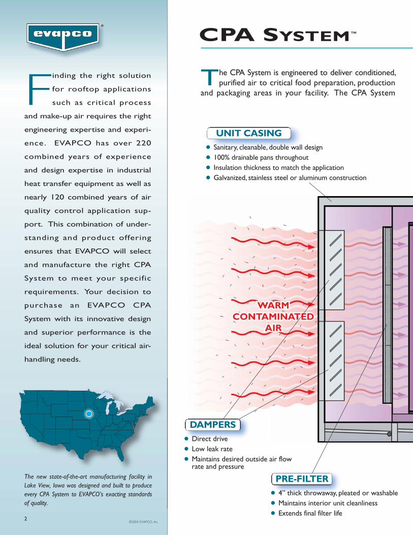
The CPA System is engineered to deliver conditioned,purified air to critical food preparation, production
and packaging areas in your facility. The CPA SystemFinding the right solution
for rooftop applications
such as critical process
and make-up air requires the right
engineering expertise and experi-
ence. EVAPCO has over 220
combined years of experience
and design expertise in industrial
heat transfer equipment as well as
nearly 120 combined years of air
quality control application sup-
port. This combination of under-
standing and product offering
ensures that EVAPCO will select
and manufacture the right CPA
System to meet your specific
requirements. Your decision to
purchase an EVAPCO CPA
System with its innovative design
and superior performance is the
ideal solution for your critical air-
handling needs.
The new state-of-the-art manufacturing facility inLake View, Iowa was designed and built to produceevery CPA System to EVAPCO’s exacting standardsof quality.
● 4” thick throwaway, pleated or washable● Maintains interior unit cleanliness● Extends final filter life
PRE-FILTER
● Sanitary, cleanable, double wall design● 100% drainable pans throughout● Insulation thickness to match the application● Galvanized, stainless steel or aluminum construction
UNIT CASING
● Direct drive● Low leak rate● Maintains desired outside air flow
rate and pressure
DAMPERS
CPA SYSTEM™
2
®

INNOVATIVE DESIGN • SUPERIOR PERFORMANCE
● Standard construction includes ST Series Finned Coil Technology–304L stainless steel tube/aluminum fins
● Optional copper tube/aluminum finnedor all stainless steel coils are available
● High heat transfer efficiency
COOLING COIL
● UVC germicidal light system● Virtually eliminates air contaminants● Preserves coil cleanliness● Eliminates manual coil cleaning
ESS™
● Steam● Brine/glycol● Hot gas● Natural gas or propane
AIR HEATING
● 95% (1 micron) to 99.99%HEPA filters (0.1 microns)
● Controls discharge air purity
FINAL FILTERS
● Low sound● High capacity/efficiency● TEFC fan motor● Plenum type centrifugal fan
FAN SECTION
● Complete, project specific control systems available
● Stand alone DDC or PLC● Integration with plant systems● Fully tested prior to shipment
CONTROLS
3
includes patented technology to provide maximum thermal efficiencies, air purification/filtrationto meet stringent air quality standards, and control packages to monitor and actuate the functionsof the critical process unit.

SUPERIOR HYGIENE AND PERFORMANCE THROUGH INNOVATIVE DESIGN
STATE OF THE ART CONTAMINANT
CONTROL: ESS™ TECHNOLOGY
Specifying the EVAPCO Sanitizing System (ESS™) with yourCPA System will virtually eliminate hazardous bioaerosolsfrom the cooling coil/pan, resulting in hygienically clean air andimproved product quality while maintaining system perform-ance and significantly reducing annual maintenance costs.
● Provides FullGermicidal Effect atLow Air Temperatures
● Greater than SevenTimes the Effect of aStandard UV Bulb
● Destroys Byproductsfrom Mold andBacteria
● Lower Operating andMaintenance Costs
Including the ESS™ with your CPA System will ensure effectivecleaning of the cooling coil and pan, as well as provide contin-uous cool clean air to your critical food processing areas.
CPA SYSTEMS –THE IDEAL SOLUTION
Superior Cleanliness• The industry’s most sanitary enclosure design that mini-
mizes fastener heads on the interior walls and ceiling.
• The “100% free flow” drain pan eliminates stagnant water.
• Optional 304 stainless steel interior enclosure panelconstruction.
Lower Operating and Maintenance Costs• EVAPCO ST Series Finned Coil results in the lowest fan
horsepower.
• Specifying the ESS will maintain the evaporator coil in“like new” condition which yields optimum heat transferefficiency and maintains design air flow.
• The ESS will provide cleaner interior surfaces which willextend the life of the final filters.
• The ESS virtually eliminates the need for cleaning equip-ment, solutions, chemicals and labor.
Standard Construction Features• Unique, double wall enclosure panels.
• EVAPCO ST Series, heavy wall finned coils manufac-tured per ASME/ANSI B31.5 and factory charged withnitrogen.
• Heavy gauge G-235 mill hot dip galvanized steel compo-nents for superior corrosion protection.
SUPERIOR PERFORMANCE:“ST SERIES” FINNED COILS
Standard cooling coils in CPA Systems® are constructedwith EVAPCO “ST Series” finned coil technology utilizingtype 304L stainless steel tube and aluminum fins.
● Round, Heavy Wall Tubes Manufactured by EVAPCOResult in Consistent Tube Quality and Availability
● Standard 1.05” Diameter Stainless Steel Tube
● Tube & Fin Spacing for Maximum Performance andSuperior Hygiene
● Tube Material Meets B31.5 Refrigerant Piping CodeRequirement
● Hydraulically Expanded for Consistent Tube to Fin CollarContact
● Entire Coil is Pressure Tested to 400 psig
● Optional 5/8” Diameter Stainless Steel or Copper TubeAvailable
The ST Series finned coil technology is the result of exten-sive Research & Development where it was thoroughlytested in EVAPCO’s Low Temperature Environmental TestChamber.
4
STATE OF THE ART CONTAMINANT
CONTROL: ESS™ TECHNOLOGY

2.3
12
243849
74
99
123
149
185
222
248
297
343
369
428
4.5 6.8 9.0 13.5 18.0 22.5 27.0 33.8 40.5 45.0 54.0 63.0 67.5 78.8
AIRFLOW RANGE (CFM IN THOUSANDS)
NO
MIN
AL
CO
OL
ING
CA
PAC
ITY
(TO
NS)
2 (2
/3/3
)*
4 (5
/5/5
)
6 (5
/7.5
/7.5
)
8 (7
.5/1
0/10
)
12 (
10/1
5/15
)
16 (
15/2
0/15
)
20 (
20/2
0/2
0)
24 (
20/2
5/2
5) 30 (
25/3
0/3
0)
36 (
30/4
0/4
0)
40 (
40/4
0/4
0)
48 (
40/5
0/5
0)
56 (
50/6
0/6
0)
60 (
50/7
5/6
0)
70 (
60/1
00/7
5)
NOTES:1. Nominal cooling capacities are based on 75°F entering air dry bulb temperature; 35°F saturated suction temperature; 12 rows, 8 FPI, stainless steel tube/aluminum fin coil.2. To obtain nominal cooling capacities for a CPA model with 99.97% HEPA final filter efficiency, multiply the associated model capacity shown above by 0.8. Air flow
rates for these models are at the lowest value indicated.3. To obtain nominal cooling capacities for a 50°F entering air dry bulb temperature and 30°F saturated suction temperature, multiply the associated model capacity
shown above by 0.5.4. Information shown above is for estimating purposes only and subject to change without notice. * Numbers in parentheses represent nominal fan motor horsepowers.
Critical Process Air Unit Nominal Airflow (CFM in thousands) Highest Filter Efficiency
CPA SYSTEM PERFORMANCE DATA
5
MODEL NUMBER NOMENCLATURECPA-24-95
To formulate your critical process air model number, begin with the designation “CPA”, followed by the nominal airflow (boldface number abovebar), and end with the highest filter efficiency value (i.e. 30, 95 or 99). A standard feature for all CPA models is pre-filters, with 30% efficiency.When final filters are required, their associated efficiency (95 or 99) is shown at the end of the model number (see above example).

6
CPA SYSTEM™ COOLING AND HEATING
NOMINAL CAPACITIES
Notes:1. Nominal cooling capacities are based on 75°F entering air dry bulb temperature; 35°F saturated suction temperature; 12 rows, 8 FPI, stainless steel tube/aluminum fin coil.2. Nominal cooling capacities are based on 50°F entering air dry bulb temperature; 30°F saturated suction temperature; 12 rows, 8 FPI, stainless steel tube/aluminum fin coil.3. Capacities are based on a 90°F temperature rise through the heating system.4. Information shown above is for estimating purposes only and subject to change without notice.
Nominal Nominal NominalModel Air Flow Range Pre-filter Final Filter Motor Cooling Cooling Heating
Efficiency Efficiency H.P. Capacity (1) Capacity (2) Capacity (3)
CPA-2-30 2,000 - 2,500 30% N/A 2 12.1 5.6 244
CPA-4-30 4,000 - 5,000 30% N/A 5 24.4 11.3 486
CPA-6-30 6,000 - 7,500 30% N/A 5 37.6 17.4 730
CPA-8-30 8,000 - 10,000 30% N/A 7.5 49.4 22.9 972
CPA-12-30 12,000 - 15,000 30% N/A 10 74.1 34.3 1458
CPA-16-30 16,000 - 20,000 30% N/A 15 98.6 45.6 1944
CPA-20-30 20,000 - 25,000 30% N/A 20 122.5 56.7 2430
CPA-24-30 24,000 - 30,000 30% N/A 20 148.5 68.7 2916
CPA-30-30 30,000 - 37,500 30% N/A 25 185.1 85.7 3646
CPA-36-30 36,000 - 45,000 30% N/A 30 222.2 102.8 4374
CPA-40-30 40,000 - 50,000 30% N/A 40 248.3 114.9 4860
CPA-48-30 48,000 - 60,000 30% N/A 40 297.3 137.6 5832
CPA-56-30 56,000 - 70,000 30% N/A 50 343.4 158.9 6804
CPA-60-30 60,000 - 75,000 30% N/A 50 369.1 170.8 7290
CPA-70-30 70,000 - 87,500 30% N/A 60 427.8 198.0 8506
CPA-2-95 2,000 - 2,500 30% 95% 3 12.1 5.6 244
CPA-4-95 4,000 - 5,000 30% 95% 5 24.4 11.3 486
CPA-6-95 6,000 - 7,500 30% 95% 7.5 37.6 17.4 730
CPA-8-95 8,000 - 10,000 30% 95% 10 49.4 22.9 972
CPA-12-95 12,000 - 15,000 30% 95% 15 74.1 34.3 1458
CPA-16-95 16,000 - 20,000 30% 95% 20 98.6 45.6 1944
CPA-20-95 20,000 - 25,000 30% 95% 20 122.5 56.7 2430
CPA-24-95 24,000 - 30,000 30% 95% 25 148.5 68.7 2916
CPA-30-95 30,000 - 37,500 30% 95% 30 185.1 85.7 3646
CPA-36-95 36,000 - 45,000 30% 95% 40 222.2 102.8 4374
CPA-40-95 40,000 - 50,000 30% 95% 40 248.3 114.9 4860
CPA-48-95 48,000 - 60,000 30% 95% 50 297.3 137.6 5832
CPA-56-95 56,000 - 70,000 30% 95% 60 343.4 158.9 6804
CPA-60-95 60,000 - 75,000 30% 95% 75 369.1 170.8 7290
CPA-70-95 70.000 - 87,500 30% 95% 100 427.8 198.0 8506
CPA-2-99 2,000 30% 99.97% 3 10.0 4.6 196
CPA-4-99 4,000 30% 99.97% 5 19.6 9.1 389
CPA-6-99 6,000 30% 99.97% 7.5 30.4 14.1 584
CPA-8-99 8,000 30% 99.97% 10 40.2 18.6 778
CPA-12-99 12,000 30% 99.97% 15 60.5 28.0 1166
CPA-16-99 16,000 30% 99.97% 15 80.5 37.3 1555
CPA-20-99 20,000 30% 99.97% 20 99.0 45.8 1944
CPA-24-99 24,000 30% 99.97% 25 119.7 55.4 2333
CPA-30-99 30,000 30% 99.97% 30 149.6 69.2 2917
CPA-36-99 36,000 30% 99.97% 40 180.1 83.4 3499
CPA-40-99 40,000 30% 99.97% 40 202.2 93.6 3888
CPA-48-99 48,000 30% 99.97% 50 240.1 111.1 4666
CPA-56-99 56,000 30% 99.97% 60 278.1 128.7 5443
CPA-60-99 60,000 30% 99.97% 60 297.9 137.9 5832
CPA-70-99 70,000 30% 99.97% 75 348.3 161.2 6805

7
CPA SYSTEM™ BASE UNIT
DIMENSIONAL DATA
Model A B C D E F G H L M P Q R
CPA-2-95/99 175 56-1/4 50 - - 24 16 24 24 12 12 12 29
CPA-4-95/99 183 64-1/4 50 - - 48 8 24 48 12 12 12 29
CPA-6-95/99 183 80-1/4 50 - - 72 4 24 60 14 18 15 40-1/2
CPA-8-95/99 190 80-1/4 72 - - 48 16 48 48 24 18 18 40-1/2
CPA-12-95/99 216 98-1/4 72 108 108 72 13 48 72 24 24 22 52-1/2
CPA-16-95/99 216 118-1/4 72 108 108 96 11 48 96 24 24 22 52-1/2
CPA-20-95/99 222 134-1/4 87 118 114 120 7 48 96 30 24 22 78
CPA-24-95/99 222 134-1/4 93 108 114 96 19 72 108 32 24 22 78
CPA-30-95/99 234 148-1/4 99 114 120 120 14 72 128 32 24 30 78
CPA-36-95/99 234 162-1/4 105 114 120 144 9 72 138 38 16 39 89
CPA-40-95/99 246 162-1/4 116 114 132 120 21 96 138 42 16 39 89
CPA-48-95/99 246 162-1/4 134 114 132 144 9 96 138 48 18 42 99
CPA-56-95/99 252 188.25 138 120 132 168 10 96 144 50 18 42 99
CPA-60-95/99 264 200 138 120 144-1/4 168 16 108 160 50 18 42 99
CPA-70-95/99 264 220 138 120 144-1/4 192 14 108 180 50 18 42 99
LO/A & R/A
G
ACCESSDOORS
(4) REMOVABLE LIFTINGLUGS PER SECTION
FS/A
G
1-1/2" IPS DRAINS CONTROL PANEL
OUTSIDE AIRINLET HOOD
W/BIRDSCREEN(SHIPPEDLOOSE)
R
MO/A
R/A DAMPERM X L
O/A DAMPERM X L
PREFILTERS
5"H
S/A
MR/A
�y��yy
P
Q D
A
E 8" BASE
12" HIGH BASEON 56 – 70 UNITS�
�yy
��yy
��yy B
FINALFILTERS
1-1/2" ROOF PITCH ON CPA 12 – 70 ON 56 – 70 UNITSROOF PITCHBOTH WAYS
COOLINGCOIL
HEATINGCOIL
PLENUM FANW/MOTOR
C
1-5/8" ROOF SEAM
RAIN GUARD ABOVE DOOR
PLAN VIEW
ELEVATION VIEW S/A ENDVIEW

CPA SYSTEM™ BASE UNIT WITH INTEGRAL EXHAUST
DIMENSIONAL DATA
8
Model A B C D E F G J M N Q S T U V W X Y
CPA-2-95/99 260 80-1/4 73-1/2 130 - 130 24 24 12 12 24 1 24 1/2 40-1/4 - 24 16
CPA-4-95/99 260 80-1/4 73-1/2 130 - 130 48 24 14 14 44 1 24 3/4 40-1/4 - 24 16
CPA-6-95/99 260 80-1/4 73-1/2 130 - 130 72 24 20 20 44 1 24 1-1/2 40-1/4 - 24 22
CPA-8-95/99 260 80-1/4 73-1/2 130 - 130 48 48 28 28 44 1 30 1-1/2 40-1/4 - 24 22
CPA-12-95/99 291 98-1/4 73-1/2 100 110 81 72 48 38 38 44 1 36 3 49-1/4 - 24 22
CPA-16-95/99 294 118-1/4 73-1/2 100 110 84 96 48 42 42 54 1 42 3 61-1/4 24 24 32
CPA-20-95/99 300 134-1/4 94-1/2 100 110 90 120 48 48 48 60 2 30 2 61-1/4 24 24 32
CPA-24-95/99 300 134-1/4 94-1/2 100 110 90 96 72 48 48 72 2 30 5 61-1/4 24 24 42
CPA-30-95/99 300 148-1/4 100-1/2 100 110 90 120 72 56 56 72 2 30 5 73 30 30 36
CPA-36-95/99 310 162-1/4 117-1/2 100 110 100 144 72 60 60 72 2 36 5 73 30 30 42
CPA-40-95/99 318 162-1/4 117-1/2 100 110 108 120 96 60 60 96 2 42 5 81 24 24 36
CPA-48-95/99 318 162-1/4 135-1/2 100 110 108 144 96 60 60 110 2 42 5 81 30 30 42
CPA-56-95/99 340 188-1/4 139-1/2 110 110 120 168 96 66 66 110 2 42 7-1/2 94 30 30 48
CPA-60-95/99 340 200 139-1/2 110 110 120 168 108 72 72 110 2 48 7-1/2 100 30 30 54
CPA-70-95/99 340 220 139-1/2 110 110 120 192 108 82 82 110 2 48 10 110 30 30 60
X
V
W ACCESSDOORS
1-1/2" IPS DRAINS CONTROLCABINET
GS/A
O/AINLET HOOD
W/BIRDSCREEN(SHIPPEDLOOSE)
JS/A
8" BASE12" HIGHBASE ON56 – 70UNITS
B
��yy
��yy
1-1/2"PITCH
QO/AR/A
N O/A
C
PLAN VIEW
Y D
A
E F
ELEVATION VIEW
BURNER
R/ADAMPER
CLEAN-UPEXHAUST
PIPINGCABINET
O/A
R/A
(4) REMOVABLE LIFTINGLUGS PER SECTION
D/A DAMPERN X Q
(2) BACKDRAFTDAMPERS PER FAN
ON 56 – 70UNITSROOFPITCHBOTHWAYS
COOLINGCOIL
PLENUM FANW/MOTOR FINAL
FILTERSPREFILTERS
M R/A
O/A & R/A END VIEW(SHOWN WITHOUT HOOD)
(S) T" EXHAUST FANSW/ “U” H.P. MOTOR(s)

9
SUPPLY DIFFUSER & RETURN DROP BOX
DIMENSIONAL DATA AND WEIGHTS
1" 1" 1-1/2"
N
6"
6"
SEJ
1-1/2"(4) 5/8" DIA. LIFTING/HANGING HOLES ELEVATION
D
D
2"
4-1/2"
H HG
EF F
A
G
6" 6"
PC B
5-1/2"
T
R
ELECTRICALBOX FOR
UNITS WITHOPTIONALHEATING
CABLE
TOP VIEW
Model Model A B C D E F G H J N P** R S
2,500 LD-2.5 DB-2.5 20 20-1/2 14 20 12 12 10 14 14 4 26 32 32 100
5,000 LD-5 DB-5 28 22-1/2 16 28 20 20 12 20 20 4 28 40 40 150
7,500 LD-7.5 DB-7.5 32 26-1/2 20 32 24 24 16 26 26 4 32 44 44 200
10,000 LD-10 DB-10 36 34-1/2 28 36 24 24 24 30 30 6 40 48 48 220
15,000 LD-15 DB-15 44 34-1/2 28 44 36 36 24 36 36 7 40 56 56 325
20,000 LD-20 DB-20 54 34-1/2 28 48 48 48 24 48 36 7 40 66 60 410
25,000 LD-25 DB-25 68 34-1/2 28 56 60 48 24 60 36 10 40 80 68 540
30,000 LD-30 DB-30 84 34-1/2 28 68 76 60 24 76 36 4 40 96 80 740
NominalCFM*
* For room temperatures below 55°, use one diffuser size larger.** Dimension shown is for heated drain pan model. Subtract 5.5” from “P” for non-heated model.
Model Model A B C D E F G H J N P** R S T
40,000 LD-40 DB-40 72 36 32 2 60 6 27 3 60 68 48 84 80 42-1/2 910
50,000 LD-50 DB-50 80 36 32 2 72 4 30 3 72 80 48 92 92 42-1/2 1,075
60,000 LD-60 DB-60 90 44 40 2 72 10 36 4 72 80 56 104 92 50-1/2 1,100
75,000 LD-75 DB-75 98 44 40 2 90 4 36 4 90 98 56 110 110 50-1/2 1,200
NominalCFM*
* For room temperatures below 55°, use one diffuser size larger.** Dimension shown is for heated drain pan model. Subtract 5.5” from “P” for non-heated model.
ELEVATION
2"
2"2"
(4) REGISTERS
4-1/2"
BG C
5-1/2"
P
EN N
A6" 6"
R
ELECTRICALBOX FOR
UNITS WITHOPTIONALHEATING
CABLETOP VIEW
1" 1-1/2"
D
6"
6"
SFJ
1-1/2"(4) 5/8" DIA. LIFTING/HANGING HOLES
1"H
WEIGHT(lbs.)
WEIGHT(lbs.)

CPA SYSTEM WEIGHTS
Model 2 4 6 8 12 16 20 24 30 36 40 48 56 60 70
Base unit-30% 2,720 3,105 3,655 4,590 6,460 7,305 8,130 9,225 10,040 11,825 11,985 13,690 16,065 17,810 20,600
Base unit-95% 3,200 3,650 4,300 5,400 7,600 8,595 9,560 10,850 11,810 13,910 14,100 16,105 18,900 20,950 24,230
Base unit-99% 3,300 3,800 4,500 5,600 8,100 9,135 9,770 11,810 13,005 15,635 15,840 18,320 21,050 23,340 27,025
Inlet Hood 220 270 320 345 510 600 905 1,110 1,210 1,720 1,720 1,810 1,970 2,140 2,140
Integral Exhaust 1,540 1,650 1,870 2,510 2,750 3,000 3,660 3,870 4,135 4,885 5,220 5,740 6,410 7,210 7,910
12’ Roof Curb 385 415 440 450 525 560 585 600 625 670 675 675 715 750 790
18” Roof Curb 505 535 570 585 685 725 760 775 805 875 875 875 930 975 1,030
COOLING COIL ONLY
Stainless Steel/Aluminum Fin
4 Row, 8FPI 150 260 425 560 760 1000 1210 1450 1740 2090 2370 2780 3040 3280 3725
6 Row, 8FPI 200 390 600 760 1050 1350 1700 1910 2425 2900 3290 3875 4250 4590 5225
8 Row, 8FPI 250 490 750 900 1400 1800 2150 2510 3150 3690 4210 4960 5440 5885 6710
10 Row, 8FPI 300 550 850 1060 1550 2000 2450 2960 2650 4350 5050 6000 6610 7140 8200
12 Row, 8FPI 350 650 1000 1250 1800 2350 2850 3500 4300 5100 5850 6950 7650 8300 9500
Copper Tube / Aluminum Fin
4 Row, 8FPI 85 150 210 260 370 470 580 670 850 1,080 1,150 1,365 1,580 1,695 1,895
6 Row, 8FPI 115 205 290 360 520 670 835 960 1,230 1,545 1,650 1,965 2,285 2,450 2,745
8 Row, 8FPI 145 260 375 465 675 870 1,085 1,255 1,605 2,010 2,150 2,565 3,000 3,205 3,590
10 Row, 8FPI 175 315 455 565 825 1,070 1,335 1,550 1,985 2,475 2,650 3,165 3,690 3,960 4,440
12 Row, 8FPI 205 375 540 675 980 1,275 1,595 1,845 2,365 2,970 3,160 3,775 4,405 4,720 5,300
STEAM COIL ONLY
Copper Tube / Aluminum Fin
1 Row, 8FPI 45 65 90 105 135 170 200 235 330 365 405 470 515 570 600
2 Row, 8FPI 55 85 130 150 205 260 320 375 510 570 635 760 830 925 980
Direct Fired Burner
100 110 120 140 200 250 275 350 450 550 650 750 850 950 1,000
Notes:1. All weights are in pounds.2. All weights are shipping weights.3. Consult the factory for optional coil weights.4. Direct fired burner weights are estimates only.5. Weights are for nominal unit capacity and should be used for estimating purposes only.
Surge Drums
Tonnage Drum Size Weight
18 12-3/4” x 48” 350
30 16” x 60” 450
50 20’ x 72” 625
77 24” x 72” 750
120 30” x 96” 1,200
175 36” x 96” 1,500
240 42” x 120” 2,100
10
EVAPCO–INNOVATION, PERFORMANCE, EXPERIENCE
11
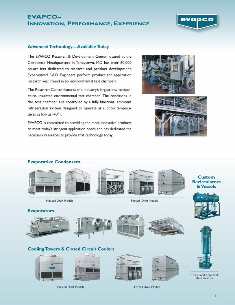
Advanced Technology—Available Today
The EVAPCO Research & Development Center, located at the
Corporate Headquarters in Taneytown, MD has over 60,000
square feet dedicated to research and product development.
Experienced R&D Engineers perform product and application
research year round in six environmental test chambers.
The Research Center features the industry’s largest low temper-
ature, insulated environmental test chamber. The conditions in
the test chamber are controlled by a fully functional ammonia
refrigeration system designed to operate at suction tempera-
tures as low as -40°F.
EVAPCO is committed to providing the most innovative products
to meet today’s stringent application needs and has dedicated the
necessary resources to provide that technology today.
Evaporative Condensers
Horizontal & VerticalRecirculators
CustomRecirculators
& Vessels
Induced Draft Models Forced Draft Models
Cooling Towers & Closed Circuit Coolers
Forced Draft ModelsInduced Draft Models
Evaporators

World Headquarters/Research and Development Center
EVAPCO Facilities
WReD
®
Visit EVAPCO’s Website at: http://www.evapco.com
EVAPCO–YOUR ONE SOURCEFOR QUALITY REFRIGERATION SYSTEM COMPONENTS.
4M/11-09/DGD
EVAPCO...SPECIALISTS IN HEAT TRANSFERPRODUCTS AND SERVICES.
EVAPCO, Inc. — World Headquarters & Research/Development Center
EVAPCO, Inc.World HeadquartersP.O. Box 1300Westminster, MD 21158 USAPhone: 410-756-2600Fax: 410-756-6450E-mail: [email protected]
EVAPCO Asia/Pacific
EVAPCO Asia/Pacific Headquarters1159 Luoning Rd. Baoshan Industrial ZoneShanghai, P. R. China, Postal Code: 200949Phone: (86) 21-6687-7786Fax: (86) 21-6687-7008E-mail: [email protected]
EVAPCO Europe
EVAPCO Europe, N.V.European HeadquartersIndustrieterrein Oost 40103700 Tongeren, BelgiumPhone: (32) 12-395029Fax: (32) 12-238527E-mail: [email protected]
EVAPCO East5151 Allendale LaneTaneytown, MD 21787 USAPhone: 410-756-2600Fax: 410-756-6450E-mail: [email protected]
EVAPCO Midwest1723 York RoadGreenup, IL 62428 USAPhone: 217-923-3431Fax: 217-923-3300E-mail: [email protected]
EVAPCO West1900 West Almond AvenueMadera, CA 93637 USAPhone: 559-673-2207Fax: 559-673-2378E-mail: [email protected]
EVAPCO Iowa925 Quality DriveLake View, IA 51450 USAPhone: 712-657-3223Fax: 712-657-3226
EVAPCO IowaSales & Engineering1234 Brady BoulevardOwatonna, MN 55060 USAPhone: 507-446-8005Fax: 507-446-8239E-mail: [email protected]
Refrigeration Valves & Systems CorporationA wholly owned subsidiary of EVAPCO, Inc.1520 Crosswind Dr.Bryan, TX 77808 USAPhone: 979-778-0095Fax: 979-778-0030E-mail: [email protected]
McCormack Coil Company, Inc.A wholly owned subsidiary of EVAPCO, Inc.P.O. Box 17276333 S.W. Lakeview BoulevardLake Oswego, OR 97035 USAPhone: 503-639-2137Fax: 503-639-1800E-mail: [email protected]
EvapTech, Inc.A wholly owned subsidiary of EVAPCO, Inc.8331 Nieman RoadLenexa, KS 66214 USAPhone: 913-322-5165Fax: 913-322-5166E-mail: [email protected]
Tower Components, Inc.A wholly owned subsidiary of EVAPCO, Inc.5960 US HWY 64ERamseur, NC 27316Phone: 336-824-2102Fax: 336-824-2190E-mail: [email protected]
EVAPCO Newton701 East Jourdan StreetNewton, IL 62448 USAPhone: 618-783-3433Fax: 618-783-3499E-mail: [email protected]
EVAPCO Europe, S.r.l.Via Ciro Menotti 10I-20017 Passirana di RhoMilan, ItalyPhone: (39) 02-939-9041Fax: (39) 02-935-00840E-mail: [email protected] Europe, S.r.l.Via Dosso 223020 Piateda Sondrio, ItalyEVAPCO Europe, GmbHBovert 22D-40670 Meerbusch, GermanyPhone: (49) 2159-69560Fax: (49) 2159-695611E-mail: [email protected] coil a/sA wholly owned subsidiary of EVAPCO, Inc.Knøsgårdvej 115DK-9440 Aabybro DenmarkPhone: (45) 9824 4999Fax: (45) 9824 4990E-mail: [email protected] S.A. (Pty.) Ltd.A licensed manufacturer of EVAPCO, Inc.18 Quality RoadIsando 1600Republic of South AfricaPhone: (27) 11-392-6630Fax: (27) 11-392-6615E-mail: [email protected] Engineering Industries Co.A licensed manufacturer of EVAPCO, Inc.5 Al Nasr Road St.Nasr City, Cairo, EgyptPhone: (20) 2-290-7483/(20) 2-291-3610Fax: (20) 2-404-4667/ (20) 2-290-0892E-mail: [email protected]
Evapco (Shanghai) Refrigeration Equipment Co., Ltd.1159 Louning Rd., Baoshan Industrial ZoneShanghai, P.R. China, Postal Code: 200949Phone: (86) 21-6687-7786Fax: (86) 21-6687-7008E-mail: [email protected]
Beijing EVAPCO Refrigeration Equipment Co., Ltd.Yan Qi Industrial Development DistrictHuai Rou County Beijing, P.R. China, Postal Code: 101407Phone: (86) 10 6166-7238Fax: (86) 10 6166-7395E-mail: [email protected]
Evapco Australia (Pty.) Ltd.34-42 Melbourne RoadP.O. Box 436Riverstone, N.S.W. Australia 2765Phone: (61) 2 9627-3322Fax: (61) 2 9627-1715E-mail: [email protected]
EvapTech Asia Pacific Sdn. BhdA wholly owned subsidiary of EvapTech, Inc.IOI Business Park, 2/F Unit 21Persiaran Puchong Jaya SelatanBandar Puchong Jaya,47170 Puchong, Selangor, MalaysiaPhone: (60-3) 8070 7255Fax: (60-3) 8070 5731E-mail: [email protected]
EVAPCO North America
EVAPCO, Inc. • P.O. Box 1300 • Westminster, MD 21158 USAPHONE: 410-756-2600 • FAX: 410-756-6450 • E-MAIL: [email protected]
Bulletin 802C
Top Related