


Languages
Pages
Legal

Aeroelasticity and Structural Dynamics Research Laboratory
Coupled Nonlinear Aeroelasticity and Flight Dynamics of Highly Flexible
AircraftWeihua Su
Assistant ProfessorDepartment of Aerospace Engineering and Mechanics
The University of AlabamaTuscaloosa, AL
Applied Modeling & Simulation Seminar Series NASA Ames Research Center
Moffett Field, CAAug. 27, 2014
Aeroelasticity and Structural Dynamics Research Laboratory
Overview
• Introduction– Background– Motivation
• Theoretical formulation– Geometrically nonlinear beam– Unsteady aerodynamics– Flight dynamic modeling
• Numerical studies• Concluding remarks• Ongoing and future developments
2
Aeroelasticity and Structural Dynamics Research Laboratory
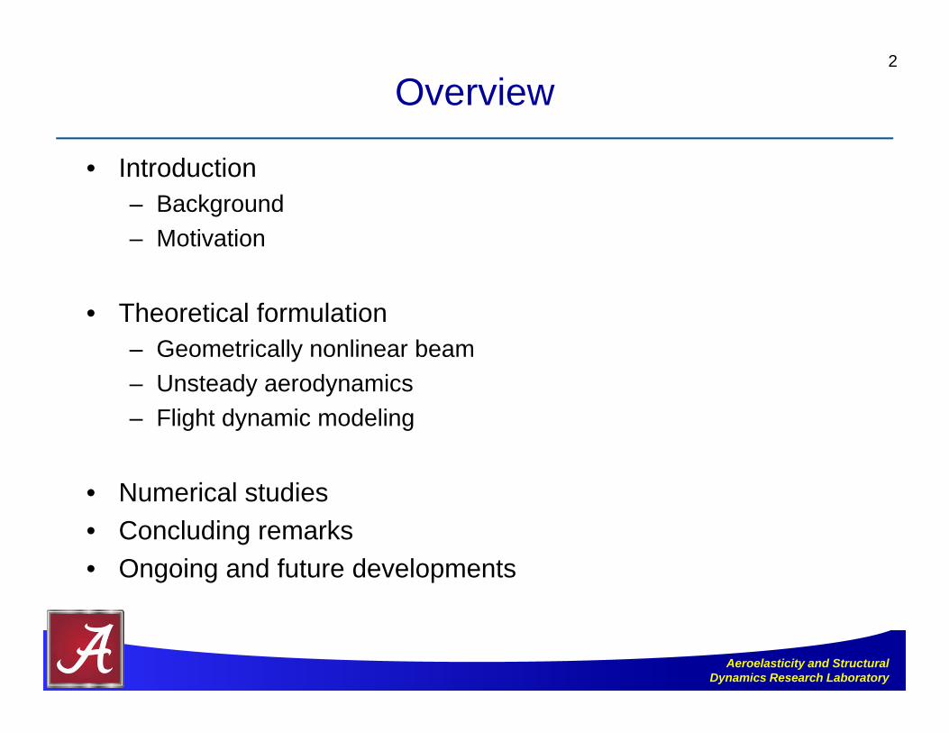
Aerodynamic Efficiency andWing Aspect-Ratio
3
F-22aAR = 2.36
ETA (Germany)AR = 51.33
B787-8AR = 11.08
0
1
or ln WLR ED W
Large wing aspect-ratio to achieve high aerodynamic efficiency
High aerodynamic efficiency
Aeroelasticity and Structural Dynamics Research Laboratory
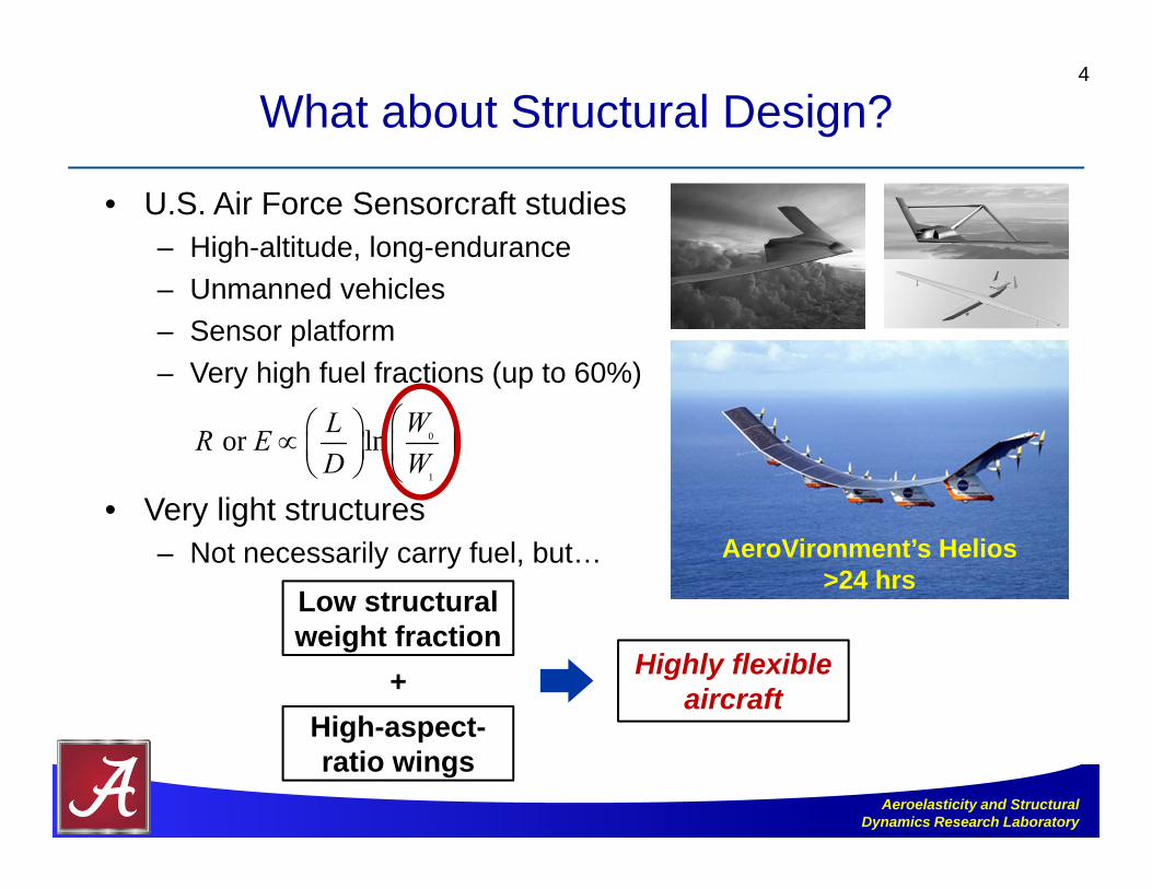
What about Structural Design?
• U.S. Air Force Sensorcraft studies– High-altitude, long-endurance– Unmanned vehicles– Sensor platform– Very high fuel fractions (up to 60%)
• Very light structures– Not necessarily carry fuel, but…
4
AeroVironment’s Helios>24 hrs
0
1
or ln WLR ED W
Highly flexible aircraft
Low structural weight fraction
High-aspect-ratio wings
+
Aeroelasticity and Structural Dynamics Research Laboratory
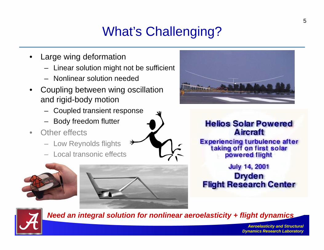
What’s Challenging?
• Large wing deformation– Linear solution might not be sufficient– Nonlinear solution needed
• Coupling between wing oscillation and rigid-body motion– Coupled transient response– Body freedom flutter
• Other effects– Low Reynolds flights– Local transonic effects
5
Need an integral solution for nonlinear aeroelasticity + flight dynamics

Aeroelasticity and Structural Dynamics Research Laboratory
Objectives
• Create a low-order aeroelastic and flight dynamic framework– Effectively represent dynamic behavior of highly flexible vehicle– Efficient solution– Facilitate active aeroelastic tailoring and control studies
• Explore structural, aerodynamic, and control techniques to enhance flight efficiency and performance– Reduce drag– Reduce power consumption– Suppress instability– Reject air disturbance
6
Aeroelasticity and Structural Dynamics Research Laboratory
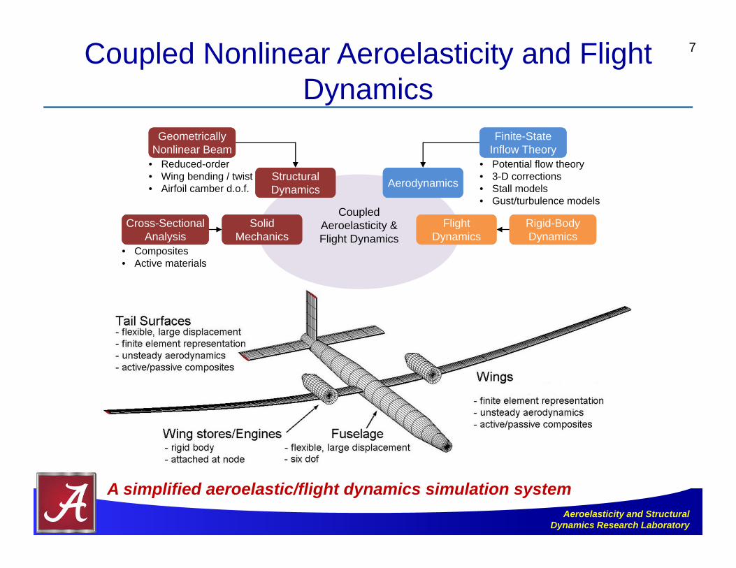
Coupled Nonlinear Aeroelasticity and Flight Dynamics
7
CoupledAeroelasticity &Flight Dynamics
• Reduced-order• Wing bending / twist • Airfoil camber d.o.f.
Geometrically Nonlinear BeamGeometrically
Nonlinear Beam
Structural DynamicsStructural Dynamics
• Composites • Active materials
Cross-Sectional Analysis
Cross-Sectional Analysis
Solid Mechanics
Solid Mechanics
• Potential flow theory• 3-D corrections• Stall models• Gust/turbulence models
Finite-State Inflow TheoryFinite-State
Inflow Theory
AerodynamicsAerodynamics
Rigid-Body DynamicsRigid-Body Dynamics
Flight Dynamics
Flight Dynamics
A simplified aeroelastic/flight dynamics simulation system
Aeroelasticity and Structural Dynamics Research Laboratory
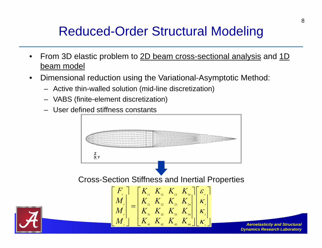
Reduced-Order Structural Modeling
• From 3D elastic problem to 2D beam cross-sectional analysis and 1D beam model
• Dimensional reduction using the Variational-Asymptotic Method:– Active thin-walled solution (mid-line discretization)– VABS (finite-element discretization)– User defined stiffness constants
8
X YZX YZ
11 12 13 14
21 22 23 24
31 32 33 34
41 42 43 44
x x
x x
y y
z z
F K K K KM K K K KM K K K K
K K K KM
Cross-Section Stiffness and Inertial Properties

Aeroelasticity and Structural Dynamics Research Laboratory
Basic Coordinate Systems
• Global frame (G)• Body frame (B) – origin not
necessary to be C.G. of vehicle• Body frame motion variables
• Local beam frame (w)• Auxiliary local frame (b)
9
B
B
B B
B B
B B
B B
pb
p vb
p vb

Aeroelasticity and Structural Dynamics Research Laboratory
Strained-Based Geometrically Nonlinear Beam Formulation
• Geometrically nonlinear beam formulation[1]
• Four local strain degrees-of-freedom (ε): extension, twist, flatwise bending, and chordwise bending
• Constant-strain elements• Capture large complex deformations with fewer
elements – computationally efficient• Isotropic and anisotropic constitutive relations
10
[1] Su, W., and Cesnik, C.E.S., “Strain-Based Geometrically Nonlinear Beam Formulation for Modeling Very Flexible Aircraft,” International Journal of Solids and Structures, Vol. 48, No. 16-17, 2011, pp. 2349-2360. (doi: 10.1016/j.ijsolstr.2011.04.012)
Sample element deformations with constant strain
Strains () and body velocities ()are independent variables
Aeroelasticity and Structural Dynamics Research Laboratory
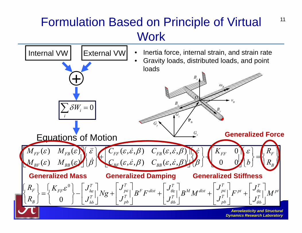
Formulation Based on Principle of Virtual Work
11
0
( ) ( ) ( , , ) ( , , ) 0( ) ( ) ( , , ) ( , , ) 0 0
0
FF FB FF FB FFF
BF BB BF BB B
TT TF p F disthFF
TTB pbhb
M M C C RKM M C C Rb
R JJ JKNg B F
R JJ
T TpM dist pt ptTT Tpbb b
J JB M F M
JJ J
0ii
W
Equations of Motion
Generalized Mass Generalized Damping Generalized Stiffness
Generalized Force
Internal VW External VW
+
• Inertia force, internal strain, and strain rate• Gravity loads, distributed loads, and point
loads
Aeroelasticity and Structural Dynamics Research Laboratory
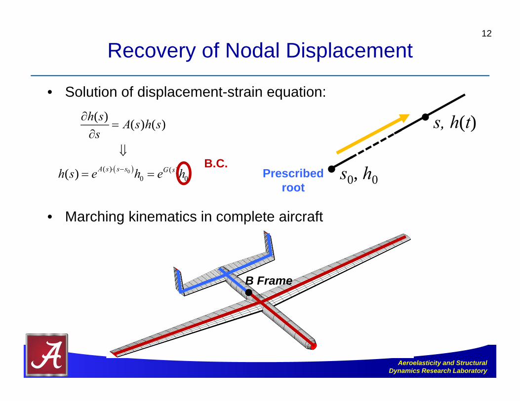
Recovery of Nodal Displacement
• Solution of displacement-strain equation:
• Marching kinematics in complete aircraft
12
0( ) ( )0 0
( ) ( ) ( )
( ) A s s s G s
h s A s h ss
h s e h e h
Prescribed root
s0, h0
s, h(t)
B Frame
B.C.
Aeroelasticity and Structural Dynamics Research Laboratory
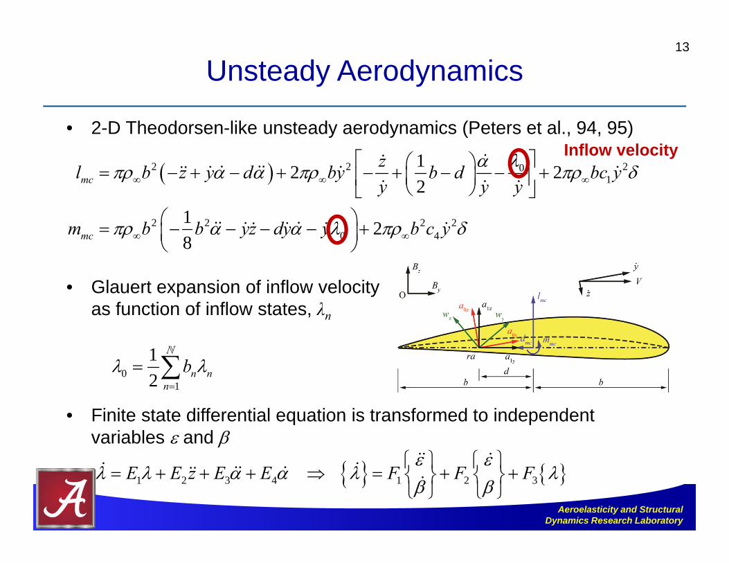
Unsteady Aerodynamics
• 2-D Theodorsen-like unsteady aerodynamics (Peters et al., 94, 95)
• Glauert expansion of inflow velocityas function of inflow states, λn
• Finite state differential equation is transformed to independent variables and
13
2 2 201
2 2 2 20 4
12 22
1 28
mc
mc
zl b z y d by b d bc yy y y
m b b yz dy y b c y
Inflow velocity
01
12 n n
n
b
1 2 3 4 1 2 3E E z E E F F F
Aeroelasticity and Structural Dynamics Research Laboratory
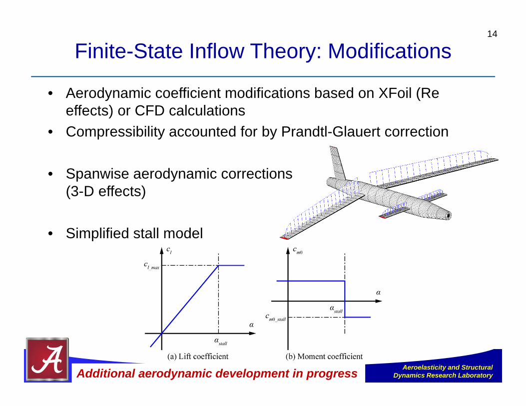
Finite-State Inflow Theory: Modifications
• Aerodynamic coefficient modifications based on XFoil (Re effects) or CFD calculations
• Compressibility accounted for by Prandtl-Glauert correction
• Spanwise aerodynamic corrections(3-D effects)
• Simplified stall model
14
Additional aerodynamic development in progress
Aeroelasticity and Structural Dynamics Research Laboratory
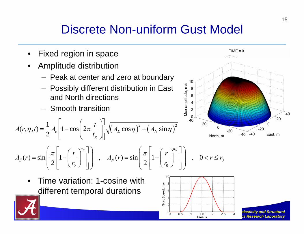
• Fixed region in space• Amplitude distribution
– Peak at center and zero at boundary– Possibly different distribution in East
and North directions– Smooth transition
• Time variation: 1-cosine withdifferent temporal durations
Discrete Non-uniform Gust Model15
2 21( , , ) 1 cos 2 cos sin2 c E N
g
tA r t A A At
00 0
( ) sin 1 , ( ) sin 1 , 02 2
E Nn n
E Nr rA r A r r rr r
Aeroelasticity and Structural Dynamics Research Laboratory
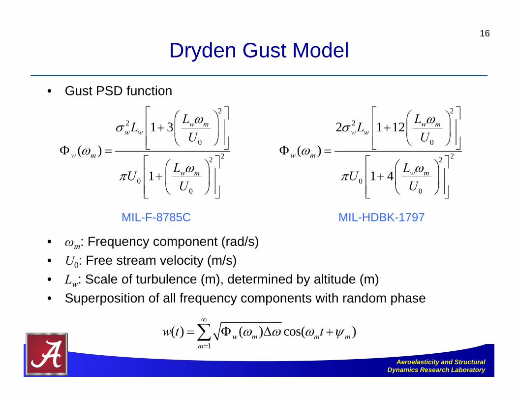
Dryden Gust Model
• Gust PSD function
• ωm: Frequency component (rad/s)• U0: Free stream velocity (m/s)• Lw: Scale of turbulence (m), determined by altitude (m)• Superposition of all frequency components with random phase
16
22
0
22
00
1 3
( )
1
w mw w
w m
w m
LLU
LUU
22
0
22
00
2 1 12
( )
1 4
w mw w
w m
w m
LLU
LUU
1
( ) ( ) cos( )w m m mm
w t t
MIL-F-8785C MIL-HDBK-1797

Aeroelasticity and Structural Dynamics Research Laboratory
PSD and Time History of Gust Velocity
• Frequency band [0.1~6] Hz• adjusted to obtain enough
wing deformation• Uniform spanwise distribution
17
w
Power concentrated at the lowfrequency range
Aeroelasticity and Structural Dynamics Research Laboratory
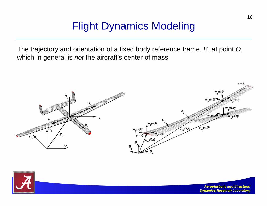
Flight Dynamics Modeling18
The trajectory and orientation of a fixed body reference frame, B, at point O, which in general is not the aircraft’s center of mass

Aeroelasticity and Structural Dynamics Research Laboratory
Full Air Vehicle Model for Flight Simulations
• Elastic equations of motion
• Finite-state 2-D unsteady aerodynamics
• Body reference frame propagation
19
( ) ( ) ( )M C , , K R , , , , , , ,ub
1 2 3F F F
Strains (4 by m structural d.o.f.)
Body velocities (6 flight dynamic d.o.f.)
Inflow states (N by m aerodynamic d.o.f.)
Control inputs
12
0GBBP C
Inertial velocities (6 d.o.f.)
Frame orientation(4 quaternions)

Aeroelasticity and Structural Dynamics Research Laboratory
Numerical Studies
20
Aeroelasticity and Structural Dynamics Research Laboratory
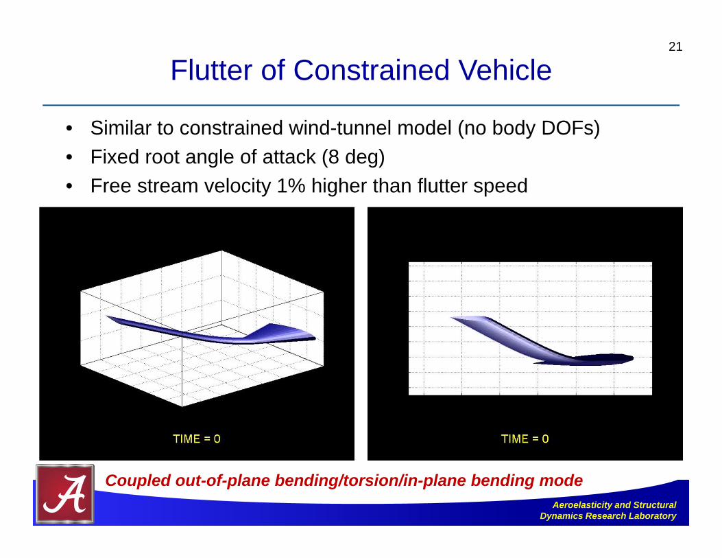
Flutter of Constrained Vehicle
• Similar to constrained wind-tunnel model (no body DOFs)• Fixed root angle of attack (8 deg)• Free stream velocity 1% higher than flutter speed
21
Coupled out-of-plane bending/torsion/in-plane bending mode

Aeroelasticity and Structural Dynamics Research Laboratory
Blended-Wing-Body (BWB) Model
• Properties inspired from HiLDA (High Lift over Drag Active Wing) wind-tunnel model
22
Elevon: 25% chord

Aeroelasticity and Structural Dynamics Research Laboratory
Comparison of Flutter Modes with Rigid-Body Constraints
23
All cases trimmed for 6,096 m (20,000 ft) altitude, same fuel condition
Fully constrained rigid-body DOFs
Additional plunge DOF
With pitch and plunge DOFs (“same” for free flight – 6 DOFs)
Flutter Speed Frequency
Fully constrained
dof’s172.52 m/s 7.30 Hz
+ plunging 164.17 m/s 7.07 Hz
+ pitching and plunging 123.17 m/s 3.32 Hz
Free flight 123.20 m/s 3.32 Hz
Traditional wind-tunnel setup maybe non-conservative – need rigid-body DOFs in the aeroelasticanalyses, simulations, and tests

Aeroelasticity and Structural Dynamics Research Laboratory
Highly Flexible Flying Wing Model
• Representative of Helios prototype[2]
– Five engines and three pods– Payloads applied at center pod– Empty gross mass: 726 kg
24
[2] Patil, M.J., and Hodges, D.H., “Flight Dynamics of Highly Flexible Flying Wings,” Journal of Aircraft, Vol. 43, No. 6, 2006, pp. 1790-1798.

Aeroelasticity and Structural Dynamics Research Laboratory
Trim Results and Flight Stability
• Speed: 12.2 m/s at sea level; Payload: 0 – 227 kg (at center pod)• Linearization about each trimmed condition with increase of payloads• Root locus for phugoid mode (left: flexible, right: rigid) • Unstable phugoid mode for payload > 152 kg
25
Payload
[2]
Flexible Rigid
Payload
Zero payload: span-loaded
Full payload: center-loaded
Nonlinear aeroelastic/flight dynamic characteristics dependent on trim conditions
Aeroelasticity and Structural Dynamics Research Laboratory
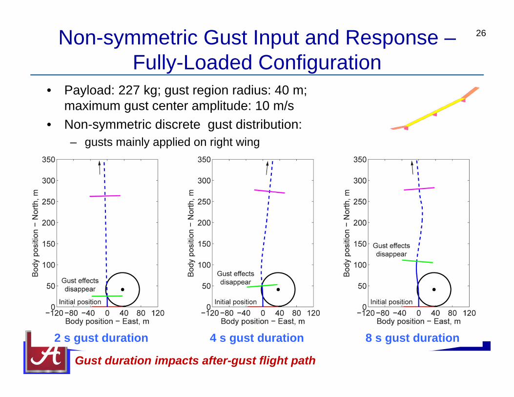
Non-symmetric Gust Input and Response –Fully-Loaded Configuration
• Payload: 227 kg; gust region radius: 40 m;maximum gust center amplitude: 10 m/s
• Non-symmetric discrete gust distribution:– gusts mainly applied on right wing
26
2 s gust duration 4 s gust duration 8 s gust duration
Gust duration impacts after-gust flight path

Aeroelasticity and Structural Dynamics Research Laboratory
Instantaneous Vehicle Positions and Orientations
• Positions and orientations at 0, 5, 12, 18, 24, and 30 s, respectively
27
Flight Direction
8-s gust4-s gust
2-s gust
Illustration of unstable Phugoid mode

Aeroelasticity and Structural Dynamics Research Laboratory
Animation of Vehicle Motion with Gust Perturbations
28
2-s gust4-s gust8-s gust
Aeroelasticity and Structural Dynamics Research Laboratory
Concluding Remarks
• Framework for modeling and analyzing highly flexible aircraft– Coupled nonlinear aeroelastic/flight dynamic simulation– Strain-based geometrically-nonlinear beam– Incompressible unsteady aerodynamics (with compressibility corrections
and stall models)– Rigid-body flight dynamics
• Highly flexible aircraft have radically different behavior than conventional aircraft– Coupling between aircraft deformation and rigid-body motions changes
flutter boundaries– Flutter boundary in free flight condition may be different from constrained
flight– Finite amplitude gust can excite instabilities
29

Aeroelasticity and Structural Dynamics Research Laboratory
Concluding Remarks (Cont’d)
• What did we learn from the physics of highly flexible aircraft?– Operating (trim) condition should be the basis in weight, structural,
and stability analyses• Deformed geometry other than the undeformed shape
– Traditional linear solution to highly flexible aircraft aeroelasticity might not be sufficient
• Nonlinear solution is required– Coupling between aeroelasticity and flight dynamics needs to be
considered• Aeroelastic models should incorporate the rigid-body motion, and vice
versa• Individual solutions might not be appropriate
30

Aeroelasticity and Structural Dynamics Research Laboratory
Active Aeroelastic Tailoring and Control
• Traditional approach for aerodynamic/flight control
• Drag due to control surfaces• Conformal wing shape changes
– Integral strain actuation of bending/twist
31
NASA Langley MFC Actuator
Aeroelasticity and Structural Dynamics Research Laboratory
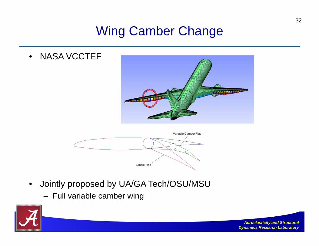
Wing Camber Change
• NASA VCCTEF
• Jointly proposed by UA/GA Tech/OSU/MSU– Full variable camber wing
32
Aeroelasticity and Structural Dynamics Research Laboratory
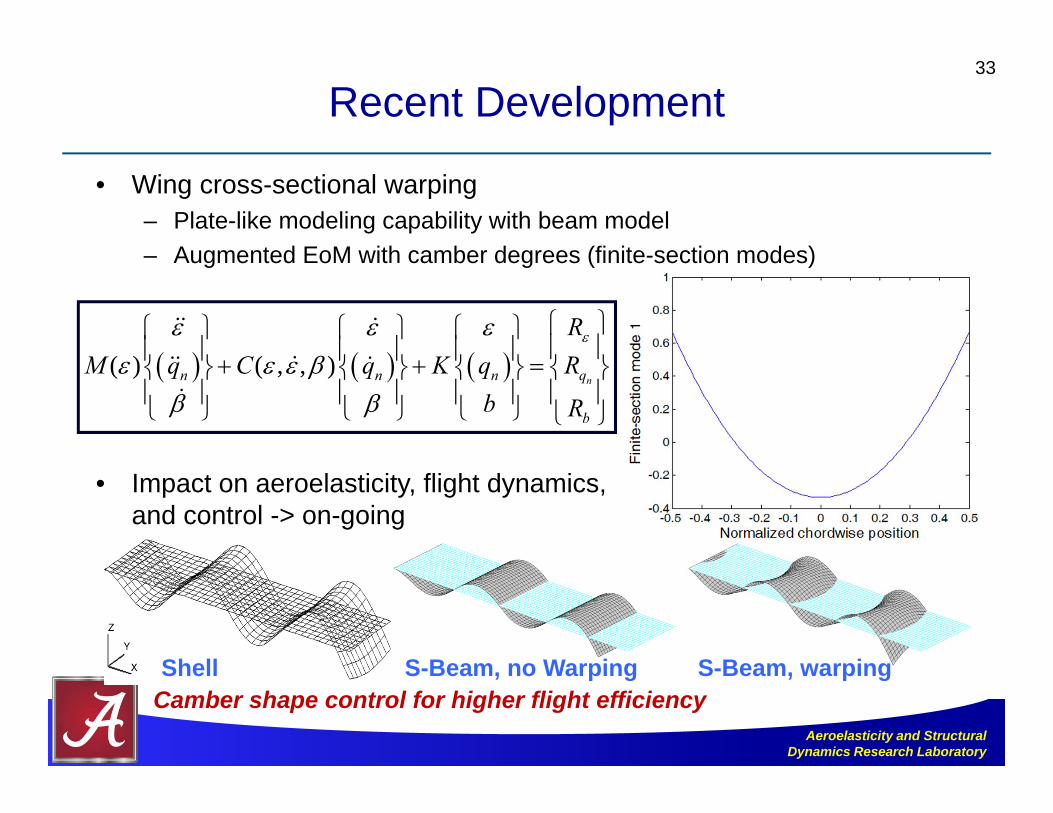
Recent Development
• Wing cross-sectional warping– Plate-like modeling capability with beam model– Augmented EoM with camber degrees (finite-section modes)
• Impact on aeroelasticity, flight dynamics,and control -> on-going
33
Shell S-Beam, no Warping S-Beam, warping
( ) ( , , )nn n n q
b
RM q C q K q R
b R
Camber shape control for higher flight efficiency
Aeroelasticity and Structural Dynamics Research Laboratory
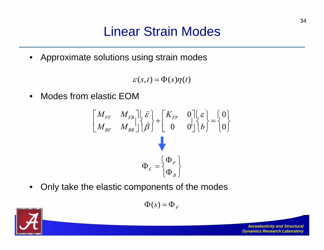
Linear Strain Modes
• Approximate solutions using strain modes
• Modes from elastic EOM
• Only take the elastic components of the modes
34
( , ) ( ) ( )s t s t
0 00 0 0
FF FB FF
BF BB
M M KM M b
FC
B
( ) Fs

Aeroelasticity and Structural Dynamics Research Laboratory
Modal Equations35
1 2 3
FF FB FF FB FF F
BF BB BF BB B
M M C C K R
M M C C R
F F F
1 1 2 2 3
( , , , , )
( , , , , )FF FB FF FB FF F
BF BB BF BB B
F B F B
M M C C K R
M M C C R
F F F F F

Aeroelasticity and Structural Dynamics Research Laboratory
Highly Flexible Wing
• Beam properties:
• Nonlinear flutter speed: 23 m/s
36
Ref. 3* Current (linear) Current (nonlinear)
Velocity (m/s) 32.2 32.2 23.3Frequency (Hz) 3.60 3.60 1.61
[3] Patil, M.J., Hodges, D.H. and Cesnik, C.E.S., “Nonlinear Aeroelasticity and Flight Dynamics of High-Altitude Long-Endurance Aircraft,” Journal of Aircraft, Vol. 38, No. 1, 2001, pp. 88-94.
Length (m) 16Chord (m) 1Mass per length (kg/m) 0.75x-sectional c.g. position 50% chord x-sectional shear center 50% chord Rotational inertia (kg·m) 0.1Flat bending rigidity (N·m2) 2.00 × 10⁴
Edge bending rigidity (N·m2) 4.00 × 10⁴
Torsional rigidity (N·m2) 1.00 × 10⁴

Aeroelasticity and Structural Dynamics Research Laboratory
Modal-Based Static Solution
• Convergence of static solutions with different number of modes
• For more discussion:
37
Modes about undeformed shape Modes about deformed shape
2% error
0.5% error 0.5% error
Fewer modes required if modes are obtained about deformed shape
[4] Su, W., and Cesnik, C.E.S., “Strain-Based Analysis for Geometrically Nonlinear Beams: a Modal Approach,” Journal of Aircraft, Vol. 51, No. 3, 2014, pp. 890–903. (doi: 10.2514/1.C032477)
Aeroelasticity and Structural Dynamics Research Laboratory
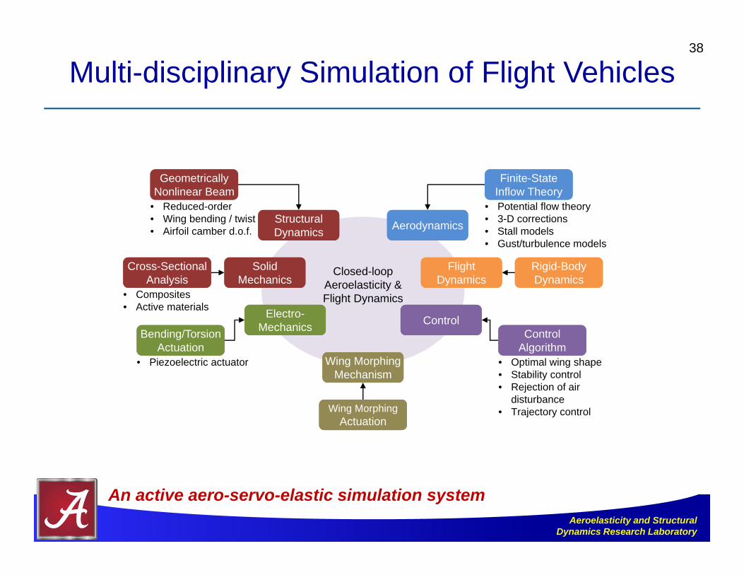
Multi-disciplinary Simulation of Flight Vehicles38
Closed-loopAeroelasticity &Flight Dynamics
• Reduced-order• Wing bending / twist • Airfoil camber d.o.f.
Geometrically Nonlinear BeamGeometrically
Nonlinear Beam
Structural DynamicsStructural Dynamics
• Piezoelectric actuator
Bending/Torsion Actuation
Bending/Torsion Actuation
Electro-Mechanics
Electro-Mechanics
• Composites• Active materials
Cross-Sectional Analysis
Cross-Sectional Analysis
Solid Mechanics
Solid Mechanics
• Optimal wing shape• Stability control• Rejection of air
disturbance• Trajectory control
Control AlgorithmControl
Algorithm
ControlControl
• Potential flow theory• 3-D corrections• Stall models• Gust/turbulence models
Finite-State Inflow TheoryFinite-State
Inflow Theory
AerodynamicsAerodynamics
Rigid-Body DynamicsRigid-Body Dynamics
Flight Dynamics
Flight Dynamics
Wing Morphing Mechanism
Wing Morphing Mechanism
Wing MorphingActuation
Wing MorphingActuation
An active aero-servo-elastic simulation system
Aeroelasticity and Structural Dynamics Research Laboratory
39
Top Related