


Languages
Pages
Legal

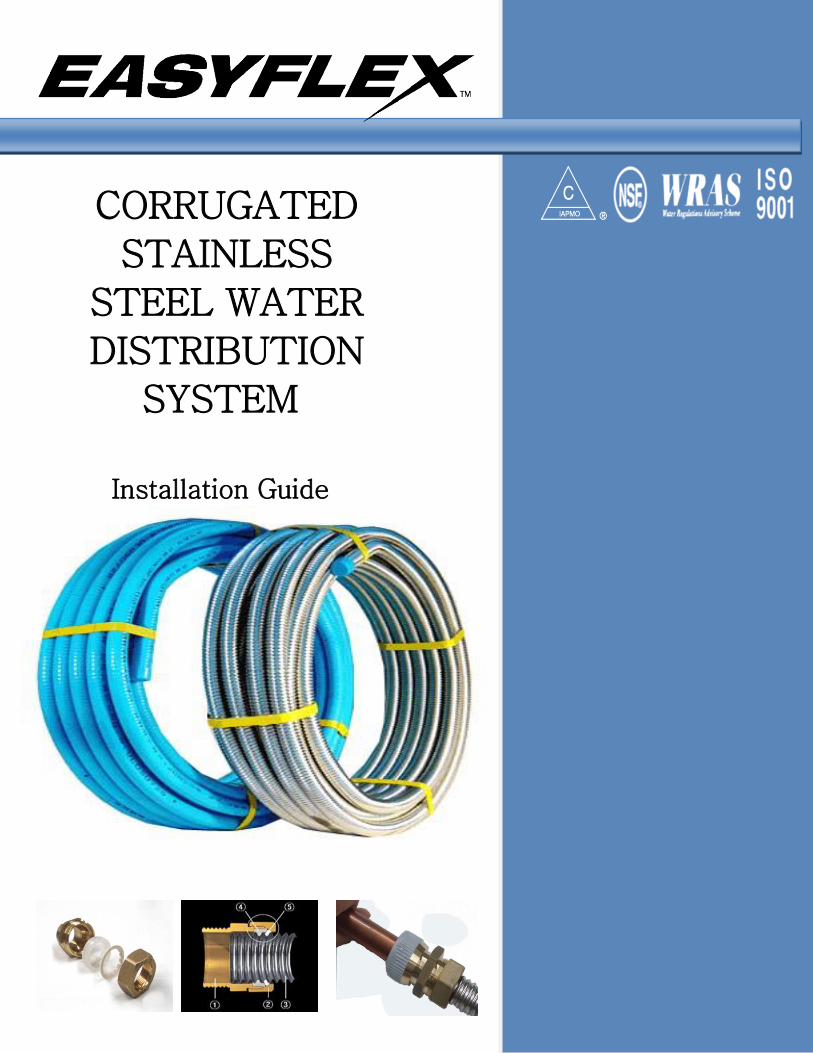
CORRUGATED
STAINLESS
STEEL WATER
DISTRIBUTION
SYSTEM
Installation Guide

EASYFLEX Page 2 www.easyflexusa.com
Table of Table of Contents
Disclaimer 3
Product Description 4 Specifications 4
Installation 5-11
Bending 5 Supporting/Hanging 5
Cutting 5-6 Stripping Coating 6
Installing Fittings 6 Tightening 7
Trouble Shooting Connection 7
Tubing Location 7-8 Branch Location 8
Bored Holes 8 Mounting Through Metal 9
Outdoor/Underground Installations 9-10
Grounding/Bonding 10 Manifold Installation 10
Repair and Replacement 11 Testing Installation 11
Friction Loss 12
Pipe Sizing 13 Warranty 14-15
Contact Information 16

EASYFLEX Page 3 www.easyflexusa.com
Installation of Flexible Tubing
Disclaimer
All installations must comply with applicable standards, practices and codes set by local building authority. Manufacturer’s suggested instructions do not supersede applicable local standards, practices or codes. Please contact the manufacturer or local building authority for any questions on installation. Only qualified, licensed professionals or qualified professionals under supervision of a licensed professional should install, modify or repair plumbing pipe and fixtures. Precautions must be taken to ensure that any exposed flexible piping is not damaged or abused during construction or assembly. All systems should be stored in secure, dry location prior to installation. Only fittings provided by the manufacturer are to be used. Ends of tubing are to be temporarily capped and plugged prior to installation to prevent entrance of dirt or other debris. Contact with sharp objects or harmful substances are to be avoided. Contact with any chemicals containing chlorides or ammonia must be followed by thorough rinse and wipe dry.

EASYFLEX Page 4 www.easyflexusa.com
Product Description
The Water Line System is a flexible water distribution system for potable, hot-cold water in
residential and commercial applications. The tubing can also be used for glycol based and distilled
water distribution. Made from corrosion resistant 304 or (on special order) 316L annealed stainless
steel, the water line features durability and
flexibility enabling numerous bends and twisting of the tubing for installation, use and repair. The
tubing features brass fittings with sealing gaskets that allow for simple installation and enhanced
corrosion resistance and strength. In addition to the
regular brass fittings of tees, reducers and sockets, is the Push-Fit fitting. This tool-free, push-on
connection allows flexible tubing to be connected with rigid pipe like copper, galvanized steel or CPVC.
The tubing features operating pressure above 147 psi and operating temperature of 212°F. The
stainless steel tubing comes in rolls from 50’ to over
150’ and diameters from 1/2” to 2”. The flexible tubing can be purchased with red or blue
polyethylene coating, which makes installation and repair easier with color coding and adds additional
protection to the tubing from harsh chemicals or
environmental conditions.
The Use of EASYFLEX is not restricted by the style, size, age, type of construction, height, or physical
layout of the building. It can withstand vibrations,
movement, seismic forces, shearing and mechanical structural strain. Corrugated stainless pipe helps to
prevent ruptures in the plumbing system by flexing and absorbing vibrations and stresses.
Product Ratings, Capabilities and Material
Specifications
Material Specification
Tube: 0.012 in. thick 304 Annealed
Stainless Steel (ASTM A 240)
Fittings: Nut & Body – Brass UNS
C37700 (ASTM DS-561) Isolating Ring – Nylon 66
Sealing Ring – Dow Corning K760
Silicon
Teeth ring – 304 Stainless Steel (ASTM
A 240) 0.02 in. thick Polyethylene coating
(ASTM D 3350)
Push-Fit nut: Nylon 66
Features & Availability
IAPMO/UPC IGC 233 and ANSI/NSF 61 tested and approved
Manufacturer’s recommended Working Pressure: 220psi (1/2”), 176psi (3/4”), 147psi (1”)
IAPMO Tested Operating Temp &
Pressure : 212°F, 147psi
Diameter: 1/2”,3/4”, 1”,1-1/4”
Length: 50 ft, 100 ft, 150 ft / roll (Available in special lengths)
Uncoated or Blue/Red PE (Polyethylene)
Velocity: 8fps
Product Standards and Listings EASYFLEX Water Line tube and fittings are
produced to the requirements of IAPMO IGC 233-2006, ASTM A 240, ASME B1.20.1, ASTM D 3350,
ASTM DS-561 and ANSI/NSF 61 – 2005, section 4. Standard Title
ANSI/NSF Standard 61 Drinking Water
System Components – Health Effects
ASTM A 240 Specification for Chromium and
Chromium-Nickel Stainless Steel Plate, Sheet, and Strip for Pressure Vessels and for General
Applications
ASTM D 335 Specifications for Polyethylene Plastics Pipe and Fittings Materials
ASME B1.20.1 Pipe Threads, General Purpose
ASTM DS-561 Metals and Alloys in the Unified
Numbering System
IAPMO IGC 233 1. Material
2. Performance 3. Marking and Identification
Applications: New Construction Mechanical Plumbing
Retrofit Solar Water Heating Repair Tankless Water Heaters
Laboratories Hot Water Distribution
Commercial Manufacturing

EASYFLEX Page 5 www.easyflexusa.com
USER WARNING! Please Read Disclaimer before installing.
Tools For Installation
1. Open End Wrench – For Assembly of Fittings
2. Adjustable Wrench – For manifold Body 3. Pipe Wrench – For attachments of tubing to
fittings and manifold body. 4. Drill – For boring clearance holes through wood
or metal framing. Recommended clearance hole size: 1/2” larger than tubing diameter.
5. Utility knife with sharp blade
6. Tubing Cutter 7. Pliers
Flexible Tubing Installation Practices
General Installation EASYFLEX flexible water piping can be used to
provide outdoor connections to appliances that are attached to, or in close proximity to the
building. EASYFLEX flexible water piping can be routed in
most locations where traditional water piping
materials are installed: inside hollow wall cavities, along or through floor joists in basements, on
top of the joists in attics, on roof tops or along soffits or in chases outside of buildings.
For underground burial, the flexible water tubing
can be laid directly in the ground. The fittings must be encased in a sleeve of PVC or other
insulator. Tubing and fittings must be encased in a PVC sleeve when run through concrete.
Flexible water tubing can be used in conjunction
with any rigid pipe in either new construction or renovation and replacement piping installations.
Use gradual or low degree bends to maximize water flow and reduce friction loss.
Bending The Tubing
Bending flexible water piping is one feature
which contributes to the speed of installation. Tubing can be bent to desired position without
restriction on bending radius. Multiple tight bends can restrict the water flow and increase
pressure drop. Care must be taken to avoid
repeated sharp bending, stretching, kinking or twisting of tubing. Gradual bends are suggested
whenever possible.
Horizontal Runs and Supporting All horizontal runs shall be supported as
specified in chart below. Tubing that runs parallel to the joists should be
supported to the center of the vertical face at
least 3” from the floor or ceiling. Tubing that runs perpendicular to the joists
should be supported, preferably routed through drilled holes in the joists or inside an I-beam
flange.
Table 2. Horizontal and Inclined Runs
Tube
Size
(inch)
Spacing
of
Supports
1/2 6 ft
3/4 8 ft
1 8 ft
1 1/4 8 ft
Vertical Runs and Support
The spacing between supports on vertical runs shall not exceed 10 feet.
The tubing shall be supported in a workman like
manner with piping straps, tubing clips, bands, brackets or hangers suitable for the size and
weight of the tubing.
Tubing edges are sharp. Take care
when handling cut tubing.
Cutting Tubing to Length Determine the proper length of the tubing. Use a
standard tubing cutter equipped with a sharp
(preferably hardened steel) cutting wheel. Whenever possible, cut a straight section of tubing
that hasn’t been bent. It is not necessary to remove polyethylene jacket prior to cutting. A pipe cutter
can cut through the polyethylene tubing jacket. The cut must be centered in a convolution (valley)
between two corrugations. Use full, circular cutting
stroke continuing in the same directions as starting
EASYFLEX Page 6 www.easyflexusa.com
in. When the wheel has cut through jacket and is in
contact with the stainless steel, it is important to slightly tighten the cutting wheel. A quarter turn is
all that is necessary. You will hear the stainless steel “pop” or “crack” when you begin to cut
through. Do not over tighten cutter. The tubing
may flatten out if the cutter is tightened too much, and the cut edges will be deformed. Continue
cutting until the tube is cut all the way around or only a small edge is attached. If necessary, bend,
but, don’t twist cut edge to separate tubing, then, ensure the twisted edge is not deformed or it will
obstruct flow. Remove burs or rough edges with
pliers if necessary.
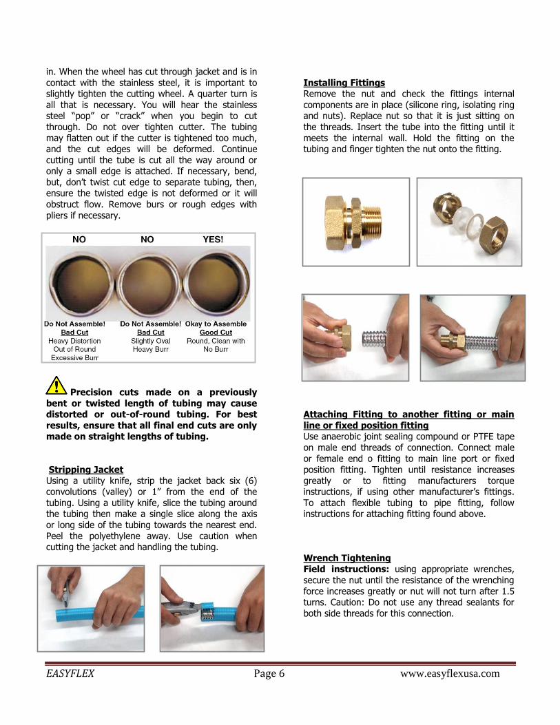
Precision cuts made on a previously
bent or twisted length of tubing may cause distorted or out-of-round tubing. For best
results, ensure that all final end cuts are only made on straight lengths of tubing.
Stripping Jacket
Using a utility knife, strip the jacket back six (6) convolutions (valley) or 1” from the end of the
tubing. Using a utility knife, slice the tubing around the tubing then make a single slice along the axis
or long side of the tubing towards the nearest end.
Peel the polyethylene away. Use caution when cutting the jacket and handling the tubing.
Installing Fittings Remove the nut and check the fittings internal
components are in place (silicone ring, isolating ring and nuts). Replace nut so that it is just sitting on
the threads. Insert the tube into the fitting until it
meets the internal wall. Hold the fitting on the tubing and finger tighten the nut onto the fitting.
Attaching Fitting to another fitting or main
line or fixed position fitting Use anaerobic joint sealing compound or PTFE tape
on male end threads of connection. Connect male
or female end o fitting to main line port or fixed position fitting. Tighten until resistance increases
greatly or to fitting manufacturers torque instructions, if using other manufacturer’s fittings.
To attach flexible tubing to pipe fitting, follow instructions for attaching fitting found above.
Wrench Tightening Field instructions: using appropriate wrenches,
secure the nut until the resistance of the wrenching
force increases greatly or nut will not turn after 1.5 turns. Caution: Do not use any thread sealants for
both side threads for this connection.
EASYFLEX Page 7 www.easyflexusa.com
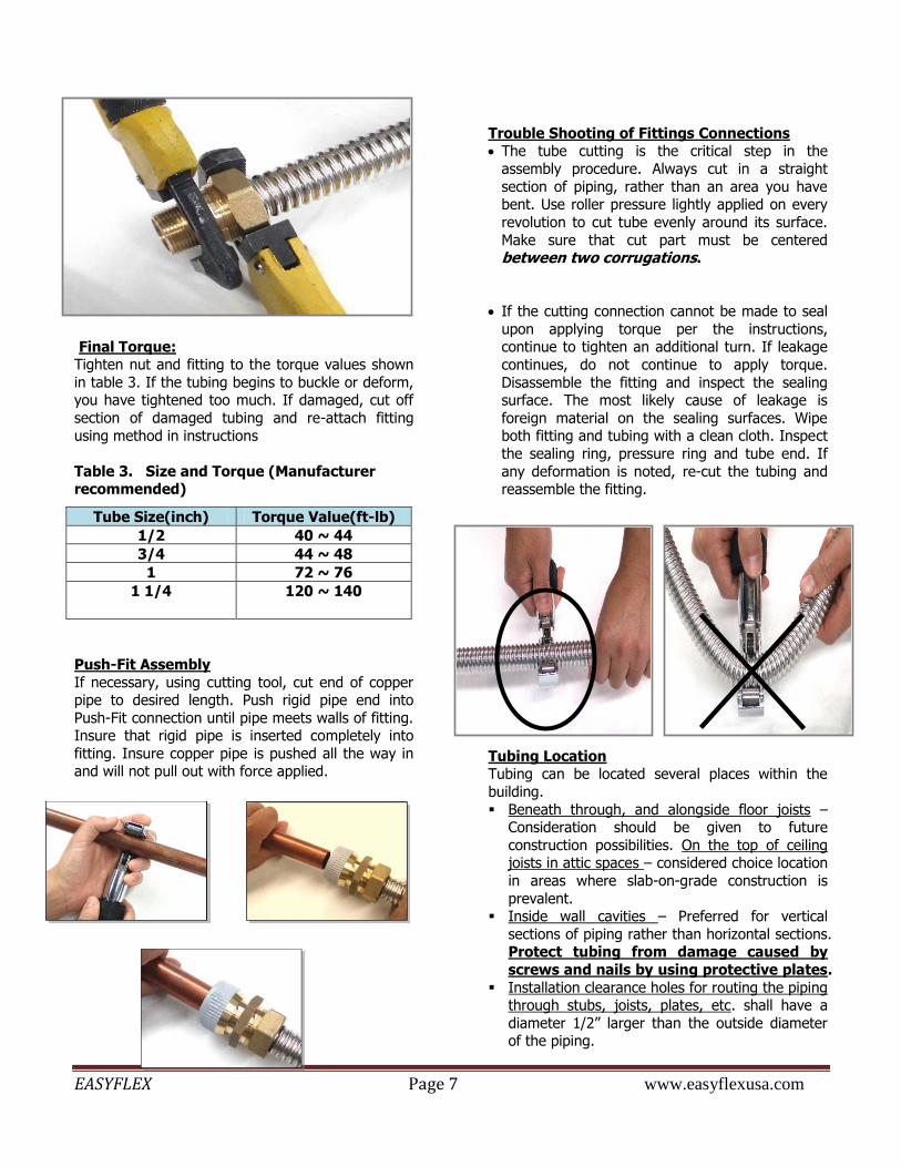
Final Torque: Tighten nut and fitting to the torque values shown
in table 3. If the tubing begins to buckle or deform, you have tightened too much. If damaged, cut off
section of damaged tubing and re-attach fitting
using method in instructions
Table 3. Size and Torque (Manufacturer recommended)
Push-Fit Assembly
If necessary, using cutting tool, cut end of copper pipe to desired length. Push rigid pipe end into
Push-Fit connection until pipe meets walls of fitting. Insure that rigid pipe is inserted completely into
fitting. Insure copper pipe is pushed all the way in and will not pull out with force applied.
Trouble Shooting of Fittings Connections The tube cutting is the critical step in the
assembly procedure. Always cut in a straight
section of piping, rather than an area you have bent. Use roller pressure lightly applied on every
revolution to cut tube evenly around its surface.
Make sure that cut part must be centered between two corrugations.
If the cutting connection cannot be made to seal
upon applying torque per the instructions, continue to tighten an additional turn. If leakage
continues, do not continue to apply torque.
Disassemble the fitting and inspect the sealing surface. The most likely cause of leakage is
foreign material on the sealing surfaces. Wipe both fitting and tubing with a clean cloth. Inspect
the sealing ring, pressure ring and tube end. If
any deformation is noted, re-cut the tubing and reassemble the fitting.
Tubing Location Tubing can be located several places within the
building.
Beneath through, and alongside floor joists – Consideration should be given to future
construction possibilities. On the top of ceiling joists in attic spaces – considered choice location
in areas where slab-on-grade construction is
prevalent. Inside wall cavities – Preferred for vertical
sections of piping rather than horizontal sections. Protect tubing from damage caused by
screws and nails by using protective plates.
Installation clearance holes for routing the piping through stubs, joists, plates, etc. shall have a
diameter 1/2” larger than the outside diameter of the piping.
Tube Size(inch) Torque Value(ft-lb)
1/2 40 ~ 44
3/4 44 ~ 48
1 72 ~ 76
1 1/4 120 ~ 140

EASYFLEX Page 8 www.easyflexusa.com
Branching Avoid branching if not necessary. This minimizes
the number of joints in the system. Utilize only manufacturer supplied fittings and support
tubing and fittings as described in previous
instructions.
Bored Holes In locations where flexible water tubing is
installed through bored holes in joists, rafters, or wood members, holes shall be bored so that the
edge of the hole is not less than 2” from the
nearest edge of the wood member. The diameter of the bored holes shall be a minimum
of 1/2” larger than the outside diameter of the tubing jacket unless the hole size conflicts with
local building codes, which shall prevail.
Where holes are to be bored in load bearing vertical members of the wall framing, the size of
such holes shall not be larger than 40% of the width of the member. Holes up to 60% of the
member’s width are permitted if the members are doubled. No more than two successive
double bored members are permitted
Use a pipe grommet to secure the tubing through a bored hole.
Table 4 Installation Clearance Holes
Tubing Size Drill Hole Size
1/2” 1 3/8”
3/4” 1 5/8”
1” 1 7/8”
1-1/4” 2 1/8”

EASYFLEX Page 9 www.easyflexusa.com
Water Line Mounted Through Metal Framing The installation instructions for metal framed
structures are same as wood framed structure with the following exception.
When flexible water tubing passes through
metal members it shall be protected by one of the following methods:
1. Busing securely fastened in the opening of the metal member.
2. Grommets securely fastened in the opening of the metal member.
The installer shall insure that no physical contact
occurs between the metal member and the flexible water tubing.
Metal Studs
For installations involving horizontal runs through galvanized steel stubs, the use of
plastic grommets supplied by the stud manufacturer is recommended. The use of
these grommets will reduce the likelihood of damage to the tubing non-metallic jacket.
Underground Installations
General Provisions Inspection: Before installation, flexible water
tubing should be thoroughly inspected for cuts,
scratches, gouges or split ends which might have occurred to the products during shipping
and handling. Do not use damaged sections. Damaged sections found must be cut-out and
discarded.
Where local codes conflict with this manual, local codes take precedence.
Flexible water piping can be buried directly in the ground, but not fittings, and not directly
embedded in concrete without a sleeve (e.g. patio slabs, foundations and walkways). When
burial is required, insure trench and backfill do
not contain corrosive elements. EASYFLEX flexible water piping can be routed inside
nonmetallic (e.g. PVC or PE) conduit, which conforms to standards to prevent freezing in
exterior installations. Field wrappings shall
provide equivalent protection for fittings. Nonmetallic (e.g. PVC or PE) conduit may also
be used to protect fittings and shall be sealed at any exposed end to prevent water from
entering.
Water service pipe and the building sewer or
drainage pipe shall be separated by a minimum of 5 feet of undisturbed or compacted earth.
Exceptions to this standard are applied as per compliance with local codes.
Potable water service and distribution pipe shall
not be located in, under or above cesspools, septic tanks, septic tank drainage fields or
seepage pits. When installed along the side of a structure in
an exposed condition. The flexible water piping must be protected inside a conduit or installed
in a location which will not subjected it to
crushing or puncture damage.
Trench Preparation: Trench bottom shall be
solid with no hollows, lumps, rocks, or other materials that could damaged the tubing. All
piping shall be installed at least 12” inches below the average frost depth. In case of
loose, rocky soil, the trench should be excavated
at least 6” deeper than the desired pipe depth and filled with suitable soils. Regardless of soil
condition, the backfill should be free of rocks, glass, or other sharp objects.
Laying the tubing: Tubing should be laid with
sufficient slack (snaking) to accommodate any
contraction or elongation prior to backfilling. Minimum bending radius requirements for
flexible water tubing shall be followed. In poor soil conditions, it’s necessary to excavate deeper
and use good clean fill or granular fill to smooth
the trench bottom.
Backfilling: Do not use clay, silt, or rocky backfill. Remove the construction materials or
foreign objects from trench prior to backfilling. The tubing and fittings should be surrounded
EASYFLEX flexible water tubing must
only be installed by qualified licensed
professionals or under supervision of a licensed
professional. All installations must comply with
local code requirements and the instructions
contained in the EASYFLEX Installation Guide

EASYFLEX Page 10 www.easyflexusa.com
with good clean fill, or sand. Compact the initial
backfill around the tubing to provide adequate tubing support and prevent settlement. It is
particularly important to adequately compact the soil around the tap connection.
Electrical Grounding/Bonding The EASYFLEX flexible water piping and/ or the
components must not be used as a grounding electrode of any part of an electrical system.
*Grounding Tubing Proper bonding and grounding may reduce
the risk of damage in a lightning strike.
A lighting strike can cause the system to become energized, and if not bonded, the
differences in potential can cause the charge to arc to another system. This
arcing can cause damage to the system.
The CSST shall be bonded in accordance with NFPA 70-2005, section 250.104, using
a bonding clamp approved for steel pipe to provide an adequate bonding connection
which is continuous. A bonding connector shall be installed to the tubing near the
service connection end and not connected
to the brass nut of the fitting, in accordance with NEC section 250.70, and
shall be permanently connected to the grounding electrode system. The bonding
conductor shall be a 6 AWG copper wire,
connected to either the electrical service enclosure, the grounded conductor at the
electrical service, the grounding electrode conductor or to one or more of the
grounding electrodes used.
Short lengths of tubing connected to a grounded appliance are acceptable.
Manifold Installations
Installation of Water Distribution Manifold Assembly
Manifolds are installed where multiple tubing
runs are made from a common location in a parallel arrangement. Depending on the location
and available space, different mounting arrangements are permitted. A manifold
assembly may be mounted on the surface of an
interior wall, between open floor joints, in attic spaces, or within a partition wall inside
ventilated enclosures the manifold assembly shall be installed in an accessible location where
it can be inspected, maintained and serviced if repair or replacement is required.
Horizontal Manifold Installation
Position the manifolds in the desired location and
nail and screw the mounting bracket to the studs. Make sure all valve handles have room for
operation.
Vertical Manifold Installation
Manifolds may be coupled end to end and installed vertically along a stud. Position the manifold in the
desired location and fasten it to the studs. Note: A vertical manifold installation usually
requires bending the flexible water tubing
immediately off the manifold. Extra care must be taken to assure that tube is not bent
in a radius smaller than the minimum permitted for flexible water pipe. Also make
sure that bending stress is not applied to the fitting that connects the tube to the manifold.
Selecting the Manifold Size EASYFLEX manifolds are designed for easy
connection to 1/2”, 3/4”, 1” flexible water line. When selecting the tube size, the following factors
should be considered:
1. Local code requirements 2. Water demand of the fixture
3. Distance from the manifold to the fixture 4. Elevation change from manifold to the fixture
5. Water pressure available to the manifold

EASYFLEX Page 11 www.easyflexusa.com
Repair and Replacement
Repair of Damaged Tubing Damaged tubing runs shall be repaired in
accordance with this design guide and installation instruction manual. The repair can
result in a line splice which may be located in a
concealed location. If the tubing is damaged refer to the following subsections to determine
the severity of damaged and, if necessary, the method of repair.
Classification of Repairs No repairs or replacement of the tubing is
necessary if the tubing is only slightly
dented by crushing. EASYFLEX flexible water piping must be
repaired or replaced under the following circumstances.
− The tubing has been significantly damaged
− The tubing has been punctured.
− The tubing has been bent beyond it’s minimum bend radius so that a crease
or kink appears
Method of Repair
The installer shall determine the most reliable and economical method of repair
using one of the following methods: Replace the entire tubing run: In most
cases when the tubing run is short and easily
accessible, it can be replaced faster and more economically than repairing the damaged section.
This is the preferred method because extra fittings are not required.
Repair the damaged section: The damaged tubing can be repaired by each of two methods
described below:
1. Remove the section of tubing which is damaged and reconnect the new ends with
a single mechanical coupling. 2. Remove the section of tubing which is
damaged and splice in a new section of
tubing with two mechanical couplings. Use this repair method if the extent of the
damage covers more than a small area, and there is not enough slack in the
existing tubing run to make-up the damaged length.
Testing Installation
After all connections in the line have been
made and tightened, test water line by running water through the line at the same
pressure for intended use. If leaks are found,
see trouble shooting instructions.
15042 Parkway Loop, Unit D Tustin, CA 92780-6522
www,easyflexusa.com
15042 Parkway Loop, Unit D Tustin, CA 92780-6522
www,easyflexusa.com

EASYFLEX Page 12 www.easyflexusa.com
Friction Loss Friction loss of tubing calculated in pounds per square inch (PSI) of pressure lost per foot of tubing with a friction
constant = 70 and no bends. Sharp bends are calculated the same as for fittings and gradual bends calculated the same as straight pipe.
GPM NOMINAL SIZE (ID)
1/2" 3/4" 1" 1-1/4"
1 0.032 0.004 0.002 0.001
2 0.114 0.015 0.005 0.002
3 0.241 0.032 0.012 0.004
4 0.410 0.055 0.020 0.008
5 0.619 0.083 0.030 0.011
6 0.867 0.117 0.042 0.016
7 1.153 0.156 0.055 0.021
8 1.476 0.199 0.071 0.027
9 1.836 0.248 0.088 0.034
10 2.231 0.301 0.107 0.041
Note:
1. Table is based on the *Hazen-Williams formula. 2. Fluid velocities in excess of 5-8 ft/sec are not recommended. 3. Friction loss values shown are for the flow rates that do not exceed a velocity of 8 ft/sec.
*P = 4.52Q1.85
C1.85
d4.87
Where: P = friction loss, psi per linear foot Q = flow, gpm D = average, I.D., in inches C = 70, friction constant

EASYFLEX Page 13 www.easyflexusa.com
Pipe Sizing
Pipe shall be sized in reference to the supplied table included in this installation guide and or in compliance with
local codes and standards. The water distribution system shall be designed, and pipe sizes shall be selected such
that under conditions of peak demand, the capacities at the fixture supply pipe outlets shall not be less than required for the combined fixture demand.
For specific information on fixture demand, see local building code.
Pipe Sizing Chart Developed Length in Feet
Pressure Range: 30-45 psi
Diameter Size (in) 40 60 80 100 150 200 250 300 400
1/2 6 5 4 3 2 1 1 1 1
3/4 16 16 13 11 8 5 5 4 4
1 28 24 22 21 16 14 12 11 10
1-1/4 35 33 30 27 23 22 21 18 17
Pressure Range: 46-60 psi Diameter
Size (in) 40 60 80 100 150 200 250 300 400
1/2 7 7 6 5 4 3 2 2 1
3/4 20 20 19 16 13 10 8 7 6
1 38 37 35 32 27 22 20 18 16
1-1/4 38 38 38 38 38 38 33 31 26
Pressure Range: over 60 psi Diameter
Size (in) 40 60 80 100 150 200 250 300 400
1/2 7 7 7 6 5 4 3 3 2
3/4 19 19 19 19 16 12 10 9 7
1 38 38 38 38 34 29 26 23 20
1-1/4 38 38 38 38 38 38 38 38 33
Values in Water Supply fixture Units (WSFU)
Source: IAPMO IGC-233-2008

EASYFLEX Page 14 www.easyflexusa.com
WARRANTY
EASYFLEX LIMITED WARRANTY EASYFLEX FLEXIBLE TUBING FOR WATER,
FITTINGS AND MANIFOLDS
Subject to the conditions and limitations in this Limited Warranty, EASYFLEX warrants to the real
owner as installed by licensed plumbers, who
purchase and properly install in a hot and cold potable water distribution system its Water Line
System corrugated stainless steel tubing (CSST), fittings and manifold plumbing system, sold by
EASYFLEX, under normal conditions of use, will be free from failure caused by manufacturing defect,
from the time of installation:
(I) Corrugated stainless steel tubing for a
period of fifty (50) years. (II) Brass fittings and stainless steel manifolds
for a period of twenty five (25) years.
Under this warranty, you only have a right to
reimbursement if the failure or leak resulted from a manufacturing defect in the products covered by
this warranty and occurred during the warranty
period. You do not have a remedy or right of reimbursement under this warranty and this
warranty does not apply if the failure or any resulting damage is caused by (1) components in
the plumbing system other than those
manufactured or sold by EASYFLEX; (2) not designing, installing, inspecting or testing the
system in accordance with EASYFLEX’S installation instructions at the time of the installation,
applicable code requirements, and good plumbing
practices; (3) improper handling and protection of the product prior to or during installation,
inadequate freeze protection, exposure to water pressures or temperatures in excess of the
limitations on the pipe or tubing, or application of unauthorized solvents or chemicals.; (4) acts of
nature such as earthquakes, fire, flood, or
landslide; (5) damage caused by lightning without proper grounding as per NFPA 780, NEC 2005
article 250.70 and clamps complying with UL 467 standards; (6) remain in its originally installed
location; (7) show no evidence of tampering,
mishandling, neglect, accidental damage, modification or repair without the approval of
EASYFLEX; (8) exposure to abnormal environmental
conditions relative to the norm for the installation
site and outside manufacturer specified pressure and temperature range; including chemical and
biological substance exposure; (9) freezing during or after the installation or inadequate freeze
protection; (10) exposure to operating use and or
conditions outside those specified by manufacturer.
In the event of a leak or other failure in the system, it is the responsibility of the property owner to
obtain and pay for the repairs. Only if the warranty applies will EASYFLEX be responsible for
reimbursement under this warranty. The part or
parts which you claim failed should be kept and EASYFLEX contacted by writing to the address
below or telephoning 714.258.2600 within thirty (30) days after the leak or other failure and
identifying yourself as having a warranty claim. You
should be prepared to ship, at your expense, the product which you claim failed due to a
manufacturing defect, document the date of installation, and the amount of any claimed bills
which you wish reimbursed. Within a reasonable time after notification, EASYFLEX will investigate
the reasons for the failure, which includes the right
to inspect the product at EASYFLEX and reasonable access to the site of the damage in order to
determine whether the warranty applies. EASYFLEX will notify you in writing of the results of its review.
In the event that EASYFLEX determines that the failure or leak and any resulting damages were the
result of a manufacturing defect in the products covered by this warranty, EASYFLEX will reimburse
the property owner for reasonable repair or
replacement charges to include drywall and painting or plastering costs, as well as damages to
personal property resulting from the failure or leak. EASYFLEX SHALL NOT BE LIABLE FOR
CONSEQUENTIAL ECONOMIC LOSS DAMAGES
UNDER ANY LEGAL THEORY AND WHETHER ASSERTED BY DIRECT ACTION, FOR
CONTRIBUTION OR INDEMNITY OR OTHERWISE. THE ABOVE LIMITED WARRANTY
IS IN LIEU OF ALL OTHER WARRANTIES, EXPRESS OR IMPLIED, INCLUDING BUT NOT
LIMITED TO, THE IMPLIED WARRANTIES OF
MERCHANTABILITY AND FITNESS FOR A PARTICULAR PURPOSE.
Other than this limited warranty, EASYFLEX does not authorize any person or firm to create for it any
other obligation or liability in connection with its
products. Licensed plumbers are authorized to

EASYFLEX Page 15 www.easyflexusa.com
provide this warranty in connection with any
warranty extended by them to builders or owners of site built construction.
Some states do not allow the exclusion or limitation
of incidental or consequential damages in certain
types of transactions, so the above exclusion or limitations may not apply to you. This limited
warranty gives you specific legal right and you also may have other rights which vary from state to
state.
EASYFLEX
15042 Parkway Loop #D Tustin, CA 92868
714-258-2600

EASYFLEX Page 16 www.easyflexusa.com
15042 Parkway Loop Unit D Tustin, CA 92780
PHONE: 888/577/8999 714/258/2600 888/577/8999
FAX: 714/258/2602 WEBSITE: www.easyflexusa.com
Top Related