


Languages
Pages
Legal

8/12/2019 COOPERATIVE MULTI-AGENTS DETECTION WITH SPATIALLY DISTRIBUTED ARRAY SENSORS
http://slidepdf.com/reader/full/cooperative-multi-agents-detection-with-spatially-distributed-array-sensors 1/7
8/12/2019 COOPERATIVE MULTI-AGENTS DETECTION WITH SPATIALLY DISTRIBUTED ARRAY SENSORS
http://slidepdf.com/reader/full/cooperative-multi-agents-detection-with-spatially-distributed-array-sensors 2/7
395
stage of environment signals and
sources parameters detection. In this
case, the estimation and detection is
used to acquire information on several
signals to make a selection decision.
The purpose of this work is to create a
complete multiagents system able to
detect environmental sources and listen
to them simultaneously. In our case,
multi-agents systems are presented as
new paradigm used to design
intelligent independent systems. To
accomplish this specific task, several
agents with different goals, must
cooperate on the system. In this paper
we are using arbitrary 3D architecturearray sensors combined with multi-
agents systems. By this approach we
are implementing cooperating agents
for detection and beamforming.
2 ARRAY SENSORS MODELING
Array sensors are formed with multiple
elementary sensors, each one with a
geometrical position in space and
considered as independent observer inrespect to a well-defined origin as
shown in Figure 1 [1-7]. Each sensor
provides a measure, if the array is
composed with “N” sensors then theoverall answer of the array will be
writes in vectorial form by (1) [2,7]:Figure 1. Array sensors general disposition
[2,5-7].
)(
)(
)(
)( 2
1
t x
t x
t x
t X
N
(1)
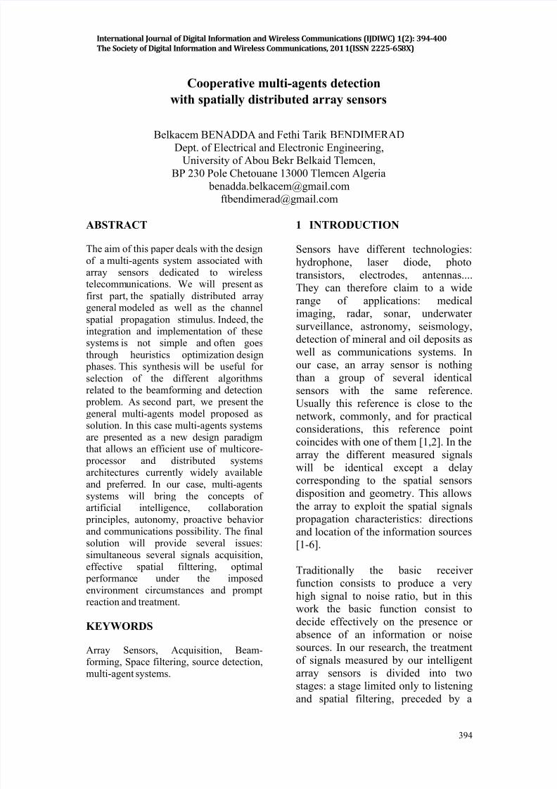
2.1 Propagation channel modeling
The propagation channel is defined as
the medium used by the different
signals between transmitters and
receivers [1,2,6-10]. Ideal connection
is achieved if the received signal is
exclusively the same as the emitted
one without distortion. Alas, in realitythe channel will alter the signals by
adding: noise, attenuation, fading,
absorption, dispersion, refraction,
reflection, Faraday rotation, glitter,
Dependence of polarization, Doppler
Effect, and multipath (see Figure 2)
[1,13,14].
Figure 2. The channel: fading, absorption,
dispersion, refraction, reflection and multipath,
effects.
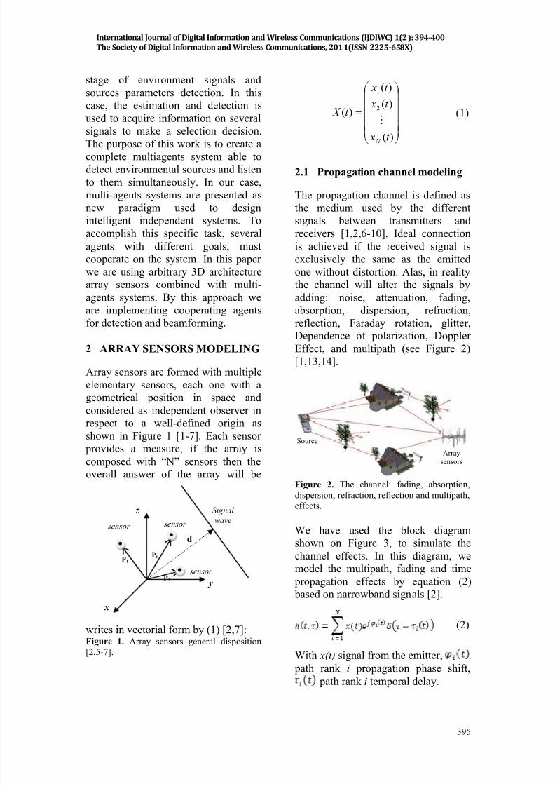
We have used the block diagram
shown on Figure 3, to simulate the
channel effects. In this diagram, we
model the multipath, fading and time
propagation effects by equation (2)
based on narrowband signals [2].
(2)
With x(t) signal from the emitter,
path rank i propagation phase shift,
path rank i temporal delay.
x
y
z Signal
wave
d
PiP1
P2
sensor sensor
sensor
Source
Arraysensors
International Journal of Digital Information and Wireless Communications (IJDIWC) 1(2): 394-400
The Society of Digital Information and Wireless Communications, 2011(ISSN 2225-658X)
8/12/2019 COOPERATIVE MULTI-AGENTS DETECTION WITH SPATIALLY DISTRIBUTED ARRAY SENSORS
http://slidepdf.com/reader/full/cooperative-multi-agents-detection-with-spatially-distributed-array-sensors 3/7
396
Figure 3. Implementation synoptic for
channel: multipath, fading, propagation delays
and noise effects.
2.2 Array sensors signals
specifications
The array response, detailed byequation (3), is a linear composition of
the noise B(t) and S i(t) the incident
signals on the array sensors.
L
i it S t X
1)()( (3)
Obviously, based on the channel
model, the number of incident signals
“ L” is greater than the source number[2,6].
For any signal S i(t), the various sensors
outputs are identical except a certain
delay which corresponds to the wave
propagation time [2,6]:
)(
)(
)(
)( 2
1
M i
i
i
i
t s
t s
t s
t S
(4)
with “ M ” the array sensors number.
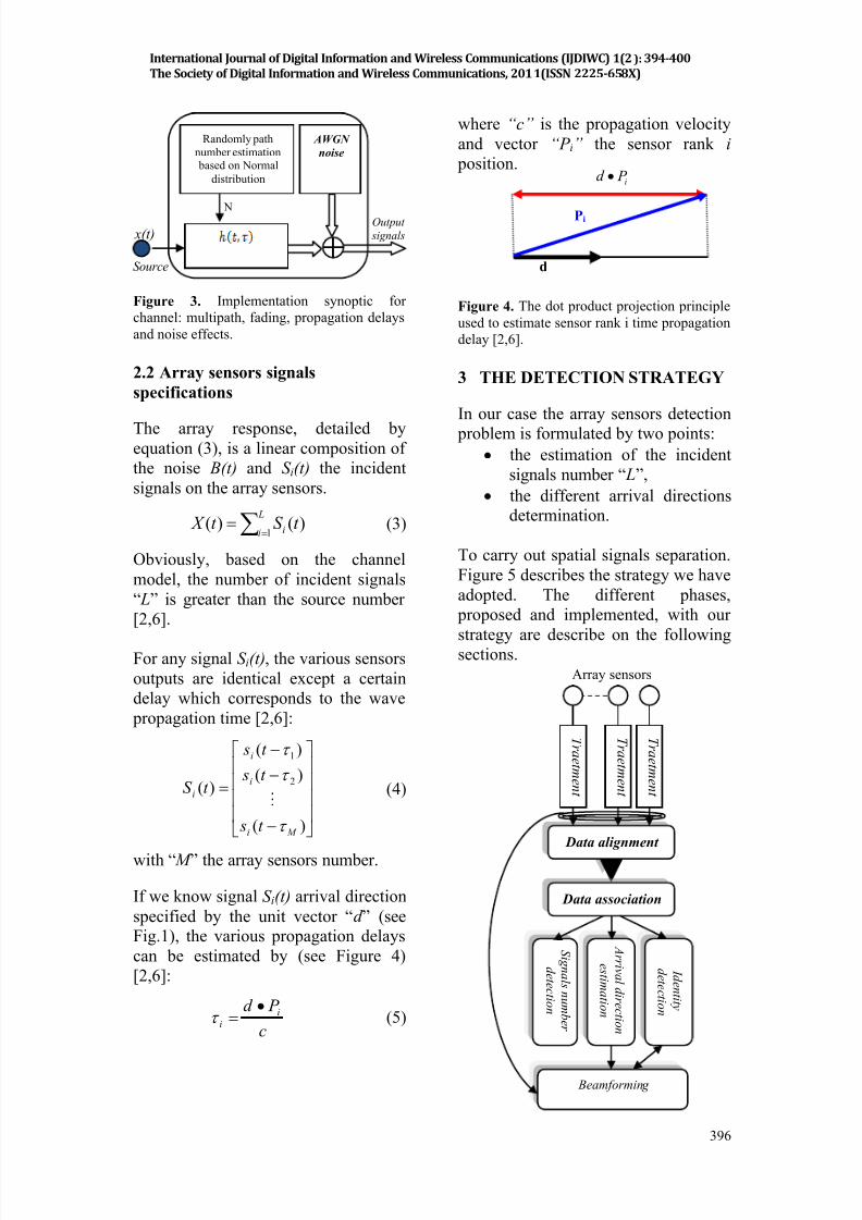
If we know signal S i(t) arrival direction
specified by the unit vector “d ” (seeFig.1), the various propagation delays
can be estimated by (see Figure 4)
[2,6]:
c
P d i
i
(5)
where “c” is the propagation velocity
and vector “P i” the sensor rank i
position.
Figure 4. The dot product projection principle
used to estimate sensor rank i time propagation
delay [2,6].
3 THE DETECTION STRATEGY
In our case the array sensors detection
problem is formulated by two points:
the estimation of the incident
signals number “ L”,
the different arrival directionsdetermination.
To carry out spatial signals separation.
Figure 5 describes the strategy we have
adopted. The different phases,
proposed and implemented, with our
strategy are describe on the followingsections.
Randomly path
number estimation based on Normal
distribution
AWGN
noise
N
x(t)
Source
Output
signals
Pi
d
i P d
S i g n a l s n u m b er
d e t e c t i o n
Beamforming
I d e n t i t y
d e t e c t i o n
Data alignment
Array sensors
T r a e t m e n t
T r a e t m e n t
T r a e t m e n t
Data association
A r r i v a l d i r e c t i o n
e s t i m a t i o n
International Journal of Digital Information and Wireless Communications (IJDIWC) 1(2): 394-400
The Society of Digital Information and Wireless Communications, 2011(ISSN 2225-658X)
8/12/2019 COOPERATIVE MULTI-AGENTS DETECTION WITH SPATIALLY DISTRIBUTED ARRAY SENSORS
http://slidepdf.com/reader/full/cooperative-multi-agents-detection-with-spatially-distributed-array-sensors 4/7
397
Figure 5. The different phases adopted on the
detection spatial filtering strategy.
3.1 Treatment and data alignment
phases
In this work we have considered only
narrow band signals; the treatment
phase will implement a passband filter.
However, the alignment phase will
perform an amplitude normalization to
cope with the channel attenuation
phenomena. Practically this is done
through emitted power control [11,12].
3.2 Data association phase
In this phase we will regroup the
measures from different “M” sensorsin a single entity. According to
equations (4) and (5) we can write:
L
i ii S t st X 1
)()( (6)
where S i denote the array space vector.
With narrow band assumption, the
array space vector expressed byequation:
e
ee
M j
j
j
iS
2
1
(7)
with propagation phase
delay. The matrix notation of the array
response can be written by:
T L t st st s At X 21.)( (8)
where “ A” denote the array manifoldmatrix (9):
LS S S A 21 (9)
It is now possible to calculate the
correlation matrix “ R” associated withthe measures from the two last phases
by (10), which can be expressed with
the manifold matrix by the equation(11).
H t X t X E R . (10)
GWN
H R AS A R ..
(11)
where “ RGWN ” the noise correlationmatrix. This matrix is diagonal
expressed by equation (12).
(12)
In this case represent the noise
variance, considered the same as the
noise power.
The association phase will estimate the
correlation matrix “ R” from the
different sensors outputs and in a
limited observation time “k ”. The
estimated matrix is carried out by
[11,12]:
(13)
For important “k” values, the matrix
“Ȓ” is considered as a good
approximation.
3.3 Detection and beamforming
phases
The detection phase based on the
preceding ones, is divided onto three
parts [2]:
Incident signals number detection,
Detection of signals arrival
directions,
Identity detection, this part is
introduced to correct the multipath
effect by removing redundant
signals,
The various sensors responses within
the network must be combined by a
suitable processing method in order to
spatially extract the signals on the
different detected directions [2].
Indeed, the detection result, speciallythe detected incident directions, will be
International Journal of Digital Information and Wireless Communications (IJDIWC) 1(2): 394-400
The Society of Digital Information and Wireless Communications, 2011(ISSN 2225-658X)
8/12/2019 COOPERATIVE MULTI-AGENTS DETECTION WITH SPATIALLY DISTRIBUTED ARRAY SENSORS
http://slidepdf.com/reader/full/cooperative-multi-agents-detection-with-spatially-distributed-array-sensors 5/7
398
used to implement spatial filtering
approach based on a geometrical Smith
algorithm or quadratic error
optimization [2,7]. The beamforming
phase, after acquisition and
demodulation, cooperate with the
identity detection to remove redundant
signals or improve the acquisition
quality.
4 MULTIAGENTS
IMPLEMENTATION
Multiagents systems with the
characteristics of artificial intelligence,
collaborations, proactivity, autonomy,and data exchange capabilities, provide
us, an interesting opportunity to
implement the above strategy. The
major problem encountered concern
the roles to be played by the different
agents in order to meet the overall
detection and simultaneous acquisition
objectives. The proposed architecture
exploits the logic, reactive and BDI
multi-agents architectures [2,16]. The
intelligence and roles played by thedifferent agents as well as predominant
behavior of our multi-agents system,
implementing the strategy of figure 5,
are shown on Figure 6, with an
indication of the main conversations
exchanged.
Figure 6. Predominant behavior proposed forour multi-agents system.
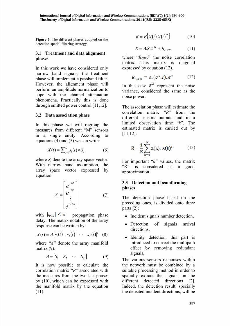
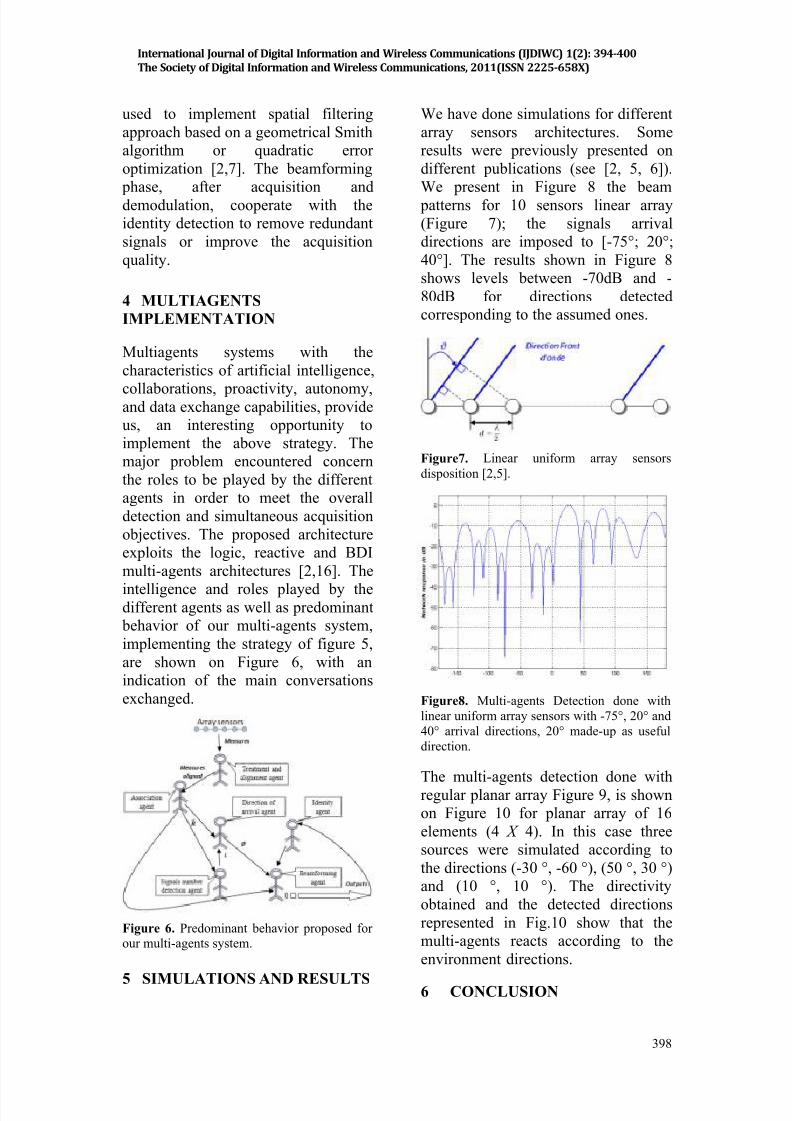
5 SIMULATIONS AND RESULTS
We have done simulations for different
array sensors architectures. Some
results were previously presented on
different publications (see [2, 5, 6]).
We present in Figure 8 the beam
patterns for 10 sensors linear array
(Figure 7); the signals arrival
directions are imposed to [-75°; 20°;
40°]. The results shown in Figure 8
shows levels between -70dB and -
80dB for directions detected
corresponding to the assumed ones.
Figure7. Linear uniform array sensors
disposition [2,5].
Figure8. Multi-agents Detection done with
linear uniform array sensors with -75°, 20° and
40° arrival directions, 20° made-up as useful
direction.
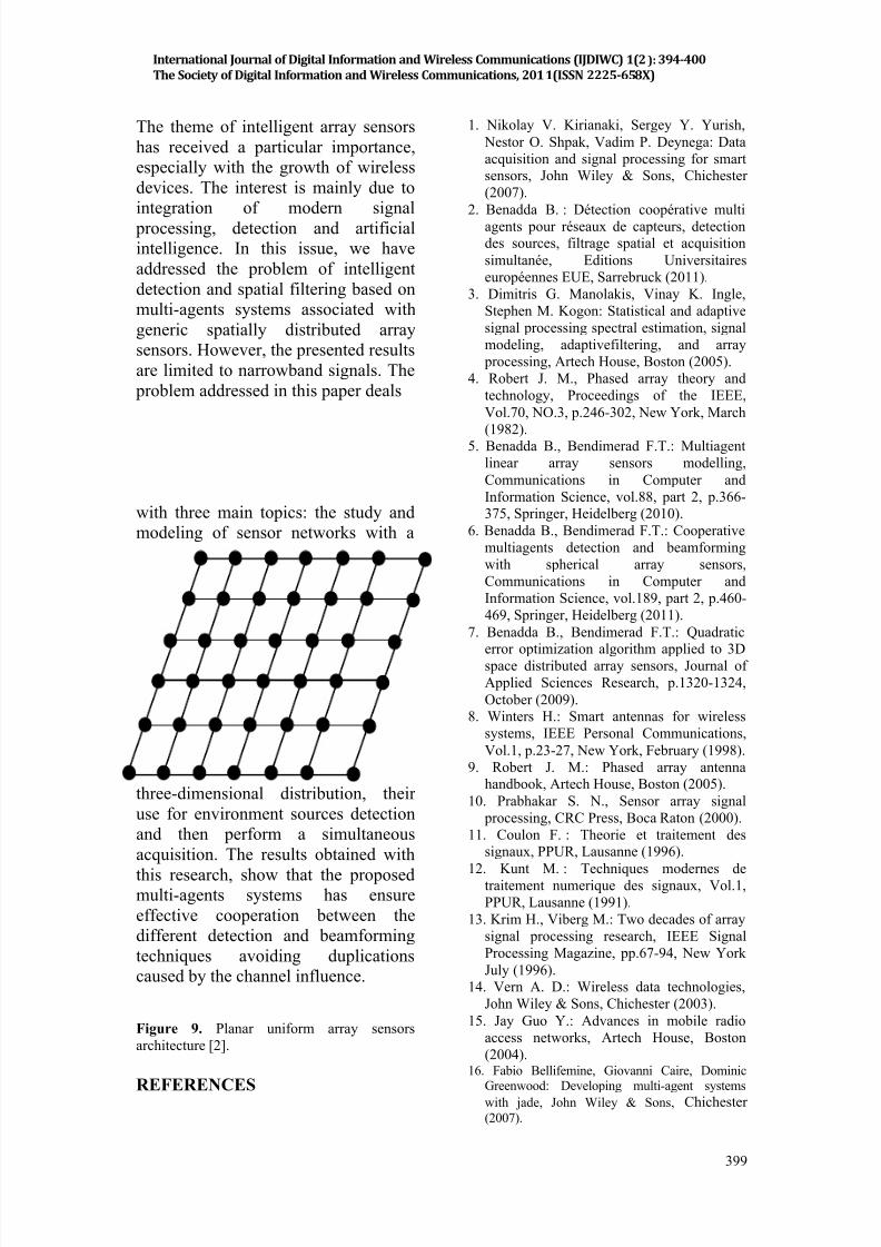
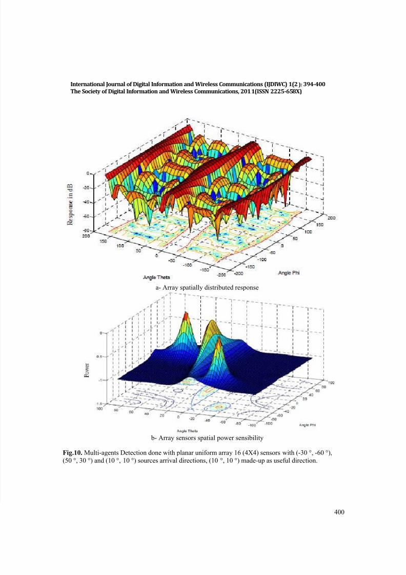
The multi-agents detection done with
regular planar array Figure 9, is shown
on Figure 10 for planar array of 16
elements (4 X 4). In this case three
sources were simulated according to
the directions (-30 °, -60 °), (50 °, 30 °)
and (10 °, 10 °). The directivity
obtained and the detected directions
represented in Fig.10 show that the
multi-agents reacts according to the
environment directions.
6 CONCLUSION
International Journal of Digital Information and Wireless Communications (IJDIWC) 1(2): 394-400
The Society of Digital Information and Wireless Communications, 2011(ISSN 2225-658X)
8/12/2019 COOPERATIVE MULTI-AGENTS DETECTION WITH SPATIALLY DISTRIBUTED ARRAY SENSORS
http://slidepdf.com/reader/full/cooperative-multi-agents-detection-with-spatially-distributed-array-sensors 6/7
8/12/2019 COOPERATIVE MULTI-AGENTS DETECTION WITH SPATIALLY DISTRIBUTED ARRAY SENSORS
http://slidepdf.com/reader/full/cooperative-multi-agents-detection-with-spatially-distributed-array-sensors 7/7
400
a- Array spatially distributed response
b- Array sensors spatial power sensibility
Fig.10. Multi-agents Detection done with planar uniform array 16 (4X4) sensors with (-30 °, -60 °),
(50 °, 30 °) and (10 °, 10 °) sources arrival directions, (10 °, 10 °) made-up as useful direction.
International Journal of Digital Information and Wireless Communications (IJDIWC) 1(2): 394-400
The Society of Digital Information and Wireless Communications, 2011(ISSN 2225-658X)
Top Related