


Languages
Pages
Legal

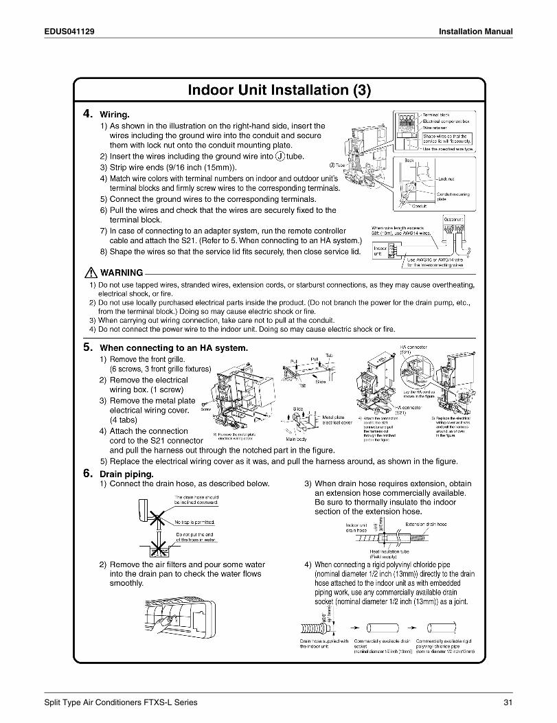
EDUS041129
FTXS-L Series
- Cooling Only / Heat Pump -
EDUS041129
Split TypeAir Conditioners
FTXS-L Series
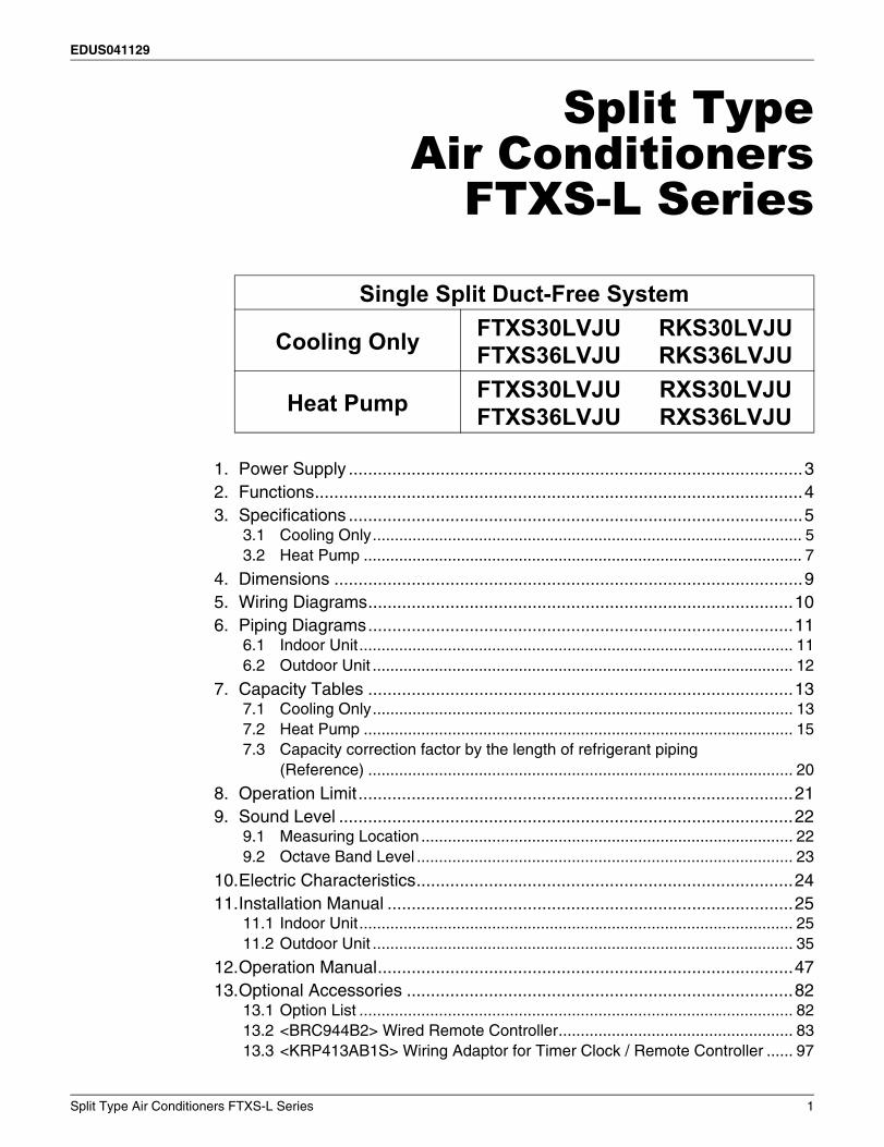
1. Power Supply ..............................................................................................32. Functions.....................................................................................................43. Specifications ..............................................................................................5
3.1 Cooling Only................................................................................................. 53.2 Heat Pump ................................................................................................... 7
4. Dimensions .................................................................................................95. Wiring Diagrams........................................................................................106. Piping Diagrams........................................................................................11
6.1 Indoor Unit.................................................................................................. 116.2 Outdoor Unit ............................................................................................... 12
7. Capacity Tables ........................................................................................137.1 Cooling Only............................................................................................... 137.2 Heat Pump ................................................................................................. 157.3 Capacity correction factor by the length of refrigerant piping
(Reference) ................................................................................................ 20
8. Operation Limit..........................................................................................219. Sound Level ..............................................................................................22
9.1 Measuring Location .................................................................................... 229.2 Octave Band Level ..................................................................................... 23
10.Electric Characteristics..............................................................................2411.Installation Manual ....................................................................................25
11.1 Indoor Unit.................................................................................................. 2511.2 Outdoor Unit ............................................................................................... 35
12.Operation Manual......................................................................................4713.Optional Accessories ................................................................................82
13.1 Option List .................................................................................................. 8213.2 <BRC944B2> Wired Remote Controller..................................................... 8313.3 <KRP413AB1S> Wiring Adaptor for Timer Clock / Remote Controller ...... 97
Single Split Duct-Free System
Cooling OnlyFTXS30LVJUFTXS36LVJU
RKS30LVJURKS36LVJU
Heat PumpFTXS30LVJUFTXS36LVJU
RXS30LVJURXS36LVJU
Split Type Air Conditioners FTXS-L Series 1
EDUS041129
13.4 <KRP928BB2S> Interface Adaptor for DIII-NET (Residential Air Conditioner) .................................................................... 101
13.5 <KPW5E112> Air Direction Adjustment Grille.......................................... 10413.6 <KKP945A4> Drain Plug.......................................................................... 106
2 Split Type Air Conditioners FTXS-L Series
EDUS041129 Power Supply
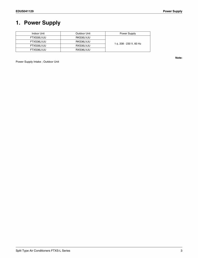
1. Power Supply
Note:Power Supply Intake ; Outdoor Unit
Indoor Unit Outdoor Unit Power Supply
FTXS30LVJU RKS30LVJU
1 , 208 - 230 V, 60 HzFTXS36LVJU RKS36LVJU
FTXS30LVJU RXS30LVJU
FTXS36LVJU RXS36LVJU
Split Type Air Conditioners FTXS-L Series 3
Functions EDUS041129
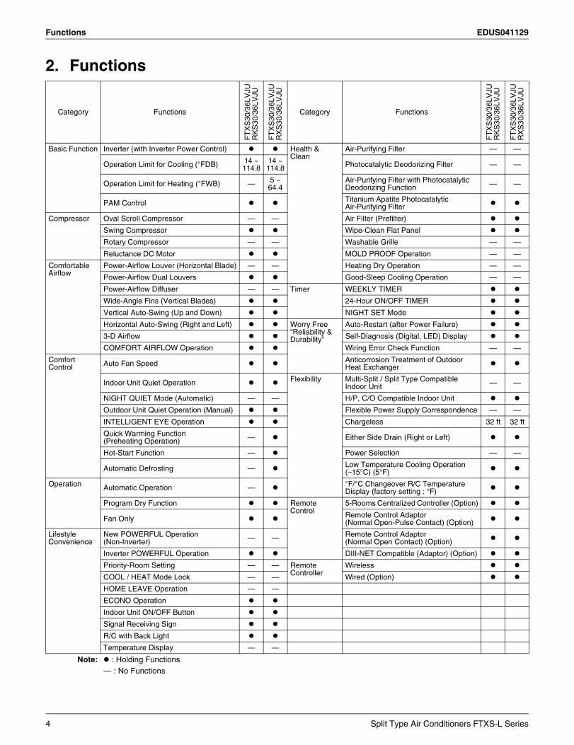
2. Functions
Category Functions
FT
XS
30/3
6LV
JUR
KS
30/3
6LV
JU
FT
XS
30/3
6LV
JUR
XS
30/3
6LV
JU
Category Functions
FT
XS
30/3
6LV
JUR
KS
30/3
6LV
JU
FT
XS
30/3
6LV
JUR
XS
30/3
6LV
JU
Basic Function Inverter (with Inverter Power Control) Health & Clean
Air-Purifying Filter — —
Operation Limit for Cooling (°FDB) 14 ~114.8
14 ~114.8 Photocatalytic Deodorizing Filter — —
Operation Limit for Heating (°FWB) — 5 ~64.4
Air-Purifying Filter with Photocatalytic Deodorizing Function — —
PAM Control Titanium Apatite Photocatalytic Air-Purifying Filter
Compressor Oval Scroll Compressor — — Air Filter (Prefilter)
Swing Compressor Wipe-Clean Flat Panel
Rotary Compressor — — Washable Grille — —
Reluctance DC Motor MOLD PROOF Operation — —
Comfortable Airflow
Power-Airflow Louver (Horizontal Blade) — — Heating Dry Operation — —
Power-Airflow Dual Louvers Good-Sleep Cooling Operation — —
Power-Airflow Diffuser — — Timer WEEKLY TIMER
Wide-Angle Fins (Vertical Blades) 24-Hour ON/OFF TIMER
Vertical Auto-Swing (Up and Down) NIGHT SET Mode
Horizontal Auto-Swing (Right and Left) Worry Free “Reliability & Durability”
Auto-Restart (after Power Failure)
3-D Airflow Self-Diagnosis (Digital, LED) Display
COMFORT AIRFLOW Operation Wiring Error Check Function — —
Comfort Control Auto Fan Speed Anticorrosion Treatment of Outdoor
Heat Exchanger
Indoor Unit Quiet Operation Flexibility Multi-Split / Split Type Compatible Indoor Unit — —
NIGHT QUIET Mode (Automatic) — — H/P, C/O Compatible Indoor Unit
Outdoor Unit Quiet Operation (Manual) Flexible Power Supply Correspondence — —
INTELLIGENT EYE Operation Chargeless 32 ft 32 ft
Quick Warming Function(Preheating Operation) — Either Side Drain (Right or Left)
Hot-Start Function — Power Selection — —
Automatic Defrosting — Low Temperature Cooling Operation(–15°C) (5°F)
Operation Automatic Operation — °F/°C Changeover R/C Temperature Display (factory setting : °F)
Program Dry Function Remote Control
5-Rooms Centralized Controller (Option)
Fan Only Remote Control Adaptor(Normal Open-Pulse Contact) (Option)
Lifestyle Convenience
New POWERFUL Operation(Non-Inverter) — — Remote Control Adaptor
(Normal Open Contact) (Option)
Inverter POWERFUL Operation DIII-NET Compatible (Adaptor) (Option)
Priority-Room Setting — — Remote Controller
Wireless
COOL / HEAT Mode Lock — — Wired (Option)
HOME LEAVE Operation — —
ECONO Operation
Indoor Unit ON/OFF Button
Signal Receiving Sign
R/C with Back Light
Temperature Display — —
Note: : Holding Functions— : No Functions
4 Split Type Air Conditioners FTXS-L Series
EDUS041129 Specifications
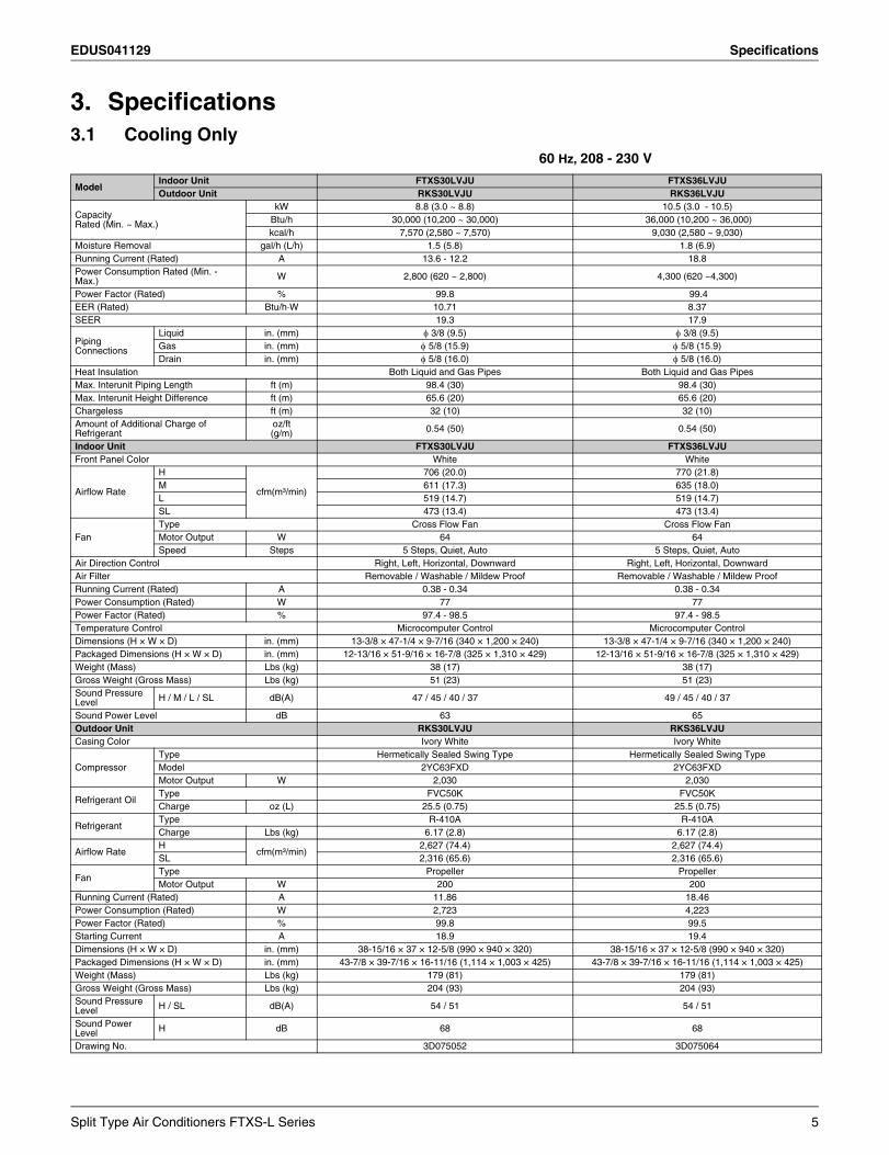
3. Specifications3.1 Cooling Only 60 Hz, 208 - 230 V
ModelIndoor Unit FTXS30LVJU FTXS36LVJUOutdoor Unit RKS30LVJU RKS36LVJU
Capacity Rated (Min. ~ Max.)
kW 8.8 (3.0 ~ 8.8) 10.5 (3.0 - 10.5)Btu/h 30,000 (10,200 ~ 30,000) 36,000 (10,200 ~ 36,000)kcal/h 7,570 (2,580 ~ 7,570) 9,030 (2,580 ~ 9,030)
Moisture Removal gal/h (L/h) 1.5 (5.8) 1.8 (6.9)Running Current (Rated) A 13.6 - 12.2 18.8Power Consumption Rated (Min. - Max.) W 2,800 (620 ~ 2,800) 4,300 (620 ~4,300)
Power Factor (Rated) % 99.8 99.4EER (Rated) Btu/h·W 10.71 8.37 SEER 19.3 17.9
Piping Connections
Liquid in. (mm) 3/8 (9.5) 3/8 (9.5)Gas in. (mm) 5/8 (15.9) 5/8 (15.9)Drain in. (mm) 5/8 (16.0) 5/8 (16.0)
Heat Insulation Both Liquid and Gas Pipes Both Liquid and Gas PipesMax. Interunit Piping Length ft (m) 98.4 (30) 98.4 (30)Max. Interunit Height Difference ft (m) 65.6 (20) 65.6 (20)Chargeless ft (m) 32 (10) 32 (10)Amount of Additional Charge of Refrigerant
oz/ft (g/m) 0.54 (50) 0.54 (50)
Indoor Unit FTXS30LVJU FTXS36LVJUFront Panel Color White White
Airflow Rate
H
cfm(m³/min)
706 (20.0) 770 (21.8)M 611 (17.3) 635 (18.0)L 519 (14.7) 519 (14.7)SL 473 (13.4) 473 (13.4)
FanType Cross Flow Fan Cross Flow FanMotor Output W 64 64Speed Steps 5 Steps, Quiet, Auto 5 Steps, Quiet, Auto
Air Direction Control Right, Left, Horizontal, Downward Right, Left, Horizontal, DownwardAir Filter Removable / Washable / Mildew Proof Removable / Washable / Mildew ProofRunning Current (Rated) A 0.38 - 0.34 0.38 - 0.34Power Consumption (Rated) W 77 77Power Factor (Rated) % 97.4 - 98.5 97.4 - 98.5Temperature Control Microcomputer Control Microcomputer ControlDimensions (H × W × D) in. (mm) 13-3/8 × 47-1/4 × 9-7/16 (340 × 1,200 × 240) 13-3/8 × 47-1/4 × 9-7/16 (340 × 1,200 × 240)Packaged Dimensions (H × W × D) in. (mm) 12-13/16 × 51-9/16 × 16-7/8 (325 × 1,310 × 429) 12-13/16 × 51-9/16 × 16-7/8 (325 × 1,310 × 429)Weight (Mass) Lbs (kg) 38 (17) 38 (17)Gross Weight (Gross Mass) Lbs (kg) 51 (23) 51 (23)Sound Pressure Level H / M / L / SL dB(A) 47 / 45 / 40 / 37 49 / 45 / 40 / 37
Sound Power Level dB 63 65Outdoor Unit RKS30LVJU RKS36LVJUCasing Color Ivory White Ivory White
CompressorType Hermetically Sealed Swing Type Hermetically Sealed Swing TypeModel 2YC63FXD 2YC63FXDMotor Output W 2,030 2,030
Refrigerant OilType FVC50K FVC50KCharge oz (L) 25.5 (0.75) 25.5 (0.75)
RefrigerantType R-410A R-410ACharge Lbs (kg) 6.17 (2.8) 6.17 (2.8)
Airflow RateH
cfm(m³/min) 2,627 (74.4) 2,627 (74.4)
SL 2,316 (65.6) 2,316 (65.6)
FanType Propeller PropellerMotor Output W 200 200
Running Current (Rated) A 11.86 18.46Power Consumption (Rated) W 2,723 4,223Power Factor (Rated) % 99.8 99.5Starting Current A 18.9 19.4Dimensions (H × W × D) in. (mm) 38-15/16 × 37 × 12-5/8 (990 × 940 × 320) 38-15/16 × 37 × 12-5/8 (990 × 940 × 320)Packaged Dimensions (H × W × D) in. (mm) 43-7/8 × 39-7/16 × 16-11/16 (1,114 × 1,003 × 425) 43-7/8 × 39-7/16 × 16-11/16 (1,114 × 1,003 × 425)Weight (Mass) Lbs (kg) 179 (81) 179 (81)Gross Weight (Gross Mass) Lbs (kg) 204 (93) 204 (93)Sound Pressure Level H / SL dB(A) 54 / 51 54 / 51
Sound Power Level H dB 68 68
Drawing No. 3D075052 3D075064
Split Type Air Conditioners FTXS-L Series 5
Specifications EDUS041129
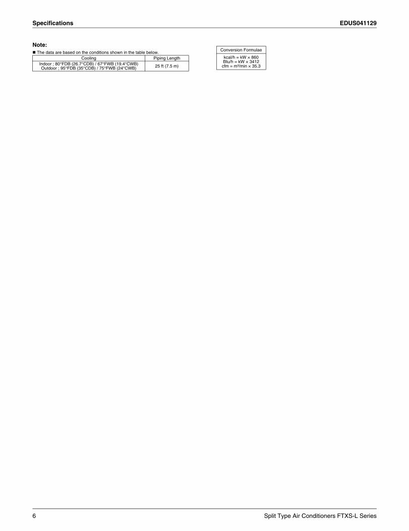
Note: The data are based on the conditions shown in the table below.
Cooling Piping LengthIndoor ; 80°FDB (26.7°CDB) / 67°FWB (19.4°CWB)Outdoor ; 95°FDB (35°CDB) / 75°FWB (24°CWB) 25 ft (7.5 m)
Conversion Formulae
kcal/h = kW × 860Btu/h = kW × 3412
cfm = m³/min × 35.3
6 Split Type Air Conditioners FTXS-L Series
EDUS041129 Specifications
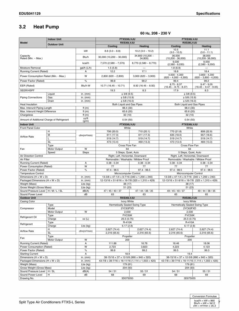
3.2 Heat Pump 60 Hz, 208 - 230 V
ModelIndoor Unit FTXS30LVJU FTXS36LVJU
Outdoor UnitRXS30LVJU RXS36LVJU
Cooling Heating Cooling Heating
Capacity Rated (Min. ~ Max.)
kW 8.8 (3.0 ~ 8.8) 10.2 (3.0 ~ 10.2) 10.5 (3.0 - 10.5)
11.1 (3.0 - 11.1)
Btu/h 30,000 (10,200 ~ 30,000) 34,800 (10,200 ~ 34,800)
36,000(10,200 - 36,000)
38,000(10,200- 38,000)
kcal/h 7,570 (2,580 ~ 7,570) 8,770 (2,580 ~ 8,770) 9,030(2,580 - 9,030)
9,550(2,580 - 9,550)
Moisture Removal gal/h (L/h) 1.5 (5.8) — 1.8 (6.9) —Running Current (Rated) A 12.2 17.1 18.8 18.4
Power Consumption Rated (Min. - Max.) W 2,800 (620 ~ 2,800) 3,900 (620 ~ 3,900) 4,000 - 4,300 (620 ~ 4,000 - 4,300)
3,800 - 4,200(620 ~ 3,800 - 4,200)
Power Factor (Rated) % 99.8 99.2 99.4 99.2
EER (Rated) Btu/h·W 10.71 (16.45 ~ 10.71) 8.92 (16.45 ~ 8.92) 8.75 - 8.37(16.45 ~ 8.75 - 8.37)
9.47 - 9.05(16.45 ~ 9.47 - 9.05)
SEER/HSPF 19.3 8.3 17.9 8.3
Piping ConnectionsLiquid in. (mm) 3/8 (9.5) 3/8 (9.5)Gas in. (mm) 5/8 (15.9) 5/8 (15.9)Drain in. (mm) 5/8 (16.0) 5/8 (16.0)
Heat Insulation Both Liquid and Gas Pipes Both Liquid and Gas PipesMax. Interunit Piping Length ft (m) 98.4 (30) 98.4 (30)Max. Interunit Height Difference ft (m) 65.6 (20) 65.6 (20)Chargeless ft (m) 32 (10) 32 (10)
Amount of Additional Charge of Refrigerant oz/ft (g/m) 0.54 (50) 0.54 (50)
Indoor Unit FTXS30LVJU FTXS36LVJUFront Panel Color White White
Airflow Rate
H
cfm(m³/min)
706 (20.0) 710 (20.1) 770 (21.8) 808 (22.9)M 611 (17.3) 611 (17.3) 635 (18.0) 657 (18.6)L 519 (14.7) 519 (14.7) 519 (14.7) 519 (14.7)SL 473 (13.4) 469 (13.3) 473 (13.4) 469 (13.3)
FanType Cross Flow Fan Cross Flow FanMotor Output W 64 64Speed Steps 5 Steps, Quiet, Auto 5 Steps, Quiet, Auto
Air Direction Control Right, Left, Horizontal, Downward Right, Left, Horizontal, DownwardAir Filter Removable / Washable / Mildew Proof Removable / Washable / Mildew ProofRunning Current (Rated) A 0.38 - 0.34 0.38 - 0.34 0.38 - 0.34 0.38 - 0.34Power Consumption (Rated) W 77 77 77 77Power Factor (Rated) % 97.4 - 98.5 97.4 - 98.5 97.4 - 98.5 97.4 - 98.5Temperature Control Microcomputer Control Microcomputer ControlDimensions (H × W × D) in. (mm) 13-3/8 × 47-1/4 × 9-7/16 (340 × 1,200 × 240) 13-3/8 × 47-1/4 × 9-7/16 (340 × 1,200 × 240)Packaged Dimensions (H × W × D) in. (mm) 12-13/16 × 51-9/16 × 16-7/8 (325 × 1,310 × 429) 12-13/16 × 51-9/16 × 16-7/8 (325 × 1,310 × 429)Weight (Mass) Lbs (kg) 38 (17) 38 (17)Gross Weight (Gross Mass) Lbs (kg) 51 (23) 51 (23)Sound Pressure Level H / M / L / SL dB(A) 47 / 45 / 40 / 37 47 / 44 / 38 / 35 49 / 45 / 40 / 37 49 / 44 / 38 / 35Sound Power Level dB 63 63 65 65Outdoor Unit RXS30LVJU RXS36LVJUCasing Color Ivory White Ivory White
CompressorType Hermetically Sealed Swing Type Hermetically Sealed Swing TypeModel 2YC63FXD 2YC63FXDMotor Output W 2,030 2,030
Refrigerant OilType FVC50K FVC50KCharge oz (L) 25.5 (0.75) 25.5 (0.75)
RefrigerantType R-410A R-410ACharge Lbs (kg) 6.17 (2.8) 6.17 (2.8)
Airflow RateH
cfm(m³/min)2,627 (74.4) 2,627 (74.4) 2,627 (74.4) 2,627 (74.4)
SL 2,316 (65.6) 2,316 (65.6) 2,316 (65.6) 2,316 (65.6)
FanType Propeller PropellerMotor Output W 200 200
Running Current (Rated) A 111.86 16.76 18.46 18.06Power Consumption (Rated) W 2,723 3,823 4,223 4,123Power Factor (Rated) % 99.8 99.2 99.5 99.3Starting Current A 18.9 19.4Dimensions (H × W × D) in. (mm) 38-15/16 × 37 × 12-5/8 (990 × 940 × 320) 38-15/16 × 37 × 12-5/8 (990 × 940 × 320)Packaged Dimensions (H × W × D) in. (mm) 43-7/8 × 39-7/16 × 16-11/16 (1,114 × 1,003 × 425) 43-7/8 × 39-7/16 × 16-11/16 (1,114 × 1,003 × 425)Weight (Mass) Lbs (kg) 179 (81) 179 (81)Gross Weight (Gross Mass) Lbs (kg) 204 (93) 204 (93)Sound Pressure Level H / SL dB(A) 54 / 51 55 / 51 54 / 51 55 / 51Sound Power Level H dB 68 69 68 69Drawing No. 3D075050 3D075055
Split Type Air Conditioners FTXS-L Series 7
Conversion Formulae
kcal/h = kW × 860Btu/h = kW × 3412
cfm = m³/min × 35.3
Specifications EDUS041129
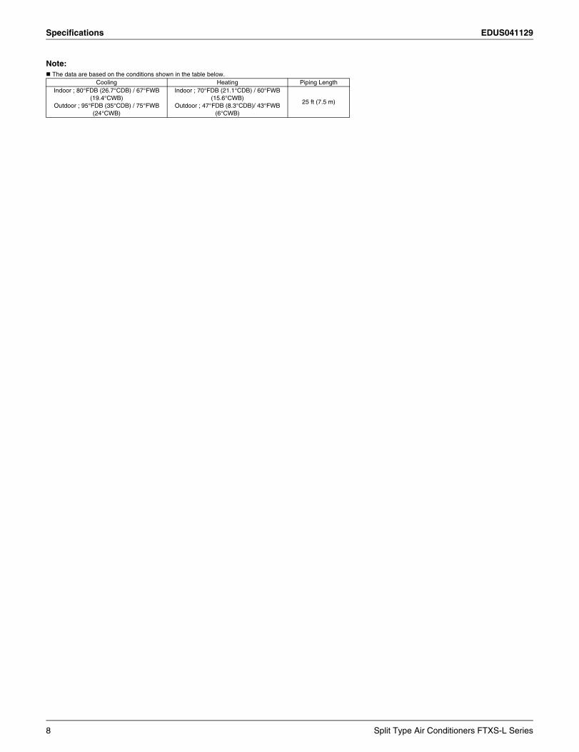
Note: The data are based on the conditions shown in the table below.
Cooling Heating Piping LengthIndoor ; 80°FDB (26.7°CDB) / 67°FWB
(19.4°CWB)Outdoor ; 95°FDB (35°CDB) / 75°FWB
(24°CWB)
Indoor ; 70°FDB (21.1°CDB) / 60°FWB (15.6°CWB)
Outdoor ; 47°FDB (8.3°CDB)/ 43°FWB (6°CWB)
25 ft (7.5 m)
8 Split Type Air Conditioners FTXS-L Series
EDUS041129 Dimensions
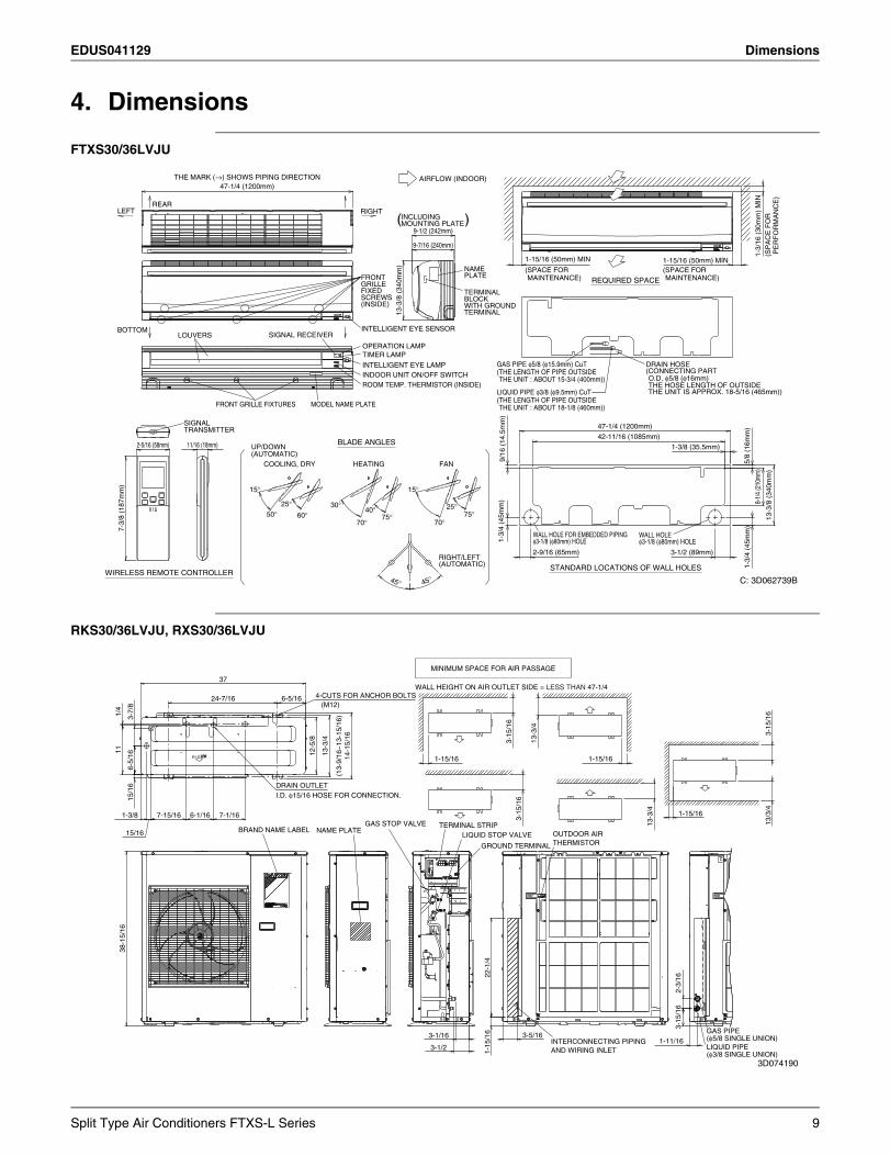
4. Dimensions
FTXS30/36LVJU
RKS30/36LVJU, RXS30/36LVJU
47-1/4 (1200mm)
7-3/
8 (1
87m
m)
1-3/
16 (
30m
m)
MIN
2-9/16 (65mm)
42-11/16 (1085mm)
1-15/16 (50mm) MIN1-15/16 (50mm) MIN
9/16
(14
.5m
m)
9-1/2 (242mm)
11/16 (18mm)
9-7/16 (240mm)
45°
2-5/16 (58mm)
8-1/
4 (2
10m
m)
47-1/4 (1200mm)
5/8
(16m
m)
1-3/8 (35.5mm)
45°
13-3
/8 (
340m
m)
1-3/
4 (4
5mm
)
3-1/2 (89mm)
1-3/
4 (4
5mm
)
13-3
/8 (
340m
m)
ROOM TEMP. THERMISTOR (INSIDE)
15°
OPERATION LAMP
φ3-1/8 (φ80mm) HOLEWALL HOLE FOR EMBEDDED PIPING
MAINTENANCE)(SPACE FOR
SIGNAL RECEIVER
FRONT GRILLE FIXTURES
WIRELESS REMOTE CONTROLLER
THE UNIT : ABOUT 15-3/4 (400mm))(THE LENGTH OF PIPE OUTSIDEGAS PIPE φ5/8 (φ15.9mm) CuT
30°
(AUTOMATIC)UP/DOWN
PLATENAME
(AUTOMATIC)RIGHT/LEFT
BLADE ANGLES
REAR
LOUVERS
INTELLIGENT EYE LAMP
REQUIRED SPACE
75°
THE UNIT : ABOUT 18-1/8 (460mm))(THE LENGTH OF PIPE OUTSIDELIQUID PIPE φ3/8 (φ9.5mm) CuT
RIGHT
PE
RF
OR
MA
NC
E)
(SP
AC
E F
OR
70°60°
HEATING FAN
BOTTOM
TERMINALWITH GROUNDBLOCKTERMINAL
THE MARK (→) SHOWS PIPING DIRECTION
INDOOR UNIT ON/OFF SWITCH
40°
LEFT
(INSIDE)SCREWSFIXEDGRILLEFRONT
70°
TRANSMITTERSIGNAL
75°
STANDARD LOCATIONS OF WALL HOLES
AIRFLOW (INDOOR)
( )MOUNTING PLATEINCLUDING
TIMER LAMP
COOLING, DRY
50°
INTELLIGENT EYE SENSOR
25°
MAINTENANCE)(SPACE FOR
25°
15°
MODEL NAME PLATE
φ3-1/8 (φ80mm) HOLEWALL HOLE
THE UNIT IS APPROX. 18-5/16 (465mm))THE HOSE LENGTH OF OUTSIDEO.D. φ5/8 (φ16mm)
(CONNECTING PARTDRAIN HOSE
C: 3D062739B
MINIMUM SPACE FOR AIR PASSAGE
37
4-CUTS FOR ANCHOR BOLTS6-5/1624-7/16(M12)
1/4
3-7/
8
3-15
/16
13-3
/4
3-15
/16
11 12-5
/8
13-3
/4
14-1
5/16
1-15/161-15/16
6-5/
16
(13-
9/16
~13
-15/
16)
DRAIN OUTLETI.D. φ15/16 HOSE FOR CONNECTION.15
/16
1-15/16
3-15
/16
1-3/8 7-1/166-1/167-15/16
13-3
/4
13/3
/4
TERMINAL STRIPGAS STOP VALVEBRAND NAME LABEL NAME PLATE15/16 OUTDOOR AIRLIQUID STOP VALVE
THERMISTORGROUND TERMINAL
38-1
5/16
22-1
/4
2-3/
163-
15/1
6
GAS PIPE3-5/163-1/16 (φ5/8 SINGLE UNION)1-11/16INTERCONNECTING PIPING
1-15
/16
3-1/2 LIQUID PIPEAND WIRING INLET(φ3/8 SINGLE UNION)
WALL HEIGHT ON AIR OUTLET SIDE = LESS THAN 47-1/4
3D074190
Split Type Air Conditioners FTXS-L Series 9
Wiring Diagrams EDUS041129
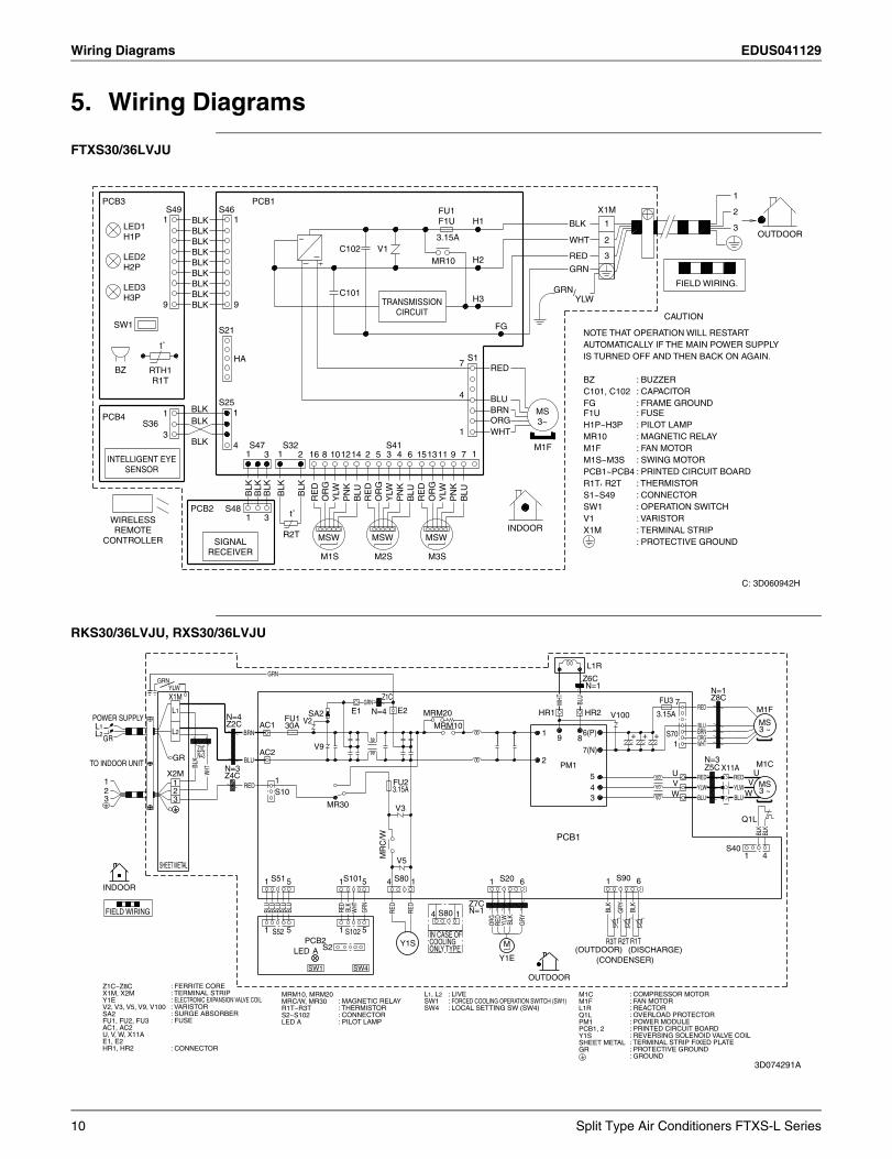
5. Wiring Diagrams
FTXS30/36LVJU
RKS30/36LVJU, RXS30/36LVJU
1
X1MPCB1PCB3
S46S49 2H1BLK1 1 BLK 1 3BLK
3.15A WHT~ OUTDOOR2BLK
C102 V1BLK RED 3H2MR10BLKGRNBLK
FIELD WIRING.BLKC101BLK H3
99 BLKCAUTION
FGSW1S21
t˚S1HA 7 REDBZ
4 BLUS25BLK MS
3~BRN1 1PCB4 BLK ORGS36
1 WHT3S41S47 S32BLK 4 M1F
121 16 14 111 73 18 15522 13 910 643
BLK
BLK
BLK
BLK
BLK
PN
K
PN
K
PN
K
BLU
BLU
BLU
RE
D
RE
D
RE
D
OR
G
OR
G
OR
G
YLW
YLW
YLW
S48PCB2 t˚1 3INDOOR
R2T MSW MSWMSW
M1S M3SM2S
GRN/YLW
SIGNAL RECEIVER
WIRELESS REMOTE
CONTROLLER
INTELLIGENT EYE SENSOR
RTH1 R1T
LED3 H3P
LED2 H2P
LED1 H1P
TRANSMISSION CIRCUIT
FU1 F1U
NOTE THAT OPERATION WILL RESTART AUTOMATICALLY IF THE MAIN POWER SUPPLY IS TURNED OFF AND THEN BACK ON AGAIN.
BZC101, C102FGF1UH1P~H3PMR10M1FM1S~M3SPCB1~PCB4R1T, R2TS1~S49SW1V1X1M
: BUZZER: CAPACITOR: FRAME GROUND: FUSE: PILOT LAMP: MAGNETIC RELAY: FAN MOTOR: SWING MOTOR: PRINTED CIRCUIT BOARD: THERMISTOR: CONNECTOR: OPERATION SWITCH: VARISTOR: TERMINAL STRIP: PROTECTIVE GROUND
C: 3D060942H
S80
IN CASE OFCOOLINGONLY TYPE
4 1
L1RGRN
Z6CGRNN=1YLW N=1
Z1CX1M Z8CFU3GRN 7BLU
WHT
RED M1FE1 N=4 E2L1 HR2SA2 HR1MRM20 3.15APOWER SUPPLY V100N=4 FU1 MSV2Z2C AC1 BLUMRM1030AL1 3 ~L2 BRN6(P)1BRNL2 S70+ ++9 8 ORG1 WHTV9 7(N)AC2Z3C
N=32 N=3BLUTO INDOOR UNIT BL
K
M1CZ5CPM1 X11AN=3 UWHT U
GR
X2M
GR
Z4C RED5 RED11 1 V V MSRED YLW4 YLW2FU23.15A2 3 ~S10 W W3 BLU3 BLU3
MR30 V3Q1L
BLK
BLK
PCB1S40
MR
C/W
41V5SHEET METAL
S90S51 S101 S80 S205 4 11 1 5 6161INDOOR
Z7CN=1RE
D
BLK
BLK
BLU
BLU
BLU
BLU
BLU
BLK
GRY
RED
RED
GRN
WHT
FIELD WIRINGt˚t˚ t˚OR
G
BLK
RED
GRY
YLW
1 51 S1025S52R1TR2TR3TPCB2 MY1SS2 (OUTDOOR) (DISCHARGE)LED A
Y1E (CONDENSER)SW4SW1
OUTDOORZ1C~Z8CX1M, X2MY1EV2, V3, V5, V9, V100SA2FU1, FU2, FU3AC1, AC2U, V, W, X11AE1, E2HR1, HR2
: FERRITE CORE: TERMINAL STRIP: ELECTRONIC EXPANSION VALVE COIL: VARISTOR: SURGE ABSORBER: FUSE
: CONNECTOR
MRM10, MRM20MRC/W, MR30R1T~R3TS2~S102LED A
: MAGNETIC RELAY: THERMISTOR: CONNECTOR: PILOT LAMP
L1, L2SW1SW4
: LIVE: FORCED COOLING OPERATION SWITCH (SW1): LOCAL SETTING SW (SW4)
M1CM1FL1RQ1LPM1PCB1, 2Y1SSHEET METALGR
: COMPRESSOR MOTOR: FAN MOTOR: REACTOR: OVERLOAD PROTECTOR: POWER MODULE: PRINTED CIRCUIT BOARD: REVERSING SOLENOID VALVE COIL: TERMINAL STRIP FIXED PLATE: PROTECTIVE GROUND: GROUND
3D074291A
10 Split Type Air Conditioners FTXS-L Series
EDUS041129 Piping Diagrams
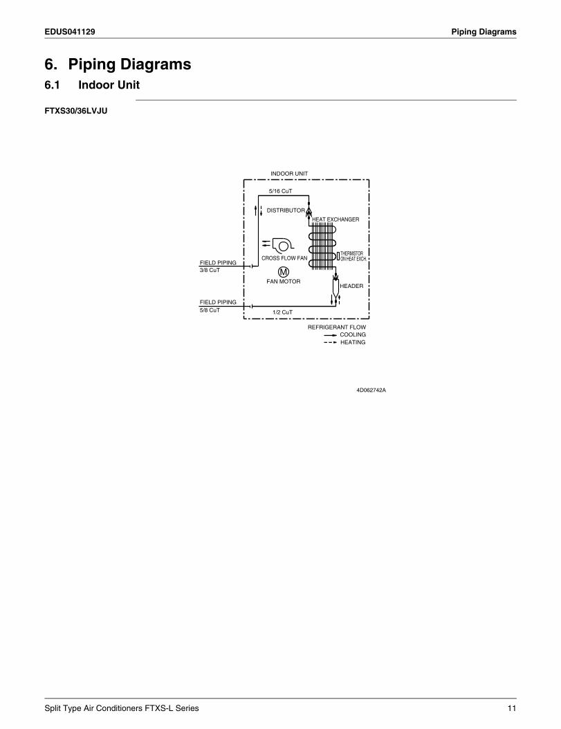
6. Piping Diagrams6.1 Indoor Unit
FTXS30/36LVJU
CROSS FLOW FAN ON HEAT EXCH.THERMISTOR
HEAT EXCHANGER
1/2 CuT5/8 CuT
HEADER
REFRIGERANT FLOW
INDOOR UNIT
HEATING
M
FIELD PIPING
COOLING
3/8 CuT
FAN MOTOR
FIELD PIPING
5/16 CuT
DISTRIBUTOR
4D062742A
Split Type Air Conditioners FTXS-L Series 11
Piping Diagrams EDUS041129
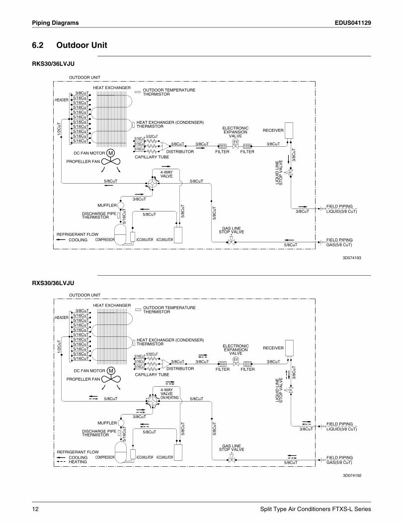
6.2 Outdoor Unit
RKS30/36LVJU
RXS30/36LVJU
OUTDOOR UNIT
HEAT EXCHANGER3/8CuT
OUTDOOR TEMPERATURETHERMISTOR
5/16CuTHEADER5/16CuT5/16CuT5/16CuT5/16CuT5/16CuT HEAT EXCHANGER (CONDENSER)
THERMISTOR5/16CuTRECEIVER
1/2C
uT
5/16CuT5/16CuT 5/32CuT5/16CuT5/16CuT EV5/16CuT 3/8CuT3/8CuT 3/8CuT
5/16CuT
ELECTRONIC
FILTERFILTERDISTRIBUTORDC FAN MOTOR
EXPANSION
MCAPILLARY TUBE
VALVE
3/8C
uT
PROPELLER FAN
LIQ
UID
LIN
ES
TO
P V
ALV
E
5/8CuT 5/8CuT
3/8CuT
MUFFLER FIELD PIPINGLIQUID(3/8 CuT)3/8CuT
5/8CuT 5/8C
uT
5/8C
uTDISCHARGE PIPETHERMISTOR
5/16
CuT
GAS LINESTOP VALVE
REFRIGERANT FLOWCOMPRESSORCOOLING FIELD PIPING
GAS(5/8 CuT)5/8CuT
4-WAYVALVE
ACCUMULATORACCUMULATOR
3D074193
OUTDOOR UNIT
HEAT EXCHANGER3/8CuT
OUTDOOR TEMPERATURETHERMISTOR
5/16CuTHEADER5/16CuT5/16CuT5/16CuT5/16CuT5/16CuT HEAT EXCHANGER (CONDENSER)
THERMISTOR5/16CuTRECEIVER
1/2C
uT
5/16CuT5/16CuT 5/32CuT5/16CuT5/16CuT EV5/16CuT 3/8CuT3/8CuT 3/8CuT
5/16CuT
ELECTRONIC
FILTERFILTERDISTRIBUTORDC FAN MOTOR
EXPANSION
MCAPILLARY TUBE
VALVE
3/8C
uT
PROPELLER FAN
LIQ
UID
LIN
ES
TO
P V
ALV
E
5/8CuT 5/8CuT
3/8CuT
MUFFLER FIELD PIPINGLIQUID(3/8 CuT)3/8CuT
5/8CuT 5/8C
uT
5/8C
uT
DISCHARGE PIPETHERMISTOR
5/16
CuT
GAS LINESTOP VALVE
REFRIGERANT FLOWCOMPRESSORCOOLING FIELD PIPING
HEATING GAS(5/8 CuT)5/8CuT
4-WAYVALVEON:HEATING
ACCUMULATORACCUMULATOR
3D074192
12 Split Type Air Conditioners FTXS-L Series
EDUS041129 Capacity Tables
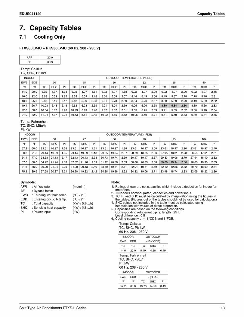
7. Capacity Tables7.1 Cooling Only
FTXS30LVJU + RKS30LVJU (60 Hz, 208 - 230 V)
AFR 20.0
BF 0.23
Temp: CelsiusTC, SHC, PI: kW
INDOOR OUTDOOR TEMPERATURE (°CDB)
EWB EDB 20 25 30 32 35 40
°C °C TC SHC PI TC SHC PI TC SHC PI TC SHC PI TC SHC PI TC SHC PI
14.0 20.0 6.92 4.97 1.38 6.92 4.97 1.61 6.92 4.97 1.88 6.92 4.97 2.00 6.92 4.97 2.20 6.92 4.97 2.46
16.0 22.0 8.63 5.59 1.85 8.63 5.59 2.18 8.60 5.58 2.57 8.44 5.49 2.66 8.19 5.37 2.78 7.78 5.16 2.81
18.0 25.0 9.83 6.19 2.17 9.42 5.99 2.38 9.01 5.78 2.59 8.84 5.70 2.67 8.60 5.59 2.79 8.19 5.39 2.82
19.4 26.7 10.03 6.43 2.18 9.62 6.23 2.39 9.21 6.04 2.59 9.05 5.96 2.68 8.80 5.84 2.80 8.39 5.66 2.83
22.0 30.0 10.64 6.17 2.20 10.23 5.99 2.40 9.82 5.82 2.61 9.65 5.75 2.69 9.41 5.65 2.82 9.00 5.48 2.84
24.0 32.0 11.04 5.97 2.21 10.63 5.81 2.42 10.22 5.65 2.62 10.06 5.59 2.71 9.81 5.49 2.83 9.40 5.34 2.86
Temp: FahrenheitTC, SHC: kBtu/hPI: kW
INDOOR OUTDOOR TEMPERATURE (°FDB)
EWB EDB 68 77 86 90 95 104
°F °F TC SHC PI TC SHC PI TC SHC PI TC SHC PI TC SHC PI TC SHC PI
57.2 68.0 23.61 16.97 1.38 23.61 16.97 1.61 23.61 16.97 1.88 23.61 16.97 2.00 23.61 16.97 2.20 23.61 16.97 2.46
60.8 71.6 29.44 19.09 1.85 29.44 19.09 2.18 29.35 19.04 2.57 28.79 18.75 2.66 27.95 18.31 2.78 26.55 17.61 2.81
64.4 77.0 33.53 21.13 2.17 32.13 20.43 2.38 30.73 19.74 2.59 30.17 19.47 2.67 29.33 19.06 2.79 27.94 18.40 2.82
67.0 80.0 34.22 21.94 2.18 32.82 21.26 2.39 31.42 20.59 2.59 30.86 20.33 2.68 30.00 19.94 2.80 28.63 19.30 2.83
71.6 86.0 36.29 21.04 2.20 34.90 20.43 2.40 33.50 19.84 2.61 32.94 19.61 2.69 32.10 19.26 2.82 30.70 18.69 2.84
75.2 89.6 37.68 20.37 2.21 36.28 19.82 2.42 34.88 19.28 2.62 34.32 19.06 2.71 33.48 18.74 2.83 32.09 18.22 2.86
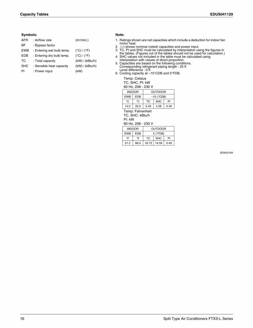
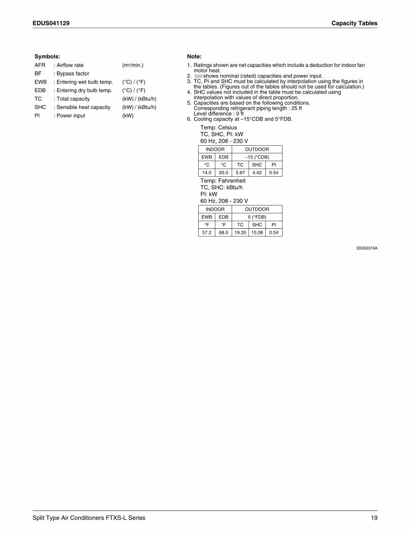
Symbols: Note:AFR : Airflow rate (m3/min.) 1. Ratings shown are net capacities which include a deduction for indoor fan
motor heat.2. shows nominal (rated) capacities and power input.3. TC, PI and SHC must be calculated by interpolation using the figures in
the tables. (Figures out of the tables should not be used for calculation.)4. SHC values not included in the table must be calculated using
interpolation with values of direct proportion.5. Capacities are based on the following conditions.
Corresponding refrigerant piping length : 25 ftLevel difference : 0 ft
6. Cooling capacity at –15°CDB and 5°FDB.
BF : Bypass factorEWB : Entering wet bulb temp. (°C) / (°F)EDB : Entering dry bulb temp. (°C) / (°F)TC : Total capacity (kW) / (kBtu/h)SHC : Sensible heat capacity (kW) / (kBtu/h)PI : Power input (kW)
Temp: CelsiusTC, SHC, PI: kW60 Hz, 208 - 230 V
INDOOR OUTDOOR
EWB EDB –15 (°CDB)
°C °C TC SHC PI
14.0 20.0 5.49 4.28 0.49
Temp: FahrenheitTC, SHC: kBtu/hPI: kW60 Hz, 208 - 230 V
INDOOR OUTDOOR
EWB EDB 5 (°FDB)
°F °F TC SHC PI
57.2 68.0 18.73 14.59 0.49
Split Type Air Conditioners FTXS-L Series 13
Capacity Tables EDUS041129
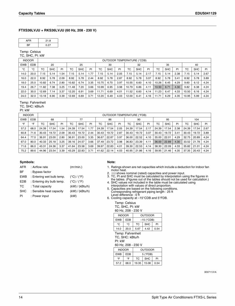
FTXS36LVJU + RKS36LVJU (60 Hz, 208 - 230 V)
3D071131A
AFR 21.8
BF 0.27
Temp: CelsiusTC, SHC, PI: kW
INDOOR OUTDOOR TEMPERATURE (°CDB)
EWB EDB 20 25 30 32 35 40
°C °C TC SHC PI TC SHC PI TC SHC PI TC SHC PI TC SHC PI TC SHC PI
14.0 20.0 7.15 5.14 1.54 7.15 5.14 1.77 7.15 5.14 2.05 7.15 5.14 2.17 7.15 5.14 2.38 7.15 5.14 2.67
16.0 22.0 8.92 5.78 2.09 8.92 5.78 2.44 8.92 5.78 2.87 8.92 5.78 3.07 8.92 5.78 3.41 8.92 5.78 3.89
18.0 25.0 10.82 6.74 2.80 10.82 6.74 3.35 10.75 6.70 3.97 10.55 6.60 4.10 10.26 6.45 4.29 9.60 6.12 4.24
19.4 26.7 11.82 7.38 3.25 11.48 7.20 3.66 10.99 6.95 3.98 10.79 6.86 4.11 10.50 6.71 4.30 9.82 6.38 4.24
22.0 30.0 12.69 7.14 3.37 12.20 6.91 3.69 11.71 6.69 4.01 11.52 6.60 4.14 11.23 6.47 4.33 10.50 6.16 4.24
24.0 32.0 13.18 6.90 3.39 12.69 6.69 3.71 12.20 6.49 4.03 12.00 6.41 4.16 11.71 6.29 4.35 10.95 5.99 4.24
Temp: FahrenheitTC, SHC: kBtu/hPI: kW
INDOOR OUTDOOR TEMPERATURE (°FDB)
EWB EDB 68 77 86 90 95 104
°F °F TC SHC PI TC SHC PI TC SHC PI TC SHC PI TC SHC PI TC SHC PI
57.2 68.0 24.39 17.54 1.54 24.39 17.54 1.77 24.39 17.54 2.05 24.39 17.54 2.17 24.39 17.54 2.38 24.39 17.54 2.67
60.8 71.6 30.43 19.72 2.09 30.43 19.72 2.44 30.43 19.72 2.87 30.43 19.72 3.07 30.43 19.72 3.41 30.43 19.72 3.89
64.4 77.0 36.91 23.00 2.80 36.91 23.00 3.35 36.67 22.87 3.97 36.00 22.52 4.10 35.00 22.01 4.29 32.75 20.89 4.24
67.0 80.0 40.33 25.18 3.25 39.16 24.57 3.66 37.49 23.72 3.98 36.83 23.39 4.11 36.00 22.89 4.30 33.52 21.78 4.24
71.6 86.0 43.31 24.36 3.37 41.64 23.58 3.69 39.97 22.83 4.01 39.30 22.53 4.14 38.30 22.09 4.33 35.82 21.01 4.24
75.2 89.6 44.96 23.54 3.39 43.29 22.83 3.71 41.62 22.14 4.03 40.95 21.86 4.16 39.95 21.46 4.35 37.35 20.43 4.24
Symbols: Note:
AFR : Airflow rate (m3/min.) 1. Ratings shown are net capacities which include a deduction for indoor fan motor heat.
2. shows nominal (rated) capacities and power input.3. TC, PI and SHC must be calculated by interpolation using the figures in
the tables. (Figures out of the tables should not be used for calculation.)4. SHC values not included in the table must be calculated using
interpolation with values of direct proportion.5. Capacities are based on the following conditions.
Corresponding refrigerant piping length : 25 ftLevel difference : 0 ft
6. Cooling capacity at –15°CDB and 5°FDB.
BF : Bypass factor
EWB : Entering wet bulb temp. (°C) / (°F)
EDB : Entering dry bulb temp. (°C) / (°F)
TC : Total capacity (kW) / (kBtu/h)
SHC : Sensible heat capacity (kW) / (kBtu/h)
PI : Power input (kW)
Temp: CelsiusTC, SHC, PI: kW60 Hz, 208 - 230 V
INDOOR OUTDOOR
EWB EDB –15 (°CDB)
°C °C TC SHC PI
14.0 20.0 5.67 4.42 0.54
Temp: FahrenheitTC, SHC: kBtu/hPI: kW60 Hz, 208 - 230 V
INDOOR OUTDOOR
EWB EDB 5 (°FDB)
°F °F TC SHC PI
57.2 68.0 19.35 15.08 0.54
14 Split Type Air Conditioners FTXS-L Series
EDUS041129 Capacity Tables
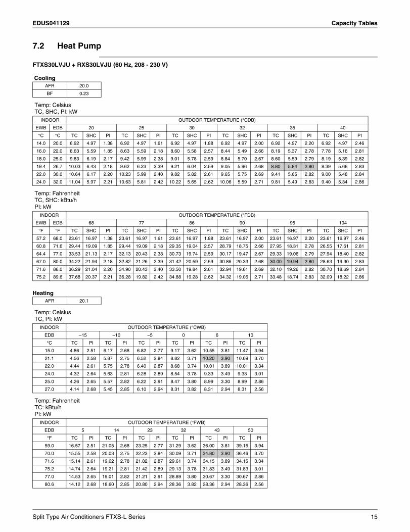
7.2 Heat Pump
FTXS30LVJU + RXS30LVJU (60 Hz, 208 - 230 V)
Cooling
Heating
AFR 20.0
BF 0.23
Temp: CelsiusTC, SHC, PI: kW
INDOOR OUTDOOR TEMPERATURE (°CDB)
EWB EDB 20 25 30 32 35 40
°C °C TC SHC PI TC SHC PI TC SHC PI TC SHC PI TC SHC PI TC SHC PI
14.0 20.0 6.92 4.97 1.38 6.92 4.97 1.61 6.92 4.97 1.88 6.92 4.97 2.00 6.92 4.97 2.20 6.92 4.97 2.46
16.0 22.0 8.63 5.59 1.85 8.63 5.59 2.18 8.60 5.58 2.57 8.44 5.49 2.66 8.19 5.37 2.78 7.78 5.16 2.81
18.0 25.0 9.83 6.19 2.17 9.42 5.99 2.38 9.01 5.78 2.59 8.84 5.70 2.67 8.60 5.59 2.79 8.19 5.39 2.82
19.4 26.7 10.03 6.43 2.18 9.62 6.23 2.39 9.21 6.04 2.59 9.05 5.96 2.68 8.80 5.84 2.80 8.39 5.66 2.83
22.0 30.0 10.64 6.17 2.20 10.23 5.99 2.40 9.82 5.82 2.61 9.65 5.75 2.69 9.41 5.65 2.82 9.00 5.48 2.84
24.0 32.0 11.04 5.97 2.21 10.63 5.81 2.42 10.22 5.65 2.62 10.06 5.59 2.71 9.81 5.49 2.83 9.40 5.34 2.86
Temp: FahrenheitTC, SHC: kBtu/hPI: kW
INDOOR OUTDOOR TEMPERATURE (°FDB)
EWB EDB 68 77 86 90 95 104
°F °F TC SHC PI TC SHC PI TC SHC PI TC SHC PI TC SHC PI TC SHC PI
57.2 68.0 23.61 16.97 1.38 23.61 16.97 1.61 23.61 16.97 1.88 23.61 16.97 2.00 23.61 16.97 2.20 23.61 16.97 2.46
60.8 71.6 29.44 19.09 1.85 29.44 19.09 2.18 29.35 19.04 2.57 28.79 18.75 2.66 27.95 18.31 2.78 26.55 17.61 2.81
64.4 77.0 33.53 21.13 2.17 32.13 20.43 2.38 30.73 19.74 2.59 30.17 19.47 2.67 29.33 19.06 2.79 27.94 18.40 2.82
67.0 80.0 34.22 21.94 2.18 32.82 21.26 2.39 31.42 20.59 2.59 30.86 20.33 2.68 30.00 19.94 2.80 28.63 19.30 2.83
71.6 86.0 36.29 21.04 2.20 34.90 20.43 2.40 33.50 19.84 2.61 32.94 19.61 2.69 32.10 19.26 2.82 30.70 18.69 2.84
75.2 89.6 37.68 20.37 2.21 36.28 19.82 2.42 34.88 19.28 2.62 34.32 19.06 2.71 33.48 18.74 2.83 32.09 18.22 2.86
AFR 20.1
Temp: CelsiusTC, PI: kW
INDOOR OUTDOOR TEMPERATURE (°CWB)
EDB –15 –10 –5 0 6 10
°C TC PI TC PI TC PI TC PI TC PI TC PI
15.0 4.86 2.51 6.17 2.68 6.82 2.77 9.17 3.62 10.55 3.81 11.47 3.94
21.1 4.56 2.58 5.87 2.75 6.52 2.84 8.82 3.71 10.20 3.90 10.69 3.70
22.0 4.44 2.61 5.75 2.78 6.40 2.87 8.68 3.74 10.01 3.89 10.01 3.34
24.0 4.32 2.64 5.63 2.81 6.28 2.89 8.54 3.78 9.33 3.49 9.33 3.01
25.0 4.26 2.65 5.57 2.82 6.22 2.91 8.47 3.80 8.99 3.30 8.99 2.86
27.0 4.14 2.68 5.45 2.85 6.10 2.94 8.31 3.82 8.31 2.94 8.31 2.56
Temp: FahrenheitTC: kBtu/hPI: kW
INDOOR OUTDOOR TEMPERATURE (°FWB)
EDB 5 14 23 32 43 50
°F TC PI TC PI TC PI TC PI TC PI TC PI
59.0 16.57 2.51 21.05 2.68 23.25 2.77 31.29 3.62 36.00 3.81 39.15 3.94
70.0 15.55 2.58 20.03 2.75 22.23 2.84 30.09 3.71 34.80 3.90 36.46 3.70
71.6 15.14 2.61 19.62 2.78 21.82 2.87 29.61 3.74 34.15 3.89 34.15 3.34
75.2 14.74 2.64 19.21 2.81 21.42 2.89 29.13 3.78 31.83 3.49 31.83 3.01
77.0 14.53 2.65 19.01 2.82 21.21 2.91 28.89 3.80 30.67 3.30 30.67 2.86
80.6 14.12 2.68 18.60 2.85 20.80 2.94 28.36 3.82 28.36 2.94 28.36 2.56
Split Type Air Conditioners FTXS-L Series 15
Capacity Tables EDUS041129
3D063318A
Symbols: Note:
AFR : Airflow rate (m3/min.) 1. Ratings shown are net capacities which include a deduction for indoor fan motor heat.
2. shows nominal (rated) capacities and power input.3. TC, PI and SHC must be calculated by interpolation using the figures in
the tables. (Figures out of the tables should not be used for calculation.)4. SHC values not included in the table must be calculated using
interpolation with values of direct proportion.5. Capacities are based on the following conditions.
Corresponding refrigerant piping length : 25 ftLevel difference : 0 ft
6. Cooling capacity at –15°CDB and 5°FDB.
BF : Bypass factor
EWB : Entering wet bulb temp. (°C) / (°F)
EDB : Entering dry bulb temp. (°C) / (°F)
TC : Total capacity (kW) / (kBtu/h)
SHC : Sensible heat capacity (kW) / (kBtu/h)
PI : Power input (kW)
Temp: CelsiusTC, SHC, PI: kW60 Hz, 208 - 230 V
INDOOR OUTDOOR
EWB EDB –15 (°CDB)
°C °C TC SHC PI
14.0 20.0 5.49 4.28 0.49
Temp: FahrenheitTC, SHC: kBtu/hPI: kW60 Hz, 208 - 230 V
INDOOR OUTDOOR
EWB EDB 5 (°FDB)
°F °F TC SHC PI
57.2 68.0 18.73 14.59 0.49
16 Split Type Air Conditioners FTXS-L Series
EDUS041129 Capacity Tables
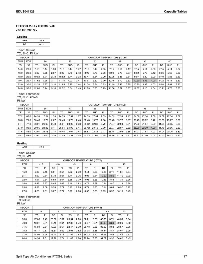
FTXS36LVJU + RXS36LVJU<60 Hz, 208 V>
Cooling
Heating
AFR 21.8
BF 0.27
Temp: CelsiusTC, SHC, PI: kW
INDOOR OUTDOOR TEMPERATURE (°CDB)
EWB EDB 20 25 30 32 35 40
°C °C TC SHC PI TC SHC PI TC SHC PI TC SHC PI TC SHC PI TC SHC PI
14.0 20.0 7.15 5.14 1.53 7.15 5.14 1.77 7.15 5.14 2.05 7.15 5.14 2.17 7.15 5.14 2.38 7.15 5.14 2.67
16.0 22.0 8.92 5.78 2.07 8.92 5.78 2.43 8.92 5.78 2.86 8.92 5.78 3.07 8.92 5.78 3.42 8.66 5.65 3.83
18.0 25.0 10.82 6.74 2.78 10.82 6.74 3.33 10.44 6.54 3.70 10.25 6.45 3.81 9.97 6.30 3.99 9.10 5.88 3.83
19.4 26.7 11.62 7.28 3.11 11.15 7.03 3.41 10.67 6.80 3.70 10.48 6.70 3.82 10.20 6.56 4.00 9.32 6.14 3.83
22.0 30.0 12.33 6.97 3.14 11.85 6.75 3.44 11.38 6.54 3.73 11.19 6.46 3.85 10.90 6.33 4.03 9.98 5.94 3.83
24.0 32.0 12.80 6.74 3.16 12.32 6.54 3.45 11.85 6.35 3.75 11.66 6.27 3.87 11.37 6.15 4.04 10.41 5.78 3.83
Temp: FahrenheitTC, SHC: kBtu/hPI: kW
INDOOR OUTDOOR TEMPERATURE (°FDB)
EWB EDB 68 77 86 90 95 104
°F °F TC SHC PI TC SHC PI TC SHC PI TC SHC PI TC SHC PI TC SHC PI
57.2 68.0 24.39 17.54 1.53 24.39 17.54 1.77 24.39 17.54 2.05 24.39 17.54 2.17 24.39 17.54 2.38 24.39 17.54 2.67
60.8 71.6 30.43 19.72 2.07 30.43 19.72 2.43 30.43 19.72 2.86 30.43 19.72 3.07 30.43 19.72 3.42 29.55 19.27 3.83
64.4 77.0 36.91 23.00 2.78 36.91 23.00 3.33 35.62 22.33 3.70 34.97 22.00 3.81 34.00 21.51 3.99 31.05 20.05 3.83
67.0 80.0 39.66 24.83 3.11 38.04 24.00 3.41 36.42 23.19 3.70 35.77 22.87 3.82 35.00 22.39 4.00 31.79 20.96 3.83
71.6 86.0 42.07 23.78 3.14 40.45 23.04 3.44 38.83 22.32 3.73 38.18 22.03 3.85 37.21 21.61 4.03 34.04 20.26 3.83
75.2 89.6 43.67 23.00 3.16 42.05 22.32 3.45 40.43 21.65 3.75 39.78 21.39 3.87 38.81 21.00 4.04 35.53 19.72 3.83
AFR 22.9
Temp: CelsiusTC, PI: kW
INDOOR OUTDOOR TEMPERATURE (°CWB)
EDB –15 –10 –5 0 6 10
°C TC PI TC PI TC PI TC PI TC PI TC PI
15.0 5.00 2.45 6.01 2.57 7.02 2.70 9.44 3.53 10.86 3.71 11.81 3.84
21.1 4.69 2.51 5.70 2.64 6.71 2.76 9.08 3.61 10.50 3.80 11.45 3.93
22.0 4.57 2.54 5.58 2.67 6.58 2.79 8.93 3.65 10.36 3.83 11.30 3.96
24.0 4.45 2.57 5.45 2.69 6.46 2.82 8.79 3.68 10.21 3.87 11.16 3.99
25.0 4.38 2.58 5.39 2.71 6.40 2.83 8.71 3.70 10.14 3.89 10.97 3.92
27.0 4.26 2.61 5.27 2.74 6.28 2.86 8.57 3.73 9.99 3.92 10.15 3.45
Temp: FahrenheitTC: kBtu/hPI: kW
INDOOR OUTDOOR TEMPERATURE (°FWB)
EDB 5 14 23 32 43 50
°F TC PI TC PI TC PI TC PI TC PI TC PI
59.0 17.06 2.45 20.50 2.57 23.94 2.70 32.21 3.53 37.06 3.71 40.30 3.84
70.0 16.01 2.51 19.45 2.64 22.89 2.76 30.97 3.61 36.00 3.80 39.06 3.93
71.6 15.59 2.54 19.03 2.67 22.47 2.79 30.48 3.65 35.33 3.83 38.57 3.96
75.2 15.17 2.57 18.61 2.69 22.05 2.82 29.98 3.68 34.84 3.87 38.07 3.99
77.0 14.96 2.58 18.40 2.71 21.84 2.83 29.73 3.70 34.59 3.89 37.44 3.92
80.6 14.54 2.61 17.98 2.74 21.42 2.86 29.24 3.73 34.09 3.92 34.62 3.45
Split Type Air Conditioners FTXS-L Series 17
Capacity Tables EDUS041129
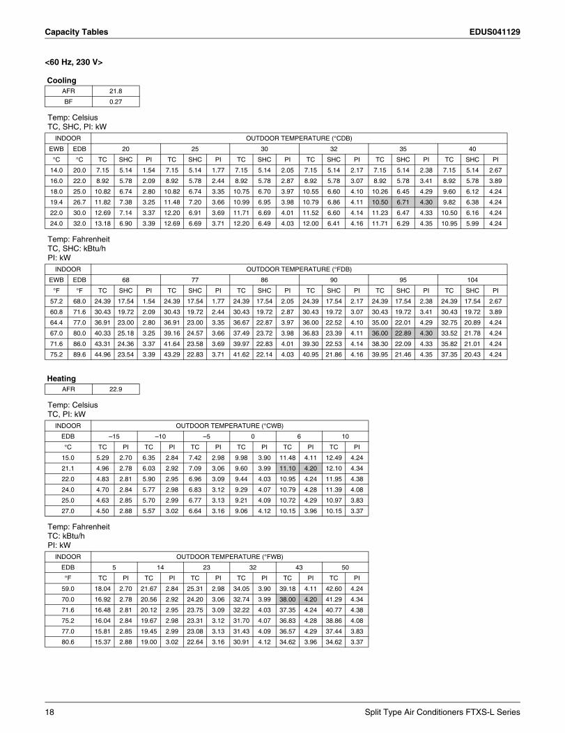
<60 Hz, 230 V>
Cooling
Heating
AFR 21.8
BF 0.27
Temp: CelsiusTC, SHC, PI: kW
INDOOR OUTDOOR TEMPERATURE (°CDB)
EWB EDB 20 25 30 32 35 40
°C °C TC SHC PI TC SHC PI TC SHC PI TC SHC PI TC SHC PI TC SHC PI
14.0 20.0 7.15 5.14 1.54 7.15 5.14 1.77 7.15 5.14 2.05 7.15 5.14 2.17 7.15 5.14 2.38 7.15 5.14 2.67
16.0 22.0 8.92 5.78 2.09 8.92 5.78 2.44 8.92 5.78 2.87 8.92 5.78 3.07 8.92 5.78 3.41 8.92 5.78 3.89
18.0 25.0 10.82 6.74 2.80 10.82 6.74 3.35 10.75 6.70 3.97 10.55 6.60 4.10 10.26 6.45 4.29 9.60 6.12 4.24
19.4 26.7 11.82 7.38 3.25 11.48 7.20 3.66 10.99 6.95 3.98 10.79 6.86 4.11 10.50 6.71 4.30 9.82 6.38 4.24
22.0 30.0 12.69 7.14 3.37 12.20 6.91 3.69 11.71 6.69 4.01 11.52 6.60 4.14 11.23 6.47 4.33 10.50 6.16 4.24
24.0 32.0 13.18 6.90 3.39 12.69 6.69 3.71 12.20 6.49 4.03 12.00 6.41 4.16 11.71 6.29 4.35 10.95 5.99 4.24
Temp: FahrenheitTC, SHC: kBtu/hPI: kW
INDOOR OUTDOOR TEMPERATURE (°FDB)
EWB EDB 68 77 86 90 95 104
°F °F TC SHC PI TC SHC PI TC SHC PI TC SHC PI TC SHC PI TC SHC PI
57.2 68.0 24.39 17.54 1.54 24.39 17.54 1.77 24.39 17.54 2.05 24.39 17.54 2.17 24.39 17.54 2.38 24.39 17.54 2.67
60.8 71.6 30.43 19.72 2.09 30.43 19.72 2.44 30.43 19.72 2.87 30.43 19.72 3.07 30.43 19.72 3.41 30.43 19.72 3.89
64.4 77.0 36.91 23.00 2.80 36.91 23.00 3.35 36.67 22.87 3.97 36.00 22.52 4.10 35.00 22.01 4.29 32.75 20.89 4.24
67.0 80.0 40.33 25.18 3.25 39.16 24.57 3.66 37.49 23.72 3.98 36.83 23.39 4.11 36.00 22.89 4.30 33.52 21.78 4.24
71.6 86.0 43.31 24.36 3.37 41.64 23.58 3.69 39.97 22.83 4.01 39.30 22.53 4.14 38.30 22.09 4.33 35.82 21.01 4.24
75.2 89.6 44.96 23.54 3.39 43.29 22.83 3.71 41.62 22.14 4.03 40.95 21.86 4.16 39.95 21.46 4.35 37.35 20.43 4.24
AFR 22.9
Temp: CelsiusTC, PI: kW
INDOOR OUTDOOR TEMPERATURE (°CWB)
EDB –15 –10 –5 0 6 10
°C TC PI TC PI TC PI TC PI TC PI TC PI
15.0 5.29 2.70 6.35 2.84 7.42 2.98 9.98 3.90 11.48 4.11 12.49 4.24
21.1 4.96 2.78 6.03 2.92 7.09 3.06 9.60 3.99 11.10 4.20 12.10 4.34
22.0 4.83 2.81 5.90 2.95 6.96 3.09 9.44 4.03 10.95 4.24 11.95 4.38
24.0 4.70 2.84 5.77 2.98 6.83 3.12 9.29 4.07 10.79 4.28 11.39 4.08
25.0 4.63 2.85 5.70 2.99 6.77 3.13 9.21 4.09 10.72 4.29 10.97 3.83
27.0 4.50 2.88 5.57 3.02 6.64 3.16 9.06 4.12 10.15 3.96 10.15 3.37
Temp: FahrenheitTC: kBtu/hPI: kW
INDOOR OUTDOOR TEMPERATURE (°FWB)
EDB 5 14 23 32 43 50
°F TC PI TC PI TC PI TC PI TC PI TC PI
59.0 18.04 2.70 21.67 2.84 25.31 2.98 34.05 3.90 39.18 4.11 42.60 4.24
70.0 16.92 2.78 20.56 2.92 24.20 3.06 32.74 3.99 38.00 4.20 41.29 4.34
71.6 16.48 2.81 20.12 2.95 23.75 3.09 32.22 4.03 37.35 4.24 40.77 4.38
75.2 16.04 2.84 19.67 2.98 23.31 3.12 31.70 4.07 36.83 4.28 38.86 4.08
77.0 15.81 2.85 19.45 2.99 23.08 3.13 31.43 4.09 36.57 4.29 37.44 3.83
80.6 15.37 2.88 19.00 3.02 22.64 3.16 30.91 4.12 34.62 3.96 34.62 3.37
18 Split Type Air Conditioners FTXS-L Series
EDUS041129 Capacity Tables
3D063319A
Symbols: Note:
AFR : Airflow rate (m3/min.) 1. Ratings shown are net capacities which include a deduction for indoor fan motor heat.
2. shows nominal (rated) capacities and power input.3. TC, PI and SHC must be calculated by interpolation using the figures in
the tables. (Figures out of the tables should not be used for calculation.)4. SHC values not included in the table must be calculated using
interpolation with values of direct proportion.5. Capacities are based on the following conditions.
Corresponding refrigerant piping length : 25 ftLevel difference : 0 ft
6. Cooling capacity at –15°CDB and 5°FDB.
BF : Bypass factor
EWB : Entering wet bulb temp. (°C) / (°F)
EDB : Entering dry bulb temp. (°C) / (°F)
TC : Total capacity (kW) / (kBtu/h)
SHC : Sensible heat capacity (kW) / (kBtu/h)
PI : Power input (kW)
Temp: CelsiusTC, SHC, PI: kW60 Hz, 208 - 230 V
INDOOR OUTDOOR
EWB EDB –15 (°CDB)
°C °C TC SHC PI
14.0 20.0 5.67 4.42 0.54
Temp: FahrenheitTC, SHC: kBtu/hPI: kW60 Hz, 208 - 230 V
INDOOR OUTDOOR
EWB EDB 5 (°FDB)
°F °F TC SHC PI
57.2 68.0 19.35 15.08 0.54
Split Type Air Conditioners FTXS-L Series 19
Capacity Tables EDUS041129
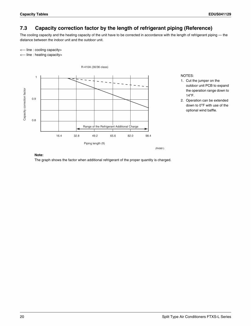
7.3 Capacity correction factor by the length of refrigerant piping (Reference)The cooling capacity and the heating capacity of the unit have to be corrected in accordance with the length of refrigerant piping — the distance between the indoor unit and the outdoor unit.
Note: The graph shows the factor when additional refrigerant of the proper quantity is charged.
<— line : cooling capacity><--- line : heating capacity>
Cap
acity
cor
rect
ion
fact
or
1
16.4 32.8 49.2 65.6 82.0 98.4
0.9
0.8
R-410A (30/36 class)
Piping length (ft)
(R4981)
Range of the Refrigerant Additional Charge
NOTES:1. Cut the jumper on the
outdoor unit PCB to expand the operation range down to 14°F.
2. Operation can be extended down to 0°F with use of the optional wind baffle.
20 Split Type Air Conditioners FTXS-L Series
EDUS041129 Operation Limit
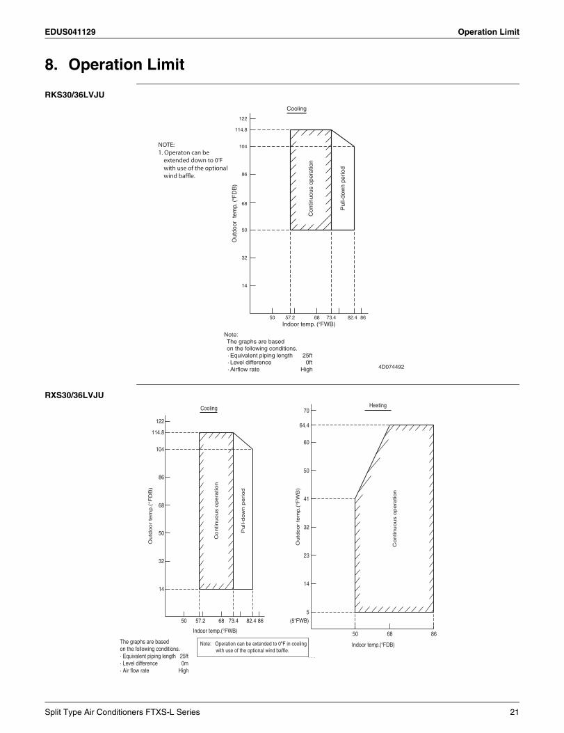
8. Operation Limit
RKS30/36LVJU
RXS30/36LVJU
Cooling
122
114.8
104
86
68
50
32
14
57.2 73.4 82.450 68 86
Out
door
tem
p. (
°FD
B)
Con
tinuo
us o
pera
tion
Pul
l-dow
n pe
riod
Indoor temp. (°FWB)
Note:
on the following conditions.The graphs are based
· Level difference 0ft· Airflow rate High
· Equivalent piping length 25ft
4D074492
NOTE:1. Operaton can be extended down to 0oF with use of the optional wind baffle.
The graphs are basedon the following conditions.
Notes:
· Equivalent piping length0ft
High
25ft
· Airflow rate· Level difference
64.4
Heating70
60
41
32
23
14
5
50 8668
50
Continuous o
pera
tion
Outd
oor
tem
p.(
°FW
B)
Indoor temp.(°FDB)
(5°FWB)
Cooling
122
114.8
104
86
68
50
Outd
oor
tem
p.(
°FD
B)
Pull-
dow
n p
eri
od
Continuous o
pera
tion
32
14
57.2 73.4 82.468 8650
Indoor temp.(°FWB)
The graphs are basedon the following conditions.· Equivalent piping length 25ft· Level difference 0m· Air flow rate High 4D071134
Note: Operation can be extended to 0ºF in cooling with use of the optional wind baffle.
Split Type Air Conditioners FTXS-L Series 21
Sound Level EDUS041129
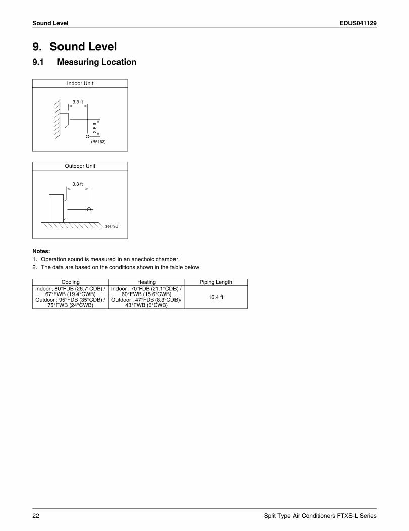
9. Sound Level9.1 Measuring Location
Notes:1. Operation sound is measured in an anechoic chamber.2. The data are based on the conditions shown in the table below.
Indoor Unit
Outdoor Unit
Cooling Heating Piping LengthIndoor ; 80°FDB (26.7°CDB) /
67°FWB (19.4°CWB)Outdoor ; 95°FDB (35°CDB) /
75°FWB (24°CWB)
Indoor ; 70°FDB (21.1°CDB) / 60°FWB (15.6°CWB)
Outdoor ; 47°FDB (8.3°CDB)/ 43°FWB (6°CWB)
16.4 ft
3.3 ft
2.6
ft
(R5162)
3.3 ft
(R4796)
22 Split Type Air Conditioners FTXS-L Series
EDUS041129 Sound Level
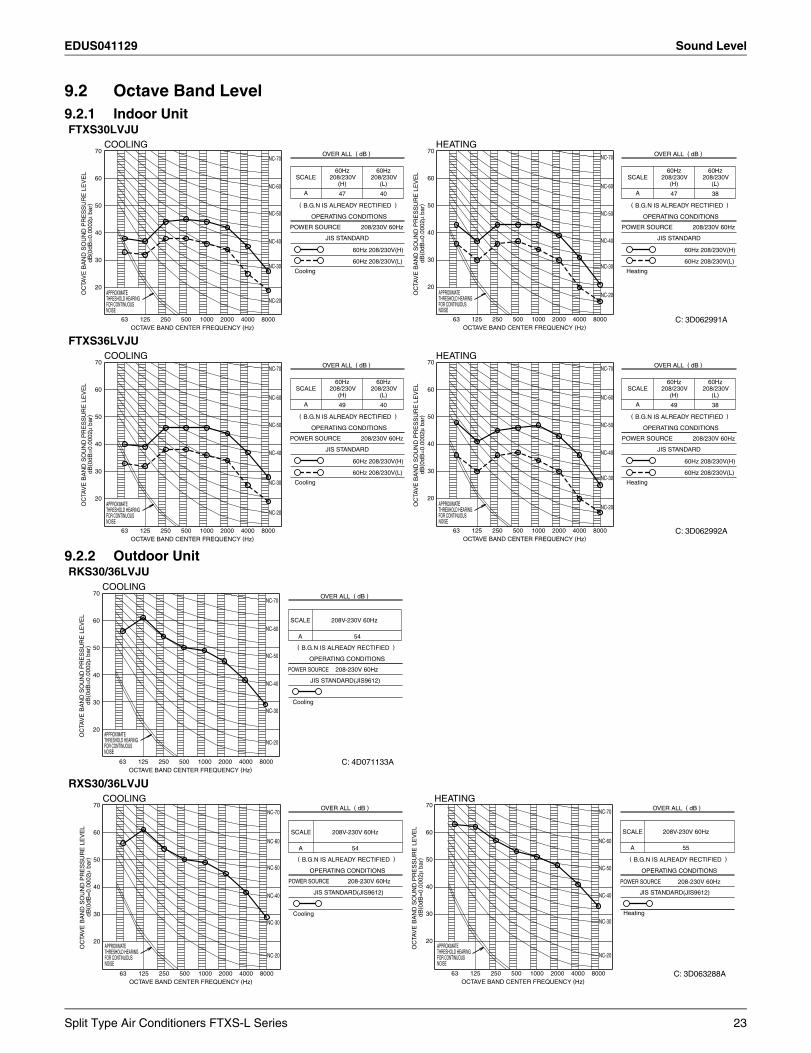
9.2 Octave Band Level9.2.1 Indoor Unit
9.2.2 Outdoor Unit
FTXS30LVJU
FTXS36LVJU
RKS30/36LVJU
RXS30/36LVJU
COOLING
NC-40
NC-30
NC-50
NC-60
NC-70
NC-20
60Hz 208/230V(H)
208/230V 60Hz
HEATING
NC-40
NC-30
NC-50
NC-60
NC-70
NC-20
Cooling
60Hz 208/230V(L)
POWER SOURCE
JIS STANDARD
OPERATING CONDITIONS
OC
TAV
E B
AN
D S
OU
ND
PR
ES
SU
RE
LE
VE
LdB
( 0dB
=0.
0002
μ ba
r)
70
60
20
30
50
40
THRESHOLD HEARINGAPPROXIMATE
FOR CONTINUOUSNOISE
63 125OCTAVE BAND CENTER FREQUENCY (Hz)
250 500 1000 2000 4000 8000
OVER ALL ( dB )
( B.G.N IS ALREADY RECTIFIED )
70
60
20
30
50
40
63OCTAVE BAND CENTER FREQUENCY (Hz)
125 250 500 1000 2000 4000 8000
OC
TAV
E B
AN
D S
OU
ND
PR
ES
SU
RE
LE
VE
LdB
( 0dB
=0.
0002
μ ba
r)
THRESHOLD HEARINGAPPROXIMATE
FOR CONTINUOUSNOISE
SCALE60Hz
208/230V(H)
60Hz208/230V
(L)
A 47 40
60Hz 208/230V(H)
208/230V 60Hz
Heating
60Hz 208/230V(L)
POWER SOURCE
JIS STANDARD
OPERATING CONDITIONS
OVER ALL ( dB )
( B.G.N IS ALREADY RECTIFIED )
SCALE60Hz
208/230V(H)
60Hz208/230V
(L)
A 47 38
C: 3D062991A
COOLING
NC-40
NC-30
NC-50
NC-60
NC-70
NC-20
HEATING
NC-40
NC-30
NC-50
NC-60
NC-70
NC-20OC
TAV
E B
AN
D S
OU
ND
PR
ES
SU
RE
LE
VE
LdB
( 0dB
=0.
0002
μ ba
r)
70
60
20
30
50
40
THRESHOLD HEARINGAPPROXIMATE
FOR CONTINUOUSNOISE
63 125OCTAVE BAND CENTER FREQUENCY (Hz)
250 500 1000 2000 4000 8000
70
60
20
30
50
40
63OCTAVE BAND CENTER FREQUENCY (Hz)
125 250 500 1000 2000 4000 8000
OC
TAV
E B
AN
D S
OU
ND
PR
ES
SU
RE
LE
VE
LdB
( 0dB
=0.
0002
μ ba
r)
THRESHOLD HEARINGAPPROXIMATE
FOR CONTINUOUSNOISE
60Hz 208/230V(H)
208/230V 60Hz
Cooling
60Hz 208/230V(L)
POWER SOURCE
JIS STANDARD
OPERATING CONDITIONS
OVER ALL ( dB )
( B.G.N IS ALREADY RECTIFIED )
SCALE60Hz
208/230V(H)
60Hz208/230V
(L)
A 49 40
60Hz 208/230V(H)
208/230V 60Hz
Heating
60Hz 208/230V(L)
POWER SOURCE
JIS STANDARD
OPERATING CONDITIONS
OVER ALL ( dB )
( B.G.N IS ALREADY RECTIFIED )
SCALE60Hz
208/230V(H)
60Hz208/230V
(L)
A 49 38
C: 3D062992A
POWER SOURCE
JIS STANDARD(JIS9612)
OPERATING CONDITIONS
OC
TAV
E B
AN
D S
OU
ND
PR
ES
SU
RE
LE
VE
LdB
( 0dB
=0.
0002
μ ba
r)
70
60
20
30
50
40
THRESHOLD HEARINGAPPROXIMATE
FOR CONTINUOUSNOISE
63 125OCTAVE BAND CENTER FREQUENCY (Hz)
250 500 1000 2000 4000 8000
OVER ALL ( dB )
SCALE
A
( B.G.N IS ALREADY RECTIFIED )
COOLING
208V-230V 60Hz
54
208-230V 60Hz
NC-60
NC-70
NC-50
NC-40
NC-30
NC-20
Cooling
C: 4D071133A
208-230V 60Hz
NC-50
208V-230V 60Hz
NC-40
54
NC-20
NC-50
NC-30
NC-60
NC-70
NC-30
NC-40
NC-60
NC-70
NC-20
POWER SOURCE
JIS STANDARD(JIS9612)
OPERATING CONDITIONS
OC
TAV
E B
AN
D S
OU
ND
PR
ES
SU
RE
LE
VE
LdB
( 0dB
=0.
0002
μ ba
r)
70
60
20
30
50
40
THRESHOLD HEARINGAPPROXIMATE
FOR CONTINUOUSNOISE
63 125OCTAVE BAND CENTER FREQUENCY (Hz)
250 500 1000 2000 4000 8000
OVER ALL ( dB )
SCALE
A
( B.G.N IS ALREADY RECTIFIED )
70
60
20
30
50
40
63OCTAVE BAND CENTER FREQUENCY (Hz)
125 250 500 1000 2000 4000 8000
OC
TAV
E B
AN
D S
OU
ND
PR
ES
SU
RE
LE
VE
LdB
( 0dB
=0.
0002
μ ba
r)
THRESHOLD HEARINGAPPROXIMATE
FOR CONTINUOUSNOISE
POWER SOURCE
JIS STANDARD(JIS9612)
OPERATING CONDITIONS
OVER ALL ( dB )
SCALE
A
( B.G.N IS ALREADY RECTIFIED )
COOLING HEATING
208V-230V 60Hz
55
208-230V 60Hz
Cooling Heating
C: 3D063288A
Split Type Air Conditioners FTXS-L Series 23
Electric Characteristics EDUS041129
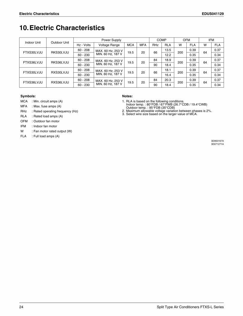
10.Electric Characteristics
3D063167A3D071271A
Indoor Unit Outdoor UnitPower Supply COMP OFM IFM
Hz - Volts Voltage Range MCA MFA RHz RLA W FLA W FLA
FTXS30LVJU RKS30LVJU60 - 208 MAX. 60 Hz, 253 V
MIN. 60 Hz, 187 V 19.5 20 6613.5
2000.39
640.37
60 - 230 12.2 0.35 0.34
FTXS36LVJU RKS36LVJU60 - 208 MAX. 60 Hz, 253 V
MIN. 60 Hz, 187 V 19.5 2084 18.9
2000.39
640.37
60 - 230 90 18.4 0.35 0.34
FTXS30LVJU RXS30LVJU60 - 208 MAX. 60 Hz, 253 V
MIN. 60 Hz, 187 V 19.5 20 6618.1
2000.39
640.37
60 - 230 16.4 0.35 0.34
FTXS36LVJU RXS36LVJU60 - 208 MAX. 60 Hz, 253 V
MIN. 60 Hz, 187 V 19.5 2084 20.3
2000.39
640.37
60 - 230 90 18.4 0.35 0.34
Symbols: Notes:
MCA : Min. circuit amps (A) 1. RLA is based on the following conditions.Indoor temp. : 80°FDB / 67°FWB (26.7°CDB / 19.4°CWB)Outdoor temp. : 95°FDB (35°CDB)
2. Maximum allowable voltage variation between phases is 2%.3. Select wire size based on the larger value of MCA.
MFA : Max. fuse amps (A)
RHz : Rated operating frequency (Hz)
RLA : Rated load amps (A)
OFM : Outdoor fan motor
IFM : Indoor fan motor
W : Fan motor rated output (W)
FLA : Full load amps (A)
24 Split Type Air Conditioners FTXS-L Series
EDUS041129 Installation Manual
11. Installation Manual11.1 Indoor Unit Safety Considerations
Read these SAFETY CONSIDERATIONS for Installation carefully before installing an air conditioner or heat pump. After completing the installation, make sure that the unit operates properly during the startup operation.Instruct the customer on how to operate and maintain the unit. Inform customers that they should store this Installation Manual with the Operation Manual for future reference.Always use a licensed installer or contractor to install this product. Improper installation can result in water or refrigerant leakage, electrical shock, fire, or explosion.Meanings of DANGER, WARNING, CAUTION, and NOTE Symbols:
DANGER .............. Indicates an imminently hazardous situation which, if not avoided, will result in death or serious injury.
WARNING ............ Indicates a potentially hazardous situation which, if not avoided, could result in death or serious injury.
CAUTION ............. Indicates a potentially hazardous situation which, if not avoided, may result in minor or moderate injury. It may also be used to alert against unsafe practices.
NOTE .................. Indicates situations that may result in equipment or property-damage accidents only.
• Refrigerant gas is heavier than air and replaces oxygen. A massive leak can lead to oxygen depletion, especially in basements, and an asphyxiation hazard could occur leading to serious injury or death.
• Do not ground units to water pipes, gas pipes, telephone wires, or lightning rods as incomplete grounding can cause a severe shock hazard resulting in severe injury or death. Additionally, grounding to gas pipes could cause a gas leak and potential explosion causing severe injury or death.
• If refrigerant gas leaks during installation, ventilate the area immediately. Refrigerant gas may produce toxic gas if it comes into contact with fire. Exposure to this gas could cause severe injury or death.
• After completing the installation work, check that the refrigerant gas does not leak throughout the system.
• Do not install unit in an area where flammable materials are present due to risk of explosions that can cause serious injury or death.
• Safely dispose all packing and transportation materials in accordance with federal/state/local laws or ordinances. Packing materials such as nails and other metal or wood parts, including plastic packing materials used for transportation may cause injuries or death by suffocation.
• Only qualified personnel must carry out the installation work. Installation must be done in accordance with this
installation manual. Improper installation may result in water leakage, electric shock, or fire.
• When installing the unit in a small room, take measures to keep the refrigerant concentration from exceeding allowable safety limits. Excessive refrigerant leaks, in the event of an accident in a closed ambient space, can lead to oxygen deficiency.
• Use only specified accessories and parts for installation work. Failure to use specified parts may result in water leakage, electric shocks, fire, or the unit falling.
• Install the air conditioner or heat pump on a foundation strong enough that it can withstand the weight of the unit. A foundation of insufficient strength may result in the unit falling and causing injuries.
• Take into account strong winds, typhoons, or earthquakes when installing. Improper installation may result in the unit falling and causing accidents.
• Make sure that a separate power supply circuit is provided for this unit and that all electrical work is carried out by qualified personnel according to local. state, and national regulations. An insufficient power supply capacity or improper electrical construction may lead to electric shocks or fire.
• Make sure that all wiring is secured, that specified wires are used, and that no external forces act on the terminal connections or wires. Improper connections or installation may result in fire.
• When wiring, position the wires so that the terminal box lid can be securely fastened. Improper positioning of the terminal box lid may result in electric shocks, fire, or the terminals overheating.
• Before touching electrical parts, turn off the unit.
• Securely fasten the outside unit terminal cover (panel). If the terminal cover/panel is not installed properly, dust or water may enter the outside unit causing fire or electric shock.
• When installing or relocating the system, keep the refrigerant circuit free from substances other than the specified refrigerant (R-410A) such as air. Any presence of air or other foreign substance in the refrigerant circuit can cause an abnormal pressure rise or rupture, resulting in injury.
• Do not change the setting of the protection devices. If the pressure switch, thermal switch, or other protection device is shorted and operated forcibly, or parts other than those specified by Daikin are used, fire or explosion may occur.
Split Type Air Conditioners FTXS-L Series 25
Installation Manual EDUS041129
• Do not touch the switch with wet fingers. Touching a switch with wet fingers can cause electric shock.
• Do not allow children to play on or around the unit to prevent injury.
• The heat exchanger fins are sharp enough to cut. To avoid injury wear gloves or cover the fins while working around them.
• Do not touch the refrigerant pipes during and immediately after operation as the refrigerant pipes may be hot or cold, depending on the condition of the refrigerant flowing through the refrigerant piping, compressor, and other refrigerant cycle parts. Your hands may suffer burns or frostbite if you touch the refrigerant pipes. To avoid injury, give the pipes time to return to normal temperature or, if you must touch them, be sure to wear proper gloves.
• Install drain piping to proper drainage. Improper drain piping may result in water leakage and property damage.
• Insulate piping to prevent condensation.
• Be careful when transporting the product.
• Do not turn off the power immediately after stopping operation. Always wait for at least 5 minutes before turning off the power. Otherwise, water leakage may occur.
• Do not use a charging cylinder. Using a charging cylinder may cause the refrigerant to deteriorate.
• Refrigerant R-410A in the system must be kept clean, dry, and tight.
(a) Clean and Dry -- Foreign materials (including mineral oils such as SUNISO oil or moisture) should be prevented from getting into the system.
(b) Tight -- R-410A does not contain any chlorine, does not destroy the ozone layer, and does not reduce the earth’s protection again harmful ultraviolet radiation. R-410A can contribute to the greenhouse effect if it is released. Therefore take proper measures to check for the tightness of the refrigerant piping installation. Read the chapter Refrigerant Piping and follow the procedures.
• Since R-410A is a blend, the required additional refrigerant must be charged in its liquid state. If the refrigerant is charged in a state of gas, its composition can change and the system will not work properly.
• The indoor unit is for R-410A. See the catalog for indoor models that can be connected. Normal operation is not possible when connected to other units.
• Remote controller (wireless kit) transmitting distance can be shorter than expected in rooms with electronic fluorescent lamps (inverter or rapid start types). Install the indoor unit far away from fluorescent lamps as much as possible.
• Indoor units are for indoor installation only. Outdoor units can be installed either outdoors or indoors. This unit is for indoor use.
• Do not install the air conditioner or heat pump in the following locations:(a) Where a mineral oil mist or oil spray or vapor is
produced, for example, in a kitchen. Plastic parts may deteriorate and fall off or result in water leakage.
(b) Where corrosive gas, such as sulfurous acid gas, is produced.Corroding copper pipes or soldered parts may result in refrigerant leakage.
(c) Near machinery emitting electromagnetic waves. Electromagnetic waves may disturb the operation of the control system and cause the unit to malfunction.
(d) Where flammable gas may leak, where there is carbon fiber, or ignitable dust suspension in the air, or where volatile flammables such as thinner or gasoline are handled. Operating the unit in such conditions can cause a fire.
• Take adequate measures to prevent the outside unit from being used as a shelter by small animals. Small animals making contact with electrical parts can cause malfunctions, smoke, or fire. Instruct the customer to keep the area around the unit clean.
• Install the power supply and control wires for the indoor and outdoor units at least 3.5 feet away from televisions or radios to prevent image interference or noise. Depending on the radio waves, a distance of 3.5 feet may not be sufficient to eliminate the noise.
• Dismantling the unit, treatment of the refrigerant, oil and additional parts must be done in accordance with the relevant local, state, and national regulations.
• Do not use the following tools that are used with conventional refrigerants: gauge manifold, charge hose, gas leak detector, reverse flow check valve, refrigerant charge base, vacuum gauge, or refrigerant recovery equipment.
• If the conventional refrigerant and refrigerator oil are mixed in R-410A, the refrigerant may deteriorate.
• This air conditioner or heat pump is an appliance that should not be accessible to the general public.
• As design pressure is 478 psi, the wall thickness of field-installed pipes should be selected in accordance with the relevant local, state, and national regulations.
26 Split Type Air Conditioners FTXS-L Series
EDUS041129 Installation Manual
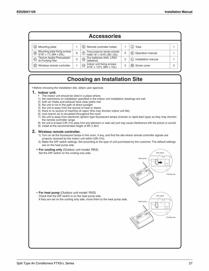
1. Indoor unit.• The indoor unit should be sited in a place where:1) the restrictions on installation specified in the indoor unit installation drawings are met 2) both air intake and exhaust have clear paths met 3) the unit is not in the path of direct sunlight 4) the unit is away from the source of heat or steam 5) there is no source of machine oil vapor (this may shorten indoor unit life)
6) cool (warm) air is circulated throughout the room 7) the unit is away from electronic ignition type fluorescent lamps (inverter or rapid start type) as they may shorten
the remote controller range 8) the unit is at least 3.5ft (1m) away from any television or radio set (unit may cause interference with the picture or sound) 9) install at the recommended height of 6ft (1.8m)
2. Wireless remote controller.1) Turn on all the fluorescent lamps in the room, if any, and find the site where remote controller signals are
properly received by the indoor unit within 23ft (7m).2) Make the DIP switch settings. Set according to the type of unit purchased by the customer. The default settings
are on the heat pump side.
• For cooling only (Outdoor unit model: RKS) Set the DIP switch on the cooling only side.
• For heat pump (Outdoor unit model: RXS) Check that the DIP switch is on the heat pump side.If they are set on the cooling only side, move them to the heat pump side.
• Before choosing the installation site, obtain user approval.
A
B
C
D
E
F
G
H
J
K
M
1
19
13
1
2
33
Mounting plate
Titanium Apatite PhotocatalyticAir-Purifying Filter
Wireless remote controller
Remote controller holder
Dry batteries AAA. LR03 (alkaline)
Fixing screws for remote controller holder 1/8” × 13/16”L (M3 × 20L) Operation manual
Screw cover
L Installation manual
Mounting plate fixing screws 3/16” × 1”L (M4 × 25L)
Tube 1
Indoor unit fixing screws3/16” × 1/2”L (M4 × 12L)
Accessories
Choosing an Installation Site
DIP switch
Heat pump
Cooling only
DIP switch
Heat pump
Cooling only
2
1
Split Type Air Conditioners FTXS-L Series 27
Installation Manual EDUS041129
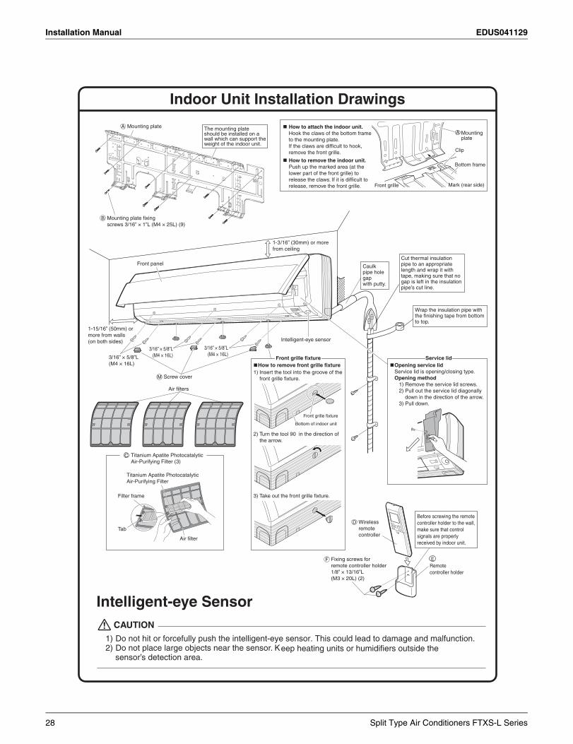
Indoor Unit Installation Drawings
Intelligent-eye Sensor
1) Do not hit or forcefully push the intelligent-eye sensor. This could lead to damage and malfunction. 2) Do not place large objects near the sensor. Keep heating units or humidifiers outside the
sensor’s detection area.
CAUTION
1) Insert the tool into the groove of the front grille fixture.
How to remove front grille fixture
2) Turn the tool 90 in the direction of the arrow.
3) Take out the front grille fixture.
1-3/16” (30mm) or more from ceiling
Wrap the insulation pipe with the finishing tape from bottom to top.
Cut thermal insulation pipe to an appropriate length and wrap it with tape, making sure that no gap is left in the insulation pipe’s cut line.
Caulk pipe hole gap with putty.
C Titanium Apatite Photocatalytic Air-Purifying Filter (3)
How to attach the indoor unit.Hook the claws of the bottom frame to the mounting plate. If the claws are difficult to hook, remove the front grille.
How to remove the indoor unit.Push up the marked area (at the lower part of the front grille) to release the claws. If it is difficult to release, remove the front grille.
Opening service lidService lid is opening/closing type.Opening method
1) Remove the service lid screws.2) Pull out the service lid diagonally
down in the direction of the arrow.3) Pull down.
Air filters
Front grille
A Mountingplate
Clip
Bottom frame
Mark (rear side)
A Mounting plate
Mounting plate fixing screws 3/16” × 1”L (M4 × 25L) (9)
B
The mounting plate should be installed on a wall which can support the weight of the indoor unit.
Intelligent-eye sensor
1-15/16” (50mm) or more from walls (on both sides)
Front panel
3/16” × 5/8”L(M4 × 16L)3/16” × 5/8”L
(M4 × 16L)
3/16” × 5/8”L(M4 × 16L)
Service lidFront grille fixture
Wireless remote controller
D
E Remote controller holder
Before screwing the remote controller holder to the wall, make sure that control signals are properly received by indoor unit.
Fixing screws for remote controller holder 1/8” × 13/16”L (M3 × 20L) (2)
F
Titanium Apatite Photocatalytic Air-Purifying Filter
Filter frame
Air filter
Tab
Bottom of indoor unit
Front grille fixture
Screw coverM
28 Split Type Air Conditioners FTXS-L Series
EDUS041129 Installation Manual
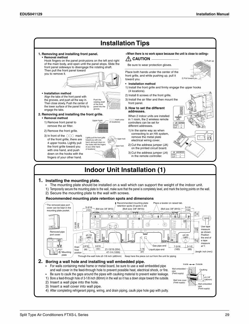
1. Installing the mounting plate.• The mounting plate should be installed on a wall which can support the weight of the indoor unit.1) Temporarily secure the mounting plate to the wall, make sure that the panel is completely level, and mark the boring points on the wall.2) Secure the mounting plate to the wall with screws.
Recommended mounting plate retention spots and dimensions
Indoor Unit Installation (1)
Installation Tips
1. Removing and installing front panel.• Removal method
Hook fingers on the panel protrusions on the left and right of the main body, and open until the panel stops. Slide the front panel sideways to disengage the rotating shaft. Then pull the front panel toward you to remove it.
• Installation methodAlign the tabs of the front panel with the grooves, and push all the way in. Then close slowly. Push the center of the lower surface of the panel firmly to engage the tabs.
2. Removing and installing the front grille.• Removal method
1) Remove front panel to remove the air filter.
2) Remove the front grille.
3) In front of the mark of the front grille, there are 4 upper hooks. Lightly pull the front grille toward you with one hand, and push down on the hooks with the fingers of your other hand.
<When there is no work space because the unit is close to ceiling>
Be sure to wear protection gloves.
Place both hands under the center of the front grille, and while pushing up, pull it toward you.
• Installation method1) Install the front grille and firmly engage the upper hooks
(4 locations).2) Install 6 screws of the front grille.3) Install the air filter and then mount the
front panel.
3. How to set the different addresses.When 2 indoor units are installed in 1 room, the 2 wireless remote controllers can be set for different addresses.
1) In the same way as when connecting to an HA system, remove the metal plate electrical wiring cover.
2) Cut the address jumper (JA) on the printed circuit board.
3) Cut the address jumper (J4) in the remote controller.
CAUTION
2. Boring a wall hole and installing wall embedded pipe.• For walls containing metal frame or metal board, be sure to use a wall embedded pipe
and wall cover in the feed-through hole to prevent possible heat, electrical shock, or fire.• Be sure to caulk the gaps around the pipes with caulking material to prevent water leakage.1) Bore a feed-through hole of 3-1/8 inch (80mm) in the wall so it has a down slope toward the outside.2) Insert a wall pipe into the hole.3) Insert a wall cover into wall pipe.4) After completing refrigerant piping, wiring, and drain piping, caulk pipe hole gap with putty.
φ3-1/8(φ80)
7-1/
2(1
90)
2-1/16
(53)
5-1/4(134)
5-3/16(131)
1-3/
4 (4
5)
1-3/
4(4
5)
13-3
/8(3
40)
2-9/16(65)
φ3-1/8(φ80)
6-5/16(161)
7-3/16(183)
3-1/2(89)
47-1/4 (1200)1-7/8(47)
21-13/16 (554)(length: inch (mm))
Use tape measure as shown.Position the end of a tape measure at ∇.Gas pipe end
Liquid pipe end
Keep here the piece cut out from the unit for pipingThrough-the-wall hole φ3-1/8 inch (φ80mm)
Drain hose position
Removed pipe port cover
A Mounting plate
* The removed pipe port cover can be kept in the mounting plate pocket.
Recommended mounting plate retention spots (9 spots in all)
(Bolt size: 3/8” (M10)) (Bolt size: 3/8” (M10)) (Bolt size: 3/8” (M10))
Place a leveler on raised tab.
mark area (4 locations)
Upper hook
Lightly pull the front grille toward you with one hand, and push down on the hooks with the fingers of your other hand.(4 locations)
Pushdown.
Upper hook
Upper hook
1) Push up.
2) Pull toward you.
Push the rotating shaft of the front panel into the groove.
ADDR
ESS
JA
ADDRESSJAEXIST 1CUT 2
ADDRESSJ4EXIST CUT
12
J4
Inside Outside
CaulkingWall embedded pipe (Field supply)
Wall hole cover(Field supply)
Wall embedded pipe (Field supply)
φ3-1/8”(φ80mm)
Split Type Air Conditioners FTXS-L Series 29
Installation Manual EDUS041129
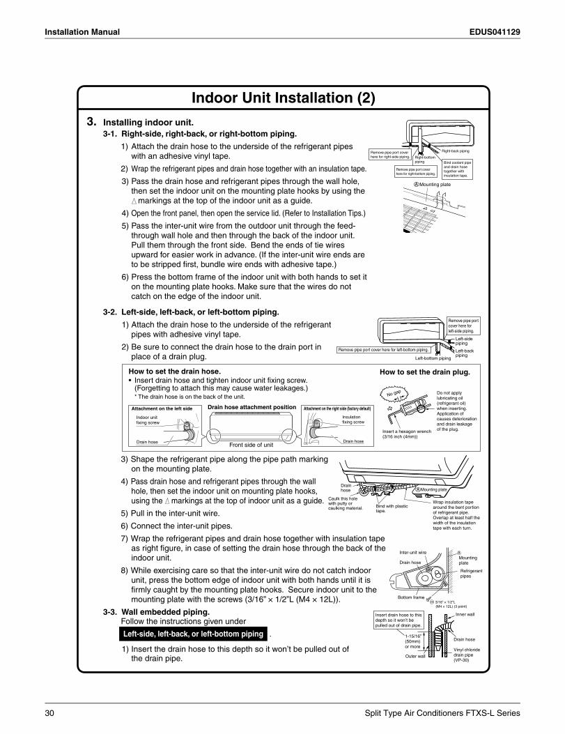
Indoor Unit Installation (2)
3-2. Left-side, left-back, or left-bottom piping.
1) Attach the drain hose to the underside of the refrigerant pipes with adhesive vinyl tape.
2) Be sure to connect the drain hose to the drain port in place of a drain plug.
3) Shape the refrigerant pipe along the pipe path marking on the mounting plate.
4) Pass drain hose and refrigerant pipes through the wall hole, then set the indoor unit on mounting plate hooks, using the markings at the top of indoor unit as a guide.
5) Pull in the inter-unit wire.
6) Connect the inter-unit pipes.
7) Wrap the refrigerant pipes and drain hose together with insulation tape as right figure, in case of setting the drain hose through the back of the indoor unit.
8) While exercising care so that the inter-unit wire do not catch indoor unit, press the bottom edge of indoor unit with both hands until it is firmly caught by the mounting plate hooks. Secure indoor unit to the mounting plate with the screws (3/16” × 1/2”L (M4 × 12L)).
3. Installing indoor unit.3-1. Right-side, right-back, or right-bottom piping.
1) Attach the drain hose to the underside of the refrigerant pipes with an adhesive vinyl tape.
2) Wrap the refrigerant pipes and drain hose together with an insulation tape.
3) Pass the drain hose and refrigerant pipes through the wall hole, then set the indoor unit on the mounting plate hooks by using the markings at the top of the indoor unit as a guide.
4) Open the front panel, then open the service lid. (Refer to Installation Tips.)
5) Pass the inter-unit wire from the outdoor unit through the feed-through wall hole and then through the back of the indoor unit. Pull them through the front side. Bend the ends of tie wires upward for easier work in advance. (If the inter-unit wire ends are to be stripped first, bundle wire ends with adhesive tape.)
6) Press the bottom frame of the indoor unit with both hands to set it on the mounting plate hooks. Make sure that the wires do not catch on the edge of the indoor unit.
3-3. Wall embedded piping.Follow the instructions given under
1) Insert the drain hose to this depth so it won’t be pulled out of the drain pipe.
Left-side, left-back, or left-bottom piping .
Remove pipe port cover here for left-bottom piping.
Remove pipe port cover here for left-side piping.
Left-bottom piping
Left-side piping
Left-back piping
How to set the drain hose.• Insert drain hose and tighten indoor unit fixing screw.
(Forgetting to attach this may cause water leakages.)* The drain hose is on the back of the unit.
How to set the drain plug.
Front side of unit
Drain hose attachment positionAttachment on the left side
Drain hose
Indoor unit fixing screw
Attachment on the right side (factory default)
Drain hose
Insulation fixing screw
No gap Do not apply lubricating oil (refrigerant oil) when inserting.Application of causes deterioration and drain leakage of the plug.Insert a hexagon wrench
(3/16 inch (4mm))
Wrap insulation tape around the bent portion of refrigerant pipe. Overlap at least half the width of the insulation tape with each turn.
Drain hose
Caulk this hole with putty or caulking material. Bind with plastic
tape.
A Mounting plate
Refrigerantpipes
Drain hose
Bottom frameH 3/16” × 1/2”L (M4 × 12L) (3 point)
Inter-unit wireMountingplate
A
Inner wall
Vinyl chloride drain pipe (VP-30)
Drain hose1-15/16” (50mm) or more
Insert drain hose to this depth so it won’t be pulled out of drain pipe.
Outer wall
Right-bottom piping
Right-back piping
Bind coolant pipe and drain hose together with insulation tape.
Remove pipe port cover here for right-side piping.
Remove pipe port cover here for right-bottom piping.
Mounting plateA
30 Split Type Air Conditioners FTXS-L Series
EDUS041129 Installation Manual
Split Type Air Conditioners FTXS-L Series 31
Installation Manual EDUS041129
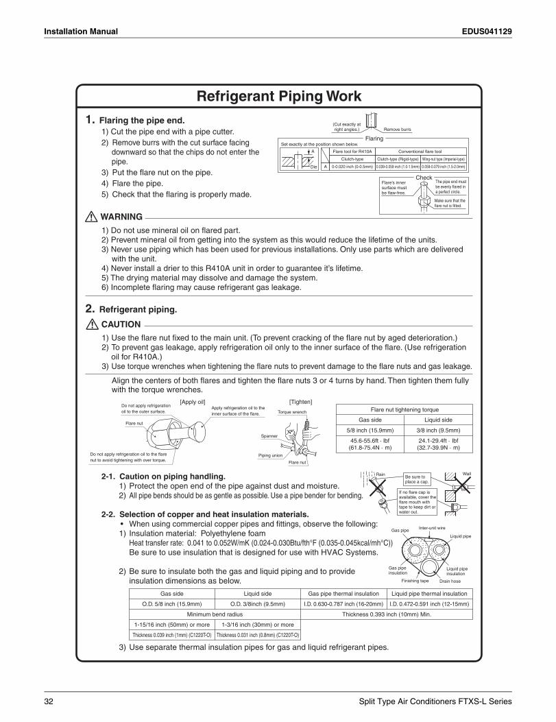
Align the centers of both flares and tighten the flare nuts 3 or 4 turns by hand. Then tighten them fully with the torque wrenches.
Refrigerant Piping Work
2. Refrigerant piping.
2-1. Caution on piping handling.1) Protect the open end of the pipe against dust and moisture.2) All pipe bends should be as gentle as possible. Use a pipe bender for bending.
2-2. Selection of copper and heat insulation materials.• When using commercial copper pipes and fittings, observe the following:1) Insulation material: Polyethylene foam
Heat transfer rate: 0.041 to 0.052W/mK (0.024-0.030Btu/fth°F (0.035-0.045kcal/mh°C))Be sure to use insulation that is designed for use with HVAC Systems.
2) Be sure to insulate both the gas and liquid piping and to provide insulation dimensions as below.
3) Use separate thermal insulation pipes for gas and liquid refrigerant pipes.
Flare nut tightening torque
Gas side Liquid side
45.6-55.6ft · lbf(61.8-75.4N · m)
24.1-29.4ft · lbf(32.7-39.9N · m)
5/8 inch (15.9mm) 3/8 inch (9.5mm)
1) Use the flare nut fixed to the main unit. (To prevent cracking of the flare nut by aged deterioration.)2) To prevent gas leakage, apply refrigeration oil only to the inner surface of the flare. (Use refrigeration
oil for R410A.)3) Use torque wrenches when tightening the flare nuts to prevent damage to the flare nuts and gas leakage.
CAUTION
1. Flaring the pipe end.1) Cut the pipe end with a pipe cutter.2) Remove burrs with the cut surface facing
downward so that the chips do not enter the pipe.
3) Put the flare nut on the pipe.4) Flare the pipe.5) Check that the flaring is properly made.
1) Do not use mineral oil on flared part.2) Prevent mineral oil from getting into the system as this would reduce the lifetime of the units.3) Never use piping which has been used for previous installations. Only use parts which are delivered
with the unit.4) Never install a drier to this R410A unit in order to guarantee it’s lifetime.5) The drying material may dissolve and damage the system.6) Incomplete flaring may cause refrigerant gas leakage.
WARNING
Gas pipe thermal insulationLiquid sideGas side Liquid pipe thermal insulation
I.D. 0.630-0.787 inch (16-20mm)O.D. 3/8inch (9.5mm)O.D. 5/8 inch (15.9mm) I.D. 0.472-0.591 inch (12-15mm)
Minimum bend radius Thickness 0.393 inch (10mm) Min.
1-3/16 inch (30mm) or more1-15/16 inch (50mm) or more
Thickness 0.031 inch (0.8mm) (C1220T-O)Thickness 0.039 inch (1mm) (C1220T-O)
Wall
If no flare cap is available, cover the flare mouth with tape to keep dirt or water out.
Be sure to place a cap.
Rain
Gas pipeLiquid pipe
Gas pipe insulation
Liquid pipe insulation
Finishing tape Drain hose
Inter-unit wire
Torque wrench
Piping union
Flare nut
Do not apply refrigeration oil to the outer surface.
Flare nut
Apply refrigeration oil to the inner surface of the flare.
Do not apply refrigeration oil to the flare nut to avoid tightening with over torque.
Spanner
[Apply oil] [Tighten]
(Cut exactly at right angles.) Remove burrs
Set exactly at the position shown below.
A
Flaring
Die A 0-0.020 inch (0-0.5mm)
Clutch-type
Flare tool for R410A
0.039-0.059 inch (1.0-1.5mm)
Clutch-type (Rigid-type)
0.059-0.079 inch (1.5-2.0mm)
Wing-nut type (Imperial-type)
Conventional flare tool
CheckFlare’s inner surface must be flaw-free.
The pipe end must be evenly flared in a perfect circle.
Make sure that the flare nut is fitted.
32 Split Type Air Conditioners FTXS-L Series
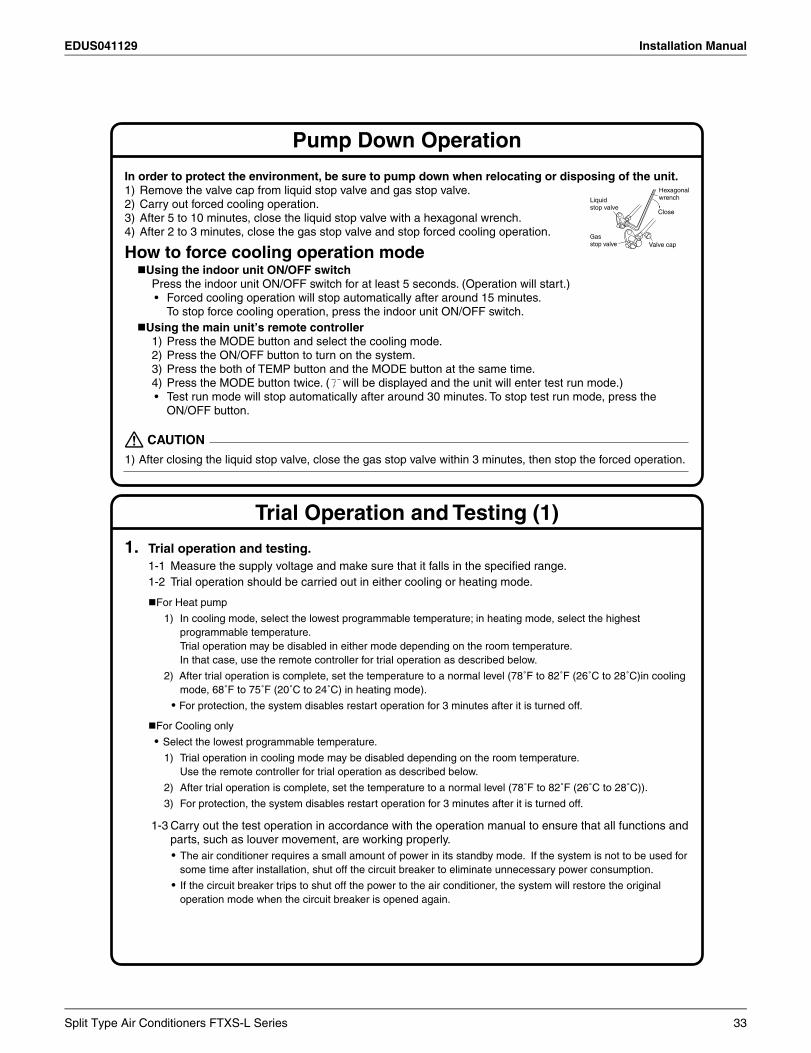
EDUS041129 Installation Manual
Pump Down Operation
Trial Operation and Testing (1)
1. Trial operation and testing.1-1 Measure the supply voltage and make sure that it falls in the specified range.1-2 Trial operation should be carried out in either cooling or heating mode.
For Heat pump
1) In cooling mode, select the lowest programmable temperature; in heating mode, select the highest programmable temperature.Trial operation may be disabled in either mode depending on the room temperature.In that case, use the remote controller for trial operation as described below.
2) After trial operation is complete, set the temperature to a normal level (78˚F to 82˚F (26˚C to 28˚C)in cooling mode, 68˚F to 75˚F (20˚C to 24˚C) in heating mode).
• For protection, the system disables restart operation for 3 minutes after it is turned off.
For Cooling only
• Select the lowest programmable temperature.
1) Trial operation in cooling mode may be disabled depending on the room temperature. Use the remote controller for trial operation as described below.
2) After trial operation is complete, set the temperature to a normal level (78˚F to 82˚F (26˚C to 28˚C)).
3) For protection, the system disables restart operation for 3 minutes after it is turned off.
1-3 Carry out the test operation in accordance with the operation manual to ensure that all functions and parts, such as louver movement, are working properly.• The air conditioner requires a small amount of power in its standby mode. If the system is not to be used for
some time after installation, shut off the circuit breaker to eliminate unnecessary power consumption.
• If the circuit breaker trips to shut off the power to the air conditioner, the system will restore the original operation mode when the circuit breaker is opened again.
1) After closing the liquid stop valve, close the gas stop valve within 3 minutes, then stop the forced operation.
CAUTION
In order to protect the environment, be sure to pump down when relocating or disposing of the unit.1) Remove the valve cap from liquid stop valve and gas stop valve.2) Carry out forced cooling operation.3) After 5 to 10 minutes, close the liquid stop valve with a hexagonal wrench.4) After 2 to 3 minutes, close the gas stop valve and stop forced cooling operation.
How to force cooling operation modeUsing the indoor unit ON/OFF switch
Press the indoor unit ON/OFF switch for at least 5 seconds. (Operation will start.)• Forced cooling operation will stop automatically after around 15 minutes.
To stop force cooling operation, press the indoor unit ON/OFF switch.Using the main unit’s remote controller
1) Press the MODE button and select the cooling mode. 2) Press the ON/OFF button to turn on the system.3) Press the both of TEMP button and the MODE button at the same time. 4) Press the MODE button twice. ( will be displayed and the unit will enter test run mode.) • Test run mode will stop automatically after around 30 minutes. To stop test run mode, press the
ON/OFF button.
Gas stop valve Valve cap
Hexagonal wrench
Close
Liquid stop valve
Split Type Air Conditioners FTXS-L Series 33
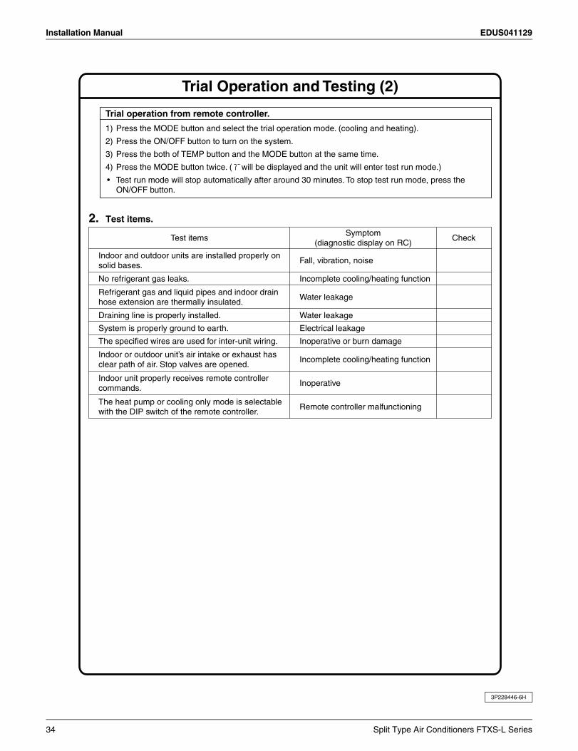
Installation Manual EDUS041129
3P228446-6H
Trial Operation and Testing (2)
Test items
Incomplete cooling/heating functionNo refrigerant gas leaks.
Draining line is properly installed.
Indoor and outdoor units are installed properly on solid bases.
Refrigerant gas and liquid pipes and indoor drain hose extension are thermally insulated.
Fall, vibration, noise
Water leakage
Water leakage
System is properly ground to earth. Electrical leakage
Indoor unit properly receives remote controller commands.
Inoperative
Indoor or outdoor unit’s air intake or exhaust has clear path of air. Stop valves are opened.
Incomplete cooling/heating function
Symptom(diagnostic display on RC)
Check
The specified wires are used for inter-unit wiring. Inoperative or burn damage
The heat pump or cooling only mode is selectable with the DIP switch of the remote controller.
Remote controller malfunctioning
2. Test items.
Trial operation from remote controller.
1) Press the MODE button and select the trial operation mode. (cooling and heating).
2) Press the ON/OFF button to turn on the system.
3) Press the both of TEMP button and the MODE button at the same time.
4) Press the MODE button twice. ( will be displayed and the unit will enter test run mode.)
• Test run mode will stop automatically after around 30 minutes. To stop test run mode, press the ON/OFF button.
34 Split Type Air Conditioners FTXS-L Series
EDUS041129 Installation Manual
11.2 Outdoor UnitSafety Considerations
Read these SAFETY CONSIDERATIONS for Installation carefully before installing an air conditioner or heat pump. After completing the installation, make sure that the unit operates properly during the startup operation.Instruct the customer on how to operate and maintain the unit. Inform customers that they should store this Installation Manual with the Operation Manual for future reference.Always use a licensed installer or contractor to install this product. Improper installation can result in water or refrigerant leakage, electrical shock, fire, or explosion.Meanings of DANGER, WARNING, CAUTION, and NOTE Symbols:
DANGER .............. Indicates an imminently hazardous situation which, if not avoided, will result in death or serious injury.
WARNING ............ Indicates a potentially hazardous situation which, if not avoided, could result in death or serious injury.
CAUTION ............. Indicates a potentially hazardous situation which, if not avoided, may result in minor or moderate injury. It may also be used to alert against unsafe practices.
NOTE .................. Indicates situations that may result in equipment or property-damage accidents only.
• Refrigerant gas is heavier than air and replaces oxygen. A massive leak can lead to oxygen depletion, especially in basements, and an asphyxiation hazard could occur leading to serious injury or death.
• Do not ground units to water pipes, gas pipes, telephone wires, or lightning rods as incomplete grounding can cause a severe shock hazard resulting in severe injury or death. Additionally, grounding to gas pipes could cause a gas leak and potential explosion causing severe injury or death.
• If refrigerant gas leaks during installation, ventilate the area immediately. Refrigerant gas may produce toxic gas if it comes into contact with fire. Exposure to this gas could cause severe injury or death.
• After completing the installation work, check that the refrigerant gas does not leak throughout the system.
• Do not install unit in an area where flammable materials are present due to risk of explosions that can cause serious injury or death.
• Safely dispose all packing and transportation materials in accordance with federal/state/local laws or ordinances. Packing materials such as nails and other metal or wood parts, including plastic packing materials used for transportation may cause injuries or death by suffocation.
• Only qualified personnel must carry out the installation work. Installation must be done in accordance with this installation manual. Improper installation may result in water leakage, electric shock, or fire.
• When installing the unit in a small room, take measures to keep the refrigerant concentration from exceeding allowable safety limits. Excessive refrigerant leaks, in the event of an accident in a closed ambient space, can lead to oxygen deficiency.
• Use only specified accessories and parts for installation work. Failure to use specified parts may result in water leakage, electric shocks, fire, or the unit falling.
• Install the air conditioner or heat pump on a foundation strong enough that it can withstand the weight of the unit. A foundation of insufficient strength may result in the unit falling and causing injuries.
• Take into account strong winds, typhoons, or earthquakes when installing. Improper installation may result in the unit falling and causing accidents.
• Make sure that a separate power supply circuit is provided for this unit and that all electrical work is carried out by qualified personnel according to local. state, and national regulations. An insufficient power supply capacity or improper electrical construction may lead to electric shocks or fire.
• Make sure that all wiring is secured, that specified wires are used, and that no external forces act on the terminal connections or wires. Improper connections or installation may result in fire.
• When wiring, position the wires so that the terminal box lid can be securely fastened. Improper positioning of the terminal box lid may result in electric shocks, fire, or the terminals overheating.
• Before touching electrical parts, turn off the unit.
• Securely fasten the outside unit terminal cover (panel). If the terminal cover/panel is not installed properly, dust or water may enter the outside unit causing fire or electric shock.
• When installing or relocating the system, keep the refrigerant circuit free from substances other than the specified refrigerant (R-410A) such as air. Any presence of air or other foreign substance in the refrigerant circuit can cause an abnormal pressure rise or rupture, resulting in injury.
• Do not change the setting of the protection devices. If the pressure switch, thermal switch, or other protection device is shorted and operated forcibly, or parts other than those specified by Daikin are used, fire or explosion may occur.
• Do not touch the switch with wet fingers. Touching a switch with wet fingers can cause electric shock.
Split Type Air Conditioners FTXS-L Series 35
Installation Manual EDUS041129
• Do not allow children to play on or around the unit to prevent injury.
• The heat exchanger fins are sharp enough to cut. To avoid injury wear gloves or cover the fins while working around them.
• Do not touch the refrigerant pipes during and immediately after operation as the refrigerant pipes may be hot or cold, depending on the condition of the refrigerant flowing through the refrigerant piping, compressor, and other refrigerant cycle parts. Your hands may suffer burns or frostbite if you touch the refrigerant pipes. To avoid injury, give the pipes time to return to normal temperature or, if you must touch them, be sure to wear proper gloves.
• Install drain piping to proper drainage. Improper drain piping may result in water leakage and property damage.
• Insulate piping to prevent condensation.
• Be careful when transporting the product.
• Do not turn off the power immediately after stopping operation. Always wait for at least 5 minutes before turning off the power. Otherwise, water leakage may occur.
• Do not use a charging cylinder. Using a charging cylinder may cause the refrigerant to deteriorate.
• Refrigerant R-410A in the system must be kept clean, dry, and tight.
(a) Clean and Dry -- Foreign materials (including mineral oils such as SUNISO oil or moisture) should be prevented from getting into the system.
(b) Tight -- R-410A does not contain any chlorine, does not destroy the ozone layer, and does not reduce the earth’s protection again harmful ultraviolet radiation. R-410A can contribute to the greenhouse effect if it is released. Therefore take proper measures to check for the tightness of the refrigerant piping installation. Read the chapter Refrigerant Piping and follow the procedures.
• Since R-410A is a blend, the required additional refrigerant must be charged in its liquid state. If the refrigerant is charged in a state of gas, its composition can change and the system will not work properly.
• The indoor unit is for R-410A. See the catalog for indoor models that can be connected. Normal operation is not possible when connected to other units.
• Remote controller (wireless kit) transmitting distance can be shorter than expected in rooms with electronic fluorescent lamps (inverter or rapid start types). Install the indoor unit far away from fluorescent lamps as much as possible.
• Indoor units are for indoor installation only. Outdoor units can be installed either outdoors or indoors. This unit is for indoor use.
• Do not install the air conditioner or heat pump in the following locations:(a) Where a mineral oil mist or oil spray or vapor is
produced, for example, in a kitchen. Plastic parts may deteriorate and fall off or result in water leakage.
(b) Where corrosive gas, such as sulfurous acid gas, is produced.Corroding copper pipes or soldered parts may result in refrigerant leakage.
(c) Near machinery emitting electromagnetic waves. Electromagnetic waves may disturb the operation of the control system and cause the unit to malfunction.
(d) Where flammable gas may leak, where there is carbon fiber, or ignitable dust suspension in the air, or where volatile flammables such as thinner or gasoline are handled. Operating the unit in such conditions can cause a fire.
• Take adequate measures to prevent the outside unit from being used as a shelter by small animals. Small animals making contact with electrical parts can cause malfunctions, smoke, or fire. Instruct the customer to keep the area around the unit clean.
• Install the power supply and control wires for the indoor and outdoor units at least 3.5 feet away from televisions or radios to prevent image interference or noise. Depending on the radio waves, a distance of 3.5 feet may not be sufficient to eliminate the noise.
• Dismantling the unit, treatment of the refrigerant, oil and additional parts must be done in accordance with the relevant local, state, and national regulations.
• Do not use the following tools that are used with conventional refrigerants: gauge manifold, charge hose, gas leak detector, reverse flow check valve, refrigerant charge base, vacuum gauge, or refrigerant recovery equipment.
• If the conventional refrigerant and refrigerator oil are mixed in R-410A, the refrigerant may deteriorate.
• This air conditioner or heat pump is an appliance that should not be accessible to the general public.
• As design pressure is 478 psi, the wall thickness of field-installed pipes should be selected in accordance with the relevant local, state, and national regulations.
36 Split Type Air Conditioners FTXS-L Series
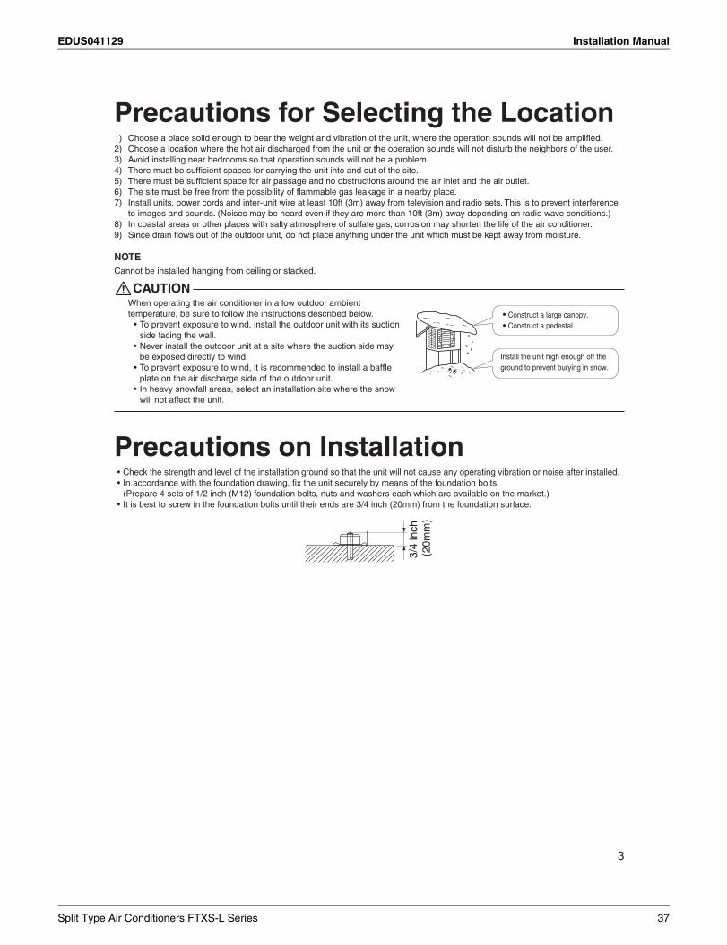
EDUS041129 Installation Manual
3
Precautions for Selecting the Location
NOTE
CAUTION
Construct a large canopy.Construct a pedestal.
Install the unit high enough off the ground to prevent burying in snow.
Precautions on Installation3/
4 in
ch
(20m
m)
Split Type Air Conditioners FTXS-L Series 37
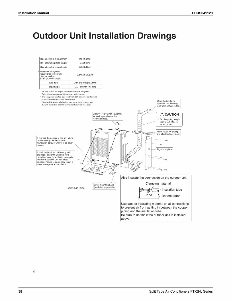
Installation Manual EDUS041129
Outdoor Unit Installation Drawings
Max. allowable piping height
Min. allowable piping length
Max. allowable piping length 98.4ft (30m)
6.56ft (2m)
65.6ft (20m)
Liquid pipe
Gas pipe
O.D. 3/8 inch (9.5mm)
O.D. 5/8 inch (15.9mm)
0.54oz/ft (50g/m)
Additional refrigerant required for refrigerant pipe exceeding 32.8ft (10m) in length.
**
*
* Be sure to add the proper amount of additional refrigerant. Failure to do so may result in reduced performance.
** The suggested shortest pipe length is 6.56ft (2m), in order to avoid noise from the outdoor unit and vibration. (Mechanical noise and vibration may occur depending on how the unit is installed and the environment in which it is used.)
Wrap the insulation
tape from bottom to top.
Allow 11-13/16 inch (300mm) of work space below the ceiling surface.
9-7/8 (250) from wallAllow space for piping and electrical servicing.
Right side plate
13-3/4
(350)
Clamping material
Insulation tube
Bottom frameTape
Also insulate the connection on the outdoor unit.
Use tape or insulating material on all connections to prevent air from getting in between the copper piping and the insulation tube.Be sure to do this if the outdoor unit is installed above.
(Foot bolt-h
ole
centers)
(Foot bolt-hole centers)
24-7/16(620)
Level mounting base (available separately)
If there is the danger of the unit falling
foundation bolts, or with wire or other means.
If the location does not have good drainage, place the unit on a level mounting base (or a plastic pedestal). Install the outdoor unit in a level position. Failure to do so may result in water leakage or accumulation.
CAUTION** Set the piping length from 6.56ft (2m) to 98.4ft (30m).
unit : inch (mm)
38 Split Type Air Conditioners FTXS-L Series
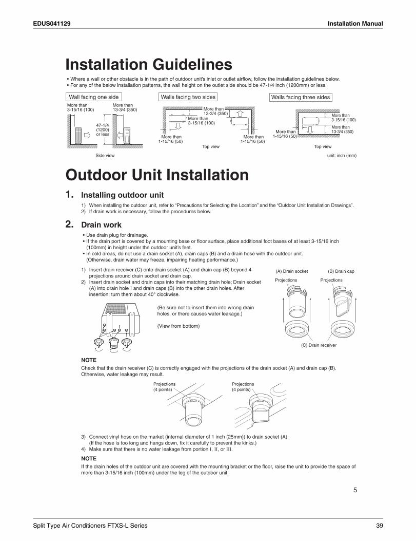
EDUS041129 Installation Manual
5
Installation Guidelines
More than 3-15/16 (100)
More than 13-3/4 (350)
Side view
47-1/4(1200)or less
More than 1-15/16 (50)
More than 1-15/16 (50)
More than 13-3/4 (350)
Top view
More than 3-15/16 (100)
unit: inch (mm)
Wall facing one side Walls facing two sides
Top view
More than 3-15/16 (100)
More than 13-3/4 (350)More than
1-15/16 (50)
Walls facing three sides
Outdoor Unit Installation1. Installing outdoor unit
2. Drain work
I
Projections Projections
(C) Drain receiver
(A) Drain socket (B) Drain cap
I
NOTE
Projections(4 points)
Projections(4 points)
I II III
NOTE
Split Type Air Conditioners FTXS-L Series 39
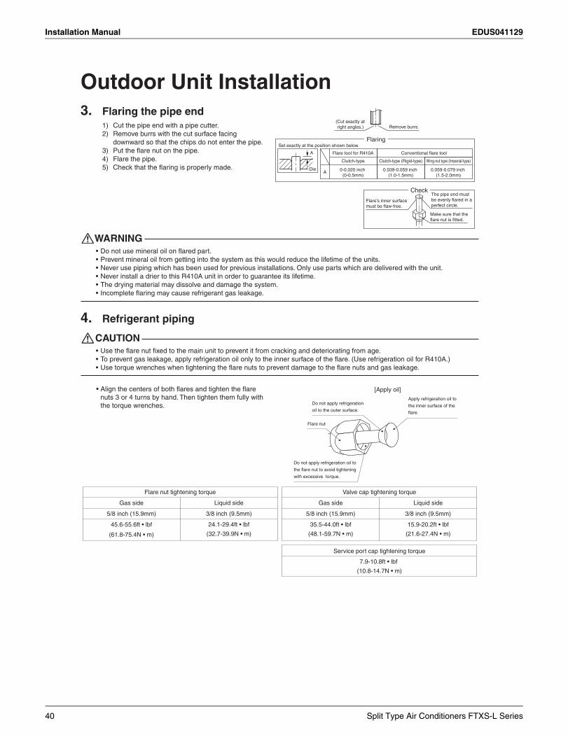
Installation Manual EDUS041129
Outdoor Unit Installation3. Flaring the pipe end
WARNING
4. Refrigerant piping
CAUTION
Flare nut tightening torque
Liquid side
3/8 inch (9.5mm)
Gas side
5/8 inch (15.9mm)
Valve cap tightening torque
Liquid side
3/8 inch (9.5mm)
Gas side
5/8 inch (15.9mm)
Service port cap tightening torque
Do not apply refrigeration
oil to the outer surface.
Flare nut
Apply refrigeration oil to
the inner surface of the
Do not apply refrigeration oil to
with excessive torque.
[Apply oil]
the torque wrenches.
(Cut exactly at right angles.) Remove burrs.
Set exactly at the position shown below.
A
Flaring
Die
Check
Flare’s inner surface The pipe end must
perfect circle.
Make sure that the
A
Flare tool for R410A
40 Split Type Air Conditioners FTXS-L Series
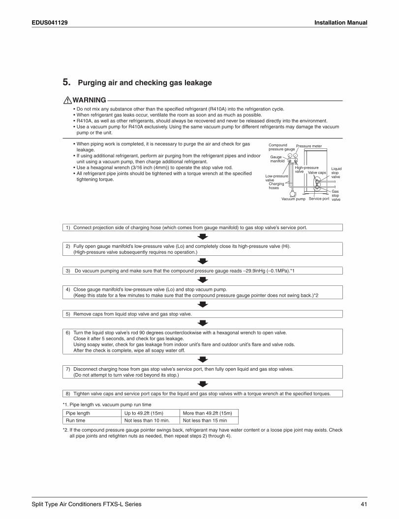
EDUS041129 Installation Manual
5. Purging air and checking gas leakage
WARNING
Gaugemanifold
Compoundpressure gauge
Pressure meter
Low-pressure valve
High-pressurevalve
Charginghoses
Vacuum pump
Valve caps
Service port
Liquidstopvalve
Gasstopvalve
Split Type Air Conditioners FTXS-L Series 41
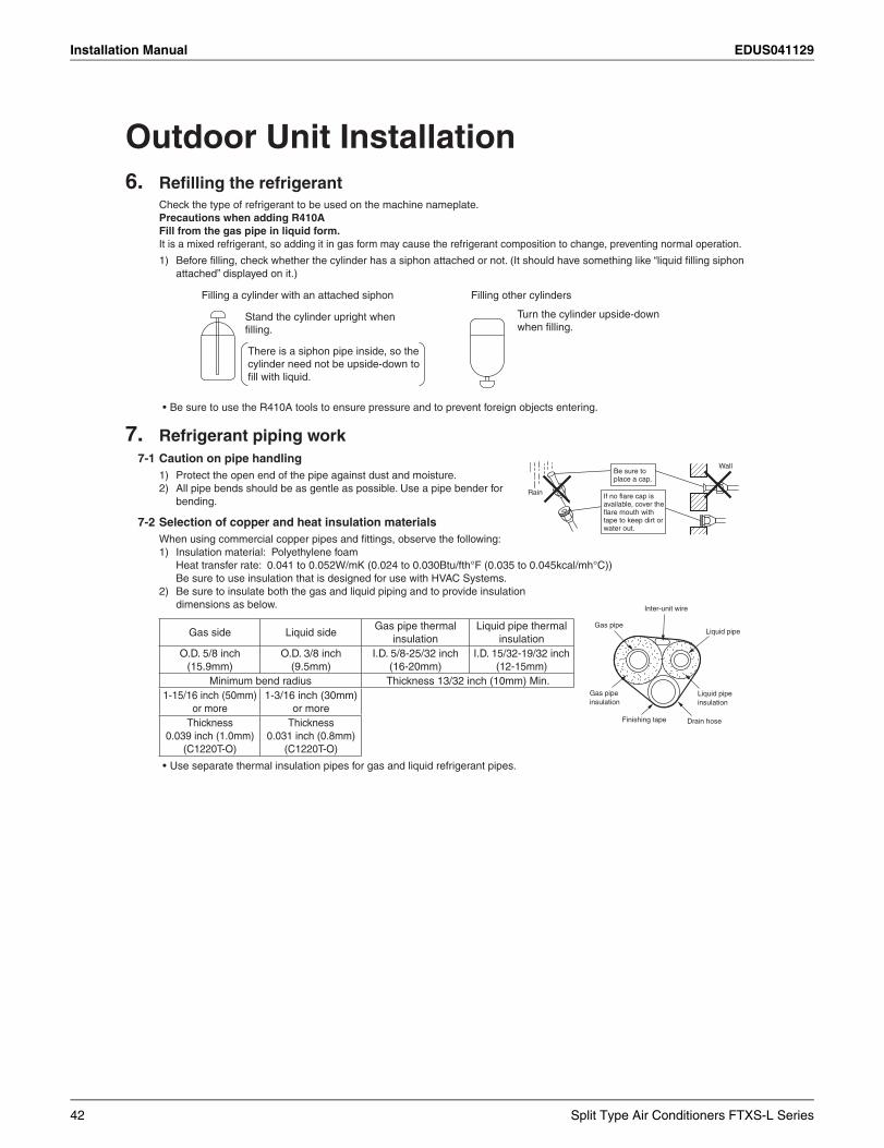
Installation Manual EDUS041129
Outdoor Unit Installation6.
Precautions when adding R410AFill from the gas pipe in liquid form.
Filling a cylinder with an attached siphon
Stand the cylinder upright when
There is a siphon pipe inside, so the cylinder need not be upside-down to
Filling other cylinders
Turn the cylinder upside-down
7. Refrigerant piping work7-1 Caution on pipe handling
7-2 Selection of copper and heat insulation materials
Wall
Gas pipeLiquid pipe
Gas pipe insulation
Liquid pipe insulation
Finishing tape Drain hose
Inter-unit wire
42 Split Type Air Conditioners FTXS-L Series
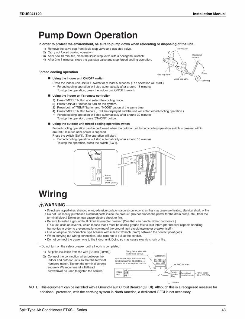
EDUS041129 Installation Manual
NOTE: This equipment can be installed with a Ground-Fault Circuit Breaker (GFCI). Although this is a recognized measure for additional protection, with the earthing system in North America, a dedicated GFCI is not necessary.
9
Pump Down OperationIn order to protect the environment, be sure to pump down when relocating or disposing of the unit.
Forced cooling operation
Using the indoor unit ON/OFF switch
Using the indoor unit’s remote controller
Using the outdoor unit forced cooling operation switch
LED-A
SW4ON
AB
CD
S102
SW1
S2
Forcedcoolingoperation switch (SW1)
Wiring WARNING
Close
valve cap
Hexagonal wrench
Service port
Liquid stop valve
Gas stop valve
123
1 2 3
Safety breaker 20A
Ground faultcircuit interrupter
Ground
Outdoor unit
Indoorunit 60Hz 208-230V
L1 L2 GR
Split Type Air Conditioners FTXS-L Series 43
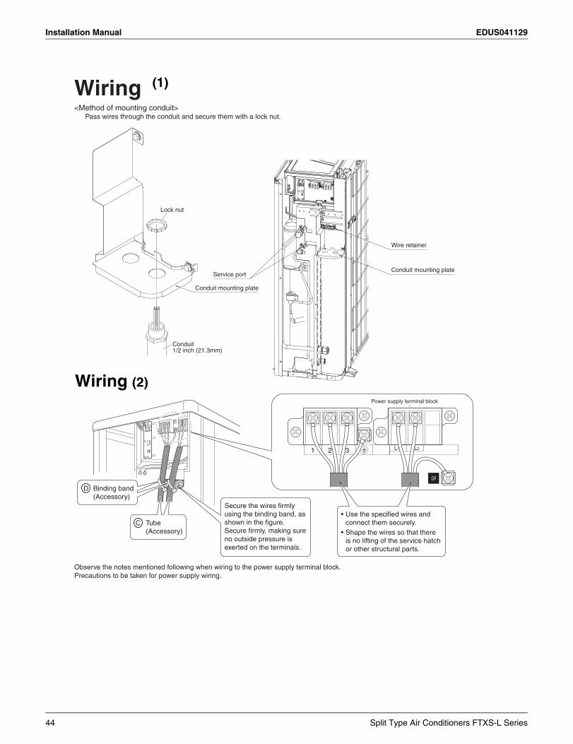
Installation Manual EDUS041129
Wiring
Wire retainer
Conduit mounting plateService port
Lock nut
Conduit1/2 inch (21.3mm)
Conduit mounting plate
Tube(Accessory)
Binding band(Accessory)
using the binding band, as
no outside pressure is
L1 L21 2 3
D
C
(1)
Wiring (2)
44 Split Type Air Conditioners FTXS-L Series
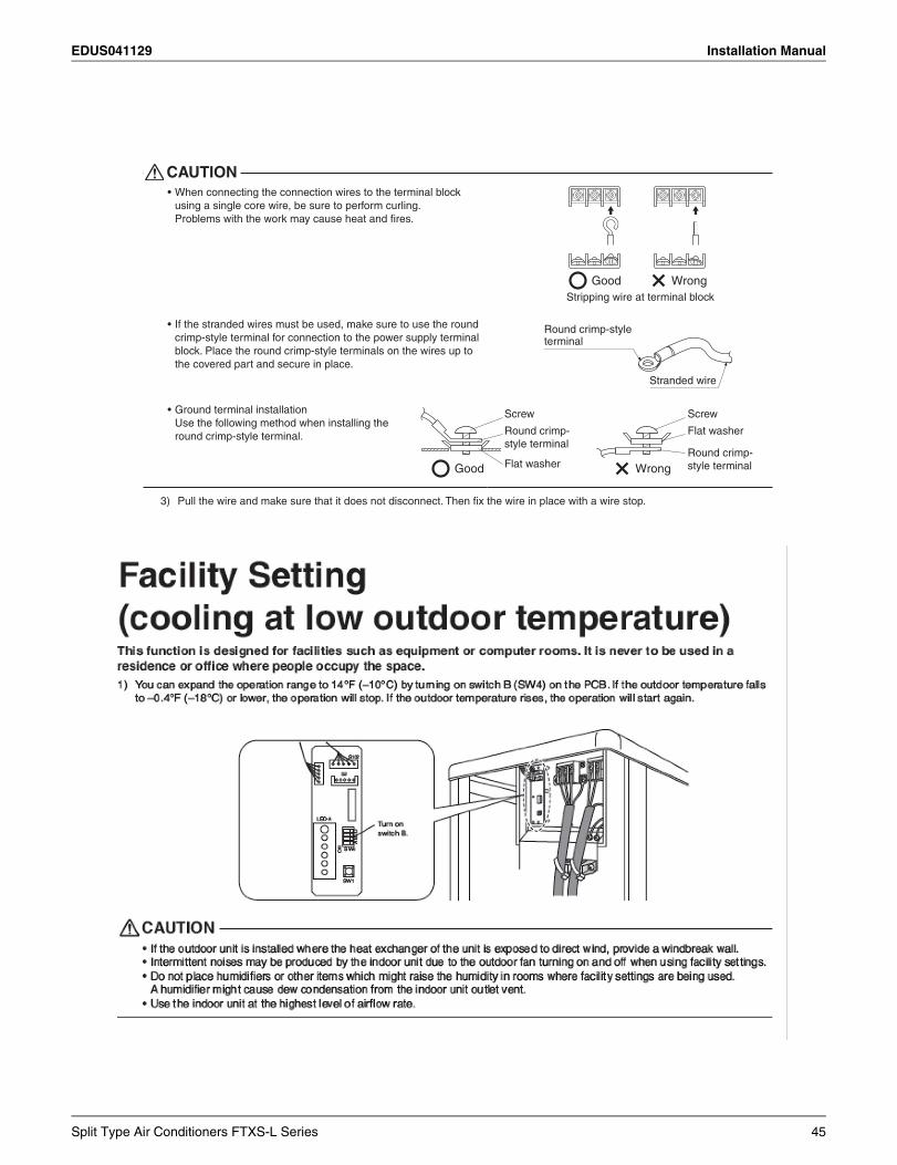
EDUS041129 Installation Manual
CAUTION
Stranded wire
Round crimp-styleterminal
Good Wrong
Round crimp-style terminal
Flat washer
Screw
Flat washer
Round crimp-style terminal
Screw
Stripping wire at terminal block
Good Wrong
Split Type Air Conditioners FTXS-L Series 45
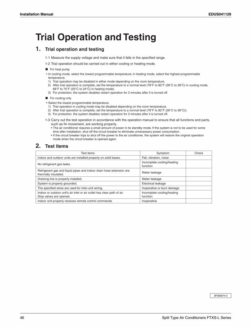
Installation Manual EDUS041129
3P300674-3
Trial Operation and Testing1. Trial operation and testing
2. Test items
46 Split Type Air Conditioners FTXS-L Series
EDUS041129 Operation Manual
12.Operation Manual
Safety ConsiderationsRead these SAFETY CONSIDERATIONS for Operations carefully before operating an air conditioner or heat pump. Make sure that the unit operates properly during the startup operation. Instruct the customer on how to operate and maintain the unit. Inform customers that they should store this Operation Manual with the Installation Manual for future reference.Meanings of DANGER, WARNING, CAUTION, and NOTE Symbols:
DANGER ................... Indicates an imminently hazardous situation which, if not avoided, will result in death or serious injury.
WARNING ................. Indicates a potentially hazardous situation which, if not avoided, could result in death or serious injury.
CAUTION .................. Indicates a potentially hazardous situation which, if not avoided, may result in minor or moderate injury. It may also be used to alert against unsafe practices.
NOTE ....................... Indicates situations that may result in equipment or property-damage accidents only.
• Do not install the unit in an area where flammable materials are present due to risk of explosion resulting in serious injury or death.
• Any abnormalities in the operation of the air conditioner or heat pump, such as smoke or fire, could result in severe injury or death. Turn off the power and contact your dealer immediately.
• Refrigerant gas may produce toxic gas if it comes into contact with fire, such as from a fan, heater, stove, or cooking device. Exposure to this gas could cause severe injury or death.
• For refrigerant leakage, consult your dealer. Refrigerant gas is heavier than air and replaces oxygen. A massive leak could lead to oxygen depletion, especially in basements, and an asphyxiation hazard could occur leading to serious injury or death.
• If equipment utilizing a burner is used in the same room as the air conditioner or heat pump, there is the danger of oxygen deficiency which could lead to an asphyxiation hazard resulting in serious injury or death. Be sure to ventilate the room sufficiently to avoid this hazard.
• Safely dispose of the packing materials. Packing materials, such as nails and other metal or wooden parts, may cause stabs or other injuries.
• Tear apart and throw away plastic packaging bags so that children will not play with them. Children playing with plastic bags face the danger of death by suffocation.
• Contact your dealer for repair and maintenance. Improper repair and maintenance may result in water leakage, electric shock, and fire. Only use accessories made by Daikin that are specifically designed for use with the equipment and have them installed by a professional.
• Contact your dealer to move and reinstall the air conditioner or heat pump. Incomplete installation may result in water leakage, electric shock, and fire.
• Never let the indoor unit or the remote controller get wet. Water can cause an electric shock or a fire.
• Never use flammable spray such as hair spray, lacquer, or paint near the unit. Flammable spray may cause a fire.
• When a fuse blows out, never replace it with one of incorrect ampere ratings or different wires. Always replace any blown fuse with a fuse of the same specification.
• Never remove the fan guard of the unit. A fan rotating at high speed without the fan guard is very dangerous.
• Never inspect or service the unit by yourself. Contact a qualified service person to perform this work.
• Turn off all electrical power before doing any maintenance to avoid the risk of serious electric shock; never sprinkle or spill water or liquids on the unit.
• Do not touch the switch with wet fingers. Touching a switch with wet fingers can cause electric shock.
• Do not allow children to play on or around the unit to prevent injury.
• The heat exchanger fins are sharp enough to cut. To avoid injury wear gloves or cover the fins while working around them.
• Do not put a finger or other objects into the air inlet or air outlet. The fan is rotating at high speed and will cause injury.
• Check the unit foundation for damage on a continuous basis, especially if it has been in use for a long time. If left in a damaged condition the unit may fall and cause injury.
• Placing a flower vase or other containers with water or other liquids on the unit could cause a shock or fire if a spill occurs.
• Do not touch the air outlet or horizontal blades while the swing flap is in operation because fingers could get caught and injured.
• Never touch the internal parts of the controller. Do not remove the front panel because some parts inside are dangerous to touch. To check and adjust internal parts, contact your dealer.
• Do not use the air conditioner or heat pump for any other purposes other than comfort cooling or heating. Do not use the unit for cooling precision instruments, food, plants, animals or works of art.
• Do not place items under the indoor unit as they may be damaged by condensates that may form if the humidity is above 80% or if the drain outlet gets blocked.
Split Type Air Conditioners FTXS-L Series 47
Operation Manual EDUS041129
• Before cleaning, stop the operation of the unit by turning the power off or by pulling the supply cord out from its receptacle. Otherwise, an electric shock and injury may result.
• Do not wash the air conditioner or heat pump with excessive water. An electric shock or fire may result.
• Avoid placing the controller in a spot splashed with water. Water entering the controller may cause an electric shock or damage the internal electronic parts.
• Do not operate the air conditioner or heat pump when using a room-fumigation type of insecticide. Failure to observe this could cause the chemicals to be deposited in the unit and can endanger the health of those who are hypersensitive to chemicals.
• Do not turn off the power immediately after stopping operation. Always wait for at least five minutes before turning off the power. Otherwise, water leakage may occur.
• The appliance is not intended for use by young children or infirm persons without supervision.
• The remote controller should be kept away from children so they cannot play with it.
• Consult with the installation contractor for cleaning.
• Incorrect cleaning of the inside of the air conditioner or heat pump could make the plastics parts break and cause water leakage or electric shock.
• Do not touch the air inlet or aluminum fin of the air conditioner or heat pump as they can cut and cause injury.
• Do not place objects in direct proximity of the outside unit. Do not let leaves and other debris accumulate around the unit. Leaves are a hotbed for small animals which can enter the unit. Once inside the unit, animals can cause the unit to malfunction, and cause smoke or fire when they make contact with electrical parts.
• Never press the button of the remote controller with a hard, pointed object. The remote controller may be damaged.
• Never pull or twist the electric wire of the remote controller. It may cause the unit to malfunction.
• Do not place appliances that produce open flames in places that are exposed to the air flow of the unit or under the indoor unit. It may cause incomplete combustion or deformation of the unit due to the heat.
• Do not expose the controller to direct sunlight. The LCD display can become discolored and may fail to display the data.
• Do not wipe the controller operation panel with benzene, thinner, chemical dust cloth, etc. The panel may get
discolored or the coating can peel off. If it is heavily dirty, soak a cloth in water-diluted neutral detergent, squeeze it well and wipe the panel clean. Then wipe it with another dry cloth.
• Dismantling of the unit, disposal of the refrigerant, oil, and additional parts, should be done in accordance with the relevant local, state, and national regulations.
• Operate the air conditioner or heat pump in a sufficiently ventilated area and not surrounded by obstacles. Do not use the air conditioner or heat pump in the following places.a. Places with a mist of mineral oil, such as cutting oil.b. Locations such as coastal areas where there is a lot of salt
in the air.c. Locations such as hot springs where there is a lot of sulfur
in the air.d. Locations such as factories where the power voltage varies
a lot.e. In cars, boats, and other vehicles.f. Locations such as kitchens where oil may splatter or where
there is steam in the air.g. Locations where equipment produces electromagnetic
waves.h. Places with an acid or alkaline mist.i. Places where fallen leaves can accumulate or where weeds
can grow.
• Take snow protection measures. Contact your dealer for the details of snow protection measures, such as the use of a snow protection hood.
• Do not attempt to do electrical work or grounding work unless you are licensed to do so. Consult with your dealer for electrical work and grounding work.
• Pay Attention to Operating Sound. Be sure to use the following places: a. Places that can sufficiently withstand the weight of the air
conditioner or heat pump yet can suppress the operating sound and vibration.
b. Places where warm air from the air outlet of the outside unit or the operating sound of the outside unit does not annoy neighbors.
• Make sure that there are no obstacles close to the outside unit. Obstacles close to the outside unit may drop the performance of the outside unit or increase the operating sound of the outside unit.
• Consult your dealer if the air conditioner or heat pump in operation generates unusual noise.
• Make sure that the drainpipe is installed properly to drain water. If no water is discharged from the drainpipe while the air conditioner or heat pump is in the cooling mode, the drainpipe may be clogged with dust or dirt and water leakage from the indoor unit may occur. Stop operating the air conditioner or heat pump and contact your dealer.
48 Split Type Air Conditioners FTXS-L Series
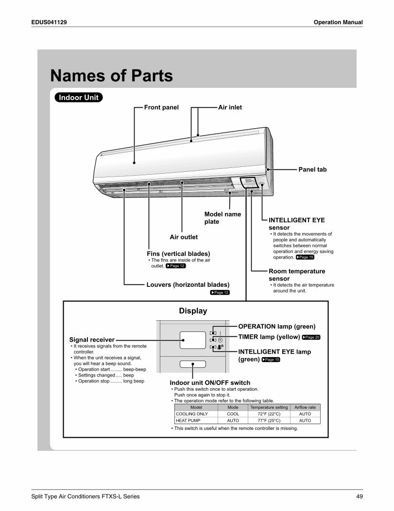
EDUS041129 Operation Manual
Names of PartsIndoor Unit
Panel tab
INTELLIGENT EYE sensor
It detects the movements of •people and automatically switches between normal operation and energy saving operation. Page 15
Room temperature sensor
It detects the air temperature •around the unit.
OPERATION lamp (green)TIMER lamp (yellow) Page 20
INTELLIGENT EYE lamp (green) Page 15
Signal receiverIt receives signals from the remote •controller.When the unit receives a signal, •you will hear a beep sound.
Operation start• ......... beep-beepSettings changed• ..... beepOperation stop• ......... long beep
Display
Indoor unit ON/OFF switchPush this switch once to start operation.•Push once again to stop it.The operation mode refer to the following table.•
Model Mode Temperature setting Airfl ow rateCOOLING ONLY COOL 72°F (22°C) AUTOHEAT PUMP AUTO 77°F (25°C) AUTO
This switch is useful when the remote controller is missing.•
Air inletFront panel
Model name plate
Air outlet
Fins (vertical blades)The fi ns are inside of the air •outlet. Page 12
Louvers (horizontal blades) Page 12
Split Type Air Conditioners FTXS-L Series 49
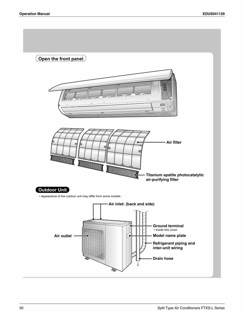
Operation Manual EDUS041129
Outdoor Unit
Open the front panel
Appearance of the outdoor unit may differ from some models.•
Refrigerant piping and inter-unit wiring
Ground terminalInside this cover.•
Drain hose
Model name plate
Air inlet: (back and side)
Air outlet
Air fi lter
Titanium apatite photocatalytic air-purifying fi lter
50 Split Type Air Conditioners FTXS-L Series
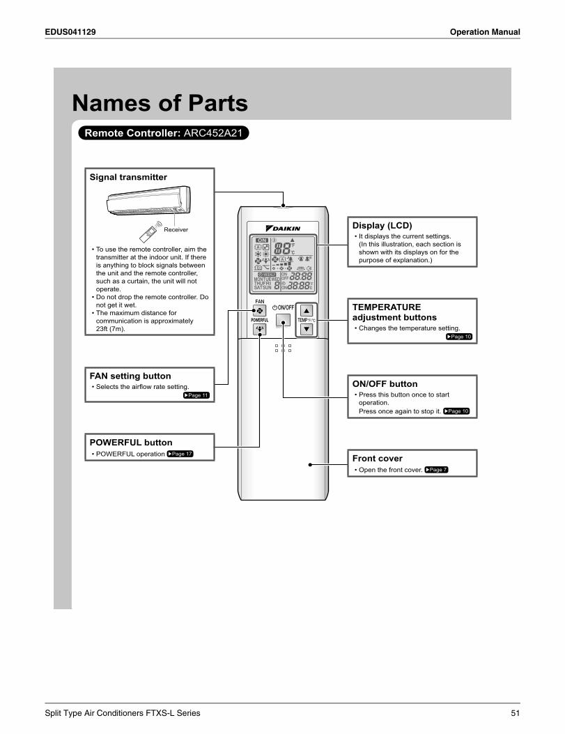
EDUS041129 Operation Manual
Names of PartsRemote Controller: ARC452A21
Signal transmitter
Receiver
To use the remote controller, aim the •transmitter at the indoor unit. If there is anything to block signals between the unit and the remote controller, such as a curtain, the unit will not operate.Do not drop the remote controller. Do •not get it wet.The maximum distance for •communication is approximately 23ft (7m).
FAN setting buttonSelects the airfl ow rate setting.•
Page 11
POWERFUL buttonPOWERFUL operation • Page 17
Display (LCD)It displays the current settings.•(In this illustration, each section is shown with its displays on for the purpose of explanation.)
TEMPERATURE adjustment buttons
Changes the temperature setting.•Page 10
ON/OFF buttonPress this button once to start •operation.Press once again to stop it. Page 10
Front coverOpen the front cover. • Page 7
Split Type Air Conditioners FTXS-L Series 51
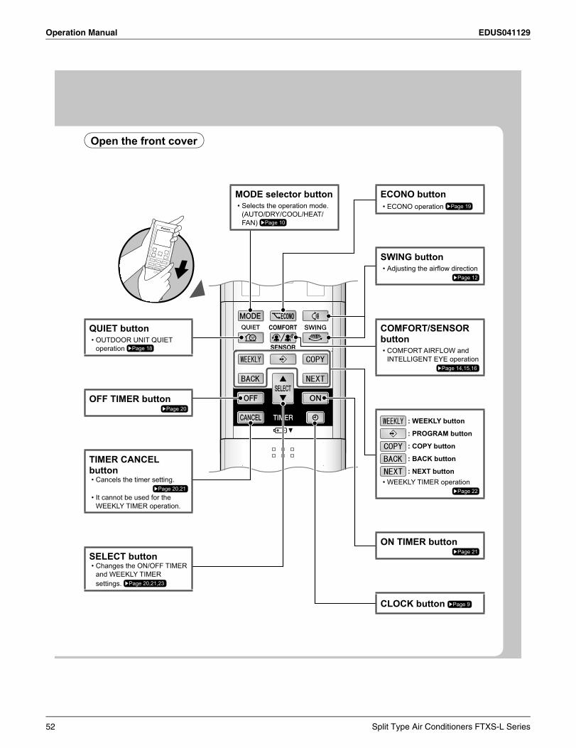
Operation Manual EDUS041129
Open the front cover
ECONO buttonECONO operation • Page 19
SWING buttonAdjusting the airfl ow direction•
Page 12
COMFORT/SENSORbutton
COMFORT AIRFLOW and •INTELLIGENT EYE operation
Page 14,15,16
: WEEKLY button
: PROGRAM button
: COPY button
: BACK button
: NEXT buttonWEEKLY TIMER operation•
Page 22
ON TIMER buttonPage 21
CLOCK button Page 9
QUIET buttonOUTDOOR UNIT QUIET •operation Page 18
OFF TIMER buttonPage 20
TIMER CANCEL button
Cancels the timer setting.•Page 20,21
It cannot be used for the •WEEKLY TIMER operation.
SELECT buttonChanges the ON/OFF TIMER •and WEEKLY TIMER settings. Page 20,21,23
MODE selector buttonSelects the operation mode. •(AUTO/DRY/COOL/HEAT/FAN) Page 10
52 Split Type Air Conditioners FTXS-L Series
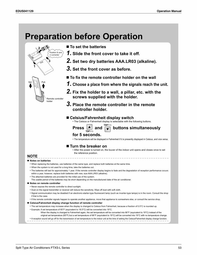
EDUS041129 Operation Manual
Preparation before OperationTo set the batteries
Slide the front cover to take it off.1.Set two dry batteries AAA.LR03 (alkaline).2.Set the front cover as before.3.
To fi x the remote controller holder on the wall
Choose a place from where the signals reach the unit.1.Fix the holder to a wall, a pillar, etc. with the 2.screws supplied with the holder.
Place the remote controller in the remote 3.controller holder.
Celsius/Fahrenheit display switchThe Celsius or Fahrenheit display is selectable with the following buttons.•
Press and buttons simultaneously for 5 seconds.
The temperature will be displayed in Fahrenheit if it is presently displayed in Celsius, and vice versa.•
Turn the breaker onAfter the power is turned on, the louver of the indoor unit opens and closes once to set •the reference position.
2
31
Position and correctly!
+–
Remote controller holder
Set. Pull.
NOTENotes on batteries
When replacing the batteries, use batteries of the same type, and replace both batteries at the same time.•When the system is not used for a long time, take the batteries out.•The batteries will last for approximately 1 year. If the remote controller display begins to fade and the degradation of reception performance occurs •within a year, however, replace both batteries with new, size AAA.LR03 (alkaline).The attached batteries are provided for the initial use of the system.•The usable period of the batteries may be short depending on the manufactured date of the air conditioner.
Notes on remote controllerNever expose the remote controller to direct sunlight.•Dust on the signal transmitter or receiver will reduce the sensitivity. Wipe off dust with soft cloth.•Signal communication may be disabled if an electronic-starter-type fl uorescent lamp (such as inverter-type lamps) is in the room. Consult the shop •if that is the case.If the remote controller signals happen to operate another appliance, move that appliance to somewhere else, or consult the service shop.•
Celsius/Fahrenheit display change function of remote controllerThe set temperature may increase when the display is changed to Celsius from Fahrenheit, because a fraction of 0.5°C is rounded up.•Example: A set temperature of 65°F (equivalent to 18.5°C) will be converted into 19°C.•
When the display is changed to Fahrenheit again, the set temperature will be converted into 66°F (equivalent to 19°C) instead of the original set temperature (65°F) but a set temperature of 66°F (equivalent to 19°C) will be converted into 19°C with no temperature change.
A reception sound will go off for the transmission of set temperature to the indoor unit at the time of setting the Celsius/Fahrenheit display change function.•
Split Type Air Conditioners FTXS-L Series 53
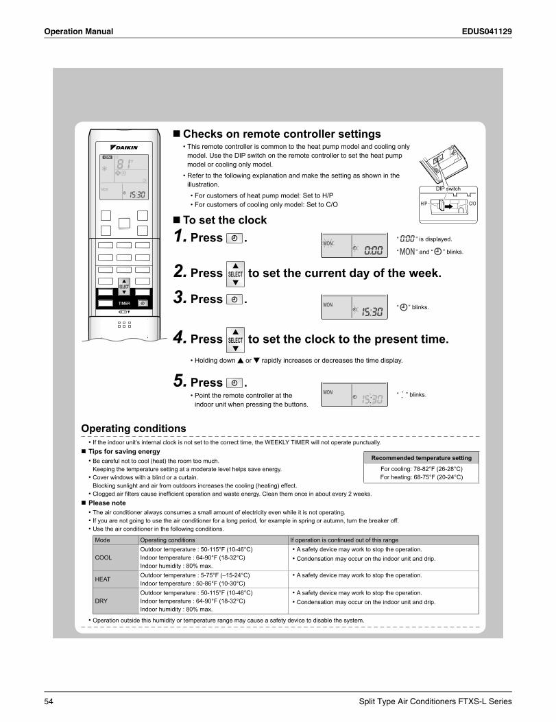
Operation Manual EDUS041129
9
Checks on remote controller settings This remote controller is common to the heat pump model and cooling only •model. Use the DIP switch on the remote controller to set the heat pump model or cooling only model. Refer to the following explanation and make the setting as shown in the •illustration.
For customers of heat pump model: Set to H/P•For customers of cooling only model: Set to C/O•
To set the clockPress1. . ” is displayed.
” and “ ” blinks.
“
“
Press2. to set the current day of the week.
Press3. . “ ” blinks.
Press4. to set the clock to the present time.Holding down • or rapidly increases or decreases the time display.
Press5. .Point the remote controller at the •indoor unit when pressing the buttons.
“ ” blinks.
Operating conditionsIf the indoor unit’s internal clock is not set to the correct time, the WEEKLY TIMER will not operate punctually.•
Tips for saving energyBe careful not to cool (heat) the room too much. •Keeping the temperature setting at a moderate level helps save energy.Cover windows with a blind or a curtain.•Blocking sunlight and air from outdoors increases the cooling (heating) effect.Clogged air fi lters cause ineffi cient operation and waste energy. Clean them once in about every 2 weeks.•
Please noteThe air conditioner always consumes a small amount of electricity even while it is not operating.•If you are not going to use the air conditioner for a long period, for example in spring or autumn, turn the breaker off.•Use the air conditioner in the following conditions.•Mode Operating conditions If operation is continued out of this range
COOLOutdoor temperature : 50-115°F (10-46°C)Indoor temperature : 64-90°F (18-32°C)Indoor humidity : 80% max.
A safety device may work to stop the operation. •Condensation may occur on the indoor unit and drip.•
HEATOutdoor temperature : 5-75°F (–15-24°C)Indoor temperature : 50-86°F (10-30°C)
A safety device may work to stop the operation.•
DRYOutdoor temperature : 50-115°F (10-46°C)Indoor temperature : 64-90°F (18-32°C)Indoor humidity : 80% max.
A safety device may work to stop the operation.•Condensation may occur on the indoor unit and drip.•
Operation outside this humidity or temperature range may cause a safety device to disable the system.•
Recommended temperature setting
For cooling: 78-82°F (26-28°C)For heating: 68-75°F (20-24°C)
H/P C/O
DIP switch
54 Split Type Air Conditioners FTXS-L Series
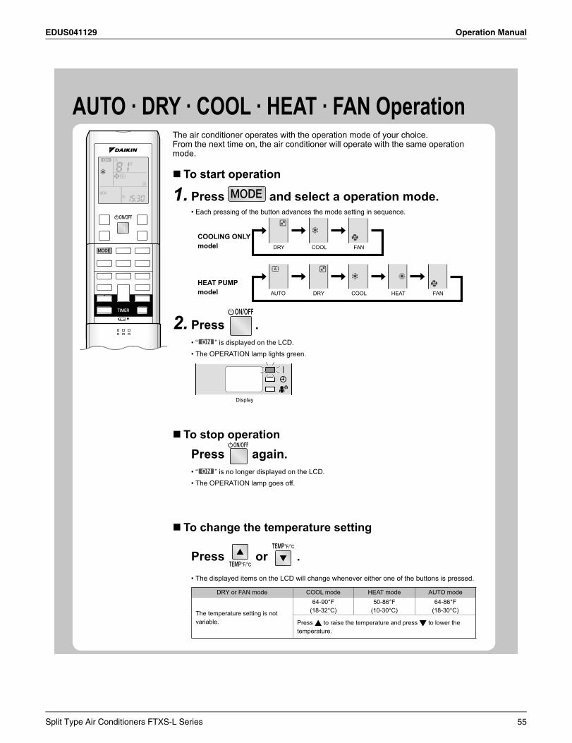
EDUS041129 Operation Manual
AUTO · DRY · COOL · HEAT · FAN OperationThe air conditioner operates with the operation mode of your choice.From the next time on, the air conditioner will operate with the same operation mode.
To start operation
Press1. and select a operation mode.Each pressing of the button advances the mode setting in sequence.•
COOLING ONLY model DRY COOL FAN
HEAT PUMP model AUTO DRY COOL HEAT FAN
Press2. .“ • ” is displayed on the LCD.The OPERATION lamp lights green.•
Display
To stop operationPress again.
“ • ” is no longer displayed on the LCD.The OPERATION lamp goes off.•
To change the temperature setting
Press or .The displayed items on the LCD will change whenever either one of the buttons is pressed.•
DRY or FAN mode COOL mode HEAT mode AUTO mode
The temperature setting is not variable.
64-90°F(18-32°C)
50-86°F(10-30°C)
64-86°F(18-30°C)
Press to raise the temperature and press to lower the temperature.
Split Type Air Conditioners FTXS-L Series 55
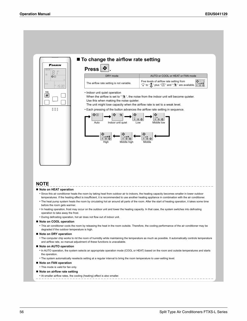
Operation Manual EDUS041129
To change the airfl ow rate setting
Press .DRY mode AUTO or COOL or HEAT or FAN mode
The airfl ow rate setting is not variable.Five levels of airfl ow rate setting from “ ” to “ ” plus “ ” and “ ” are available.
Indoor unit quiet operation•When the airfl ow is set to “ ”, the noise from the indoor unit will become quieter.Use this when making the noise quieter.The unit might lose capacity when the airfl ow rate is set to a weak level.Each pressing of the button advances the airfl ow rate setting in sequence.•
Auto Indoor unit quiet Low Middle low
MiddleMiddle highHigh
NOTENote on HEAT operation
Since this air conditioner heats the room by taking heat from outdoor air to indoors, the heating capacity becomes smaller in lower outdoor •temperatures. If the heating effect is insuffi cient, it is recommended to use another heating appliance in combination with the air conditioner.The heat pump system heats the room by circulating hot air around all parts of the room. After the start of heating operation, it takes some time •before the room gets warmer.In heating operation, frost may occur on the outdoor unit and lower the heating capacity. In that case, the system switches into defrosting •operation to take away the frost.During defrosting operation, hot air does not fl ow out of indoor unit.•
Note on COOL operationThis air conditioner cools the room by releasing the heat in the room outside. Therefore, the cooling performance of the air conditioner may be •degraded if the outdoor temperature is high.
Note on DRY operationThe computer chip works to rid the room of humidity while maintaining the temperature as much as possible. It automatically controls temperature •and airfl ow rate, so manual adjustment of these functions is unavailable.
Note on AUTO operationIn AUTO operation, the system selects an appropriate operation mode (COOL or HEAT) based on the room and outside temperatures and starts •the operation.The system automatically reselects setting at a regular interval to bring the room temperature to user-setting level.•
Note on FAN operationThis mode is valid for fan only.•
Note on airfl ow rate settingAt smaller airfl ow rates, the cooling (heating) effect is also smaller.•
56 Split Type Air Conditioners FTXS-L Series
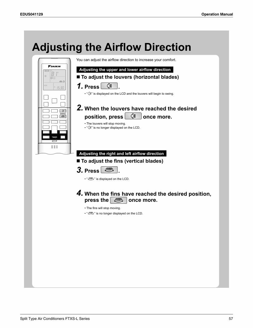
EDUS041129 Operation Manual
Adjusting the Airfl ow DirectionYou can adjust the airfl ow direction to increase your comfort.
Adjusting the upper and lower airfl ow direction
To adjust the louvers (horizontal blades)
Press1. .“ • ” is displayed on the LCD and the louvers will begin to swing.
When the louvers have reached the desired 2.position, press once more.
The louvers will stop moving.•“ • ” is no longer displayed on the LCD.
Adjusting the right and left airfl ow direction
To adjust the fi ns (vertical blades)
Press3. .“ • ” is displayed on the LCD.
When the fi ns have reached the desired position, 4.press the once more.
The fi ns will stop moving.•
“ • ” is no longer displayed on the LCD.
Split Type Air Conditioners FTXS-L Series 57
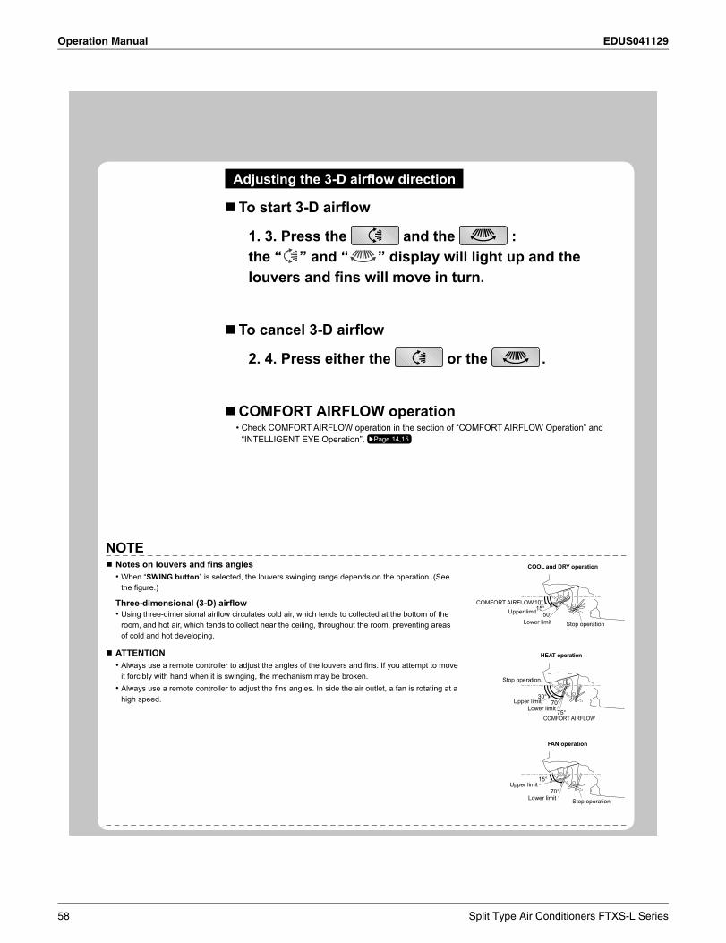
Operation Manual EDUS041129
Adjusting the 3-D airfl ow direction
To start 3-D airfl ow
1. 3. Press the and the :the “ ” and “ ” display will light up and the louvers and fi ns will move in turn.
To cancel 3-D airfl ow
2. 4. Press either the or the .
COMFORT AIRFLOW operationCheck COMFORT AIRFLOW operation in the section of “COMFORT AIRFLOW Operation” and •“INTELLIGENT EYE Operation”. Page 14,15
NOTENotes on louvers and fi ns angles
When “• SWING button” is selected, the louvers swinging range depends on the operation. (See the fi gure.)
Three-dimensional (3-D) airfl owUsing three-dimensional airfl ow circulates cold air, which tends to collected at the bottom of the •room, and hot air, which tends to collect near the ceiling, throughout the room, preventing areas of cold and hot developing.
ATTENTIONAlways use a remote controller to adjust the angles of the louvers and fi ns. If you attempt to move •it forcibly with hand when it is swinging, the mechanism may be broken.Always use a remote controller to adjust the fi ns angles. In side the air outlet, a fan is rotating at a •high speed.
COOL and DRY operation
HEAT operation
FAN operation
Upper limitCOMFORT AIRFLOW
Lower limit Stop operation
Stop operation
Upper limitLower limit
COMFORT AIRFLOW
Upper limit
Lower limit Stop operation
10°15°
50°
30°70°
75°
15°
70°
58 Split Type Air Conditioners FTXS-L Series
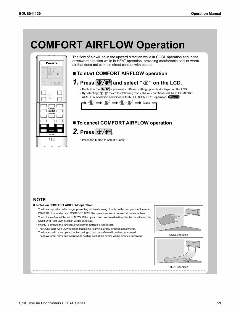
EDUS041129 Operation Manual
COMFORT AIRFLOW OperationThe fl ow of air will be in the upward direction while in COOL operation and in the downward direction while in HEAT operation, comfortable
come in direct contact with people.
To start COMFORT AIRFLOW operation
Press1. and select “ ” on the LCD.Each time the • is pressed a different setting option is displayed on the LCD.By selecting “ • ” from the following icons, the air conditioner will be in COMFORT AIRFLOW operation combined with INTELLIGENT EYE operation. Page 16
Blank
To cancel COMFORT AIRFLOW operation
Press2. .Press the button to select “Blank”.•
NOTENotes on COMFORT AIRFLOW operation
The louvers position will change, preventing air from blowing directly on the occupants of the room.•POWERFUL operation and COMFORT AIRFLOW operation cannot be used at the same time.•The volume of air will be set to AUTO. If the upward and downward airfl ow direction is selected, the •COMFORT AIRFLOW function will be canceled.Priority is given to the function of whichever button is pressed last.•The COMFORT AIRFLOW function makes the following airfl ow direction adjustments.•The louvers will move upward while cooling so that the airfl ow will be directed upward.The louvers will move downward while heating so that the airfl ow will be directed downward. COOL operation
HEAT operation
Split Type Air Conditioners FTXS-L Series 59
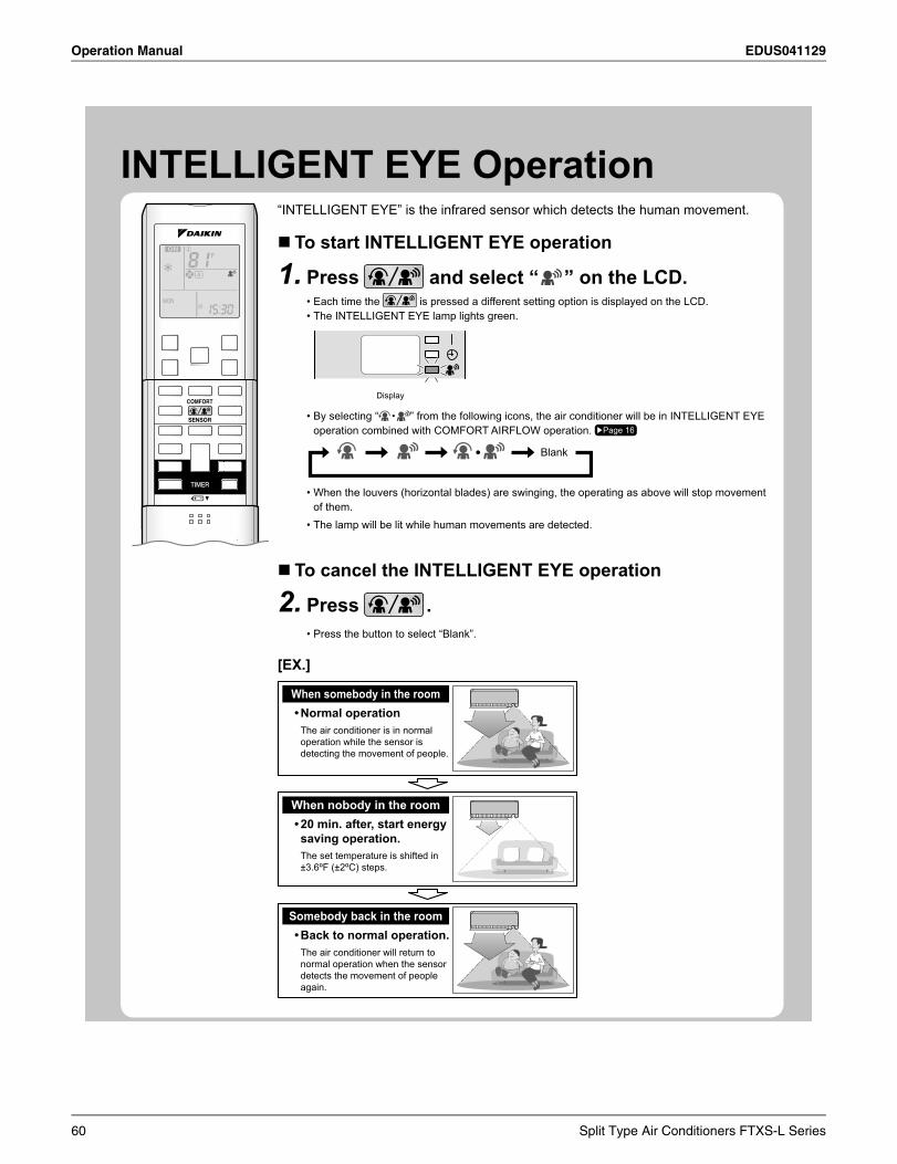
Operation Manual EDUS041129
INTELLIGENT EYE Operation“INTELLIGENT EYE” is the infrared sensor which detects the human movement.
To start INTELLIGENT EYE operation
Press1. and select “ ” on the LCD.Each time the • is pressed a different setting option is displayed on the LCD.The INTELLIGENT EYE lamp lights green.•
Display
By selecting “• ” from the following icons, the air conditioner will be in INTELLIGENT EYE operation combined with COMFORT AIRFLOW operation. Page 16
Blank
When the louvers (horizontal blades) are swinging, the operating as above will stop movement •of them.The lamp will be lit while human movements are detected.•
To cancel the INTELLIGENT EYE operation
Press2. .Press the button to select “Blank”.•
[EX.]
Somebody back in the room • Back to normal operation.
The air conditioner will return to normal operation when the sensor detects the movement of people again.
When somebody in the room • Normal operation
The air conditioner is in normal operation while the sensor is detecting the movement of people.
When nobody in the room • 20 min. after, start energy
saving operation.The set temperature is shifted in ±3.6ºF (±2ºC) steps.
60 Split Type Air Conditioners FTXS-L Series
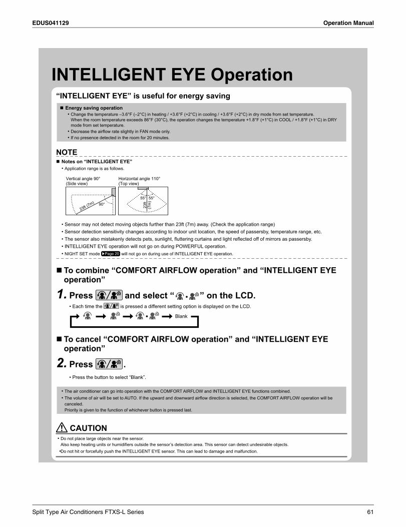
EDUS041129 Operation Manual
INTELLIGENT EYE Operation“INTELLIGENT EYE” is useful for energy saving
Energy saving operationChange the temperature –3.6°F (–2°C) in heating / +3.6°F (+2°C) in cooling / +3.6°F (+2°C) in dry mode from set temperature.•When the room temperature exceeds 86°F (30°C), the operation changes the temperature +1.8°F (+1°C) in COOL / +1.8°F (+1°C) in DRYmode from set temperature.Decrease the airfl ow rate slightly in FAN mode only.•If no presence detected in the room for 20 minutes.•
NOTENotes on “INTELLIGENT EYE”
Application range is as follows.•
90°55°
23ft
(7m
)
55°
Vertical angle 90°(Side view)
Horizontal angle 110°(Top view)
23ft (7m)
Sensor may not detect moving objects further than 23ft (7m) away. (Check the application range)•Sensor detection sensitivity changes according to indoor unit location, the speed of passersby, temperature range, etc.•The sensor also mistakenly detects pets, sunlight, fl uttering curtains and light refl ected off of mirrors as passersby.•INTELLIGENT EYE operation will not go on during POWERFUL operation.•NIGHT SET mode • Page 20 will not go on during use of INTELLIGENT EYE operation.
To combine “COMFORT AIRFLOW operation” and “INTELLIGENT EYE operation”
Press1. and select “ ” on the LCD.Each time the • is pressed a different setting option is displayed on the LCD.
Blank
To cancel “COMFORT AIRFLOW operation” and “INTELLIGENT EYE operation”
Press2. .Press the button to select “Blank”.•
The air conditioner can go into operation with the COMFORT AIRFLOW and INTELLIGENT EYE functions combined.•The volume of air will be set to AUTO. If the upward and downward airfl ow direction is selected, the COMFORT AIRFLOW operation will be •canceled.Priority is given to the function of whichever button is pressed last.
CAUTIONDo not place large objects near the sensor.•Also keep heating units or humidifi ers outside the sensor’s detection area. This sensor can detect undesirable objects.Do not hit or push the INTELLIGENT EYE sensor. This can lead to damage and malfunction.•
Split Type Air Conditioners FTXS-L Series 61
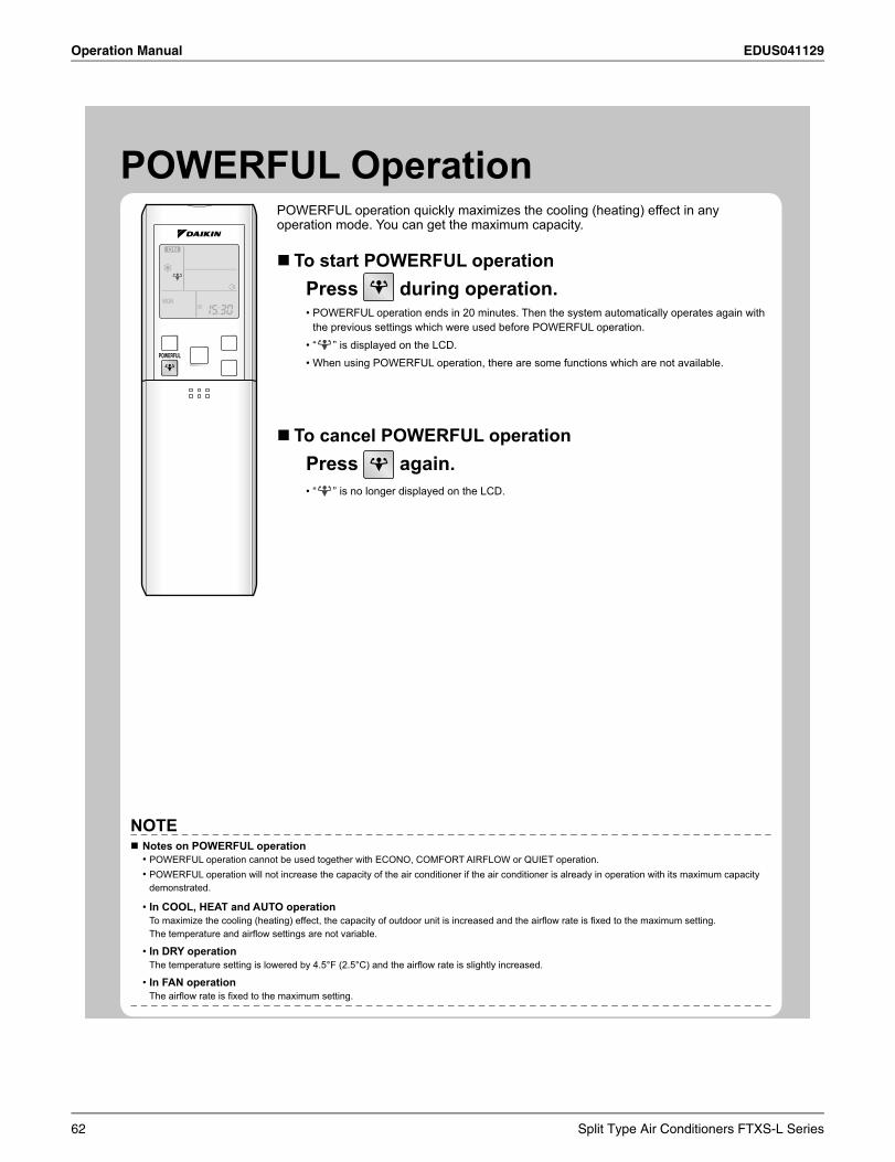
Operation Manual EDUS041129
POWERFUL OperationPOWERFUL operation quickly maximizes the cooling (heating) effect in any operation mode. You can get the maximum capacity.
To start POWERFUL operationPress during operation.
POWERFUL operation ends in 20 minutes. Then the system automatically operates again with •the previous settings which were used before POWERFUL operation.“ • ” is displayed on the LCD.When using POWERFUL operation, there are some functions which are not available.•
To cancel POWERFUL operationPress again.
“ • ” is no longer displayed on the LCD.
NOTENotes on POWERFUL operation
POWERFUL operation cannot be used together with ECONO, COMFORT AIRFLOW or QUIET operation.•POWERFUL operation will not increase the capacity of the air conditioner if the air conditioner is already in operation with its maximum capacity •demonstrated.
In COOL, HEAT and AUTO operation•To maximize the cooling (heating) effect, the capacity of outdoor unit is increased and the airfl ow rate is fi xed to the maximum setting.The temperature and airfl ow settings are not variable.
In DRY operation•The temperature setting is lowered by 4.5°F (2.5°C) and the airfl ow rate is slightly increased.
In FAN operation•The airfl ow rate is fi xed to the maximum setting.
62 Split Type Air Conditioners FTXS-L Series
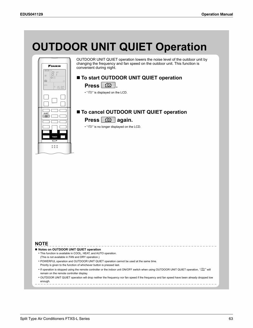
EDUS041129 Operation Manual
18
OUTDOOR UNIT QUIET OperationOUTDOOR UNIT QUIET operation lowers the noise level of the outdoor unit by changing the frequency and fan speed on the outdoor unit. This function is convenient during night.
To start OUTDOOR UNIT QUIET operationPress .
“• ” is displayed on the LCD.
To cancel OUTDOOR UNIT QUIET operationPress again.
“• ” is no longer displayed on the LCD.
NOTENotes on OUTDOOR UNIT QUIET operation
This function is available in COOL, HEAT, and AUTO operation.•(This is not available in FAN and DRY operation.)POWERFUL operation and OUTDOOR UNIT QUIET operation cannot be used at the same time.•Priority is given to the function of whichever button is pressed last.
If operation is stopped using the remote controller or the indoor unit ON/OFF switch when using OUTDOOR UNIT QUIET operation, “• ” will remain on the remote controller display.OUTDOOR UNIT QUIET operation will drop neither the frequency nor fan speed if the frequency and fan speed have been already dropped low •enough.
Split Type Air Conditioners FTXS-L Series 63
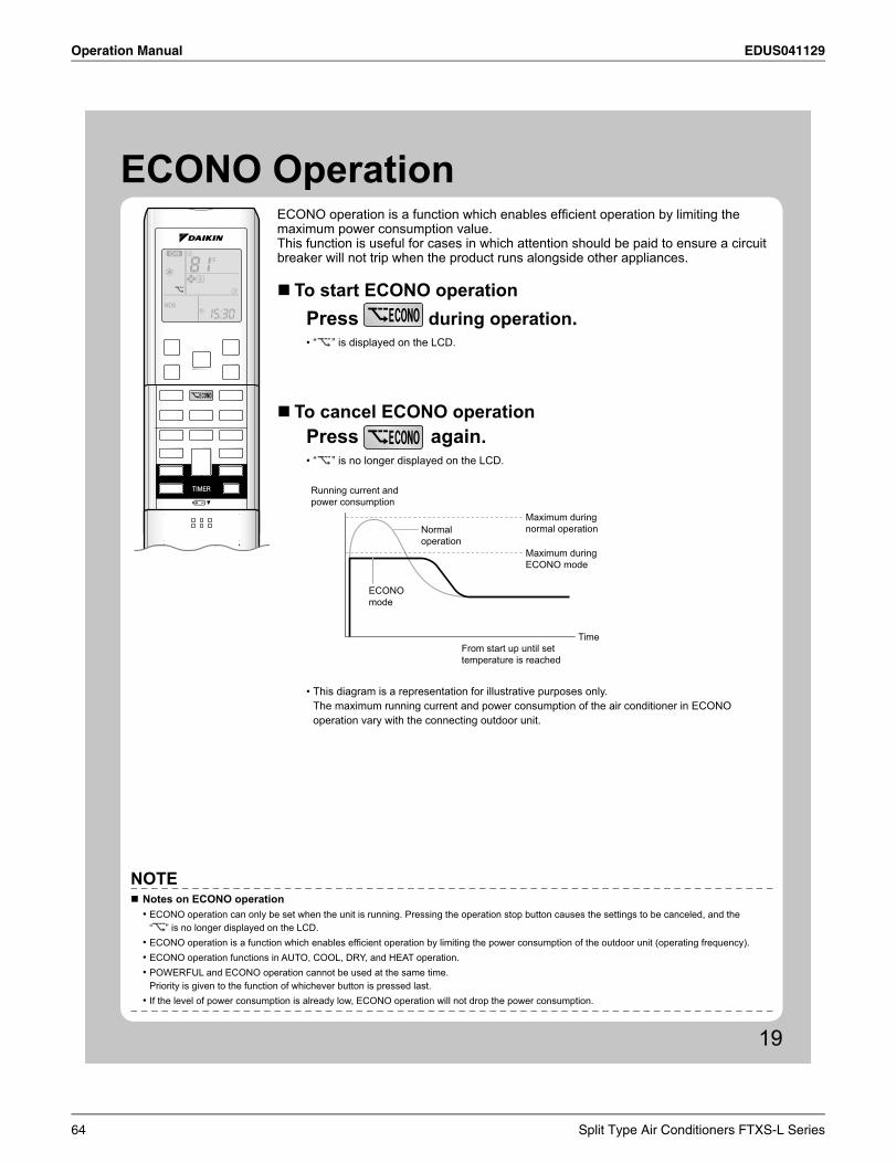
Operation Manual EDUS041129
19
ECONO OperationECONO operation is a function which enables effi cient operation by limiting the maximum power consumption value.This function is useful for cases in which attention should be paid to ensure a circuit breaker will not trip when the product runs alongside other appliances.
To start ECONO operationPress during operation.
“• ” is displayed on the LCD.
To cancel ECONO operationPress again.
“• ” is no longer displayed on the LCD.
Running current and power consumption
From start up until set temperature is reached
Time
Maximum during normal operation
Maximum during ECONO mode
Normaloperation
ECONOmode
This diagram is a representation for illustrative purposes only. •The maximum running current and power consumption of the air conditioner in ECONO operation vary with the connecting outdoor unit.
NOTENotes on ECONO operation
ECONO operation can only be set when the unit is running. Pressing the operation stop button causes the settings to be canceled, and the •“ ” is no longer displayed on the LCD.ECONO operation is a function which enables effi cient operation by limiting the power consumption of the outdoor unit (operating frequency).•ECONO operation functions in AUTO, COOL, DRY, and HEAT operation. •POWERFUL and ECONO operation cannot be used at the same time.•Priority is given to the function of whichever button is pressed last. If the level of power consumption is already low, ECONO operation will not drop the power consumption.•
64 Split Type Air Conditioners FTXS-L Series
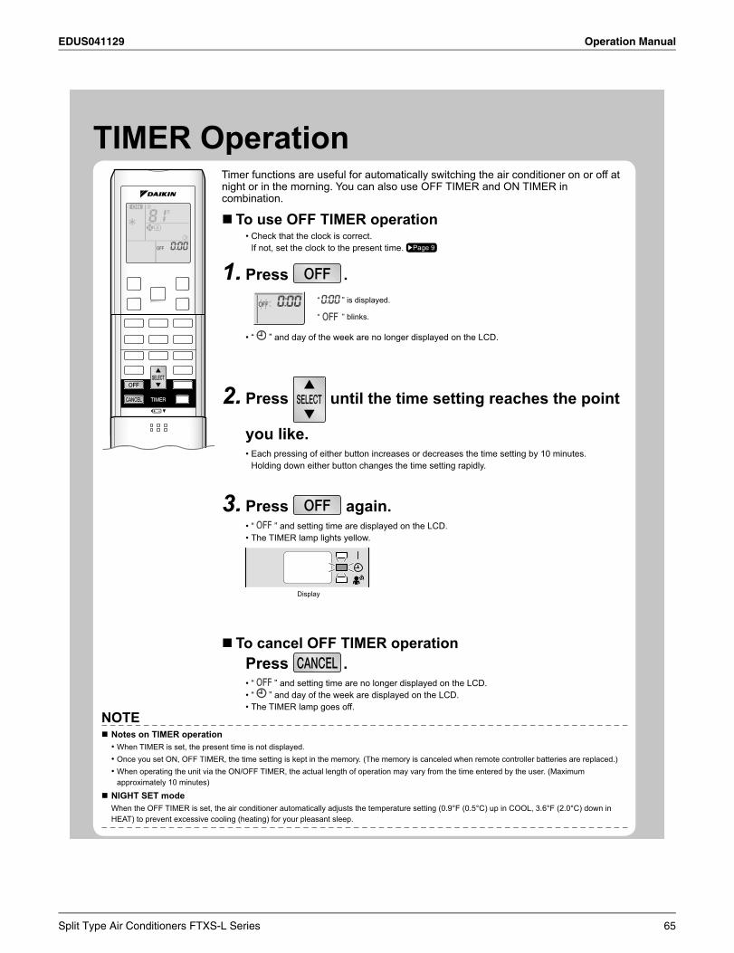
EDUS041129 Operation Manual
TIMER OperationTimer functions are useful for automatically switching the air conditioner on or off at night or in the morning. You can also use OFF TIMER and ON TIMER in combination.
To use OFF TIMER operationCheck that the clock is correct.•If not, set the clock to the present time. Page 9
Press1. .” is displayed.
” blinks.
“
“
“ • ” and day of the week are no longer displayed on the LCD.
Press2. until the time setting reaches the point
you like.Each pressing of either button increases or decreases the time setting by 10 minutes. •Holding down either button changes the time setting rapidly.
Press3. again.“ • ” and setting time are displayed on the LCD.The TIMER lamp lights yellow.•
Display
To cancel OFF TIMER operationPress .
“ • ” and setting time are no longer displayed on the LCD.“ • ” and day of the week are displayed on the LCD.The TIMER lamp goes off.•
NOTENotes on TIMER operation
When TIMER is set, the present time is not displayed.•Once you set ON, OFF TIMER, the time setting is kept in the memory. (The memory is canceled when remote controller batteries are replaced.)•When operating the unit via the ON/OFF TIMER, the actual length of operation may vary from the time entered by the user. (Maximum •approximately 10 minutes)
NIGHT SET modeWhen the OFF TIMER is set, the air conditioner automatically adjusts the temperature setting (0.9°F (0.5°C) up in COOL, 3.6°F (2.0°C) down in HEAT) to prevent excessive cooling (heating) for your pleasant sleep.
Split Type Air Conditioners FTXS-L Series 65
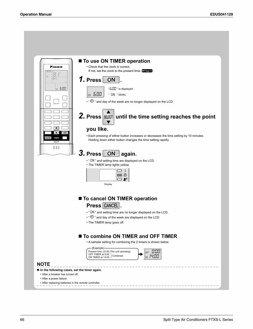
Operation Manual EDUS041129
To use ON TIMER operationCheck that the clock is correct.•If not, set the clock to the present time. Page 9
Press1. .” is displayed.
” blinks.
“
“
“ • ” and day of the week are no longer displayed on the LCD.
Press2. until the time setting reaches the point
you like.Each pressing of either button increases or decreases the time setting by 10 minutes. •Holding down either button changes the time setting rapidly.
Press3. again.“ • ” and setting time are displayed on the LCD.The TIMER lamp lights yellow.•
Display
To cancel ON TIMER operationPress .
“ • ” and setting time are no longer displayed on the LCD.“ • ” and day of the week are displayed on the LCD.The TIMER lamp goes off.•
To combine ON TIMER and OFF TIMERA sample setting for combining the 2 timers is shown below.•
(Example)Present time: 23:00 (The unit operating)OFF TIMER at 0:00ON TIMER at 14:00 Combined
NOTEIn the following cases, set the timer again.
After a breaker has turned off.•After a power failure.•After replacing batteries in the remote controller.•
66 Split Type Air Conditioners FTXS-L Series
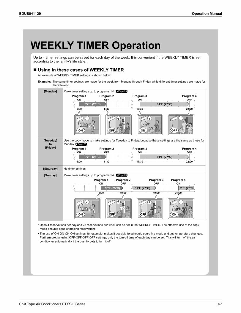
EDUS041129 Operation Manual
WEEKLY TIMER OperationUp to 4 timer settings can be saved for each day of the week. It is convenient if the WEEKLY TIMER is set according to the family’s life style.
Using in these cases of WEEKLY TIMERAn example of WEEKLY TIMER settings is shown below.
Example: The same timer settings are made for the week from Monday through Friday while different timer settings are made for the weekend.
[Monday] Make timer settings up to programs 1-4. Page 23
6:00 8:30 17:30 22:00
77°F (25°C) 81°F (27°C)
Program 1 Program 2 Program 3 Program 4ON OFF ON OFF
27�C25�C
ON ON OFFOFF
[Tuesday]to
[Friday]
Use the copy mode to make settings for Tuesday to Friday, because these settings are the same as those for Monday. Page 25
6:00 8:30 17:30 22:00
77°F (25°C) 81°F (27°C)
Program 1 Program 2 Program 3 Program 4ON OFF ON OFF
[Saturday] No timer settings
[Sunday] Make timer settings up to programs 1-4. Page 23
8:00 10:00 19:00 21:00
81°F (27°C) 81°F (27°C)77°F (25°C)ON OFF OFF ON
Program 1 Program 2 Program 3 Program 4
27�C25�C
ON ONOFFOFF
Up to 4 reservations per day and 28 reservations per week can be set in the WEEKLY TIMER. The effective use of the copy •mode ensures ease of making reservations. The use of ON-ON-ON-ON settings, for example, makes it possible to schedule operating mode and set temperature changes. •Furthermore, by using OFF-OFF-OFF-OFF settings, only the turn-off time of each day can be set. This will turn off the air conditioner automatically if the user forgets to turn it off.
Split Type Air Conditioners FTXS-L Series 67
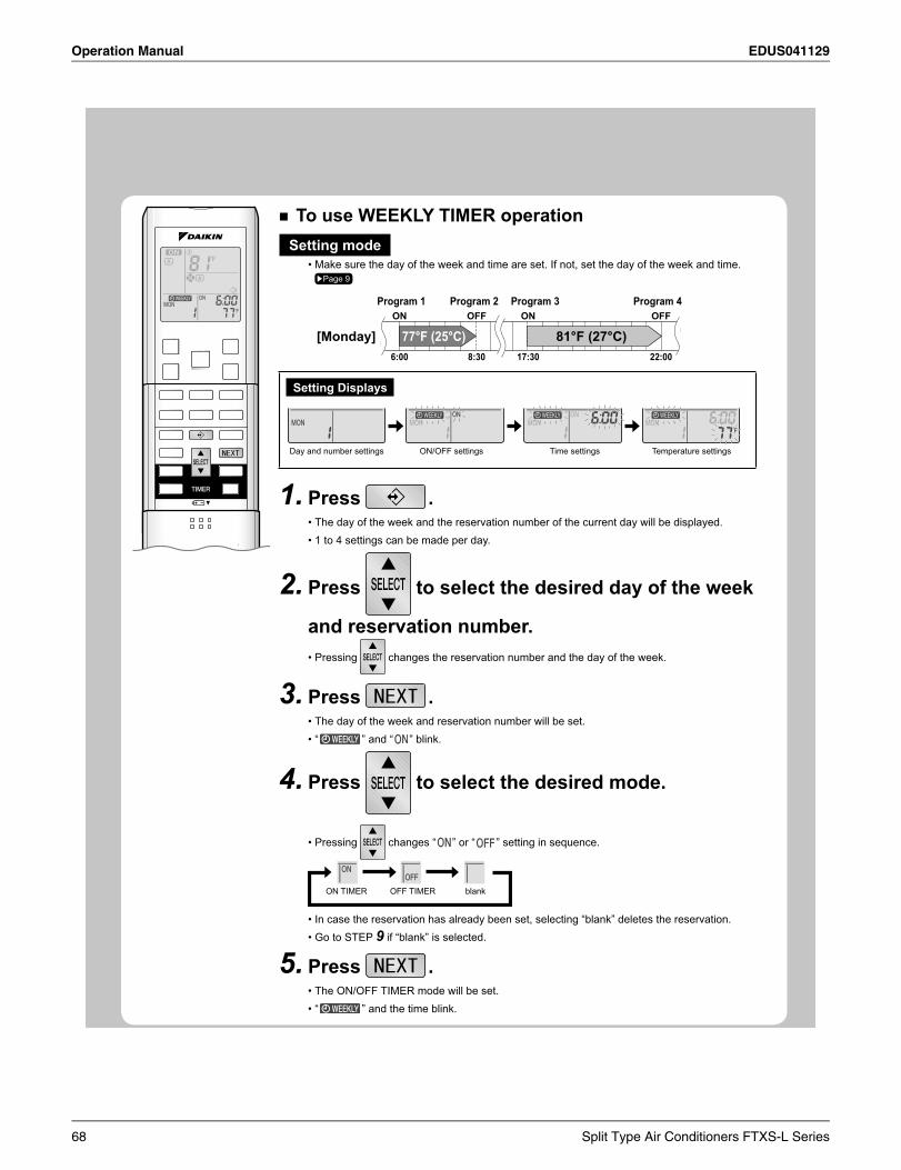
Operation Manual EDUS041129
To use WEEKLY TIMER operationSetting mode
Make sure the day of the week and time are set. If not, set the day of the week and time.•Page 9
6:00 8:30 17:30 22:00
77°F (25°C) 81°F (27°C)
Program 1 Program 2 Program 3 Program 4ON OFF ON OFF
[Monday]
Setting Displays
Day and number settings ON/OFF settings Time settings Temperature settings
Press1. .The day of the week and the reservation number of the current day will be displayed.•1 to 4 settings can be made per day. •
Pr2. ess to select the desired day of the week
and reservation number.Pressing • changes the reservation number and the day of the week.
Press3. .The day of the week and reservation number will be set.•“ • ” and “ ” blink.
Press4. to select the desired mode.
Pressing • changes “ ” or “ ” setting in sequence.
ON TIMER OFF TIMER blank
In case the reservation has already been set, selecting “blank” deletes the reservation.•Go to STEP • 9 if “blank” is selected.
P5. ress .The ON/OFF TIMER mode will be set.•“ • ” and the time blink.
68 Split Type Air Conditioners FTXS-L Series
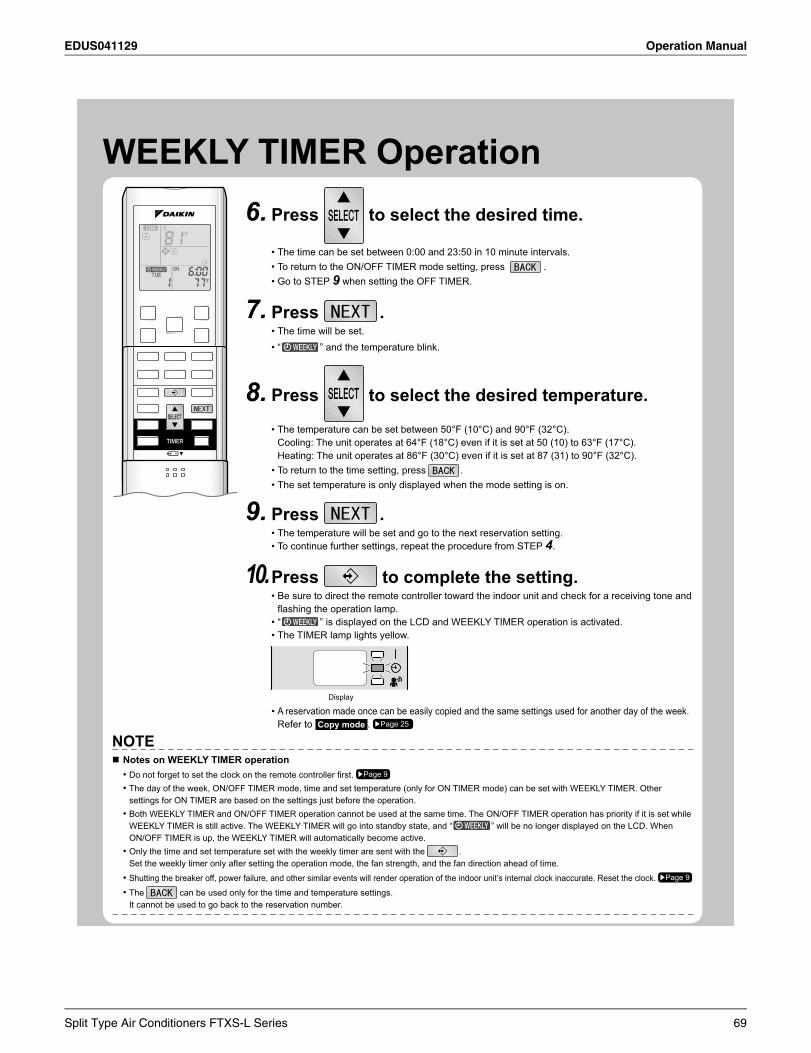
EDUS041129 Operation Manual
WEEKLY TIMER Operation6. Press to select the desired time.
The time can be set between 0:00 and 23:50 in 10 minute intervals. •To return to the ON/OFF TIMER mode setting, press • .Go to STEP • 9 when setting the OFF TIMER.
Press7. .The time will be set. •“ • ” and the temperature blink.
Press8. to select the desired temperature.
The temperature can be set between 50°F (10°C) and 90°F (32°C).•Cooling: The unit operates at 64°F (18°C) even if it is set at 50 (10) to 63°F (17°C).Heating: The unit operates at 86°F (30°C) even if it is set at 87 (31) to 90°F (32°C).To return to the time setting, press • .The set temperature is only displayed when the mode setting is on.•
Press9. .The temperature will be set and go to the next reservation setting.•To continue further settings, repeat the procedure from STEP • 4.
Press10. to complete the setting. Be sure to direct the remote controller toward the indoor unit and check for a receiving tone and •fl ashing the operation lamp.“ • ” is displayed on the LCD and WEEKLY TIMER operation is activated.The TIMER lamp lights yellow.•
Display
A reservation made once can be easily copied and the same settings used for another day of the week. •Refer to Copy mode . Page 25
NOTENotes on WEEKLY TIMER operation
Do not forget to set the clock on the remote controller fi rst. • Page 9
The day of the week, ON/OFF TIMER mode, time and set temperature (only for ON TIMER mode) can be set with WEEKLY TIMER. Other •settings for ON TIMER are based on the settings just before the operation.Both WEEKLY TIMER and ON/OFF TIMER operation cannot be used at the same time. The ON/OFF TIMER operation has priority if it is set while •WEEKLY TIMER is still active. The WEEKLY TIMER will go into standby state, and “ ” will be no longer displayed on the LCD. When ON/OFF TIMER is up, the WEEKLY TIMER will automatically become active.Only the time and set temperature set with the weekly timer are sent with the • .Set the weekly timer only after setting the operation mode, the fan strength, and the fan direction ahead of time.
Shutting the breaker off, power failure, and other similar events will render operation of the indoor unit’s internal clock inaccurate. Reset the clock. • Page 9
The• can be used only for the time and temperature settings.It cannot be used to go back to the reservation number.
Split Type Air Conditioners FTXS-L Series 69
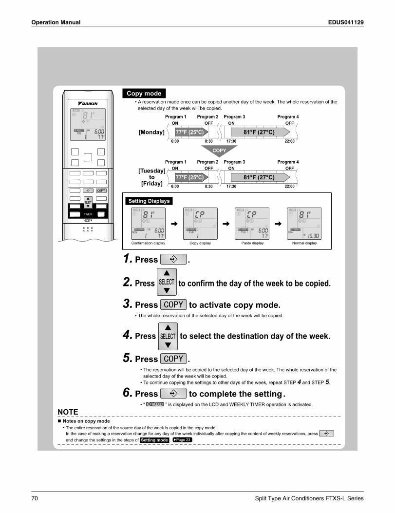
Operation Manual EDUS041129
Copy modeA reservation made once can be copied another day of the week. The whole reservation of the •selected day of the week will be copied.
6:00 8:30 17:30 22:00
77°F (25°C) 81°F (27°C)
6:00 8:30 17:30 22:00
77°F (25°C) 81°F (27°C)
COPY
Program 1 Program 2 Program 3 Program 4ON OFF ON OFF
[Monday]
Program 1 Program 2 Program 3 Program 4ON OFF ON OFF[Tuesday]
to [Friday]
Setting Displays
Confirmation display Copy display Paste display Normal display
Press1. .
Press2. to confi rm the day of the week to be copied.
Press3. to activate copy mode.The whole reservation of the selected day of the week will be copied.•
Press4. to select the destination day of the week.
Press5. .The reservation will be copied to the selected day of the week. The whole reservation of the •selected day of the week will be copied. To continue copying the settings to other days of the week, repeat STEP • 4 and STEP 5.
Press6. to complete the setting .“ • ” is displayed on the LCD and WEEKLY TIMER operation is activated.
NOTENotes on copy mode
The entire reservation of the source day of the week is copied in the copy mode.•In the case of making a reservation change for any day of the week individually after copying the content of weekly reservations, press and change the settings in the steps of Setting mode . Page 23
70 Split Type Air Conditioners FTXS-L Series
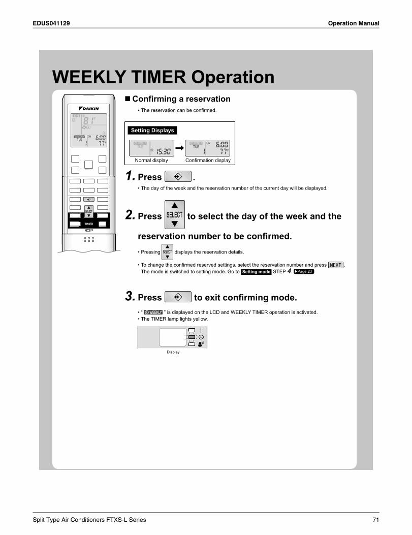
EDUS041129 Operation Manual
WEEKLY TIMER OperationConfi rming a reservation
The reservation can be confi rmed.•
Setting Displays
Normal display Confi rmation display
Press1. .The day of the week and the reservation number of the current day will be displayed.•
Press2. to select the day of the week and the
reservation number to be confi rmed.Pressing • displays the reservation details.
To change the confi rmed reserved settings, select the reservation number and press • .The mode is switched to setting mode. Go to Setting mode STEP 4. Page 23
Press3. to exit confi rming mode.“ • ” is displayed on the LCD and WEEKLY TIMER operation is activated.The TIMER lamp lights yellow.•
Display
Split Type Air Conditioners FTXS-L Series 71
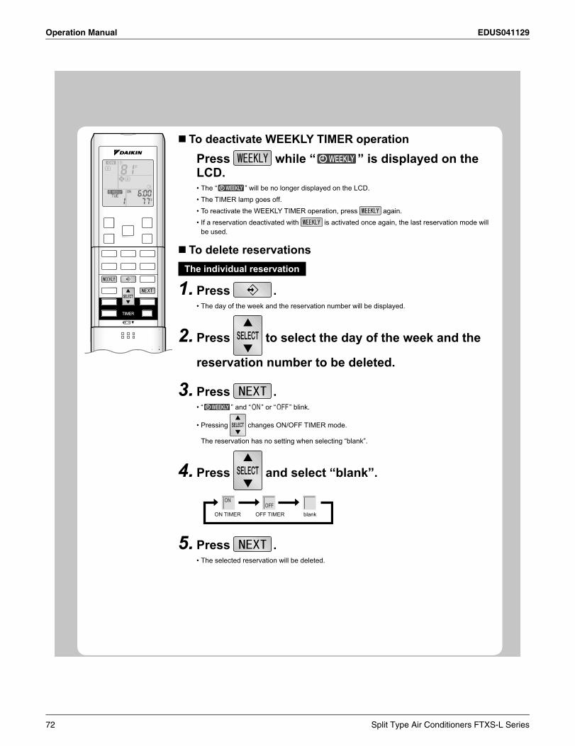
Operation Manual EDUS041129
To deactivate WEEKLY TIMER operationPress while “ ” is displayed on the LCD.
The “ • ” will be no longer displayed on the LCD.The TIMER lamp goes off.•To reactivate the WEEKLY TIMER operation, press • again.If a reservation deactivated with • is activated once again, the last reservation mode will be used.
To delete reservationsThe individual reservation
Press1. .The day of the week and the reservation number will be displayed.•
Press2. to select the day of the week and the
reservation number to be deleted.
Press3. .“ • ” and “ ” or “ ” blink.
Pressing • changes ON/OFF TIMER mod
eservation selecting “blank”.
Press4. and select “blank”.
ON TIMER OFF TIMER blank
Press5. .The selected reservation will be deleted.•
72 Split Type Air Conditioners FTXS-L Series
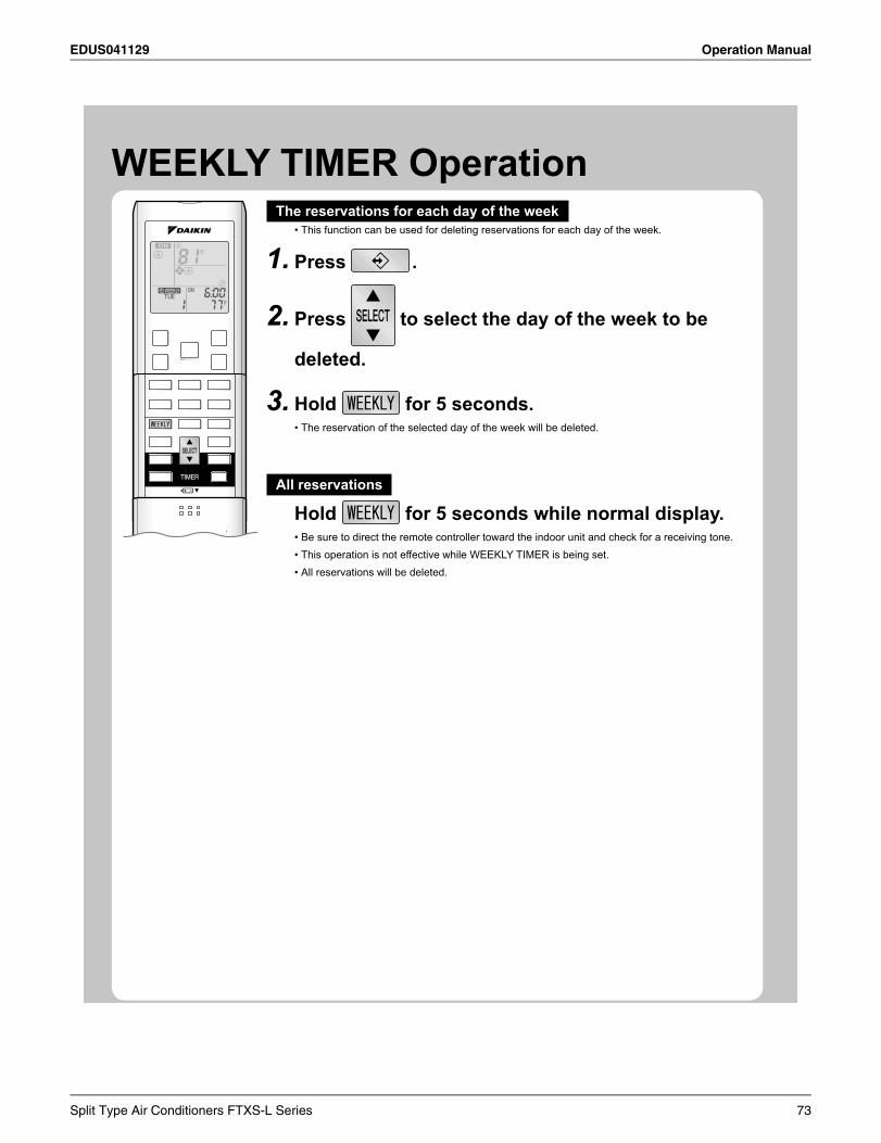
EDUS041129 Operation Manual
WEEKLY TIMER OperationThe reservations for each day of the week
This function can be used for deleting reservations for each day of the week.•
Press1. .
Press2. to select the day of the week to be
deleted.
Hold3. for 5 seconds.The reservation of the selected day of the week will be deleted.•
All reservations
Hold for 5 seconds while normal display.Be sure to direct the remote controller toward the indoor unit and check for a receiving tone.•This operation is not effective while WEEKLY TIMER is being set.•All reservations will be deleted.•
Split Type Air Conditioners FTXS-L Series 73
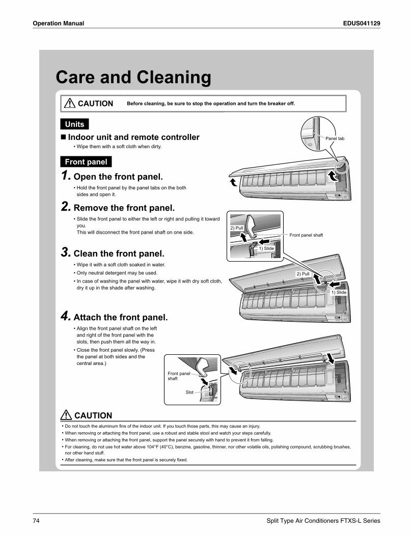
Operation Manual EDUS041129
Care and Cleaning CAUTION Before cleaning, be sure to stop the operation and turn the breaker off.
UnitsIndoor unit and remote controller
Wipe them with a soft cloth when dirty.•
Front panel
Open the front panel.1.Hold the front panel by the panel tabs on the both •sides and open it.
Remove the front panel. 2.Slide the front panel to either the left or right and pulling it toward •you.This will disconnect the front panel shaft on one side.
Clean the front panel.3.Wipe it with a soft cloth soaked in water.•Only neutral detergent may be used.•In case of washing the panel with water, wipe it with dry soft cloth, •dry it up in the shade after washing.
Attach the front panel.4.Align the front panel shaft on the left •and right of the front panel with the slots, then push them all the way in.Close the front panel slowly. (Press •the panel at both sides and the central area.)
Panel tab
1) Slide
2) Pull
Front panel shaft
1) Slide
2) Pull
Front panel shaft
Slot
CAUTIONDo not touch the aluminum fi ns of the indoor unit. If you touch those parts, this may cause an injury.•When removing or attaching the front panel, use a robust and stable stool and watch your steps carefully.•When removing or attaching the front panel, support the panel securely with hand to prevent it from falling.•For cleaning, do not use hot water above 104°F (40°C), benzine, gasoline, thinner, nor other volatile oils, polishing compound, scrubbing brushes, •nor other hand stuff.After cleaning, make sure that the front panel is securely fi xed.•
74 Split Type Air Conditioners FTXS-L Series
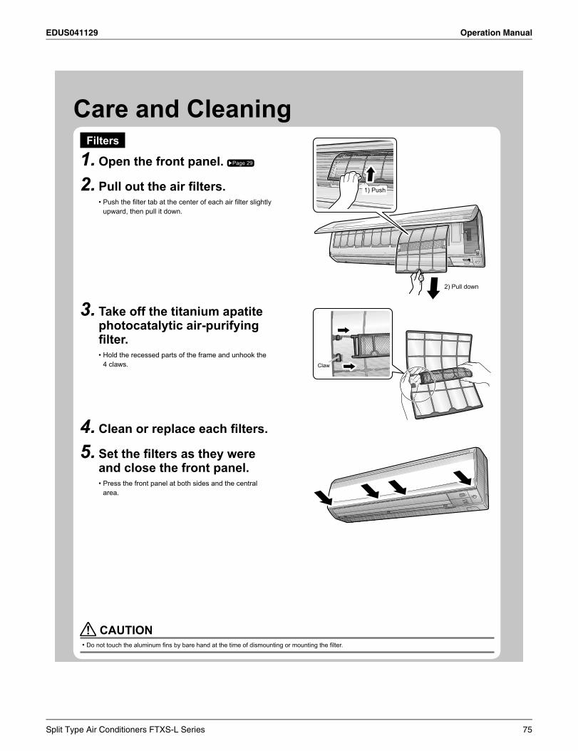
EDUS041129 Operation Manual
Care and CleaningFilters
Open the front panel. 1. Page 29
Pull out the air fi lters. 2.Push the fi lter tab at the center of each air fi lter slightly •upward, then pull it down.
Take off the titanium apatite 3.photocatalytic air-purifying fi lter.
Hold the recessed parts of the frame and unhook the •4 claws.
Clean or replace each fi lters.4.Set the fi lters as they were 5.and close the front panel.
Press the front panel at both sides and the central •area.
2) Pull down
1) Push
ClawClaw
CAUTIONDo not touch the aluminum fi ns by bare hand at the time of dismounting or mounting the fi lter.•
Split Type Air Conditioners FTXS-L Series 75
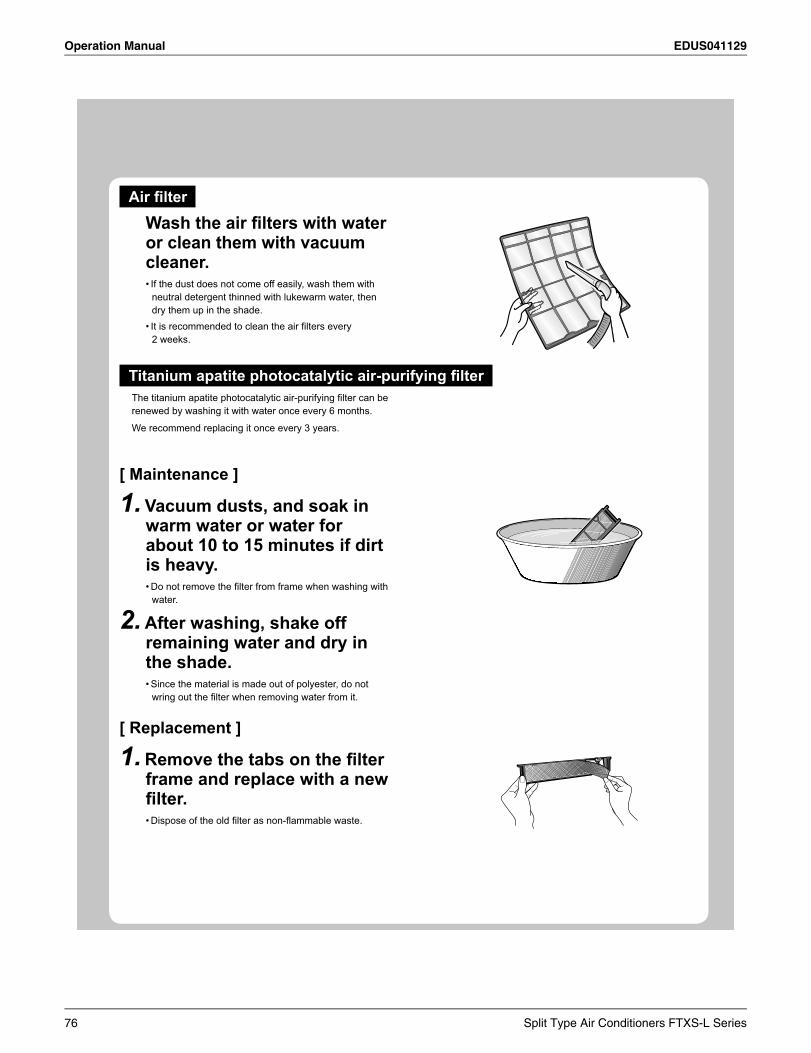
Operation Manual EDUS041129
Air fi lter
Wash the air fi lters with water or clean them with vacuum cleaner. If the dust does not come off easily, wash them with •neutral detergent thinned with lukewarm water, then dry them up in the shade.It is recommended to clean the air fi lters every •2 weeks.
Titanium apatite photocatalytic air-purifying fi lterThe titanium apatite photocatalytic air-purifying fi lter can be renewed by washing it with water once every 6 months.
We recommend replacing it once every 3 years.
[ Maintenance ]
Vacuum dusts, and soak in 1.warm water or water for about 10 to 15 minutes if dirt is heavy. Do not remove the fi lter from frame when washing with •water.
After washing, shake off 2.remaining water and dry in the shade.Since the material is made out of polyester, do not •wring out the fi lter when removing water from it.
[ Replacement ]
Remove the tabs on the fi lter 1.frame and replace with a new fi lter. Dispose of the old fi lter as non-fl ammable waste.•
76 Split Type Air Conditioners FTXS-L Series
EDUS041129 Operation Manual
Care and CleaningNOTE
Operation with dirty fi lters:•cannot deodorize the air.1)cannot clean the air.2)results in poor heating or cooling.3)may cause odor.4)
To order titanium apatite photocatalytic air-purifying fi lter contact to the service shop there you purchased the air conditioner.•Dispose of old fi lters as non-fl ammable waste. •
Item Part No.Titanium apatite photocatalytic air-purifying fi lter (without frame) 1 set KAF970A48
ATTENTIONDo not throw away the fi lter frame. Reuse the fi lter frame when replacing the titanium apatite photocatalytic air-purifying fi lter.•
CHECKCheck that the base, stand and other fi ttings of the outdoor unit are not decayed or corroded.Check that nothing blocks the air inlets and the outlets of the indoor unit and the outdoor unit.Check that the drain comes smoothly out of the drain hose during COOL or DRY operation.
If no drain water is seen, water may be leaking from the indoor unit. Stop operation and consult the service shop if this is the •case.
Before a long idle period.
Operate the “FAN only” for several hours on a nice day to dry out 1.the inside.
Press • and select “ ” operation.
Press • and start the operation.
After operation stops, turn off the breaker for the room air 2.conditioner.Clean the air fi lters and set them again.3.Take out batteries from the remote controller.4.
Split Type Air Conditioners FTXS-L Series 77
Operation Manual EDUS041129
TroubleshootingThese cases are not troubles.
The following cases are not air conditioner troubles but have some reasons. You may just continue using it.
Case Explanation
Operation does not start soon.When ON/OFF button was pressed soon after •operation was stopped.When the mode was reselected.•
This is to protect the air conditioner.•You should wait for about 3 minutes.
Hot air does not fl ow out soon after the start of heating operation.
The air conditioner is warming up. You should wait for 1 to 4 minutes.•(The system is designed to start discharging air only after it has reached a certain temperature.)
The HEAT operation stops suddenly and a fl owing sound is heard.
The outdoor unit is taking away the frost. The HEAT operation starts after the frost on the •outdoor unit is removed. You should wait for about 4 to 12 minutes.
Possible sounds.
Flowing waterGenerated because the refrigerant in the air conditioner is fl owing.•This is a pumping sound of the water in the air conditioner it is heard when the water is •pumped out from the air conditioner in cooling or drying operation.The refrigerant fl ows in the air conditioner even if the air conditioner is not working when •the indoor units in other rooms are in operation.
BlowingGenerated when the fl ow of the refrigerant in the air conditioner is switched over.•
TickingGenerated when the size of the air conditioner slightly expands or shrinks as a result of •temperature changes.
WhistlingGenerated when refrigerant fl ows during defrosting operation.•
ClickingGenerated when the refrigerant control valves or the electrical parts operate.•
CloppingHeard from the inside of the air conditioner when the exhaust fan is activated while the •room doors are closed. Open the window or turn off the exhaust fan.
The outdoor unit emits water or steam.
In HEAT operationThe frost on the outdoor unit melts into water or steam when the air conditioner is in •defrost operation.
In COOL or DRY operationMoisture in the air condenses into water on the cool surface of outdoor unit piping and drips.•
Mist comes out of the indoor unit.
This happens when the air in the room is cooled into mist by the cold airfl ow during cooling operation.This is because the air in the room is cooled by the heat exchanger and becomes mist during defrost operation.
The indoor unit gives out odor.
This happens when smells of the room, furniture, or cigarettes are absorbed into the unit and discharged with the airfl ow. If this happens, have the indoor unit washed by a technician from the service shop where you purchased the air conditioner.
78 Split Type Air Conditioners FTXS-L Series
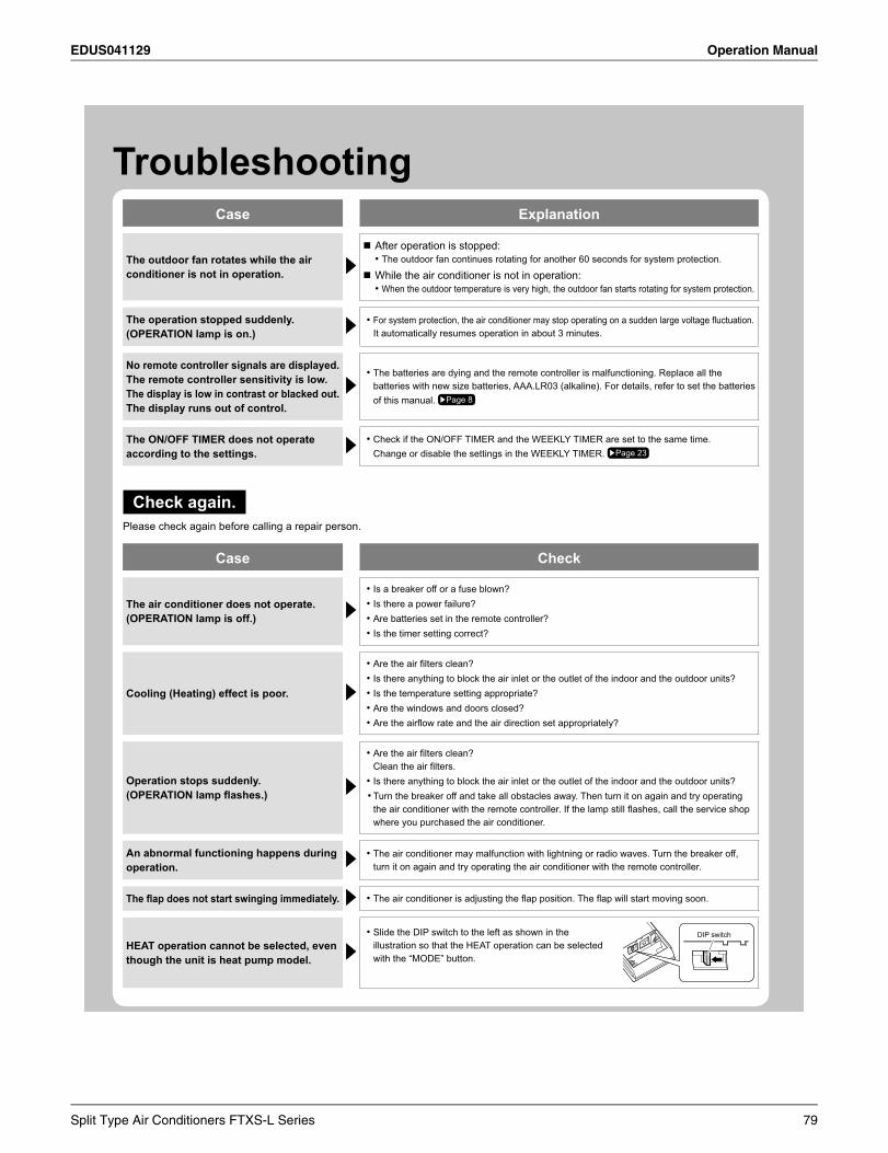
EDUS041129 Operation Manual
TroubleshootingCase Explanation
The outdoor fan rotates while the air conditioner is not in operation.
After operation is stopped:The outdoor fan continues rotating for another 60 seconds for system protection.•
While the air conditioner is not in operation:When the outdoor temperature is very high, the outdoor fan starts rotating for system protection.•
The operation stopped suddenly.(OPERATION lamp is on.)
For system protection, the air conditioner may stop operating on a sudden large voltage fl uctuation.•It automatically resumes operation in about 3 minutes.
No remote controller signals are displayed.The remote controller sensitivity is low.The display is low in contrast or blacked out.The display runs out of control.
The batteries are dying and the remote controller is malfunctioning. Replace all the •batteries with new size batteries, AAA.LR03 (alkaline). For details, refer to set the batteries of this manual. Page 8
The ON/OFF TIMER does not operate according to the settings.
Check if the ON/OFF TIMER and the WEEKLY TIMER are set to the same time.•Change or disable the settings in the WEEKLY TIMER. Page 23
Check again.Please check again before calling a repair person.
Case Check
The air conditioner does not operate.(OPERATION lamp is off.)
Is a breaker off or a fuse blown? •Is there a power failure? •Are batteries set in the remote controller?•Is the timer setting correct?•
Cooling (Heating) effect is poor.
Are the air fi lters clean?•Is there anything to block the air inlet or the outlet of the indoor and the outdoor units?•Is the temperature setting appropriate?•Are the windows and doors closed?•Are the airfl ow rate and the air direction set appropriately?•
Operation stops suddenly.(OPERATION lamp fl ashes.)
Are the air fi lters clean?•Clean the air fi lters. Is there anything to block the air inlet or the outlet of the indoor and the outdoor units? •Turn the b eaker off and take all obstacles away. Then turn it on again and try operating •the air conditioner with the remote controller. If the lamp still fl ashes, call the service shop where you purchased the air conditioner.
An abnormal functioning happens during operation.
The air conditioner may malfunction with lightning or radio waves. Turn the breaker off, •turn it on again and try operating the air conditioner with the remote controller.
The fl ap does not start swinging immediately. The air conditioner is adjusting the fl ap position. The fl ap will start moving soon.•
HEAT operation cannot be selected, even though the unit is heat pump model.
Slide the DIP switch to the left as shown in the •illustration so that the HEAT operation can be selected with the “MODE” button.
DIP switch
Split Type Air Conditioners FTXS-L Series 79
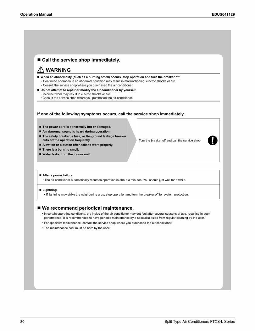
Operation Manual EDUS041129
Call the service shop immediately.
WARNINGWhen an abnormality (such as a burning smell) occurs, stop operation and turn the breaker off.
Continued operation in an abnormal condition may result in malfunctioning, electric shocks or fi re.•Consult the service shop where you purchased the air conditioner.•
Do not attempt to repair or modify the air conditioner by yourself.Incorrect work may result in electric shocks or fi re.•Consult the service shop where you purchased the air conditioner.•
If one of the following symptoms occurs, call the service shop immediately.
The power cord is abnormally hot or damaged.An abnormal sound is heard during operation.The safety breaker, a fuse, or the ground leakage breaker cuts off the operation frequently. A switch or a button often fails to work properly.There is a burning smell.Water leaks from the indoor unit.
Turn the breaker off and call the service shop.
After a power failureThe air conditioner automatically resumes operation in about 3 minutes. You should just wait for a while.•
LightningIf lightning may strike the neighboring area, stop operation and turn the breaker off for system protection.•
We recommend periodical maintenance.In certain operating conditions, the inside of the air conditioner may get foul after several seasons of use, resulting in poor •performance. It is recommended to have periodic maintenance by a specialist aside from regular cleaning by the user. For specialist maintenance, contact the service shop where you purchased the air conditioner.•The maintenance cost must be born by the user.•
80 Split Type Air Conditioners FTXS-L Series
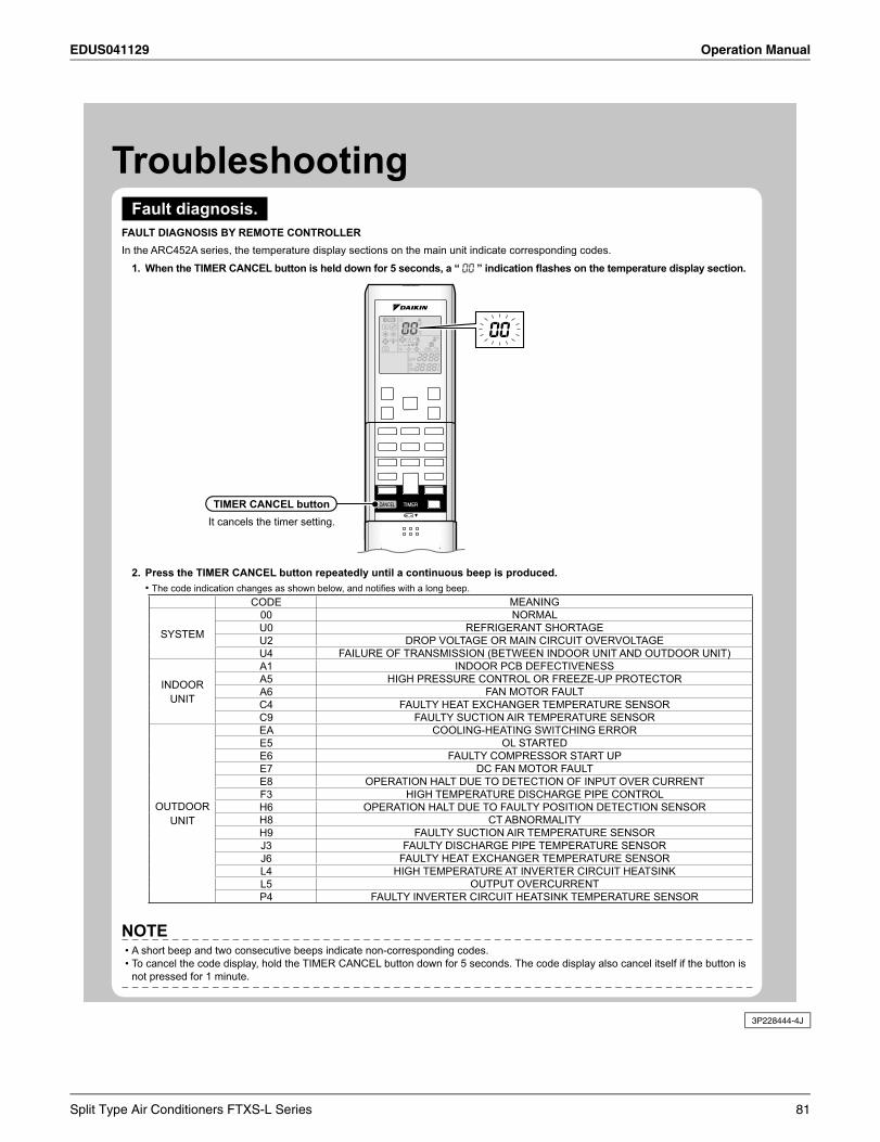
EDUS041129 Operation Manual
3P228444-4J
TroubleshootingFault diagnosis.
FAULT DIAGNOSIS BY REMOTE CONTROLLERIn the ARC452A series, the temperature display sections on the main unit indicate corresponding codes.
When the TIMER CANCEL button is held down for 5 seconds, a “ 1. ” indication fl ashes on the temperature display section.
Press the TIMER CANCEL button repeatedly until a continuous beep is produced.2.The code indication changes as shown below, and notifi es with a long beep.•
CODE MEANING
SYSTEM
00 NORMALU0 REFRIGERANT SHORTAGEU2 DROP VOLTAGE OR MAIN CIRCUIT OVERVOLTAGEU4 FAILURE OF TRANSMISSION (BETWEEN INDOOR UNIT AND OUTDOOR UNIT)
INDOORUNIT
A1 INDOOR PCB DEFECTIVENESSA5 HIGH PRESSURE CONTROL OR FREEZE-UP PROTECTORA6 FAN MOTOR FAULTC4 FAULTY HEAT EXCHANGER TEMPERATURE SENSORC9 FAULTY SUCTION AIR TEMPERATURE SENSOR
OUTDOORUNIT
EA COOLING-HEATING SWITCHING ERRORE5 OL STARTEDE6 FAULTY COMPRESSOR START UPE7 DC FAN MOTOR FAULTE8 OPERATION HALT DUE TO DETECTION OF INPUT OVER CURRENTF3 HIGH TEMPERATURE DISCHARGE PIPE CONTROLH6 OPERATION HALT DUE TO FAULTY POSITION DETECTION SENSORH8 CT ABNORMALITYH9 FAULTY SUCTION AIR TEMPERATURE SENSORJ3 FAULTY DISCHARGE PIPE TEMPERATURE SENSORJ6 FAULTY HEAT EXCHANGER TEMPERATURE SENSORL4 HIGH TEMPERATURE AT INVERTER CIRCUIT HEATSINKL5 OUTPUT OVERCURRENTP4 FAULTY INVERTER CIRCUIT HEATSINK TEMPERATURE SENSOR
NOTEA short beep and two consecutive beeps indicate non-corresponding codes.•To cancel the code display, hold the TIMER CANCEL button down for 5 seconds. The code display also cancel itself if the button is •not pressed for 1 minute.
TIMER CANCEL buttonIt cancels the timer setting.
Split Type Air Conditioners FTXS-L Series 81
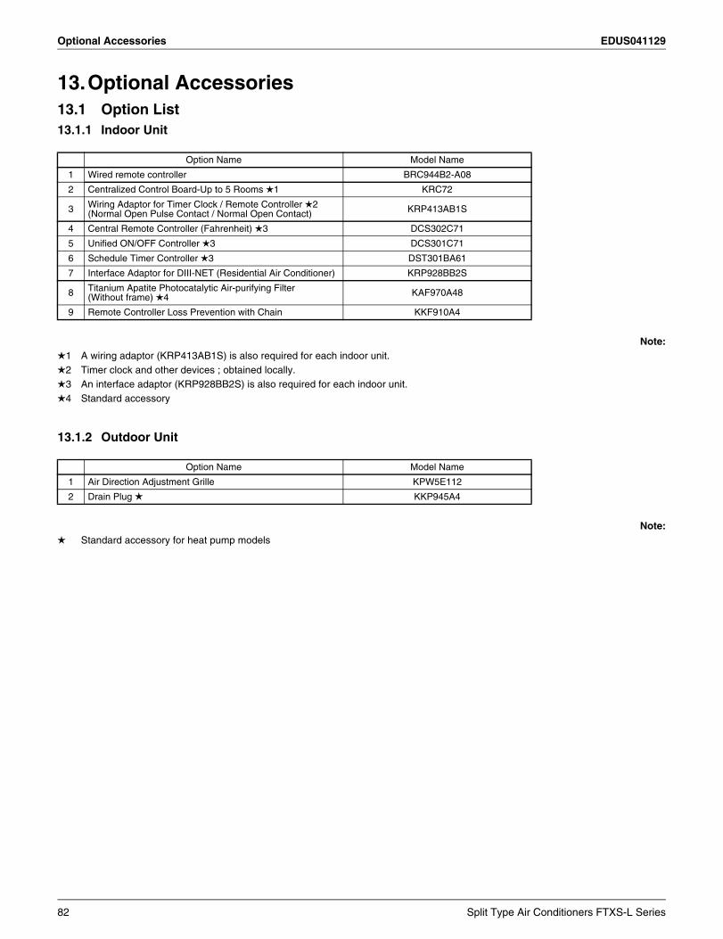
Optional Accessories EDUS041129
13.Optional Accessories13.1 Option List13.1.1 Indoor Unit
Note:1 A wiring adaptor (KRP413AB1S) is also required for each indoor unit.2 Timer clock and other devices ; obtained locally.3 An interface adaptor (KRP928BB2S) is also required for each indoor unit.4 Standard accessory
13.1.2 Outdoor Unit
Note: Standard accessory for heat pump models
Option Name Model Name
1 Wired remote controller BRC944B2-A08
2 Centralized Control Board-Up to 5 Rooms 1 KRC72
3 Wiring Adaptor for Timer Clock / Remote Controller 2(Normal Open Pulse Contact / Normal Open Contact) KRP413AB1S
4 Central Remote Controller (Fahrenheit) 3 DCS302C71
5 Unified ON/OFF Controller 3 DCS301C71
6 Schedule Timer Controller 3 DST301BA61
7 Interface Adaptor for DIII-NET (Residential Air Conditioner) KRP928BB2S
8 Titanium Apatite Photocatalytic Air-purifying Filter(Without frame) 4 KAF970A48
9 Remote Controller Loss Prevention with Chain KKF910A4
Option Name Model Name
1 Air Direction Adjustment Grille KPW5E112
2 Drain Plug KKP945A4
82 Split Type Air Conditioners FTXS-L Series
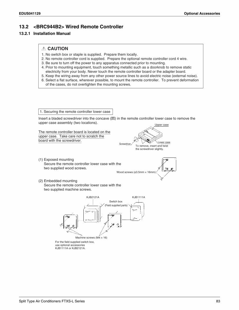
EDUS041129 Optional Accessories
13.2 <BRC944B2> Wired Remote Controller13.2.1 Installation Manual
Switch box (Field supplied parts)
Machine screws (M4 × 16)
For the field supplied switch box,use optional accessoriesKJB1111A or KJB2121A.
KJB2121A
CAUTION1. No switch box or staple is supplied. Prepare them locally.2. No remote controller cord is supplied. Prepare the optional remote controller cord 4 wire.3. Be sure to turn off the power to any apparatus connected prior to mounting.4. Prior to mounting equipment, touch something metallic such as a doorknob to remove static
electricity from your body. Never touch the remote controller board or the adapter board.5. Keep the wiring away from any other power source lines to avoid electric noise (external noise).6. Select a flat surface, wherever possible, to mount the remote controller. To prevent deformation
of the cases, do not overtighten the mounting screws.
Insert a bladed screwdriver into the concave ( ) in the remote controller lower case to remove the upper case assembly (two locations).
(1) Exposed mountingSecure the remote controller lower case with the two supplied wood screws.
(2) Embedded mountingSecure the remote controller lower case with the two supplied machine screws.
The remote controller board is located on the upper case. Take care not to scratch the board with the screwdriver.
1. Securing the remote controller lower case
Upper case
Lower caseScrewdriver
To remove, insert and twistthe screwdriver slightly.
Wood screws (φ3.5mm × 16mm)
KJB1111A
Split Type Air Conditioners FTXS-L Series 83
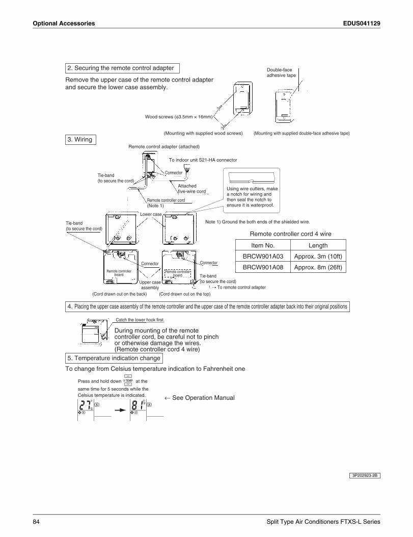
Optional Accessories EDUS041129
3P202923-2B
Remove the upper case of the remote control adapterand secure the lower case assembly.
During mounting of the remote controller cord, be careful not to pinch or otherwise damage the wires.(Remote controller cord 4 wire)
2. Securing the remote control adapter
3. Wiring
4. Placing the upper case assembly of the remote controller and the upper case of the remote controller adapter back into their original positions
5. Temperature indication change
Wood screws (φ3.5mm × 16mm)
(Mounting with supplied wood screws)
Remote control adapter (attached)
(Mounting with supplied double-face adhesive tape)
Double-faceadhesive tape
Attached five-wire cord
Remote controller cord (Note 1)
Connector
ConnectorConnector
Tie-band(to secure the cord)
Tie-band (to secure the cord)
Tie-band(to secure the cord)
Upper caseassembly
Lower case
(Cord drawn out on the back)
Catch the lower hook first.
(Cord drawn out on the top)To remote control adapter
Remote controllerboard
Remote controllerboard
Note 1) Ground the both ends of the shielded wire.
Using wire cutters, make a notch for wiring and then seal the notch to ensure it is waterproof.
To indoor unit S21-HA connector
Remote controller cord 4 wire
Item No.
BRCW901A03
BRCW901A08
Length
Approx. 3m (10ft)
Approx. 8m (26ft)
To change from Celsius temperature indication to Fahrenheit one
Press and hold down at the
same time for 5 seconds while the Celsius temperature is indicated. ← See Operation Manual
84 Split Type Air Conditioners FTXS-L Series
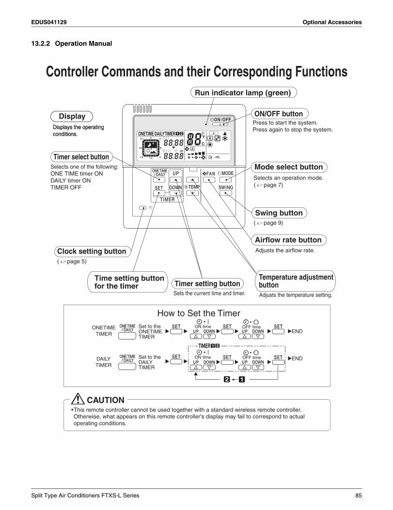
EDUS041129 Optional Accessories
13.2.2 Operation Manual
Controller Commands and their Corresponding FunctionsRun indicator lamp (green)
ON/OFF buttonPress to start the system.Press again to stop the system.
Mode select button
Swing button
Timer setting buttonSets the current time and timer.
Temperature adjustmentbuttonAdjusts the temperature setting.
Airflow rate buttonAdjusts the airflow rate.
Time setting buttonfor the timer
Display
Timer select button
Displays the operatingconditions.
Clock setting button
( page 9)
( page 7)
( page 5)
Selects an operation mode.
Displays the operatingconditions.
Selects one of the following:ONE TIME timer ON DAILY timer ONTIMER OFF
CAUTION•This remote controller cannot be used together with a standard wireless remote controller.Otherwise, what appears on this remote controller's display may fail to correspond to actual operating conditions.
Split Type Air Conditioners FTXS-L Series 85
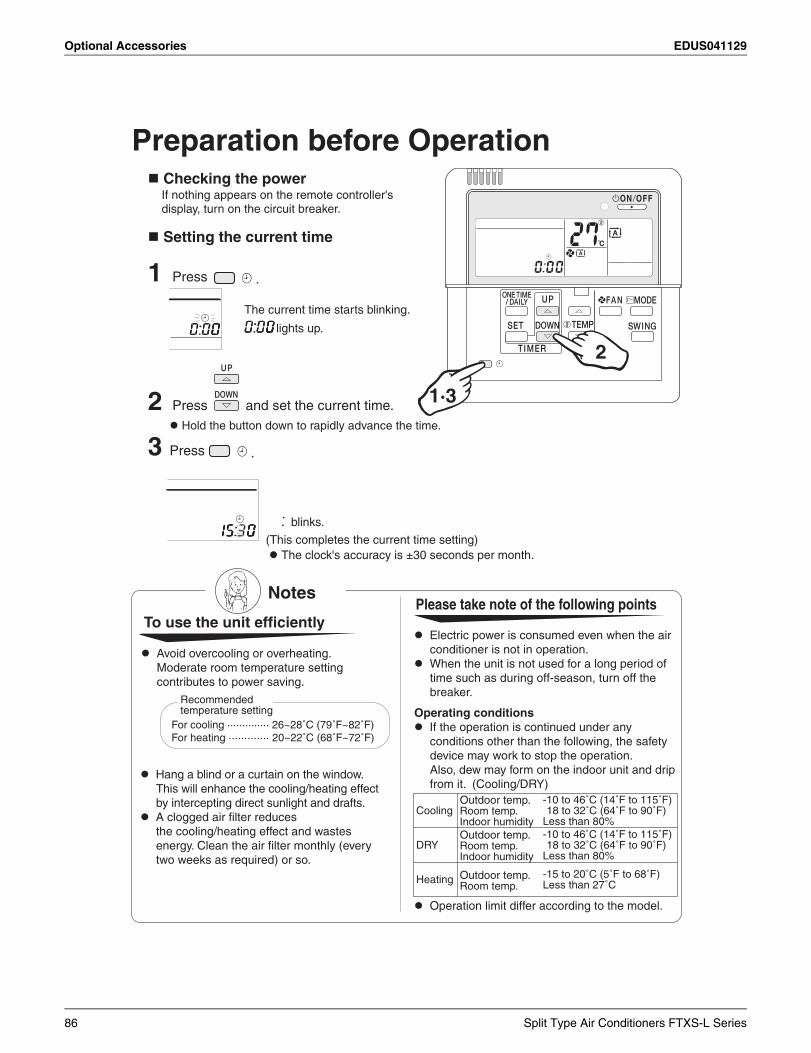
Optional Accessories EDUS041129
Preparation before Operation Checking the power
If nothing appears on the remote controller's display, turn on the circuit breaker.
Setting the current time
1 Press .
The current time starts blinking.
lights up.
2 Press and set the current time. Hold the button down to rapidly advance the time.
3 Press .
(This completes the current time setting) The clock's accuracy is ±30 seconds per month.
blinks.
2
1·3
Avoid overcooling or overheating. Moderate room temperature settingcontributes to power saving.
Hang a blind or a curtain on the window. This will enhance the cooling/heating effectby intercepting direct sunlight and drafts.
A clogged air filter reduces the cooling/heating effect and wastesenergy. Clean the air filter monthly (everytwo weeks as required) or so.
Please take note of the following points
Electric power is consumed even when the airconditioner is not in operation.
When the unit is not used for a long period oftime such as during off-season, turn off the breaker.
Operating conditions If the operation is continued under any
conditions other than the following, the safetydevice may work to stop the operation. Also, dew may form on the indoor unit and dripfrom it. (Cooling/DRY)
Operation limit differ according to the model.
Notes
To use the unit efficiently
Recommendedtemperature setting
For cooling ·············· 26~28˚C (79˚F~82˚F)For heating ············· 20~22˚C (68˚F~72˚F)
Cooling
DRY
Heating
Outdoor temp.Room temp.Indoor humidityOutdoor temp.Room temp.Indoor humidity
Outdoor temp.Room temp.
-10 to 46˚C (14˚F to 115˚F)18 to 32˚C (64˚F to 90˚F)
Less than 80%-10 to 46˚C (14˚F to 115˚F)18 to 32˚C (64˚F to 90˚F)
Less than 80%
-15 to 20˚C (5˚F to 68˚F)Less than 27˚C
86 Split Type Air Conditioners FTXS-L Series
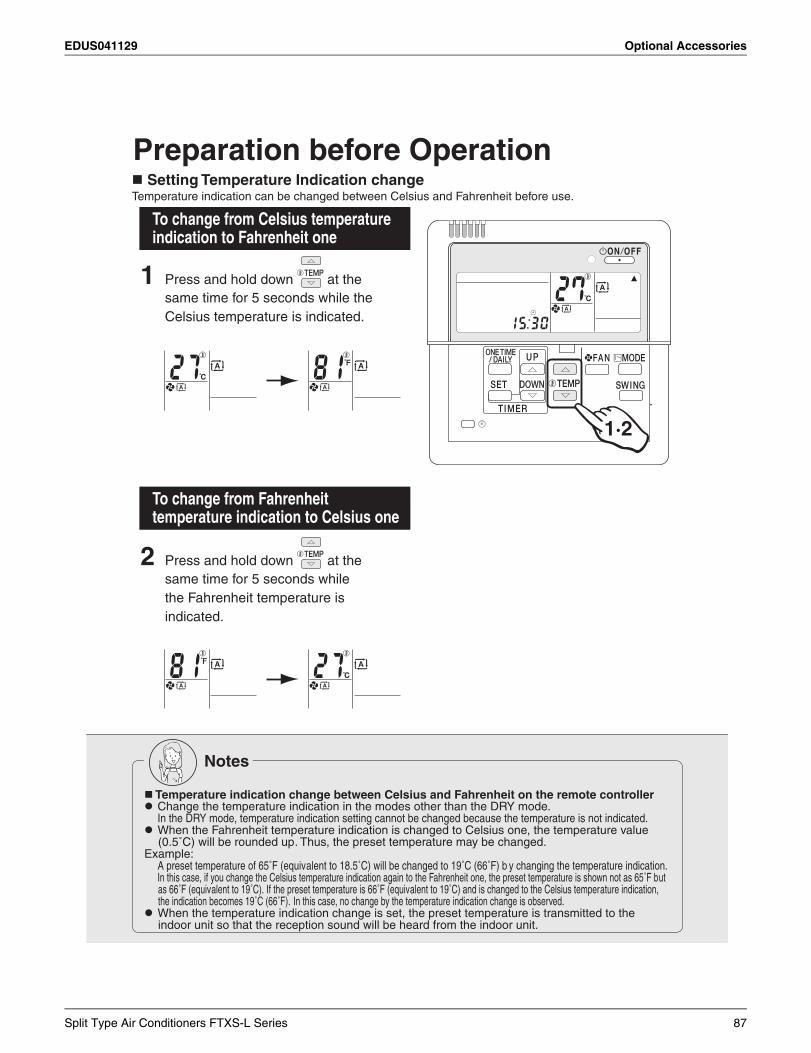
EDUS041129 Optional Accessories
1 Press and hold down at the same time for 5 seconds while the Celsius temperature is indicated.
Preparation before Operation
2 Press and hold down at the same time for 5 seconds while the Fahrenheit temperature is indicated.
Setting Temperature Indication changeTemperature indication can be changed between Celsius and Fahrenheit before use.
1·2
Notes
Temperature indication change between Celsius and Fahrenheit on the remote controller Change the temperature indication in the modes other than the DRY mode.
In the DRY mode, temperature indication setting cannot be changed because the temperature is not indicated. When the Fahrenheit temperature indication is changed to Celsius one, the temperature value
(0.5˚C) will be rounded up. Thus, the preset temperature may be changed.Example:
A preset temperature of 65˚F (equivalent to 18.5˚C) will be changed to 19˚C (66˚F) b y changing the temperature indication.In this case, if you change the Celsius temperature indication again to the Fahrenheit one, the preset temperature is shown not as 65˚F but as 66˚F (equivalent to 19˚C). If the preset temperature is 66˚F (equivalent to 19˚C) and is changed to the Celsius temperature indication, the indication becomes 19˚C (66˚F). In this case, no change by the temperature indication change is observed.
When the temperature indication change is set, the preset temperature is transmitted to the indoor unit so that the reception sound will be heard from the indoor unit.
To change from Celsius temperature indication to Fahrenheit one
To change from Fahrenheit temperature indication to Celsius one
Split Type Air Conditioners FTXS-L Series 87
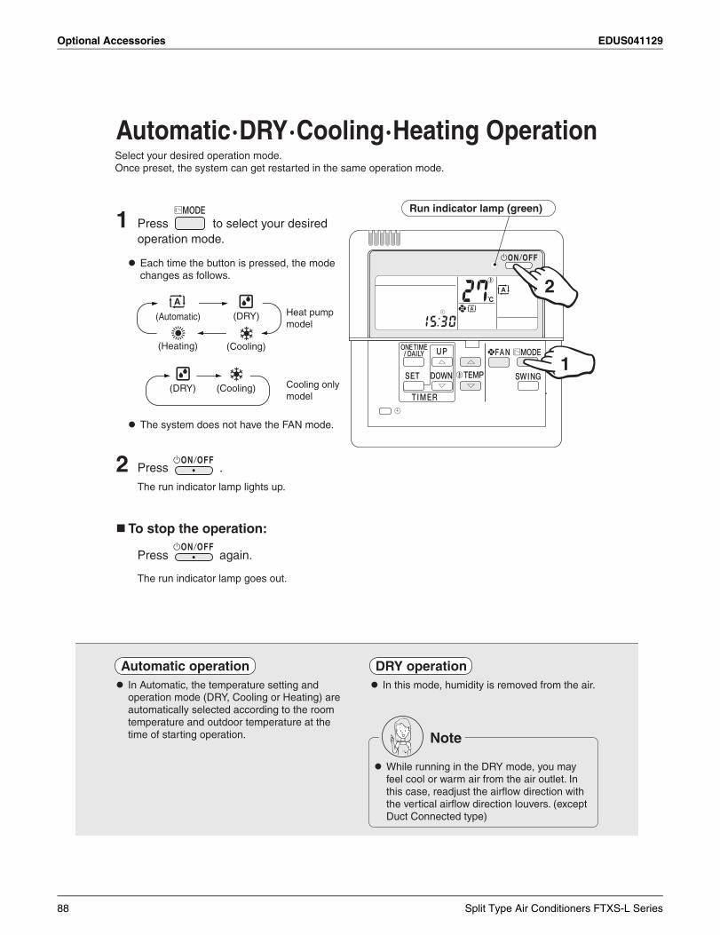
Optional Accessories EDUS041129
1 Press to select your desired
operation mode.
Each time the button is pressed, the mode changes as follows.
The system does not have the FAN mode.
Automatic · DRY · Cooling · Heating Operation
2 Press .
The run indicator lamp lights up.
Select your desired operation mode.Once preset, the system can get restarted in the same operation mode.
1
2
Run indicator lamp (green)
(Automatic) (DRY)
(Heating) (Cooling)
(DRY) (Cooling) Cooling onlymodel
Heat pumpmodel
To stop the operation:
Press again.
The run indicator lamp goes out.
In Automatic, the temperature setting and operation mode (DRY, Cooling or Heating) are automatically selected according to the room temperature and outdoor temperature at the time of starting operation.
DRY operation In this mode, humidity is removed from the air.
Note
While running in the DRY mode, you may feel cool or warm air from the air outlet. In this case, readjust the airflow direction with the vertical airflow direction louvers. (except Duct Connected type)
Automatic operation
88 Split Type Air Conditioners FTXS-L Series
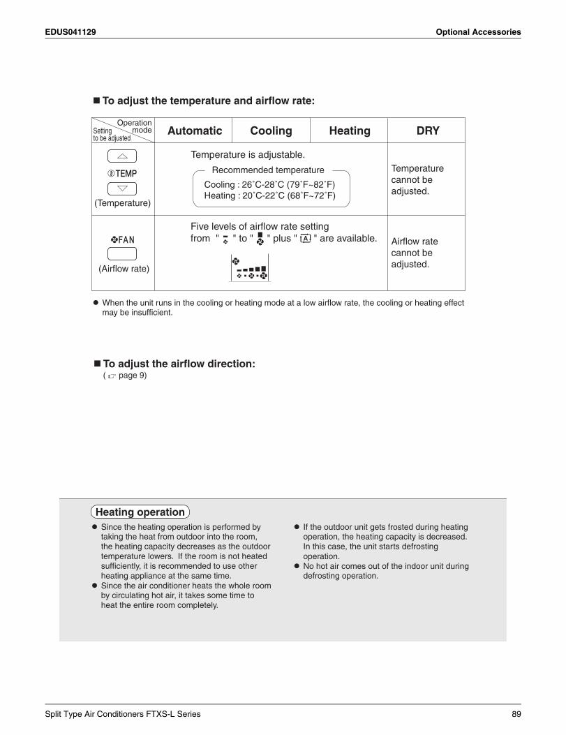
EDUS041129 Optional Accessories
Heating operation Since the heating operation is performed by
taking the heat from outdoor into the room, the heating capacity decreases as the outdoor temperature lowers. If the room is not heated sufficiently, it is recommended to use other heating appliance at the same time.
Since the air conditioner heats the whole room by circulating hot air, it takes some time to heat the entire room completely.
If the outdoor unit gets frosted during heating operation, the heating capacity is decreased. In this case, the unit starts defrosting operation.
No hot air comes out of the indoor unit during defrosting operation.
To adjust the temperature and airflow rate:
To adjust the airflow direction: ( page 9)
OperationmodeSetting
to be adjustedAutomatic DRYCooling Heating
(Temperature)
(Airflow rate)
Temperature cannot be adjusted.
Airflow rate cannot be adjusted.
Temperature is adjustable.
Recommended temperature
Cooling : 26˚C-28˚C (79˚F~82˚F)
Five levels of airflow rate settingfrom " " to " " plus " " are available.
Heating : 20˚C-22˚C (68˚F~72˚F)
When the unit runs in the cooling or heating mode at a low airflow rate, the cooling or heating effect may be insufficient.
Split Type Air Conditioners FTXS-L Series 89
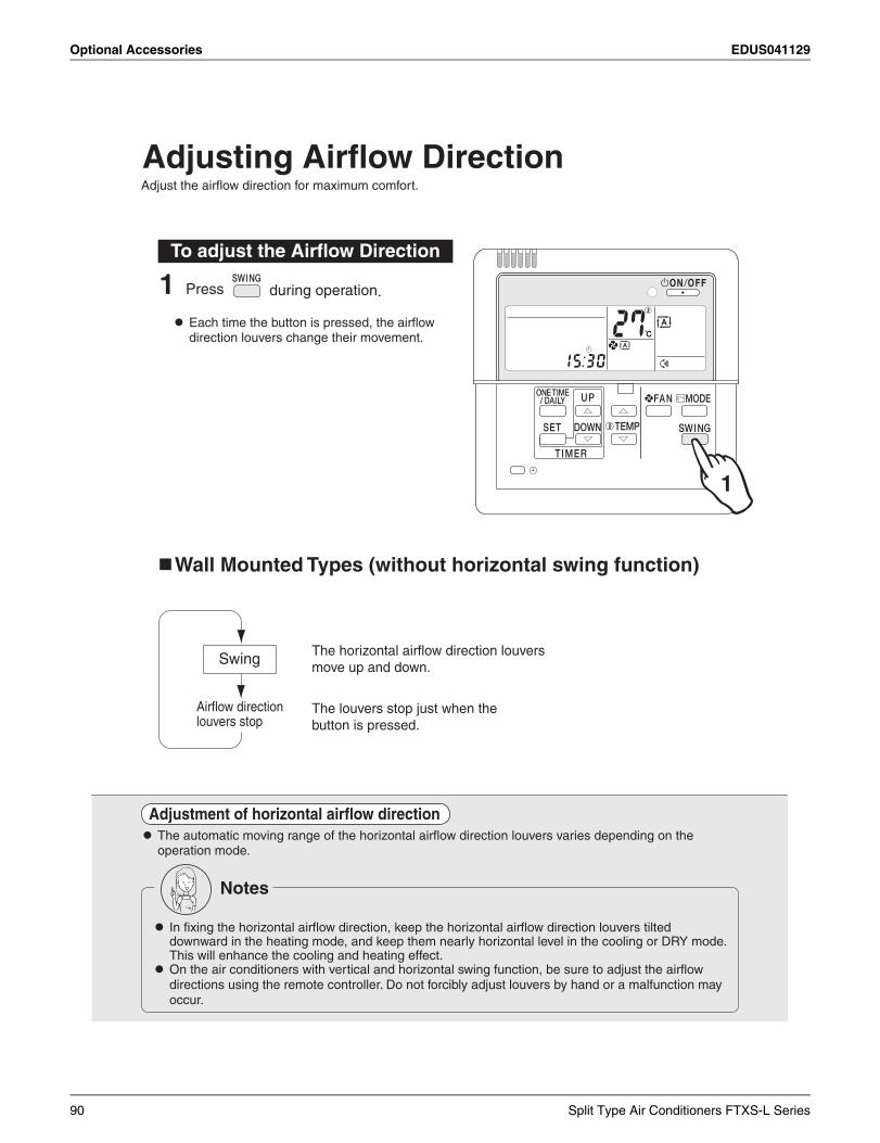
Optional Accessories EDUS041129
Notes
In fixing the horizontal airflow direction, keep the horizontal airflow direction louvers tilted downward in the heating mode, and keep them nearly horizontal level in the cooling or DRY mode. This will enhance the cooling and heating effect.
On the air conditioners with vertical and horizontal swing function, be sure to adjust the airflow directions using the remote controller. Do not forcibly adjust louvers by hand or a malfunction may occur.
Adjusting Airflow Direction
1 Press during operation.
Each time the button is pressed, the airflow direction louvers change their movement.
Adjust the airflow direction for maximum comfort.
To adjust the Airflow Direction
1
Wall Mounted Types (without horizontal swing function)
The horizontal airflow direction louversmove up and down.
The louvers stop just when the button is pressed.
Swing
Airflow directionlouvers stop
Adjustment of horizontal airflow direction The automatic moving range of the horizontal airflow direction louvers varies depending on the
operation mode.
90 Split Type Air Conditioners FTXS-L Series
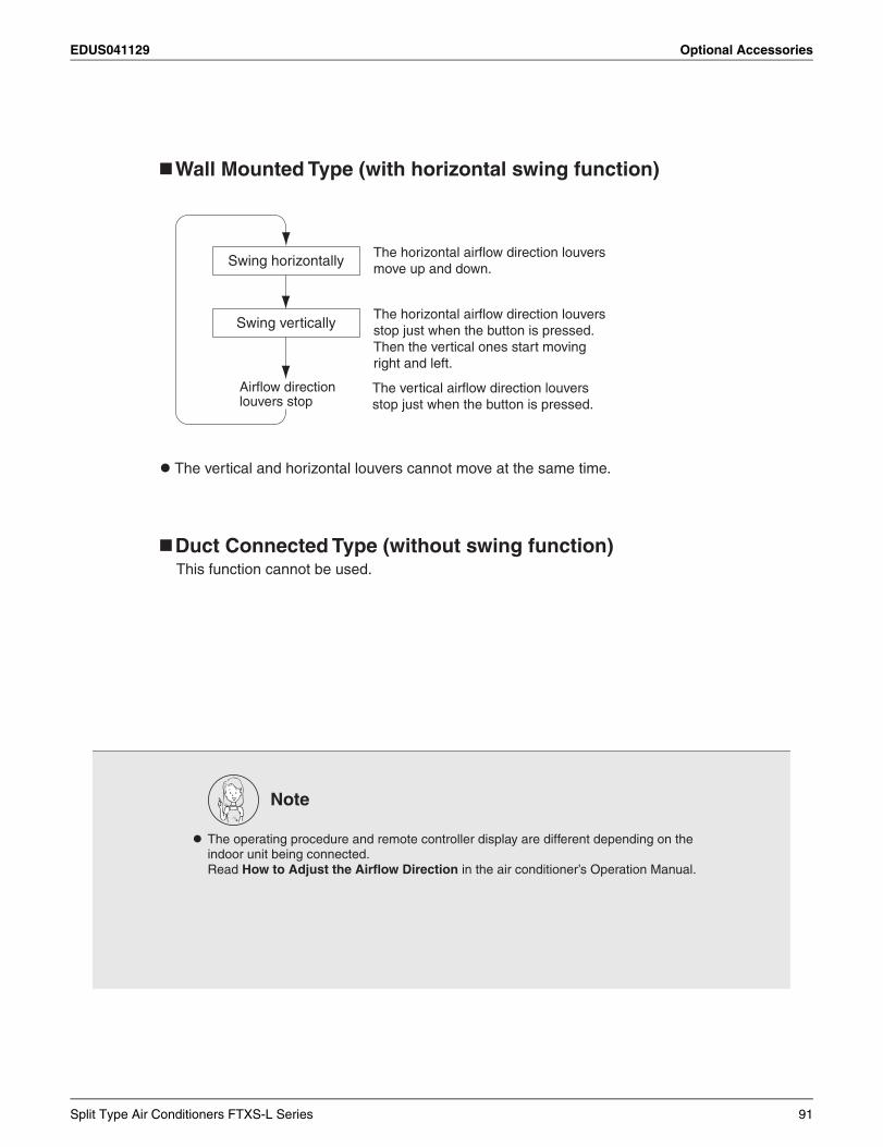
EDUS041129 Optional Accessories
Wall Mounted Type (with horizontal swing function)
The horizontal airflow direction louversmove up and down.
The horizontal airflow direction louversstop just when the button is pressed.Then the vertical ones start moving right and left.
The vertical airflow direction louvers stop just when the button is pressed.
Swing horizontally
Swing vertically
Airflow directionlouvers stop
The vertical and horizontal louvers cannot move at the same time.
Note
The operating procedure and remote controller display are different depending on the indoor unit being connected.
Read How to Adjust the Airflow Direction in the air conditioner’s Operation Manual.
Duct Connected Type (without swing function)This function cannot be used.
Split Type Air Conditioners FTXS-L Series 91
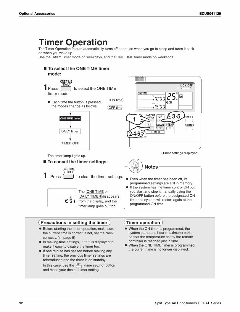
Optional Accessories EDUS041129
Timer Operation
To select the ONE TIME timer mode:
1 Press to select the ONE TIMEtimer mode.
Each time the button is pressed,the modes change as follows.
The Timer Operation feature automatically turns off operation when you go to sleep and turns it back on when you wake up.Use the DAILY Timer mode on weekdays, and the ONE TIME timer mode on weekends.
To cancel the timer settings:
1 Press to clear the timer settings.
Precautions in setting the timer Before starting the timer operation, make sure
the current time is correct. If not, set the clock correctly. ( page 5)
In making time settings, is displayed to make it easy to disable the timer too.
If one minute has passed before making any timer setting, the previous timer settings are reintroduced and the timer is on standby.
In this case, use the (time setting) button and make your desired timer settings.
ONE TIME timer
DAILY timer
TIMER OFF
ON time
OFF time
(Timer settings displayed)
1
2·4·6
3·5
The timer lamp lights up.
The ONE TIME or DAILY TIMER disappears from the display, and the timer lamp goes out too.
Notes
Even when the timer has been off, its programmed settings are still in memory.
If the system has the timer control ON but you start and stop it manually using the ON/OFF button before the designated ON time, the system will restart again at the programmed ON time.
Timer operation When the ON timer is programmed, the
system starts one hour (maximum) earlier so that the temperature set by the remote controller is reached just in time.
When the ONE TIME timer is programmed, the current time is no longer displayed.
92 Split Type Air Conditioners FTXS-L Series
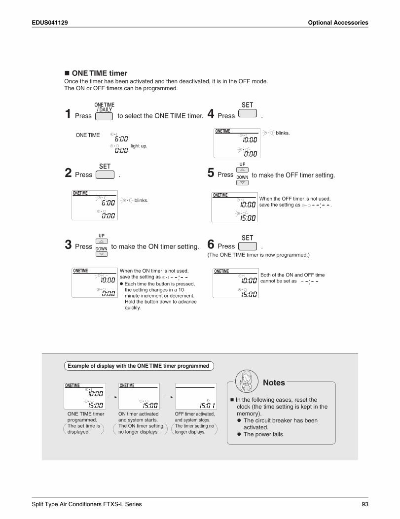
EDUS041129 Optional Accessories
1 Press to select the ONE TIME timer.
2 Press .
3 Press to make the ON timer setting.
Example of display with the ONE TIME timer programmed
ONE TIME timerOnce the timer has been activated and then deactivated, it is in the OFF mode.The ON or OFF timers can be programmed.
light up.
ONE TIME
blinks.
Each time the button is pressed, the setting changes in a 10-minute increment or decrement. Hold the button down to advancequickly.
When the ON timer is not used, save the setting as
4 Press .
5 Press to make the OFF timer setting.
6 Press .(The ONE TIME timer is now programmed.)
Both of the ON and OFF timecannot be set as
blinks.
When the OFF timer is not used, save the setting as .
ONE TIME timer programmed.The set time is displayed.
ON timer activated and system starts.The ON timer setting no longer displays.
OFF timer activated, and system stops. The timer setting no longer displays.
Notes
In the following cases, reset the clock (the time setting is kept in the
memory). The circuit breaker has been
activated. The power fails.
Split Type Air Conditioners FTXS-L Series 93
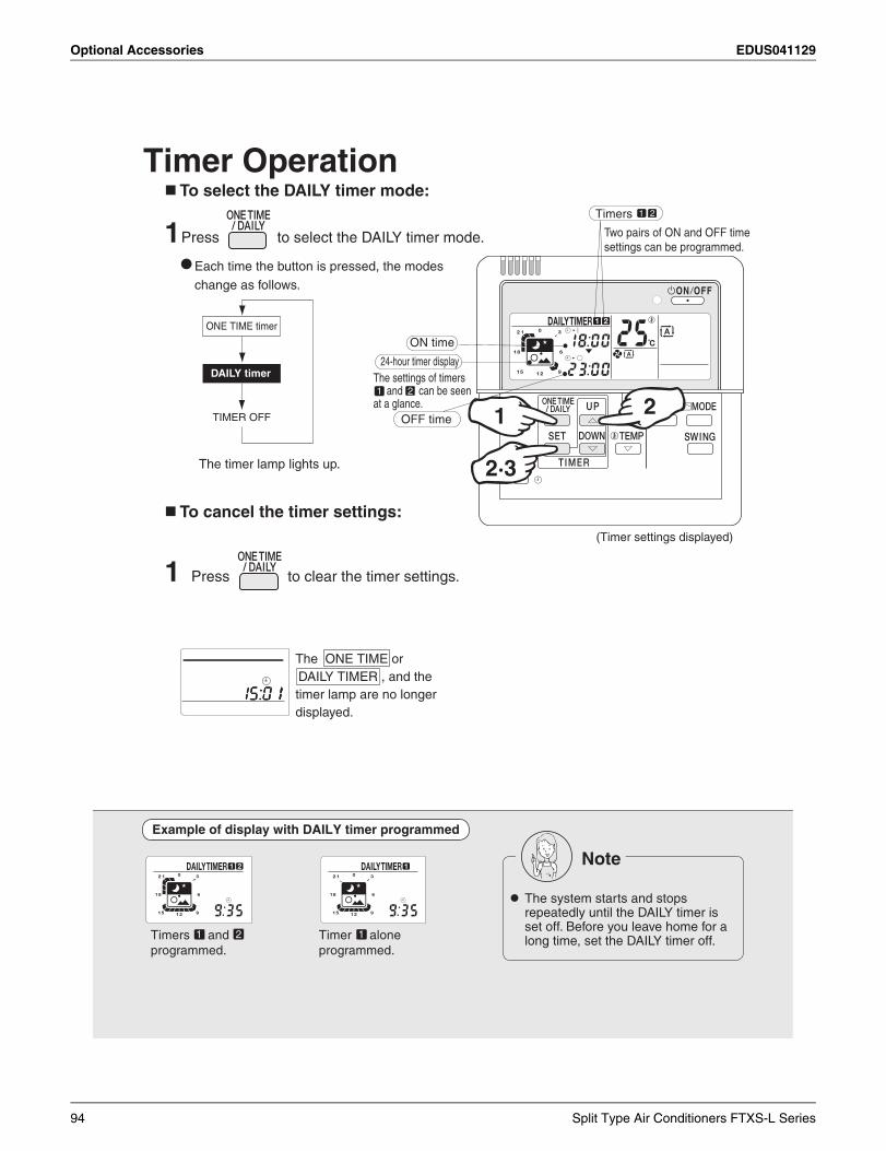
Optional Accessories EDUS041129
Timer Operation To select the DAILY timer mode:
1 Press to select the DAILY timer mode.
Each time the button is pressed, the modes change as follows.
To cancel the timer settings:
1 Press to clear the timer settings.
Example of display with DAILY timer programmed
ONE TIME timer
DAILY timer
TIMER OFF
The timer lamp lights up.
1 2
1 2
ON time
24-hour timer display
OFF time
Timers
The settings of timers and can be seen at a glance.
Two pairs of ON and OFF time settings can be programmed.
(Timer settings displayed)
1
2·3
2
The ONE TIME or DAILY TIMER , and the timer lamp are no longer displayed.
Timers and programmed.
Timer alone programmed.
1 12
Note
The system starts and stops repeatedly until the DAILY timer is set off. Before you leave home for a long time, set the DAILY timer off.
94 Split Type Air Conditioners FTXS-L Series
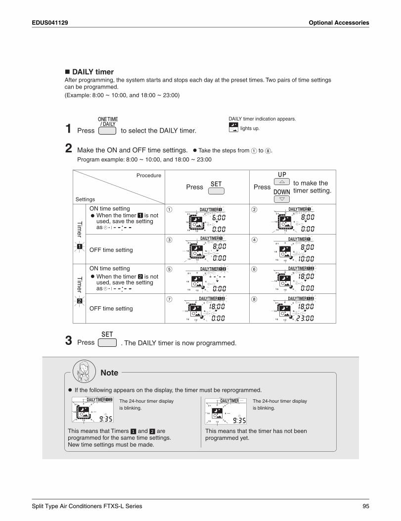
EDUS041129 Optional Accessories
1 Press to select the DAILY timer.
2 Make the ON and OFF time settings. Take the steps from � to �.
Program example: 8:00 ~ 10:00, and 18:00 ~ 23:00
DAILY timerAfter programming, the system starts and stops each day at the preset times. Two pairs of time settings can be programmed.(Example: 8:00 ~ 10:00, and 18:00 ~ 23:00)
DAILY timer indication appears.
lights up.
3 Press . The DAILY timer is now programmed.
Note
If the following appears on the display, the timer must be reprogrammed.
The 24-hour timer display is blinking.
The 24-hour timer display is blinking.
This means that Timers � and � are programmed for the same time settings. New time settings must be made.
This means that the timer has not been programmed yet.
When the timer is not used, save the setting as
Press Pressto make the timer setting.
1
Procedure
Settings
ON time setting
OFF time setting
OFF time setting
2
ON time setting
2
1
� �
� �
� �
�
Tim
erT
imer
When the timer is not used, save the setting as
Split Type Air Conditioners FTXS-L Series 95
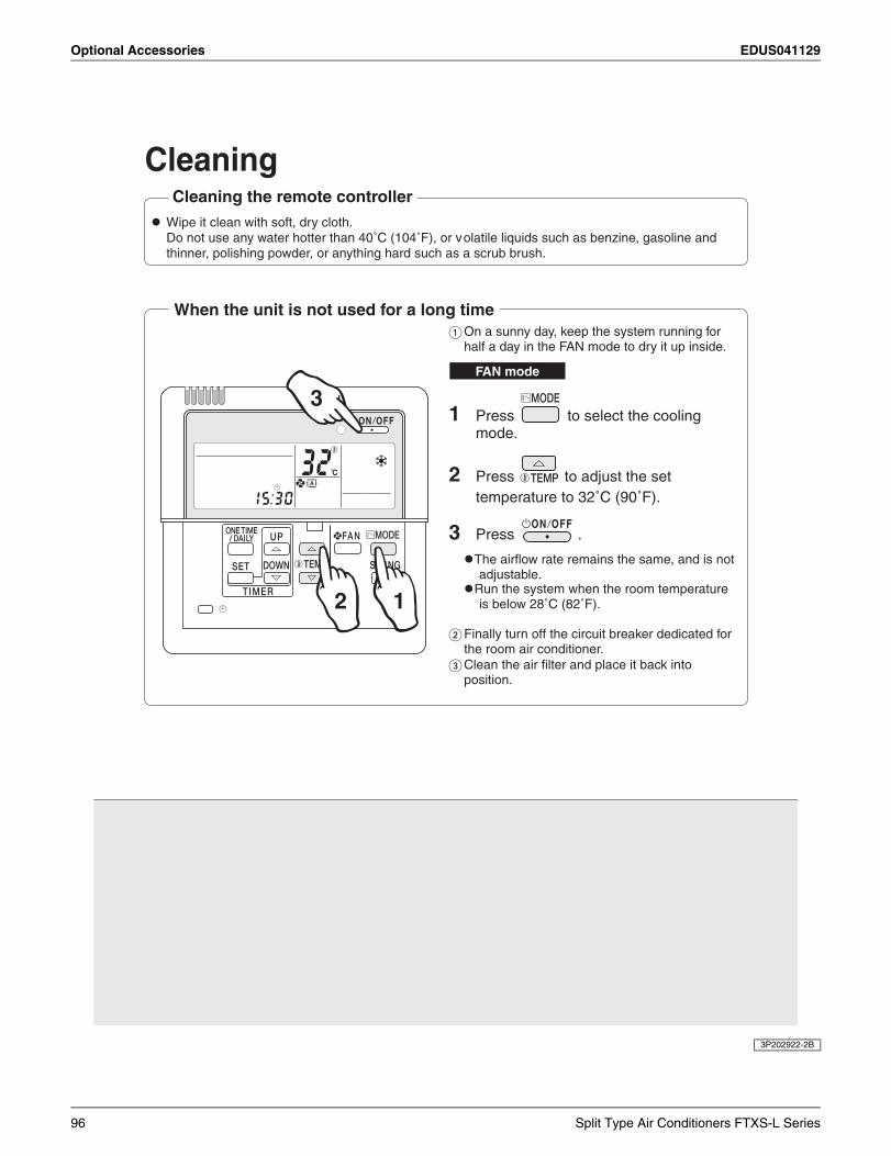
Optional Accessories EDUS041129
3P202922-2B
CleaningCleaning the remote controller
Wipe it clean with soft, dry cloth.Do not use any water hotter than 40˚C (104˚F), or volatile liquids such as benzine, gasoline and thinner, polishing powder, or anything hard such as a scrub brush.
When the unit is not used for a long time� On a sunny day, keep the system running for
half a day in the FAN mode to dry it up inside.
3
12
FAN mode
1 Press to select the cooling mode.
2 Press to adjust the set
temperature to 32˚C (90˚F).
3 Press .
The airflow rate remains the same, and is not adjustable.
Run the system when the room temperature is below 28˚C (82˚F).
� Finally turn off the circuit breaker dedicated for the room air conditioner.
� Clean the air filter and place it back into position.
96 Split Type Air Conditioners FTXS-L Series
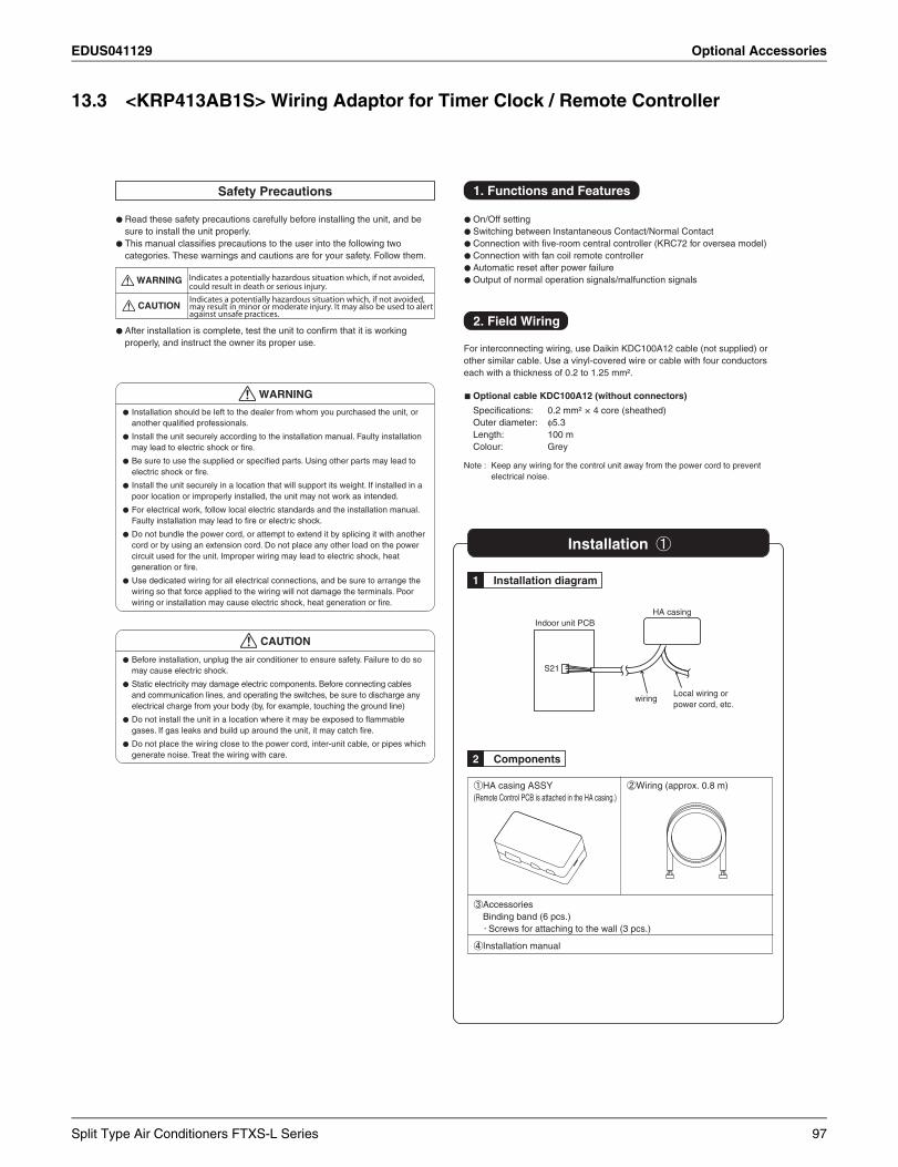
EDUS041129 Optional Accessories
13.3 <KRP413AB1S> Wiring Adaptor for Timer Clock / Remote Controller
Indicates a potentially hazardous situation which, if not avoided, could result in death or serious injury.Indicates a potentially hazardous situation which, if not avoided, may result in minor or moderate injury. It may also be used to alertagainst unsafe practices.
Split Type Air Conditioners FTXS-L Series 97
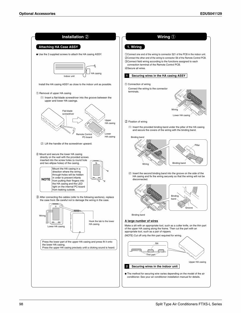
Optional Accessories EDUS041129
98 Split Type Air Conditioners FTXS-L Series
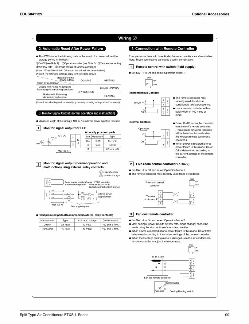
EDUS041129 Optional Accessories
Split Type Air Conditioners FTXS-L Series 99
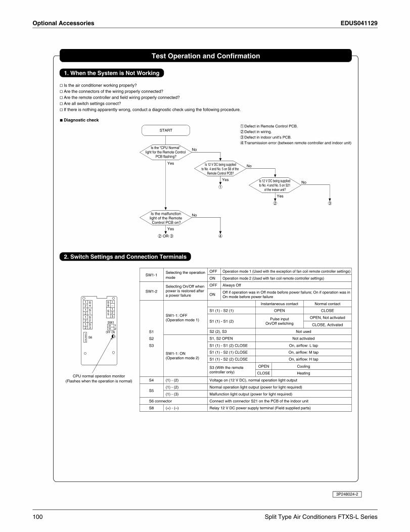
Optional Accessories EDUS041129
3P248024-2
100 Split Type Air Conditioners FTXS-L Series
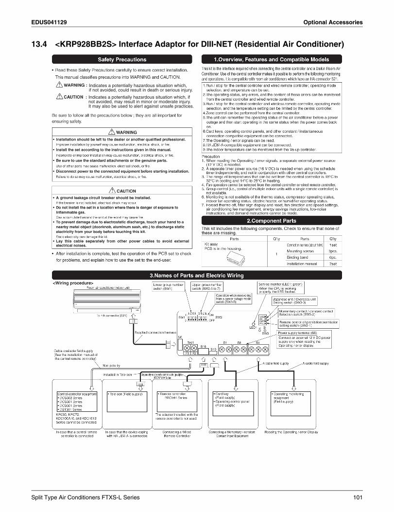
EDUS041129 Optional Accessories
13.4 <KRP928BB2S> Interface Adaptor for DIII-NET (Residential Air Conditioner)
Indicates a potentially hazardous situation which, if not avoided, may result in minor or moderate injury. It may also be used to alert against unsafe practices.
Indicates a potentially hazardous situation which,if not avoided, could result in death or serious injury.
Split Type Air Conditioners FTXS-L Series 101

Optional Accessories EDUS041129
3P248024-1A
102 Split Type Air Conditioners FTXS-L Series
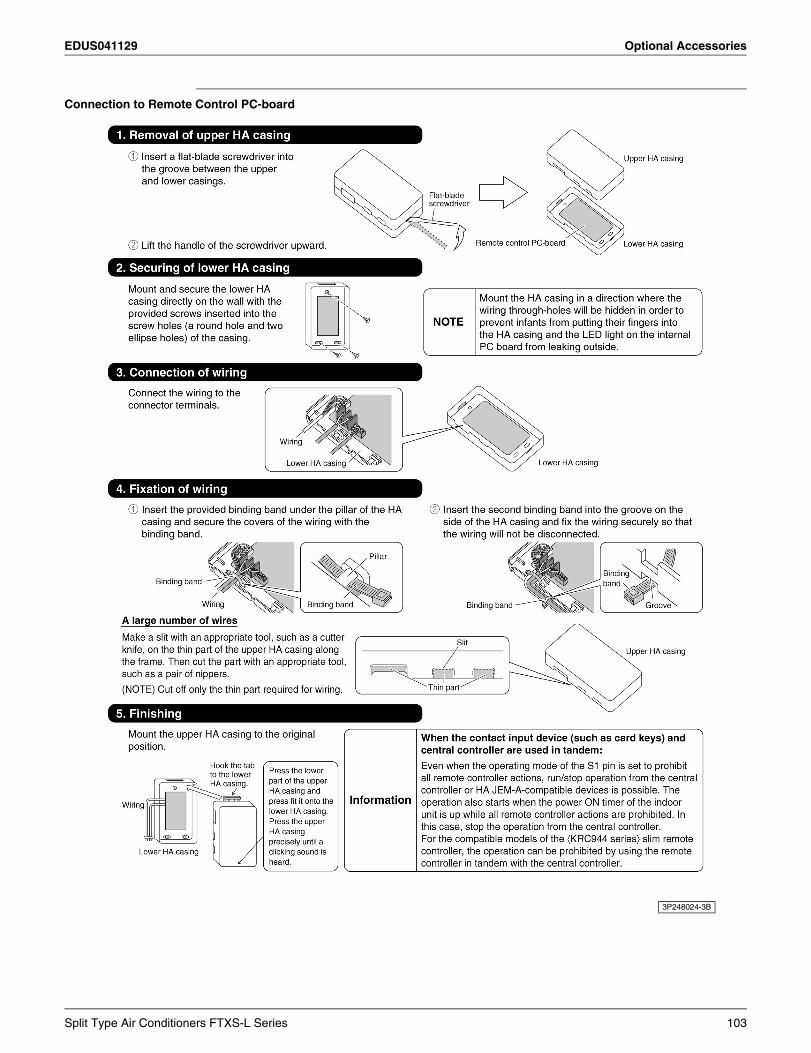
EDUS041129 Optional Accessories
Connection to Remote Control PC-board
3P248024-3B
Split Type Air Conditioners FTXS-L Series 103
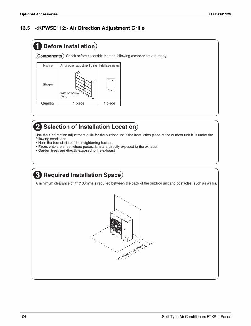
Optional Accessories EDUS041129
13.5 <KPW5E112> Air Direction Adjustment Grille
1 Before Installation
2 Selection of Installation Location
3 Required Installation Space
Components Check before assembly that the following components are ready.
Name
Shape
Quantity
Air direction adjustment grille
With setscrew(M5)
1 piece
Installation manual
1 piece
100mm or more
Near the boundaries of the neighboring houses.Faces onto the street where pedestrians are directly exposed to the exhaust.Garden trees are directly exposed to the exhaust.
Use the air direction adjustment grille for the outdoor unit if the installation place of the outdoor unit falls under the following conditions.
A minimum clearance of 4” (100mm) is required between the back of the outdoor unit and obstacles (such as walls).
�
�
�
4” (100mm or m
ore
104 Split Type Air Conditioners FTXS-L Series
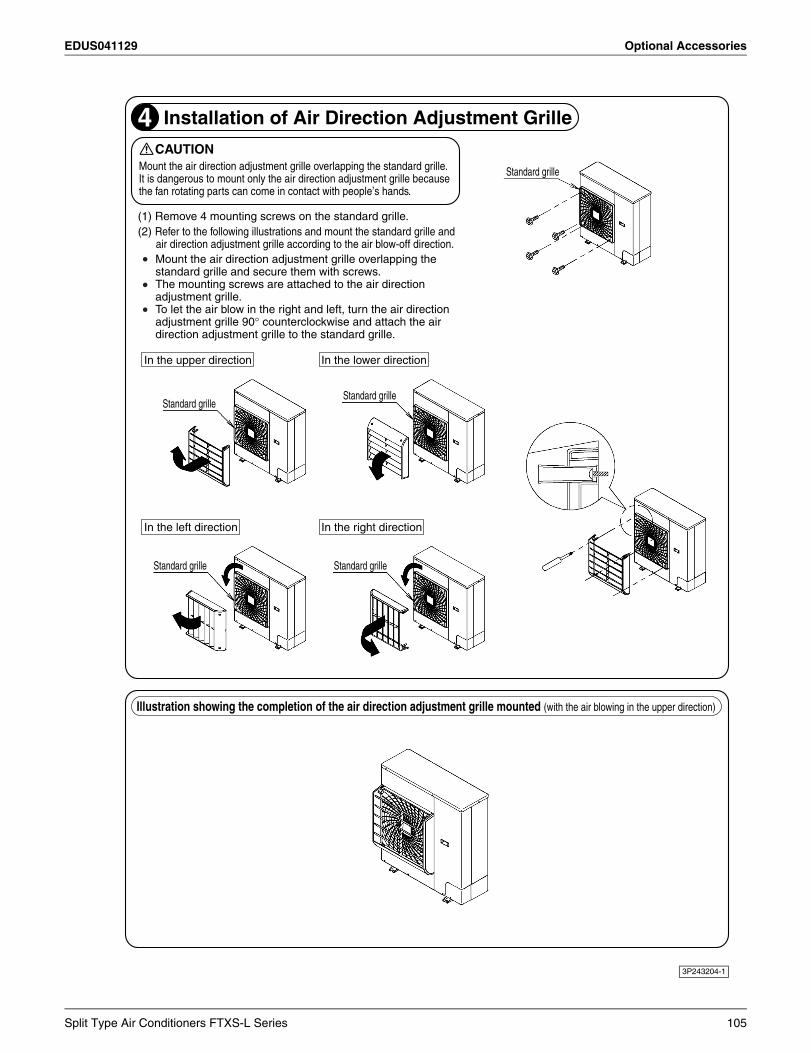
EDUS041129 Optional Accessories
3P243204-1
4 Installation of Air Direction Adjustment Grille
Mount the air direction adjustment grille overlapping the standard grille and secure them with screws.The mounting screws are attached to the air direction adjustment grille.To let the air blow in the right and left, turn the air direction adjustment grille 90° counterclockwise and attach the air direction adjustment grille to the standard grille.
CAUTION
Standard grille
Standard grille
Standard grille
Standard grille
Standard grille
In the upper direction In the lower direction
In the left direction In the right direction
Mount the air direction adjustment grille overlapping the standard grille. It is dangerous to mount only the air direction adjustment grille because the fan rotating parts can come in contact with people’s hands.
(1) Remove 4 mounting screws on the standard grille.(2) Refer to the following illustrations and mount the standard grille and
air direction adjustment grille according to the air blow-off direction.
Illustration showing the completion of the air direction adjustment grille mounted (with the air blowing in the upper direction)
Split Type Air Conditioners FTXS-L Series 105
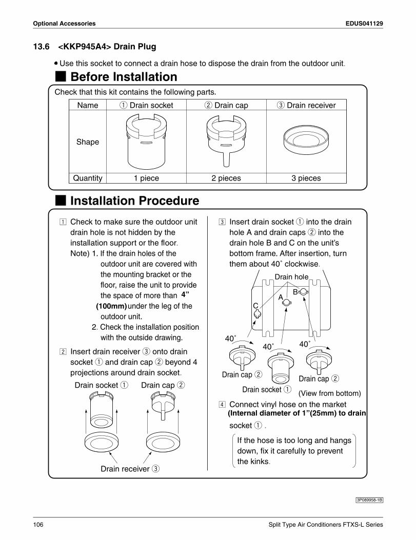
Optional Accessories EDUS041129
13.6 <KKP945A4> Drain Plug
3P089958-1B
(100mm)
4”
(Internal diameter of 1”(25mm) to drain
106 Split Type Air Conditioners FTXS-L Series
Specifications, designs and other content appearing in this brochure are current as of May 2012 but subject to change without notice.
Daikin products are manufactured for export to numerous countries throughout the world. Prior to purchase, please confirm with your local authorized importer, distributor and/or retailer whether this product conforms to the applicable standards, and is suitable for use, in the region where the product will be used. This statement does not purport to exclude, restrict or modify the application of any local legislation.
Ask a qualified installer or contractor to install this product. Do not try to install the product yourself. Improper installation can result in water or refrigerant leakage, electrical shock, fire or explosion.
Use only those parts and accessories supplied or specified by Daikin. Ask a qualified installer or contractor to install those parts and accessories. Use of unauthorized parts and accessories or improper installation of parts and accessories can result in water or refrigerant leakage, electrical shock, fire or explosion.
Read the User's Manual carefully before using this product. The User's Manual provides important safety instructions and warnings. Be sure to follow these instructions and warnings.
If you have any inquiries, please contact your local importer, distributor and/or retailer.
Organization:DAIKIN INDUSTRIES, LTD.AIR CONDITIONING MANUFACTURING DIVISION
Scope of Registration:THE DESIGN/DEVELOPMENT AND MANUFACTURE OF COMMERCIAL AIR CONDITIONING, HEATING, COOLING, REFRIGERATING EQUIPMENT, HEATING EQUIPMENT, RESIDENTIAL AIR CONDITIONING EQUIPMENT, HEAT RECLAIM VENTILATION, AIR CLEANING EQUIPMENT, COMPRESSORS AND VALVES.
Organization:DAIKIN INDUSTRIES(THAILAND) LTD.
Scope of Registration:THE DESIGN/DEVELOPMENTAND MANUFACTURE OF AIR CONDITIONERS AND THE COMPONENTS INCLUDING COMPRESSORS USED FOR THEM
All of the Daikin Group’s business facilities and subsidiaries in Japan are certified under the ISO 14001 international standard for environment management.
Daikin, Daikin AC Absolute Comfort, and its design, VRV, REFNET, and Quaternity are trademarks of Daikin Industries, LTD. All rights reserved.
2011 Daikin Industries, LTD.
1645 Wallace Drive, Suite 110Carrollton, TX75006
1. Air conditioners should not be installed in areas where corrosive gases, such as acid gas or alkaline gas, are produced.2. If the outdoor unit is to be installed close to the sea shore, direct exposure to the sea breeze should be avoided. If you need to install the outdoor unit close to the sea shore, contact your local distributor.
Cautions on product corrosion
EDUS041129Printed in U.S.A. 05/12 AK.B
Warning
Dealer
c
Top Related