


Languages
Pages
Legal

ENGINE – 1KD-FTV AND 2KD-FTV ENGINES EG-147
ENGINE CONTROL SYSTEM
1. General
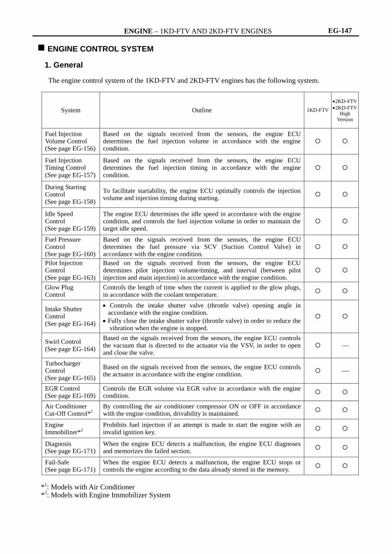
The engine control system of the 1KD-FTV and 2KD-FTV engines has the following system.
System Outline 1KD-FTV
2KD-FTV
2KD-FTV High
Version
Fuel Injection Volume Control (See page EG-156)
Based on the signals received from the sensors, the engine ECU determines the fuel injection volume in accordance with the engine condition.
Fuel Injection Timing Control (See page EG-157)
Based on the signals received from the sensors, the engine ECU determines the fuel injection timing in accordance with the engine condition.
During Starting Control (See page EG-158)
To facilitate startability, the engine ECU optimally controls the injection volume and injection timing during starting.
Idle Speed Control (See page EG-159)
The engine ECU determines the idle speed in accordance with the engine condition, and controls the fuel injection volume in order to maintain the target idle speed.
Fuel Pressure Control (See page EG-160)
Based on the signals received from the sensors, the engine ECU determines the fuel pressure via SCV (Suction Control Valve) in accordance with the engine condition.
Pilot Injection Control (See page EG-163)
Based on the signals received from the sensors, the engine ECU determines pilot injection volume/timing, and interval (between pilot injection and main injection) in accordance with the engine condition.
Glow Plug Control
Controls the length of time when the current is applied to the glow plugs, in accordance with the coolant temperature.
Intake Shutter Control (See page EG-164)
Controls the intake shutter valve (throttle valve) opening angle in accordance with the engine condition.
Fully close the intake shutter valve (throttle valve) in order to reduce the vibration when the engine is stopped.
Swirl Control (See page EG-164)
Based on the signals received from the sensors, the engine ECU controls the vacuum that is directed to the actuator via the VSV, in order to open and close the valve.
Turbocharger Control (See page EG-165)
Based on the signals received from the sensors, the engine ECU controls the actuator in accordance with the engine condition.
EGR Control (See page EG-169)
Controls the EGR volume via EGR valve in accordance with the engine condition.
Air Conditioner Cut-Off Control*
1
By controlling the air conditioner compressor ON or OFF in accordance with the engine condition, drivability is maintained.
Engine Immobilizer*
2
Prohibits fuel injection if an attempt is made to start the engine with an invalid ignition key.
Diagnosis (See page EG-171)
When the engine ECU detects a malfunction, the engine ECU diagnoses and memorizes the failed section.
Fail-Safe (See page EG-171)
When the engine ECU detects a malfunction, the engine ECU stops or controls the engine according to the data already stored in the memory.
*
1: Models with Air Conditioner
*2: Models with Engine Immobilizer System

ENGINE – 1KD-FTV AND 2KD-FTV ENGINES EG-148
2. Construction The configuration of the engine control system in the 1KD-FTV and 2KD-FTV engines is as shown in the following chart.
CRANKSHAFT POSITION SENSOR
CAMSHAFT POSITION SENSOR
FUEL PRESSURE SENSOR
TURBO PRESSURE SENSOR
INTAKE AIR TEMP. SENSOR
WATER TEMP. SENSOR
INTAKE SHUTTER VALVE
POSITION SENSOR
ACCELERATOR PEDAL POSITION SENSOR
AIR FLOW METER*1
FUEL TEMP. SENSOR
EGR VALVE POSITION SENSOR*
3
STOP LIGHT SWITCH
NE
G
PCR1
PIM
THA
THW
VLU
VPA
VG
THF
Engine
ECU
#1
#2
#3
#4
INJF
PCV
SCV
EGR
EGRC
GREL
IREL
E D
U
No.1 INJECTOR
No.2 INJECTOR
No.3 INJECTOR
No.4 INJECTOR
SUCTION CONTROL VALVE
INTAKE SHUTTER CONTROL
Torque Motor (Rotary Solenoid type)
EGR CONTROL
Vacuum Regulating Valve (for EGR Valve Control)
VSV (for EGR Valve Close)*1
GLOW PLUG CONTROL
Glow Plug Relay
EDU RELAY
Turbo Motor Driver
TURBOCHARGER CONTROL*1
Nozzle Vane Position Sensor
DC Motor
271EG132
(Continued)
INTAKE AIR TEMP. SENSOR*2
THIA
STP
ST1-
VPA2
ALTERNATOR
VSV (for Swirl Control Valve)*1
Close)
EGLS
ALT
LUSL
VNTO
VNTI

ENGINE – 1KD-FTV AND 2KD-FTV ENGINES EG-149
*
1: Only for 1KD-FTV Engine
*2: Only for Models with Intercooler
*3: Only for 2KD-FTV Engine
*4: Only for Models with Cruise Control System
*5: Only for Models with Engine Immobilizer System
*6: Only for Models with Automatic Transmission
*7: Only for Models with Air Conditioner System
*8: Only for Models with Multi Information Display
IGNITION SWITCH
Starting Signal (ST Terminal)
Ignition Signal (IG Terminal)
STA
IGSW
271EG133
CRUISE CONTROL MAIN SWITCH*4
CCS
BATTERY BATT
MAIN RELAY MREL
+B
TRANSPONDER KEY ECU*5
IMO
IMI
DLC3
TC
SIL
WFSE
TRANSMISSION CONTROL ECU*6
ECT CONTROL
CAN+
CAN-
Engine ECU
ACT
AC1
W
A/C AMPLIFIER*7
Magnetic Clutch Actuation Signal
Engine Idle-Up Signal
Check Engine Warning Light
GIND Glow Indicator Light
Cruise MAIN Indicator Light*
4
Vehicle Speed Signal
PI
SPD
DM Injection Volume Signal*
8
Tachometer
Water Temp. Signal
TACH
THWO
COMBINATION METER

ENGINE – 1KD-FTV AND 2KD-FTV ENGINES EG-150
3. Engine Control System Diagram
Accelerator Pedal Position Sensor
Ignition Switch Signal
Air conditioner Signal*1
Vehicle Speed Signal
Engine
ECU
Atmospheric Pressure Sensor
Glow Relay
Suction Control Valve
Fuel Temp. Sensor
Supply Pump
EDU
EDU Relay
Common-Rail
Fuel Pressure Sensor
Intake Air Temp. Sensor*2
Intake Shutter
Assy. E-VRV
Turbo Pressure
Sensor
Glow Plug
Water Temp. Sensor
Crankshaft Position Sensor
Camshaft Position Sensor
Injector
Stop Light Switch Signal
Intake Air Temp.
Sensor*3
VSV*2
(EGR Valve Close)
Air Flow Meter*2
Intake Air Temp. Sensor*4
VSV*2 (Swirl Control
Valve) Turbo Motor Driver*2
DC Motor*2
Nozzle Vane Position Sensor*2
EGR Valve
Position Sensor*4
*1: Only for Models with Air Conditioner
*2: Only for 1KD-FTV Engine
*3: Only for Models with Intercooler
*4: Only for 2KD-FTV Engine
271EG134
Intercooler*3
ENGINE – 1KD-FTV AND 2KD-FTV ENGINES EG-151
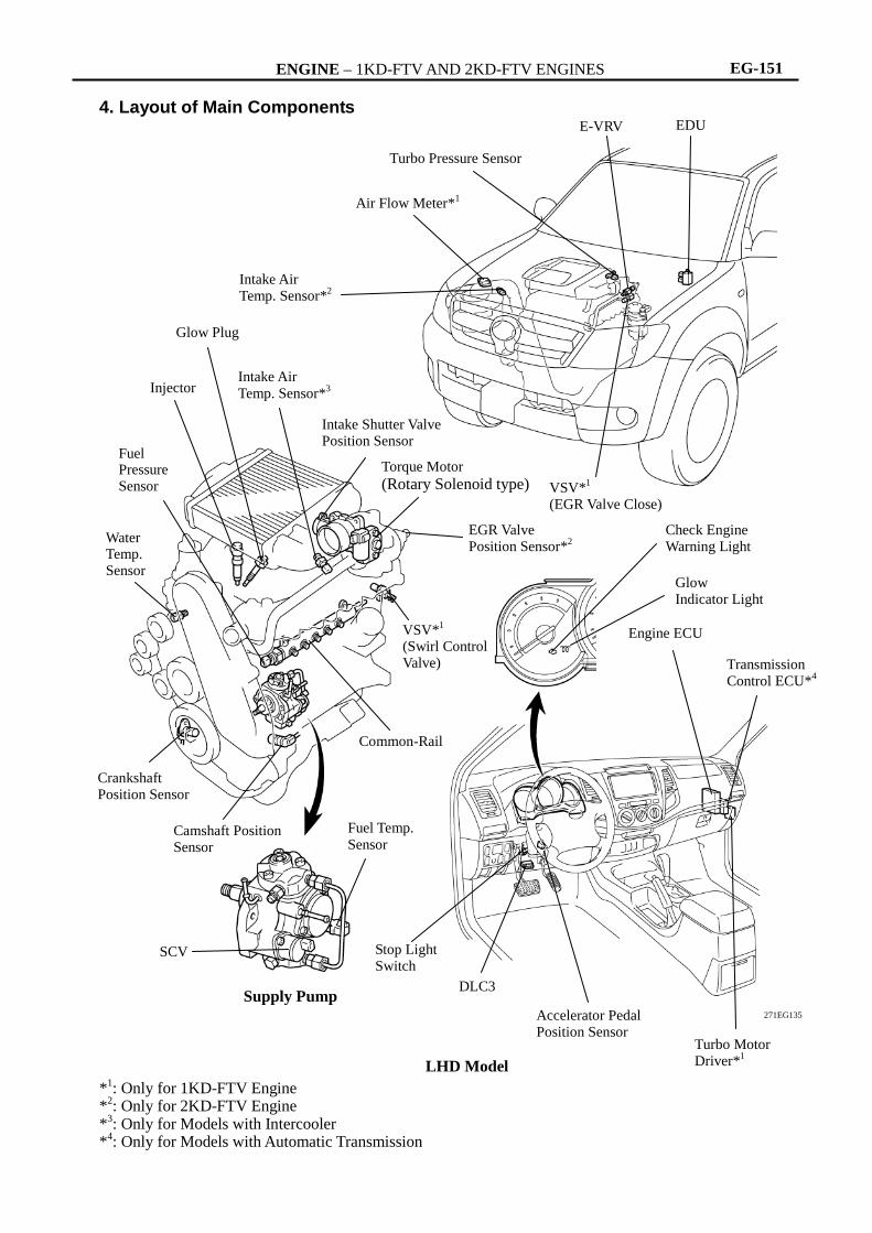
4. Layout of Main Components *
1: Only for 1KD-FTV Engine
*2: Only for 2KD-FTV Engine
*3: Only for Models with Intercooler
*4: Only for Models with Automatic Transmission
Turbo Pressure Sensor
Air Flow Meter*1
Intake Air Temp. Sensor*
2
Intake Shutter Valve Position Sensor
Injector
Glow Plug
Intake Air
Temp. Sensor*3
Torque Motor
(Rotary Solenoid type)
EDU
Water Temp. Sensor
E-VRV
VSV*1
(EGR Valve Close)
Glow Indicator Light
Engine ECU
Check Engine Warning Light
Transmission Control ECU*
4
Turbo Motor Driver*
1
VSV*1
(Swirl Control Valve)
EGR Valve Position Sensor*
2
Common-Rail
Fuel Pressure Sensor
Camshaft Position Sensor
Crankshaft Position Sensor
Fuel Temp.
Sensor
SCV
Supply Pump DLC3
Accelerator Pedal Position Sensor
Stop Light Switch
LHD Model
271EG135

ENGINE – 1KD-FTV AND 2KD-FTV ENGINES EG-152
5. Main Components of Engine Control System General
The main components of the 1KD-FTV and 2KD-FTV engine control system are as follows:
Components Outline Quantity Function
Engine ECU 32-bit CPU 1
The engine ECU effects overall control of the engine control system to suit the operating conditions of the engine in accordance with the signals provided by the sensors.
EDU DC/DC Converter 1
The EDU is used to drive the injector at high speeds. The EDU has realized high-speed driving under high fuel pressure conditions through the use of a DC/DC converter that provides a high voltage, quick- charging system.
Turbo Pressure Sensor
Semiconductor Silicon Chip Type
1 This sensor uses built-in semiconductors to detect the intake manifold pressure.
Atmospheric Pressure Sensor
Semiconductor Silicon Chip Type
1 This sensor, which is built into the engine ECU, uses semiconductors to detect the atmospheric pressure.
Fuel Pressure Sensor Semiconductor
Strain Gauge Type 1
This sensor uses built-in semiconductors to detect the internal pressure of the common-rail.
Crankshaft Position Sensor
Pick-up Coil Type (Rotor Teeth /36-2)
1 This sensor detects the engine speed and performs the cylinder identification.
Camshaft Position Sensor
Pick-up Coil Type (Rotor Teeth /5)
1 This sensor performs the cylinder identification.
Air Flow Meter (1KD-FTV Engine)
Hot-wire Type 1 This sensor uses a built-in hot-wire to directly detect the intake air volume.
Water Temperature Sensor
Thermistor Type 1 This sensor detects the engine coolant temperature by means of an internal thermistor.
Intake Air Temperature Sensor
Thermistor Type 1
This sensor, which is provided at the air cleaner outlet, detects the intake air temperature by means of an internal thermistor.
On the 1KD-FTV engine, this sensor is built into the airflow meter.
Intake Air Temperature Sensor (for Intercooler)
Thermistor Type 1 This sensor, which is provided only on the models with an intercooler, detects the intake air temperature past the intercooler.
Fuel Temperature Sensor
Thermistor Type 1 This sensor detects the fuel temperature in the supply pump by means of an internal thermistor.
Intake Shutter Valve Position Sensor
No-contact Type 1 This sensor detects the intake shutter valve (throttle valve) opening angle.
Accelerator Pedal Position Sensor
No-contact Type 1
This sensor detects the amount of pedal effort applied to the accelerator pedal.
The basic construction and operation of this sensor are the same as in the 1TR-FE and 2TR-FE engines. For details, see page EG-46.
EGR Valve Position Sensor (2KD-FTV Engine)
Contact Type 1 This sensor detects the actual amount of the EGR valve opening.
SCV Suction Control Valve
Linear Solenoid Valve
1
The SCV position is controlled by the signals from the ECU, and a fuel volume that suits the SCV position is drawn into the pumping portion (plunger portion).
Injector
8-hole Type (1KD-FTV Engine)
6-hole Type (2KD-FTV Engine)
4
The injector contains a solenoid valve that opens and closes to increase or decrease the pressure in the control chamber. This causes the nozzle needle to open and close the valve, which results in fuel injection.

ENGINE – 1KD-FTV AND 2KD-FTV ENGINES EG-153
Engine ECU
The 32-bit CPU of the engine ECU is used to increase the speed for processing the signals.
Each of the 2KD-FTV engine and the 2KD-FTV High Version engine is equipped with an engine ECU that contains an engine control program that differs from each other. However, both engine models share the same mechanical components.
On the models equipped with the A340E and A340F automatic transmissions, the engine ECU maintains communication with a separate, independent ECT ECU through CAN (Controller Area Network). Thus, engine control is effected in coordination with ECT control.
Turbo Pressure Sensor
The turbo pressure sensor consists of a semiconductor which utilizes the characteristic of a silicon chip that changes its electrical resistance when pressure is applied to it. The sensor converts the intake air pressure into an electrical signal, and sends it to the engine ECU in an amplified form.
Fuel Pressure Sensor
The fuel pressure sensor consists of a semiconductor which utilizes the characteristic of a silicon chip that changes its electrical resistance when pressure is applied to it. This sensor is mounted on the common-rail, outputs a signal that represents the fuel pressure in the common-rail to the engine ECU, in order to constantly regulate the fuel at an optimal pressure.
271EG136
Sensor Unit
Output
Voltage
Intake Manifold Pressure
5
0
(V)
(kPa) 250 100
Detection Portion
271EG137 Fuel Pressure
(MPa)
Output
Voltage
(V)

ENGINE – 1KD-FTV AND 2KD-FTV ENGINES EG-154
Crankshaft Position Sensor and Camshaft Position Sensor
The timing rotor of the crankshaft consists of 34 teeth, with 2 teeth missing. The crankshaft position
sensor outputs the crankshaft rotation signals every 10, and the missing teeth are used to determine the top-dead-center.
To detect the camshaft position, a protrusion that is provided on the timing pulley is used to generate 5 pulse for every 2 revolution of the crankshaft.
Sensor Output Waveforms
Camshaft Position Sensor Camshaft
Position Sensor
5 Pulse/720 CA 34 Pulse/360 CA
224EG41
34 Pulse/360 CA 34 Pulse/360 CA
180 CA 180 CA 180 CA
5 Pulse/720 CA
271EG138

ENGINE – 1KD-FTV AND 2KD-FTV ENGINES EG-155
Intake Shutter Valve Position Sensor The intake shutter valve position sensor is mounted on the intake shutter assembly, to detect the opening angle of the intake shutter valve (throttle valve), the intake shutter valve position sensor converts the magnetic flux density that changes when the magnetic yoke (located on the same axis as the intake shutter valve shaft) rotates around the hall IC into electric signals to operate the intake shutter valve control motor.
258AE62
Magnet
Hall IC
Intake Shutter Valve (Throttle Valve)
271EG82
Intake Shutter Valve Position Ratio (%)
5
0 100
Output Voltage
(V)
271EG83

ENGINE – 1KD-FTV AND 2KD-FTV ENGINES EG-156
6. Fuel Injection Volume Control The engine ECU calculates two types of values: the basic injection volume and the maximum injection volume. Then, the engine ECU compares the basic and maximum injection volumes, and determines the smaller calculated value to be the final injection volume.
Basic Injection Volume
Maximum Injection Volume
*: Only for 1KD-FTV Engine
Accelerator Pedal Position Sensor
Crankshaft Position Sensor
Engine Speed
Calculation of Basic Injection
Volume
ISC* Correction
Water Temp. Sensor
224EG44
Engine ECU
*: Idle Speed Control
Basic/Maximum Injection Volume (Map data inside of ECU)
Maximum Injection Volume Correction
Crankshaft Position Sensor
Engine Speed
Water Temp. Sensor
Fuel Temp. Sensor
Intake Air Temp Sensor
Turbo Pressure Sensor
Air Flow Meter*
Intake Air Volume*
Engine ECU
224EG46

ENGINE – 1KD-FTV AND 2KD-FTV ENGINES EG-157
Final Injection Volume Decision
7. Fuel Injection Timing Control Fuel injection timing is controlled as shown below.
Engine ECU
Basic Injection Volume
Maximum Injection Volume
Comparison
Fuel Pressure
Final EDU
Injector
224EG48
Accelerator Pedal Position Sensor
Crankshaft Position Sensor Engine Speed
Basic Injection Timing
Engine ECU
Injection Timing
Correction
Water Temp. Sensor
Intake Air Temp. Sensor
Turbo Pressure Sensor
EDU Injection
201EG45

ENGINE – 1KD-FTV AND 2KD-FTV ENGINES EG-158
8. During Starting Control Injection Volume Control
The starting injection volume is determined by adjusting the basic injection volume in accordance with the starter ON signals (ON time) and coolant temperature sensor signals and engine speed signal. When the engine is cold, the coolant temperature will be lower and the injection volume will be greater.
Injection Timing Control
To determine the starting injection timing, the target injection timing is corrected in accordance with the starter signals, water temperature, and engine speed. When the water temperature is low, if the engine speed is high, the injection timing is advanced.
Basic Injection Volume
Engine ECU
Correction Water Temp. Sensor
224EG50
Crankshaft Position Sensor
Starter Signal +
Target Injection Timing Correction
Engine ECU
Water Temp. Sensor
224EG51
Crankshaft Position Sensor
Starter Signal

ENGINE – 1KD-FTV AND 2KD-FTV ENGINES EG-159
9. Idle Speed Control Fuel injection timing is controlled as shown below.
Target Speed
Calculation
Engine ECU
Water Temp. Sensor
233EG14
Crankshaft Position Sensor
Starter Signal
Accelerator Pedal Position Sensor
A/C Signal*
Injection Volume Correction
Comparison
Actual Engine Speed
Vehicle Speed Sensor
Idle-up Signal
*: with Air Conditioner

ENGINE – 1KD-FTV AND 2KD-FTV ENGINES EG-160
10. Fuel Pressure Control General
Engine ECU calculates the target injection pressure (32~160MPa/1KD-FTV, 30~160MPa/2KD-FTV) base on the engine conditions, that are the signals from the acceleration pedal position sensor and the crankshaft position sensor. To control fuel pressure, signals sent to SCV (Suction Control valve) of the supply pump regulate the pumping volume, so that the pressure detected by the pressure sensor matches the target injection pressure.
Supply Pump
SCV
Fuel Temp. Sensor
EDU
Calculation of target injection
pressure
Engine ECU
Crankshaft Position
Sensor
Accelerator Pedal Position Sensor
Injector
Common-rail
Fuel Pressure Sensor Pressure Limiter
271EG139

ENGINE – 1KD-FTV AND 2KD-FTV ENGINES EG-161
System Operation 1) General The engine ECU controls the opening of the SCV in order to regulate the volume of fuel that is pumped by the supply pump to the common-rail. Consequently, the fuel pressure in the common-rail is controlled to the target injection pressure.
2) SCV Opening Small (a) When the opening of the SCV is small, the fuel suction area is kept small, which decrease the
transferable fuel quantity. (b) The plunger strokes fully, however, the suction volume becomes small due to the small suction area.
Therefore, the difference of the volume between the geometry volume and the suction volume is in vacuum condition.
(c) Pumping will start at the time when the fuel pressure has become higher than the common-rail pressure.
Plunger TDC
(a)
245EG13
Pumping Starting Point Plunger BDC
(b) (c)
SCV
Small Suction Area
Fuel Pumping Mass
Cam Stroke

ENGINE – 1KD-FTV AND 2KD-FTV ENGINES EG-162
3) SCV Opening Large (a) When the opening of the SCV is large, the fuel suction area is kept large, which increase the
transferable fuel quantity. (b) If the plunger strokes fully, the suction volume will increase because the suction area is large. (c) Pumping will start at the time when the fuel pressure has become higher than the common-rail
pressure.
Cam Stroke
(a) (b) (c)
Large Suction Area
Pumping Starting Point
245EG14
Fuel Pumping Mass

ENGINE – 1KD-FTV AND 2KD-FTV ENGINES EG-163
11. Pilot Injection Control Pilot injection is a method that provides an auxiliary fuel injection before the main fuel injection takes
place. The purpose of pilot injection is to gently start the combustion of the fuel of the main injection in order to reduce combustion noise.
During pilot injection, the pilot injection volume, timing, and interval (Between pilot injection and main injection) are controlled as shown below.
State
Fuel Injection
Combustion Pressure
Pilot Injection Ordinarily Injection
Pilot Injection Main Injection
168EG23
Accelerator Pedal Position Sensor
Crankshaft Position Sensor Engine Speed
Engine ECU
Basic Pilot Injection (Volume, Timing, Interval)
201EG45
Pilot Injection (Volume, Timing, Interval)
Correction
Intake Air Temp. Sensor
Water Temp. Sensor
Turbo Pressure Sensor
EDU Injection

ENGINE – 1KD-FTV AND 2KD-FTV ENGINES EG-164
12. Intake Shutter Control The opening of the intake shutter valve (throttle valve) that is installed on the intake manifold is controlled by the engine ECU in accordance with engine condition. As a result, the noise that is generated during idling and deceleration, as well as the noise and vibration that are generated when the engine is stopped, have been reduced and this control makes it possible to re-circulate the exhaust gas in accordance with the driving condition.
13. Swirl Control (Only for 1KD-FTV Engine) The engine ECU determines the swirl control valve position (open or closed) based on the engine conditions (engine speed and accelerator pedal effort). Then, it switches the vacuum that is applied to the actuator diaphragm via the VSV, in order to open and close the swirl control valve. In the low engine speed range, the engine ECU closes the swirl control valve to strengthen the swirl in the combustion chamber, thus promoting the mixture of fuel and air and stabilizing combustion. When the engine speed increases to the medium or high-speed range, the engine ECU fully opens the swirl control valve. On a cold engine, the engine ECU fully closes the swirl control valve to reduce the amount of white smoke emissions.
Intake Shutter Valve Control Motor
Engine ECU
Engine Speed
Water Temp.
Accelerator Pedal Position
Intake Air Pressure
Intake Air Temp.
Ignition Switch
271EG140
Intake Shutter Valve Position
Sensor
Intake Shutter
Valve
Vehicle Speed
Intake Port
Combustion Chamber
Actuator
Swirl Control Valve
Vacuum Pump
VSV
Engine ECU
Engine Speed
Accelerator Pedal Position
271EG90

ENGINE – 1KD-FTV AND 2KD-FTV ENGINES EG-165
14. Turbo Charger Control (Only for 1KD-FTV Engine) General
The engine ECU controls the nozzle vane position using the turbo motor driver, in order to obtain the
calculated target turbo pressure appropriate to the engine operating condition.
The engine ECU calculates the optimal nozzle vane position in accordance with the driving conditions (engine speed, injection volume, atmospheric pressure, and water temperature etc), and sends a target nozzle vane position signal to the turbo motor driver. The turbo motor driver controls the nozzle vane position in accordance with this signal and the actual nozzle vane position signal provided by the nozzle vane position sensor.
Crankshaft Position Sensor
DC Motor Turbo Pressure Sensor
Injector
Water Temp. Sensor
Intake Air Temp. Sensor
Nozzle Vane Position Sensor
Turbo Motor
Driver
Engine ECU
Actual Nozzle Vane Position
Nozzle Vane Position Control
Target Nozzle Vane Position Signal
Turbocharger Control Status
Atmospheric Pressure Sensor
271EG141

ENGINE – 1KD-FTV AND 2KD-FTV ENGINES EG-166
Construction
1) General
Variable nozzle vane device is established on the turbine (exhaust) side, and consisted of a DC motor, nozzle vane position sensor, linkage, drive arm, unison ring, driven arms and nozzle vanes.
To control the nozzle vane position, the turbo motor driver renders the contact position of the linkage with the full-close stopper (thus fully closing the nozzle vane) as the zero point for the nozzle vane position sensor.
If the turbocharger has been reinstalled or replaced, turn the ignition switch from ON to OFF once, and make sure that the linkage comes in contact with the full-close stopper.
The full-close stopper position, which is adjusted at the factory at the time of shipment, is not serviceable in the field. For this reason, if the linkage does not come in contact with the full-close stopper during an inspection, the turbocharger assembly must be replaced. Never attempt to loosen or tighten the locknut of the full-close stopper because it will adversely affect the performance of the engine.
For details, see the Hilux Repair Manual.
Service Tip
DC Motor
Nozzle Vane
Position Sensor
Linkage
Driven Arm Unison Ring
Nozzle Vane
Turbine Wheel
Drive Arm
Full-Close Stopper
271EG142
271EG143
Open
Close
Full-Close
Stopper
Lock Nut
Linkage
ENGINE – 1KD-FTV AND 2KD-FTV ENGINES EG-167
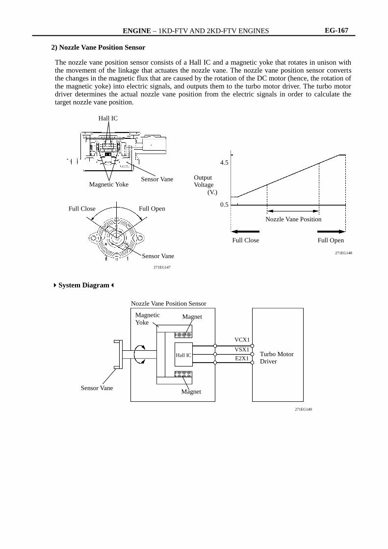
2) Nozzle Vane Position Sensor
The nozzle vane position sensor consists of a Hall IC and a magnetic yoke that rotates in unison with the movement of the linkage that actuates the nozzle vane. The nozzle vane position sensor converts the changes in the magnetic flux that are caused by the rotation of the DC motor (hence, the rotation of the magnetic yoke) into electric signals, and outputs them to the turbo motor driver. The turbo motor driver determines the actual nozzle vane position from the electric signals in order to calculate the target nozzle vane position.
System Diagram
Hall IC
Magnetic Yoke Sensor Vane
Sensor Vane
271EG147
Full Close Full Open
4.5
0.5
Full Close Full Open
Nozzle Vane Position
Output Voltage
(V.)
271EG148
Turbo Motor Driver
VCX1
VSX1
E2X1 Hall IC
Magnet
Magnet Magnetic
Yoke
Nozzle Vane Position Sensor
271EG149
Sensor Vane

ENGINE – 1KD-FTV AND 2KD-FTV ENGINES EG-168
Operation
1) At Engine Low Speed Range
When the engine is running in a low speed range, the DC motor presses down the linkage by a signal from the turbo motor driver. The tip of the linkage rotates the unison ring counterclockwise through a drive arm. The unison ring contains a driven arm, which is placed through the cutout portion of the unison ring. This driven arm also moves in the direction of the rotation of the unison ring. The fulcrum of the driven arm is an axis that is integrated with the nozzle vane behind the plate. When the driven arm moves counterclockwise, the nozzle vane moves toward the closing direction. This results in increasing the velocity of the exhaust gas flowing to the turbine, as well as the speed of the turbine. As a result, torque is improved when the engine is running at low speeds.
2) At Engine Medium-to-High Speed Range
When the engine is running in a medium-to-high speed range, the DC motor pulls up the linkage by a signal from the turbo motor driver. With this, the driven arm moves clockwise and this opens the nozzle vane and holds the specified supercharging pressure. Thus, lowering the back pressure and improving the output and fuel consumption.
Nozzle Vane
DC Motor
Drive Arm
Fulcrum
Plate
Linkage
Unison Ring
271EG144
Gas Flow
Driven Arm Driven Arm
Cutout Portion
Linkage
271EG145
ENGINE – 1KD-FTV AND 2KD-FTV ENGINES EG-169
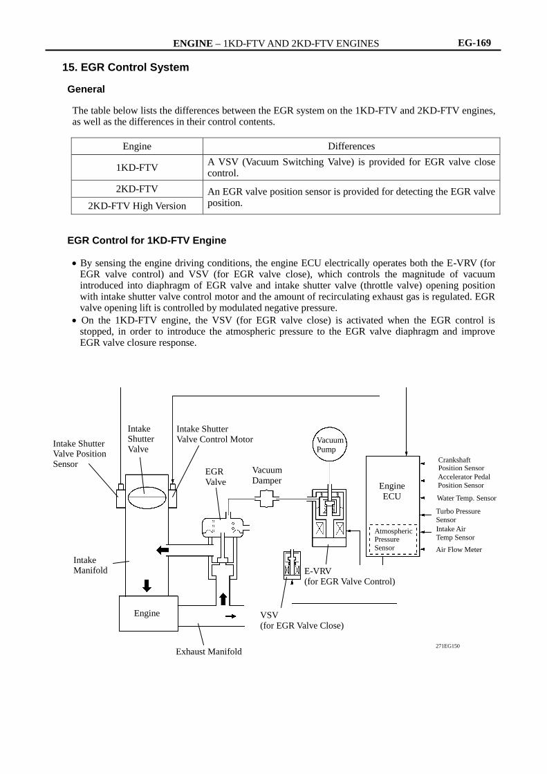
15. EGR Control System General
The table below lists the differences between the EGR system on the 1KD-FTV and 2KD-FTV engines, as well as the differences in their control contents.
Engine Differences
1KD-FTV A VSV (Vacuum Switching Valve) is provided for EGR valve close control.
2KD-FTV An EGR valve position sensor is provided for detecting the EGR valve position. 2KD-FTV High Version
EGR Control for 1KD-FTV Engine
By sensing the engine driving conditions, the engine ECU electrically operates both the E-VRV (for
EGR valve control) and VSV (for EGR valve close), which controls the magnitude of vacuum introduced into diaphragm of EGR valve and intake shutter valve (throttle valve) opening position with intake shutter valve control motor and the amount of recirculating exhaust gas is regulated. EGR valve opening lift is controlled by modulated negative pressure.
On the 1KD-FTV engine, the VSV (for EGR valve close) is activated when the EGR control is stopped, in order to introduce the atmospheric pressure to the EGR valve diaphragm and improve EGR valve closure response.
Intake Shutter Valve
Intake Manifold
Engine
Exhaust Manifold
Intake Shutter Valve Control Motor
EGR
Valve
Vacuum
Damper
E-VRV (for EGR Valve Control)
Vacuum Pump
Engine
ECU
Crankshaft Position Sensor
Accelerator Pedal
Position Sensor
Turbo Pressure
Sensor
Water Temp. Sensor
271EG150
Intake Air
Temp Sensor
Intake Shutter Valve Position Sensor
Atmospheric Pressure
Sensor Air Flow Meter
VSV
(for EGR Valve Close)

ENGINE – 1KD-FTV AND 2KD-FTV ENGINES EG-170
EGR Control for 2KD-FTV Engine
By sensing the engine driving conditions and actual amount of EGR valve opening, the engine ECU electrically operates the E-VRV (for EGR valve control), which controls the magnitude of vacuum introduced into diaphragm of EGR valve and intake shutter valve (throttle valve) opening position with intake shutter valve control motor and the amount of recirculating exhaust gas is regulated. EGR valve opening lift is controlled by modulated negative pressure.
Intake Shutter Valve
Intake
Manifold
Engine
Exhaust Manifold
Intake Shutter Valve Control Motor
EGR
Valve
Vacuum
Damper
E-VRV
(for EGR Valve Control)
Vacuum Pump
Engine
ECU
Crankshaft Position Sensor
Accelerator Pedal
Position Sensor
Turbo Pressure
Sensor
Water Temp.
Sensor
271EG131
Intake Air
Temp Sensor
EGR Valve Position Sensor
Intake Shutter Valve Position Sensor
Atmospheric Pressure Sensor

ENGINE – 1KD-FTV AND 2KD-FTV ENGINES EG-171
16. Diagnosis
The diagnosis system of the 1KD-FTV and 2KD-FTV engines uses the M-OBD (Multiplex On-Board Diagnosis).
When the Engine ECU detects a malfunction, the engine ECU makes a diagnosis and memorizes the failed section. Furthermore, the check engine warning light in the combination meter illuminates or blinks to inform the driver.
The 2-digit DTCs (Diagnostic Trouble Codes) can be accessed by connecting the SST (09843-18040) to the DLC3 terminals TC and CG, and reading the blinking of the check engine warning light.
By using the intelligent tester II, the 5-digit DTCs and ECU data can be read out. Moreover, the ACTIVE TEST can be used to drive the actuator by means of the intelligent tester II.
The Engine ECU can output freeze-frame data to the intelligent tester II. This data is stored in the engine ECU at the very moment when the engine ECU has detected its last data of malfunction.
All the DTCs have been made to correspond to the SAE controlled codes. Some of the DTCs have been further divided into smaller detection areas than in the past, and new DTCs have been assigned to them.
For details, see the Hilux Repair Manual. To clear the DTC that is stored in the engine ECU, use a intelligent tester II or disconnect the battery
terminal or remove the EFI fuse for 1 minute or longer.
17. Fail-Safe
When a malfunction is detected by any of the sensors, there is a possibility of an engine or other malfunction occurring if the ECU were to continue to control the engine control system in the normal way. To prevent such a problem, the fail-safe function of the ECU either relies on the data stored in memory to allow the engine control system to continue operating, or stops the engine if a hazard is anticipated. For details, see the Hilux Repair Manual.
Service Tip
Top Related