


Languages
Pages
Legal


Computer Assisted Orthopaedic and Trauma Surgery
Niels W.L. Schep
Niels Schep BW 1 12-09-2003, 11:56:45

Publication of this thesis was supported by:
Anna-Fonds LeidenArsis MedicalJohnson en JohnsonMathysMedivisionMedtronicNederlandse Vereniging van TraumatologieOrthomedPhilipsSomas
Copyright© 2003 By N.W.L. Schep
printed by: Optima Grafi sche Communicatie Rotterdam
Afbeelding voorkant: Messing sextant midden negentiende eeuw. Gebruikt voor maritieme navigatie.
Afbeelding achterkant: Droge kompasroos, H. Olland, Utrecht, naar een ontwerp van F.J. Kaiser.
Beide objecten maken deel uit van de collectie van het Maritiem Museum in Rotterdam
ISBN 30-6734-030-8
Niels Schep BW 2 12-09-2003, 11:56:45

Computer Assisted Orthopaedic and Trauma Surgery
Computer geassisteerde chirurgie in de orthopedie en de traumatologie
(met een samenvatting in het Nederlands)
Proefschrift
Ter verkrijging van de graad van doctor aan de Universiteit van Utrecht op gezag van de
Rector Magnifi cus,
Prof.dr. W.H. Gispen,
Ingevolge het besluit van het college voor Promoties
In het openbaar te verdedigen op donderdag 16 oktober 2003 des middags te 14.30 uur
door
Niels Willem Luitzen SchepGeboren op 22 januari 1972 te IJsselstein
Niels Schep BW 3 12-09-2003, 11:56:46

Niels Schep BW 4 12-09-2003, 11:56:46

Promotor : Prof. Dr. Chr. van der Werken
afdeling Heelkunde, Faculteit Geneeskunde,
Universiteit Utrecht
Co-promotor : Dr. I.A.M.J. Broeders
afdeling Heelkunde, Faculteit Geneeskunde,
Universiteit Utrecht
Niels Schep BW 5 12-09-2003, 11:56:46

Niels Schep BW 6 12-09-2003, 11:56:46

CONTENTS
Chapter 1 Introduction and aim of the thesis. 9
Chapter 2 Computer assisted orthopedic and trauma surgery. 15State of the art and future perspectives.Injury 2003 ; 34: 299-306.
Chapter 3 Validation of fl uoroscopy based navigation in the hip region. 31What you see is what you get?Computer Aided Surgery 2002 ; 7: 279-283.
Chapter 4 Validation of computer assisted anteversion and length control
in closed nailing of femoral shaft fractures.
43
Submitted to Der Unfallchirurg.
Chapter 5 Virtual planning of anterior cruciate ligament insertion. 57Validation of a new technique.Submitted to Arthroscopy.
Chapter 6 Internal fi xation of femoral neck fractures with computer
assisted surgery.
71
A report on fi rst cases.European Journal of Trauma in press.
Chapter 7 Computer assisted versus conventional surgery for insertion of
96 cannulated iliosacral screws.
83
Submitted to Journal of Trauma.
Chapter 8 General discussion and conclusions 95Samenvatting en conclusies 107Dankwoord 117Curriculum Vitae 122
Niels Schep BW 7 12-09-2003, 11:56:46

Niels Schep BW 8 12-09-2003, 11:56:46

Introduction and aim of the thesis
1Chapter
Niels Schep BW 9 12-09-2003, 11:56:47

Niels Schep BW 10 12-09-2003, 11:56:47

11
Introduction and aim of the thesis
Introduction
When pilots land an airplane on a landing strip they depend for an important part on their
direct eyesight for orientation. If bad whether conditions decrease their visibility they
have to rely on their instruments for orientation in order to land safely. Minimal invasive
trauma and orthopaedic surgery can be compared by fl ying in thick fog, because the surgeon
performs the operation through small incisions. Consequently, direct sight on the operation
area and therefore on their instrument position is impossible. In these situations surgeons
must rely on radiographic imaging techniques like computer tomography (CT), magnetic
resonance imaging (MRI) and fl uoroscopy for orientation.
Drawback of these imaging techniques is that instrument positions are only shown at
one particular moment, the moment of actual imaging. Continuous imaging is technically
complex and leads to a signifi cant radiation exposure for both patient and surgical team.
(1-3) In between imaging the surgeon has to rely on three-dimensional (3D) orientation
and expert knowledge of the anatomy for instrument navigation. This situation may lead to
inaccuracy and consequently operation related morbidity. Moreover, the lack of continuous
visualisation may infl uence the reproducibility of surgical treatment, performing identical
procedures.
To create an environment where surgeons receive real-time feedback about their instrument
position, computer technologies were integrated in surgical procedures. This type of surgical
technology is referred to as Computer Assisted Surgery (CAS). CAS offers the possibility
to continuously monitor the position of surgical instruments in relation to the patient’s
anatomy intraoperatively. Therefore, the position of surgical instruments is superimposed
virtually on single shot radiographic images in real time. This concept is analogous with
a global positioning system (GPS) used for navigation. Pre- or intra-operatively obtained
radiographic images act as the roadmap in which the position of a surgical instrument can
be monitored virtually.
Potential advantages of CAS are improvement of accuracy and reproducibility of surgical
procedures due to the fact that surgical instruments are guided by real time navigation. This
may lead to less morbidity combined with a strong reduction of radiation exposure for both
patient and surgical team.
The goal of this thesis was to evaluate the hypothesis of improved accuracy and reproducibility
of surgical procedures using CAS. This was achieved by performing a series of tests. All these
tests were performed within an experimental or clinical setting. To test the hypothesis the
following questions were answered.
Niels Schep BW 11 12-09-2003, 11:56:47

12
Chapter 1
1. How exact represents the displayed position of an instrument in fl uoroscopic images the
real situation ?
2. Does CAS reduce surgical variance and therewith improve the reproducibility of (minimal
invasive) orthopaedic and trauma surgery ?
3. Are there clinical benefi ts using CAS during positioning of implants?
Niels Schep BW 12 12-09-2003, 11:56:48

13
Introduction and aim of the thesis
Reference List
1. Madan, S. and Blakeway, C.: Radiation exposure to surgeon and patient in intramedullary nailing of the lower limb. Injury. 33:723, 2002.
2. Mehlman, C. T. and DiPasquale, T. G.: Radiation exposure to the orthopaedic surgical team during fl uoroscopy: “how far away is far enough?”. J. Orthop Trauma. 11:392-398, 1997.
3. Rampersaud, Y. R., Foley, K. T., Shen, A. C., Williams, S., and Solomito, M.: Radiation exposure to the spine surgeon during fl uoroscopically assisted pedicle screw insertion. Spine. 25:2637-2645, 2000.
Niels Schep BW 13 12-09-2003, 11:56:48

Niels Schep BW 14 12-09-2003, 11:56:49

Computer assisted orthopaedic and trauma surgery
2Chapter
Injury 2003 ; 34: 299-306.
N.W.L. Schep, I.A.M.J. Broeders and Chr. van der Werken
Department of Surgery
University Medical Centre Utrecht, The Netherlands
Niels Schep BW 15 12-09-2003, 11:56:49

Niels Schep BW 16 12-09-2003, 11:56:49
17
Computer assisted orthopaedic and trauma surgery
Summary
The recent years computer technologies are more and more integrated in surgical procedures.
The potential advantages of computer assisted surgery (CAS) are: increase of accuracy of
surgical interventions, less invasive operations, better planning and simulation and reduction of
radiation exposure for both patient and surgeon. After introduction of CAS in neurosurgery, the
clinical applications of this technique expanded also in trauma and orthopaedic surgery. The
fi rst application of this new technique in orthopaedic and trauma surgery was for placement of
lumbar pedicle screws. After the introduction in spine surgery CAS was applied in other fi elds
of orthopaedic surgery like hip, knee and skeletal trauma surgery. In this article the technical
background and the various clinical applications of computer assisted orthopaedic and trauma
surgery are outlined.
Niels Schep BW 17 12-09-2003, 11:56:49

Niels Schep BW 18 12-09-2003, 11:56:50
19
Computer assisted orthopaedic and trauma surgery
Introduction
Computer technologies were introduced into surgical practice for preoperative planning and
to enhance accuracy and safety for a variety of procedures. This new technology -so called
Computer Assisted Surgery (CAS)- was initiated in neurosurgery and focused on preoperative
planning and increased intra-operative accuracy. Neurosurgeons used this technique to
facilitate intracranial needle biopsies, isotope implantation and tumor resection. (1;2;10;40;45)
For many years, only standard radiographic images including CT- and MRI- scans were used
for preoperative planning. With the introduction of more complex surgical procedures,
surgeons required better visualisation and manipulation of complex anatomy, pre- or intra-
operatively, in an interactive way.
As part of CAS the surgeon is able to manipulate radiographic images during pre-operative
planning. Subsequently, a link is made between the preoperative plan and the actual
procedure. Technical adjustments of surgical instruments and the operating theatre enable
surgeons to continuously monitor the position of instruments in relation to the patient’s
anatomy and the preoperative plan. Intra-operatively the position of the surgical instruments
is superimposed in pre- or intra-operatively obtained images such as fl uoroscopy, MRI- or
CT scan.
The possible advantages are an increase in accuracy of surgical procedures due to “real time”
navigation by a less invasive approach, less time-consuming interventions because of better
planning and simulation and fi nally reduction of radiation exposure for both patient and
surgeon.
An important problem during CAS is the continuous intra-operative change of anatomy
caused by manipulation by the surgeon. Bone tissue, however, is almost not deformable
and therefore is very suitable for CAS, based on pre- or intra-operatively obtained images.
For this reason, after introduction of CAS in neurosurgery, the clinical applications of this
technique expanded also in trauma and orthopaedic surgery. In this article the technical
background and the various clinical applications of computer assisted orthopaedic and
trauma surgery are outlined.
Working with CAS
CAS can be applied in the operating theatre only, but may be preceded by a preoperative
workup, including planning and/or simulation. Preoperative planning is based on processing
of available images such as CT and MRI scans. 3-D images are often computed at this stage
Niels Schep BW 19 12-09-2003, 11:56:50
of the procedure, and length or volumetric measurements may be conducted. With this
information the surgeon can create a pre-operative plan for the optimal surgical procedure.
This plan may be tested while simulating techniques, in which the skin incision, the approach
to the target, the cut surfaces and the position of implants are evaluated. Simulation can also
play an important role in training and education of residents and inexperienced surgeons.
The image data, including the validated pre-operative workup are subsequently loaded on an
OR workstation to enable image guided surgery exactly as planned. For routinely performed
procedures, straightforward planning such as determination of entry points or access routes
can be performed on the spot.
During CAS the position of the surgical instruments and the implants are displayed on a
computer screen in relation to the patient’s anatomy. For this purpose position tracking and
registration are required. (6;8;28;43)
Instruments and position tracking
The system can be compared with a global positioning system (GPS) used for automobile
navigation. Here the surgical instrument is replaced by the car; the driver can see the virtual
position of the car on a roadmap on a digital screen. In surgical navigation pre- or intra-
operatively obtained digital radiographic images act as the roadmap.
A key element in surgical navigation is the tracking sensor, which identifi es the instruments
in order to determine their position. In the example of the GPS the tracking sensor is a
satellite, which monitors the vehicle’s position using signals transmitted by the navigation
system in the car. Surgical tracking systems use magnetic, acoustic or optical signals for
localising a target within the operating room. The most commonly used technique is optical
tracking by (infrared) light emitting diodes (LEDs) or passive markers such as retro-refl ective
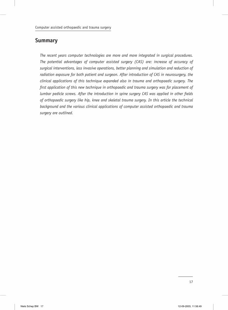
spheres or disks. Shields with at least two but usually four or six LEDs/passive markers are
attached to the instruments and the operated bone. (Figure1)
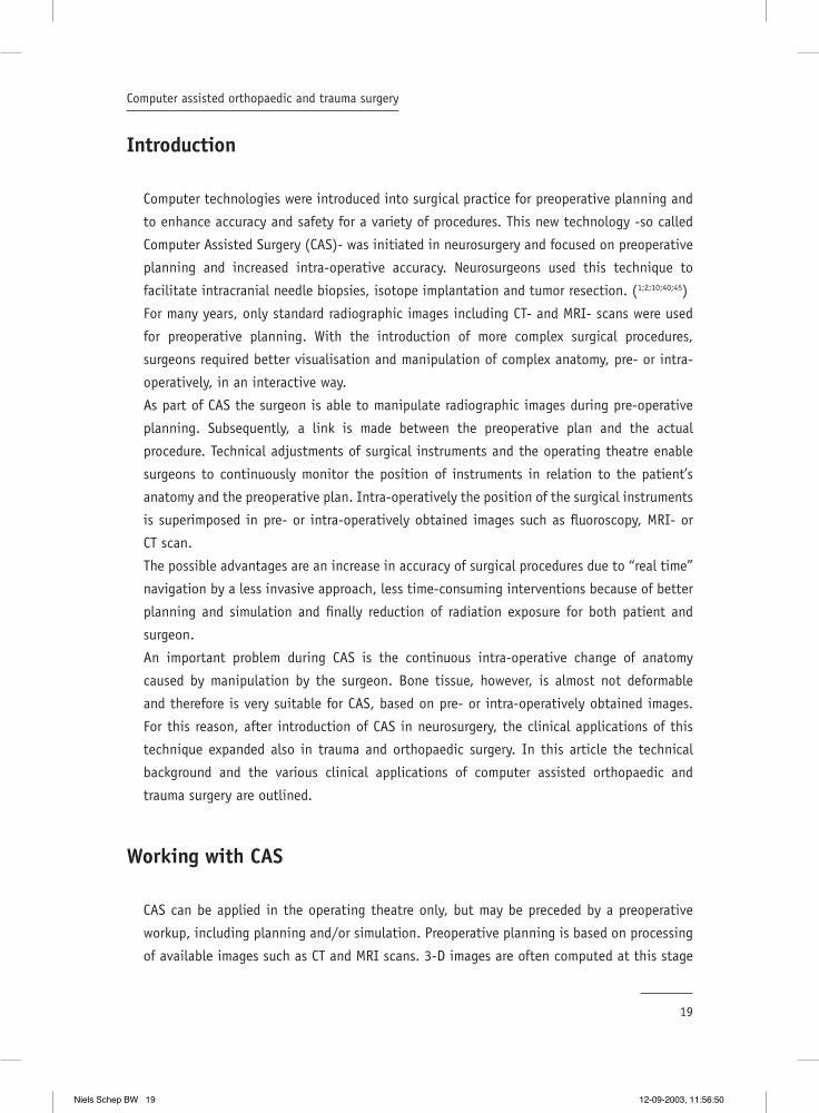
To allow freedom of movement of the operation fi eld during surgery, the position of the target
bone also has to be tracked. Therefore, a frame with LEDs or passive markers is attached to
the skeleton, the so-called dynamic reference frame (DRF). The tracking sensor overlooking
the surgical fi eld receives the signals emitted by the LEDs/passive markers of both the DRF
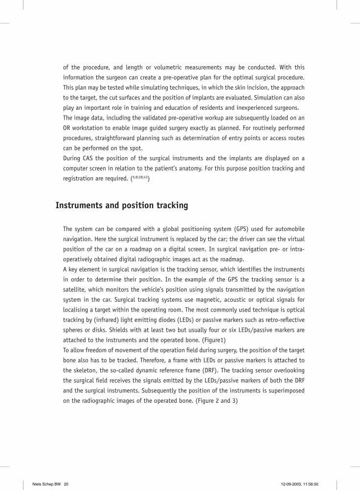
and the surgical instruments. Subsequently the position of the instruments is superimposed
on the radiographic images of the operated bone. (Figure 2 and 3)
Niels Schep BW 20 12-09-2003, 11:56:50
21
Computer assisted orthopaedic and trauma surgery
FIGURE 1LEDs attached to surgical instruments and a dynamic reference frame (DRF) attached to a femur.
FIGURE 2an optical tracker tracks the position of the target bone.
FIGURE 3the position of the surgical instrument is superimposed in a pre-operative CT-scan of a vertebra in pedicle screw placement.
Niels Schep BW 21 12-09-2003, 11:56:51
22
Chapter 2
Registration of preoperatively obtained radiographic images
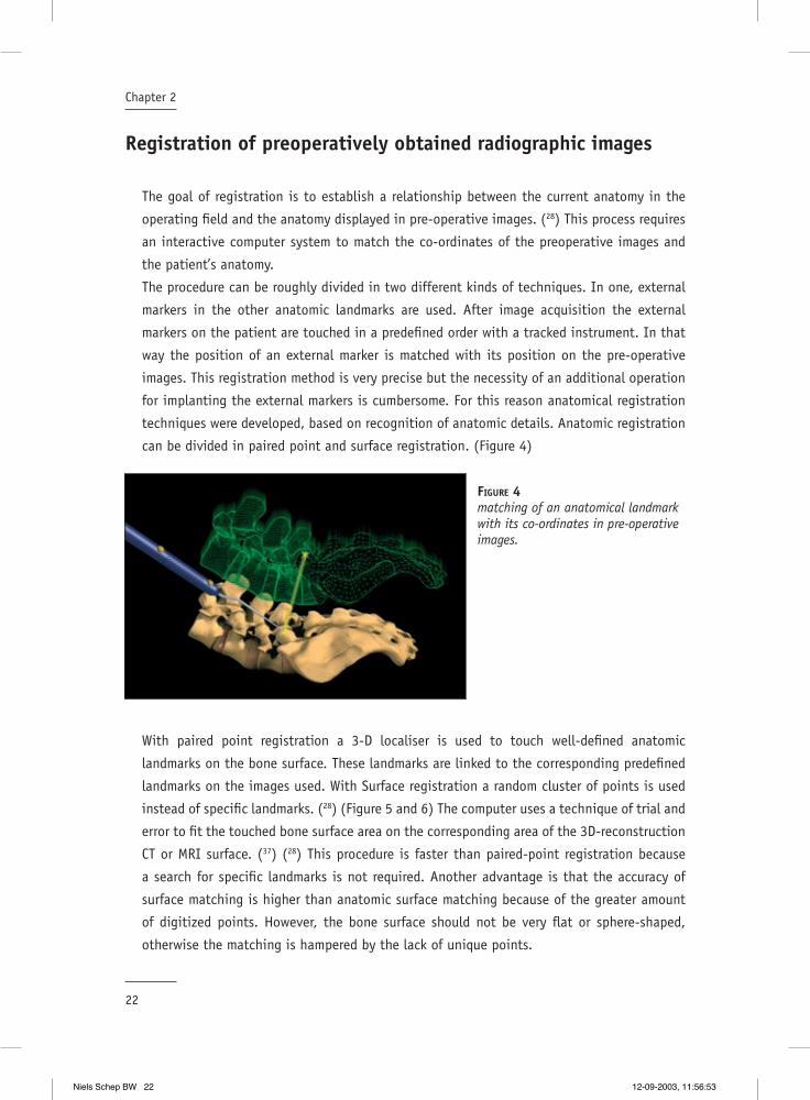
The goal of registration is to establish a relationship between the current anatomy in the
operating fi eld and the anatomy displayed in pre-operative images. (28) This process requires
an interactive computer system to match the co-ordinates of the preoperative images and
the patient’s anatomy.
The procedure can be roughly divided in two different kinds of techniques. In one, external
markers in the other anatomic landmarks are used. After image acquisition the external
markers on the patient are touched in a predefi ned order with a tracked instrument. In that
way the position of an external marker is matched with its position on the pre-operative
images. This registration method is very precise but the necessity of an additional operation
for implanting the external markers is cumbersome. For this reason anatomical registration
techniques were developed, based on recognition of anatomic details. Anatomic registration
can be divided in paired point and surface registration. (Figure 4)
With paired point registration a 3-D localiser is used to touch well-defi ned anatomic
landmarks on the bone surface. These landmarks are linked to the corresponding predefi ned
landmarks on the images used. With Surface registration a random cluster of points is used
instead of specifi c landmarks. (28) (Figure 5 and 6) The computer uses a technique of trial and
error to fi t the touched bone surface area on the corresponding area of the 3D-reconstruction
CT or MRI surface. (37) (28) This procedure is faster than paired-point registration because
a search for specifi c landmarks is not required. Another advantage is that the accuracy of
surface matching is higher than anatomic surface matching because of the greater amount
of digitized points. However, the bone surface should not be very fl at or sphere-shaped,
otherwise the matching is hampered by the lack of unique points.
FIGURE 4matching of an anatomical landmark with its co-ordinates in pre-operative images.
Niels Schep BW 22 12-09-2003, 11:56:53

23
Computer assisted orthopaedic and trauma surgery
Recently ultrasound has been introduced to obtain non-invasive surface registration. The
position of the ultrasound probe is tracked and the collection of 3-D surface points is
matched with a 3-D pre-operative CT or MRI image. (41)
The latest development in non-invasive surface registration is the use of laser beams. The
distance between a laser source and skin or exposed target surface is measured. The surgeon
moves the laser over the surface of the target area, while a tracking sensor records the
position of the laser source. In this way the system obtains a surface map of the collection
of all laser points. Registration is done by matching the surface map to the surface of the
3-D model derived from existing images. (Figure 7)
FIGURE 5the processus spinosus, both processi transversus and a point in between are registered.
FIGURE 6principles of surface matching.
FIGURE 7non-invasive surface registration with a laser
Niels Schep BW 23 12-09-2003, 11:56:56

24
Chapter 2
Navigation within intra-operatively obtained images
When intra-operatively acquired images are used for navigation, a manual registration
procedure can be avoided by tracking both the target and the imaging device. A sophisticated
technique described by Jacob et al. is image-guided surgery with a CT scanner available in
the operating room. While the patient is fi xed fi rmly to the CT table, the position of the
table relative to the CT scanner is recognized by the computer, providing exact orientation
in targets fi xed to the scanner table. An optical tracker attached to the ceiling above the CT
scan detects the position of the instruments. Subsequently the position of the instruments
is superimposed on the CT scans. (15) These procedures are also described with the use of
MRI scans. (3)
Generally however, fl uoroscopy is used for navigation in intra-operatively acquired images.
Advantages of this specifi c imaging modality are cost-effectiveness, general availability of
C-arm systems, fl exibility, ease of use and low radiation exposure. To combine fl uoroscopy
with navigation technology, the C-arm is equipped with a LED shield. This shield allows the
C-arm to be detected by the tracking sensor. (14) After image acquisition with the navigated
C-arm, the exact position of the tracked instruments is displayed in the fl uoroscopy images.
(Figure 8)
FIGURE 8the pedicle awl is displayed in fl uoroscopic images of sawbone spine during pedicle screw placement.
Niels Schep BW 24 12-09-2003, 11:56:57

25
Computer assisted orthopaedic and trauma surgery
Clinical applications of CAS
The fi rst application of CAS in orthopaedic and trauma surgery was for placement of lumbar
pedicle screws. Transpedicle fi xation is used in a variety of spine operations, including
treatment of scoliosis, spondylolisthesis, fractures and instability. The rationale for using
navigation technology in pedicle screw placement was an incidence of incorrect placement
of the screws under fl uoroscopy guidance, ranging from 10-40%. (27) In 1995 Nolte et al.
published an in vitro set up, drilling pedicle holes in lumbar vertebrae. The technique
combined CT imaging with intra-operative navigation. For registration they used both surface
and paired point matching. (30) Since 1995 many authors have reported clinical series on
computer assisted CT based pedicle screw insertion. Schlenzka et al. assessed the accuracy
of insertion of 139 screws by means of post-operative CT scans. With 133 (95,7%) positioned
in the pedicle. (28;35) Other authors reported that CAS pedicle screw placement is an accurate,
reproducible and safe procedure. The pedicle perforation rate in screws implanted with CAS
ranges between 4- and 15%. (18;22;25-27;36)
CAS pedicle screw placement with fl uoroscopy based navigation is described by Nolte et al.
for the fi rst time. A prospective study to determine the accuracy of pedicle screw insertion
using C-arm based navigation was done by Fritsch et al. Of the 66 screws inserted, 63
(95,5%) were placed within the pedicle wall. (9;29) The good results in computer assisted
pedicle screw placement helped introducing CAS in other fi elds of orthopaedic surgery.
In hip surgery, CAS is used to improve the clinical outcome of total hip replacement and
periacetabular osteotomies. Dislocation after total hip replacement (THR) is a common
postoperative complication. Malalignment of prosthetic components is responsible for
a signifi cant number of dislocations, with the acetabular cup being the most likely
to be malpositioned. CAS can be used to facilitate the accuracy of acetabular cup
implantation.(7)
During preoperative planning implant size, location and cup orientation are specifi ed in a
digital 3-D model of the pelvis based on CT-scans. By means of simulating a range of motions
the location and cup orientation are virtually tested. Subsequently the pre-operative plan
is executed under image guidance. These image-guided systems offer improved methods of
orientation measurement and cup placement during total hip replacement surgery.(7;12;16)
Vandevelde et al. described a signifi cant reduction in variability of abduction angles of the
acetabular cup in favor of CAS when compared with conventional technique. (42)
In 1997 Langlotz et al. presented the fi rst 12 cases of computer assisted periacetabular
osteotomies. This operation is used for the treatment of dysplastic hips and consists of a
sequence of cuts performed through the ischium, pubis and ilium using different custom
Niels Schep BW 25 12-09-2003, 11:57:00

26
Chapter 2
osteotomes and an oscillating saw. The acetabulum is completely liberated from the pelvis,
reoriented and fi xated. Preoperatively a CT scan of the complete pelvis was obtained.
Registration was done by anatomical landmarks, fi ducial markers or by surface matching. Al
the surgical instruments were tracked by LED’s. The correction was satisfactory in all hips
with an improvement of the roof angle from 23.5° to 7°. (23;24;28)
In the knee CAS has been used in total knee arthroplasty (TKA) and knee ligament surgery.
Proper rotational and translational alignment of the prosthetic components and the limb are
key factors for the success of TKA and are therefore targets for navigation technology. (44)
In general there are two CAS techniques for improving prosthetic alignment. One technique
calculates the hip, knee and ankle centres by actively moving the optically tracked femur and
tibia through a range of motions. The location of these centres provides the ideal mechanical
axis of the tibia and femur. Subsequently, the position of the navigated cutting block is
displayed relative to the desired position intra-operatively, so the surgeon is able to perform
the bone resections of the distal femur and proximal tibia as planned pre-operatively. (21) The
other CAS method uses 3-D computer models of the femur and tibia, constructed from pre-
operative CT-data. The computer calculates the bone resections that align the mechanical
axis. Intra-operatively the procedure is as described above. (4)
A prospective randomised trial comparing patients with computer assisted total knee
arthroplasty and conventionally operated patients was performed by Saragaglia et al. (33)
In both groups of 25 patients each, the postoperative femoro-tibial angle was measured.
The femoro-tibial angle was between 177° and 183° in 75% of the patients operated
with a conventional procedure and in 84% of the patients operated with CAS. The results
in the computer-assisted group were better but not signifi cantly different. A signifi cant
better result in mechanical axis in 100 computer assisted TKA patients compared to 50
conventionally operated patients was described by Kiefer et al. (19) The ideal mechanical
axes were calculated when the optically tracked limb was moved through a range of motion.
The postoperative mechanical axis in the coronal plane in the CAS group showed a mean
deviation of 0.3° varus, 73% were in the target range of +/- 2.0°, whereas only 40% of the
patients reached this criteria in the conventionally operated group.
In reconstructive knee surgery navigation techniques are applied to improve the reproducibility
of ACL graft placement. When the anterior cruciate ligament (ACL) is disrupted an ACL graft
is attached to the distal femur and proximal tibia. The problem is that reliable intra-articular
landmarks for accurately positioning the graft hardly exist. This may result in malpositioning
of the graft, resulting in impingement and non ideal elongation patterns.
Navigation systems can add pre- and intra-operative virtual reality feedback to ACL
reconstruction. In that way the surgeon is able to determine the perfect femoral and
Niels Schep BW 26 12-09-2003, 11:57:01
27
Computer assisted orthopaedic and trauma surgery
tibial tunnels in order to avoid impingement. Several authors described computer assisted
ACL replacement based on radiographic images. (20;31;32) These systems reduced the graft
placement variability but did not offer the possibility of simulation under movement. Non-
radiographic images based CAS in ACL reconstruction was presented by Dessenne et al. Two
rigid dynamic reference bases (LED’s) were attached to the femur and the tibia to track
their positions. Predefi ned anatomical landmarks were digitised with a computer-integrated
endoscopic palpation hook. Subsequently, the computer created a virtual model of the knee.
Notch impingement for selected graft positioning could be predicted by displaying a virtual
ACL before the actual drilling of the tunnels. This study showed that the use of computer
systems offers the opportunity to individualise and optimise tunnel placement.(5;17;34) There
are not yet enough clinical data at this moment to evaluate the place of computer assisted
ACL reconstruction, but initial clinical results are promising.
In surgery for skeletal trauma exact reduction and placement of implants is required. Current
clinical applications of navigation techniques in trauma surgery include; percutaneous ilio-
sacral screw placement, percutaneous fi xation of hip fractures and spine fractures. These
operations can be performed with fl uoroscopy or with CT based navigation. (11;41)
An appealing experimental example is computer assisted surgical stabilization (nailing)
of long bone fractures. The position of the nail is superimposed on available radiographic
images. This enables the surgeon to locate and reach the optimal insertion point in the bone.
Alignment and the amount of rotation (anteversion) of the proximal and distal fracture parts
is displayed on virtual reality images. The ability to visualise and correct the anteversion
angle prevents rotational malalignment of the main fragments. (13;38). An additional
advantage is a strong decrease in the intra-operative fl uoroscopy time when using computer
assisted surgery for distal locking in intramedullary nailing. (13;14;38) Shum et al. compared
fl uoroscopic computer guidance with conventional distal locking of intramedullary nails and
showed a reduction of inter-operative fl uoroscopy time. The mean fl uoroscopy time was 12
seconds in CAS and 168 seconds for conventional treated patients. The overall procedure
time however was longer for the CAS method than with the free hand technique, 38 versus
25 min. (39)
Niels Schep BW 27 12-09-2003, 11:57:02
28
Chapter 2
Reference List
1. Apuzzo, M. L. and Sabshin, J. K.: Computed tomographic guidance stereotaxis in the management of intracranial mass lesions. Neurosurgery. 12:277-285, 1983.
2. Barnett, G. H., Kormos, D. W., Steiner, C. P., and Weisenberger, J.: Use of a frameless, armless stereotactic wand for brain tumor localization with two-dimensional and three-dimensional neuroimaging. Neurosurgery. 33:674-678, 1993.
3. Bernstein, M., Al Anazi, A. R., Kucharczyk, W., Manninen, P., Bronskill, M., and Henkelman, M.: Brain tumor surgery with the Toronto open magnetic resonance imaging system: preliminary results for 36 patients and analysis of advantages, disadvantages, and future prospects. Neurosurgery. 46:900-907, 2000.
4. Delp, S. L., Stulberg, S. D., Davies, B., Picard, F., and Leitner, F.: Computer assisted knee replacement. Clin. Orthop.49-56, 1998.
5. Dessenne, V., Lavallee, S., Julliard, R., Orti, R., Martelli, S., and Cinquin, P.: Computer-assisted knee anterior cruciate ligament reconstruction: fi rst clinical tests. J. Image Guid. Surg. 1:59-64, 1995.
6. DiGioia, A. M.: What is computer assisted orthopaedic surgery? Clin. Orthop.2-4, 1998.
7. DiGioia, A. M., Jaramaz, B., Blackwell, M., Simon, D. A., Morgan, F., Moody, J. E., Nikou, C., Colgan, B. D., Aston, C. A., Labarca, R. S., Kischell, E., and Kanade, T.: The Otto Aufranc Award. Image guided navigation system to measure intraoperatively acetabular implant alignment. Clin. Orthop.8-22, 1998.
8. DiGioia, A. M., Jaramaz, B., and Colgan, B. D.: Computer assisted orthopaedic surgery. Image guided and robotic assistive technologies. Clin. Orthop.8-16, 1998.
9. Fritsch E., Duchow J. Seil R. Gruenwald I. Reith W. Intraoperative virtual fl uoroscopy for placement of pedicle screws: accuracy of insertion. Computer Assisted Orthopaedic Surgery (CAOS), 1th annual meeting, Davos, Switzerland. 2001.
10. Gildenberg, P. L., Kaufman, H. H., and Murthy, K. S.: Calculation of stereotactic coordinates from the computed tomographic scan. Neurosurgery. 10:580-586, 1982.
11. Grutzner P.A., Vock B., Kowal.J., Nolte L.P., and Wentzensen A. Computer aided reduction and fi xation of long bone fractures. Computer Assisted Orthopaedic Surgery (CAOS), 1th annual meeting, Davos, Switzerland. 2001.
12. Haaker R., Stockheim M. Rubenthaler F. Senge A. Wiese M. Accuracy of image guided hip cup placement. Computer Assisted Orthopaedic Surgery (CAOS), 1th annual meeting, Davos, Switzerland. 2001.
13. Hofstetter, R., Slomczykowski, M., Krettek, C., Koppen, G., Sati, M., and Nolte, L. P.: Computer-assisted fl uoroscopy-based reduction of femoral fractures and antetorsion correction. Comput. Aided Surg. 5:311-325, 2000.
14. Hofstetter, R., Slomczykowski, M., Sati, M., and Nolte, L. P.: Fluoroscopy as an imaging means for computer-assisted surgical navigation. Comput. Aided Surg. 4:65-76, 1999.
15. Jacob, A. L., Messmer, P., Kaim, A., Suhm, N., Regazzoni, P., and Baumann, B.: A whole-body registration-free navigation system for image-guided surgery and interventional radiology. Invest Radiol. 35:279-288, 2000.
16. Jaramaz, B., DiGioia, A. M., Blackwell, M., and Nikou, C.: Computer assisted measurement of cup placement in total hip replacement. Clin. Orthop.70-81, 1998.
17. Julliard, R., Lavallee, S., and Dessenne, V.: Computer assisted reconstruction of the anterior cruciate ligament. Clin. Orthop.57-64, 1998.
Niels Schep BW 28 12-09-2003, 11:57:02

29
Computer assisted orthopaedic and trauma surgery
18. Kamimura, M., Ebara, S., Itoh, H., Tateiwa, Y., Kinoshita, T., and Takaoka, K.: Accurate pedicle screw insertion under the control of a computer-assisted image guiding system: laboratory test and clinical study. J. Orthop. Sci. 4:197-206, 1999.
19. Kiefer H., Langemeyer D. Scherwitz U. Krause F. Computer aided knee arthroplasty versus conventional technique- fi rst results. Computer Assisted Orthopaedic Surgery(CAOS), 1th annual meeting, Davos, Switzerland. 2001.
20. Klos, T. V., Habets, R. J., Banks, A. Z., Banks, S. A., Devilee, R. J., and Cook, F. F.: Computer assistance in arthroscopic anterior cruciate ligament reconstruction. Clin. Orthop.65-69, 1998.
21. Krackow, K. A., Bayers-Thering, M., Phillips, M. J., Bayers-Thering, M., and Mihalko, W. M.: A new technique for determining proper mechanical axis alignment during total knee arthroplasty: progress toward computer-assisted TKA. Orthopaedics. 22:698-702, 1999.
22. Laine, T., Schlenzka, D., Makitalo, K., Tallroth, K., Nolte, L. P., and Visarius, H.: Improved accuracy of pedicle screw insertion with computer-assisted surgery. A prospective clinical trial of 30 patients. Spine. 22:1254-1258, 1997.
23. Langlotz, F., Bachler, R., Berlemann, U., Nolte, L. P., and Ganz, R.: Computer assistance for pelvic osteotomies. Clin. Orthop.92-102, 1998.
24. Langlotz, F., Stucki, M., Bachler, R., Scheer, C., Ganz, R., Berlemann, U., and Nolte, L. P.: The fi rst twelve cases of computer assisted periacetabular osteotomy. Comput. Aided Surg. 2:317-326, 1997.
25. Ludwig, S. C., Kramer, D. L., Balderston, R. A., Vaccaro, A. R., Foley, K. F., and Albert, T. J.: Placement of pedicle screws in the human cadaveric cervical spine: comparative accuracy of three techniques. Spine. 25:1655-1667, 2000.
26. Merloz, P., Tonetti, J., Eid, A., Faure, C., Lavallee, S., Troccaz, J., Sautot, P., Hamadeh, A., and Cinquin, P.: Computer assisted spine surgery. Clin. Orthop.86-96, 1997.
27. Merloz, P., Tonetti, J., Pittet, L., Coulomb, M., Lavallee, S., and Sautot, P.: Pedicle screw placement using image guided techniques. Clin. Orthop.39-48, 1998.
28. Nolte L.P, Ganz R. Computer Assisted Orthopaedic Surgery (CAOS). 1. 1998. Hogrefe & Huber, Seatle Toronto Bern.
29. Nolte, L. P., Slomczykowski, M. A., Berlemann, U., Strauss, M. J., Hofstetter, R., Schlenzka, D., Laine, T., and Lund, T.: A new approach to computer-aided spine surgery: fl uoroscopy-based surgical navigation. Eur. Spine J. 9 Suppl 1:S78-S88, 2000.
30. Nolte, L. P., Zamorano, L. J., Jiang, Z., Wang, Q., Langlotz, F., and Berlemann, U.: Image-guided insertion of transpedicular screws. A laboratory set-up. Spine. 20:497-500, 1995.
31. Petermann J., Ziring E. Heinze P. Krueger T. Heekt P. F. Gotzen L. Computer and robotic assisted acl reconstruction with CASPAR system. Computer Assisted Orthopeadic Surgery (CAOS), 1th annual meeting, Davos, Switzerland. 2001.
32. Picard, F., Moody, J. E., DiGioia, A. M., Martinek V., Fu F., Rytel M., Jaramaz, B., LaBarca R.S., and Nikou, C. Kneenav-acl computer assistedmeasuremnt reliability. Computer Assisted Orthopaedic Surgery (CAOS),1th annual meeting, Davos, Switzerland. 2001.
33. Saragaglia D., Picard F. Chaussard C. Montbarbon E. Leitner F. Cinquin P. Computer assisted total knee arthroplasty: comparison with a conventional procedure. Results of a 50 cases prospective randomized study. Computer Assisted Orthopaedic Surgery (CAOS), 1th annual meeting, Davos, Switzerland. 2001.
34. Sati, M. and Staubli H.U., B. Y. K. M.: Clinical integration of computer- assisted technology for arthroscopic anterior cruciate ligament reconstruction. Operative technques in Orthopaedics. 10:40-49, 2000.
35. Schlenzka, D., Laine, T., and Lund, T.: Computer-assisted spine surgery. Eur. Spine J. 9 Suppl 1:S57-S64, 2000.
Niels Schep BW 29 12-09-2003, 11:57:03
30
Chapter 2
36. Schwarzenbach, O., Berlemann, U., Jost, B., Visarius, H., Arm, E., Langlotz, F., Nolte, L. P., and Ozdoba, C.: Accuracy of computer-assisted pedicle screw placement. An in vivo computed tomography analysis. Spine. 22:452-458, 1997.
37. Simon, D. A. and Lavallee, S.: Medical imaging and registration in computer assisted surgery. Clin. Orthop.17-27, 1998.
38. Slomczykowski, M. A., Hofstetter, R., Sati, M., Krettek, C., and Nolte, L. P.: Novel computer-assisted fl uoroscopy system for intraoperative guidance: feasibility study for distal locking of femoral nails. J Orthop. Trauma. 15:122-131, 2001.
39. Suhm N., Jacob A. L. Zuna I. Roser H. W. Regazzoni P. Messmer P. Computer assisted distal locking of intramedullary implants: a controlled clinical study including 84 patients. Computer Assisted Orthopaedic Surgery (CAOS), 1th annual meeting, Davos, Switzerland. 2001.
40. Tan, K. K., Grzeszczuk, R., Levin, D. N., Pelizzari, C. A., Chen, G. T., Erickson, R. K., Johnson, D., and Dohrmann, G. J.: A frameless stereotactic approach to neurosurgical planning based on retrospective patient-image registration. Technical note. J. Neurosurg. 79:296-303, 1993.
41. Tonetti, J., Carrat, L., Lavallee, S., Pittet, L., Merloz, P., and Chirossel, J. P.: Percutaneous iliosacral screw placement using image guided techniques. Clin. Orthop.103-110, 1998.
42. Vandevelde D., Leenders T., Mahieu G., Nuyts R., and Verstreken J. Reduction in variability of acetabular cup position using computer assited surgery. Computer Assisted Radiology and Surgery (CARS) San Fransisco, USA. 2000.
43. Vannier, M. W. and Haller, J. W.: Navigation in diagnosis and therapy. Eur. J. Radiol. 31:132-140, 1999.
44. Wasielewski, R. C., Galante, J. O., Leighty, R. M., Natarajan, R. N., and Rosenberg, A. G.: Wear patterns on retrieved polyethylene tibial inserts and their relationship to technical considerations during total knee arthroplasty. Clin. Orthop.31-43, 1994.
45. Watanabe, E., Watanabe, T., Manaka, S., Mayanagi, Y., and Takakura, K.: Three-dimensional digitizer (neuronavigator): new equipment for computed tomography-guided stereotaxic surgery. Surg. Neurol. 27:543-547, 1987.
Niels Schep BW 30 12-09-2003, 11:57:04
Validation of fl uoroscopy based navigation in the hip region
What you see is what you get?
3Chapter
Computer Aided Surgery 2002; 7: 279-283
N.W.L. Schep1, Th. van Walsum 2, J.S. de Graaf 1, I.A.M.J. Broeders 1 and Chr.van der Werken 1
1 Department of Surgery2 Image Science Institute
University Medical Centre Utrecht, The Netherlands
Niels Schep BW 31 12-09-2003, 11:57:05

Niels Schep BW 32 12-09-2003, 11:57:05

33
Validation of fl uoroscopy based navigation in the hip region
Summary
Objective: Fluoroscopy based navigation systems can be used for internal fi xation of
intracapsular femoral neck fractures, with the objective to optimise positioning of the
implant and to reduce radiation exposure. With this technique the virtual position and
direction of a reamer can be simultaneously superimposed on AP and axial AX fl uoroscopic
images. The objective of this study was to evaluate the accuracy of the displayed position of
the virtual reamer in relation to the true position of the instrument when using a fl uoroscopy
based navigation system ( Medivision, Oberdorf, Switserland). Secondary the accuracy of the
drill channel measuring tool of the system was analysed.
Materials and Methods: The study was performed on 20 sawbones. To evaluate the position
of the virtual reamer an 8 mm Perspex bar was inserted in predefi ned drill channels in each
sawbone. AP and AX fl uoroscopic images of the sawbones with the Perspex bar were loaded
into the workstation. Next, the Perspex bar was removed and exchanged for a navigated
dynamic hip screw (DHS) reamer. The position of the Perspex bar in the images represented
the true position of the reamer. Subsequently, the difference between the position of the
virtual reamer and the Perspex bar was measured with a dedicated computer program. Drill
channel lengths measured with the system were compared with measurements obtained with
a digital ruler.
Results: The mean difference in position of Perspex bar and reamer at a predefi ned point
was 0.90 mm (0.00-3.21mm) in 360 images. The mean difference in length measurements
between the Medivision system and the digital ruler was 1.00 mm (p=0.01 std deviation
=1.33) .
Conclusion: Reaming and measuring the screw channel of a DHS with a Medivision fl uoroscopy
based navigation system can be performed with an acceptable error margin.
Niels Schep BW 33 12-09-2003, 11:57:05

Niels Schep BW 34 12-09-2003, 11:57:06

35
Validation of fl uoroscopy based navigation in the hip region
Introduction
The success of internal fi xation of intracapsular femoral neck fractures is mainly determined
by the quality of reduction and fi xation.(1-3) Among the various treatment options the
dynamic hip screw (DHS, AO-Synthes®) is used in our centre for osteosynthesis of these
fractures. In conventional surgery after reduction of the fracture, a K-wire is inserted to
guide a reamer for drilling an insertion channel for the DHS.
Drawback of the current fl uoroscopy techniques is that the positioning of the K-wire in the
femoral neck and head can only be visualized in two-dimensional (2-D) projections. This
leads to repetitive position changes of the C-arm, because both anteroposterior (AP) and
axial (AX) images are required and makes the procedure prone to imperfect positioning of
the K-wire, resulting in malpositioning of the implant. Moreover, interactive fl uoroscopic
guidance results in a substantial radiation exposure for both patients and surgical team.(7)
Fluoroscopy based navigation may offer a solution to these problems. With this technique
the virtual position and direction of the reamer can be simultaneously superimposed on AP
and axial AX fl uoroscopic images. (4-6). Subsequently, the surgeon instantaneously drills the
hole for the hip screw under navigation without the use of a K-wire.
Surgeons using this technique have to rely on the accuracy of the navigation system, since
the only intraoperative feedback on the “true” position of reamer is the position of a virtual
reamer superimposed on the fl uoroscopic images. Lack of correspondence between the
virtual position and the true position may lead to severe complications.
The mean objective of this study was to evaluate the accuracy of the displayed position of
the virtual reamer in relation to the true position of the instrument when using a fl uoroscopy
based navigation system ( Medivision, Oberdorf, Switserland). The accuracy of the drill
channel measuring tool of the system was also analysed.
Materials and Methods
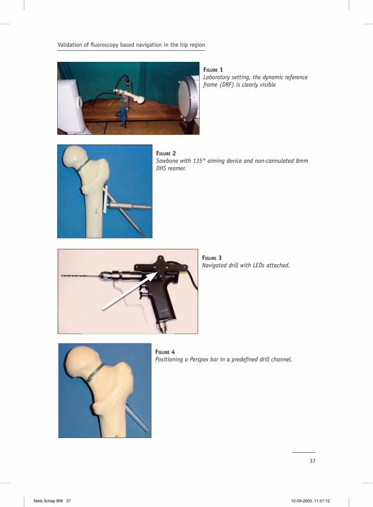
All tests were performed on 20 sawbones (Synbone AG Davos, Switserland) in a laboratory
setting.(Figure1) Drilling was performed directly with a specially developed non-canulated
8 mm DHS reamer, without the setup for plate reaming. A specially designed 135º aiming
device was used as a drill guide.(Figure 2) During drilling the virtual position of the DHS
reamer was superimposed on the AP and AX images of the proximal femur and was displayed
on the workstation ( Medivision, Oberdorf, CH.).
Niels Schep BW 35 12-09-2003, 11:57:06

36
Chapter 3
Position tracking was performed with light emitting diodes and an opto-elektric camera (
Optotrak 3020®, Nothern Digital –inc, Waterloo, Canada). The C-arm (Philips BV 300-9 inch,
Best, the Netherlands) was equipped with a shield holding 24 light emitting diodes (LEDs).
The C-arm images were calibrated to compensate for the elastic deformation caused by the
weight of the components of the C-arm under gravity and the fl uoroscope’s image intensifi er
distortion (5). To maintain the relationship between the sawbone and the fl uoroscopic images
a shield with four LEDs, named the dynamic reference frame (DRF) was rigidly attached to the
proximal part of the shaft of the sawbone before image acquisition. (Figure 1) LEDs were also
attached to a compact air drive to track its position. (Figure 3)
First, AP and AX images were made and loaded in the workstation. ‘ AX’ was defi ned as the
projection where the axis of the femoral neck was exactly in line with the axis of the shaft
of the femur. Subsequently, the C-arm was rotated 90 degrees and the projection defi ned as
‘AP’ was obtained.
Before drilling, a length calibration of the non-canulated 8 mm DHS reamer had to be
performed, the diameter of the reamer was also defi ned and stored in the system. During
drilling the starting point at the lateral femoral cortex and the end point at the preferred
position just below the femoral head cartilage were marked by pressing a footswitch. The
drill channel length measurements, provided by the navigation system, were compared with
true length measurements defi ned with a digital ruler (Helios, Niedernhall, Germany). This
procedure was repeated in all 20 sawbones.
To evaluate the virtual position of the navigated DHS reamer, new AP and AX images
were obtained with an 8 mm Perspex bar inserted in the predefi ned drill channel of each
sawbone.(Figure 4) The position of the Perspex bar in these fl uoroscopic images represented
the true position of the reamer and therefore, acted as a reference. These images were loaded
in the Medivision workstation. After image acquisition the Perspex bar was removed and
exchanged for the navigated DHS reamer. On the workstation the virtual position of the DHS
reamer was superimposed on the images containing the Perspex bar.
Next, the AP and AX images with and without the superimposed virtual reamer were
transferred to a personal computer (Pentium III, 600 Mhz, 256MB) for measurements. (Figure
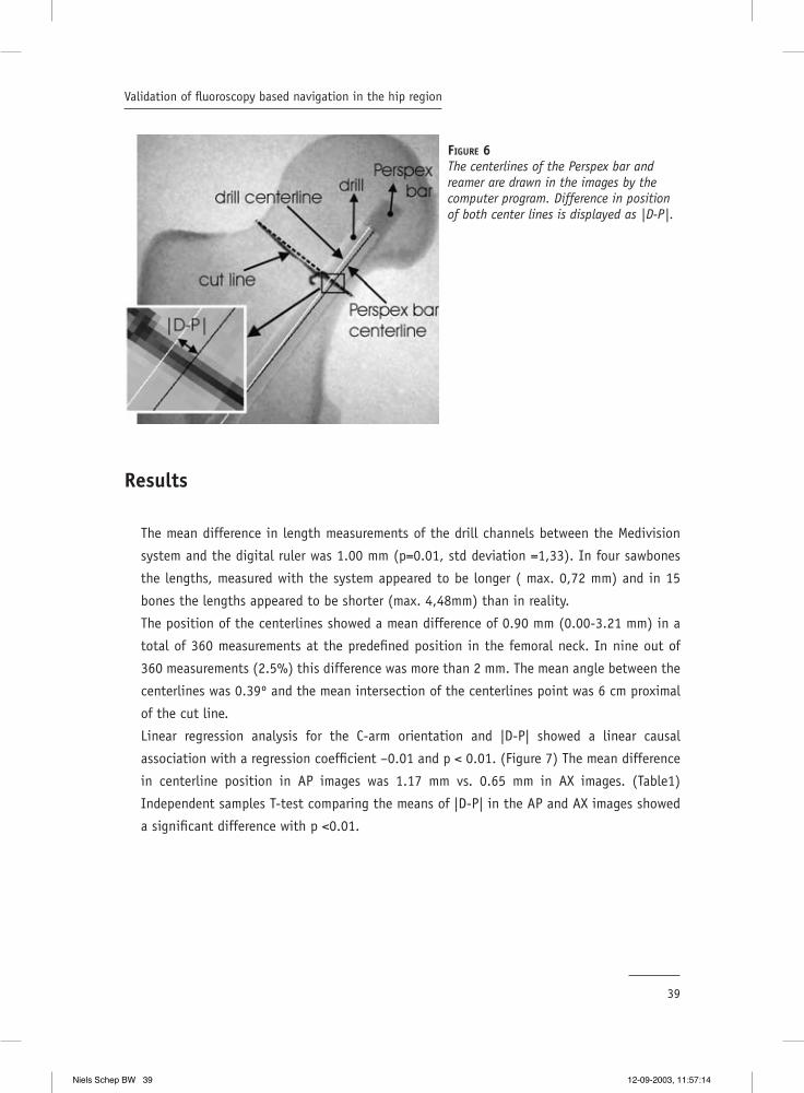
5) A dedicated computer program was developed to determine the centerlines and diameters
of both Perspex bar and virtual reamer. Differences between the centerline position of the
Perspex bar and the virtual reamer were determined in a standardized cut plane, outlined
by a radiographic marker placed centrally over the femoral neck. This difference in position
was defi ned as the positional error of the system in this test setup (|D-P|). (Figure 6)
Additionally, the angles between the centerlines were determined. Position measurements
Niels Schep BW 36 12-09-2003, 11:57:07
37
Validation of fl uoroscopy based navigation in the hip region
FIGURE 1Laboratory setting, the dynamic reference frame (DRF) is clearly visible
FIGURE 2Sawbone with 135° aiming device and non-cannulated 8mm DHS reamer.
FIGURE 4Positioning a Perspex bar in a predefi ned drill channel.
FIGURE 3Navigated drill with LEDs attached.
Niels Schep BW 37 12-09-2003, 11:57:12

38
Chapter 3
in AP en AX images were accomplished after fi ve different length calibrations, resulting in
200 measurements.
Intraoperatively it may be diffi cult to obtain accurate AP and AX images therefore the
infl uence of the C-arm orientation, during image acquisition, on the accuracy of the virtual
reamer position was also evaluated using the same methods. In every sawbone eight
additional fl uoroscopic images with the Perspex bar were obtained in angles of 90° (AX),
80°, 70°, 60°, 30°, 20°, 10° and 0° (AP). Again the difference in the centerline position
between the Perspex bar and the virtual reamer was assessed for each angle in 160 images.
Statistics
All results were evaluated with SPSS 7.5 for Windows (SPSS, Inc, Chicago, USA). First the
mean values of length measurements of the drill channels obtained with the navigation
system and the digital ruler were evaluated. With a Wilcoxon signed- rank test the hypothesis
was tested that no difference could be found between these populations.
The mean difference in position between the centerline position of the Perspex bar and
virtual reamer was calculated out of a total of 360 measurements. Additionally the mean
angle of the centerlines and the mean focal point was computed in all images.
To evaluate the relationship between the C-arm angles and the error of the system, a
scatterplot for X= C-arm angle and Y=|D-P| was drawn to evaluate the relationship between
the C-arm angles and the error of the system. Finally, a linear regression test was performed
for these variables.
FIGURE 5Captured AP images: Right image shows the Perspex bar, left image shows the navigated reamer, superimposed on the fl uoroscopic image. Black line on femoral neck is radiographic marker that has been used to determine the cutplane.
Niels Schep BW 38 12-09-2003, 11:57:14
39
Validation of fl uoroscopy based navigation in the hip region
Results
The mean difference in length measurements of the drill channels between the Medivision
system and the digital ruler was 1.00 mm (p=0.01, std deviation =1,33). In four sawbones
the lengths, measured with the system appeared to be longer ( max. 0,72 mm) and in 15
bones the lengths appeared to be shorter (max. 4,48mm) than in reality.
The position of the centerlines showed a mean difference of 0.90 mm (0.00-3.21 mm) in a
total of 360 measurements at the predefi ned position in the femoral neck. In nine out of
360 measurements (2.5%) this difference was more than 2 mm. The mean angle between the
centerlines was 0.39º and the mean intersection of the centerlines point was 6 cm proximal
of the cut line.
Linear regression analysis for the C-arm orientation and |D-P| showed a linear causal
association with a regression coeffi cient –0.01 and p < 0.01. (Figure 7) The mean difference
in centerline position in AP images was 1.17 mm vs. 0.65 mm in AX images. (Table1)
Independent samples T-test comparing the means of |D-P| in the AP and AX images showed
a signifi cant difference with p <0.01.
FIGURE 6The centerlines of the Perspex bar and reamer are drawn in the images by the computer program. Difference in position of both center lines is displayed as |D-P|.
Niels Schep BW 39 12-09-2003, 11:57:14

40
Chapter 3
TABLE 1
C-arm orientation N Mean D-P | (mm) Std.Deviation
Ap 20 1,17436641 0.5800024710° 20 1,20137107 0.7992429620° 20 1,17542793 0.6949612730° 20 1,25061356 0.5827841160° 20 1,07772820 0.5537331870° 20 0.79705981 0.5299968480° 20 0.56382671 0.37377910AX° 20 0.65380183 0.38322203
Discussion
The objective of this study was to evaluate the accuracy of the Medivision trauma module
for drilling the screw channel for a DHS. First the length measuring tool of the navigation
system was evaluated. In 75% of the cases virtual drill channel lengths measured with the
system were shorter (mean 1mm) than the true channel length. In practice this means that
in most cases undersized screws will be chosen. However, a mean difference of 1 mm is of no
clinical relevance for this procedure.
C-arm orientation in degrees
100806040200-20
| D-P
| (m
m)
3,5
3,0
2,5
2,0
1,5
1,0
,5
0,0
-,5
FIGURE 7Scatterplot: X= C-arm angle and Y=|D-P|
Niels Schep BW 40 12-09-2003, 11:57:18
41
Validation of fl uoroscopy based navigation in the hip region
In addition to length measurements, this study focussed on positional errors of the virtual
reamer, projected on single shot AP and AX images. In all experiments the difference in
position between the virtual reamer and true position was measured in a predefi ned cutplane
in the middle of the femoral neck We chose the clinically most relevant cutplane at the
narrowest point of the calcar. The position of the virtual reamer appeared to be reliable in
97% of cases when considering an inaccuracy of ≤ 2mm as clinically irrelevant. In nine out
of 360 measurements a difference of more than 2 mm was found. In these cases it is most
likely that the DRF was moved relative to the femur during the experiment, resulting in a loss
of the relationship between the sawbone and the fl uoroscopic images. This is an important
pitfall in surgical navigation. Intra-operatively the surgeon has to monitor the fi xation of the
DRF. In case loss of rigid fi xation is suspected it is obligatory to discontinue the procedure
and to acquire new images.
Obviously, the parameter |D-P| is dependent of the position of the cutplane chosen, in case
the centerline of the Perspex bar and the centerline of the virtual reamer do not run parallel.
However, the mean angle between these centerlines was 0.39º with the intersection point at
a mean distance of 6 cm ahead of the predefi ned measurement point. The inaccuracy, due to
the deviation of the centerlines from the intersection point at the level of the femoral head
will not lead to an unacceptable error.
Surprisingly, the accuracy of the virtual position of the reamer on 2-D fl uoroscopy images
appeared to be related to the angle of image acquisition. When the C-arm was moved from
AX (90°) to AP (0°), mean inaccuracy of the position of the virtual reamer increased..
Navigation based on AX fl uoroscopic images appeared to be more accurate compared to
navigation based on AP images. The C-arm images are calibrated to compensate for the
elastic deformation caused by the weight of the components of the C-arm under gravity and
the image intensifi er distortion. A possible explanation for the difference in error between
AP and AX images could be a difference in accuracy of C-arm calibration in the extreme
positions.
In conclusion, surgeons working with these systems have to realise that system inaccuracy
consists of the sum of multiple errors. Sources of these errors are inaccuracy in position
tracking by the opto-electric camera, in calibration of the C-arm, image distortion and in
calibration of the drilling tool. However, the fl uoroscopy based navigation system validated
in this study provides a reliable virtual position of the reamer compared with the true
situation when drilling the channel for a DHS.
Niels Schep BW 41 12-09-2003, 11:57:18
42
Chapter 3
Reference List
1. Alberts KA, Jervaeus J. Factors predisposing to healing complications after internal fi xation of femoral neck fracture. A stepwise logistic regression analysis. Clin Orthop 1990; 129-33.
2. Asnis SE, Wanek-Sgaglione L. Intracapsular fractures of the femoral neck. Results of cannulated screw fi xation. J Bone Joint Surg Am 1994; 76: 1793-803.
3. Brown JT, Abrami G. Transcervical femoral fracture. J Bone Joint Surg 1964; 46B: 648-63.
4. Suhm N. Computer assisted distal locking of intramedullary implants: a controlled clinical study including 84 patients. Computer Assisted Orthopaedic Surgery (CAOS), 1th annual meeting, Davos, Switzerland. 2001.
5. Hofstetter R, Slomczykowski M, Sati M, Nolte LP. Fluoroscopy as an imaging means for computer-assisted surgical navigation. Comput Aided Surg 1999; 4: 65-76.
6. Hofstetter R, Slomczykowski M, Krettek C, Koppen G, Sati M, Nolte LP. Computer-assisted fl uoroscopy-based reduction of femoral fractures and antetorsion correction. Comput Aided Surg 2000; 5: 311-25.
7. Slomczykowski MA, Hofstetter R, Sati M, Krettek C, Nolte LP. Novel computer-assisted fl uoroscopy system for intraoperative guidance: feasibility study for distal locking of femoral nails. J Orthop Trauma
Niels Schep BW 42 12-09-2003, 11:57:19
Validation of computer assisted anteversion and length control in closed nailing
of femoral shaft fractures
4Chapter
Submitted to Der Unfallchirurg ( in German)
N.W.L. Schep1, Th. van Walsum 2, M.H.J. Verhofstad1, E.J.M.Verleisdonk1
1 Department of Surgery2 Image Science institute
University Medical Centre Utrecht, The Netherlands
Niels Schep BW 43 12-09-2003, 11:57:19

Niels Schep BW 44 12-09-2003, 11:57:20
45
Validation of computer assisted anteversion and length control in closed nailing of femoral shaft fr
Summary
Objective: Computer Assisted Surgery (CAS) allows image guided femoral nailing and
intraoperative control of rotation and length. The goal of this study was to evaluate the
femoral anteversion angles and lengths provided by CAS in a cadaver study.
Material and Methods: Landmarks were manually defi ned in fl uoroscopic images displayed
on the CAS system to determine the anteversion and length of the femoral shaft. For
evaluation, a golden standard based on CT data was developed. The CAS length and rotation
values were compared with the CT-based ones. Inter-observer variability was assessed for
both methods.
Results: Differences in length measurement between the CAS and CT based method were <
1 cm. The variation in anteversion angles between the CAS and CT based method showed a
mean difference of 13º (max. 26º). CAS inter-investigator variability was 5.5º for anteversion
and 5.2 mm for length. For the CT-based method this was 3.1º for anteversion and 2.5 mm
for length measurement.
Conclusion: Length measurements by the navigation system showed to be reproducible and
accurate. The rotation measurements were reproducible with a mean difference of 5.5º but
not accurate enough to prevent malrotation.
Niels Schep BW 45 12-09-2003, 11:57:20

Niels Schep BW 46 12-09-2003, 11:57:20
47
Validation of computer assisted anteversion and length control in closed nailing of femoral shaft fr
Introduction
Locked intramedullary nailing is commonly used for the treatment of femoral shaft fractures.
For a limited invasive procedure the surgeon uses intraoperative fl uoroscopy for nail
insertion, fracture reduction and distal locking.
Drawback of this visualisation technique is the limitation to single two-dimensional (2-D)
fl uoroscopic projections. Repetitive position changes of the C-arm are required to obtain
both anteroposterior (AP) and axial (AX) images, resulting in substantial radiation exposure
to both patient and surgical team. (4;5) Moreover, this technique makes the procedure time
consuming and may jeopardize sterility.
An important complication of the conventional nailing procedure is malrotation of the
stabilised femur. Anteversion differences of 15° or more are found in 19 % and leg length
discrepancies of more than 10 mm in 9 % of the patients after operation. (1;2)
Recently, fl uoroscopy based surgical navigation was introduced into surgical practice. This
technique allows real time visualisation of surgical instruments superimposed into multiple
single-shot fl uoroscopic images. Hofstetter and others developed a computer-assisted
surgery (CAS) module for the surgical treatment of femoral shaft fractures.(3) This concept
allows image guided nail insertion, virtual alignment of bone fragments and intraoperative
assessment and control of rotation and length. Potential advantages of this technique
are reduction of radiation exposure, postoperative torsional deformities and leg length
discrepancies.
The goal of this study was to evaluate the femoral anteversion angles and lengths provided
by the navigation system (CAS) compared to a CT-based method (golden standard).
Material and Methods
Operative procedure
The experiments were performed in ten fresh cadaver legs. To allow fl uoroscopy based surgical
navigation, light emitting diodes (LED’s) were attached to a C-arm (Philips BV 300, Best, The
Netherlands) as well as to both femoral fracture fragments, the drilling machine and the nail
insertion handle. An optical tracking sensor (Optotrak 3020®, Northern Digital-inc, Waterloo,
Canada), overlooking the surgical fi eld, received the infrared light emitted by the LED’s
for position tracking. The LED’s attached to the fracture parts were referred to as dynamic
reference frames (DRF’s) to allow positional tracking of the fragments. (see fi gure 1).
Niels Schep BW 47 12-09-2003, 11:57:20

48
Chapter 4
Six fl uoroscopic images of the proximal, middle (fractured) and distal part of the femur in
an anteroposterior (AP) and lateral (AX) view were loaded into the navigation workstation
(Medivision Surgigate ®, Oberdorf, Switzerland). To determine the rotation and length of the
femoral shaft the following landmarks were manually defi ned in these images; the centre
of the femoral head, the femoral neck axis, the distal and proximal fragment axis and the
posterior and distal aspect of the condyles.
Based on these landmarks the anteversion angle (see fi gure 2) and the femoral length were
calculated by the navigation system. Two lines on the fl uoroscopic images represented the
axis of the proximal and distal fragments. The bone axis was optimally reduced when the two
lines were aligned in the AP and AX plane. (see fi gure 3).
First, the position of a 17 mm drillbit, equipped with LED’s was superimposed on the AP and
AX fl uoroscopic images of the proximal femur. With help of the navigation system the optimal
insertion point for an unreamed femoral nail (UFN, AO-Synthes®, Umkirch, Germany) in the
piriformis fossa was located and the cortex was opened.
Next, the nail was attached to the insertion handle (with LED’s). The tip and proximal part
of the nail were calibrated before insertion. During insertion the position of the nail tip and
the proximal part of the nail were superimposed on the fl uoroscopic images. Once the tip of
the nail reached the fracture region, the fracture was reduced with the navigation system by
aligning both virtual axes on the screen. Subsequently, the nail was passed into the distal
fragment. (see fi gure 4)
Distal locking was performed by loading an additional AX fl uoroscopic image, showing the
distal locking holes with a maximum diameter, as a perfect circle. To position the drill in the
locking hole a 4 mm drillbit was calibrated. Its virtual projection was superimposed in the
additional fl uoroscopic image, which enabled targeting. (see fi gure 5)
FIGURE 1A dynamic reference frame (DRF) was attached to the proximal and distal femoral fragment. This allowed position tracking of both fracture parts.
Niels Schep BW 48 12-09-2003, 11:57:21

49
Validation of computer assisted anteversion and length control in closed nailing of femoral shaft fr
FIGURE 2Defi nition of the femoral anteversion angle α. This is the angle between the femoral neck axis and the trans-condylar plane and can be calculated using the landmarks N1, N2, C1, C2, a1, a2. Femoral length was defi ned by the centre of the femoral head and the distal condyles
FIGURE 3Two virtual axis represent the proximal and distal medullar canal. The bone axis was optimally reduced when the two lines were aligned in the AP and AX plane.
Niels Schep BW 49 12-09-2003, 11:57:22
50
Chapter 4
Experiments and goals
To evaluate the anteversion and length values provided by the navigation system a golden
standard, based on CT data was developed by the Image Science Institute Utrecht.
For landmarking, a special purpose computer program was developed (www.imagexplorer.nl)
that allows navigation through coronal, sagittal and axial planes of CT data. A fourth
window showed an additional 3D reconstruction. In these four windows three investigators
defi ned the same landmarks as in the fl uoroscopic images. (see fi gure 6)
The landmarks defi ned the anteversion angles and lengths according to their defi nition by
Hofstetter. This made a comparison possible between the anteversion angles and lengths
determined by both methods.
Preoperative CT scans of all unfractured legs were acquired and stored in a database.
Subsequently, three investigators calculated the femoral length and anteversion for each
femur by 3D CT landmark defi nition. Additionally, the inter-investigator variance was
analysed.
Following attachment of both DRF’s in the unfractured femur, fl uoroscopic images of the
proximal and distal femur were obtained in AP and AX direction. The same three investigators
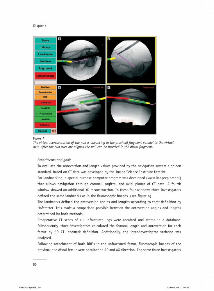
FIGURE 4The virtual representation of the nail is advancing in the proximal fragment parallel to the virtual axis. After the two axes are aligned the nail can be inserted in the distal fragment.
Niels Schep BW 50 12-09-2003, 11:57:26

51
Validation of computer assisted anteversion and length control in closed nailing of femoral shaft fr
defi ned the landmarks in these fl uoroscopic images. Consequently, three pair of anteversion
and length values were obtained for each unfractured femur. These values were compared
with the CT-based one’s. The inter-investigator variance was calculated for the computer-
assisted method as well.
Next, midshaft transverse femur fractures were created with an osteotomy. The fractures
were deliberately reduced with some rotation mistake to create variety in the postoperative
evaluation of rotation measurements. The quality of the CAS distal locking procedure was
scored as inadequate or adequate position of the drillbit. In all procedures the nails were
locked statically. The anteversion angles and lengths displayed by the navigation system
at the end of each procedure were recorded. Finally, CT scans of all stabilised femurs were
acquired and the three investigators computed the postoperative anteversion and length
using the CT based method. Additionally, these data were compared with the data provided
by the navigation system.
FIGURE 5Distal locking was performed by loading an additional AX fl uoroscopic image, showing the distal locking holes with a maximum diameter, as a perfect circle. The position of a calibrated 4 mm drill was projected in this image during the distal locking procedure.
Niels Schep BW 51 12-09-2003, 11:57:28

52
Chapter 4
Statistical analysis
The means of the three length and rotation values were calculated for each method in every
femur, pre- and postoperatively. Wilcoxon Signed rank tests were used to evaluate differences
in length and rotation between the CT based and fl uoroscopy based data.
Inter-investigator variance in length and rotation for both methods was evaluated in the
pre-operative data. The difference in rotation and length measurement between the three
investigators was calculated as the difference between the highest and lowest values.
A Wilcoxon Signed rank test was used to test whether there was a difference in inter-
investigator variance between the CT- and fl uoroscopy based data. P<0.05 was considered a
statistically signifi cant difference.
Results
Table 1 shows the comparison of the CAS based rotation and length values in relation to the
CT based values see table 1.
The mean difference between the investigators using the fl uoroscopy-based method was
5.5 º (1-11) for anteversion and 5.2 mm (2-10) for femoral length. The CT based method
showed a mean difference of 3.1 degrees (0.41-7.97) in anteversion and 2.5 mm (0.78-5.94)
in length. A signifi cant difference in inter-investigator variance between both methods was
FIGURE 6The same landmarks were identifi ed in a coronal, sagittal and axial plane CT image plane. Here the lateral posterior femoral condyle is identifi ed.
Niels Schep BW 52 12-09-2003, 11:57:30
53
Validation of computer assisted anteversion and length control in closed nailing of femoral shaft fr
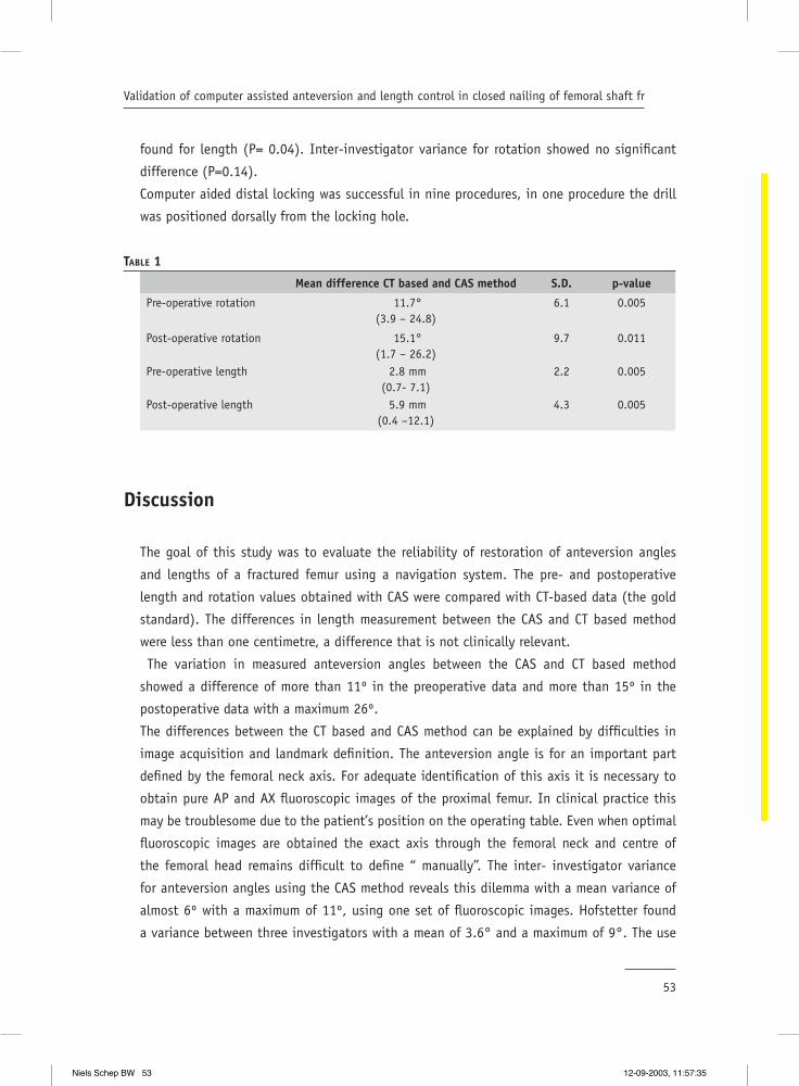
found for length (P= 0.04). Inter-investigator variance for rotation showed no signifi cant
difference (P=0.14).
Computer aided distal locking was successful in nine procedures, in one procedure the drill
was positioned dorsally from the locking hole.
TABLE 1
Mean difference CT based and CAS method S.D. p-value
Pre-operative rotation 11.7°(3.9 – 24.8)
6.1 0.005
Post-operative rotation 15.1°(1.7 – 26.2)
9.7 0.011
Pre-operative length 2.8 mm(0.7- 7.1)
2.2 0.005
Post-operative length 5.9 mm(0.4 –12.1)
4.3 0.005
Discussion
The goal of this study was to evaluate the reliability of restoration of anteversion angles
and lengths of a fractured femur using a navigation system. The pre- and postoperative
length and rotation values obtained with CAS were compared with CT-based data (the gold
standard). The differences in length measurement between the CAS and CT based method
were less than one centimetre, a difference that is not clinically relevant.
The variation in measured anteversion angles between the CAS and CT based method
showed a difference of more than 11º in the preoperative data and more than 15º in the
postoperative data with a maximum 26º.
The differences between the CT based and CAS method can be explained by diffi culties in
image acquisition and landmark defi nition. The anteversion angle is for an important part
defi ned by the femoral neck axis. For adequate identifi cation of this axis it is necessary to
obtain pure AP and AX fl uoroscopic images of the proximal femur. In clinical practice this
may be troublesome due to the patient’s position on the operating table. Even when optimal
fl uoroscopic images are obtained the exact axis through the femoral neck and centre of
the femoral head remains diffi cult to defi ne “ manually”. The inter- investigator variance
for anteversion angles using the CAS method reveals this dilemma with a mean variance of
almost 6º with a maximum of 11º, using one set of fl uoroscopic images. Hofstetter found
a variance between three investigators with a mean of 3.6° and a maximum of 9°. The use
Niels Schep BW 53 12-09-2003, 11:57:35

54
Chapter 4
of fresh cadavers and consequently a less fl uoroscopic image quality may be responsible for
our worse outcome.
Applying the CT-based method the femoral neck axis is defi ned in three different image
planes, which makes identifi cation more straightforward and accurate. This argument
supported our theory that the CT-based method is to be accepted as the gold standard.
However, a signifi cant difference in inter-investigator anteversion variance between the CT
and CAS method could not be determined. This is probably due to the limited number of
data. For variance in lengths the difference was signifi cant.
Navigated distal locking was successful in nine out of ten procedures. The inadequate
positioning of the drill in one procedure was most probably caused by a non-rigid fi xation
of the distal DRF.
Up till now this is the only study in which the CAS procedure for the nail insertion is
performed in cadavers instead of sawbones. Therefore, we would like to comment on the
clinical procedure. In a previous study it was showed that the projection of the drill in the
fl uoroscopic images is accurate with a mean deviation of 0.9 mm.(6) Consequently, in this
experiment it was possible to position the drill in the pirifi rmis fossa accurately.
Once the calibrated nail was inserted and had reached the fracture region the surgeon had to
align the proximal and distal fragment and advance the nail with the help of the navigation
system. When the fragments were moved, the axis of the distal fragment was moving out the
X-ray representation. In practice it appeared to be diffi cult to target the tip of the nail on
the predefi ned virtual distal axis due to its relative small diameter. To smooth the progress
of this procedure it will help the surgeon to see the actual fracture fragments move, instead
of the virtual axis.
Conclusionsthe length measurements provided by the navigation system showed to be reproducible
and accurate enough for clinical use. The rotation measurements were reproducible with a
difference of almost six degrees but not accurate enough to prevent malrotation considering
the CT based method as the gold standard. When using the anteversion angle of the
contralateral (unbroken) extremity as a template for the reduction the inter investigator
variance may be enough to avoid outliers. This will be the subject for further research.
Niels Schep BW 54 12-09-2003, 11:57:36

55
Validation of computer assisted anteversion and length control in closed nailing of femoral shaft fr
Reference List
1. Braten, M., Terjesen, T., and Rossvoll, I.: Torsional deformity after intramedullary nailing of femoral shaft fractures. Measurement of anteversion angles in 110 patients. J. Bone Joint Surg. Br. 75:799-803, 1993.
2. Braten, M., Terjesen, T., and Rossvoll, I.: Femoral shaft fractures treated by intramedullary nailing. A follow-up study focusing on problems related to the method. Injury. 26:379-383, 1995.
3. Hofstetter, R., Slomczykowski, M., Krettek, C., Koppen, G., Sati, M., and Nolte, L. P.: Computer-assisted fl uoroscopy-based reduction of femoral fractures and antetorsion correction. Comput. Aided Surg. 5:311-325, 2000.
4. Madan, S. and Blakeway, C.: Radiation exposure to surgeon and patient in intramedullary nailing of the lower limb. Injury. 33:723, 2002.
5. Mehlman, C. T. and DiPasquale, T. G.: Radiation exposure to the orthopaedic surgical team during fl uoroscopy: “how far away is far enough?”. J. Orthop Trauma. 11:392-398, 1997.
6. Schep, N. W. L., van Walsum, TH., de Graaf, J. S., Broeders, I. A. M. J., and van der Werken, Chr. Validation of fl uoroscopy based navigation in the hip region. HU Lemke et al. CARS 2002. Amsterdam, Elsevier sciences. 26-6-2002.
Niels Schep BW 55 12-09-2003, 11:57:37

Niels Schep BW 56 12-09-2003, 11:57:38
Virtual planning of anterior cruciate ligament insertion.
“Validation of a new technique”
5Chapter
Submitted to Arthroscopy
N.W.L. Schep1; M.H.J. Stavenuiter2, C.H. Diekerhof2, E.P.Martens3, M.van Haeff2, I.A.M.J.Broeders1, D.B.F. Saris2
1 Department of Surgery,2 Department of Orthopaedic Surgery
3 Centre for Bio statistics, University Utrecht
University Medical Centre Utrecht, The Netherlands
Niels Schep BW 57 12-09-2003, 11:57:38

Niels Schep BW 58 12-09-2003, 11:57:39

59
Virtual planning of anterior cruciate ligament insertion
Summary
Objective: To evaluate surgical variance in positioning an anterior cruciate ligament graft
using computer aided technique. Secondary, computer aided planning was compared with a
conventional procedure in the same knee.
Materials and Methods: The study was performed in 12 cadaver knees. Three surgeons with a
different experience level participated. Computer aided ACL planning was compared between
two surgeons in the same cadaver knee. The computer system outlined an impingement area
and visualised graft elongation in a virtual manner. Both surgeons positioned the virtual
graft in such a way that impingement was avoided and graft elongation was < 4mm during
fl exion and extension. The hypothesis of no difference between both planning procedures
was tested. A third surgeon performed a conventional procedure on the same cadaver knee.
The position and kinematics of this graft were also analysed with the computer system.
Additionally, the hypothesis was tested that the difference between the two planning
procedures was dissimilar to the mean difference between the both planning procedures and
the conventional procedure.
Results: The difference in planning was 5.02 mm (Std 2.40, 1.77-9.64) for the tibial and
4.61 mm (Std 2.13, 2.06-8.42) for the femoral tunnel. The mean difference between the
planned and conventional procedures was 6.20 mm (Std 2.49, 3.00-10.39) in the femur and
6.46 mm (Std.2.27. 2.65-10.47) in the tibia. No signifi cant differences were observed when
the mean distance between the two planning procedures was evaluated in relation to the
mean distance between the both planning procedures and the conventional procedure. The
two less experienced surgeons were responsible for three impingement cases performing a
conventional procedure.
Conclusion: Computer aided planning may reduce inter-surgical variance. Less experienced
surgeons and residents can benefi t from the system to reduce the number of malpositioned
tunnels.
Niels Schep BW 59 12-09-2003, 11:57:39

Niels Schep BW 60 12-09-2003, 11:57:41

61
Virtual planning of anterior cruciate ligament insertion
Introduction
Endoscopic reconstruction of a torn anterior cruciate ligament (ACL) with a patellar tendon
graft is a commonly performed procedure. In the United States more than 50.000 knees
are reconstructed each year.(6) The most critical step in this procedure is placement of the
femoral and tibial tunnels, in which the graft is secured. An accurate position of these tunnels
can minimise stretching of the graft and decreases the risk of impingement against the roof
of the notch during extension of the knee.(1;4-7) The consequences of graft over stretching
include graft tightening, graft slackening and graft failure. Whereas, impingement may lead to
persistent effusion, failure to regain full extension and eventually graft failure. (10)
To improve the accuracy and reproducibility of graft placement, intraoperative virtual reality
was added to traditional ACL reconstruction technique. Desenne et al. introduced a computer
system to predict notch impingement and graft elongation. (3) With this technique a virtual
knee was reconstructed and displayed on a computer screen. Intra-operatively, the surgeon
defi ned the femoral and tibial attachment sides of the graft. Next, the computer created
a virtual ACL between these points. During fl exion and extension of the knee the surgeon
was able to monitor impingement and elongation of the graft. (9) Theoretically, this way
of virtual planning should diminish the variance between surgeons and may lead to a more
accurate and reproducible procedure. Sati et al. described an experiment with six surgeons
positioning an ACL in one cadaver knee with this computer aided technique. This study
described a tight graphical clustering of the six planned ligament positions, demonstrating
a small variance in positioning both tunnels.(9)
The aim of our study was to test this hypothesis in a larger study and to illustrate surgical
variance in mm. Therefore, the virtual planning for insertion points in the tibia and femur
was compared between surgeons. Secondary, the computer aided virtual planning was
compared with the insertion points of a conventional procedure in the same knee.
Materials and Methods
The study was performed in 12 fresh cadaver knees. After introduction of the endoscope
(Arthrex, Napels, Florida, USA) the ACL and its footprint were removed with a shaver
(Dyonics PS3500EP, Smith & Nephew Inc, Andover, Ma). Position tracking of the femur,
tibia and palpation hook was performed by an opto-electric navigation system. Therefore,
both long bones and the palpation hook were equipped with a rigid shield holding light
emitting diodes (LED’s). The LED’s on femur and tibia were called the dynamic reference
Niels Schep BW 61 12-09-2003, 11:57:41
62
Chapter 5
frames (DRF’s). An opto-electric camera (Optotrak 3020, Nothern Digital, Waterloo, Canada),
overlooking the surgical fi eld, received the signals emitted by the LED’s. (Figure 1) This
allowed the workstation (Medivision, Oberdorf, Switzerland) to calculate the relative motion
between the femur, tibia and palpation hook.
At the start of each procedure the point of the palpation hook was calibrated to defi ne the
coordinates of its tip and axis in relation to its LED shield. Next, a set of landmarks was
collected with this palpation hook. Therefore, the surgeon placed the tip of the palpation
hook on a certain anatomical point and pressed a footswitch. The anterior side of the notch
was defi ned by digitising a collection of surface points under endoscopic control. These
points defi ned the area of impingement with the planned ACL graft. Finally, the preferred
attachment points of the ACL in femur and tibia were digitised which enabled the system to
draw a virtual knee with its proposed ligament reconstruction.
Impingement was visualised by the graphical intersection of the virtually planned ligament
with the digitised anterior notch surface during extension of the knee. In another window
the elongation of the graft in mm was shown during a range of motion of 90º fl exion and
complete extension.(Figure 2)
Three surgeons participated in the project. Surgeon A had performed more than 300 ACL
reconstruction procedures. Surgeon B just fi nished his residency and had experience in
twenty cases and surgeon C had no surgical experiences in this area.
First, the virtual planning of the tibial and femoral ACL insertion was compared between two
surgeons in the same cadaver knee. Both surgeons were blinded for each other’s planning.
Each surgeon performed eight planning and four conventional procedures in the 12 different
knees. During computer aided planning the goal was to defi ne the position of the tibial and
femoral tunnel in such a way that impingement with the anterior notch was avoided during
extension. Graft elongation had to be less than four mm during the whole range of motion.
The diameter of the simulated graft was set to eight mm in all cases.
The position of both tunnels was defi ned by the centre of the cylinder representing the
virtual ACL and was provided by the computer system in XYZ coordinates. The femoral tunnel
coordinates were calculated using the femoral DRF as a reference, whereas the tibial tunnel
coordinates referred to the tibial DRF. The variance in planning between two surgeons was
calculated by subtraction of XYZ coordinates to determine point to point discrepancy in
3D orientation. This distance represented the variance between surgeons in planning the
femoral and tibial tunnels. Additionally, the relationship between the difference in planning
and the experience level of the surgeons was evaluated.
Niels Schep BW 62 12-09-2003, 11:57:42

63
Virtual planning of anterior cruciate ligament insertion
FIGURE 1Shields with Light Emitting Diodes (LED’s) were attached to the tibia, femur and palpation hook for position tracking. The opto-electric camera received these signals and sent them to the workstation
FIGURE 2Impingement was visualised by the graphical intersection of the virtually planned ligament with the digitised anterior notch surface during extension of the knee. In another window the elongation of the graft in mm was shown during a range of motion of 90º fl exion and complete extension
Niels Schep BW 63 12-09-2003, 11:57:43
64
Chapter 5
A third surgeon performed a conventional procedure on the same cadaver knee. All surgeons
performed a total of four conventional procedures. A tibial aiming device (Arthrex, Napels,
Florida, USA) was used to drill the tibial tunnel with a guide wire. Drilling was stopped just
when the cortex of the tibia plateau was penetrated. The tip of the guide wire resembled the
centre of the tibial tunnel and was digitised to obtain its coordinates. Next, a fi ve mm over
the top femoral aiming guide (Arthrex, Napels, Florida, USA) was used to drill the femoral
guide wire. The point at which the guide wire entered the femoral cortex was subsequently
digitised and its coordinates were stored. During the complete procedure an arthroscopy
pump (Duo+, Future Medical Systems, Nice, France) was used to remove debris.
Once more a virtual ACL with an eight millimetre diameter was drawn by the workstation,
representing positioning of the ACL graft using the conventional technique. The incidence
of notch impingement and the elongation were scored during fl exion and extension of the
knee. Finally, the difference in tunnel position between the two virtual planning procedures
and the conventional procedure was calculated.
Statistics
First, the mean difference in mm between both virtual planning procedures for the femoral
and tibial tunnels was calculated. The hypothesis of no difference in distance between
both planning procedures was tested with a paired T-test. A Kruskal-Wallis test was used to
analyse if the differences in planning were related to the experience level of the surgeons.
Next, the mean difference in tunnel position between the conventional procedure and the
both planned procedures was calculated. Figure 3 Additionally, the hypothesis was tested
that the difference between the two planning procedures (∆plan) was dissimilar to the mean
difference between the both planning procedures and the conventional procedure ( (∆plan
1-Co + ∆plan 2-Co)/ 2 ). A paired sample T-test was used to test this hypothesis for the
femoral and tibial insertion points.
In a total of 12 conventional procedures the median elongation and impingement ratio was
scored. An oneway Anova was used to evaluate the relationship between the experience level
of the surgeon, performing the conventional procedure and the difference between planning
and the conventional procedure.
Niels Schep BW 64 12-09-2003, 11:57:49

P2
P1
P3
plan
Plan 1- C0
Plan 2- C0
65
Virtual planning of anterior cruciate ligament insertion
Results
The positioning of the virtual tibial tunnels showed a mean difference in planning of 5.02
mm (Std 2.40, 1.77-9.64). The mean difference between the virtual planning for the femoral
tunnels was 4.61 mm (Std 2.13, 2.06-8.42). The difference in distance between the tibial
and femoral planning was not signifi cant with p= 0.75. Additionally, the experience level did
not infl uence the difference in virtual planning between the three surgeons with p= 0.08 for
the femoral and p=0.52 for the tibial tunnel.
The mean difference between the planned and conventional procedures in the femur was
6.20 mm (Std 2.49, 3.00-10.39). In the tibia a mean difference of 6.46 mm (Std.2.27. 2.65-
10.47) was found. No signifi cant differences were observed when the mean distance between
the two planning procedures was evaluated in relation to the mean distance between the
both planning procedures and the conventional procedure. Table 1
TABLE 1
Paired Sample T-test Mean Std. Deviation Sig.
Pair 1 ∆plan 1-Co + ∆plan 2-Co (Femur) ∆ plan (Femur)
6.204.61
2.492.13
0.33
Pair 2 ∆plan 1-Co + ∆plan 2-Co (Tibia) ∆ plan (Tibia)
6.465.02
2.272.40
0.85
No signifi cant differences were observed when the mean distance between the two planning
procedures was evaluated in relation to the mean distance between the both planning
procedures and the conventional procedure.
FIGURE 3P1 = planning 1P2 = planning 2CO= conventional procedures
In both femur and tibia two virtual planning procedures and one conventional procedure were performed.
Niels Schep BW 65 12-09-2003, 11:57:50
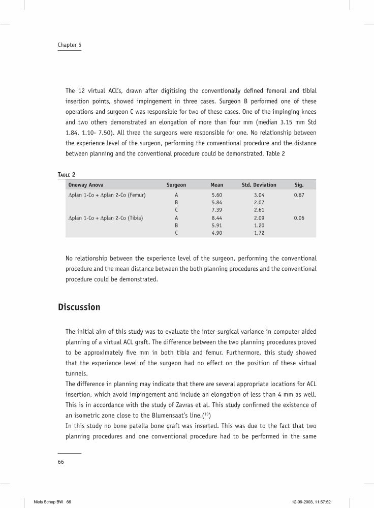
66
Chapter 5
The 12 virtual ACL’s, drawn after digitising the conventionally defi ned femoral and tibial
insertion points, showed impingement in three cases. Surgeon B performed one of these
operations and surgeon C was responsible for two of these cases. One of the impinging knees
and two others demonstrated an elongation of more than four mm (median 3.15 mm Std
1.84, 1.10- 7.50). All three the surgeons were responsible for one. No relationship between
the experience level of the surgeon, performing the conventional procedure and the distance
between planning and the conventional procedure could be demonstrated. Table 2
TABLE 2
Oneway Anova Surgeon Mean Std. Deviation Sig.
∆plan 1-Co + ∆plan 2-Co (Femur) ABC
5.605.847.39
3.042.072.61
0.67
∆plan 1-Co + ∆plan 2-Co (Tibia) ABC
8.445.914.90
2.091.201.72
0.06
No relationship between the experience level of the surgeon, performing the conventional
procedure and the mean distance between the both planning procedures and the conventional
procedure could be demonstrated.
Discussion
The initial aim of this study was to evaluate the inter-surgical variance in computer aided
planning of a virtual ACL graft. The difference between the two planning procedures proved
to be approximately fi ve mm in both tibia and femur. Furthermore, this study showed
that the experience level of the surgeon had no effect on the position of these virtual
tunnels.
The difference in planning may indicate that there are several appropriate locations for ACL
insertion, which avoid impingement and include an elongation of less than 4 mm as well.
This is in accordance with the study of Zavras et al. This study confi rmed the existence of
an isometric zone close to the Blumensaat’s line.(10)
In this study no bone patella bone graft was inserted. This was due to the fact that two
planning procedures and one conventional procedure had to be performed in the same
Niels Schep BW 66 12-09-2003, 11:57:52

67
Virtual planning of anterior cruciate ligament insertion
cadaver knee. Consequently, no validation of graft kinematics could be executed. Therefore,
the values of the computer were defi ned as the standard in all tests.
Secondary, computer aided virtual planning was compared with the tunnel position of a
conventional procedure. The mean distance between the planned and the conventional
procedures proved to be more than six mm for both the tibia as the femoral tunnel. No
signifi cant difference with the distance between the two planned procedures could be
observed. However, there is a trend showing that the positions of both planning procedures
are more close related. The mean of ∆P shows to be smaller compared with the mean
distance to conventional positioning in both femur and tibia, which resembles a decrease
in the margin of error.
The virtual graft, drawn after the conventional procedure, showed impingement in three
out of twelve knees and an elongation of more than four mm in two additional knees. The
less experienced surgeon was responsible for two of these impingement cases. The three
knees with an elongation of more than four mm were equally distributed among the three
surgeons. These data connect with the hypothesis that less experienced surgeons will have
a higher impingement rate compared with experienced surgeons.
The meaning of intra-operative isometry measurement is still controversial. Some authors
recommend an isometric area for ACL placement others claim that isometry has little
effect on the clinical outcome. (2;6;10) The European Society of Sports traumatology Knee
surgery and Arthroscopy recommended in their second workshop “a good choice of graft
attachment points will result in minimal changes in their separation distance as the knee
fl exes and extends”.(1) It is important to realise that even if a perfect isometric point could
be located and the bone tunnels are positioned around this point a reconstruction with a
bone patella bone graft is not isometric due to the acentric insertion of the graft on the
bone blocks. Tendon grafts, however, do have a central placement within the tunnels. This
may help to improve clinical outcome based on isometric parameters.
No signifi cant relationship between the experience level of the surgeon, performing
the conventional procedure and the distance to the planning was observed. However,
the most experienced surgeon proved to locate the femoral tunnel the nearest to the
planned position. Surprisingly, this same surgeon positioned the tibial tunnel with the
largest discrepancy compared to the plan. However, in all these cases no impingement
was observed and in one case elongation was > 4mm (7.5 mm). Literature shows that the
femoral attachment side has a greater effect on graft length changes than does the tibial
attachment.(1) This may be an explanation for the discrepancy in the relation between
experience and tibial position.
Niels Schep BW 67 12-09-2003, 11:57:53

68
Chapter 5
In conclusion this study indicates that computer aided planning may reduce the inter-
surgical variance. Moreover, the experience level of the surgeon did not effect the planning
process. Secondary, less experienced surgeons and residents can benefi t from the system to
reduce the number of malpositioned tunnels. The literature teaches us that the incidence
of misplaced tunnels may be as high as 40%. (8) Randomised trials must be performed in
the future to judge whether the computer-aided technique may lower this fi gure and offers
the patients a better clinical outcome.(9)
Niels Schep BW 68 12-09-2003, 11:57:55

69
Virtual planning of anterior cruciate ligament insertion
Reference List
1. Amis, A. A. and Jakob, R. P.: Anterior cruciate ligament graft positioning, tensioning and twisting. Knee. Surg. Sports Traumatol. Arthrosc. 6 Suppl 1:S2-12, 1998.
2. Barrett, G. R. and Treacy, S. H.: The effect of intraoperative isometric measurement on the outcome of anterior cruciate ligament reconstruction: a clinical analysis. Arthroscopy. 12:645-651, 1996.
3. Dessenne, V., Lavallee, S., Julliard, R., Orti, R., Martelli, S., and Cinquin, P.: Computer-assisted knee anterior cruciate ligament reconstruction: fi rst clinical tests. J. Image Guid. Surg. 1:59-64, 1995.
4. Fineberg, M. S., Zarins, B., and Sherman, O. H.: Practical considerations in anterior cruciate ligament replacement surgery. Arthroscopy. 16:715-724, 2000.
5. Fineberg, M. S., Zarins, B., and Sherman, O. H.: Practical considerations in anterior cruciate ligament replacement surgery. Arthroscopy. 16:715-724, 2000.
6. Frank, C. B. and Jackson, D. W.: The science of reconstruction of the anterior cruciate ligament. J. Bone Joint Surg. Am. 79:1556-1576, 1997.
7. Frank, C. B. and Jackson, D. W.: The science of reconstruction of the anterior cruciate ligament. J. Bone Joint Surg. Am. 79:1556-1576, 1997.
8. Picard, F., DiGioia, A. M., Moody, J., Martinek, V., Fu, F. H., Rytel, M., Nikou, C., LaBarca, R. S., and Jaramaz, B.: Accuracy in tunnel placement for ACL reconstruction. Comparison of traditional arthroscopic and computer-assisted navigation techniques. Comput. Aided Surg. 6:279-289, 2001.
9. sati, M., Staubli, H. U., Bourquin, Y., Kunz, M., and Nolte, L. P.: Real-time computerized in situ guidance system for acl graft placement. Comput. Aided Surg. 7:25-40, 2002.
10. Zavras, T. D., Race, A., Bull, A. M., and Amis, A. A.: A comparative study of ‘isometric’ points for anterior cruciate ligament graft attachment. Knee. Surg. Sports Traumatol. Arthrosc. 9:28-33, 2001.
Niels Schep BW 69 12-09-2003, 11:57:55

Niels Schep BW 70 12-09-2003, 11:57:56

Internal fi xation of femoral neck fractures with computer assisted surgery.
“A report on fi rst cases”
6Chapter
European Journal of Trauma in press
N.W.L. Schep, E.J.M. Verleisdonk, I.A.M.J. Broeders, F.M. Kappelhoff and Chr. van der Werken.
Department of Surgery
University Medical Centre Utrecht, The Netherlands
Niels Schep BW 71 12-09-2003, 11:57:57

Niels Schep BW 72 12-09-2003, 11:57:57

73
Internal fi xation of femoral neck fractures with computer assisted surgery
Summary
Objective: In standard practice, osteosynthesis of femoral fractures is guided interactively
by 2D fl uoroscopy providing anteroposterior (AP) or axial (AX) projections. This approach
leads to repetitive position changes of the C-arm with concomitant radiation exposure and
may result in sub-optimal positioning of implants. Fluoroscopy based navigation may offer
a solution for these problems. The goal of this study was to evaluate the feasibility of
fl uoroscopy based navigation in the treatment of intracapsular femoral neck fractures with
a dynamic hip screw (DHS).
Patients and Methods: Seven patients were treated with a 135° DHS. Fluoroscopy based
navigation technique (Medivision, Oberdorf, Switzerland) was used for positioning the
correct drill channel for the DHS. Therefore, the virtual position of an 8-mm non-cannulated
DHS reamer was superimposed simultaneously on the AP and AX images.
Results: One procedure failed because the position of the virtual drill did not match the true
situation. In this case it was most likely that the DRF was moved relative to the proximal
femur during the operation. This operation was continued under fl uoroscopic guidance. In
one patient the DHS was located in the cortex of the femoral head. In another patient the
DHS was positioned not exactly in the centre of the femoral neck but slightly posterior. Mean
system set-up time was 10 min.
Conclusion: Fluoroscopy based navigation is a feasible technique for the treatment of femoral
neck fractures with a DHS. The initial results are encouraging. More intuitive techniques are
currently developed to enhance implication of navigation in routine trauma care.
Niels Schep BW 73 12-09-2003, 11:57:58

Niels Schep BW 74 12-09-2003, 11:57:58
75
Internal fi xation of femoral neck fractures with computer assisted surgery
Introduction
The dynamic hip screw (DHS, AO-Synthes®) is a popular implant for the stabilisation of
femoral neck fractures. An essential part of the operation is the insertion of a guide wire over
the calcar into the femoral head under fl uoroscopic guidance.
Drawback of this technique is the intraoperative visualisation, because positional information
of the K-wire is limited to single two-dimensional (2-D) fl uoroscopic projections. This leads
to repetitive position changes of the C-arm because both anteroposterior (AP) and axial (AX)
images are required and makes the procedure prone to imperfect positioning of the implant.
Moreover, interactive fl uoroscopic guidance results in a substantial radiation exposure to
both patients and surgical team. (3;4)
Fluoroscopy based navigation may offer a solution to these problems. With this technique
the virtual position and direction of a drillbit is simultaneously superimposed on standard AP
and AX fl uoroscopic images. (1;2;6) Consequently, the channel for the hip screw can be drilled
under constant virtual guidance, without the use of a K-wire.
Potential advantages of computer assisted surgery (CAS) in femoral neck fractures are a more
accurate and reproducible approach for inserting a DHS-screw and a reduction of fl uoroscopy
time. These advantages may possibly result in a better patient’s outcome and reduction of
operation time. In order to test the feasibility and accuracy of drilling and measuring the screw
channel of a DHS an experimental study in 20 sawbones was performed. (5) The results of this
study were encouraging and led to clinical implementation of this technique.
Consequently, the aim of this clinical study was to evaluate the feasibility and pitfalls of
CAS in the treatment of femoral neck fractures with a DHS.
Patients and Methods
In the operating theatre a tracking sensor was installed (opto-electric camera, Optotrak
3020®, Northern Digital-inc, Waterloo, Canada) This tracking sensor received signals emitted
by infrared emitting diodes (LED’s). These LED’s were attached to the drill and to the patient.
The LED’s attached to the patient are called the dynamic reference frame (DRF). (Figure 1)
Likewise, the C-arm (Philips BV 300, Best, The Netherlands) was equipped with a shield
holding 24 LED’s. This allowed position tracking of the C-arm in a wide range of motions
relative to the opto-electric camera. C-arm images were calibrated to compensate for the
elastic deformation caused by the weight of the components of the C-arm under gravity and
for the fl uoroscope’s image intensifi er distortions.(2)
Niels Schep BW 75 12-09-2003, 11:57:59
76
Chapter 6
All patients were operated in supine position on a fracture table. After closed reduction of
the fracture the injured leg was brought in traction. In four patients the DRF was attached
rigidly with a Steinmann pin in the iliac crest and in three patients in the greater trochanter.
Subsequently, AP and AX fl uoroscopic images were obtained and loaded into the workstation
(Medivision Surgigate ®, Oberdorf, Switzerland). The AX plane was defi ned as the projection
where the neck axis was exactly in line with the axis of the shaft. Next, the C-arm was
rotated exactly 90º. This projection defi ned the AP plane.
The proximal femur was exposed by means of a 4 cm straight lateral incision on the thigh.
A temporary fi xation of the reduced fragments was obtained with a K-wire proximal of the
implant site of the hip screw. After merging the positional information of the patient, drillbit
and C-arm, the virtual position and direction of the drillbit was superimposed on the AP and
AX fl uoroscopic images and displayed on the workstation. (Figure 2)
The surgeon instantaneously drilled the hole for the hip screw under constant virtual
guidance. The virtual drill was targeted straight over the calcar in AP projection and in the
center of the femoral neck in AX projection. Defi ning the depth of the drill channel was based
on the surgeon’s judgement on bone quality.
Two adjustments were made to standard instruments. First, a procedure dedicated aiming
device was designed, based on the standard 135º aiming device, with
an 8 mm channel for the DHS drill.( Figure 3) This enabled the surgeon to drill the channel
for the DHS directly in the correct position. Secondly, the standard cannulated 8 mm DHS
reamer was made non-cannulated by fi xating a K-wire in the central hole, which exceeded the
tip of the drillbit by two mm. The tip of this K-wire was pressed in the lateral femoral cortex
just before drilling, establishing better grip on the lateral femoral cortex.
During drilling the starting point at the lateral femoral cortex and the end point at the
preferred position just below the joint space were marked by pressing a footswitch. The drill
channel depth was computed by the system and displayed on the monitor. Subsequently,
the plate reamer was attached to the 8 mm DHS reamer at the appropriate depth and the
plate hole was drilled. Next, the hip screw, a 135° plate and one 4.5 mm cortical screw were
inserted by standard technique. (Figure 4)
Niels Schep BW 76 12-09-2003, 11:58:00
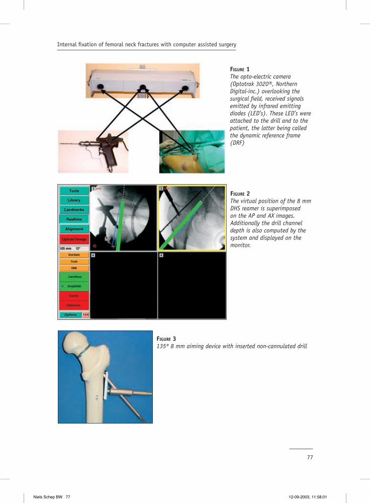
77
Internal fi xation of femoral neck fractures with computer assisted surgery
FIGURE 1The opto-electric camera (Optotrak 3020®, Northern Digital-inc.) overlooking the surgical fi eld, received signals emitted by infrared emitting diodes (LED’s). These LED’s were attached to the drill and to the patient, the latter being called the dynamic reference frame (DRF)
FIGURE 2The virtual position of the 8 mm DHS reamer is superimposed on the AP and AX images. Additionally the drill channel depth is also computed by the system and displayed on the monitor.
FIGURE 3135º 8 mm aiming device with inserted non-cannulated drill
Niels Schep BW 77 12-09-2003, 11:58:01

78
Chapter 6
Preoperatively, basic demographic data, including Garden fracture classifi cation were
recorded. Intraoperatively, procedure time, operating time and radiation exposure were
scored. The C-arm provided the total radiation dose and fl uoroscopy time after each procedure.
These values were considered representative for the radiation exposure. Postoperatively, the
position of the DHS was evaluated on control X-rays.
Results
Seven consecutive patients (6 females, one male) with a femoral neck fracture underwent
osteosynthesis with a DHS. Their ages ranged from 53 to 85 years (median, 76 years).
Fracture classifi cation according to Garden showed two grade one, one grade two, two grade
three, and two grade four fractures.
The median operation time, measured from skin incision to closure, was 44 minutes (range
30-75). The median procedure time, including system set-up time, closed reduction,
uploading images in the workstation and extubation of the patient was 120 minutes (range
110-145). For comparison the median procedure time in a series of 42 patients treated with a
DHS in our hospital was retrospectively subtracted from patients fi les. The median procedure
time in this conventionally treated group was 108 minutes (range 60-210). An experienced
MD performed the set-up of the system in all cases with a median of 10 minutes (range 8-
15). Fluoroscopy time showed a median of 130 seconds (range 85-349) and a median dose
of 2.6 Gy/cm2 (range 2.28 - 4.39)
Six procedures were completed with use of the navigation system. One CAS procedure failed
because the position and direction of the virtual drill undoubtedly did not correspond with
FIGURE 4One hole 135º Dynamic hip screw in situ.
Niels Schep BW 78 12-09-2003, 11:58:04

79
Internal fi xation of femoral neck fractures with computer assisted surgery
the true anatomic position of the drillbit. This operation was continued conventionally under
fl uoroscopic guidance.
The postoperative X-rays of the CAS operated patients showed an optimal position of the
implant in four cases. In one patient the screw tip was located to far subchondral in the
cortex of the femoral head without clinical consequences so far in a six moths follow up. In
another patient the DHS was positioned not exactly in the center of the femoral neck but
slightly posterior. Postoperatively, one patient developed pneumonia during hospital stay,
which was successfully treated with antibiotics.
Discussion.
The aim of this study was to evaluate the feasibility and to understand the pitfalls of
fl uoroscopy based navigation in the treatment of femoral neck fractures with a DHS in
clinical practice.
In one case the navigation procedure was brought to an end because the position of
the virtual drill clearly did not corresponded with the true position. This interrupts the
relationship between the proximal femur and the uploaded fl uoroscopic images resulting in
unreliable virtual feedback of the navigation system.
Intraoperative movement of the DRF or fracture parts is an important pitfall in surgical
navigation. It is mandatory to check the accuracy of the system before and during
procedures. This can be accomplished by placing the point of the drill on an anatomic or
artifi cial point, which can easily be identifi ed. In that way the surgeon performs a visual
control.
In the fi rst four patients we tested the hypothesis that traction of the affected limb could
establish a rigid relation between the pelvis and proximal femur. Therefore, the DRF was
attached in the iliac crest. This made it simple to obtain a straight line of sight between
the opto-electric camera and the LED’s of the DRF during image acquisition and drilling.
However, non-correspondence between the virtual drill and the clinical situation in the
patient, described above, made it clear that during manipulation this fi xed relationship
could not be guaranteed in all situations. This example emphasizes once more that it is
obligatory to fi xate the patient’s DRF in the operated bone! In the next patients the DRF
was fi xed in the greater trochanter to rule out movement of the proximal femur relative to
the pelvis.
For the same reason, a temporary fi xation between both fracture parts was accomplished
by a K-wire. (Figure 2) Nevertheless, a rotational instability, as in conventional treatment,
Niels Schep BW 79 12-09-2003, 11:58:05

80
Chapter 6
may still occur. For this reason postoperative fl uoroscopic control images were obtained in
every patient.
In one patient, with a suboptimal result, the tip of the hip screw was positioned to deeply
in the femoral head. In retrospect, it was not possible to clearly identify the contours of
the femoral head on the uploaded fl uoroscopic images. The quality of the images displayed
on the workstation was affected in a negative way by a grid with crossmarks, which is
fi xated in front of the image intensifi er. The system uses these crossmarks to correct
image distortions.(2) Especially in patients with poor bone quality and/or adipositas it
was diffi cult to obtain good quality images. Recently, the quality of uploaded images was
improved by software adjustments. In the near future more radiolucent grids should be
available to solve this problem.
In another case the DHS was positioned slightly posteriorly in the head fragment. However,
in retrospect the virtual drill was targeted to posterior as well, which was evident on the
intraoperative screenshots of the navigation system.
In the CAS group we found a median procedure time of 120 minutes. In spite the small
patient group of only seven patients we want to make a remark about the time loss
compared with conventional surgery. The set-up of the system was performed during
assigning anesthetics and therefore, can not be held responsible for this time loss. The loss
of time can be explained by diffi culties in positioning the C-arm and the patient’s DRF in
sight of the opto-electric camera during image acquisition and drilling. Moreover, in this
set up the surgeon had to drill instantaneously through an 8 mm aiming device. In clinical
practice it seemed to be complex to hold the aiming device and the drilling machine while
at the same time maintaining enough pressure on the lateral femoral cortex. Repeatedly,
the drill slid from the lateral femoral cortex. The absence of a K-wire can be held responsible
for this dilemma.
Our limited experience showed that fl uoroscopy based navigation in the treatment of
femoral neck fractures with a DHS is feasible. The authors wanted to evaluate fl uoroscopy
based navigation in a routine procedure to gain experience with this new technique.
Subsequently, this technique will be applied in more complicated operations e.g. insertion
of iliosacral screws and insertion/distal locking of intramedullary nails. The potential of
this technique is the possibility to target a drill virtually, which should lead to optimal
positioning of implants. CAS can also play an important role in the education of residents
and less experienced surgeons in the near future because of this virtual targeting.
Consequently, performing a part of the operation in a virtual way will result in a reduction
of fl uoroscopy time. In the future virtual fracture reduction may contribute to optimise
treatment.
Niels Schep BW 80 12-09-2003, 11:58:06

81
Internal fi xation of femoral neck fractures with computer assisted surgery
We are currently performing studies on insertion of a DHS, proximal femoral nail (PFN) and
iliosacral screws based on guide wire navigation. Therefore, LED’s are attached to a drill-
sleeve. The possibility to navigate guide wires makes procedures more intuitive and closer
to the conventional operation. This may enhance safety of the procedure and implication of
navigation in routine trauma care.
Niels Schep BW 81 12-09-2003, 11:58:08
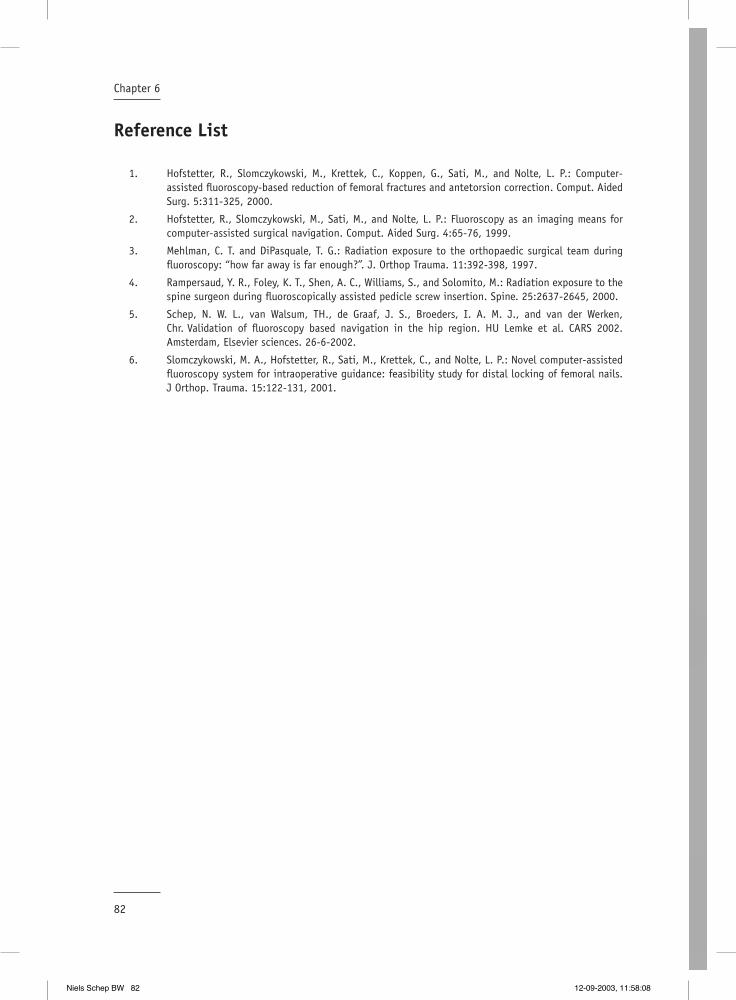
82
Chapter 6
Reference List
1. Hofstetter, R., Slomczykowski, M., Krettek, C., Koppen, G., Sati, M., and Nolte, L. P.: Computer-assisted fl uoroscopy-based reduction of femoral fractures and antetorsion correction. Comput. Aided Surg. 5:311-325, 2000.
2. Hofstetter, R., Slomczykowski, M., Sati, M., and Nolte, L. P.: Fluoroscopy as an imaging means for computer-assisted surgical navigation. Comput. Aided Surg. 4:65-76, 1999.
3. Mehlman, C. T. and DiPasquale, T. G.: Radiation exposure to the orthopaedic surgical team during fl uoroscopy: “how far away is far enough?”. J. Orthop Trauma. 11:392-398, 1997.
4. Rampersaud, Y. R., Foley, K. T., Shen, A. C., Williams, S., and Solomito, M.: Radiation exposure to the spine surgeon during fl uoroscopically assisted pedicle screw insertion. Spine. 25:2637-2645, 2000.
5. Schep, N. W. L., van Walsum, TH., de Graaf, J. S., Broeders, I. A. M. J., and van der Werken, Chr. Validation of fl uoroscopy based navigation in the hip region. HU Lemke et al. CARS 2002. Amsterdam, Elsevier sciences. 26-6-2002.
6. Slomczykowski, M. A., Hofstetter, R., Sati, M., Krettek, C., and Nolte, L. P.: Novel computer-assisted fl uoroscopy system for intraoperative guidance: feasibility study for distal locking of femoral nails. J Orthop. Trauma. 15:122-131, 2001.
Niels Schep BW 82 12-09-2003, 11:58:08
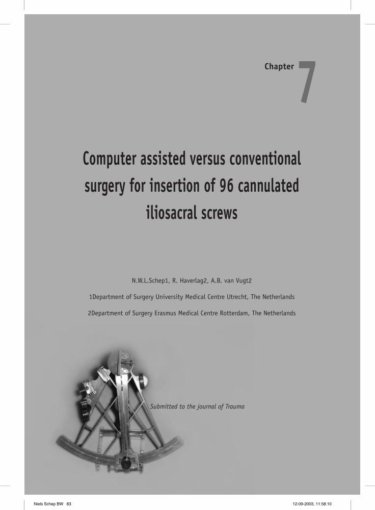
Computer assisted versus conventional surgery for insertion of 96 cannulated
iliosacral screws
7Chapter
Submitted to the journal of Trauma
N.W.L.Schep1, R. Haverlag2, A.B. van Vugt2
1Department of Surgery University Medical Centre Utrecht, The Netherlands
2Department of Surgery Erasmus Medical Centre Rotterdam, The Netherlands
Niels Schep BW 83 12-09-2003, 11:58:10

Niels Schep BW 84 12-09-2003, 11:58:10

85
Computer assisted versus conventional surgery for insertion of 96 cannulated iliosacral screws
Summary
Objective: The purpose of this study was to assess the value of fl uoroscopy based Computer
Assisted Surgery (CAS) for the insertion of iliosacral screws. The results of CAS were compared
with the results of a conventionally operated prospective control group. Endpoints of this
study were fl uoroscopy time, guidewire insertion time operation time and complication
rate.
Patients and Methods: The study group consisted of 24 patients with post partum pelvic
pain syndrome. All patients were treated with a stabilisation of the pelvic ring by means
of an anterior plate fi xation and autologous tricortical bone graft as well as two iliosacral
screws bilaterally. Consequently, the results of 48 versus 48 iliosacral screw fi xations could
be evaluated. Conventionally operated patients were turned from the supine to the prone
position intraoperatively, whereas CAS operated patients were operated in the supine
position. One surgeon performed all operations.
Results: The fl uoroscopy time in the CAS group was 0.7 min. versus 1.8 min. in the
conventional treated group (P<0.01). The mean insertion time for four guidewires was 20.2
min in the CAS versus 19.4 min in the conventional operated group (P=0.6). The mean
operation time in the CAS group was 97 min. and 116 min. in the conventional group
(P=0.03). In the CAS group one patient had pain and a sensory defi cit of S2 postoperatively.
The Fisher’s exact test showed no difference in complication rate between the two groups
(P=0.26).
Conclusions: This study shows that CAS is a save technique for insertion of iliosacral screws.
The fl uoroscopy time is decreased with a factor 2.5. The loss in operation time using CAS was
due to fact that patients were operated in the supine position during the whole procedure.
Guide wire insertion time was similar in both groups, however, in the future CAS may
accelerate the procedure.
Niels Schep BW 85 12-09-2003, 11:58:11

Niels Schep BW 86 12-09-2003, 11:58:12
87
Computer assisted versus conventional surgery for insertion of 96 cannulated iliosacral screws
Introduction
Percutaneous internal fi xation of the posterior pelvic ring with iliosacral screws was originally
described by Matta et al.(1) The percutaneous technique has become popular with the advent
of cannulated screws and improved fl uoroscopic imaging.(2,3) Advantages of percutaneous
screw fi xation include minimal invasion of soft tissue, limited blood loss and decreased
infection rates.(3,4) During the operation, a guidewire for the cannulated screw is drilled
across the ilium and targeted in the fi rst or second sacral vertebral body, using intraoperative
fl uoroscopic control.
When using intraoperative fl uoroscopy, only a one single two-dimensional (2D) image plane
is visualised on a specifi c moment. Whereas, at least three image planes, inlet, outlet and
lateral are required to allow accurate insertion of the guidewires. This leads to repetitive
position changes of the C-arm intraoperatively, resulting in an important radiation exposure
for both patient and surgical team.(5-7) Moreover, this technique requires a high degree of
“three-dimensional thinking (3D)” and an expert knowledge of the anatomy of the pelvis.
These arguments make percutaneous iliosacral screw placement a demanding operation
with risk of injury of the lumbosacral nerve roots, perforation of the iliac vessels, and the
peritoneal cavity.(3,4,8-10)
The disadvantages of the conventional technique may be solved by fl uoroscopy based computer
assisted surgery (CAS). With this technique the virtual position of surgical instruments is
superimposed on multiple single shot radiographic images in real time. Consequently, the
position and direction of a guidewire can be visualised in different fl uoroscopic images
simultaneously.(11,12) Hypothetically, this way of operating may result in accurate screw
placement, reduction of radiation exposure and loss of operation time. Fluoroscopy based
CAS for the insertion of iliosacral screws in 35 pelvic models was described by Hinsche et
al. This study showed a reduction in fl uoroscopy time and an accuracy equivalent with the
conventional technique.(12)
The purpose of this study was to assess the value of fl uoroscopy based CAS for the insertion
of iliosacral screws in the clinical situation. The results of CAS were compared with the
results of a conventionally operated prospective control group. Endpoints of this study were
fl uoroscopy time, guidewire insertion time operation time and complication rate.
Niels Schep BW 87 12-09-2003, 11:58:12
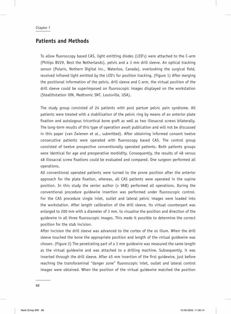
88
Chapter 7
Patients and Methods
To allow fl uoroscopy based CAS, light emitting diodes (LED’s) were attached to the C-arm
(Philips BV29, Best the Netherlands), pelvis and a 3 mm drill sleeve. An optical tracking
sensor (Polaris, Nothern Digital inc., Waterloo, Canada), overlooking the surgical fi eld,
received infrared light emitted by the LED’s for position tracking. (Figure 1) After merging
the positional information of the pelvis, drill sleeve and C-arm, the virtual position of the
drill sleeve could be superimposed on fl uoroscopic images displayed on the workstation
(Stealthstation iON, Medtronic SNT, Louisville, USA).
The study group consisted of 24 patients with post partum pelvic pain syndrome. All
patients were treated with a stabilisation of the pelvic ring by means of an anterior plate
fi xation and autologous tricortical bone graft as well as two iliosacral screws bilaterally.
The long-term results of this type of operation await publication and will not be discussed
in this paper (van Zwienen et al., submitted). After obtaining informed consent twelve
consecutive patients were operated with fl uoroscopy based CAS. The control group
consisted of twelve prospective conventionally operated patients. Both patients groups
were identical for age and preoperative morbidity. Consequently, the results of 48 versus
48 iliosacral screw fi xations could be evaluated and compared. One surgeon performed all
operations.
All conventional operated patients were turned to the prone position after the anterior
approach for the plate fi xation, whereas, all CAS patients were operated in the supine
position. In this study the senior author (v VAB) performed all operations. During the
conventional procedure guidewire insertion was performed under fl uoroscopic control.
For the CAS procedure single inlet, outlet and lateral pelvic images were loaded into
the workstation. After length calibration of the drill sleeve, its virtual counterpart was
enlarged to 200 mm with a diameter of 3 mm. to visualise the position and direction of the
guidewire in all three fl uoroscopic images. This made it possible to determine the correct
position for the stab incision.
After incision the drill sleeve was advanced to the cortex of the os ilium. When the drill
sleeve touched the bone the appropriate position and length of the virtual guidewire was
chosen. (Figure 2) The penetrating part of a 3 mm guidewire was measured the same length
as the virtual guidewire and was attached to a drilling machine. Subsequently, it was
inserted through the drill sleeve. After 45 mm insertion of the fi rst guidewire, just before
reaching the transforaminal “danger zone” fl uoroscopic inlet, outlet and lateral control
images were obtained. When the position of the virtual guidewire matched the position
Niels Schep BW 88 12-09-2003, 11:58:14

89
Computer assisted versus conventional surgery for insertion of 96 cannulated iliosacral screws
of the guidewire in the fl uoroscopic images the procedure was continued using CAS. Every
time a guidewire was positioned its virtual position was drawn in the fl uoroscopic images.
(Figure 3) When, all four guidewires were positioned, 6.5 mm cannulated screws (Biomet,
Warsaw, USA) were inserted and correct positioning of the screws was confi rmed with
fl uoroscopy. Only a small number of patients were treated with screws positioned in the
second sacral vertebral body, two screws in the CAS and eight screws in the conventional
group.
FIGURE 1A An optical tracking sensor(Polaris, Nothern Digital inc., Waterloo,Canada), overlooking the surgical fi eld,received infrared light emitted by the LED’s for position tracking. LED’s were fi xated on the pelvis, C-arm and drillsleeve.
FIGURE 1B
The patients reference frame is fi rmly attached in the pelvis.
Niels Schep BW 89 12-09-2003, 11:58:15
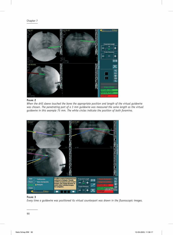
90
Chapter 7
FIGURE 2When the drill sleeve touched the bone the appropriate position and length of the virtual guidewire was chosen. The penetrating part of a 3 mm guidewire was measured the same length as the virtual guidewire in this example 75 mm. The white circles indicate the position of both foramina.
FIGURE 3Every time a guidewire was positioned its virtual counterpart was drawn in the fl uoroscopic images.
Niels Schep BW 90 12-09-2003, 11:58:17

91
Computer assisted versus conventional surgery for insertion of 96 cannulated iliosacral screws
Intraoperatively, system set up time, fl uoroscopy time, guidewire insertion time and total
operation time were scored. The operation time was defi ned from the skin incision for the
anterior internal fi xation until suturing was completed. Postoperatively the patients were
followed up for operation related complications. The time period for these complications to
occur was defi ned within 30 days after surgery.
All results were evaluated with SPSS 10.1 for Windows (SPSS, Inc, Chicago). A Mann Whitney
test was performed to test the hypothesis of no difference in fl uoroscopy time, guidewire
insertion time and total operation time. P< 0.05 was considered signifi cant. Differences in
complication ratio were evaluated with the Fisher’s exact test.
Results
In the conventional and in the CAS group the average age was 36 years (range 26-47 years).
The mean system setup time was 7.8 min. (range 5-17 min.). The fl uoroscopy time in the CAS
group showed to be 0.7 min. versus 1.8 min. in the conventional treated group (P<0.01).
The mean insertion time for four guidewires was 20.2 min in the CAS versus 19.4 min in the
conventional operated group (P=0.6). The mean operation time in the CAS group was 97 min.
and 116 min. in the conventional group (P=0.03).
In the CAS group one patient had pain and a sensory defi cit of S2 postoperatively. The
control CT scan showed a marginal protrusion of the screw treads into the sacral canal
of S2. After the screw was extracted the complaints resolved completely. A total of three
patients developed a complication in the conventional group. Two patients had a posterior
hematoma. In one of these cases a reoperation was indicated. The other patient had a
postoperative sensory defi cit, which resolved completely without intervention. The Fisher’s
exact test showed no difference in complication rate between the two groups (P=0.26).
Discussion
Fluoroscopy based navigation is an upcoming technology in orthopaedic and trauma surgery
since 1999. The purpose of this study was to assess the value of fl uoroscopy based CAS for
the insertion of iliosacral screws in the clinical situation. The results of the CAS procedure
were compared with the results of a conventionally operated prospective control group.
Niels Schep BW 91 12-09-2003, 11:58:20
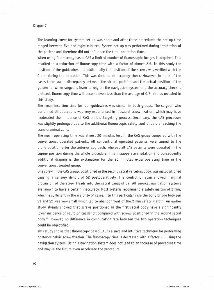
92
Chapter 7
The learning curve for system set-up was short and after three procedures the set-up time
ranged between fi ve and eight minutes. System set-up was performed during intubation of
the patient and therefore did not infl uence the total operation time.
When using fl uoroscopy based CAS a limited number of fl uoroscopic images is acquired. This
resulted in a reduction of fl uoroscopy time with a factor of almost 2.5. In this study the
position of the guidewires and additionally the position of the screws was verifi ed with the
C-arm during the operation. This was done as an accuracy check. However, in none of the
cases there was a discrepancy between the virtual position and the actual position of the
guidewire. When surgeons learn to rely on the navigation system and the accuracy check is
omitted, fl uoroscopy time will become even less than the average of 0.7 min. as revealed in
this study.
The mean insertion time for four guidewires was similar in both groups. The surgeon who
performed all operations was very experienced in iliosacral screw fi xation, which may have
moderated the infl uence of CAS on the targeting process. Secondary, the CAS procedure
was slightly prolonged due to the additional fl uoroscopic safety control before reaching the
transforaminal zone.
The mean operating time was almost 20 minutes less in the CAS group compared with the
conventional operated patients. All conventional operated patients were turned to the
prone position after the anterior approach, whereas all CAS patients were operated in the
supine position during the whole procedure. This intraoperative rotation and consequently
additional draping is the explanation for the 20 minutes extra operating time in the
conventional treated group.
One screw in the CAS group, positioned in the second sacral vertebral body, was malpositioned
causing a sensory defi cit of S2 postoperatively. The control CT scan showed marginal
protrusion of the screw treads into the sacral canal of S2. All surgical navigation systems
are known to have a certain inaccuracy. Most systems recommend a safety margin of 2 mm,
which is suffi cient in the majority of cases.13 In this particular case the bony bridge between
S1 and S2 was very small which led to abandonment of the 2 mm safety margin. An earlier
study already showed that screws positioned in the fi rst sacral body have a signifi cantly
lower incidence of neurological defi cit compared with screws positioned in the second sacral
body.14 However, no difference in complication rate between the two operation techniques
could be objectifi ed.
This study shows that fl uoroscopy based CAS is a save and intuitive technique for performing
posterior pelvic screw fi xation. The fl uoroscopy time is decreased with a factor 2.5 using the
navigation system. Using a navigation system does not lead to an increase of procedure time
and may in the future even accelerate the procedure
Niels Schep BW 92 12-09-2003, 11:58:21
93
Computer assisted versus conventional surgery for insertion of 96 cannulated iliosacral screws
Reference List
1. Matta, J. M. and Saucedo, T.: Internal fi xation of pelvic ring fractures. Clin. Orthop.83-97, 1989.
2. Routt, M. L., Meier M., and Kregor, P. J.: Percutaneous iliosacral screws with the patient supine technique. Oper Tech Orthop.35-45, 1993.
3. Routt, M. L., Jr., Kregor, P. J., Simonian, P. T., and Mayo, K. A.: Early results of percutaneous iliosacral screws placed with the patient in the supine position. J. Orthop. Trauma. 9:207-214, 1995.
4. Shuler, T. E., Boone, D. C., Gruen, G. S., and Peitzman, A. B.: Percutaneous iliosacral screw fi xation: early treatment for unstable posterior pelvic ring disruptions. J. Trauma. 38:453-458, 1995.
5. Mehlman, C. T. and DiPasquale, T. G.: Radiation exposure to the orthopaedic surgical team during fl uoroscopy: “how far away is far enough?”. J. Orthop Trauma. 11:392-398, 1997.
6. Sanders, R., Koval, K. J., DiPasquale, T., Schmelling, G., Stenzler, S., and Ross, E.: Exposure of the orthopaedic surgeon to radiation. J. Bone Joint Surg. Am. 75:326-330, 1993.
7. Rampersaud, Y. R., Foley, K. T., Shen, A. C., Williams, S., and Solomito, M.: Radiation exposure to the spine surgeon during fl uoroscopically assisted pedicle screw insertion. Spine. 25:2637-2645, 2000.
8. Ebraheim, N. A., Coombs, R. J., Hoefl inger, M. J., and Jackson, W. T.: A pitfall of radiologic evaluation of sacroiliac joint screw positioning. Orthopedics. 16:616-618, 1993.
9. Pattee, G. A., Bohlman, H. H., and McAfee, P. C.: Compression of a sacral nerve as a complication of screw fi xation of the sacro-iliac joint. A case report. J. Bone Joint Surg. Am. 68:769-771, 1986.
10. Templeman, D., Schmidt, A., Freese, J., and Weisman, I.: Proximity of iliosacral screws to neurovascular structures after internal fi xation. Clin. Orthop.194-198, 1996.
11. Hofstetter, R., Slomczykowski, M., Sati, M., and Nolte, L. P.: Fluoroscopy as an imaging means for computer-assisted surgical navigation. Comput. Aided Surg. 4:65-76, 1999.
12. Hinsche, A. F., Giannoudis, P. V., and Smith, R. M.: Fluoroscopy-based multiplanar image guidence for insertion of sacroiliac screws. Clin. Orthop. 395:135-144, 2001.
13. Schep, N. W. L., van Walsum, TH., de Graaf, J. S., Broeders, I. A. M. J., and van der Werken, Chr. Validation of fl uoroscopy based navigation in the hip region. HU Lemke et al. CARS 2002, Springer Berlin, 247-251
14. van den Bosch, E. W., van Zwienen, C. M., and van Vugt, A. B.: Fluoroscopic positioning of sacroiliac screws in 88 patients. J. Trauma. 53:44-48, 2002.
Niels Schep BW 93 12-09-2003, 11:58:22

Niels Schep BW 94 12-09-2003, 11:58:23

General discussion and conclusions
8Chapter
Niels Schep BW 95 12-09-2003, 11:58:23

Niels Schep BW 96 12-09-2003, 11:58:24

97
General discussion and conclusions
Discussion
Computer Assisted Surgery (CAS) is currently considered a standard of care in neurosurgery.
Neurosurgeons use this technique to facilitate intracranial needle biopsies, isotope
implantation and tumour resection. (2;3;9;20;21) Theoretically, Orthopaedic and Trauma surgery
are also well suited for this technique. Brain tissue may deform during manipulation by the
surgeon. This intra-operative change of anatomy caused by manipulation is an important
problem during CAS in neurosurgery. Bone tissue, however, is almost not deformable and
therefore is very appropriate for CAS, based on pre- or intra-operatively obtained images.
In CAS improved visualisation is combined with computer tracking of surgical instruments.
This feature promises enhanced accuracy and consequently less morbidity combined with a
reduction in radiation exposure.
The goal of this thesis was to evaluate the hypothesis of high accuracy and reproducibility
of CAS. This was achieved by performing a series of tests. All tests were performed within
an experimental and clinical setting. To test the hypothesis the following questions were
answered.
1. How exact represents the displayed position of an instrument in fl uoroscopic images the
real situation?
2. Does CAS reduce surgical variance and therewith improve the reproducibility of (minimal
invasive) orthopaedic and trauma surgery ?
3. Are there clinical benefi ts using CAS during positioning of implants?
1. How exact represents the displayed position of an instrument in fl uoroscopic images the real situation?
Fluoroscopic images are frequently used for navigation within bone tissue. During CAS the
position of tracked instruments is superimposed on these fl uoroscopic images after image
acquisition (11)
Surgeons using this technique have to rely on the accuracy of the navigation system, since
the only intraoperative feedback on the “true” position of the instrument is the position
of its virtual counterpart superimposed on the fl uoroscopic images. Lack of correspondence
between this virtual position and the true position may lead to severe complications.
Niels Schep BW 97 12-09-2003, 11:58:24
98
Chapter 8
In Chapter 3 the accuracy of the fl uoroscopy based navigation system used in our hospital
(Medivision, Oberdorf, CH.) was evaluated in a laboratory study performed in 20 sawbones of
a proximal femur. The displayed virtual position of a reamer within the fl uoroscopic images
was compared with its true position in a predefi ned cutplane in the middle of the femoral
neck. The virtual position of the reamer appeared to be reliable in 97% of cases when
considering an inaccuracy of ≤ 2mm as clinically irrelevant. In nine out of 360 measurements
a difference of more than 2 mm was found. In these cases it seemed most likely that the
Dynamic Reference Frame (DRF) was moved relative to the sawbone during the experiment.
In conclusion, the fl uoroscopy based navigation system that was validated in this study
provided a reliable virtual position of the reamer in the femoral neck compared with its true
position. When a fi rm connection between the DRF and the target bone is assured the system
can be safely used.
2. Does CAS reduce surgical variance and therewith improve the reproducibility of (minimal invasive) orthopaedic and trauma surgery ?
An important objective of CAS is to improve the reproducibility of a procedure. To achieve
this goal it will be necessary to reduce surgical variance between surgeons, performing
identical operations. In the experimental part of our study we tested the hypothesis that
CAS enhances reproducibility in the treatment of femoral shaft fractures and ACL graft
placement.
Computer assisted anteversion and length control in closed nailing of femoral shaft fractures
Locked intramedullary nailing is commonly used for the treatment of femoral shaft fractures.
An important complication of the conventional limited invasive nailing procedure is
malrotation of the stabilised femur. Rotation differences of 15° or more were found in
19 % and leg length discrepancies of more than 10 mm in 9 % of patients. (4;5)
Hofstetter and others developed a CAS module for the surgical treatment of femoral shaft
fractures.(10) This concept allows intraoperative assessment and control of rotation and
length. Potential advantages of this technique are reduction of postoperative torsion
deformities and leg length discrepancies. Chapter 4 presents the results of a cadaver study
investigating the reliability and reproducibility of femoral anteversion angles and lengths
provided by the navigation system (Medivision, Oberdorf, CH.).
Niels Schep BW 98 12-09-2003, 11:58:24

99
General discussion and conclusions
To determine the rotation and length of the femoral shaft different landmarks were manually
defi ned in six fl uoroscopic images displayed on the CAS system. This was performed for
each femur by three investigators. To evaluate the anteversion angels and femoral lengths
provided by the navigation system, a golden standard based on CT data was developed. The
golden standard allowed navigation through coronal, sagittal and axial planes. The three
investigators defi ned the same landmarks as in the fl uoroscopic images. Inter observer
variability was assessed for the fl uoroscopy (CAS) and CT based method.
The mean inter investigator variance using the CAS method was 5.5 º (1-11) for anteversion
and 5.2 mm (2-10) for femoral length. The CT based method showed a mean inter investigator
variance of 3.1º (0.41-7.97) for anteversion and 2.5 mm (0.78-5.94) for length. The mean
difference in length measurements between the CAS and CT based method was < 1 cm. The
variation in measured anteversion angles between the CAS and CT based method showed a
mean difference of 13º degrees with a maximum 26º.
In summary the length measurements provided by the navigation system showed to
be reproducible and accurate enough for clinical use. The rotation measurements were
reproducible with a difference of almost six degrees but not accurate enough to prevent
malrotation considering the CT based method as the gold standard. When using the
anteversion angle of the contralateral (unbroken) extremity as a template for the reduction
the inter investigator variance may be enough to avoid outliers. This will be the subject for
further research.
Computer assisted anterior cruciate ligament graft positioning
The most critical step in arthroscopic reconstruction of a torn anterior cruciate ligament
(ACL) with a (patellar tendon) graft is placement of the femoral and tibial tunnels, in which
the graft is secured. An accurate position of these tunnels can minimise stretching of the
graft and decrease the risk of impingement against the roof of the femoral notch during
extension of the knee. (1) Graft over stretching and impingement may lead to graft failure.
(22)
Desenne et al. introduced a computer system to predict notch impingement and graft
elongation. (6) Intraoperatively, the surgeon defi ned the femoral and tibial attachment
sides of the graft. Subsequently, the computer created a virtual model of the knee. Notch
impingement and elongation for selected graft positioning could be predicted by displaying
the kinematics of a virtual ACL on a monitor, before the actual drilling of the tunnels. (18)
Theoretically, this way of virtual planning should reduce the variance between surgeons
and leads to a more accurate and reproducible procedure. In Chapter 5 this hypothesis was
Niels Schep BW 99 12-09-2003, 11:58:25

100
Chapter 8
tested and inter- surgical variance was assigned in mm. Next, computer assisted virtual
planning was compared with a conventional procedure in the same knee.
Three surgeons with a different experience level participated. Computer assisted ACL
planning was compared between two surgeons in the same cadaver knee. The computer
system outlined an impingement area and visualised graft elongation in a virtual manner.
Both surgeons positioned the virtual graft in such a way that impingement was avoided
and graft elongation was < 4 mm during fl exion and extension. A third surgeon performed a
conventional procedure on the same cadaver knee. The position and kinematics of this graft
were also analysed with the computer system.
The difference between the two planning procedures proved to be approximately 5 mm in
both tibia and femur. The experience level of the surgeon had no effect on the position
of these virtual tunnels. The mean distance between the planned and the conventional
procedures proved to be more than six mm for both the tibia as the femoral tunnel. The
conventional procedure showed impingement in three out of twelve knees and an elongation
of more than four mm in two additional knees. The less experienced surgeon was responsible
for two impingement cases. The three knees with an elongation of more than four mm were
equally distributed among the three surgeons.
This study indicates that computer assisted planning may reduce the inter-surgical variance
to 5 mm for positioning both tunnels. Moreover, the experience level of the surgeon did
not effect the planning process. Less experienced surgeons and residents may benefi t from
virtual graft planning to reduce the number of malpositioned tunnels.
3. Are there clinical benefi ts using CAS during positioning of implants?
The results of the accuracy study described in Chapter 3 led to the clinical implementation
of fl uoroscopy based navigation for internal fi xation of femoral neck fractures with a Dynamic
Hip Screw (DHS). This type of operation was selected because it is a relative simple and
frequently performed procedure and therefore well suited to gain clinical experience.
Additionally, the clinical value of fl uoroscopy based CAS for the insertion of iliosacral screws
was evaluated. The results of CAS iliosacral screw fi xation were compared with the results of
a conventionally operated prospective control group.
Niels Schep BW 100 12-09-2003, 11:58:26
101
General discussion and conclusions
Internal fi xation of femoral neck fractures with computer assisted surgery
Chapter 6 describes the feasibility and pitfalls of CAS in the treatment of femoral neck
fractures with a DHS in a small patients group. After the accuracy study we treated seven
patients to evaluate the feasibility of this new technique.
All seven patients were operated in supine position on a fracture table. After closed reduction
of the fracture the injured leg was brought in slight traction. In four patients the DRF was
attached rigidly with a Steinmann pin in the iliac crest and in three patients in the greater
trochanter. Subsequently, AP and AX fl uoroscopic images were obtained and loaded into the
workstation (Medivision, Oberdorf, Switzerland).
To achieve CAS in the hip region two standard instruments were modifi ed. First, a procedure
dedicated aiming arm was designed, based on the standard 135º aiming device, holding an
8 mm channel for the DHS reamer. This enabled the surgeon to drill directly in the correct
angle. Secondly, the standard cannulated 8 mm DHS reamer was made non-cannulated by
fi xating a K-wire in the central hole, which exceeded the tip of the drillbit by two mm. The
tip of this K-wire was pressed in the lateral femoral cortex just before drilling, establishing
better grip on the lateral femoral cortex. After drilling the insertion hole, the hip screw and
a one hole 135° side plate were inserted by standard technique.
One CAS procedure failed because the position and direction of the virtual drill undoubtedly
did not correspond with the true anatomic position of the drillbit. In the fi rst four patients
we tested the hypothesis that traction of the affected limb could establish a rigid relation
between the pelvis and proximal femur. Therefore, the DRF was attached in the iliac crest.
This made it simple to obtain a straight line of sight between the opto-electric camera and
the DRF’s of the DRF during image acquisition and drilling. However, non-correspondence
between the virtual drill and the clinical situation in the patient, described above, made
it clear that during manipulation this fi xed relationship could not be guaranteed in all
situations. This example emphasizes once more that it is obligatory to fi x the patient’s DRF
in the operated bone.
In one patient the tip of the hip screw was positioned to deeply in the femoral head. In
retrospect, it was not possible to clearly identify the contours of the femoral head on the
uploaded fl uoroscopic images. Moreover, in this set up the surgeon had to drill instantaneously
through an 8 mm aiming device. In clinical practice it seemed to be complex to hold the
aiming device and the drilling machine while at the same time maintaining enough pressure
on the lateral femoral cortex. Repeatedly, the drill slid from the lateral femoral cortex. The
absence of a K-wire can be held responsible for this dilemma.
Niels Schep BW 101 12-09-2003, 11:58:26
102
Chapter 8
Our limited experience showed that fl uoroscopy based navigation in the treatment of femoral
neck fractures with a DHS is feasible. However, the technique used in this study was to
complicated to use in daily practice. The possibility to navigate guidewires will probably
make the procedure more intuitive and closer to the conventional operation.
Computer assisted surgery for insertion of cannulated iliosacral screws
In Chapter 7 fl uoroscopy based CAS for the insertion of iliosacral screws was evaluated.
Working with CAS may offer additional benefi ts as reduction in operation time and radiation
exposure. To test this hypothesis the results of CAS were compared with the results of a
conventionally operated prospective control group. Endpoints of this study were fl uoroscopy
time, guidewire insertion time and complication rate.
The operative results of 48 versus 48 identical patients with post partum pelvic pain
syndrome were evaluated. All patients were treated with a stabilisation of the pelvic ring by
means of symphysal plating combined with an autologous tricortical bone graft as well as
two iliosacral screws bilaterally.
With the CAS technique used in this study (Stealthstation iON, Medtronic SNT, Louisville, USA)
it was possible to visualise the position and direction of a guidewire in three fl uoroscopic
images (inlet,outlet,lateral).
Fluoroscopy time was decreased with a factor of 2.5 in the CAS group (mean 0.7 min.). The
mean insertion time for four guidewires was similar in both groups. However, during the
CAS procedure an additional fl uoroscopic safety control was performed before reaching the
transforaminal zone. During these safety checks no discrepancy between the virtual position
and the actual position of the guidewire was confi rmed. No difference in complication rate
between the two operation techniques could be objectifi ed.
This study showed that fl uoroscopy based CAS is a save and intuitive technique for performing
posterior pelvic screw fi xation. The fl uoroscopy time was decreased with a factor 2.5. The use
of the navigation system did not lead to a longer procedure time and may in the future even
accelerate the procedure when the intraoperative safety check is omitted.
Conclusions
The potential advantages of Computer Assisted Surgery (CAS) are obvious, increasing the
accuracy, safety and reproducibility of surgical interventions. Moreover, CAS technologies
Niels Schep BW 102 12-09-2003, 11:58:27
103
General discussion and conclusions
offer additional benefi ts as lower radiation exposure through navigation in one shot
fl uoroscopic images.
This thesis showed that fl uoroscopy based surgical navigation is accurate enough to
use in experimental and clinical situations. The position of a surgical instrument can
be displayed virtually within fl uoroscopic images of bone tissue with less than 2 mm
inaccuracy in 97% of the cases.
However, when CAS was used to treat simple femoral neck fractures with a DHS the
surgeons encountered several technical hitches. They had to operate with different and
modifi ed instruments to create an environment, which allowed surgical navigation in the
proximal femur. The result was a feasible procedure that was, however, inadequate for
daily clinical practice. This study clearly showed that CAS has to be intuitive and easy to
use before it is embedded in standard surgical practice.
In fracture care the positioning of guidewires is a frequently performed procedure when
performing osteosynthesis. Navigation of guidewire insertion led to an intuitive and
straightforward procedure in iliosacral screw fi xation. This was shown when the results
of CAS iliosacral screw fi xation were compared with those in a conventionally operated
control group. Important benefi ts of the computer-assisted procedure were revealed in
this study: fl uoroscopy time was shortened with a factor 2.5, CAS facilitated the targeting
process in diverse image planes while it is reasonable to expect that CAS will accelerate
this procedure in the future.
The results of the experimental studies described in this thesis show an opportunity to
infl uence surgical variance in a positive way. CAS for intramedullary fi xation of femoral
shaft fractures offers the opportunity to exactly locate the insertion point for the nail on
the proximal femur and to perform distal locking effectively. However, computer assisted
anteversion control as described in our study is not yet evolved to the stage of save
clinical implementation.
Considering, computer-assisted planning of an ACL graft, it was shown that surgical
variance is about fi ve mm for the tunnels both in the femur and tibia. Whether this
accuracy is enough to reduce the outliers and to reach a better clinical outcome in ACL
reconstruction is uncertain.
Image guided surgical navigation will become standard in various fi elds of orthopaedic
and trauma surgery in the future. These fi elds will be most likely pedicle screw placement
in spine surgery, sacroiliacal fi xation, reduction of long bone fractures and knee and
hip prosthetic replacement. Navigation based on 3D fl uoroscopic images is the latest
technology and will lead to new clinical applications.
Niels Schep BW 103 12-09-2003, 11:58:28
104
Chapter 8
In summary fl uoroscopy based CAS is accurate enough to rely on in experimental and
clinical situations. This thesis proved several clinical benefi ts for CAS when used for
navigated guidewire insertion in iliosacral screw fi xation compared with the conventional
technique. The CAS femoral anteversion control module must be improved before clinical
use. Computer-assisted ACL grafting has to be evaluated in a controlled study. However,
it is to be expected that CAS will soon evaluate into a clinically accepted and mandatory
technique in some fi elds of orthopaedic and trauma surgery.
Niels Schep BW 104 12-09-2003, 11:58:29
105
General discussion and conclusions
Reference List
1. Amis, A. A. and Jakob, R. P.: Anterior cruciate ligament graft positioning, tensioning and twisting. Knee. Surg. Sports Traumatol. Arthrosc. 6 Suppl 1:S2-12, 1998.
2. Apuzzo, M. L. and Sabshin, J. K.: Computed tomographic guidance stereotaxis in the management of intracranial mass lesions. Neurosurgery. 12:277-285, 1983.
3. Barnett, G. H., Kormos, D. W., Steiner, C. P., and Weisenberger, J.: Use of a frameless, armless stereotactic wand for brain tumor localization with two-dimensional and three-dimensional neuroimaging. Neurosurgery. 33:674-678, 1993.
4. Braten, M., Terjesen, T., and Rossvoll, I.: Torsional deformity after intramedullary nailing of femoral shaft fractures. Measurement of anteversion angles in 110 patients. J. Bone Joint Surg. Br. 75:799-803, 1993.
5. Braten, M., Terjesen, T., and Rossvoll, I.: Femoral shaft fractures treated by intramedullary nailing. A follow-up study focusing on problems related to the method. Injury. 26:379-383, 1995.
6. Dessenne, V., Lavallee, S., Julliard, R., Orti, R., Martelli, S., and Cinquin, P.: Computer-assisted knee anterior cruciate ligament reconstruction: fi rst clinical tests. J. Image Guid. Surg. 1:59-64, 1995.
7. Fineberg, M. S., Zarins, B., and Sherman, O. H.: Practical considerations in anterior cruciate ligament replacement surgery. Arthroscopy. 16:715-724, 2000.
8. Frank, C. B. and Jackson, D. W.: The science of reconstruction of the anterior cruciate ligament. J. Bone Joint Surg. Am. 79:1556-1576, 1997.
9. Gildenberg, P. L., Kaufman, H. H., and Murthy, K. S.: Calculation of stereotactic coordinates from the computed tomographic scan. Neurosurgery. 10:580-586, 1982.
10. Hofstetter, R., Slomczykowski, M., Krettek, C., Koppen, G., Sati, M., and Nolte, L. P.: Computer-assisted fl uoroscopy-based reduction of femoral fractures and antetorsion correction. Comput. Aided Surg. 5:311-325, 2000.
11. Hofstetter, R., Slomczykowski, M., Sati, M., and Nolte, L. P.: Fluoroscopy as an imaging means for computer-assisted surgical navigation. Comput. Aided Surg. 4:65-76, 1999.
12. Kamimura, M., Ebara, S., Itoh, H., Tateiwa, Y., Kinoshita, T., and Takaoka, K.: Accurate pedicle screw insertion under the control of a computer-assisted image guiding system: laboratory test and clinical study. J. Orthop. Sci. 4:197-206, 1999.
13. Laine, T., Lund, T., and Ylikoski, M. Pedicle screw insertion with and without Computer Assistence-Two year clinical results of a randomised controlled study in 100 patients. 2002.
14. Laine, T., Schlenzka, D., Makitalo, K., Tallroth, K., Nolte, L. P., and Visarius, H.: Improved accuracy of pedicle screw insertion with computer-assisted surgery. A prospective clinical trial of 30 patients. Spine. 22:1254-1258, 1997.
15. Ludwig, S. C., Kramer, D. L., Balderston, R. A., Vaccaro, A. R., Foley, K. F., and Albert, T. J.: Placement of pedicle screws in the human cadaveric cervical spine: comparative accuracy of three techniques. Spine. 25:1655-1667, 2000.
16. Merloz, P., Tonetti, J., Eid, A., Faure, C., Lavallee, S., Troccaz, J., Sautot, P., Hamadeh, A., and Cinquin, P.: Computer-assisted spine surgery. Clin. Orthop.86-96, 1997.
17. Merloz, P., Tonetti, J., Pittet, L., Coulomb, M., Lavallee, S., and Sautot, P.: Pedicle screw placement using image guided techniques. Clin. Orthop.39-48, 1998.
18. sati, M., Staubli, H. U., Bourquin, Y., Kunz, M., Kasermann, S., and Nolte, L. P.: Clinical integration of computer-assisted technology for arthroscopic anterior cruciate ligament reconstruction. Operat Tech Orthopaed.40-49, 2000.
Niels Schep BW 105 12-09-2003, 11:58:29
106
Chapter 8
19. Schwarzenbach, O., Berlemann, U., Jost, B., Visarius, H., Arm, E., Langlotz, F., Nolte, L. P., and Ozdoba, C.: Accuracy of computer-assisted pedicle screw placement. An in vivo computed tomography analysis. Spine. 22:452-458, 1997.
20. Tan, K. K., Grzeszczuk, R., Levin, D. N., Pelizzari, C. A., Chen, G. T., Erickson, R. K., Johnson, D., and Dohrmann, G. J.: A frameless stereotactic approach to neurosurgical planning based on retrospective patient-image registration. Technical note. J. Neurosurg. 79:296-303, 1993.
21. Watanabe, E., Watanabe, T., Manaka, S., Mayanagi, Y., and Takakura, K.: Three-dimensional digitizer (neuronavigator): new equipment for computed tomography-guided stereotaxic surgery. Surg. Neurol. 27:543-547, 1987.
22. Zavras, T. D., Race, A., Bull, A. M., and Amis, A. A.: A comparative study of ‘isometric’ points for anterior cruciate ligament graft attachment. Knee. Surg. Sports Traumatol. Arthrosc. 9:28-33, 2001.
Niels Schep BW 106 12-09-2003, 11:58:30
Samenvatting en conclusies
Niels Schep BW 107 12-09-2003, 11:58:30

Niels Schep BW 108 12-09-2003, 11:58:30

109
Samenvatting en conclusies
Piloten vertrouwen voor een belangrijk deel op hun visuele waarneming tijdens het landen
van een vliegtuig. Wanneer slechte weersomstandigheden het zicht beperken vertrouwen
ze op hun navigatie-instrumenten voor oriëntatie en een veilige landing. Minimaal
invasieve orthopedische en traumatologische ingrepen kunnen worden vergeleken met
het vliegen door dikke mist omdat de chirurg werkt door kleine openingen in het menselijk
lichaam. Hierdoor gaat het directe zicht op het operatiegebied en dus op de positie
van de instrumenten verloren. In deze situaties vertrouwd de chirurg op radiologische
hulpmiddelen zoals computer tomography (CT), magnetic resonance imaging (MRI) en
röntgendoorlichting.
Nadeel van deze technieken is dat positie van de instrumenten alleen wordt getoond
op het moment van beeldvorming. Dit wil zeggen dat de chirurg een momentopname
te zien krijgt. Continue beeldvorming is technisch complex en gaat gepaard met een
hoge stralingsbelasting voor zowel patiënt als chirurgisch team. Tussen de momenten
van beeldvorming in moet de chirurg vertrouwen op zijn of haar kennis van de anatomie
en driedimensionale oriëntatie. Deze situatie kan leiden tot onnauwkeurigheid en
gerelateerde morbiditeit. Het gebrek aan constante feedback over de instrumentpositie
kan tevens leiden tot een verminderde reproduceerbaarheid van identieke chirurgische
ingrepen.
Om een omgeving te creëren waarin chirurgen constant geïnformeerd zijn over de positie
van hun instrumenten in relatie tot de anatomie werden computers geïntroduceerd in de
operatiekamer. Deze manier van opereren wordt computer geassisteerde chirurgie (CAS)
ofwel navigatiechirurgie genoemd. CAS informeert de chirurg op ieder moment van de
operatie over de exacte positie van het instrumentarium ten opzichte van de anatomie. Op
deze manier weet de chirurg ten allen tijde waar hij of zij zich bevindt. Om dit mogelijk
te maken wordt de positie van het instrumentarium virtueel weergeven in radiologische
beelden. Het concept is te vergelijken met een global positioning system (GPS) wat
gebruikt wordt in de auto-industrie. De radiologische beelden dienen hier als de landkaart
waarin de positie van een instrument virtueel wordt weergegeven. Het potentiële voordeel
van deze manier van werken is een toegenomen nauwkeurigheid en een toegenomen
reproduceerbaarheid van chirurgische ingrepen.
Het doel van dit proefschrift was het evalueren van de hypothese dat CAS nauwkeuriger
is en leidt tot een toegenomen reproduceerbaarheid in combinatie met een lagere
stralingsbelasting voor patiënt en chirurgisch team. Dit werd bereikt door het
beantwoorden van de volgende vragen gedurende experimenteel en klinisch onderzoek.
Niels Schep BW 109 12-09-2003, 11:58:30

110
Chapter 8
1. Hoe exact komt de virtueel afgebeelde positie van een instrument in röntgen
doorlichtingbeelden overeen met de werkelijke situatie?
2. Reduceert CAS de chirurgische variatie en verbeterd daarmee de reproduceerbaarheid
van (minimaal invasieve) orthopedische en traumatologische ingrepen?
3. Zijn er klinische voordelen wanneer CAS gebruikt wordt voor het positioneren van
implantaten?
1. Hoe exact komt de virtueel afgebeelde positie van een instrument in röntgen doorlichtingbeelden overeen met de werkelijke situatie?
In hoofdstuk 3 wordt de nauwkeurigheid van het navigatiesysteem wat gebruikt wordt
in ons ziekenhuis (Medivision, Oberdorf, Zwitserland) geëvalueerd. Dit werd bereikt door
middel van een laboratoriumstudie in 20 plastic modellen van het proximale femur. De
virtueel afgebeelde positie van een boor werd vergeleken met de werkelijke positie.
Deze positie bleek betrouwbaar in 97% van de gevallen wanneer er vanuit werd gegaan
dat een afwijking kleiner dan 2 mm klinisch niet relevant was. In 9 van 360 metingen
was het verschil tussen de afgebeelde en werkelijke positie van de boor meer dan 2
mm. Deze onnauwkeurigheid werd veroorzaakt doordat het dynamische referentieframe
was bewogen. Dit frame wordt aan het bot gefi xeerd en staat in contact met de
navigatiecomputer. Op deze manier peilt de navigatiecomputer de positie van het bot.
Wanneer er sprake is van een niet rigide fi xatie wordt deze positiebepaling en dus de
gehele procedure inaccuraat.
Deze studie laat zien dat CAS op basis van röntgen doorlichtingbeelden betrouwbaar is.
Wanneer een rigide positie van het referentieframe gegarandeerd is kan dit systeem veilig
in de kliniek gebruikt worden.
Niels Schep BW 110 12-09-2003, 11:58:31
111
Samenvatting en conclusies
2. Reduceert CAS de chirurgische variatie en verbeterd daarmee de reproduceerbaarheid van (minimaal invasieve) orthopedische en traumatologische ingrepen?
In het experimentele gedeelte van dit proefschrift werd de hypothese getest dat CAS leidt
tot een grotere reproduceerbaarheid in de behandeling van femurschacht fracturen en
plaatsing van een voorste kruisband plastiek.
Computer geassisteerde rotatie en lengte controle bij de behandeling van femurschacht
fracturen.
CAS maakt het mogelijk de lengte en rotatie van het femur te bepalen tijdens het
inbrengen van een intramedullaire pen. In hoofdstuk 4 worden deze rotatie en lengte
metingen geëvalueerd.
Het betrof een studie in een tiental verse kadavers. Om de lengte en rotatie van het femur
te bepalen moesten eerst een aantal landmarks in doorlichtingplaatjes van het proximale
en distale fragment worden aangegeven. Om de waarden van het CAS systeem te evalueren
werd gebruik gemaakt van een gouden standaard gebaseerd op een CT scan. De CAS rotatie
en lengte werd vergeleken met de gouden standaard. De Inter-observer variabiliteit werd
bepaald voor beide methoden.
Het verschil in lengtemeting tussen de CAS methode en de gouden standaard was < 1
cm. Het gemiddeld verschil in rotatie was 13º (max. 26º). CAS inter-observer variabiliteit
bleek 5.5º voor de rotatie en 5.2 mm voor lengte bepaling. Voor de gouden standaard was
dit 3.1º voor rotatie en 2.5 mm voor lengte meting.
Lengtemeting door het CAS systeem bleek accuraat en reproduceerbaar genoeg voor
klinische toepassing. De CAS rotatiemetingen waren reproduceerbaar met een gemiddeld
verschil van 5.5º maar niet accuraat genoeg om malrotatie te voorkomen. Wellicht als
het ongefractureerde been als voorbeeld wordt gebruikt voor de mate van rotatie kan
het aantal postoperatieve malrotaties verkleind worden. Dit is het onderwerp van verdere
studie.
Computer geassisteerde voorstekruisband positionering.
De meest kritische stap in arthroscopische reconstructie van een voorstekruisband (VKB)
met een implantaat is positionering van de femur- en tibiatunnel, waar het implantaat
in gefi xeerd wordt. Een accurate positie van deze tunnels minimaliseert het uitrekken
Niels Schep BW 111 12-09-2003, 11:58:31

112
Chapter 8
van het implantaat en vermindert de kans op inklemmen tussen het femur en de tibia.
Wanneer aan deze voorwaarden is voldaan komt dat de levensduur en functie van het
implantaat ten goede.
Met CAS is het mogelijk om tijdens de operatie de locatie van de femur- en tibia tunnel te
defi niëren. Hierna creëert het navigatiesysteem een model van de knie waarin de geplande
positie van de “nieuwe” VKB virtueel is aangegeven. Tijdens het strekken en buigen van
de knie wordt op een monitor het gedrag van deze geplande VKB gesimuleerd. Op deze
manier wordt de chirurg geïnformeerd over de mate van uitrekken en inklemmen van het
implantaat. Nu wordt het mogelijk de ideale positie van de tunnels te bepalen.
Theoretisch zou virtuele planning de variatie tussen chirurgen moeten verkleinen wat
weer zou leiden tot een grotere reproduceerbaarheid van deze procedure. In hoofdstuk
5 wordt deze hypothese getest in een kadaverstudie. Het verschil in planning tussen
chirurgen werd berekend in mm. Tevens werd de computer geassisteerde positie van de
tunnels vergeleken met de positie van conventioneel geplande tunnels in dezelfde knie.
Het gemiddeld verschil tussen de planningprocedures van verschillende chirurgen bleek 5
mm voor zowel de femur - als tibiatunnel. Het ervaringsniveau had hierop geen invloed.
Het gemiddeld verschil tussen virtuele planning en conventionele planning bleek meer
dan 6 mm. Tijdens de conventionele planningprocedure trad er in 3 van de 12 knieën
inklemmen op. In drie knieën werd een te grote uitrekking van het implantaat gezien. De
minst ervaren chirurg bleek twee keer verantwoordelijk voor het inklemmen.
Deze studie laat zien dat computer geassisteerde planning het verschil in positionering
van de tunnels reduceert tot 5 mm. Het ervaringsniveau had hier geen invloed op.
Onervaren chirurgen en chirurgen in opleiding zouden van dit systeem kunnen profi teren
om het aantal adequaat gepositioneerde tunnels te optimaliseren.
3. Zijn er klinische voordelen wanneer CAS gebruikt wordt voor het positioneren van implantaten?
De resultaten gepresenteerd in hoofdstuk 3 mondden uit in de klinische implementatie
van chirurgische navigatie bij het inbrengen van een Dynamic Hip Screw (DHS) bij mediale
collum fracturen. Tevens werd in de kliniek de insertie van sacroiliacale (SI) schroeven
met CAS vergeleken met de conventionele methode.
Niels Schep BW 112 12-09-2003, 11:58:32
113
Samenvatting en conclusies
Interne fi xatie van mediale collum fracturen met CAS
Hoofdstuk 6 beschrijft onze ervaringen met CAS bij het inbrengen van een DHS in een
kleine patiëntengroep. Zeven patiënten ondergingen een operatie. Allereerst werd het
dynamische referentieframe gefi xeerd met een Steinmanse pen. Bij vier patiënten werd de
pen op de bekkenrand gefi xeerd bij drie patiënten in het trochantor major.
Eerst werden een anterioposterior en lateraal röntgenbeeld van de heup in het
navigatiesysteem (MediVision, Oberdorf, Zwitserland) geladen. Voor positionering van het
DHS kanaal werd de virtuele positie van een 8 mm ongecannuleerde DHS boor geprojecteerd
over deze beelden. Bij deze procedure werd er direct, zonder hulp van een K-draad geboord
met een voor dit doel ontwikkeld 135º richtapparaat. Na het genavigeerd boren van het
kanaal werden de schroef en de plaat ingebracht volgens standaard techniek.
Eén CAS procedure werd voortijdig gestaakt omdat de virtuele positie van de boor
duidelijk niet overeenkwam met de werkelijkheid. Dit was bij een patiënt waarbij het
referentieframe in het bekken was gefi xeerd. Het bleek dat ondanks het been in tractie
was gebracht er geen rigide situatie bestond tussen het bekken en de te opereren heup.
Bij de volgende procedures werd het referentieframe in het trochantor major gefi xeerd.
Bij één patiënt bleek de schroef te diep te zijn ingebracht. In retrospectie bleek het
door de matige kwaliteit van de röntgenbeelden, zichtbaar op het navigatiesysteem,
niet goed mogelijk de contouren van de heupkop te zien. Tijdens de procedure bleek het
lastig met één hand het 135º richtapparaat vast te houden en tegelijkertijd te boren.
Herhaaldelijk gleed de boor van het bot af. De afwezigheid van een K-draad werd hiervoor
verantwoordelijk gehouden.
Onze beperkte ervaring liet zien dat het mogelijk is met CAS een DHS in te brengen, echter
de beschreven techniek is te gecompliceerd voor de dagelijkse praktijk. Het navigeren van
K-draden kan de procedure meer intuïtief en daardoor eenvoudiger maken.
Insertie van sacroiliacale schroeven met CAS
In hoofdstuk 7 werd CAS vergeleken met conventionele chirurgie voor het positioneren
van SI schroeven. In deze studie werd gebruik gemaakt van een navigatiesysteem wat
navigatie van K-draden mogelijk maakt (Stealthstation iON, Medtronic SNT, Louisville,VS)
De resultaten van de CAS groep werden vergeleken met die van een conventioneel
geopereerde controlegroep. Eindpunten waren doorlichtingtijd, gemiddelde insertietijd
voor de geleidedraden, operatietijd en het aantal complicaties.
Niels Schep BW 113 12-09-2003, 11:58:33

114
Chapter 8
De studiegroep bestond uit 24 patiënten met post partum bekkeninstabiliteit. Alle
patiënten werden gestabiliseerd door een anterieure plaatfi xatie en een viertal SI
schroeven. Uiteindelijk konden de resultaten van 48 versus 48 schroeffi xaties met elkaar
vergeleken worden. De conventioneel geopereerde patiënten werden intraoperatief van
rug naar buikligging gedraaid. Alle CAS patiënten werden in rugligging geopereerd. Eén
chirurg verrichtte alle operaties.
De doorlichtingtijd in de CAS groep was 0.7 minuten versus 1.8 minuten in de
conventioneel geopereerde groep. De gemiddelde insertietijd voor vier K-draden was
20.2 minuten in the CAS versus 19.4 minuten in the conventioneel geopereerde groep.
De gemiddelde operatietijd in de CAS groep was 97 minuten en 116 minuten in de
conventioneel geopereerde groep. In de CAS groep had één patiënt pijn in het innervatie
gebied van S2. Er bleek geen signifi cant verschil in complicaties.
Deze studie liet zien dat CAS een veilige techniek is voor de insertie van SI- schroeven.
De doorlichtingtijd werd verminderd met een factor 2.5. De langere operatietijd in de
conventionele groep was te wijten aan het intraoperatief draaien van de patiënt. De
insertietijd van de K-draden was gelijk in beide groepen maar het is te verwachten dat
CAS in de toekomst de procedure zal versnellen.
Conclusie
De potentiële voordelen van CAS zijn duidelijk, een toegenomen nauwkeurigheid,
veiligheid en reproduceerbaarheid bij chirurgische interventies. Dit proefschrift toont aan
dat CAS op basis van röntgenbeelden accuraat genoeg is voor experimentele en klinische
toepassingen. De positie van een chirurgisch instrument kan in 97% van de gevallen
worden weergegeven met een foutmarge kleiner dan 2 mm.
Echter wanneer deze techniek werd gebruikt voor een relatief simpele procedure als
insertie van een DHS bleek dit toch technisch moeilijk uitvoerbaar met CAS. Verschillende
technische aanpassingen waren nodig om navigatie in de heup mogelijk te maken. Het
resultaat was een procedure die mogelijk was, maar niet rijp voor klinische implementatie.
De onmogelijkheid om K-draden te navigeren leek hier debet aan te zijn.
Navigatie van K-draden resulteerde in een intuïtieve en gemakkelijk uit te voeren
procedure, zoals bleek bij het genavigeerd inbrengen van SI-schroeven. Deze studie
liet belangrijke voordelen van CAS zien. De doorlichtingtijd bleek een factor 2.5 kleiner
vergeleken met de conventionele procedure. Verder is het is zeer aannemelijk dat CAS de
procedure in de toekomst zal versnellen.
Niels Schep BW 114 12-09-2003, 11:58:34
115
Samenvatting en conclusies
De resultaten van onze experimentele studies laten zien dat het mogelijk is chirurgische
variatie op een positieve manier te beïnvloeden. CAS kan worden gebruikt voor
lengtecontrole bij de behandeling van femurschacht fracturen, echter de rotatiecontrole
is nog niet volwassen genoeg voor de praktijk.
Het plannen van de insertieplaats van een VKB bleek een variatie van 5 mm te vertonen
tussen chirurgen onderling. Of dit genoeg is om de operatieve resultaten te verbeteren is
onderwerp van verdere studie.
Navigatiechirurgie zal in de toekomst standaard worden binnen bepaalde gebieden van
de orthopedie en traumatologie. Deze gebieden zijn pedikelschroef plaatsing, SI-fi xatie,
reductie van pijpbeenfracturen en het plaatsen van knie- en heupprothesen. Navigatie
binnen driedimensionale röntgenbeelden is onlangs geïntroduceerd en zal tot nieuwe
implementaties leiden.
Niels Schep BW 115 12-09-2003, 11:58:34

Niels Schep BW 116 12-09-2003, 11:58:35

Dankwoord
Niels Schep BW 117 12-09-2003, 11:58:35

Niels Schep BW 118 12-09-2003, 11:58:35
119
Dankwoord
Vele mensen hebben de afgelopen tijd hun bijdrage geleverd aan de totstandkoming van
dit proefschrift. Ik wil een ieder daarvoor hartelijk bedanken, maar een aantal mensen wil
ik in het bijzonder noemen.
Lieve ouders,
Bedankt voor het vertrouwen dat jullie al op jonge leeftijd aan mij hebben gegeven.
Ongelofelijk zoals jullie altijd interesse hebben in mijn dagelijks doen en laten. Ik weet
dat ik altijd bij jullie terecht kan.
Prof. Dr. Chr. van der Werken,
Ik kon altijd stipt op uw analytisch vermogen en uw snelle correcties rekenen. Hartelijk
dank voor de vrijheid, die u me hebt gegeven tijdens het onderzoek. Ik ben blij dat uw
mijn promotor hebt willen zijn.
Dr. I.A.M.J. Broeders, beste Ivo,
Jij was het die me de gelegenheid bood me te gaan verdiepen in chirurgische navigatie.
Tevens begeleidde je me tijdens mijn eerste stappen op het wetenschappelijke pad. Vele
hoogtepunten zijn te noemen, het was een fantastische ervaring. Dank je.
Prof. Dr. A.B. van Vugt,
U was het die me de beginselen van het vak bijbracht op negen midden. Later deelden
we dezelfde interesse in chirurgische navigatietechnologie en werkten we samen voor het
laatste artikel van mijn proefschrift.
Drs. J. Ruurda, beste Jelle,
We deelden een riante kamer in de catacomben van het Ziekenhuis. Het samen organiseren
van de Skitrip, de lunches, Bu Cats waren hoogtepunten. Bedankt voor een geweldige
tijd.
Dr. Van Walsum, beste Theo,
Dit boekje was er niet gekomen zonder jouw ondersteuning. Jij hebt me keer op keer
verbaasd doen staan over je snelle en technische oplossingen voor problemen. Aan onze
urenlange sessies in het skillslab en op de anatomie bewaar ik goede herinneringen.
Niels Schep BW 119 12-09-2003, 11:58:35

120
Chapter 8
Alle overige medeauteurs,
M.H.J. Stavenuiter, C.H. Diekerhof, E.P.Martens, M.van Haeff, J.S. de Graaf, F.M. Kappelhoff.
Eelco de Graaf en Jasper Staring,
De allerbeste paranimfen, bedankt voor jullie hulp en inhoudelijke expertise tijdens deze
periode. We kennen elkaar al zo lang en ik vind het geweldig dat ik jullie op zo’n dag aan
mijn zijde heb staan.
Dr. E.J.M. Verleisdonk, beste Egbert,
Bedankt voor je hulp tijdens de klinische en experimentele studies. Zonder jou zou het
niet mogelijk zijn geweest het experimentele in praktijk te brengen. Ons gezamenlijke TV
optreden zal ik niet snel vergeten.
Drs. M.J.M. Seegers, beste Michiel,
Dank voor je hulp en expertise. Ik vond het altijd weer geweldig om samen met jou een
procedure uit te voeren. Ik wens je alle geluk toe.
Drs. Haverlag, beste Robert,
Onze navigatie sessies zijn denk ik onnavolgbaar. Ik hoop dat we in de toekomst nog vele
van dat soort sessies kunnen uitvoeren. Danke.
Hr. Swart, beste Jacob,
Gedurende de afgelopen jaren heb je me fantastisch geholpen met je technische
ondersteuning, maar ook in de privesfeer doet het me altijd goed je te zien.
Mederwerkers van de OKT,
Wiro, Shirley, Marloes, Tanja en Monique.
Medewerkers van de MTM,
E.J. Bakker, H.J. te Biesbeek, E. Duiveman, J.H. van Ewijk, C.D. van der Linden,
C.J.S. Magielse
Bedankt voor jullie technische ondersteuning en originele oplossingen
Drs. Kazemier, beste Geert,
Bedankt voor je vertrouwen en de volgende keer in een echt restaurant.
Niels Schep BW 120 12-09-2003, 11:58:35

121
Dankwoord
Mevr. Gellings, beste Carla,
Bedankt voor je hulp bij het tot stand brengen van dit boekje.
Dr. D.B.F. Saris, beste Daan,
Dank voor je hulp en betrokkenheid bij het artikel over de voorste kruisband module.
Dr. M.H.J. Verhofstad, Beste Michiel,
Onze tijd in het skillslab was geweldig leerzaam en gezellig. Bedankt voor je hulp.
Beste Karin en Edwin van de röntgen,
Jullie fl exibiliteit heeft me altijd verbaasd doen staan. Zelfs het CT-scannen van varkens
was voor jullie geen probleem.
Beste Willem en Simon van het anatomisch lab, wat een fantastisch team zijn jullie. Niets
was teveel of te gek. Zonder de anatomie zou dit boekje er niet gekomen zijn.
Tot slot, lieve Anoukje,
Jij hebt een zeer grote bijdrage aan dit boekje geleverd door je grote hulp bij het printen,
inbinden en drukken van dit proefschrift. Het leven met jou is mooi. Wat ben ik blij dat ik
jou ben tegengekomen en samen met jou een nieuwe start heb gemaakt in Rotterdam.
Niels Schep BW 121 12-09-2003, 11:58:36

Niels Schep BW 122 12-09-2003, 11:58:36

123
Curriculum Vitae
Niels Willem Luitzen Schep was born on January 22th, 1972 in IJsselstein, The Netherlands.
After graduating from the Erasmiaans Gymnasium in Rotterdam in 1991, he attended medical
school at the Faculty of Medicine of the University in Utrecht, The Netherlands. The degree
of medicine was obtained in the spring of 1999. In 1999 and 2000 he worked as a surgical
intern at the Department of General Surgery ( Prof. dr. H.J.Bonjer and Prof. dr. J. Jeekel) at
the Erasmus Medical Centre in Rotterdam,The Netherlands. In December 2000 he was offered
a research position at the Department of General Surgery of the University Medical Centre
Utrecht by Prof. dr. Chr. van der Werken and dr. I.A.M.J. Broeders. In 2003 he started his
training in Surgery at the Department of General Surgery at the Reinier de Graaf Gasthuis,
Delft, The Netherlands (dr. L.P.S. Stassen).
Niels Schep BW 123 12-09-2003, 11:58:36

Niels Schep BW 124 12-09-2003, 11:58:37
Top Related