


Languages
Pages
Legal


SURGICAL TECHNIQUE
COMPACT ANKLE FRACTURE SYSTEMConsolidated ankle fracture solution for surgery centers
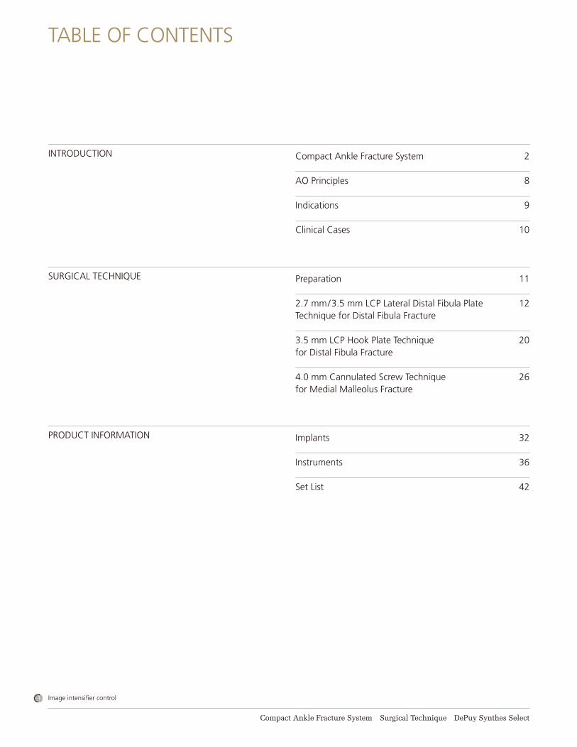
Image intensifier control
Compact Ankle Fracture System Surgical Technique DePuy Synthes Select
INTRODUCTION
SURGICAL TECHNIQUE
PRODUCT INFORMATION
TABLE OF CONTENTS
Compact Ankle Fracture System 2
AO Principles 8
Indications 9
Clinical Cases 10
Preparation 11
2.7 mm/3.5 mm LCP Lateral Distal Fibula Plate 12 Technique for Distal Fibula Fracture
3.5 mm LCP Hook Plate Technique 20for Distal Fibula Fracture
4.0 mm Cannulated Screw Technique 26for Medial Malleolus Fracture
Implants 32
Instruments 36
Set List 42

CONSOLIDATED ANKLE FRACTURE SOLUTION FOR SURGERY CENTERS
Color-coded layout for instrument identifi cation
Includes general instruments; all instrumentation is grouped by screw size, making it easier for surgical teams to quickly locate related components
Contains precontoured fi bula plates, 1/3 tubular plates, and hook plates enabling surgeons to choose the appropriate option based on the complexity of the fracture
Also contains solid and cannulated screws for syndesmotic repair and medial malleolus fractures
Plates are designed to accomodate various fracture patterns and the patient’s anatomy
Locking and conventional screws allow for appropriate bone fi xation
FLEXIBILITY IN THE OPERATING ROOM
Compact Ankle Fracture System Surgical Technique DePuy Synthes Select 3
DePuy Synthes Select offers surgical device systems designed for use in the most common orthopedic and podiatric procedures performed in Ambulatory Surgery Centers (ASCs). The Select compact systems feature the same high-quality DePuy Synthes products used in hospitals, but combined into consolidated sets to help improve effi ciency for our ASC customers.
The confi guration of the Compact Ankle Fracture System contains general instruments, Locking Compression Plates (LCP®) such as fi bula plates, 1/3 tubular plates, hook plate, as well as screws for syndesmotic repair and medial malleolus fractures. The LCP 1/3 tubular plate is a commonly used implant for a high number of distal fi bula fractures that results in a fi xed-angle construct and obtains fi xation in osteoporotic bone. Additionally the LCP distal fi bula plates are anatomically contoured and offer multiple screw options in the head of the plate.
4 DePuy Synthes Select Compact Ankle Fracture System Surgical Technique
Compact Ankle Fracture System
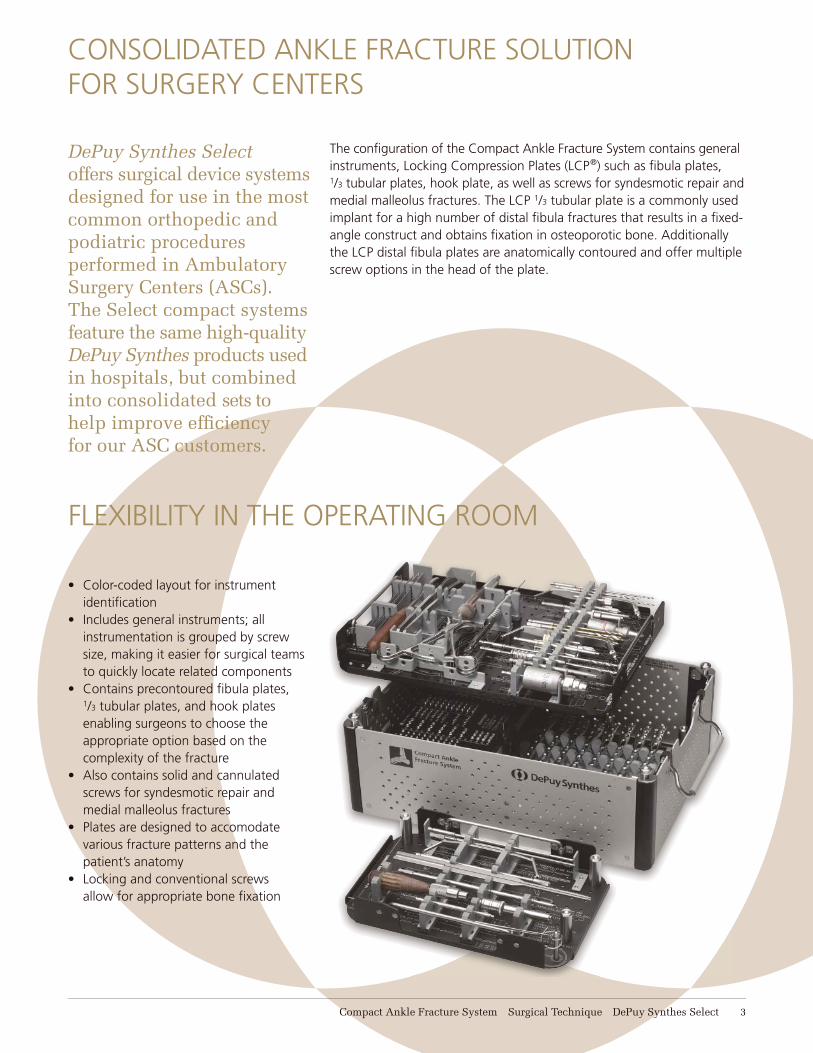
COLOR CODINGA comprehensive color coding system highlights groups of instruments and associated screw sizes/types. Drill bits, drill guides, screwdriver shafts as well as the graphic case trays and screw racks are color-coordinated to facilitate pre-, intra-, and post-operative handling of the sets.
Color Screw size (mm)
Screw type Drill size (mm)Threaded hole= one color band
Drill size (mm)Gliding hole= two color bands
Shaft size
Orange 2.7 Cortex 2.0 2.7 T8
Yellow 3.5/4.0 Cortex/Cancellous 2.5 3.5 2.5 mm Hex
Black 3.5 Locking 2.8 – T15
Gray 4.0 Cannulated 2.7 – 2.5 mm Hex
In addition to the color for each screw size/type a band system distinguishes the drill size for the threaded hole (= one color band) and the gliding hole (= two color bands). The one band/two band principle is also replicated on the drill guides.
Compact Ankle Fracture System Surgical Technique DePuy Synthes Select 5
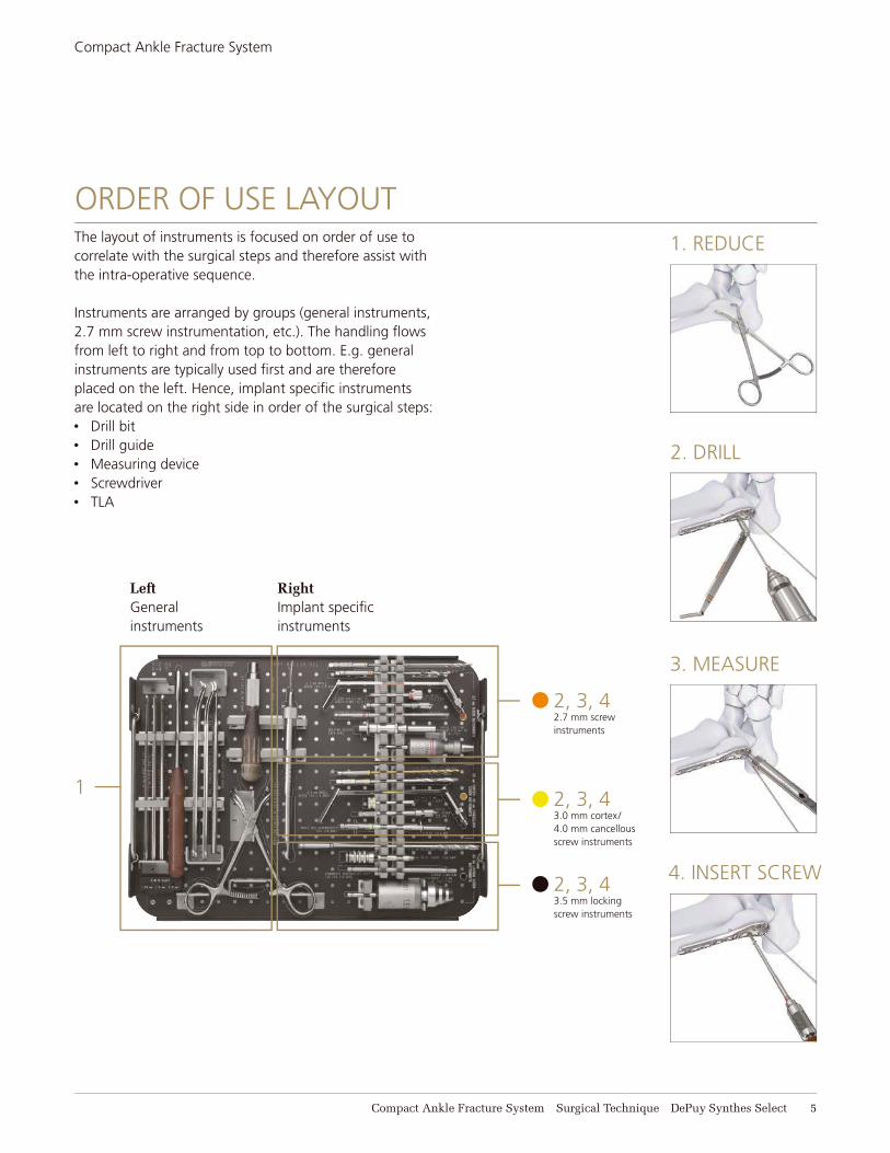
ORDER OF USE LAYOUT
2, 3, 42.7 mm screwinstruments
2, 3, 43.0 mm cortex/4.0 mm cancellous screw instruments
2, 3, 43.5 mm locking screw instruments
RightImplant specifi c instruments
LeftGeneral instruments
The layout of instruments is focused on order of use to correlate with the surgical steps and therefore assist with the intra-operative sequence.
Instruments are arranged by groups (general instruments, 2.7 mm screw instrumentation, etc.). The handling fl ows from left to right and from top to bottom. E.g. general instruments are typically used fi rst and are therefore placed on the left. Hence, implant specifi c instruments are located on the right side in order of the surgical steps:• Drill bit• Drill guide• Measuring device• Screwdriver• TLA
Compact Ankle Fracture System
1
1. REDUCE
3. MEASURE
2. DRILL
4. INSERT SCREW

6 DePuy Synthes Select Compact Ankle Fracture System Surgical Technique
Compact Ankle Fracture System
IMPLANTS
• Anatomically contoured distal fi bula plates
• Multiple screw options in the head of plate
• Locking screws offer a fi xed-angle construct and obtain fi xation in osteoporotic bone
• Coaxial screw holes help minimize screw head prominence and create a low profi le construct
• Allows technique of clamp reduction, followed by independent lag screw, and neutralization plate placement in typical spiral fracture patterns
• For valgus failure fi bular fractures with comminution and for bridge plating of comminuted fractures
• Plate can be contoured to patient anatomy
• Locking screws offer a fi xed-angle construct and obtain fi xation in osteoporotic bone
• Available with 3–10 holes (33 mm–117 mm lengths) and 12 holes (141 mm)
• Plate contains only locking holes, that accept 3.5 mm locking screws, 3.5 mm cortex screws, and 2.7 mm cortex screws
2.7 MM/3.5 MM LCP LATERAL DISTAL FIBULA PLATE
LCP ONE-THIRD TUBULAR PLATE
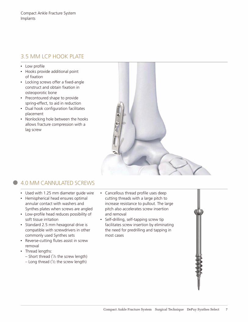
4.0 MM CANNULATED SCREWS
Compact Ankle Fracture System Surgical Technique DePuy Synthes Select 7
Compact Ankle Fracture SystemImplants
• Low profi le• Hooks provide additional point
of fi xation• Locking screws offer a fi xed-angle
construct and obtain fi xation in osteoporotic bone
• Precontoured shape to provide spring-effect, to aid in reduction
• Dual hook confi guration facilitates placement
• Nonlocking hole between the hooks allows fracture compression with a lag screw
• Used with 1.25 mm diameter guide wire• Hemispherical head ensures optimal
annular contact with washers and Synthes plates when screws are angled
• Low-profi le head reduces possibility of soft tissue irritation
• Standard 2.5 mm hexagonal drive is compatible with screwdrivers in other commonly used Synthes sets
• Reverse-cutting fl utes assist in screw removal
• Thread lengths: – Short thread (1/3 the screw length) – Long thread (1/2 the screw length)
• Cancellous thread profi le uses deep cutting threads with a large pitch to increase resistance to pullout. The large pitch also accelerates screw insertion and removal
• Self-drilling, self-tapping screw tip facilitates screw insertion by eliminating the need for predrilling and tapping in most cases
3.5 MM LCP HOOK PLATE
8 DePuy Synthes Select Compact Ankle Fracture System Surgical Technique
In 1958, the AO formulated four basic principles, which have become the guidelines for internal fixation.1 They are:
Anatomic reductionFracture reduction and fixation to restore anatomical relationships.
Stable fixationStability by fixation or splintage, as the personality of the fracture and the injury requires.
Preservation of blood supplyPreservation of the blood supply to soft tissue and bone by careful handling.
Early, active mobilizationEarly, active mobilization of the part and patient.
AO PRINCIPLES
1 Müller ME, M Allgöwer, R Schneider, H Willenegger. Manual of Internal Fixation. 3rd ed. Berlin Heidelberg New York: Springer. 1991.
Compact Ankle Fracture System Surgical Technique DePuy Synthes Select 9
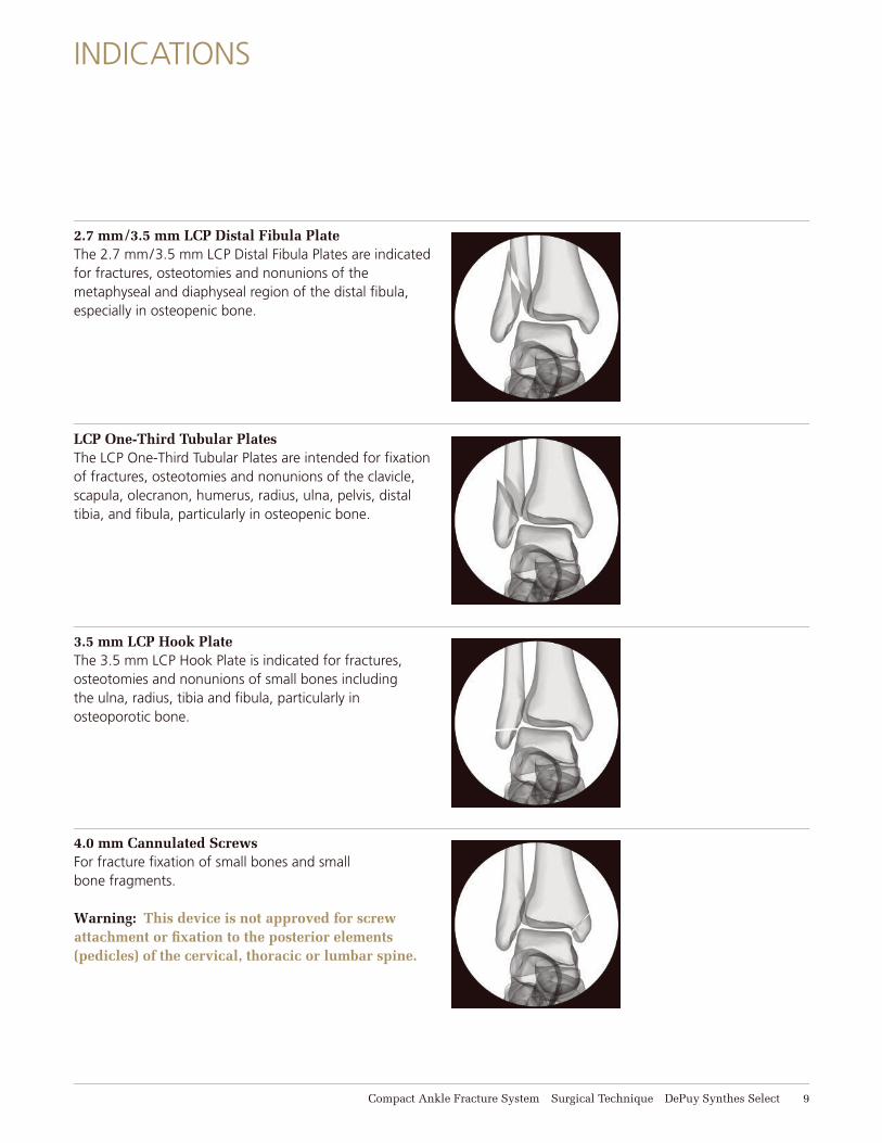
2.7 mm/3.5 mm LCP Distal Fibula PlateThe 2.7 mm/3.5 mm LCP Distal Fibula Plates are indicated for fractures, osteotomies and nonunions of the metaphyseal and diaphyseal region of the distal fi bula, especially in osteopenic bone.
INDICATIONS
4.0 mm Cannulated ScrewsFor fracture fi xation of small bones and small bone fragments.
Warning: This device is not approved for screw attachment or fi xation to the posterior elements (pedicles) of the cervical, thoracic or lumbar spine.
LCP One-Third Tubular PlatesThe LCP One-Third Tubular Plates are intended for fi xation of fractures, osteotomies and nonunions of the clavicle, scapula, olecranon, humerus, radius, ulna, pelvis, distal tibia, and fi bula, particularly in osteopenic bone.
3.5 mm LCP Hook PlateThe 3.5 mm LCP Hook Plate is indicated for fractures, osteotomies and nonunions of small bones including the ulna, radius, tibia and fi bula, particularly in osteoporotic bone.
10 DePuy Synthes Select Compact Ankle Fracture System Surgical Technique
CLINICAL CASES
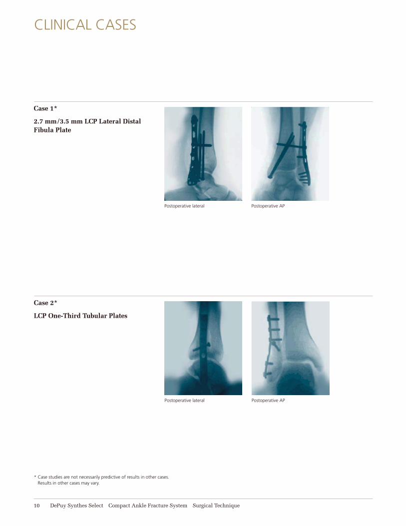
Case 1*
2.7 mm/3.5 mm LCP Lateral Distal Fibula Plate
Postoperative lateral Postoperative AP
Case 2*
LCP One-Third Tubular Plates
Postoperative lateral Postoperative AP
* Case studies are not necessarily predictive of results in other cases. Results in other cases may vary.
Compact Ankle Fracture System Surgical Technique DePuy Synthes Select 11
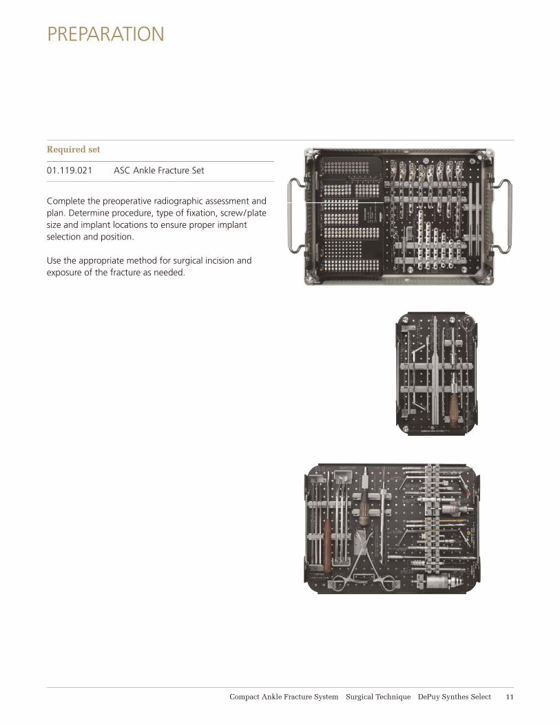
Required set
01.119.021 ASC Ankle Fracture Set
Complete the preoperative radiographic assessment and plan. Determine procedure, type of fi xation, screw/plate size and implant locations to ensure proper implant selection and position.
Use the appropriate method for surgical incision and exposure of the fracture as needed.
PREPARATION
12 DePuy Synthes Select Compact Ankle Fracture System Surgical Technique
2.7 MM/3.5 MM LCP LATERAL DISTAL FIBULA PLATE TECHNIQUE FOR DISTAL FIBULA FRACTURE
The techniques for implanting the lateral distal fi bula plate and one-third tubular plate are similar. The following describes implantation of a lateral distal fi bula plate.
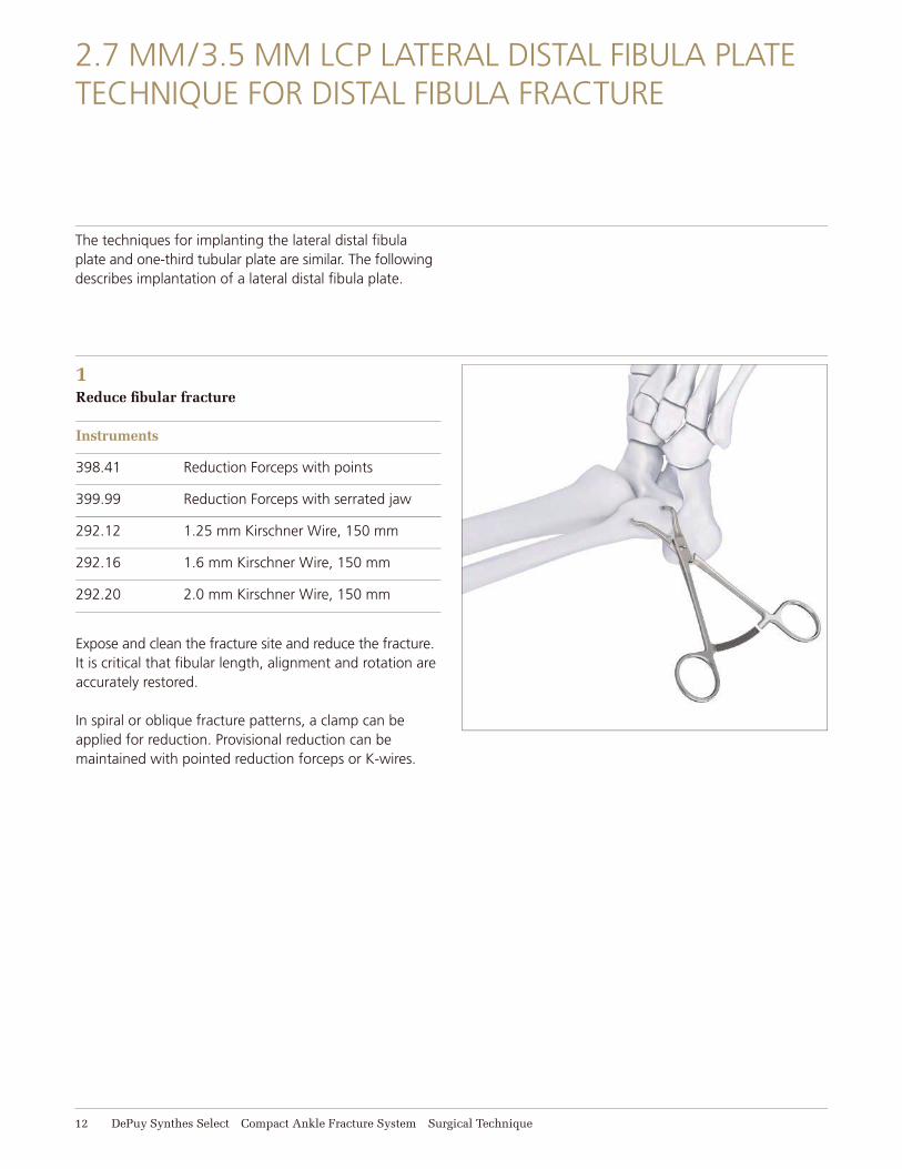
1Reduce fi bular fracture
Instruments
398.41 Reduction Forceps with points
399.99 Reduction Forceps with serrated jaw
292.12 1.25 mm Kirschner Wire, 150 mm
292.16 1.6 mm Kirschner Wire, 150 mm
292.20 2.0 mm Kirschner Wire, 150 mm
Expose and clean the fracture site and reduce the fracture. It is critical that fi bular length, alignment and rotation are accurately restored.
In spiral or oblique fracture patterns, a clamp can be applied for reduction. Provisional reduction can be maintained with pointed reduction forceps or K-wires.
Compact Ankle Fracture System Surgical Technique DePuy Synthes Select 13
2.7 mm/3.5 mm LCP Lateral Distal Fibula Plate Technique for Distal Fibula Fracture
1. Reduce fibular fracture continued
Alternatively, in some fracture patterns, the plate can be used to assist with and guide the reduction. This may be especially important in comminuted fractures where a bridging technique is used.
Technique tip: Application of an external fixator or distractor may facilitate obtaining fibular length, fracture reduction and visualization of the distal tibiofibular joint.
Confirm the reduction with image intensification. Temporary reduction can be obtained with clamps, multiple Kirschner wires, or independent lag screws if the fracture pattern allows. K-wires can be placed through the distal end of the plate to assist with temporary maintenance of the reduction and for plate placement. Options for maintaining the reduction depend on the fracture configuration and include:• Independent lag screws• Lag screws through the plate• Locking screws through the plate
Locking screws do not provide interfragmentary compression; compression must be achieved with standard lag screws or by using the plate itself to compress the fracture. The fracture must be reduced and compressed before fixation of the LCP distal fibula plate with locking screws in simple fracture configurations. If a bridge plate technique is planned, the implant can be secured proximally and distally using locking screws, if the fibular length, alignment and rotation are correct.
14 DePuy Synthes Select Compact Ankle Fracture System Surgical Technique
2.7 mm/3.5 mm LCP Lateral Distal Fibula Plate Technique for Distal Fibula Fracture
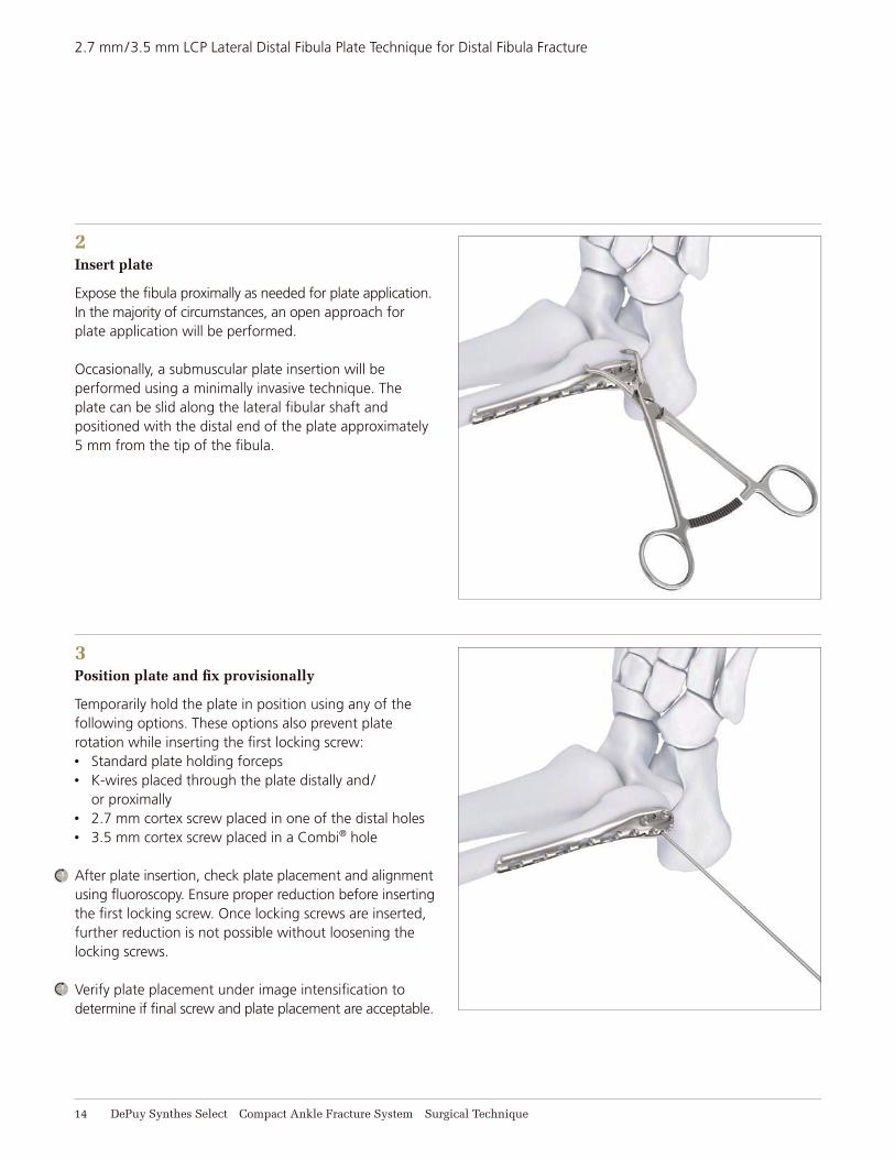
2Insert plate
Expose the fi bula proximally as needed for plate application. In the majority of circumstances, an open approach for plate application will be performed.
Occasionally, a submuscular plate insertion will be performed using a minimally invasive technique. The plate can be slid along the lateral fi bular shaft and positioned with the distal end of the plate approximately 5 mm from the tip of the fi bula.
3Position plate and fi x provisionally
Temporarily hold the plate in position using any of the following options. These options also prevent plate rotation while inserting the fi rst locking screw:• Standard plate holding forceps• K-wires placed through the plate distally and/
or proximally• 2.7 mm cortex screw placed in one of the distal holes• 3.5 mm cortex screw placed in a Combi® hole
After plate insertion, check plate placement and alignment using fl uoroscopy. Ensure proper reduction before inserting the fi rst locking screw. Once locking screws are inserted, further reduction is not possible without loosening the locking screws.
Verify plate placement under image intensifi cation to determine if fi nal screw and plate placement are acceptable.
Compact Ankle Fracture System Surgical Technique DePuy Synthes Select 15
2.7 mm/3.5 mm LCP Lateral Distal Fibula Plate Technique for Distal Fibula Fracture
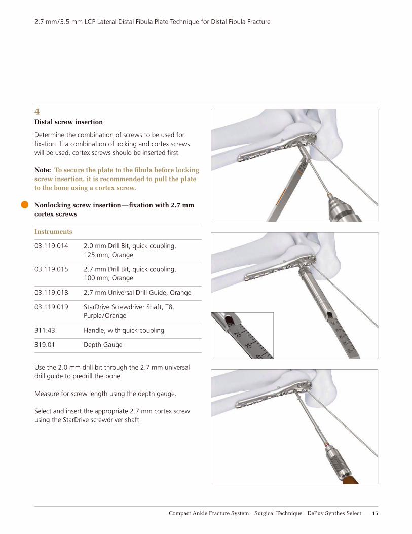
4Distal screw insertion
Determine the combination of screws to be used for fi xation. If a combination of locking and cortex screws will be used, cortex screws should be inserted fi rst.
Note: To secure the plate to the fi bula before lockingscrew insertion, it is recommended to pull the plateto the bone using a cortex screw.
Nonlocking screw insertion—fi xation with 2.7 mm cortex screws
Instruments
03.119.014 2.0 mm Drill Bit, quick coupling, 125 mm, Orange
03.119.015 2.7 mm Drill Bit, quick coupling, 100 mm, Orange
03.119.018 2.7 mm Universal Drill Guide, Orange
03.119.019 StarDrive Screwdriver Shaft, T8, Purple/Orange
311.43 Handle, with quick coupling
319.01 Depth Gauge
Use the 2.0 mm drill bit through the 2.7 mm universal drill guide to predrill the bone.
Measure for screw length using the depth gauge.
Select and insert the appropriate 2.7 mm cortex screw using the StarDrive screwdriver shaft.
16 DePuy Synthes Select Compact Ankle Fracture System Surgical Technique
2.7 mm/3.5 mm LCP Lateral Distal Fibula Plate Technique for Distal Fibula Fracture
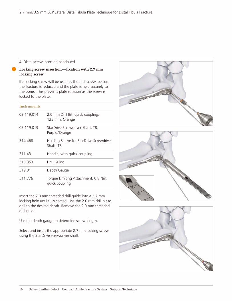
4. Distal screw insertion continued
Locking screw insertion—fi xation with 2.7 mm locking screw
If a locking screw will be used as the fi rst screw, be sure the fracture is reduced and the plate is held securely to the bone. This prevents plate rotation as the screw is locked to the plate.
Instruments
03.119.014 2.0 mm Drill Bit, quick coupling, 125 mm, Orange
03.119.019 StarDrive Screwdriver Shaft, T8, Purple/Orange
314.468 Holding Sleeve for StarDrive Screwdriver Shaft, T8
311.43 Handle, with quick coupling
313.353 Drill Guide
319.01 Depth Gauge
511.776 Torque Limiting Attachment, 0.8 Nm, quick coupling
Insert the 2.0 mm threaded drill guide into a 2.7 mm locking hole until fully seated. Use the 2.0 mm drill bit to drill to the desired depth. Remove the 2.0 mm threaded drill guide.
Use the depth gauge to determine screw length.
Select and insert the appropriate 2.7 mm locking screw using the StarDrive screwdriver shaft.
Compact Ankle Fracture System Surgical Technique DePuy Synthes Select 17
2.7 mm/3.5 mm LCP Lateral Distal Fibula Plate Technique for Distal Fibula Fracture
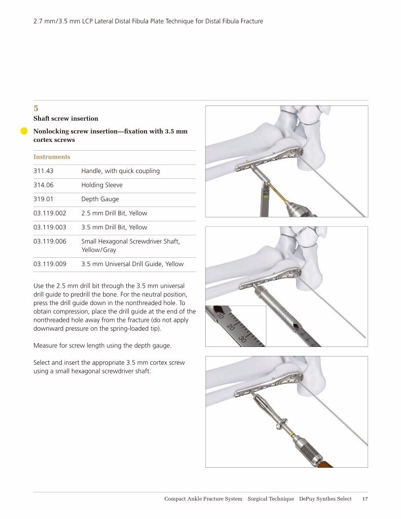
5Shaft screw insertion
Nonlocking screw insertion—fi xation with 3.5 mm cortex screws
Instruments
311.43 Handle, with quick coupling
314.06 Holding Sleeve
319.01 Depth Gauge
03.119.002 2.5 mm Drill Bit, Yellow
03.119.003 3.5 mm Drill Bit, Yellow
03.119.006 Small Hexagonal Screwdriver Shaft, Yellow/Gray
03.119.009 3.5 mm Universal Drill Guide, Yellow
Use the 2.5 mm drill bit through the 3.5 mm universal drill guide to predrill the bone. For the neutral position, press the drill guide down in the nonthreaded hole. To obtain compression, place the drill guide at the end of the nonthreaded hole away from the fracture (do not apply downward pressure on the spring-loaded tip).
Measure for screw length using the depth gauge.
Select and insert the appropriate 3.5 mm cortex screw using a small hexagonal screwdriver shaft.
18 DePuy Synthes Select Compact Ankle Fracture System Surgical Technique
2.7 mm/3.5 mm LCP Lateral Distal Fibula Plate Technique for Distal Fibula Fracture
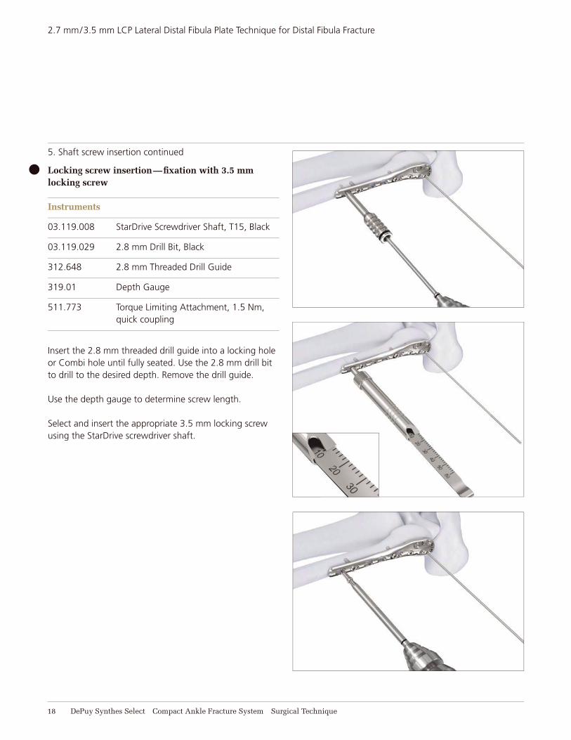
5. Shaft screw insertion continued
Locking screw insertion—fi xation with 3.5 mm locking screw
Instruments
03.119.008 StarDrive Screwdriver Shaft, T15, Black
03.119.029 2.8 mm Drill Bit, Black
312.648 2.8 mm Threaded Drill Guide
319.01 Depth Gauge
511.773 Torque Limiting Attachment, 1.5 Nm, quick coupling
Insert the 2.8 mm threaded drill guide into a locking hole or Combi hole until fully seated. Use the 2.8 mm drill bit to drill to the desired depth. Remove the drill guide.
Use the depth gauge to determine screw length.
Select and insert the appropriate 3.5 mm locking screw using the StarDrive screwdriver shaft.
Compact Ankle Fracture System Surgical Technique DePuy Synthes Select 19
2.7 mm/3.5 mm LCP Lateral Distal Fibula Plate Technique for Distal Fibula Fracture
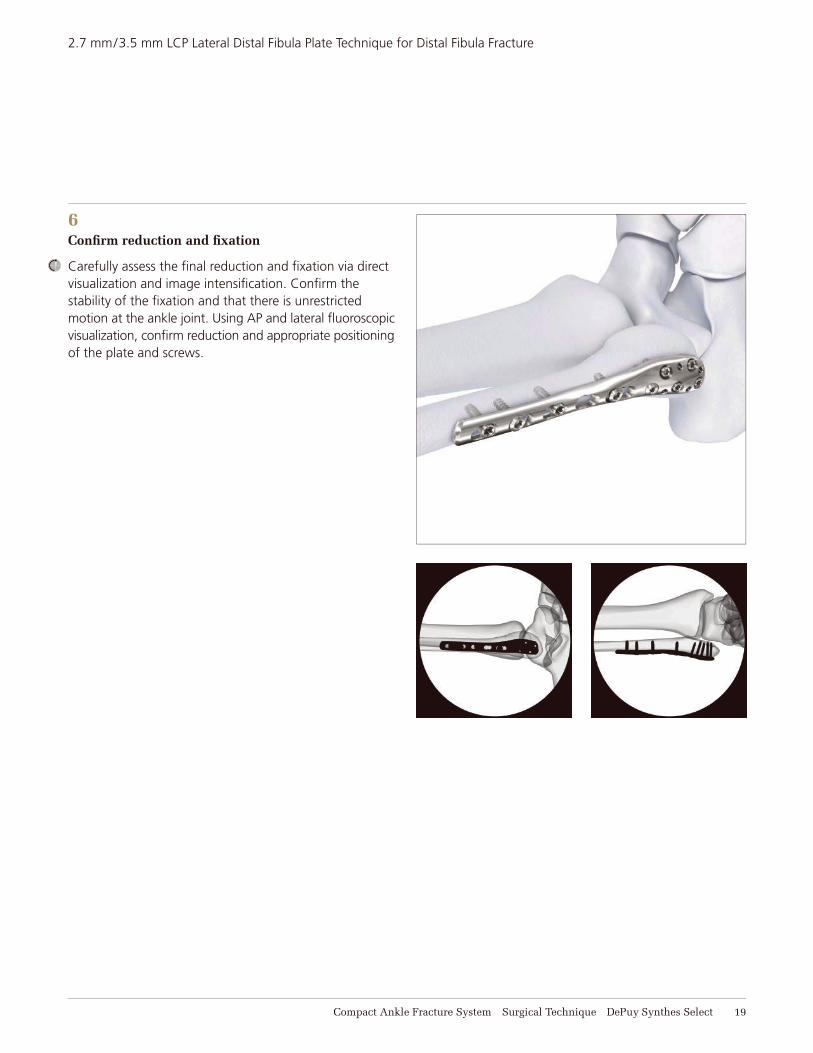
6Confi rm reduction and fi xation
Carefully assess the fi nal reduction and fi xation via direct visualization and image intensifi cation. Confi rm the stability of the fi xation and that there is unrestricted motion at the ankle joint. Using AP and lateral fl uoroscopic visualization, confi rm reduction and appropriate positioning of the plate and screws.
20 DePuy Synthes Select Compact Ankle Fracture System Surgical Technique
3.5 MM LCP HOOK PLATE TECHNIQUE FOR DISTAL FIBULA FRACTURE
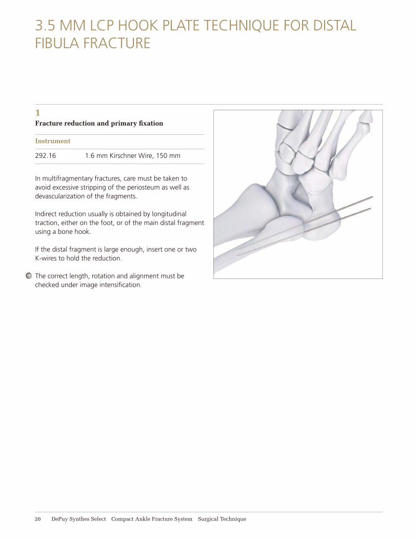
1Fracture reduction and primary fi xation
Instrument
292.16 1.6 mm Kirschner Wire, 150 mm
In multifragmentary fractures, care must be taken to avoid excessive stripping of the periosteum as well as devascularization of the fragments.
Indirect reduction usually is obtained by longitudinal traction, either on the foot, or of the main distal fragment using a bone hook.
If the distal fragment is large enough, insert one or two K-wires to hold the reduction.
The correct length, rotation and alignment must be checked under image intensifi cation.
Compact Ankle Fracture System Surgical Technique DePuy Synthes Select 21
3.5 mm LCP Hook Plate Technique for Distal Fibula Fracture
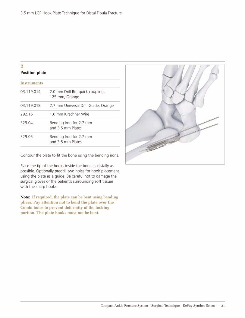
2Position plate
Instruments
03.119.014 2.0 mm Drill Bit, quick coupling, 125 mm, Orange
03.119.018 2.7 mm Universal Drill Guide, Orange
292.16 1.6 mm Kirschner Wire
329.04 Bending Iron for 2.7 mm and 3.5 mm Plates
329.05 Bending Iron for 2.7 mm and 3.5 mm Plates
Contour the plate to fi t the bone using the bending irons.
Place the tip of the hooks inside the bone as distally as possible. Optionally predrill two holes for hook placement using the plate as a guide. Be careful not to damage the surgical gloves or the patient’s surrounding soft tissues with the sharp hooks.
Note: If required, the plate can be bent using bending pliers. Pay attention not to bend the plate over the Combi holes to prevent deformity of the locking portion. The plate hooks must not be bent.
22 DePuy Synthes Select Compact Ankle Fracture System Surgical Technique
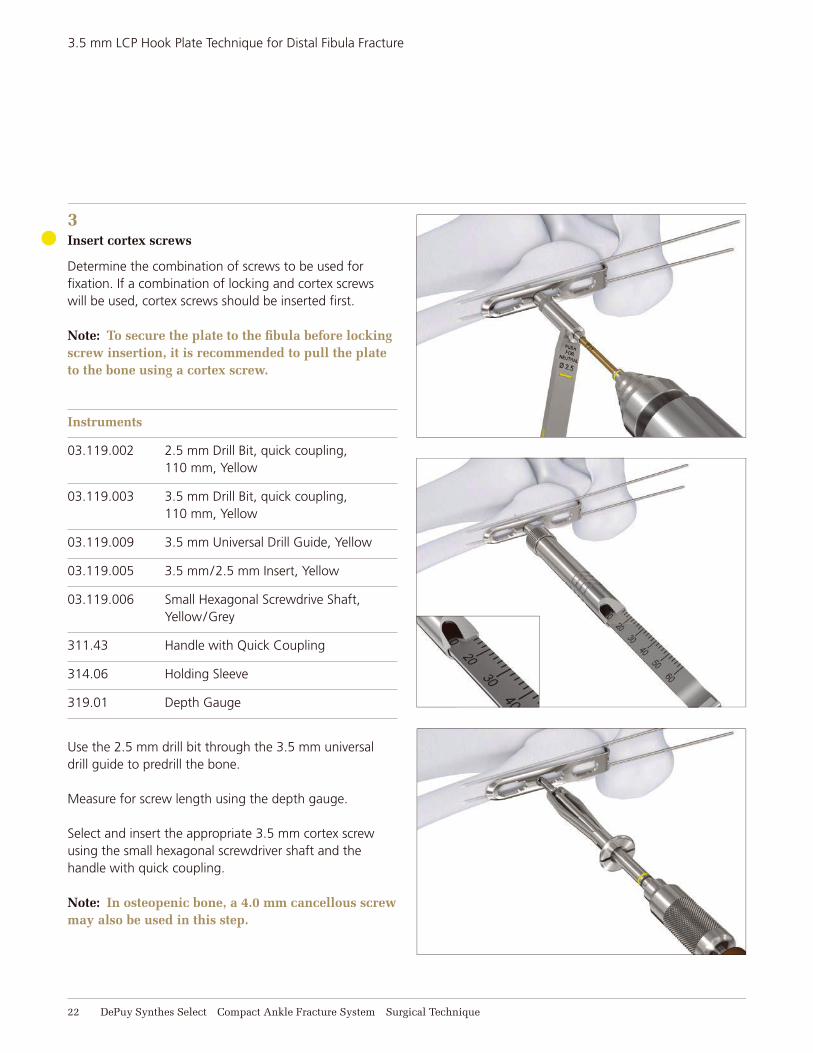
3Insert cortex screws
Determine the combination of screws to be used for fi xation. If a combination of locking and cortex screws will be used, cortex screws should be inserted fi rst.
Note: To secure the plate to the fi bula before lockingscrew insertion, it is recommended to pull the plateto the bone using a cortex screw.
Instruments
03.119.002 2.5 mm Drill Bit, quick coupling, 110 mm, Yellow
03.119.003 3.5 mm Drill Bit, quick coupling, 110 mm, Yellow
03.119.009 3.5 mm Universal Drill Guide, Yellow
03.119.005 3.5 mm/2.5 mm Insert, Yellow
03.119.006 Small Hexagonal Screwdrive Shaft, Yellow/Grey
311.43 Handle with Quick Coupling
314.06 Holding Sleeve
319.01 Depth Gauge
Use the 2.5 mm drill bit through the 3.5 mm universal drill guide to predrill the bone.
Measure for screw length using the depth gauge.
Select and insert the appropriate 3.5 mm cortex screw using the small hexagonal screwdriver shaft and the handle with quick coupling.
Note: In osteopenic bone, a 4.0 mm cancellous screwmay also be used in this step.
3.5 mm LCP Hook Plate Technique for Distal Fibula Fracture
Compact Ankle Fracture System Surgical Technique DePuy Synthes Select 23
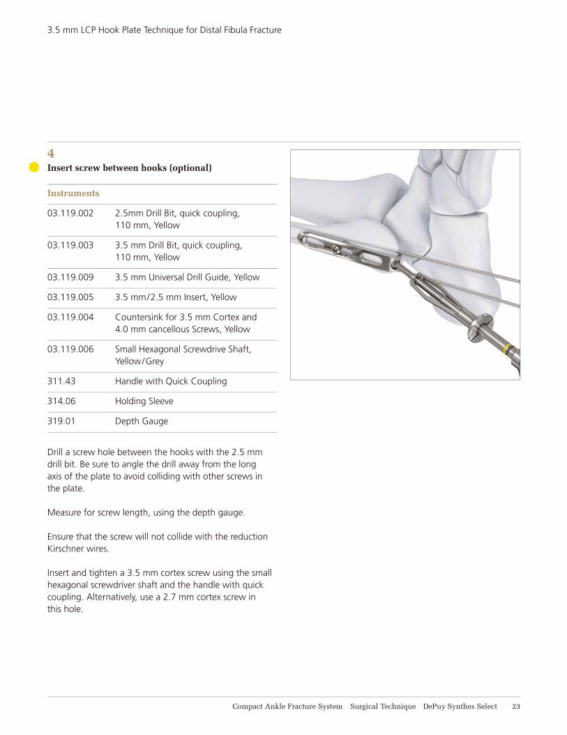
4Insert screw between hooks (optional)
Instruments
03.119.002 2.5mm Drill Bit, quick coupling, 110 mm, Yellow
03.119.003 3.5 mm Drill Bit, quick coupling, 110 mm, Yellow
03.119.009 3.5 mm Universal Drill Guide, Yellow
03.119.005 3.5 mm/2.5 mm Insert, Yellow
03.119.004 Countersink for 3.5 mm Cortex and 4.0 mm cancellous Screws, Yellow
03.119.006 Small Hexagonal Screwdrive Shaft, Yellow/Grey
311.43 Handle with Quick Coupling
314.06 Holding Sleeve
319.01 Depth Gauge
Drill a screw hole between the hooks with the 2.5 mm drill bit. Be sure to angle the drill away from the long axis of the plate to avoid colliding with other screws in the plate.
Measure for screw length, using the depth gauge.
Ensure that the screw will not collide with the reduction Kirschner wires.
Insert and tighten a 3.5 mm cortex screw using the small hexagonal screwdriver shaft and the handle with quick coupling. Alternatively, use a 2.7 mm cortex screw in this hole.
3.5 mm LCP Hook Plate Technique for Distal Fibula Fracture
24 DePuy Synthes Select Compact Ankle Fracture System Surgical Technique
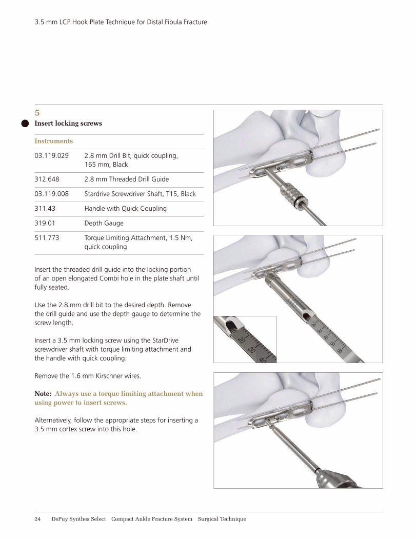
5Insert locking screws
Instruments
03.119.029 2.8 mm Drill Bit, quick coupling, 165 mm, Black
312.648 2.8 mm Threaded Drill Guide
03.119.008 Stardrive Screwdriver Shaft, T15, Black
311.43 Handle with Quick Coupling
319.01 Depth Gauge
511.773 Torque Limiting Attachment, 1.5 Nm, quick coupling
Insert the threaded drill guide into the locking portion of an open elongated Combi hole in the plate shaft until fully seated.
Use the 2.8 mm drill bit to the desired depth. Remove the drill guide and use the depth gauge to determine the screw length.
Insert a 3.5 mm locking screw using the StarDrive screwdriver shaft with torque limiting attachment and the handle with quick coupling.
Remove the 1.6 mm Kirschner wires.
Note: Always use a torque limiting attachment whenusing power to insert screws.
Alternatively, follow the appropriate steps for inserting a 3.5 mm cortex screw into this hole.
3.5 mm LCP Hook Plate Technique for Distal Fibula Fracture
Compact Ankle Fracture System Surgical Technique DePuy Synthes Select 25
3.5 mm LCP Hook Plate Technique for Distal Fibula Fracture
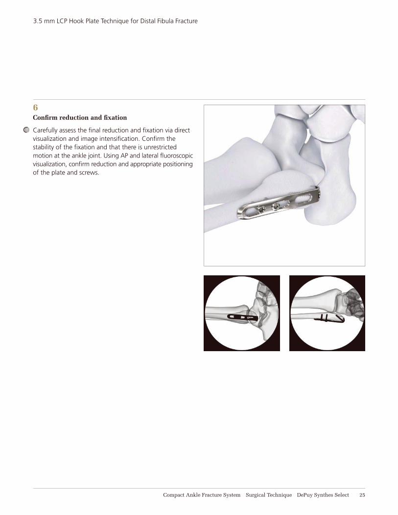
6Confi rm reduction and fi xation
Carefully assess the fi nal reduction and fi xation via direct visualization and image intensifi cation. Confi rm the stability of the fi xation and that there is unrestricted motion at the ankle joint. Using AP and lateral fl uoroscopic visualization, confi rm reduction and appropriate positioning of the plate and screws.

26 DePuy Synthes Select Compact Ankle Fracture System Surgical Technique
4.0 MM CANNULATED SCREW TECHNIQUE FOR MEDIAL MALLEOLUS FRACTURE
1Reduction
Instrument
398.41 Reduction Forceps with Points, broad
Reduce the fracture anatomically with the use of small pointed reduction forceps, taking care with the soft tissues.
Do not strip the periosteum more than necessary.
Compact Ankle Fracture System Surgical Technique DePuy Synthes Select 27
4.0 mm Cannulated Screw Technique for Medial Malleolus Fracture
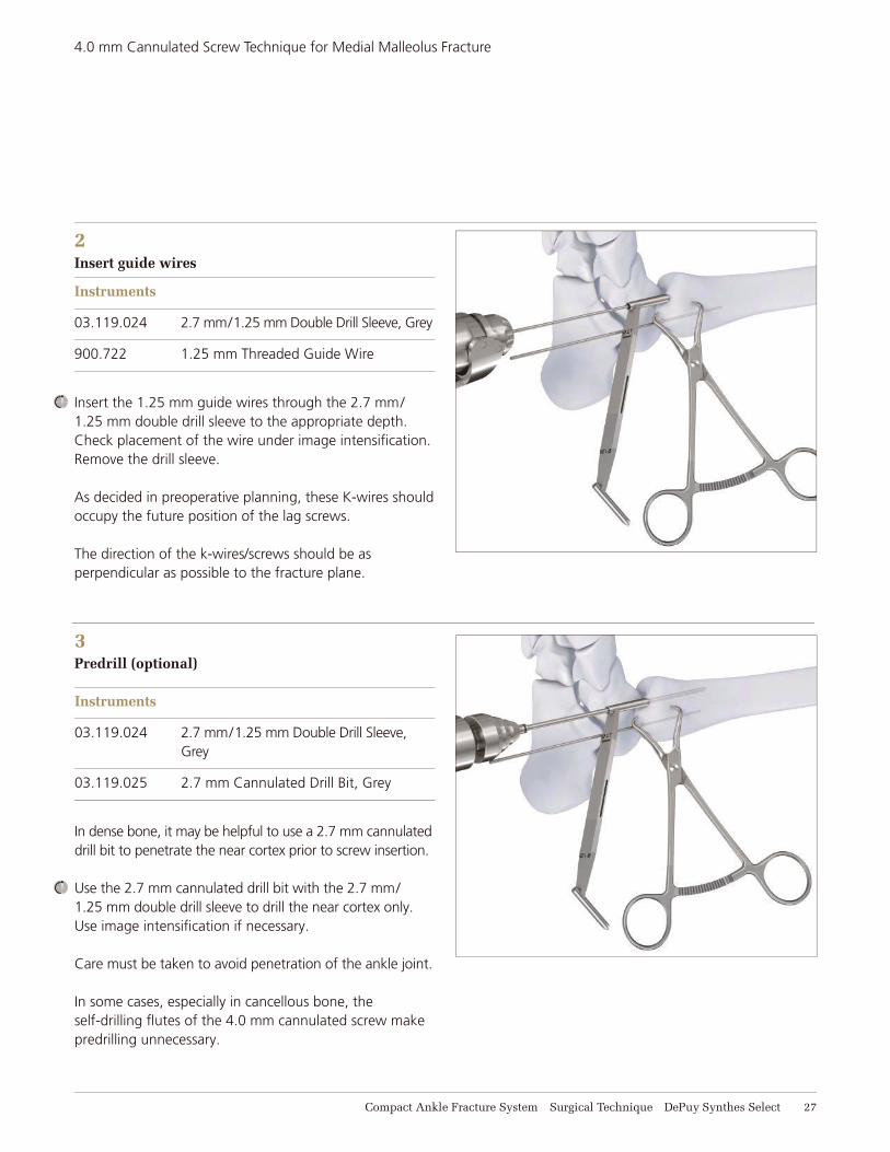
2Insert guide wires
Instruments
03.119.024 2.7 mm/1.25 mm Double Drill Sleeve, Grey
900.722 1.25 mm Threaded Guide Wire
Insert the 1.25 mm guide wires through the 2.7 mm/1.25 mm double drill sleeve to the appropriate depth. Check placement of the wire under image intensifi cation. Remove the drill sleeve.
As decided in preoperative planning, these K-wires should occupy the future position of the lag screws.
The direction of the k-wires/screws should be as perpendicular as possible to the fracture plane.
3Predrill (optional)
Instruments
03.119.024 2.7 mm/1.25 mm Double Drill Sleeve, Grey
03.119.025 2.7 mm Cannulated Drill Bit, Grey
In dense bone, it may be helpful to use a 2.7 mm cannulated drill bit to penetrate the near cortex prior to screw insertion.
Use the 2.7 mm cannulated drill bit with the 2.7 mm/1.25 mm double drill sleeve to drill the near cortex only. Use image intensifi cation if necessary.
Care must be taken to avoid penetration of the ankle joint.
In some cases, especially in cancellous bone, the self-drilling fl utes of the 4.0 mm cannulated screw make predrilling unnecessary.
28 DePuy Synthes Select Compact Ankle Fracture System Surgical Technique
4.0 mm Cannulated Screw Technique for Medial Malleolus Fracture
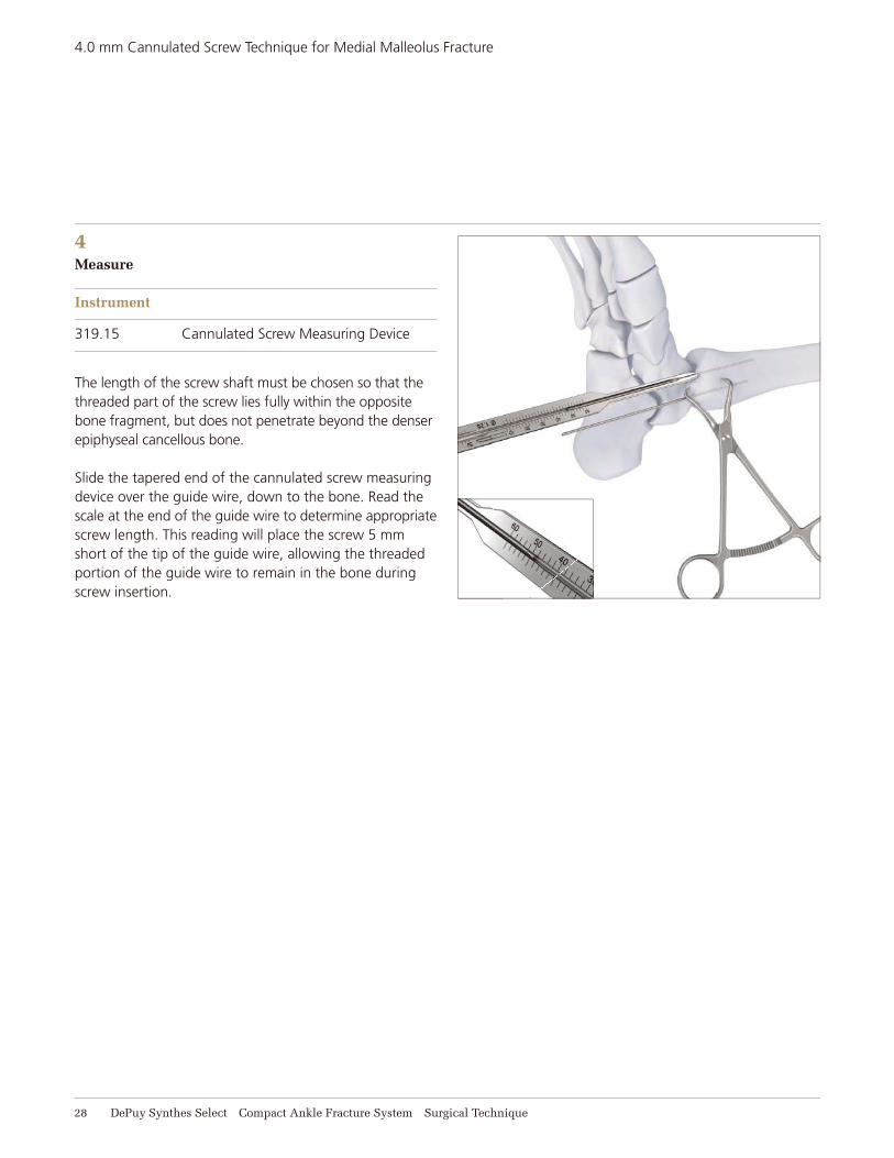
4Measure
Instrument
319.15 Cannulated Screw Measuring Device
The length of the screw shaft must be chosen so that the threaded part of the screw lies fully within the opposite bone fragment, but does not penetrate beyond the denser epiphyseal cancellous bone.
Slide the tapered end of the cannulated screw measuring device over the guide wire, down to the bone. Read the scale at the end of the guide wire to determine appropriate screw length. This reading will place the screw 5 mm short of the tip of the guide wire, allowing the threaded portion of the guide wire to remain in the bone during screw insertion.
Compact Ankle Fracture System Surgical Technique DePuy Synthes Select 29
4.0 mm Cannulated Screw Technique for Medial Malleolus Fracture
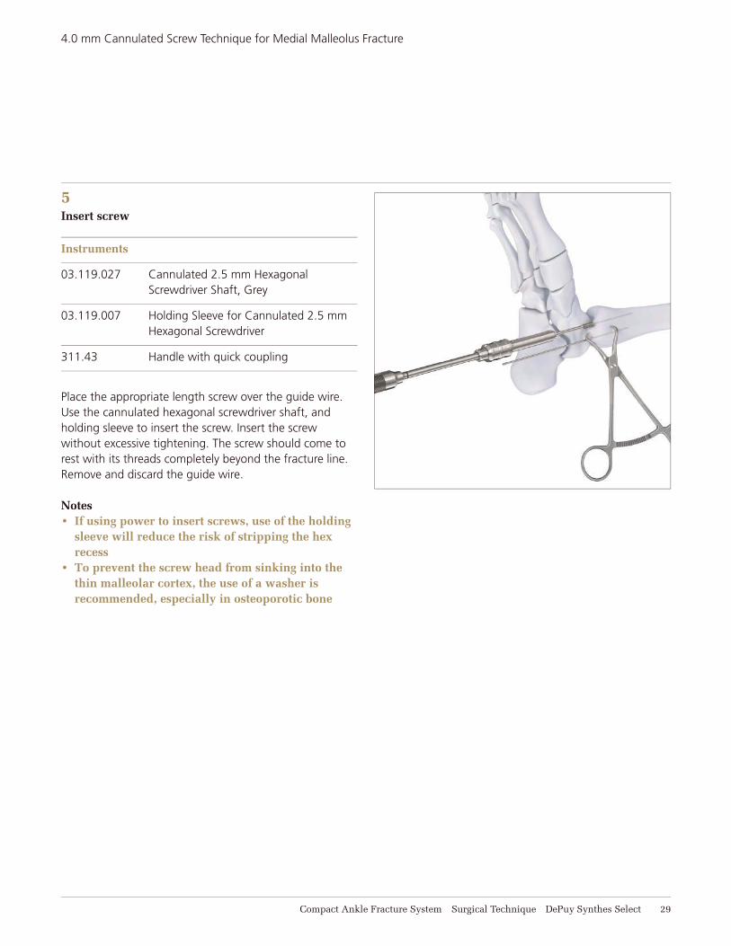
5Insert screw
Instruments
03.119.027 Cannulated 2.5 mm Hexagonal Screwdriver Shaft, Grey
03.119.007 Holding Sleeve for Cannulated 2.5 mm Hexagonal Screwdriver
311.43 Handle with quick coupling
Place the appropriate length screw over the guide wire. Use the cannulated hexagonal screwdriver shaft, and holding sleeve to insert the screw. Insert the screw without excessive tightening. The screw should come to rest with its threads completely beyond the fracture line. Remove and discard the guide wire.
Notes If using power to insert screws, use of the holding sleeve will reduce the risk of stripping the hex recess
To prevent the screw head from sinking into the thin malleolar cortex, the use of a washer is recommended, especially in osteoporotic bone
30 DePuy Synthes Select Compact Ankle Fracture System Surgical Technique
4.0 mm Cannulated Screw Technique for Medial Malleolus Fracture
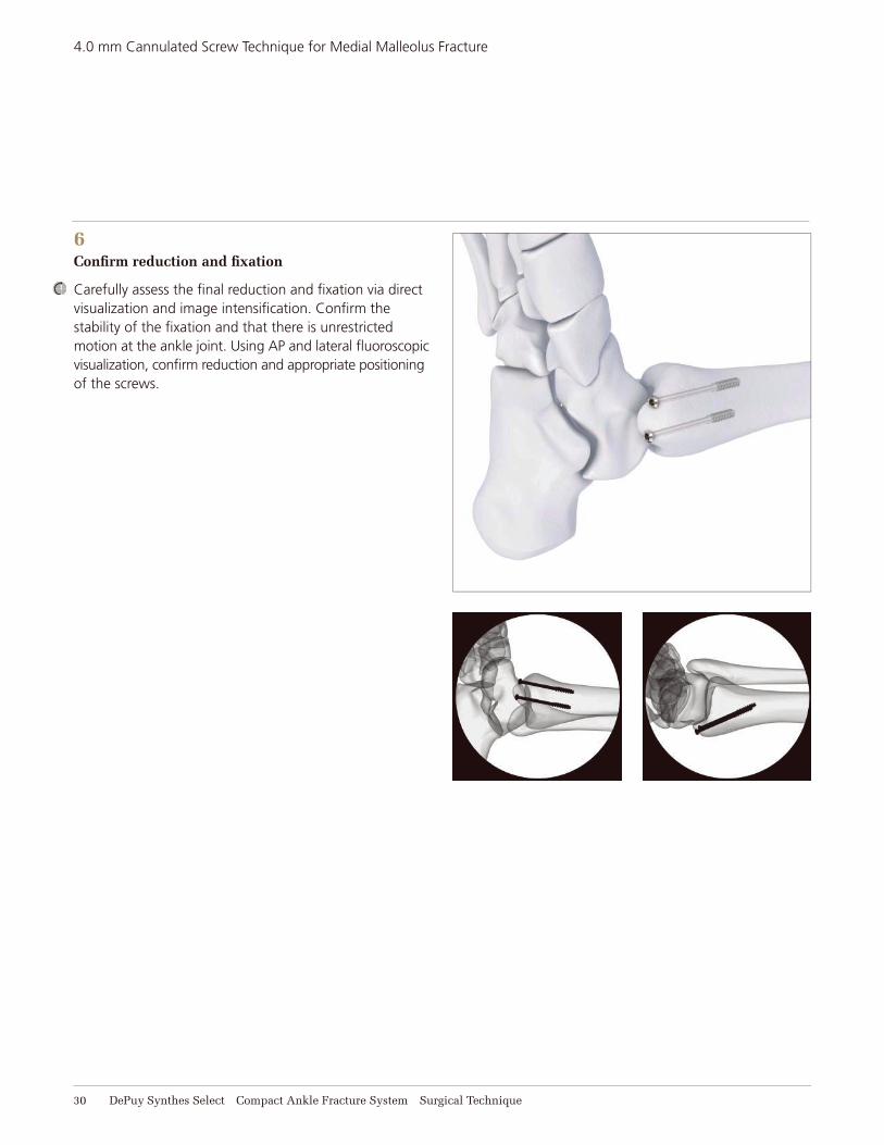
6Confi rm reduction and fi xation
Carefully assess the fi nal reduction and fi xation via direct visualization and image intensifi cation. Confi rm the stability of the fi xation and that there is unrestricted motion at the ankle joint. Using AP and lateral fl uoroscopic visualization, confi rm reduction and appropriate positioning of the screws.
Compact Ankle Fracture System Surgical Technique DePuy Synthes Select 31
4.0 mm Cannulated Screw Technique for Medial Malleolus Fracture
7Cleaning cannulations
Instruments
319.25 1.35 mm Cleaning Brush
319.38 1.25 mm Cleaning Sylet
Note: Cleaning the cannulation in each instrument is imperative for proper function and component life.
Instruments should be cleared intraoperatively with the cleaning stylet to prevent accumulation of debris in the cannulation and potential binding of the instruments about the guide wire. Instruments should be cleaned postoperatively with both the stylet and cleaning brush.
32 DePuy Synthes Select Compact Ankle Fracture System Surgical Technique
IMPLANTS
Screws are available in:1. 316L stainless steel2. commercially pure (CP) titanium3. titanium alloy (Ti-6AI-7Nb)
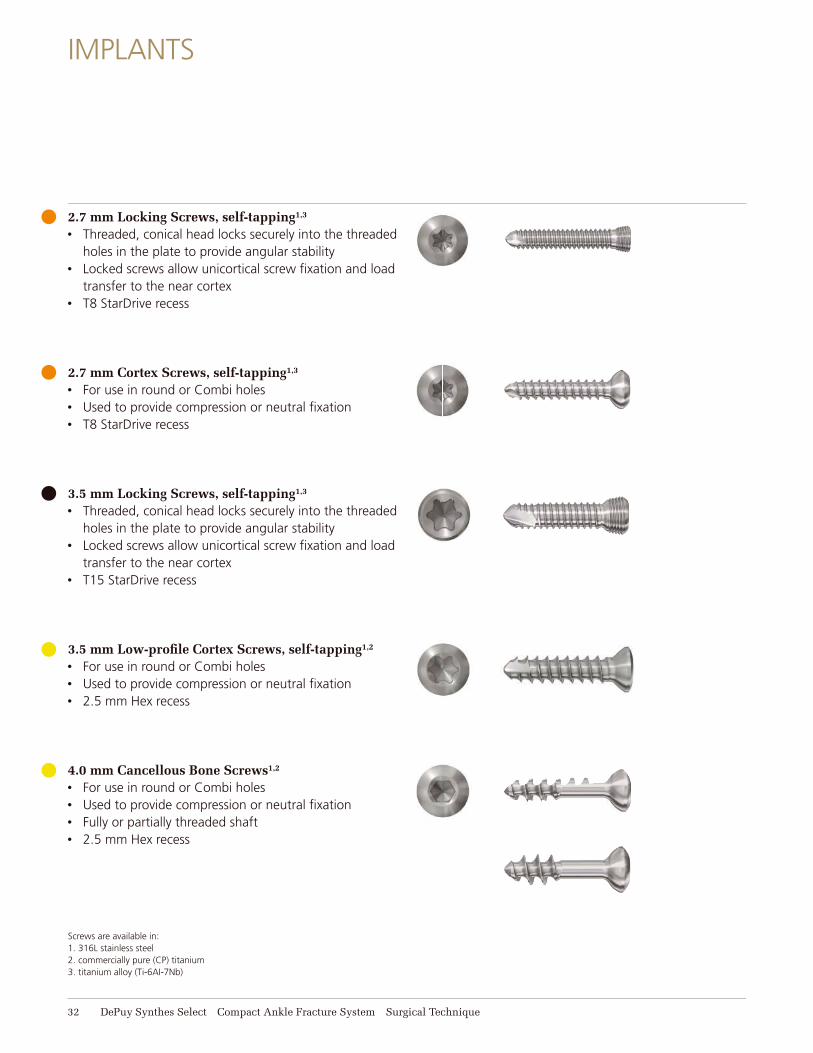
2.7 mm Locking Screws, self-tapping1,3
• Threaded, conical head locks securely into the threaded holes in the plate to provide angular stability
• Locked screws allow unicortical screw fi xation and load transfer to the near cortex
• T8 StarDrive recess
2.7 mm Cortex Screws, self-tapping1,3
• For use in round or Combi holes• Used to provide compression or neutral fi xation• T8 StarDrive recess
3.5 mm Locking Screws, self-tapping1,3 • Threaded, conical head locks securely into the threaded
holes in the plate to provide angular stability• Locked screws allow unicortical screw fi xation and load
transfer to the near cortex• T15 StarDrive recess
3.5 mm Low-profi le Cortex Screws, self-tapping1,2
• For use in round or Combi holes• Used to provide compression or neutral fi xation• 2.5 mm Hex recess
4.0 mm Cancellous Bone Screws1,2 • For use in round or Combi holes• Used to provide compression or neutral fi xation• Fully or partially threaded shaft• 2.5 mm Hex recess

Compact Ankle Fracture System Surgical Technique DePuy Synthes Select 33
Implants
4.0 mm Cannulated Screws, short thread1,3
• Cannulated shaft accepts 1.25 mm diameter guide wires
• Thread length = 1/3 screw length• 2.5 mm Hex recess
Washer, 7.0 mm1,3
• To prevent screw head from sinking into osteoporotic bone
Screws are available in:1. 316L stainless steel2. commercially pure (CP) titanium3. titanium alloy (Ti-6AI-7Nb)
Implants
34 DePuy Synthes Select Compact Ankle Fracture System Surgical Technique
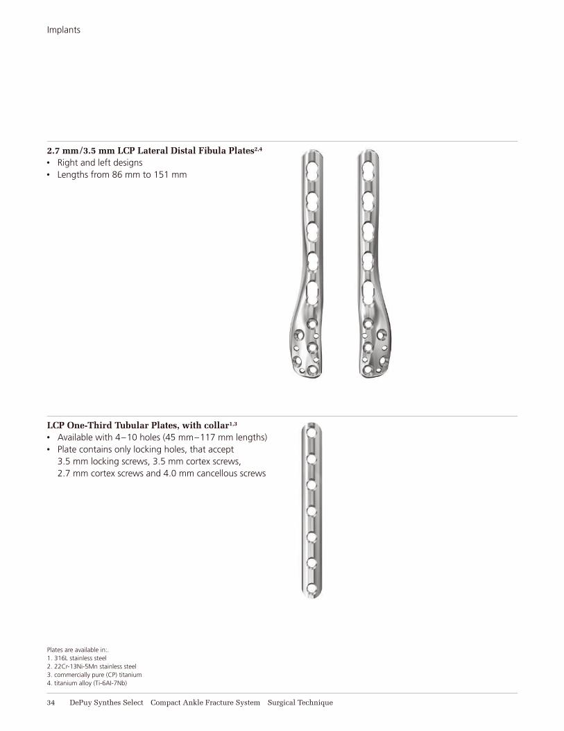
2.7 mm/3.5 mm LCP Lateral Distal Fibula Plates2,4
• Right and left designs• Lengths from 86 mm to 151 mm
LCP One-Third Tubular Plates, with collar1,3
• Available with 4–10 holes (45 mm–117 mm lengths) • Plate contains only locking holes, that accept
3.5 mm locking screws, 3.5 mm cortex screws, 2.7 mm cortex screws and 4.0 mm cancellous screws
Plates are available in:.1. 316L stainless steel2. 22Cr-13Ni-5Mn stainless steel3. commercially pure (CP) titanium4. titanium alloy (Ti-6AI-7Nb)
Compact Ankle Fracture System Surgical Technique DePuy Synthes Select 35
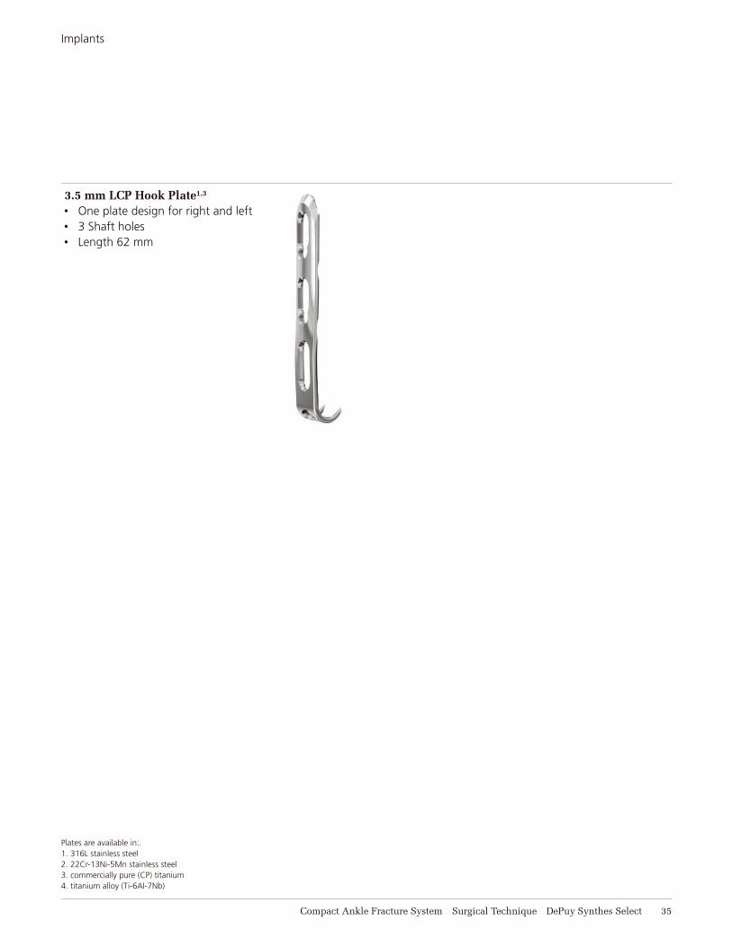
3.5 mm LCP Hook Plate1,3
• One plate design for right and left• 3 Shaft holes• Length 62 mm
Plates are available in:.1. 316L stainless steel2. 22Cr-13Ni-5Mn stainless steel3. commercially pure (CP) titanium4. titanium alloy (Ti-6AI-7Nb)
Implants
INSTRUMENTS
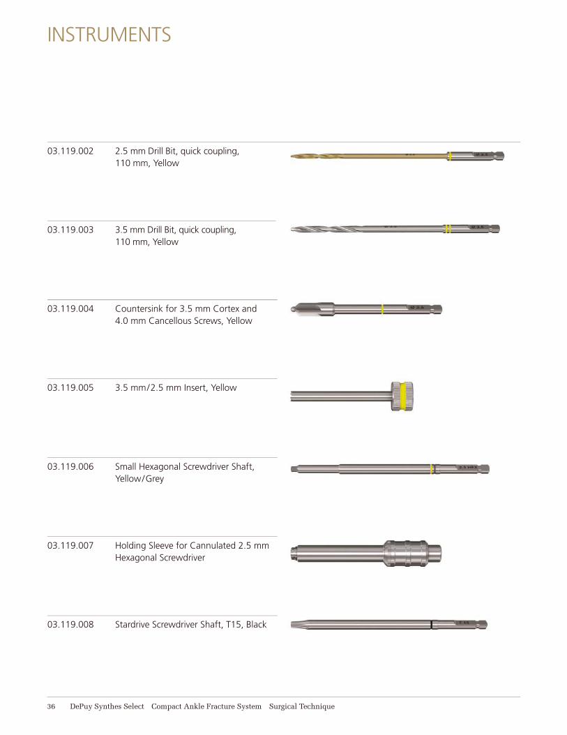
03.119.002 2.5 mm Drill Bit, quick coupling, 110 mm, Yellow
03.119.003 3.5 mm Drill Bit, quick coupling, 110 mm, Yellow
03.119.004 Countersink for 3.5 mm Cortex and 4.0 mm Cancellous Screws, Yellow
03.119.005 3.5 mm/2.5 mm Insert, Yellow
03.119.006 Small Hexagonal Screwdriver Shaft, Yellow/Grey
03.119.007 Holding Sleeve for Cannulated 2.5 mm Hexagonal Screwdriver
03.119.008 Stardrive Screwdriver Shaft, T15, Black
36 DePuy Synthes Select Compact Ankle Fracture System Surgical Technique

Instruments
03.119.009 3.5 mm Universal Drill Guide, Yellow
03.119.014 2.0 mm Drill Bit, quick coupling, 125 mm, Orange
03.119.015 2.7 mm Drill Bit, quick coupling, 100 mm, Orange
03.119.017 Countersink for 2.7 mm Cortex Screws, Purple/Orange
03.119.018 2.7 mm Universal Drill Guide, Orange
03.119.019 Stardrive Screwdriver Shaft, T8, 105 mm, Purple/Orange
03.119.024 2.7 mm/1.25 mm Double Drill Sleeve, Grey
Compact Ankle Fracture System Surgical Technique DePuy Synthes Select 37
Instruments
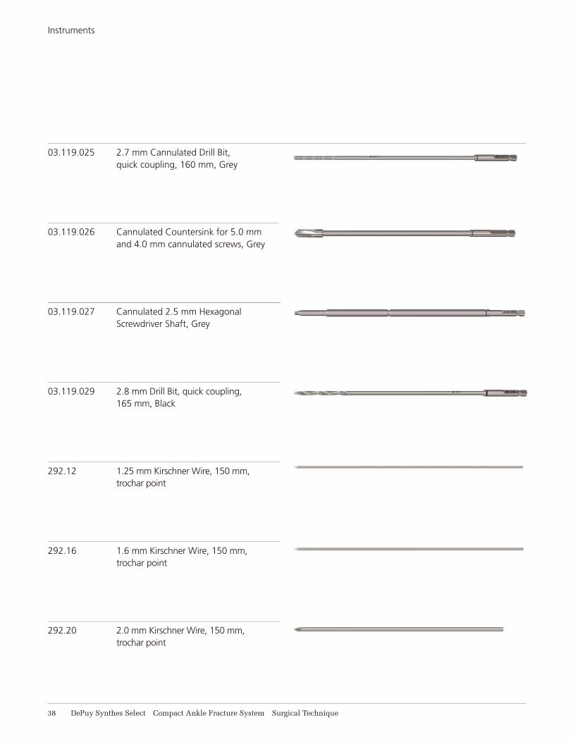
03.119.025 2.7 mm Cannulated Drill Bit, quick coupling, 160 mm, Grey
03.119.026 Cannulated Countersink for 5.0 mm and 4.0 mm cannulated screws, Grey
03.119.027 Cannulated 2.5 mm Hexagonal Screwdriver Shaft, Grey
03.119.029 2.8 mm Drill Bit, quick coupling, 165 mm, Black
292.12 1.25 mm Kirschner Wire, 150 mm, trochar point
292.16 1.6 mm Kirschner Wire, 150 mm, trochar point
292.20 2.0 mm Kirschner Wire, 150 mm,trochar point
38 DePuy Synthes Select Compact Ankle Fracture System Surgical Technique

Instruments
311.43 Handle with quick coupling
312.648 2.8 mm Threaded Drill Guide
313.353 Drill Sleeve for 2.0 mm Drill Bit
314.06 Holding Sleeve
314.468 Holding Sleeve for 314.467
319.01 Depth Gauge for 2.7 mm and 3.5 mm Cortex and 4.0 Cancellous Screws
319.15 Cannulated Screw Measuring Device for 3.5 mm and 4.0 mm screws
Compact Ankle Fracture System Surgical Technique DePuy Synthes Select 39
Instruments
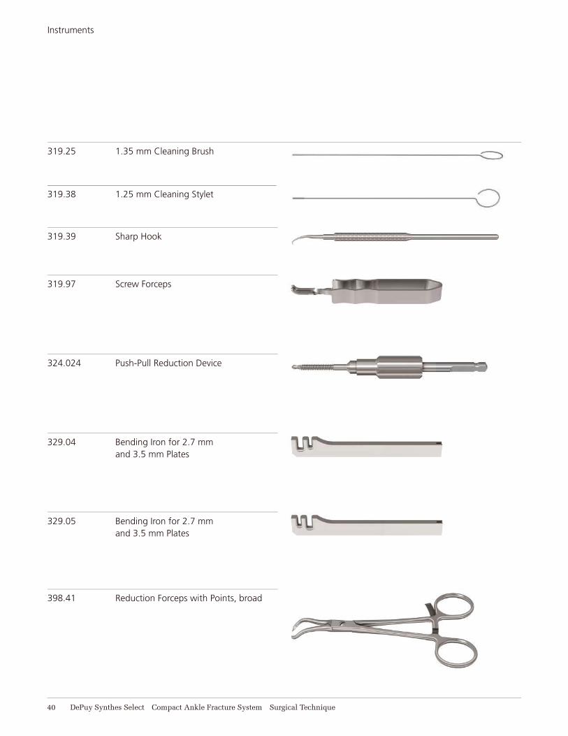
319.25 1.35 mm Cleaning Brush
319.38 1.25 mm Cleaning Stylet
319.39 Sharp Hook
319.97 Screw Forceps
324.024 Push-Pull Reduction Device
329.04 Bending Iron for 2.7 mm and 3.5 mm Plates
329.05 Bending Iron for 2.7 mm and 3.5 mm Plates
40 DePuy Synthes Select Compact Ankle Fracture System Surgical Technique
398.41 Reduction Forceps with Points, broad
Compact Ankle Fracture System Surgical Technique DePuy Synthes Select 41
Instruments
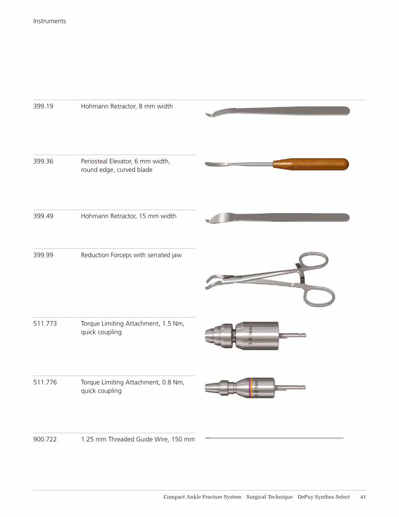
399.19 Hohmann Retractor, 8 mm width
399.36 Periosteal Elevator, 6 mm width, round edge, curved blade
399.49 Hohmann Retractor, 15 mm width
399.99 Reduction Forceps with serrated jaw
511.773 Torque Limiting Attachment, 1.5 Nm, quick coupling
511.776 Torque Limiting Attachment, 0.8 Nm, quick coupling
900.722 1.25 mm Threaded Guide Wire, 150 mm
42 DePuy Synthes Select Compact Ankle Fracture System Surgical Technique
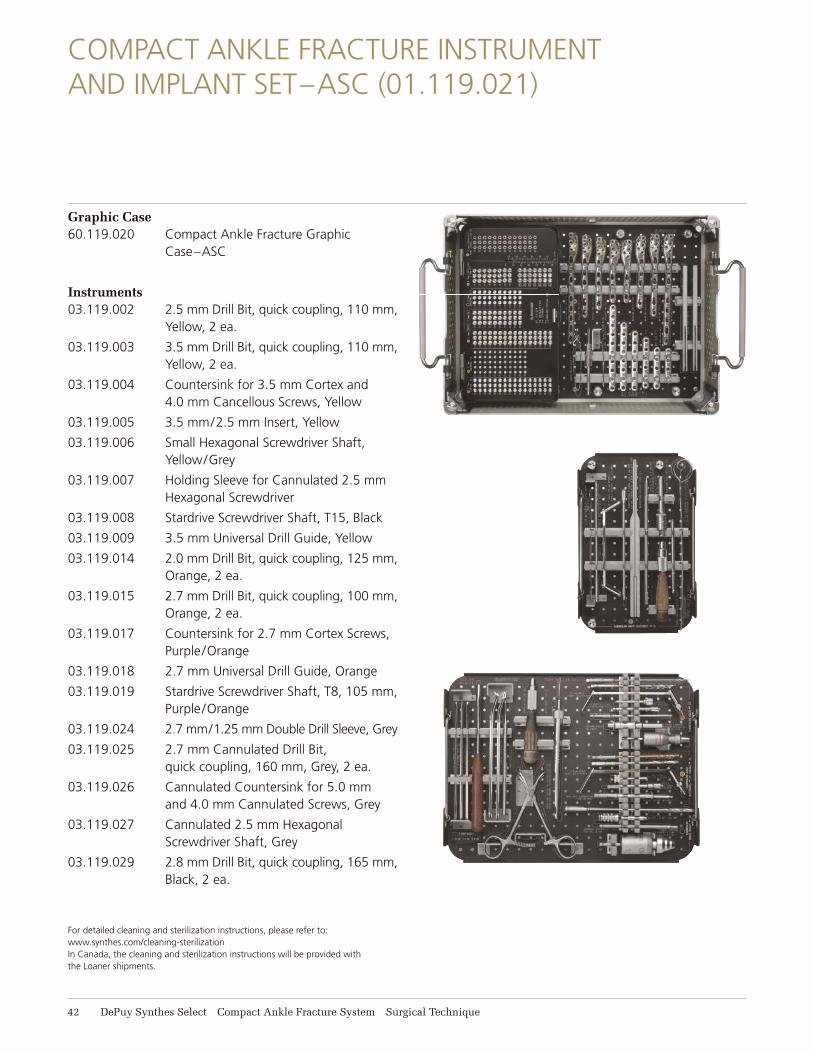
COMPACT ANKLE FRACTURE INSTRUMENT AND IMPLANT SET–ASC (01.119.021)
Graphic Case60.119.020 Compact Ankle Fracture Graphic
Case–ASC
Instruments03.119.002 2.5 mm Drill Bit, quick coupling, 110 mm,
Yellow, 2 ea.
03.119.003 3.5 mm Drill Bit, quick coupling, 110 mm, Yellow, 2 ea.
03.119.004 Countersink for 3.5 mm Cortex and 4.0 mm Cancellous Screws, Yellow
03.119.005 3.5 mm/2.5 mm Insert, Yellow
03.119.006 Small Hexagonal Screwdriver Shaft, Yellow/Grey
03.119.007 Holding Sleeve for Cannulated 2.5 mm Hexagonal Screwdriver
03.119.008 Stardrive Screwdriver Shaft, T15, Black
03.119.009 3.5 mm Universal Drill Guide, Yellow
03.119.014 2.0 mm Drill Bit, quick coupling, 125 mm, Orange, 2 ea.
03.119.015 2.7 mm Drill Bit, quick coupling, 100 mm, Orange, 2 ea.
03.119.017 Countersink for 2.7 mm Cortex Screws, Purple/Orange
03.119.018 2.7 mm Universal Drill Guide, Orange
03.119.019 Stardrive Screwdriver Shaft, T8, 105 mm, Purple/Orange
03.119.024 2.7 mm/1.25 mm Double Drill Sleeve, Grey
03.119.025 2.7 mm Cannulated Drill Bit, quick coupling, 160 mm, Grey, 2 ea.
03.119.026 Cannulated Countersink for 5.0 mm and 4.0 mm Cannulated Screws, Grey
03.119.027 Cannulated 2.5 mm Hexagonal Screwdriver Shaft, Grey
03.119.029 2.8 mm Drill Bit, quick coupling, 165 mm, Black, 2 ea.
For detailed cleaning and sterilization instructions, please refer to: www.synthes.com/cleaning-sterilization In Canada, the cleaning and sterilization instructions will be provided with the Loaner shipments.
Compact Ankle Fracture Instrument and Implant Set–ASC (01.119.021)
Compact Ankle Fracture System Surgical Technique DePuy Synthes Select 43
Instruments continued
292.12 1.25 mm Kirschner Wire, 150 mm, trochar point, 10/pkg.
292.16 1.6 mm Kirschner Wire, 150 mm, trochar point, 10/pkg.
292.20 2.0 mm Kirschner Wire, 150 mm, trochar point, 10/pkg.
311.43 Handle with quick coupling, 2 ea.
312.648 2.8 mm Threaded Drill Guide, 2 ea.
313.353 Drill Sleeve for 2.0 mm Drill Bit, 2 ea.
314.06 Holding Sleeve
314.468 Holding Sleeve for 314.467
319.01 Depth Gauge for 2.7 mm and 3.5 mm Cortex, and 4.0 Cancellous Screws
319.15 Cannulated Screw Measuring Device for 3.5 mm and 4.0 mm screws
319.25 1.35 mm Cleaning Brush
319.38 1.25 mm Cleaning Stylet
319.39 Sharp Hook
319.97 Screw Forceps
324.024 Push-Pull reduction device
329.04 Bending Iron for 2.7 mm and 3.5 mm Plates
329.05 Bending Iron for 2.7 mm and 3.5 mm Plates
398.41 Reduction Forceps with Points, broad
399.19 Hohmann Retractor, 8 mm width, 2 ea.
399.36 Periosteal Elevator, 6 mm width, round edge, curved blade
399.49 Hohmann Retractor, 15 mm width, 2 ea.
399.99 Reduction Forceps with serrated jaw
511.773 Torque Limiting Attachment, 1.5 Nm, quick coupling
511.776 Torque Limiting Attachment, 0.8 Nm, quick coupling
900.722 1.25 mm Threaded Guide Wire, 150 mm, 10 ea.
Implants2.7 mm/3.5 mm LCP Lateral Distal Fibula Plates
Stainless steel† Holes Length (mm)
02.112.138 4 86 right
02.112.139 4 86 left
02.112.140 5 99 right
02.112.141 5 99 left
02.112.142 6 112 right
02.112.143 6 112 left
02.112.148 9 151 right
02.112.149 9 151 left
LCP One-Third Tubular Plates, with collar
Stainless steel* Holes Length (mm)
241.341 4 45
241.351 5 57
241.361 6 69
241.371 7 81
241.381 8 93
241.401 10 117
3.5 mm LCP Hook Plate
Stainless steel* Holes Length (mm)
02.113.103 3 62
2.7 mm Locking Screws, self-tapping, with T8 StarDrive recess, 5 ea.
Length Length Stainless steel** (mm) Stainless steel (mm)
202.210 10 202.222 22
202.212 12 202.224 24
202.214 14 202.226 26
202.216 16 202.228 28
202.218 18 202.230 30
202.220 20† 22Cr-13Ni-5Mn stainless steel. Plates are also available in titanium alloy (Ti-6Al-7Nb).
* 316L stainless steel. Plates/screws are also available in Commercially pure (CP) titanium.
** 316L stainless steel. Plates/screws are also available in titanium alloy (Ti-6Al-7Nb).

Compact Ankle Fracture Instrument and Implant Set–ASC (01.119.021)
44 DePuy Synthes Select Compact Ankle Fracture System Surgical Technique
Implants continued
2.7 mm Cortex Screw, self-tapping, with T8 StarDrive recess, 3 ea.
Length Length Stainless steel** (mm) Stainless steel** (mm)
202.870 10 202.892 32
202.872 12 202.894 34
202.874 14 202.896 36
202.876 16 202.898 38
202.878 18 202.900 40
202.880 20 202.962 42
202.882 22 202.963 44
202.884 24 202.965 46
202.886 26 202.966 48
202.888 28 202.967 50
202.890 30
3.5 mm Locking Screws, self-tapping, with StarDrive recess, 3 ea.
Length Length Stainless steel** (mm) Stainless steel** (mm)
212.101 10 212.107 22
212.102 12 212.108 24
212.103 14 212.109 26
212.104 16 212.110 28
212.105 18 212.111 30
212.106 20
3.5 mm Cortex Screws, with low-profile head, self-tapping, hex drive recess
Stainless steel* Length (mm) Qty.
02.206.010 10 6
02.206.012 12 6
02.206.014 14 6
02.206.016 16 6
02.206.018 18 6
02.206.020 20 3
02.206.022 22 3
02.206.024 24 3
02.206.026 26 3
02.206.028 28 3
02.206.030 30 3
02.206.032 32 3
02.206.034 34 3
02.206.036 36 3
02.206.038 38 3
02.206.040 40 3
02.206.042 42 3
02.206.044 44 3
02.206.046 46 3
02.206.048 48 3
02.206.050 50 3
02.206.052 52 3
02.206.054 54 3
02.206.056 56 3
02.206.058 58 3
02.206.060 60 3
* 316L stainless steel. Plates/screws are also available in Commercially pure (CP) titanium.
** 316L stainless steel. Plates/screws are also available in titanium alloy (Ti-6Al-7Nb).
Compact Ankle Fracture Instrument and Implant Set–ASC (01.119.021)
Compact Ankle Fracture System Surgical Technique DePuy Synthes Select 45
Implants continued
4.0 mm Cancellous Bone Screws, fully threaded, 3 ea.
Length Length Stainless steel* (mm) Stainless steel* (mm)
206.010 10 206.018 18
206.012 12 206.020 20
206.014 14 206.022 22
206.016 16 206.024 24
4.0 mm Cancellous Bone Screws, partially threaded, 3 ea.
Length Length Stainless steel* (mm) Stainless steel* (mm)
207.030 30 207.050 50
207.035 35 207.055 55
207.040 40 207.060 60
207.045 45
4.0 mm Cannulated Screws, short thread, 3 ea.
Length Length Stainless steel** (mm) Stainless steel** (mm)
207.620 20 207.636 36
207.622 22 207.638 38
207.624 24 207.640 40
207.626 26 207.642 42
207.628 28 207.644 44
207.630 30 207.646 46
207.632 32 207.648 48
207.634 34 207.650 50
Washer, 7.0 mm
Stainless steel** Qty.
219.98 6
* 316L stainless steel. Plates/screws are also available in Commercially pure (CP) titanium.
** 316L stainless steel. Plates/screws are also available in titanium alloy (Ti-6Al-7Nb).
Also available01.119.022 Titanium Compact Ankle Fracture
Instrument and Implant Set
Synthes (Canada) Ltd. 2566 Meadowpine Boulevard Mississauga, Ontario L5N 6P9 Telephone: (905) 567-0440 To order: (800) 668-1119 Fax: (905) 567-3185
Synthes Inc.1302 Wrights Lane EastWest Chester, PA 19380 Telephone: (610) 719-5000 To order: (800) 523-0322
www.depuysynthes.com
© DePuy Synthes Trauma, a division of DOI 2013. All rights reserved.J12439-A 9/13
Top Related