


Languages
Pages
Legal


8
COLOR DIAGRAMS
Page 8-190-859494R1 JUNE 2000
COLOR DIAGRAMS
Table of Contents
2.5 Litre OptiMax 2000 Model Year Analog Wiring Diagram Page 8-3. . . . . . . . . . . . . . . . . . . . . . . . 2.5 Litre OptiMax 2000 Model Year Digital Wiring Diagram Page 8-5. . . . . . . . . . . . . . . . . . . . . . . . 2.5 Litre OptiMax 2001 Model Year Wiring Diagram Page 8-7. . . . . . . . . . . . . . . . . . . . . . . . Typical SmartCraft (Non CAN) Installation 2000 Model Year Page 8-9. . . . . . . . . . . . . . . . . . . . . . .
Typical SmartCraft Control Area Network (CAN) Installation 2001 Model Year Page 8-11. . . . . . . . . . . . . 2.5 Litre OptiMax 2000 & 2001 Model Year Fuel & Air Flow Diagram Page 8-13. . . . . . . . . . . . . . . . 2.5 Litre OptiMax 2000 & 2001 Model Year Water Flow Diagram Page 8-15. . . . . . . . . . . . . . . . . . . .

COLOR DIAGRAMS
Page 8-2 90-857138R1 MAY 2000

COLOR DIAGRAMS
Page 8-390-859494R1 JUNE 2000
2.5 LITRE OPTIMAX2000 MODEL YEAR
ANALOG WIRING DIAGRAM

1. ECM
2. Ignition Coils
3. Fuel Injectors
4. Direct Injectors
5. Oil Pump
6. MAP Sensor
7. Block Pressure Sensor
8. Water Sensor
9. Shift Switch
10. Air Temperature Sensor
11. Throttle Position Sensor (TPS)
12. Crank Position Sensor
13. ECM Driver/Oil Pump Circuit 20 Ampere Fuse
14. Electric Fuel Pump 20 Ampere Fuse
15. Ignition Coil 20 Ampere Fuse
16. Accessories 20 Ampere Fuse
17. Low Oil Switch
18. Compressor Temperature Switch
19. Starter Solenoid
20. Starter Motor
21. 60 Ampere Alternator
22. Main Power Relay
23. Starboard Head Temperature Switch
24. To Remote Control Trim Switch
25. Cowl Mounted Trim Switch
26. Trim Down Relay
27. Trim Up Relay
28. To Trim Pump
29. To 12 Volt Battery
30. Trim Sender
31. Fuel Pump #1 (Inside Vapor Separator)
32. Fuel Pump #2 (Outside Vapor Separator)
33. Engine Harness
34. To Temperature Gauge
35. Low Oil Light
36. Over Heat Light
37. Water in Fuel Light
38. Accessory Power
39. Check Engine Light
40. DDT Test Port
41. SmartCraft Harness (8 pin)

123456789
101112131415161718192021222324
123456789
101112131415161718192021222324
123456789
1011121314151617181920212223242526272829303132
6
4
2
3
1
5
1
2
3
4
5
6
1
2
3
4
5
6
1 9 17
8 10 24
1
11
12
22
23
32
1 9 17
8 10 241
23
456
78
2.5 Litre OptiMax 2000 Model Year Analog
1
2
34
5
6
78 9 10 11
12
13 16
14 15
17
18
19
2021
22
23 2425
26 27
28
29
31 32
33
343536
37
38
39
40
41
30

COLOR DIAGRAMS
Page 8-590-859494R1 JUNE 2000
2.5 LITRE OPTIMAX2000 MODEL YEAR
DIGITAL WIRING DIAGRAM

1. ECM
2. Ignition Coils
3. Fuel Injectors
4. Direct Injectors
5. Oil Pump
6. MAP Sensor
7. Block Pressure Sensor
8. Water Sensor
9. Shift Switch
10. Air Temperature Sensor
11. Throttle Position Sensor (TPS)
12. Crank Position Sensor
13. ECM Driver/Oil Pump Circuit 20 Ampere Fuse
14. Electric Fuel Pump 20 Ampere Fuse
15. Ignition Coil 20 Ampere Fuse
16. Accessories 20 Ampere Fuse
17. Low Oil Switch
18. Compressor Temperature Switch
19. Starter Solenoid
20. Starter Motor
21. 60 Ampere Alternator
22. Main Power Relay
23. Starboard Head Temperature Switch
24. To Remote Control Trim Switch
25. Cowl Mounted Trim Switch
26. Trim Down Relay
27. Trim Up Relay
28. To Trim Pump
29. To 12 Volt Battery
30. Fuel Pump #1 (Inside Vapor Separator)
31. Fuel Pump #2 (Outside Vapor Separator)
32. Engine Harness
33. To Temperature Gauge
34. Low Oil Light
35. Over Heat Light
36. Water in Fuel Light
37. Accessory Power
38. Optional Analog Tacometer Signal Wire
39. Check Engine Light
40. To Boat Harness, Brown/White Connection toSmartCraft Data Link (ECM)
41. DDT Test Port
42. SmartCraft Data Link Connection
43. SmartCraft Harness (8 pin)

123456789101112131415161718192021222324
123456789101112131415161718192021222324
1234567891011121314151617181920212223242526272829303132
6
4
2
3
1
5
1
2
3
4
5
6
1
2
3
4
5
6
1 9 17
8 10 24
1
11
12
22
23
32
1 9 17
8 10 241
23
456
78
2.5 Litre OptiMax 2000 Model Year Digital
1
2
34
5
6
78 9 10 11
12
13 16
14 15
17
18
19
2021
22
23 2425
26 27
28
29
30 31
32
3334
3536
3738
39 4041 42
43

COLOR DIAGRAMS
Page 8-790-859494R1 JUNE 2000
2.5 LITRE OPTIMAX2001 MODEL YEARWIRING DIAGRAM

1. ECM
2. Ignition Coils
3. Coil Drivers
4. Fuel Injectors
5. Direct Injectors
6. Oil Pump
7. MAP Sensor
8. Block Pressure Sensor
9. Water Sensor
10. Shift Switch
11. Starboard Head Temperature Switch
12. Port Head Temperature Switch
13. Throttle Position Sensor (TPS)
14. Crank Position Sensor
15. Accessories 20 Ampere Fuse
16. ECM Driver/Oil Pump/Electric Fuel Pump Cir-cuit 20 Ampere Fuse
17. Ignition Coil 20 Ampere Fuse
18. Power Trim 20 Ampere Fuse
19. Low Oil Switch
20. Compressor Temperature Switch
21. Slave Solenoid
22. Starter Solenoid
23. Starter Motor
24. 60 Ampere Alternator
25. Air Temperature Sensor
26. Main Power Relay
27. To Remote Control Trim Switch
28. Cowl Mounted Trim Switch
29. Trim Down Relay
30. Trim Up Relay
31. To Trim Pump
32. To 12 Volt Battery
33. Fuel Pump #1 (Inside Vapor Separator)
34. Fuel Pump #2 (Outside Vapor Separator)
35. Accessory Power
36. Engine Harness
37. Data Buss (10 Pin) Control Area Network (CAN)
38. DDT Test Port
39. SmartCraft Data Link Connection
40. To Boat Harness, Brown/White Connection toSmartCraft Data Link (ECM)
41. SmartCraft Harness (8 pin)
42. Optional Analog Tachometer Signal Wire

123456789101112131415161718192021222324
123456789101112131415161718192021222324
1234567891011121314151617181920212223242526272829303132
1
3
5
2
4
6
1
3
5
2
4
6
1-4 3-6 2-5135 246
1
11
12
22
23
32
1
8
9
16
17
24
1
8
9
16
17
241
23
456
78
2.5 Litre OptiMax 2001 Model Year
2
3
45
67
8
9 10 11 12 13
14
15 17
16 18
19
20
21
22
23 24 25
26
27
28
29 30
31
32
3334
35
36
37
38 3940
1
41
42

COLOR DIAGRAMS
Page 8-990-859494R1 JUNE 2000
TYPICAL SMARTCRAFT (NON CAN)
INSTALLATION2000 MODEL YEAR

1. 8-Pin Digital Sensor Harness Extension Connection to Engine Wiring Harness
2. Digital Speedometer Sensor
3. Digital Trim Sender
4. 6-Pin Digital Sensor Harness
5. Connection for Analog Temperature Sender
6. Connections to Trim Relays
7. Connection to SmartCraft Data Link (ECM) Two Wire Harness
8. Remote Control Harness Connects to Engine Harness
9. Digital Connections for Fuel Sender
10. Digital Connections to Oil Sender
11. 4-Pin Digital Sensor Harness Connection to Paddle Wheel
12. Paddle Wheel/Lake/Sea Water Temperature Sender
13. Analog Temperature Gauge Connection
14. Warning Horn
15. Tachometer Harness
16. SmartCraft Tachometer Harness
17. Ignition Key Switch
18. Connections for Neutral Start Switch
19. Connections for Power Trim Switch
20. Connections for Lanyard Stop Switch
21. Mechanical Panel Control (MPC) 4000
22. Connection to 12 Volt Power Supply of Engine being Monitored
23. Connection for Optional Visual Warning Light
24. SmartCraft Tachometer
25. Connection Between SmartCraft Tachometer Harness and SmartCraft Tachometer
26. Connection Between SmartCraft Tachometer Harness and SmartCraft Speedometer Harness
27. Connection for Optional GPS
28. Connection Between SmartCraft Speedometer Harness and SmartCraft Speedometer
29. SmartCraft Speedometer
30. Connection for Ambient Air Temperature Sensor
31. Ambient Air Temperature Sensor
32. Connection for Second SmartCraft Tachometer (Dual Outboard Application)
33. SmartCraft Tachometer Harness (Dual Outboard Application)
34. SmartCraft Tachometer (Dual Outboard Application)
35. Connection for Optional Visual Warning Light (Dual Outboard Application)
36. Connection to 12 Volt Power Supply of Second Engine being Monitored (Dual Outboard Application)
37. Connection to Second Remote Control Tachometer Harness (Dual Outboard Application)

C
D E A
B
Typical SmartCraft (Non CAN) Installation 2000 Model Year
2
3
4
5
67
8
9 10
1112
13
14
15 16
17
1819
20
21
2223
24
25
26
27
28
29
30
31
32
33
34
35
36
37
1

COLOR DIAGRAMS
Page 8-1190-859494R1 JUNE 2000
TYPICAL SMARTCRAFT (CAN)
INSTALLATION2001 MODEL YEAR
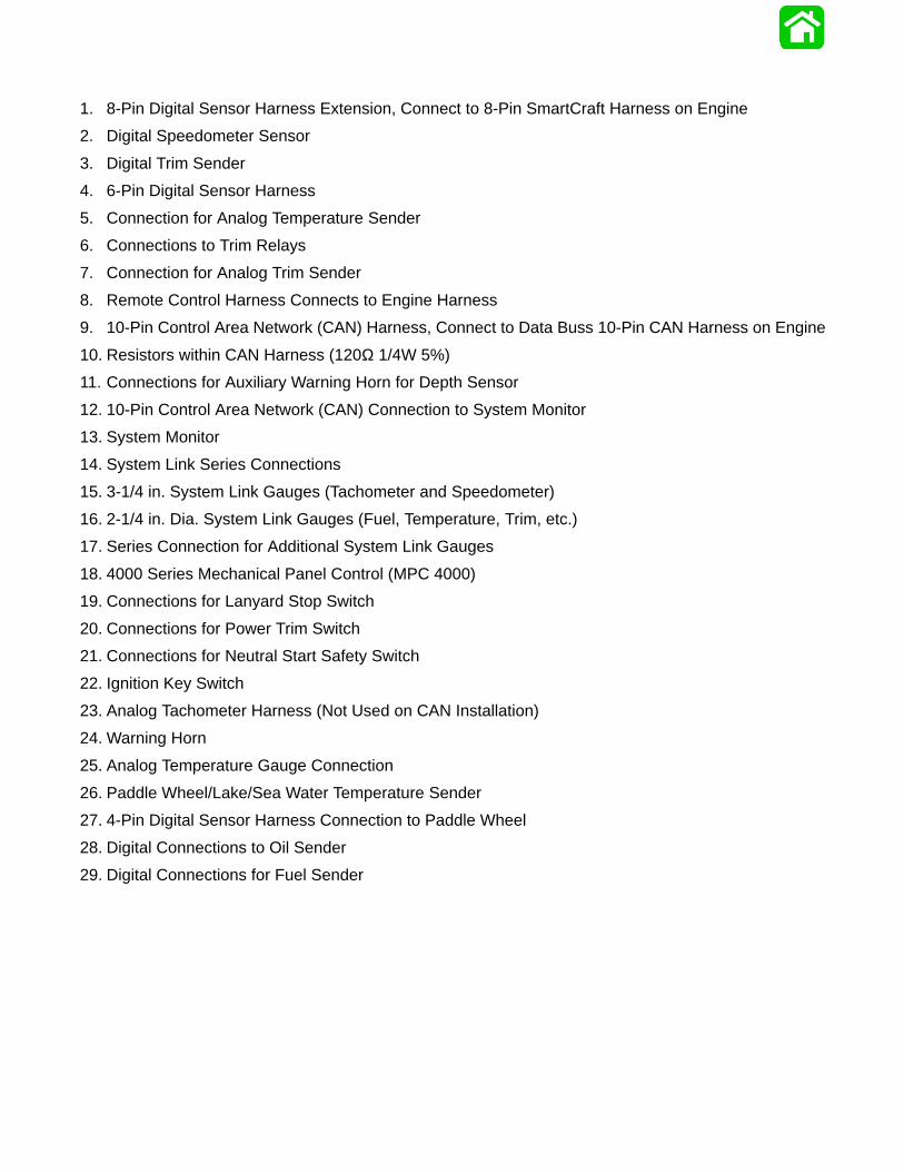
1. 8-Pin Digital Sensor Harness Extension, Connect to 8-Pin SmartCraft Harness on Engine
2. Digital Speedometer Sensor
3. Digital Trim Sender
4. 6-Pin Digital Sensor Harness
5. Connection for Analog Temperature Sender
6. Connections to Trim Relays
7. Connection for Analog Trim Sender
8. Remote Control Harness Connects to Engine Harness
9. 10-Pin Control Area Network (CAN) Harness, Connect to Data Buss 10-Pin CAN Harness on Engine
10. Resistors within CAN Harness (120Ω 1/4W 5%)
11. Connections for Auxiliary Warning Horn for Depth Sensor
12. 10-Pin Control Area Network (CAN) Connection to System Monitor
13. System Monitor
14. System Link Series Connections
15. 3-1/4 in. System Link Gauges (Tachometer and Speedometer)
16. 2-1/4 in. Dia. System Link Gauges (Fuel, Temperature, Trim, etc.)
17. Series Connection for Additional System Link Gauges
18. 4000 Series Mechanical Panel Control (MPC 4000)
19. Connections for Lanyard Stop Switch
20. Connections for Power Trim Switch
21. Connections for Neutral Start Safety Switch
22. Ignition Key Switch
23. Analog Tachometer Harness (Not Used on CAN Installation)
24. Warning Horn
25. Analog Temperature Gauge Connection
26. Paddle Wheel/Lake/Sea Water Temperature Sender
27. 4-Pin Digital Sensor Harness Connection to Paddle Wheel
28. Digital Connections to Oil Sender
29. Digital Connections for Fuel Sender

Typical SmartCraft (CAN) Installation 2001 Model Year
C
D E A
B
1
2
3
4
5
67
8
9
10
11
12
13
14
14 14 14
17
1515
16 16
18
19
20
21
22
23
24
25
26
27
2829
10

COLOR DIAGRAMS
Page 8-1390-859494R1 JUNE 2000
2.5 LITRE OPTIMAX2000 & 2001 MODEL YEAR
FUEL & AIR FLOW DIAGRAM

1. Fuel inlet from primer bulb
2. Engine Pulse Fuel Pump
3. Fuel line to Water Separating Fuel Filter – 2-8 psi (14-55 kPa)
4. Water Separating Fuel Filter in Vapor Separator Tank (VST) Assembly
5. Fuel outlet from VST
6. Fuel Inlet to Low Pressure Electric Fuel Pump
7. Fuel outlet from Low Pressure Electric Fuel Pump – 7-9 psi (48-62 kPa)
8. Fuel inlet to High Pressure Electric Fuel Pump.
9. Relief Passage – Unused fuel returning to VST
10. Air Vent to VST
11. Fuel outlet from High Pressure Electric Fuel Pump – 90 psi (620 kPa)
12. High pressure fuel Inlet to Air/Fuel Rails – 90 psi (620 kPa)
13. Fuel Injector is opened by the ECM, 90 psi (620 kPa) fuel is discharged into a machined cavity insidethe air chamber of the air/fuel rail. This mixes the fuel with the air charge.
14. Air Inlet to Air Compressor
15. Air Compressor
16. High Pressure Air Outlet – 80 psi (551 kPa)
17. High Pressure Air Inlet to Air/Fuel Rails – 80 psi (551 kPa)
18. Direct Injector discharges the air/fuel mixture into the combustion chamber
19. Schrader Valve for Testing Air Pressure
20. Schrader Valve for Testing Fuel Pressure
21. Air Pressure Regulator will limit the amount of pressure developed inside the air passages to approxi-mately 10 psi (69 kPa) below the pressure of the fuel inside the fuel passages (i.e. 80 psi [551 kPa] airvs 90 psi [620 kPa] fuel)
22. Bleed Off from Air Pressure Regulator, Routed to the Exhaust Adaptor and Exits thru the Propeller
23. Fuel Pressure Regulator not only regulates fuel pressure but also regulates it at approximately 10 p.s.i.(69 kPa) higher than whatever the air rail pressure is. The fuel regulator diaphragm is held closed witha spring that requires 10 p.s.i. (69 kPa) to force the diaphragm off the diaphragm seat. The back sideof the diaphragm is exposed to air rail pressure. As the air rail pressure increases, the fuel pressureneeded to open the regulator will equally increase.
24. Bleed off from Fuel Pressure Regulator, Routed Back to VST
25. Tracker Valve has a rubber diaphragm which expands and retracts to equalize the pulses developedby the pumps (both air and fuel).
26. Check Valve – 40 psi (276 kPa)
27. Fuel return inlet from Fuel Regulator
28. Water Inlet to cool port air/fuel rail and air compressor
29. Cooling water from Compressor routed to Tell-Tale

58621
2.5 Litre OptiMax Fuel and Air Flow 2000 & 2001 Models
1
2
3
4
5
6
7
8 9
10
11
12
15
16
17
18
19
20
21
22
23
24
25
26
27
12
13
13
13
13
13
13
14
17
18
18
18
1818
28
29

COLOR DIAGRAMS
Page 8-1590-859494R1 JUNE 2000
2.5 LITRE OPTIMAX2000 & 2001 MODEL YEARWATER FLOW DIAGRAM
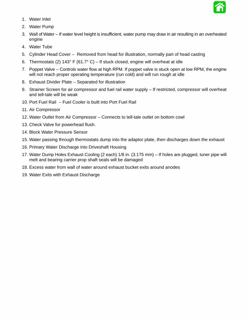
1. Water Inlet
2. Water Pump
3. Wall of Water – If water level height is insufficient, water pump may draw in air resulting in an overheatedengine
4. Water Tube
5. Cylinder Head Cover – Removed from head for illustration, normally part of head casting
6. Thermostats (2) 143° F (61.7° C) – If stuck closed, engine will overheat at idle
7. Poppet Valve – Controls water flow at high RPM. If poppet valve is stuck open at low RPM, the enginewill not reach proper operating temperature (run cold) and will run rough at idle
8. Exhaust Divider Plate – Separated for illustration
9. Strainer Screen for air compressor and fuel rail water supply – If restricted, compressor will overheatand tell-tale will be weak
10. Port Fuel Rail – Fuel Cooler is built into Port Fuel Rail
11. Air Compressor
12. Water Outlet from Air Compressor – Connects to tell-tale outlet on bottom cowl
13. Check Valve for powerhead flush.
14. Block Water Pressure Sensor
15. Water passing through thermostats dump into the adaptor plate, then discharges down the exhaust
16. Primary Water Discharge into Driveshaft Housing
17. Water Dump Holes Exhaust Cooling (2 each) 1/8 in. (3.175 mm) – If holes are plugged, tuner pipe willmelt and bearing carrier prop shaft seals will be damaged
18. Excess water from wall of water around exhaust bucket exits around anodes
19. Water Exits with Exhaust Discharge
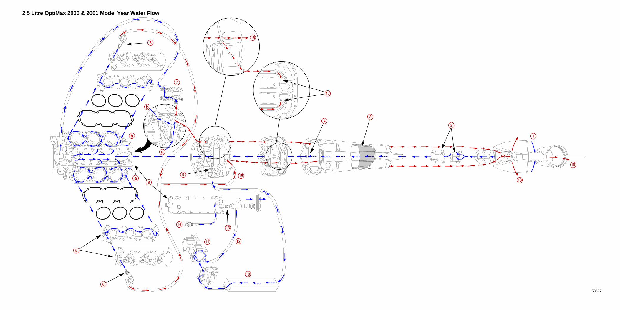
2.5 Litre OptiMax 2000 & 2001 Model Year Water Flow
58627
1
15
14
a
a
b
b
2
3
4
5
6
6
7
8
9
10
11 12
16
18
13
17
19
Top Related