


Languages
Pages
Legal

i
Cognitive Radio based Carrier Adaptation to the Doppler Spread of NB-IoT using performance analysis.
A Dissertation Submitted in Partial Fulfillment of Requirement for the Degree of Bachelor of Science in Electrical and Electronic Engineering
Submitted By:
Mainul Bin Ibrahim (152402)
Zaheen E Muktadi Syed (152404)
Tahmid Bakhtiar (152417)
S.M. Rhydh Arnab (152425)
Supervised By: Dr. Mohammed T. Kawser
Associate Professor, Department of Electrical and Electronic Engineering
ii
Cognitive Radio based Carrier Adaptation to theDoppler Spread for NB-IoT using performance
analysis.
By
Mainul Bin Ibrahim (152402)
Zaheen E Muktadi Syed (152404)
Tahmid Bakhtiar (152417)
S.M. Rhydh Arnab (152425)
A Thesis Submitted to the Academic Faculty in Partial Fulfillment of the Requirements for the Degree of
BACHELOR OF SCIENCE IN ELECTRICAL AND ELECTRONIC ENGINEERING
Department of Electrical and Electronic Engineering Islamic University of Technology (IUT)
Gazipur, Bangladesh
November 2019

3
Declaration of Candidate
It is hereby declared that this thesis or any part of it has not been submitted elsewhere for the
award of any Degree or Diploma.
Prof. Dr. Mohammad T. Kawser Associate Professor Department of Electrical and Electronic Engineering Islamic University of Technology Date: 12 November, 2019
Mainul Bin Ibrahim Student no. 152402 Academic Year: 2018-19 Date: 12 November, 2019
Zaheen E Muktadi Syed Student no. 152404 Academic Year: 2018-19 Date: 12 November, 2019
Tahmid Bakhtiar Student no. 152417 Academic Year: 2018-19 Date: 12 November, 2019
S.M. Rhydh ArnabStudent no. 152425Academic Year: 2018-19Date: 12 November, 2019
4
Abstract In this book we aimed to integrate cognitive radio with narrow band internet of things (NB IoT).
The popularity of IoT devices have led to the invention of many popular machine-to-machine
(m2m) communication. NB IoT is one of the most powerful candidates fulfilling the fundamental
targets of low power wide area networks technologies built for IoT devices. We have summarized
the details of NB IoT and its eventual evolution. While much of the NB IoT are already well
published so we focused on summarizing the entire technology and developing a performance
analysis. Furthermore, we indulged ourselves in finding the relation of NB IoT with large doppler
spread. Thus, we carried simulations for different fading environment and variable doppler
frequencies. The performance was measured in terms of BLER and throughput and the results
were plotted with respect to variable SNR or Doppler frequencies. Our study shows agrees with
the commonly accepted relation of doppler spread with BLER and throughput. That is as doppler
frequency increases the throughput decrease sand BLER increases. However, the performance
analysis is implicating the underlying problem that is the degradation of NB IoT performance at
higher speed or higher doppler spread. To solve this, we turned to cognitive radio which is a clever
way of allocating resources or switching carrier frequency or even changing operation mode of
NB IoT suitably to enhance the overall performance. The data simulated can be used as a basis
for cognitive radio to properly acknowledge the extent of carrier frequency change required to
significantly improve the network performance.
5
Table of Contents
Chapter 1: Introduction ............................................................................................................................... 19
1.1. Internet of Things (IOT) ......................................................................................................... 20
1.2. Low Power Wide Area Network (LPWAN) ........................................................................... 27
1.3. Sigfox ...................................................................................................................................... 32
1.4. LoRa ........................................................................................................................................ 36
1.5. NB IOT ................................................................................................................................... 39
1.6. Comparative analysis between SigFox, Lora, and NB IoT ..................................................... 40
Chapter 2: Narrow Band Internet of Things ............................................................................................... 41
2.1. LOW POWER CONSUMPTION ............................................................................................... 43
2.2. ENHANCED COVERAGE AND LOW LATENCY SENSITIVITY ....................................... 44
2.3. TRANSMISSION MODE .......................................................................................................... 45
2.4. SPECTRUM RESOURCE .......................................................................................................... 46
2.5. WORKING MODE OF NB-IOT ................................................................................................ 46
Chapter 3: Doppler Spread .......................................................................................................................... 47
3.1. What is Doppler Effect? .............................................................................................................. 47
3.2. Frequency dispersion in RF ........................................................................................................ 48
3.1. Fading ......................................................................................................................................... 50
3.2. Effect of Doppler frequency on NB IoT ..................................................................................... 51
Chapter 4: Cognitive Radio ........................................................................................................................ 52
4.1. Introduction: ................................................................................................................................ 52
4.2. HISTORY ................................................................................................................................... 52
4.3. Functions: .................................................................................................................................... 53
4.4. Application .................................................................................................................................. 56
4.5. Advantages: ................................................................................................................................. 56
4.6. Cognitive Radio and NB-IOT: .................................................................................................... 57
4.7. The Proposed Algorithm ............................................................................................................. 58
Chapter 5: Simulation and Result Analysis ................................................................................................ 60
5.1: Simulation parameters ..................................................................................................................... 60
5.2 Simulation results for uplink signal .................................................................................................. 63
The data set: ............................................................................................................................................ 63
The Plots ................................................................................................................................................. 63
5.3: Performance analysis of Uplink signal ............................................................................................ 65
The data sets ............................................................................................................................................ 65
The plots ................................................................................................................................................. 66

6
5.4 Simulation results for Downlink signal ............................................................................................ 67
The Data set ............................................................................................................................................ 67
The Plots ................................................................................................................................................. 68
5.3: Performance analysis of Downlink signal ....................................................................................... 69
The data sets ............................................................................................................................................ 69
The Plots ................................................................................................................................................. 70
Chapter 6: Conclusion and Future reference ............................................................................................... 71
4.1. Book Summary ........................................................................................................................... 71
4.2. Future Plans: ............................................................................................................................... 72
References ................................................................................................................................................... 73

7
List of Tables:
Table 1: Parameters for SigFox Systems .................................................................35
Table 2: Parameter of LORA ...................................................................................38
Table 3 Comparative analysis of LPWAN ..............................................................40
Table 4 Part 1 of the 3GPP release summary of NB IoT .........................................42
Table 5; Part 2 of the 3GPP release summary of NB IoT .......................................43
Table 6: Specifications of NB IoT ...........................................................................44
Table 7: Simulation parameters ...............................................................................61
Table 8: Data set for Uplink Simulations ................................................................63
Table 9: Data sets for UL SNR vs Doppler frequency ............................................65
Table 10: Data set DL ..............................................................................................67
Table 11: Data sets of SNR vs Doppler Frequency DL ..........................................69
8
List of Figures:
Figure 1: Applications of IoT devices. ......................................................................................... 26
Figure 2: LPWAN positioning with respect to radio communication technology. ...................... 27
Figure 3: Types of LPWAN .......................................................................................................... 29
Figure 4: Demonstration of Doppler frequency ............................................................................ 48
Figure 5:Demonstration of Doppler frequency. ............................................................................ 48
Figure 6:Multipath channel model ................................................................................................ 49
Figure 7: Spectrum Management of CR ....................................................................................... 54
Figure 8: The Algorithm ............................................................................................................... 59
Figure 9: Modes of Operation of NB IoT ..................................................................................... 62
Figure 11: Throughput vs SNR for different Doppler frequency ................................................. 64
Figure 12 BLER vs SNR for different Doppler Frequency .......................................................... 64
Figure 13 Throughput vs Doppler frequency for different SNR values ....................................... 66
Figure 14 BLER vs Doppler frequency for different SNR values ................................................ 66
Figure 15 Throughput vs SNR for different Doppler Frequency ................................................. 68
Figure 16 BLER vs SNR for different Doppler Frequency .......................................................... 68
Figure 17 Throughput vs Doppler frequency for different SNR values ....................................... 70
Figure 18 BLER vs Doppler frequency for different SNR values ................................................ 70

9
Symbols and Acronyms:
3GPP Third-generation partnership project
AAS Active antenna systems
ACIR Adjacent channel interference ratio
ACK Acknowledgment (in ARQ protocols)
ACLR Adjacent channel leakage ratio
ACS Adjacent channel selectivity
AGC Automatic gain control
AIFS Arbitration interframe space
AM Acknowledged mode (RLC configuration)
A-MPR Additional maximum power reduction
APT Asia-Pacific tele community
ARI Acknowledgment resource indicator
ARIB Association of radio industries and businesses
ARQ Automatic repeat-request
AS Access stratum
ATC Ancillary terrestrial component
ATIS Alliance for telecommunications industry solutions
AWGN Additive white Gaussian noise
BC Band category
BCCH Broadcast control channel
BCH Broadcast channel
BL Bandwidth-reduced low complexity
BM-SC Broadcast multicast service center
BPSK Binary phase-shift keying
BS Base station
BW Bandwidth
CA Carrier aggregation
CACLR Cumulative adjacent channel leakage ratio

10
CC Component carrier
CCA Clear channel assessment
CCCH Common control channel
CCE Control channel element
CCSA China Communications Standards Association
CDMA Code-division multiple access
CITEL Inter-American Telecommunication Commission
B-MTC Critical MTC
C-CN Core network
CoMP Coordinated multi-point transmission/reception
CP Cyclic prefix
CQI Channel-quality indicator
CRC Cyclic redundancy check
D-RNTI Cell radio-network temporary identifier
CRS Cell-specific reference signal
CS Capability set (for MSR base stations)
CSA Common subframe allocation
CSG Closed Subscriber Group
CSI Channel-state information
CSI-IM CSI interference measurement
CSI-RS CSI reference signals
CW Continuous wave
D2D Device-to-device
DAI Downlink assignment index
DCCH Dedicated control channel
DCH Dedicated channel
DCI Downlink control information
DCF Distributed coordination function
DFS Dynamic frequency selection
DFT Discrete Fourier transform
11
DL Downlink
DL-SCH Downlink shared channel
DM-RS Demodulation reference signal
DMTC DRS measurements timing configuration
DRS Discovery reference signal
DRX Discontinuous reception
DTCH Dedicated traffic channel
DTX Discontinuous transmission
DwPTS Downlink part of the special subframe (for TDD operation) ECCE
Enhanced control channel element
EDCA Enhanced distributed channel access
EDGE Enhanced data rates for GSM evolution; enhanced data rates
for global evolution
eIMTA Enhanced Interference mitigation and traffic adaptation
EIRP Effective isotropic radiated power
EIS Equivalent isotropic sensitivity
EMBB Enhanced MBB
eMTC Enhanced machine-type communication
eNB eNodeB
eNodeB E-UTRAN NodeB
EPC Evolved packet core
EPS Evolved packet system
EREG Enhanced resource-element group
ETSI European Telecommunications Standards Institute
E-UTRA Evolved UTRA
UTRAN Evolved UTRAN
EVM Error vector magnitude
FDD Frequency division duplex
FDMA Frequency-division multiple access
FEC Forward error correction
FFT Fast Fourier transform

12
GP Guard period (for TDD operation)
GPRS General packet radio services
GPS Global positioning system
GSM Global system for mobile communications
GSMA GSM Association
HARQ Hybrid ARQ HII High-interference indicator
HSFN Hyper system frame number
HSPA High-speed packet access
IEEE Institute of Electrical and Electronics Engineers
LAA License-assisted access
LAN Local area network
LBT Listen before talk
LCID Logical channel identifier
LDPC Low-density parity check code
LTE Long-term evolution
MAC Medium access control
MAN Metropolitan area network
MBB Mobile broadband
MBMS Multimedia broad cast multicast service
MC Multi-carrier
MCCH MBMS control channel
MCE MBMS coordination entity
MCG Master cell group
MCH Multicast channel
MCS Modulation and coding scheme
MIB Master information block
MIMO Multiple input multiple output
MLSE Maximum-likelihood sequence estimation
MME Mobility management entity
MPR Maximum power reduction
MSA MCH subframe allocation
13
MSI MCH scheduling information
MSP MCH scheduling period
MSR Multi-standard radio
MSS Mobile satellite service
MTC Machine-type communication
MTCH MBMS traffic channel
NAK Negative acknowledgment (in ARQ protocols)
NAICS Network-assisted interference cancelation and suppression
NAS Non-access stratum (a functional layer between the core
network and the terminal that supports signaling)
NB-IoT Narrow-band internet of things
NPSS Narrowband primary synchronization signal
NSSS Narrowband secondary synchronization signal
NRS Narrowband reference signal
NPBCH Narrowband physical broadcast channel
NPDSCH Narrowband physical downlink shared channel
NPDCCH Narrowband physical downlink control channel
NPRACH Narrowband physical random-access channel
NPUSCH Narrowband physical uplink shared channel
OFDM Orthogonal frequency-division multiplexing
OI Overload indicator
OOB Out-of-band (emissions)
OSDD OTA sensitivity direction declarations
OTA Over the air
PA Power amplifier
PAPR Peak-to-average power ratio
PAR Peak-to-average ratio (same as PAPR)
PBCH Physical broadcast channel
PCCH Paging control channel
PCFICH Physical control format indicator channel
PCG Project Coordination Group (in 3GPP)
14
PCH Paging channel
PCID Physical cell identity
PCRF Policy and charging rules function
PDC Personal digital cellular
PDCCH Physical downlink control channel
PDCP Packet data convergence protocol
PDSCH Physical downlink shared channel
PDN Packet data network
PDU Protocol data unit
P-GW Packet-data network gateway (also PDN-GW)
PHY Physical layer
PMCH Physical multicast channel
PMI Precoding-matrix indicator
PRACH Physical random-access channel
PRB Physical resource block
P-RNTI Paging RNTI ProSe Proximity services
PSBCH Physical sidelink broadcast channel
PSCCH Physical sidelink control channel
PSD Power spectral density
PSDCH Physical sidelink discovery channel
PSLSS Primary sidelink synchronization signal
PSM Power-saving mode
PSS Primary synchronization signal
PSSCH Physical sidelink shared channel
PSTN Public switched telephone networks
PUCCH Physical uplink control channel
PUSCH Physical uplink shared channel
QAM Quadrature amplitude modulation
QCL Quasi-colocation
QoS Quality-of-service
QPP Quadrature permutation polynomial

15
QPSK Quadrature phase-shift keying
RAB Radio-access bearer
RACH Random-access channel
RAN Radio-access network
RAT Radio-access technology
RB Resource block
RE Resource element
REG Resource-element group
RF Radio frequency
RI Rank indicator
RLAN Radio local area networks
RLC Radio link control
RNTI Radio-network temporary identifier
RNTP Relative narrowband transmit power
RoAoA Range of angle of arrival
ROHC Robust header compression
PDCCH Relay physical downlink control channel
RRC Radio-resource control
Q-RRM Radio resource management
RS Reference symbol
RSPC Radio interface specifications
RSRP Reference signal received power
RSRQ Reference signal received quality
RV Redundancy version
RX Receiver
SBCCH Sidelink broadcast control channel
SCG Secondary cell group
SCI Sidelink control information
SC-PTM Single-cell point to multipoint
SDMA Spatial division multiple access
SDO Standards developing organization
16
SDU Service data unit
SEM Spectrum emissions mask
SF Subframe
SFBC Space frequency block coding
SFN Single-frequency network (in general, see also MBSFN);
system frame number (in 3GPP).
SGW Serving gateway
SI System information message
SIB System information block
SIC Successive interference combining
SIFS Short interframe space
SIM Subscriber identity module
SINR Signal-to-interference-and-noise ratio
SIR Signal-to-interference ratio
SL-DCH Sidelink discovery channel
SLI Sidelink identity
SL-SCH Sidelink shared channel
SLSS Sidelink synchronization signal
SNR Signal-to-noise ratio
SORTD Spatial orthogonal-resource transmit diversity
SR Scheduling request
SRS Sounding reference signal
R-SLSS Secondary sidelink synchronization signal
S-SSS Secondary synchronization signal
STCH Sidelink traffic channel
STBC Space time block coding
STC Space time coding
STTD Space time transmit diversity
TAB Transceiver array boundary
TCP Transmission control protocol

17
TDD Time-division duplex
TDMA Time-division multiple access
TF Transport format
TPC Transmit power control
TR Technical report
TRP Time repetition pattern; transmission reception point
TRPI Time repetition pattern index
TS Technical specification
TSDSI Telecommunications Standards Development Society, India TSG
TTA Telecommunications Technology Association
TTC Telecommunications Technology Committee
TTI Transmission time interval
TX Transmitter
UCI Uplink control information
UE User equipment (the 3GPP name for the mobile terminal)
UL Uplink
UL-SCH Uplink shared channel
UM Unacknowledged mode (RLC configuration)
UMTS Universal mobile telecommunications system
URLLC Ultra-reliable low-latency communication
UTRA Universal terrestrial radio access
UTRAN Universal terrestrial radio-access network
VoIP Voice-over-IP
WCDMA Wideband code-division multiple access
WCS Wireless communications service
WG Working group
WiMAX Worldwide interoperability for microwave access
WLAN Wireless local area network
WMAN Wireless metropolitan area network
18
Acknowledgement. First, we thank Allah (SWT) from the bottom of our hearts as He enabled us and strengthen us to
conduct this research properly and complete our thesis. Foremost, we are highly grateful to our
respected supervisor, Dr. Mohammed T. Kawser, Associate Professor, department of EEE, IUT
for his guidance and support for this thesis. Without his bolstering influence as well as buttress to
move on, we would not be intrigued, let alone to work in this area of science. He truly inspires us
to be a genuine scientist and conduct research in a proper constructive way.
We would like to thank all the faculty members of EEE Department, IUT for their continuous
support and encouragement. They provided a friendly environment for us to learn and grow. A
huge applaud for our senior brothers for guiding us and enlightening us in the course of learning.
Finally, our deepest of gratitude goes to our family who always listened to our sufferings and
enchanted us with their delightful words. Last but not the least we would like to thank our friends
who always supported us through this journey.
19
Chapter 1: Introduction
A network system that interconnects devices or any digital machines with each other with the
ability to share data over the network without requiring any human interaction is termed as Internet
of things, IOT and the devices are called IOT devices. These devices have certain requirement
mainly wide network, low data rate, low energy consumption, and cost effectiveness. The
application of IOT devices are diverse ranging from agriculture to smart homes. It is common
knowledge that in the recent times the number of IOT devices is booming. It is estimated that by
the year 2022 the number of IOT devices will reach approximately 22 billion. To accommodate
such big number of devices in the limited spectrum is a major challenge for telecommunication
engineers and one of the important features of 5G.
Statistically seen that 67% of the total IOT devices requires low data rate wide area network
(WAN) technologies which is known in the industry as Low-Power Wide-Area Network
(LPWAN) technology. Due to its greater popularity several industry grade LPWAN technology
already exists namely Sigfox, Lora, NB-IOT. While Sigfox and LORA work in the unlicensed
spectrum with a nonstandard and custom implemented network. NB-IOT, narrow-band Internet of
Things, is a representative of mature cellular communication technology. The standard for this
technology was developed by international standards organizations called 3GPP.
Numerous papers were published based on these machines to machine low powered wide area
networks. However, the increased popularity and urgency to accommodate a huge amount of IOT
devices with a highly efficient network has led us to further analyze the performance paradigm of
one of these technologies called Narrow band Internet of things and introduce the idea of cognitive
radio in NB- IOT. This proposal aims to solve the spectrum shortage and improve resource
allocation for the huge data traffic.
In this book we will discuss elaborately the implication and challenges of NB-IOT and how the
carrier adaptation can be manipulated effectively using cognitive radio which in turn is an isolated
solution for increased global data traffic.
We have organized the book in the following way: first we discuss about NB-IOT and it

20
evaluation, then we discuss its current challenges. Then we move on to the implications of doppler
spread, and the section following holds our simulation results for performance of NB-IOT and
finally cognitive radio.
1.1. Internet of Things (IoT)
The Internet of Things is an emerging topic of technical, social, and economic significance.
Consumer products, durable goods, cars and trucks, industrial and utility components, sensors, and
other everyday objects are being combined with Internet connectivity and powerful data analytic
capabilities that promise to transform the way we work, live, and play. Projections for the impact
of IoT on the Internet and economy are impressive, with some anticipating as many as 100 billion
connected IoT devices and a global economic impact of more than $11 trillion by 2025.
At the same time, however, the Internet of Things raises significant challenges that could stand in
the way of realizing its potential benefits. Attention-grabbing headlines about the hacking of
Internet-connected devices, surveillance concerns, and privacy fears already have captured public
attention. Technical challenges remain and new policy, legal and development challenges are
emerging.
This overview document is designed to help the Internet Society community navigate the dialogue
surrounding the Internet of Things in light of the competing predictions about its promises and
perils. The Internet of Things engages a broad set of ideas that are complex and intertwined from
different perspectives. Key concepts that serve as a foundation for exploring the opportunities and
challenges of IoT include:
IoT Definitions: The term Internet of Things generally refers to scenarios where network
connectivity and computing capability extends to objects, sensors and everyday items not normally
considered computers, allowing these devices to generate, exchange and consume data with
minimal human intervention. There is, however, no single, universal definition.
Enabling Technologies: The concept of combining computers, sensors, and networks to monitor
and control devices has existed for decades. The recent confluence of several technology market

21
trends, however, is bringing the Internet of Things closer to widespread reality. These include
Ubiquitous Connectivity, Widespread Adoption of IP-based Networking, Computing Economics,
Miniaturization, Advances in Data Analytics, and the Rise of Cloud Computing.
Connectivity Models: IoT implementations use different technical communications models, each
with its own characteristics. Four common communications models described by the Internet
Architecture Board include: Device-to-Device, Device-to-Cloud, Device-to-Gateway, and Back-
End Data-Sharing. These models highlight the flexibility in the ways that IoT devices can connect
and provide value to the user.
Transformational Potential: If the projections and trends towards IoT become reality, it may force
a shift in thinking about the implications and issues in a world where the most common interaction
with the Internet comes from passive engagement with connected objects rather than active
engagement with content. The potential realization of this outcome – a “hyperconnected world”
— is testament to the general-purpose nature of the Internet architecture itself, which does not
place inherent limitations on the applications or services that can make use of the technology.
Five key IoT issue areas are examined to explore some of the most pressing challenges and
questions related to the technology. These include security; privacy; interoperability and standards;
legal, regulatory, and rights; and emerging economies and development.
1.1.1. Security
While security considerations are not new in the context of information technology, the attributes
of many IoT implementations present new and unique security challenges. Addressing these
challenges and ensuring security in IoT products and services must be a fundamental priority.
Users need to trust that IoT devices and related data services are secure from vulnerabilities,
especially as this technology become more pervasive and integrated into our daily lives. Poorly
secured IoT devices and services can serve as potential entry points for cyber-attack and expose
user data to theft by leaving data streams inadequately protected.
The interconnected nature of IoT devices means that every poorly secured device that is connected
online potentially affects the security and resilience of the Internet globally. This challenge is
amplified by other considerations like the mass-scale deployment of homogenous IoT devices, the

22
ability of some devices to automatically connect to other devices, and the likelihood of fielding
these devices in unsecure environments.
As a matter of principle, developers and users of IoT devices and systems have a collective
obligation to ensure they do not expose users and the Internet itself to potential harm. Accordingly,
a collaborative approach to security will be needed to develop effective and appropriate solutions
to IoT security challenges that are well suited to the scale and complexity of the issues.
1.1.2. Privacy The full potential of the Internet of Things depends on strategies that respect individual privacy
choices across a broad spectrum of expectations. The data streams and user specificity afforded by
IoT devices can unlock incredible and unique value to IoT users, but concerns about privacy and
potential harms might hold back full adoption of the Internet of Things. This means that privacy
rights and respect for user privacy expectations are integral to ensuring user trust and confidence
in the Internet, connected devices, and related services.
Indeed, the Internet of Things is redefining the debate about privacy issues, as many
implementations can dramatically change the ways personal data is collected, analyzed, used, and
protected. For example, IoT amplifies concerns about the potential for increased surveillance and
tracking, difficulty in being able to opt out of certain data collection, and the strength of
aggregating IoT data streams to paint detailed digital portraits of users. While these are important
challenges, they are not insurmountable. In order to realize the opportunities, strategies will need
to be developed to respect individual privacy choices across a broad spectrum of expectations,
while still fostering innovation in new technology and services.
1.1.3. Interoperability and Standards A fragmented environment of proprietary IoT technical implementations will inhibit value for
users and industry. While full interoperability across products and services is not always feasible
or necessary, purchasers may be hesitant to buy IoT products and services if there is integration
inflexibility, high ownership complexity, and concern over vendor lock-in.
23
In addition, poorly designed and configured IoT devices may have negative consequences for the
networking resources they connect to and the broader Internet. Appropriate standards, reference
models, and best practices also will help curb the proliferation of devices that may act in disrupted
ways to the Internet. The use of generic, open, and widely available standards as technical building
blocks for IoT devices and services (such as the Internet Protocol) will support greater user
benefits, innovation, and economic opportunity.
1.1.4. Legal, Regulatory and Rights The use of IoT devices raises many new regulatory and legal questions as well as amplifies existing
legal issues around the Internet. The questions are wide in scope, and the rapid rate of change in
IoT technology frequently outpaces the ability of the associated policy, legal, and regulatory
structures to adapt.
One set of issues surrounds cross border data flows, which occur when IoT devices collect data
about people in one jurisdiction and transmit it to another jurisdiction with different data protection
laws for processing. Further, data collected by IoT devices is sometimes susceptible to misuse,
potentially causing discriminatory outcomes for some users. Other legal issues with IoT devices
include the conflict between law enforcement surveillance and civil rights; data retention and
destruction policies; and legal liability for unintended uses, security breaches or privacy lapses.
While the legal and regulatory challenges are broad and complex in scope, adopting the guiding
Internet Society principles of promoting a user’s ability to connect, speak, innovate, share, choose,
and trust are core considerations for evolving IoT laws and regulations that enable user rights.
1.1.5. Emerging Economy and Development Issues The Internet of Things holds significant promise for delivering social and economic benefits to
emerging and developing economies. This includes areas such as sustainable agriculture, water
quality and use, healthcare, industrialization, and environmental management, among others. As
such, IoT holds promise as a tool in achieving the United Nations Sustainable Development Goals.

24
The broad scope of IoT challenges will not be unique to industrialized countries. Developing
regions also will need to respond to realize the potential benefits of IoT. In addition, the unique
needs and challenges of implementation in less-developed regions will need to be addressed,
including infrastructure readiness, market and investment incentives, technical skill requirements,
and policy resources.
The Internet of Things is happening now. It promises to offer a revolutionary, fully connected
“smart” world as the relationships between objects, their environment, and people become more
tightly intertwined. Yet the issues and challenges associated with IoT need to be considered and
addressed in order for the potential benefits for individuals, society, and the economy to be
realized.
Ultimately, solutions for maximizing the benefits of the Internet of Things while minimizing the
risks will not be found by engaging in a polarized debate that pits the promises of IoT against its
possible perils. Rather, it will take informed engagement, dialogue, and collaboration across a
range of stakeholders to plot the most effective ways forward.
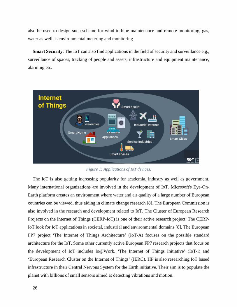
1.1.6. Applications of IoT
The IoT can find its applications in almost every aspect of our daily life. Below are some of the
examples.
Prediction of natural disasters: The combination of sensors and their autonomous
coordination and simulation will help to predict the occurrence of land-slides or other natural
disasters and to take appropriate actions in advance.
Industry applications: The IoT can find applications in industry e.g., managing a fleet of cars
for an organization. The IoT helps to monitor their environmental performance and process the
data to determine and pick the one that need maintenance.
Water Scarcity monitoring: The IoT can help to detect the water scarcity at different places.
The networks of sensors, tied together with the relevant simulation activities might not only

25
monitor long term water interventions such as catchment area management, but may even be used
to alert users of a stream, for instance, if an upstream event, such as the accidental release of
sewage into the stream, might have dangerous implications.
Design of smart homes: The IoT can help in the design of smart homes e.g., energy
consumption management, interaction with appliances, detecting emergencies, home safety and
finding things easily, home security etc.
Medical applications: The IoT can also find applications in medical sector for saving lives or
improving the quality of life e.g., monitoring health parameters, monitoring activities, support for
independent living, monitoring medicines intake etc.
Agriculture application: A network of different sensors can sense data, perform data
processing and inform the farmer through communication infrastructure e.g., mobile phone text
message about the portion of land that need particular attention. This may include smart packaging
of seeds, fertilizer and pest control mechanisms that respond to specific local conditions and
indicate actions. Intelligent farming system will help agronomists to have better understanding of
the plant growth models and to have efficient farming practices by having the knowledge of land
conditions and climate variability. This will significantly increase the agricultural productivity by
avoiding the inappropriate farming conditions.
Intelligent transport system design: The Intelligent transportation system will provide
efficient transportation control and management using advanced technology of sensors,
information and network. The intelligent transportation can have many interesting features such
as non-stop electronic highway toll, mobile emergency command and scheduling, transportation
law enforcement, vehicle rules violation monitoring, reducing environmental pollution, anti-theft
system, avoiding traffic jams, reporting traffic incidents, smart beaconing, minimizing arrival
delays etc.
Design of smart cities: The IoT can help to design smart cities e.g., monitoring air quality,
discovering emergency routes, efficient lighting up of the city, watering gardens etc.
Smart metering and monitoring: The IoT design for smart metering and monitoring will help
to get accurate automated meter reading and issuance of invoice to the customers. The IoT can
26
also be used to design such scheme for wind turbine maintenance and remote monitoring, gas,
water as well as environmental metering and monitoring.
Smart Security: The IoT can also find applications in the field of security and surveillance e.g.,
surveillance of spaces, tracking of people and assets, infrastructure and equipment maintenance,
alarming etc.
Figure 1: Applications of IoT devices.
The IoT is also getting increasing popularity for academia, industry as well as government.
Many international organizations are involved in the development of IoT. Microsoft's Eye-On-
Earth platform creates an environment where water and air quality of a large number of European
countries can be viewed, thus aiding in climate change research [8]. The European Commission is
also involved in the research and development related to IoT. The Cluster of European Research
Projects on the Internet of Things (CERP-IoT) is one of their active research project. The CERP-
IoT look for IoT applications in societal, industrial and environmental domains [8]. The European
FP7 project ‘The Internet of Things Architecture’ (IoT-A) focuses on the possible standard
architecture for the IoT. Some other currently active European FP7 research projects that focus on
the development of IoT includes Io@Work, ‘The Internet of Things Initiative’ (IoT-i) and
‘European Research Cluster on the Internet of Things’ (IERC). HP is also researching IoT based
infrastructure in their Central Nervous System for the Earth initiative. Their aim is to populate the
planet with billions of small sensors aimed at detecting vibrations and motion.
27
The IoT applications will continuously evolve with the passage of time but it has also to face many
challenges related to privacy, security, scale and complexity, sufficient spectrum for connecting
huge number of tagged objects or sensors etc.
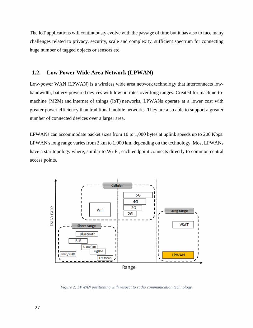
1.2. Low Power Wide Area Network (LPWAN) Low-power WAN (LPWAN) is a wireless wide area network technology that interconnects low-
bandwidth, battery-powered devices with low bit rates over long ranges. Created for machine-to-
machine (M2M) and internet of things (IoT) networks, LPWANs operate at a lower cost with
greater power efficiency than traditional mobile networks. They are also able to support a greater
number of connected devices over a larger area.
LPWANs can accommodate packet sizes from 10 to 1,000 bytes at uplink speeds up to 200 Kbps.
LPWAN's long range varies from 2 km to 1,000 km, depending on the technology. Most LPWANs
have a star topology where, similar to Wi-Fi, each endpoint connects directly to common central
access points.
Figure 2: LPWAN positioning with respect to radio communication technology.

28
1.2.1. Types of LPWANs
LPWAN is not a single technology, but a group of various low-power, wide area network
technologies that take many shapes and forms. LPWANs can use licensed or unlicensed
frequencies and include proprietary or open standard options.
The proprietary, unlicensed Sigfox is one of the most widely deployed LPWANs today. Running
over a public network in the 868 MHz or 902 MHz bands, the ultra-narrowband technology only
allows a single operator per country. While it can deliver messages over distances of 30-50 km in
rural areas, 3-10 km in urban settings and up to 1,000 km in line-of-site applications, its packet
size is limited to 150 messages of 12 bytes per day. Downlink packets are smaller, limited to four
messages of 8 bytes per day. Sending data back to endpoints can also be prone to interference.
Random phase multiple access, or RPMA, is a proprietary LPWAN from Ingenu Inc. Though it
has a shorter range (up to 50 km line of sight and with 5-10 km nonline of sight), it offers better
bidirectional communication than Sigfox. However, because it runs in the 2.4 GHz spectrum, it is
prone to interference from Wi-Fi, Bluetooth and physical structures. It also typically has higher
power consumption than other LPWAN options.
The unlicensed LoRa, specified and backed by the LoRa Alliance, transmits in several sub-
gigahertz frequencies, making it less prone to interference. A derivative of chirp spread spectrum
(CSS) modulation, LoRa allows users to define packet size. While open source, the underlying
transceiver chip used to implement LoRa is only available from Semtech Corporation, the
company behind the technology. LoRaWAN is the media access control (MAC) layer protocol
that manages communication between LPWAN devices and gateways.
Weightless SIG has developed three LPWAN standards: The unidirectional Weightless-N,
bidirectional Weightless-P and Weightless-W, which is also bidirectional and runs off of unused
TV spectrum. Weightless-N and Weightless-P are often more popular options due to Weightless-
W's shorter battery life. Weightless-N and Weightless-P run in the sub-1 GHz unlicensed spectrum
but also support licensed spectrum operation using 12.5 kHz narrowband technology.

29
Narrowband-IoT (NB-IoT) and LTE-M are both 3rd Generation Partnership Project (3GPP)
standards that operate on the licensed spectrum. While they have similar performance to other
standards, they operate on existing cellular infrastructure, allowing service providers to quickly
add cellular IoT connectivity to their service portfolios.
NB-IoT, also known as CAT-NB1, operates on existing LTE and Global System for Mobile
(GSM) infrastructure. It offers uplink and downlink rates of around 200 Kbps, using only 200 kHz
of available bandwidth.
Figure 3: Types of LPWAN
LTE-M, also known as CAT-M1, offers higher bandwidth than NB-IoT, and the highest bandwidth
of any LPWAN technology.
Some vendors, including Orange and SK Telecom, are deploying both licensed and unlicensed
technologies to capture both markets.
Other LPWAN technologies include:
• GreenOFDM from GreenWaves Technologies
• DASH7 from Haystack Technologies Inc.

30
• Symphony Link from Link Labs Inc.
• ThingPark Wireless from Actility
• Ultra-Narrow Band from various companies including Telensa, Nwave and Sigfox
• WAVIoT
1.2.2. LPWAN vs. cellular, RF, mesh
While Bluetooth, Zigbee and Wi-Fi are adequate for consumer-level IoT connectivity, many
IoT applications -- particularly in industrial, civic and commercial deployments -- benefit from an
LPWAN where large numbers of low-power devices in a wide area range can be supported cost-
effectively.
Unlike prior wireless technologies, LPWAN provides battery-efficient, ubiquitous wide-area
connectivity, enabling more M2M and IoT applications that were previously prohibitive due to
cost. However, a major tradeoff is the amount of data that can be transmitted. Yet, according to
James Brehm & Associates, 86% of all IoT devices use less than 3 MB of data per month, and
3GPP estimates that 99.9% of LPWAN devices will use less than 150 KB of data per month.
Cellular networks often suffer from poor battery life and may have gaps in coverage. Cellular
technologies are also frequently sunset. As many IoT devices are deployed for 10 years or longer,
sunsetting cellular coverage isn't a feasible option.
Radio frequency (RF) technologies, such as Bluetooth and near-field communications (NFC),
don't have the range many IoT applications require.
Mesh technologies, such as Zigbee, are better suited for medium-distance IoT applications such as
smart homes or smart buildings. They have high data rates and are far less battery-efficient than
LPWAN.

31
1.2.3. LPWAN applications
With decreased power requirements, longer ranges and lower costs than traditional mobile
networks, LPWANs enable a number of M2M and IoT applications, many of which were
previously constrained by budgets and power issues.
Choosing an LPWAN depends on the specific application, namely the desired speed, data amounts
and area covered. LPWANs are best suited for applications requiring infrequent uplink message
delivery of smaller messages. Most LPWAN technologies also have downlink capabilities.
LPWANs are commonly used in applications including smart metering, smart lighting, asset
monitoring and tracking, smart cities, precision agriculture, livestock monitoring, energy
management, manufacturing, and industrial IoT deployments.
1.2.4. LPWAN security
Different LPWAN technologies offer varying levels of security. Most include device or
subscriber authentication, network authentication, identity protection, advanced standard
encryption (AES), message confidentiality and key provisioning.
1.2.5. The future of LPWAN
As a fairly new technology, the LPWAN landscape is constantly changing and far from mature.
With many players in the market, it is unclear who the winner(s) will be, especially as the speed
of market expansion is also unknown. Long-term performance of each LPWAN variation is also
uncertain, as many are still in their initial rollouts and real-world testing at scale has not yet been
completed.

32
1.3. SigFox SigFox is a cellular style, long range, low power, low data rate form of wireless communications
that has been developed to provide wireless connectivity for devices like remote sensors, actuators
and other M2M and IoT devices.
The SigFox wireless interface has been developed to enable any communications that take place
to consume a minimum amount of power. In this way the remote devices can run on battery power
for very extended periods without the need for any battery changes or maintenance.
In addition to this, M2M and IoT communications will communications over extended distances
and the SigFox system has been designed to enable the transmissions to cover long distances,
enabling a limited number of base stations to be used.
Using a cellular style approach, the remote SigFox nodes are able to communicate with base
stations which have Internet connectivity, thereby enabling remote control and data collection from
anywhere with Internet connectivity.
In this way, SigFox is able to provide a low data rate connection to anywhere that is covered by a
network at very low cost for many M2M and IoT applications.
Thus, SigFox provides a cellular style network operator that provides a tailor-made solution for
low-throughput Internet of Things and M2M applications.
For a host of applications from smart meters to control nodes that need connectivity over long
ranges the only option until recently has been to use a cellular connection. This option has several
disadvantages because cellular phone systems are focussed on voice and high data rates. They are
not suited to low data rate connections as the radio interface is complex and this adds cost and
power consumption - too much for most M2M / IoT applications.
The SigFox network is aimed at providing connectivity for a variety of applications and users. It
is not aimed at one area, but at being for general use by a variety of different types of users. The
SIGFOX network performance is characterised by the following:
• Up to 140 messages per object per day

33
• Payload size for each message is 12 bytes
• Wireless throughput up to 100 bits per second
1.3.1. SigFox M2M application areas The SigFox network and technology is aimed at the low-cost machine to machine application areas
where wide area coverage is required. There are a number of applications that need this form of
low-cost wireless communications technology. Areas where the SigFox network may be used
include:
• Home and consumer goods
• Energy related communications - in particular smart metering
• Healthcare - in particular the mHealth applications that are starting to be developed
• Transportation - this can include the automotive management
• Remote monitoring and control
• Retail including point of sale, shelf updating, etc
• Security
1.3.2. SigFox radio access network In view of the low data rates used for IoT connections, the SIGFOX network employs Ultra-
Narrow Band, UNB technology. This enables very low transmitter power levels to be used while
still being able to maintain a robust data connection.
The SigFox radio link uses unlicensed ISM radio bands. The exact frequencies can vary according
to national regulations, but in Europe the 868MHz band is used; in the US it is 915MHz; and
433MHz in Asia.
The density of the cells in the SigFox network is based on an average range of about 30-50km in
rural areas and in urban areas where there are usually more obstructions and noise is greater the
range may be reduced to between 3 and 10km. Distances can be much higher for outdoor nodes
34
where SIGFOX states line of sight messages could travel over 1000km, although more usual
figures will be much less than this.
The overall SigFox network topology has been designed to provide a scalable, high-capacity
network, with very low energy consumption, while maintaining a simple and easy to rollout star-
based cell infrastructure.
SigFox operation is based around the use of very narrow bandwidths. The uplink and downlink
have different characteristics:
• Uplink: The uplink bandwidth is just 100 Hz in the European area, although 600 Hz is allowed
in the USA, and the modulation scheme is DBPSK, differential binary phase shift keying.
In Europe the uplink frequency availability is limited to frequencies between 868.00 and 868.60
MHz and the maximum power is limited to 25 mW. Also the European Union has limited the
maximum duty cycle to a maximum mean transmission time of 1% to fairly share the spectrum
usage between all users of this and other similar communications systems.
• Downlink: For the downlink the channel bandwidth is 1.5 kHz and GFSK, Gaussian
frequency shift keying is used as the modulation format. This provides a data rate of 600 bps.
The downlink frequency band is limited to frequencies between 869.40 and 869.65 MHz. In
the case of the downlink, the power output is limited to a maximum of 500mW with 10% duty
cycle. Again this duty cycle is limited by Eu regulations.
Although the duty cycle limitations affect all IoT / M2M type applications using the 868MHz
band, it limits the Sigfox data transmission. It means that the maximum length of a SigFox packet
is 24 bytes, and of this, the payload data may occupy a maximum of 12 bytes. Accordingly it can
be seen that with the data rate of 100bps each packet transmission takes about 2 seconds. Also
each transmission from a SigFox device consists of three packets transmitted each transmitted on
three different frequencies chosen from a pseudorandom sequence. The multiple transmission of
the data is sued to ensure the integrity of the data received.

35
Early versions of SigFox only supported uplink transmissions, but later the system evolved to
support bi-directional communication, even though there is significant link asymmetry as seen
from the details of the uplink and downlink.
In terms of the system protocol, the downlink communication, i.e., data from the base stations to
the end devices can only occur following an uplink communication.
Also, the number of messages sent each day is limited, making the system ideal for low data rate
remote monitoring nodes, etc. In view of this acknowledgements are not set, but the uplink
communication reliability is provided by the use of time and frequency diversity as well as the
duplication of transmissions.
As SigFox is a proprietary standard different number of messages are allowed each day according
to the plan which has been selected.
1.3.3. SigFox system parameters summary The key figures for the SigFox radio interface are summarized in the table below:
PARAMETERS FOR SIGFOX SYSTEM PARAMETER SIGFOX FIGURES Signal format Ultra-narrowband, UNB Modulation Downlink: GFSK
Uplink DBPSK Downlink channel bandwidth 100 / 600 Hz (Eu / USA) Uplink channel bandwidth 1.5 kHz Uplink data rate Eu: 100 bps
USA 600 bps Downlink data rate 600 bps Efficiency (b/s.Hz) 0.05 Doppler sensitivity Unconstrained Link budget 156dB
Table 1: Parameters for SigFox Systems
SIGFOX is one of a number of systems that is being deployed to meet the growing demand for
M2M and IoT applications. Each of the different systems has its own characteristics and the size
of the market will mean that there is space for several different competing systems.

36
1.4. LoRa LoRa is a 'Long Range' low power wireless standard intended for providing a cellular style low
data rate communications network.
Aimed at the M2M and IoT market, LoRa is ideal for providing intermittent low data rate
connectivity over significant distances. The radio interface has been designed to enable extremely
low signal levels to be received, and as a result even low power transmissions can be received at
significant ranges.
The LoRa modulation and radio interface has been designed and optimized to provide exactly the
type of communications needed for remote IoT and M2M nodes.
1.4.1. LoRa Alliance As with many other systems, an industry body was set up develop and promote the LoRa wireless
system across the industry. Called the LoRa Alliance, the body was launched at Mobile World
Congress in March 2015. As the Alliance states, it was set up to provide an open global standard
for secure, carrier-grade IoT LPWAN connectivity.
Although LoRa had been fundamentally developed by Semtech, opening he standard out enabled
it to be adopted by a wide number of companies, thereby growing he ecosystem and gaining
significantly greater engagement, a wider variety of products and an overall increase in usage and
acceptance.
The founding members of the LoRa Alliance include Actility, Cisco, Eolane, IBM, Kerlink, IMST,
MultiTech, Sagemcom, Semtech, and Microchip Technology, as well as lead telecom operators:
Bouygues Telecom, KPN, SingTel, Proximus, Swisscom, and FastNet (part of Telkom South
Africa).
1.4.2. LoRa technology basics There are several key elements of LoRa technology. Some of its key features include the following:
• Long range: 15 - 20 km.
37
• Millions of nodes
• Long battery life: in excess of ten years
There are various elements to LoRa technology that provide the overall functionality and
connectivity for the system:
• LoRa PHY / RF interface: The LoRa physical layer or PHY is key to the operation of the
system. It governs the aspects of the RF signal that is transmitted between the nodes or
endpoints, i.e. the sensors and the LoRa gateway where signals are received. The physical layer
or radio interface governs aspects of the signal including the frequencies, modulation format,
power levels, signaling between the transmitting and receiving elements, and other related
topics.
• LoRa network architecture (LoRa WAN): Apart from the RF elements of the LoRa wireless
system, there are other elements of the network architecture, including the overall system
architecture, backhaul, server and the application computers. The overall architecture is often
referred to as LoRa WAN.
• LoRa protocol stack: In addition to the LoRa physical layer, the LoRa Alliance has also
defined an open protocol stack. The creation of the open source stack has enabled the concept
of LoRa to grow because all the different types of companies involved in LoRa development,
use and deployment have been able to come together to create an easy to use, low cost solution
for connectivity all manner of connected IoT devices.
1.4.3. Typical applications LoRa wireless technology is ideally placed to be used in a wide variety of applications. The low
power and long-range capabilities mean that end points can be deployed in a wide variety of places,
in buildings and outside and still have the capability of being able to communicate with the
gateway.
As such the system is easy to deploy and it can be used for a large number of Internet of Things,
IoT and machine to machine, M2M, applications.

38
Applications for LoRa wireless technology include: smart metering; inventory tracking, vending
machine data and monitoring; automotive industry; utility applications . . . in fact anywhere where
data reporting and control may be needed.
LoRa technology is particularly attractive for many applications because of its long-range
capability. New nodes can easily be connected and activated and coverage is easy to provide.
1.4.4. LoRa system parameters summary The key figures for the LoRa radio interface are summarized in the table below:
PARAMETERS FOR LORA SYSTEM
PARAMETER LORA FIGURES
Signal format CSS
Spreading factor 27 to 212
Channel bandwidth 125 to 500 kHz
Uplink data rate 29 - 50 kbps
Downlink data rate 27 - 50 kbps
Efficiency (b/s.Hz) 0.12
Doppler sensitivity Up to 40 ppm
Link budget 156dB
Table 2: Parameter of LORA LoRa technology is now being widely deployed. It is being incorporated into many systems, and
even the small maker-style computers like Arduino have LoRa options. Accordingly, it is very
easy to develop applications for LoRa for both large scale manufacture or the more specialist
applications.

39
1.5. NB IoT Over the last 20 years, the IoT technologies have developed significantly and they have been
incorporated in various fields. Namely, almost everything can be connected through IoT network.
IoT has achieved significant improvement in big data processing, heterogeneity, and performance.
From the perspective of transmission rate, the communication services of IoT can be coarsely
classified into two categories: high-data-rate services (such as video service) and low-data rate
services (such as meter reading service). According to statistics by ATECH in 2017, the low-data-
rate services represent more than 67% of total IoT services, which indicates that the low-data-rate
WAN technologies are really desirable. Recently, due to the development of IoT, the IoT
communication technologies have become mature and widespread. From the perspective of
transmission distance, IoT communication technologies can be categorized into short-distance
communication technologies and WAN communication technologies. The former are represented
by Zigbee, Wi-Fi, Bluetooth, Z-wave and etc. Their typical application is smart home. The latter
are desired in low-data-rate. Services like smart parking mentioned above, which is generally
defined by industry as the Low-Power Wide-Area Network (LPWAN) technology. There into, the
development of LPWAN communication technology is especially obvious. From the perspective
of frequency spectrum licensing, LPWAN technologies can be classified into two categories,
technologies that work in unauthorized spectrum and technologies that work in authorized
spectrum. The first category is represented by Lora, SigFox and etc., of which most are
nonstandard and custom implemented. The second category is generally represented by some
relatively mature 2G/3G cellular communication technologies (such as GSM, CDMA, WCDMA
and etc.), LTE technology and evolved LTE technology, which support different categories of
terminals. The standards for these authorized-spectrum communication technologies are basically
developed by international standards organizations such as 3GPP (GSM, WCDMA, LTE and
evolved LTE technology, etc.) and 3GPP2 (CDMA, etc.). The Narrow-Band Internet of Things
(NB-IoT) is a massive Low Power Wide Area (LPWA) technology proposed by 3GPP for data
perception and acquisition intended for intelligent low-data-rate applications. The typical
applications are smart metering and intelligent environment monitoring. The NB-IoT supports
massive connections, ultra-low power consumption, wide area coverage and bidirectional
40
triggering between signaling plane and data plane. Besides, it is supported by an excellent cellular
communication network. Therefore, NB-IoT is a promising technology.
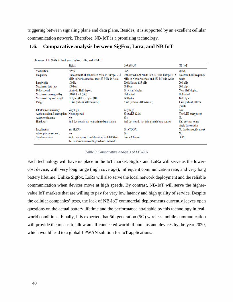
1.6. Comparative analysis between SigFox, Lora, and NB IoT
Table 3 Comparative analysis of LPWAN
Each technology will have its place in the IoT market. Sigfox and LoRa will serve as the lower-
cost device, with very long range (high coverage), infrequent communication rate, and very long
battery lifetime. Unlike Sigfox, LoRa will also serve the local network deployment and the reliable
communication when devices move at high speeds. By contrast, NB-IoT will serve the higher-
value IoT markets that are willing to pay for very low latency and high quality of service. Despite
the cellular companies’ tests, the lack of NB-IoT commercial deployments currently leaves open
questions on the actual battery lifetime and the performance attainable by this technology in real-
world conditions. Finally, it is expected that 5th generation (5G) wireless mobile communication
will provide the means to allow an all-connected world of humans and devices by the year 2020,
which would lead to a global LPWAN solution for IoT applications.
41
Chapter 2: Narrow Band Internet of Things Voice services and mobile broadband services have been the sole focus of cellular broadband
networks for years. Over the years, thorough research and extensive studies has led to Machine-
Type Communication to become an integral part of the modern 5G network.
Initial works constituting from Release 8 to Release 11 dealt with numbering and addressing of
resource shortage during synchronous access of numerous terminals to the network, the signaling
planes as well as the dilemmas faced with the overload and congestion of data. Following up in
Release 12 improvements were made in the network system architecture that enhanced the security
as well as further improved the quality of low-cost MTC terminals. Release 13 of 3GPP brought
forward 3 new kind of NB air interfaces including GSM-compatible EC-GSM-IoT, LTE-
compatible eMTC and brand-new NB-IoT technology. Moreover, Release 13 focused on some
core properties of the MTC and these included improved indoor coverage, support for a massive
number of low throughput devices, low delay sensitivity, ultra-low device cost, low device power
consumption, optimized network architecture. Release 13 has laid the foundation ascertaining the
scopes for long-term works of improvement of NB-IoT. Crafted to the needs of using small
powered batteries, Release 14 has introduced a lower power class of 14 dBm instead of 23 dBm
used previously for NB-IoT. devices. New specifications also increase the size of the transport
blocks allowing the data to be broken into larger data packages reducing the time needed, directly
affecting the power consumption. 3GPP Release 14 brings enhancements in the cell capacity and
usage of NB‑IoT network resources via two features called Non‑Anchor Paging and Non‑Anchor
Random Access Procedure (RACH), increasing the number of devices to be operated in a single
network, like smart homes and connected building applications. LTE‑M significantly increases
data rates by expanding data packet sizes almost threefold. With peak data rates around 4 Mbps in
DL and 7 Mbps in UL at a bandwidth of 5 MHz, LTE‑M becomes an interesting technology for a
greater range of applications that require greater data throughput or lower latency, like in smart
cities and remote monitoring devices. RRC connection reestablishment allows modems to move
from one network cell to another without requiring to renegotiate a new connection.
3GPP Release 15 performed 5G self-evaluation of LTE-M and NB-IoT performance that showed

42
5G connection density requirement of a million devices per square kilometer with a service latency
of at most 10 seconds. Extremely low SNR levels can be sustained, a coupling loss of 164 dB
between the base station and the device is found which matches the 5G coverage requirements.
Massive IoT performance combination with eMBB and Critical IoT use cases must be supported
by mobile operators and consequently, R15 supports a close coexistence between NR, LTE-M and
NB-IoT allowing them to operate in the same frequency band, configure the same physical layer
numerology, align the uplink and downlink transmissions in time and frequency and reserve NR
time-frequency resources dedicated for LTE-M and NB-IoT transmissions.
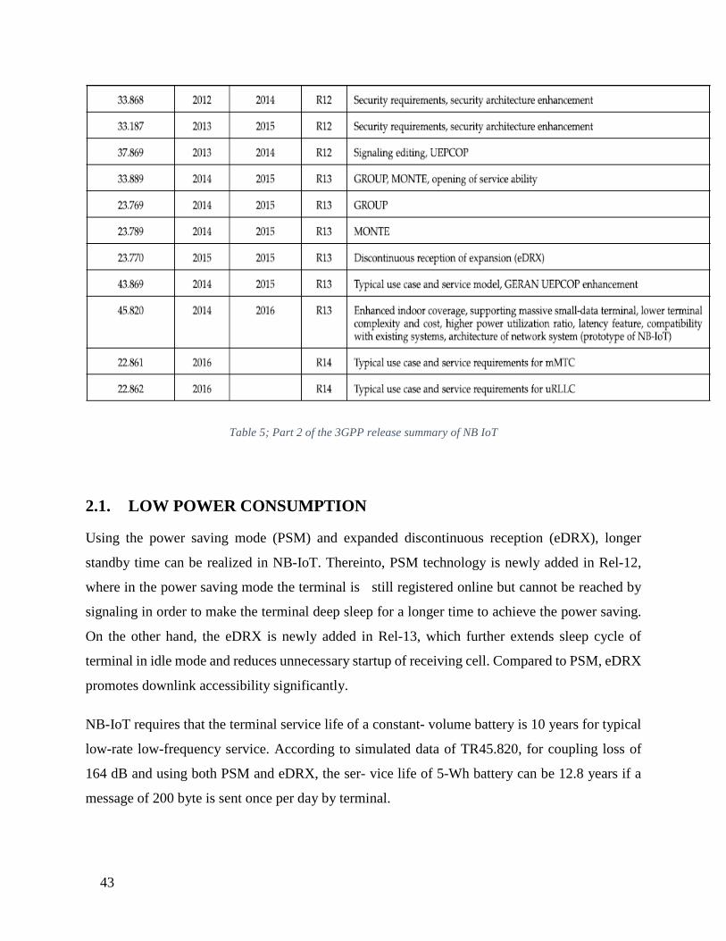
Table 4 Part 1 of the 3GPP release summary of NB IoT
43
Table 5; Part 2 of the 3GPP release summary of NB IoT
2.1. LOW POWER CONSUMPTION
Using the power saving mode (PSM) and expanded discontinuous reception (eDRX), longer
standby time can be realized in NB-IoT. Thereinto, PSM technology is newly added in Rel-12,
where in the power saving mode the terminal is still registered online but cannot be reached by
signaling in order to make the terminal deep sleep for a longer time to achieve the power saving.
On the other hand, the eDRX is newly added in Rel-13, which further extends sleep cycle of
terminal in idle mode and reduces unnecessary startup of receiving cell. Compared to PSM, eDRX
promotes downlink accessibility significantly.
NB-IoT requires that the terminal service life of a constant- volume battery is 10 years for typical
low-rate low-frequency service. According to simulated data of TR45.820, for coupling loss of
164 dB and using both PSM and eDRX, the ser- vice life of 5-Wh battery can be 12.8 years if a
message of 200 byte is sent once per day by terminal.
44
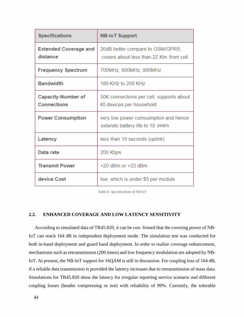
Table 6: Specifications of NB IoT
2.2. ENHANCED COVERAGE AND LOW LATENCY SENSITIVITY
According to simulated data of TR45.820, it can be con- firmed that the covering power of NB-
IoT can reach 164 dB in independent deployment mode. The simulation test was conducted for
both in-band deployment and guard band deployment. In order to realize coverage enhancement,
mechanisms such as retransmission (200 times) and low frequency modulation are adopted by NB-
IoT. At present, the NB-IoT support for 16QAM is still in discussion. For coupling loss of 164 dB,
if a reliable data transmission is provided the latency increases due to retransmission of mass data.
Simulations for TR45.820 show the latency for irregular reporting service scenario and different
coupling losses (header compressing or not) with reliability of 99%. Currently, the tolerable

45
latency in 3GPP IoT is 10 s. In fact, lower latency of about 6 s for maximal coupling losses can be
also supported. For more details, please refer to simulation results of NB-IoT for TR45.820.
2.3. TRANSMISSION MODE
The development of NB-IoT is based on LTE. The modification is mainly made on relevant
technologies of LTE according to NB-IoT unique features. The RF bandwidth of NB-IoT physical
layer is 200 kHz. In downlink, NB-IoT adopts QPSK modem and OFDMA technology with sub-
carrier spacing of 15 KHz [32]. In uplink, BPSK or QPSK modem and SC-FDMA technology
including single sub-carrier and multiple subcarrier are adopted. A single sub-carrier technology
with sub-carrier spacing of 3.75 kHz and 15 kHz is applicable to IoT terminal with ultra-low rate
and ultra-low power consumption.
For sub-carrier spacing of 15 kHz, 12 continuous sub- carriers are defined. Accordingly, 48
continuous sub-carriers are defined for sub-carrier spacing of 3.75 kHz. Multiple sub- carrier
transmission supports sub-carrier spacing of 15 kHz and defines 12 continuous sub-carriers which
are combined into 3, 6, or 12 continuous sub-carriers. The coverage abiliity for 3.75-kHz spacing
is higher than for 15-kHz spacing because of higher power spectral density. The cell capacity for
15-kHz spacing is 92% of that for 3.75-kHz spacing, but the dispatching efficiency and dispatching
complexity are superior. Since the Narrow Physical Random-Access Channel (NPRACH) has to
adopt single sub-carrier transmission with spacing of 3.75 kHz, most of equipment preferentially
supports single sub-carrier transmission with spacing of 3.75 kHz for uplink. After introducing
single sub- carrier transmission with spacing of 15 kHz and multiple sub- carrier transmission,
choice is made adaptively according to channel quality at terminal. The minimal dispatching unit
for the Narrow Physical Downlink Shared Channel (NPDSCH) transmission is the resource block
(RB), and the minimal dis- patching unit for the Narrow Physical Uplink Shared Channel
(NPUSCH) transmission is the resource unit (RU). In the aspect of time domain, for single sub-
carrier transmission, the resource unit is 32 ms for sub-carrier spacing of 3.75 kHz and 8 ms for
sub-carrier spacing of 15 kHz, and for multiple sub-carrier transmission, the resource unit is 4 ms
for spacing with 3 sub-carriers, 2 ms for spacing with 6 sub-carriers, and 1 ms for spacing with 12
sub-carriers.
46
The protocol of NB-IoT high layer (the layer above physical layer) is formulated through
modification of some LTE features, such as multi-connection, low power consumption and few
data. The core network of NB-IoT is connected through S1 interface.
2.4. SPECTRUM RESOURCE
The IoT is the core service that will attract larger user group on communication service market
in the future, therefore the development of NB-IoT has a great support from four largest telecom
operators in China, who own respective spectrum resource for NB-IoT.
2.5. WORKING MODE OF NB-IOT
According to stipulations in RP-151621 of NB-IoT, NB-IoT currently supports only FDD
transmission mode with bandwidth of 180 kHz and 3 following types of deployment scenes.
• Independent deployment (Stand-alone mode), which utilizes independent frequency band
that does not over- lap with the frequency band of LTE;
• Guard-band deployment (Guard-band mode), which utilizes edge frequency band of LTE;
• In-band deployment (In-band mode), which utilizes LTE frequency band for deployment,
and it takes 1 PRB of LTE frequency band resource for deployment
47
Chapter 3: Doppler Spread 3.1. What is Doppler Effect?
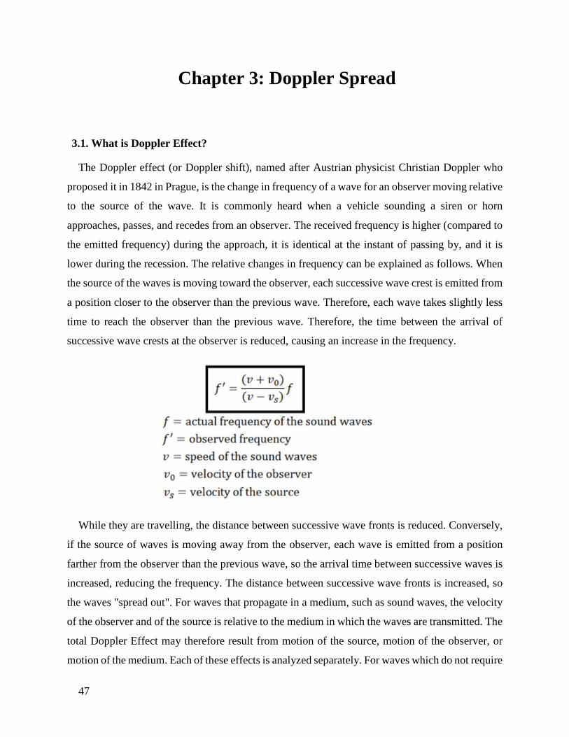
The Doppler effect (or Doppler shift), named after Austrian physicist Christian Doppler who
proposed it in 1842 in Prague, is the change in frequency of a wave for an observer moving relative
to the source of the wave. It is commonly heard when a vehicle sounding a siren or horn
approaches, passes, and recedes from an observer. The received frequency is higher (compared to
the emitted frequency) during the approach, it is identical at the instant of passing by, and it is
lower during the recession. The relative changes in frequency can be explained as follows. When
the source of the waves is moving toward the observer, each successive wave crest is emitted from
a position closer to the observer than the previous wave. Therefore, each wave takes slightly less
time to reach the observer than the previous wave. Therefore, the time between the arrival of
successive wave crests at the observer is reduced, causing an increase in the frequency.
While they are travelling, the distance between successive wave fronts is reduced. Conversely,
if the source of waves is moving away from the observer, each wave is emitted from a position
farther from the observer than the previous wave, so the arrival time between successive waves is
increased, reducing the frequency. The distance between successive wave fronts is increased, so
the waves "spread out". For waves that propagate in a medium, such as sound waves, the velocity
of the observer and of the source is relative to the medium in which the waves are transmitted. The
total Doppler Effect may therefore result from motion of the source, motion of the observer, or
motion of the medium. Each of these effects is analyzed separately. For waves which do not require
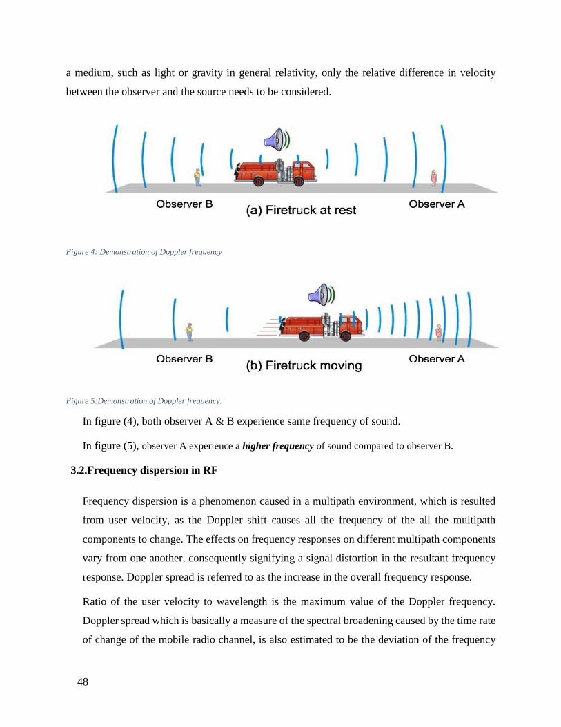
48
a medium, such as light or gravity in general relativity, only the relative difference in velocity
between the observer and the source needs to be considered.
Figure 4: Demonstration of Doppler frequency
Figure 5:Demonstration of Doppler frequency.
In figure (4), both observer A & B experience same frequency of sound.
In figure (5), observer A experience a higher frequency of sound compared to observer B.
3.2.Frequency dispersion in RF
Frequency dispersion is a phenomenon caused in a multipath environment, which is resulted
from user velocity, as the Doppler shift causes all the frequency of the all the multipath
components to change. The effects on frequency responses on different multipath components
vary from one another, consequently signifying a signal distortion in the resultant frequency
response. Doppler spread is referred to as the increase in the overall frequency response.
Ratio of the user velocity to wavelength is the maximum value of the Doppler frequency.
Doppler spread which is basically a measure of the spectral broadening caused by the time rate
of change of the mobile radio channel, is also estimated to be the deviation of the frequency
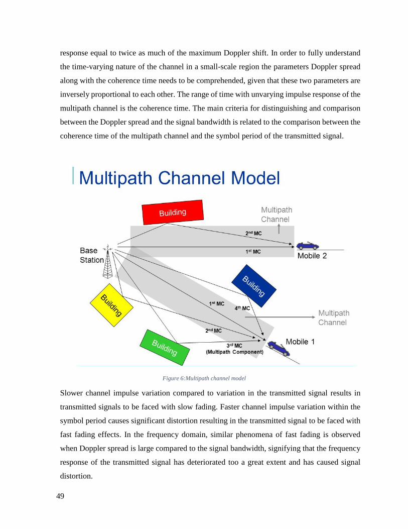
49
response equal to twice as much of the maximum Doppler shift. In order to fully understand
the time-varying nature of the channel in a small-scale region the parameters Doppler spread
along with the coherence time needs to be comprehended, given that these two parameters are
inversely proportional to each other. The range of time with unvarying impulse response of the
multipath channel is the coherence time. The main criteria for distinguishing and comparison
between the Doppler spread and the signal bandwidth is related to the comparison between the
coherence time of the multipath channel and the symbol period of the transmitted signal.
Figure 6:Multipath channel model
Slower channel impulse variation compared to variation in the transmitted signal results in
transmitted signals to be faced with slow fading. Faster channel impulse variation within the
symbol period causes significant distortion resulting in the transmitted signal to be faced with
fast fading effects. In the frequency domain, similar phenomena of fast fading is observed
when Doppler spread is large compared to the signal bandwidth, signifying that the frequency
response of the transmitted signal has deteriorated too a great extent and has caused signal
distortion.

50
3.1. Fading
Variation in the signal strength with respect to time as it is received at the antenna from the
transmitter at a distant end is addressed as fading. Multiple versions of the transmitted signal
arrive at the receiver at slightly different time instants. The multipath channel is time-varying
and it varies constantly with time. The variation is unpredictable to a great extent. The variation
occurs both due to change in the environment and due to movement of the UE. For devices
that are in mobility, the degrading performance is due to slow fading where signal paths change
due to shadowing and obstructions. The coherence time is very much greater than the symbol
period causing the impulse response changes to be much slower than the transmitted signal.
Equivalently in the frequency domain, the signal bandwidth is much greater compared to the
Doppler spread.
For objects placed in extremely remote locations, the devices are subject to fast fading resulting
from the effects of constructive and destructive interference patterns caused due to multipath.
Channel impulse response changes rapidly within the symbol duration. Considering the
frequency domain, the signal bandwidth is much smaller than the Doppler spread which
equivalently means that the symbol period is much smaller than the coherence time in the time
domain.
NB-IoT devices are presumed to be an integral part of the future when the full deployment of
5G is done, with about a million devices constantly communicating with each other in an area
as small as a square kilometer. There will be devices located in the basements and quite
obviously they will not be able to communicate with the transmitter with as much ease as the
devices in more convenient locations, and will be subject to fast fading problems. NB-IoT
devices are also seen to be found in high speed vehicles. While LTE can support high
performance for UE speeds up to 120 km/h but at speeds over 300 km/h or even 500 km/h, the
service is borderline sustained but quite close to unusable. Such NB-IoT devices can be found
in high speed bullet trains or similar vehicles. The dilemma faced in this case is the slow fading
phenomena.

51
3.2. Effect of Doppler frequency on NB IoT
For the purpose of analyzing the extent of the effects that these scenarios have on NB-IoT
devices, thorough simulations have been carried out that tested the performance variation of
these devices under different changing parameters. Uplink data transfer as well as the downlink
data transfer were tested under a perfect channel estimator which is a perfect MIMO channel
estimate after OFDM modulation. This is done by setting the channel with desired
configuration and sending a set of known symbols through it for each transmit antenna in turn.
A range of data sets have been collected showing results for uplink and downlink channels.
There are simulation results for throughput against Doppler frequency and block error rate
(BLER) against Doppler frequency. Throughput is how much data actually does travel through
the 'channel' successfully while BLER is a ratio of the number of erroneous blocks to the total
number of blocks transmitted. Simulation results were also obtained for throughput and BLER
against the signal-to-noise ratio (SNR).
Doppler frequency depends on carrier frequency and maintains a proportional relation with it
and maintains an inverse relation with the wavelength. Simulations help us to have a deeper
understanding of the change in performance. The performance analysis data is used to control
the carrier frequency via the cognitive radio. Cognitive radio is basically a software defined
radio that automatically detects the available channel and bandwidth vacancy. Cognitive radio
will be implemented in the base station where it senses the traffic and allocates it and then
routes it from one node to another. Moreover, the exponential increase in the number of devices
in the near future means that the cognitive radio will play a major role in the selection of
carriers.
The result obtained from the performance analysis is then analyzed under the algorithm and
the suitable carrier frequency is selected that is going to ensure a greater performance by the
NB-IoT devices.
52
Chapter 4: Cognitive Radio 4.1. Introduction:
A Cognitive Radio (CR) is a radio that can be programmed and configured dynamically to use the
best wireless channels in its vicinity to avoid user interference and congestion. Such a radio
automatically detects available channels in wireless spectrum, then accordingly changes
its transmission or reception parameters to allow more concurrent wireless communications in a
given spectrum band at one location. This process is a form of dynamic spectrum management. In
this process communication systems are aware of their internal state and environment, such as
location and utilization on RF frequency spectrum at that location. They can make decisions about
their radio operating behavior by mapping that information against predefined objectives. It also
has the capability of learning waveforms and protocols, to adapt to the local spectrum availability
and to learn the current needs of its user.
4.2. HISTORY
The concept of cognitive radio was first proposed by Joseph Mitola III in a seminar at KTH (the
Royal Institute of Technology in Stockholm) in 1998 and published in an article by Mitola and
Gerald Q. Maguire, Jr. in 1999. It was a novel approach in wireless communications, which Mitola
later described as: The point in which wireless personal digital assistants (PDAs) and the related
networks are sufficiently computationally intelligent about radio resources and related computer-
to-computer communications to detect user communications needs as a function of use context,
and to provide radio resources and wireless services most appropriate to those needs. Cognitive
radio is considered as a goal towards which a software-defined radio platform should evolve: a
fully reconfigurable wireless transceiver which automatically adapts its communication
parameters to network and user demands. Traditional regulatory structures have been built for an
analog model and are not optimized for cognitive radio. Regulatory bodies in the world (including
the Federal Communications Commission in the United States and Ofcom in the United Kingdom)
as well as different independent measurement campaigns found that most radio frequency
spectrum was inefficiently utilized. Cellular network bands are overloaded in most parts of the
world, but other frequency bands (such as military, amateur radio and paging frequencies) are
53
insufficiently utilized. Independent studies performed in some countries confirmed that
observation, and concluded that spectrum utilization depends on time and place. Moreover, fixed
spectrum allocation prevents rarely used frequencies (those assigned to specific services) from
being used, even when any unlicensed users would not cause noticeable interference to the
assigned service. Regulatory bodies in the world have been considering whether to allow
unlicensed users in licensed bands if they would not cause any interference to licensed users. These
initiatives have focused cognitive-radio research on dynamic spectrum access.
The first cognitive radio wireless regional area network standard, IEEE 802.22, was developed by
IEEE 802 LAN/MAN Standard Committee (LMSC)[3] and published in 2011. This standard uses
geolocation and spectrum sensing for spectral awareness. Geolocation combines with a database
of licensed transmitters in the area to identify available channels for use by the cognitive radio
network. Spectrum sensing observes the spectrum and identifies occupied channels. IEEE 802.22
was designed to utilize the unused frequencies or fragments of time in a location. This white space
is unused television channels in the geolocated areas. However, cognitive radio cannot occupy the
same unused space all the time. As spectrum availability changes, the network adapts to prevent
interference with licensed transmissions.
4.3. Functions:
The main functions of cognitive radio system include power control, spectrum sensing and
spectrum management. Power control is used so that the capacity of the secondary users is
maximized along with applying certain constraints to protect the primary users. A cognitive radio
can sense empty spectrum without causing any form of interference to other users. There are three
spectrum-sensing techniques:
• Power Control: Power control is usually used for spectrum sharing CR systems to
maximize the capacity of secondary users with interference power constraints to protect
the primary users.
• Spectrum sensing: Detecting unused spectrum and sharing it, without harmful interference
to other users; an important requirement of the cognitive-radio network is to sense empty
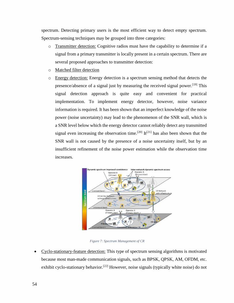
54
spectrum. Detecting primary users is the most efficient way to detect empty spectrum.
Spectrum-sensing techniques may be grouped into three categories:
o Transmitter detection: Cognitive radios must have the capability to determine if a
signal from a primary transmitter is locally present in a certain spectrum. There are
several proposed approaches to transmitter detection:
o Matched filter detection
o Energy detection: Energy detection is a spectrum sensing method that detects the
presence/absence of a signal just by measuring the received signal power.[19] This
signal detection approach is quite easy and convenient for practical
implementation. To implement energy detector, however, noise variance
information is required. It has been shown that an imperfect knowledge of the noise
power (noise uncertainty) may lead to the phenomenon of the SNR wall, which is
a SNR level below which the energy detector cannot reliably detect any transmitted
signal even increasing the observation time.[20] It[21] has also been shown that the
SNR wall is not caused by the presence of a noise uncertainty itself, but by an
insufficient refinement of the noise power estimation while the observation time
increases.
Figure 7: Spectrum Management of CR
• Cyclo-stationary-feature detection: This type of spectrum sensing algorithms is motivated
because most man-made communication signals, such as BPSK, QPSK, AM, OFDM, etc.
exhibit cyclo-stationary behavior.[22] However, noise signals (typically white noise) do not

55
exhibit cyclo-stationary behavior. These detectors are robust against noise variance
uncertainty. The aim of such detectors is to exploit the cyclo-stationary nature of man-
made communication signals buried in noise. Their main decision parameter is comparing
the non-zero values obtained by CSD of the primary signal. Cyclo-stationary detectors can
be either single cycle or multicycle cyclo-stationary.
• Wideband spectrum sensing: refers to spectrum sensing over large spectral bandwidth,
typically hundreds of MHz or even several GHz. Since current ADC technology cannot
afford the high sampling rate with high resolution, it requires revolution techniques, e.g.,
compressive sensing and sub-Nyquist sampling.[24]
• Cooperative detection: Refers to spectrum-sensing methods where information from
multiple cognitive-radio users is incorporated for primary-user detection
• Interference-based detection
• Null-space based CR: With the aid of multiple antennas, CR detects the null-space of the
primary-user and then transmits within the null-space, such that its subsequent transmission
causes less interference to the primary-user
• Spectrum management: Capturing the best available spectrum to meet user communication
requirements, while not creating undue interference to other (primary) users. Cognitive
radios should decide on the best spectrum band (of all bands available) to meet quality of
service requirements; therefore, spectrum-management functions are required for cognitive
radios. Spectrum-management functions are classified as:
• Spectrum analysis
• Spectrum decision
The practical implementation of spectrum-management functions is a complex and multifaceted
issue, since it must address a variety of technical and legal requirements. An example of the former
is choosing an appropriate sensing threshold to detect other users, while the latter is exemplified
by the need to meet the rules and regulations set out for radio spectrum access in international
(ITU radio regulations) and national (telecommunications law) legislation.
56
4.4. Application
• The application of CR networks to emergency and public safety communications by
utilizing white space
• The potential of CR networks for executing dynamic spectrum access (DSA)
• Application of CR networks to military action such as chemical biological radiological and
nuclear attack detection and investigation, command control, obtaining information of
battle damage evaluations, battlefield surveillance, intelligence assistance, and
targeting.[34]
• They are also proven to be helpful in establishing Medical Body Area Networks which can
be utilized in omnipresent patient monitoring that aids in immediately notifying the doctors
regarding vital information of patients such as sugar level, blood pressure, blood oxygen
and electrocardiogram (ECG), etc. This gives the additional advantage of reducing the risk
of infections and also increases the patient's mobility.
4.5. Advantages:
Cognitive radio system uses the spectrum efficiently. For utilizing the radio bands in a country, a
license is required from the government. This is a costly procedure. There are certain licensed
spectrum bands that are underutilized and unutilized. Cognitive radio can utilize this spectrum and
license holders are also not disturbed. This unutilized spectrum is known as white space.
In a traditional wireless sensor network, a single channel is used for communication. When an
event is detected, the sensor nodes generate packets. In a dense network, sensor nodes try to occupy
the single communication channel at the same time. This increases the possibility of collisions and
the communication quality is decreased. Moreover, there is more power consumption and packet
delay. Cognitive radio gives the opportunity to utilize multiple channels thereby reducing the
chances of collision and also increases the communication quality. Cognitive Radio is used in
various military and public services like chemical, biological and nuclear radiation detection, war
surveillance etc. Traditional wireless sensor networks face the problem of signal jam. But this
problem is no longer exist if we use cognitive radio wireless sensor network. Cognitive Radio can
handoff a wide range of frequencies. It is also useful when the applications need large bandwidth.

57
1.Overcome radio spectrum density
By sensing spectrum utilization (irrespective of channel allocation), cognitive radios can broadcast
on unused radio spectrum, while still avoiding interference with the operation of the primary
licensee.
2. Avoid intentional radio jamming scenarios
By sensing channel availability and even predicting the jammer’s tactics , cognitive radios can
evade jamming by dynamically and preemptively switching to higher quality channels.
3. Switch to power saving protocol
By switching to protocols that trade off lower power consumption for lower bandwidth, cognitive
radios conserve power when slower data rates suffice.
4. Improve satellite communications
How? By predicting rain fade and reconfiguring transmitters/receivers for optimum bandwidth,
cognitive radios improve communication quality when and where the information is needed most.
5. Improves quality of service (QoS)
4.6. Cognitive Radio and NB-IOT:
The increased popularity and urgency to accommodate a huge amount of IOT devices with a highly
efficient network has led us to further analyze the performance paradigm of one of these
technologies called Narrow band Internet of things and introduce the idea of cognitive radio in
NB- IOT. This proposal aims to solve the spectrum shortage and improve resource allocation for
the huge data traffic.
So, we are merging NB-IOT with Cognitive Radio. So, the CR will sense the vacancy in the
frequency band and shift the carrier for spectrum efficiency
Due to doppler spreading out SNR increases so throughput decreases as it is inversely proportional
to SNR. So, we need to find out which carrier frequency will be suitable for different situations
give high spectrum efficiency and spectrum management will reduce the amount of waste will be
decided by the intelligence system that is cognitive radio.
It will measure the throughput and BLER with a periodic interval. If the value falls below the
threshold value for minimum criteria of good SNR it will search for the required carrier frequency
available in the white space and band hole and with the routing technique it will adapt with the
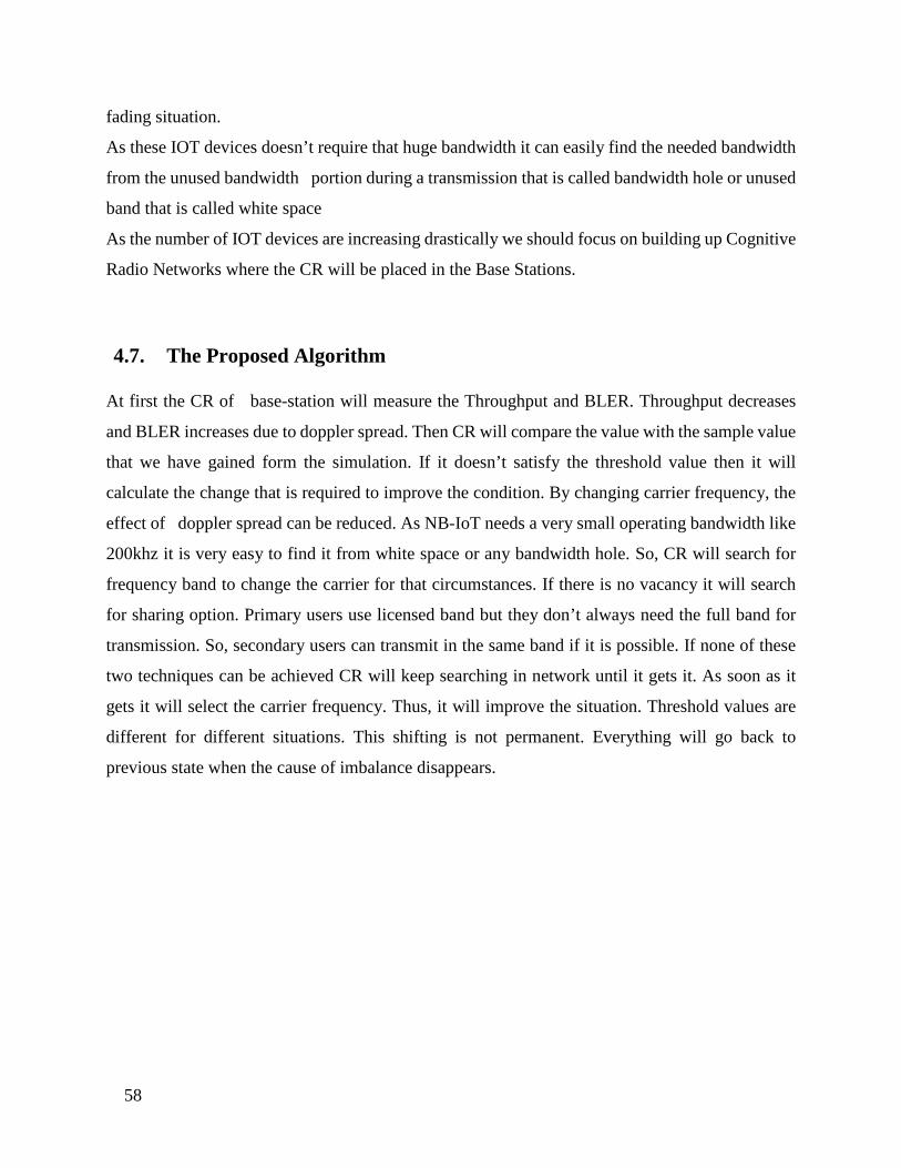
58
fading situation.
As these IOT devices doesn’t require that huge bandwidth it can easily find the needed bandwidth
from the unused bandwidth portion during a transmission that is called bandwidth hole or unused
band that is called white space
As the number of IOT devices are increasing drastically we should focus on building up Cognitive
Radio Networks where the CR will be placed in the Base Stations.
4.7. The Proposed Algorithm
At first the CR of base-station will measure the Throughput and BLER. Throughput decreases
and BLER increases due to doppler spread. Then CR will compare the value with the sample value
that we have gained form the simulation. If it doesn’t satisfy the threshold value then it will
calculate the change that is required to improve the condition. By changing carrier frequency, the
effect of doppler spread can be reduced. As NB-IoT needs a very small operating bandwidth like
200khz it is very easy to find it from white space or any bandwidth hole. So, CR will search for
frequency band to change the carrier for that circumstances. If there is no vacancy it will search
for sharing option. Primary users use licensed band but they don’t always need the full band for
transmission. So, secondary users can transmit in the same band if it is possible. If none of these
two techniques can be achieved CR will keep searching in network until it gets it. As soon as it
gets it will select the carrier frequency. Thus, it will improve the situation. Threshold values are
different for different situations. This shifting is not permanent. Everything will go back to
previous state when the cause of imbalance disappears.
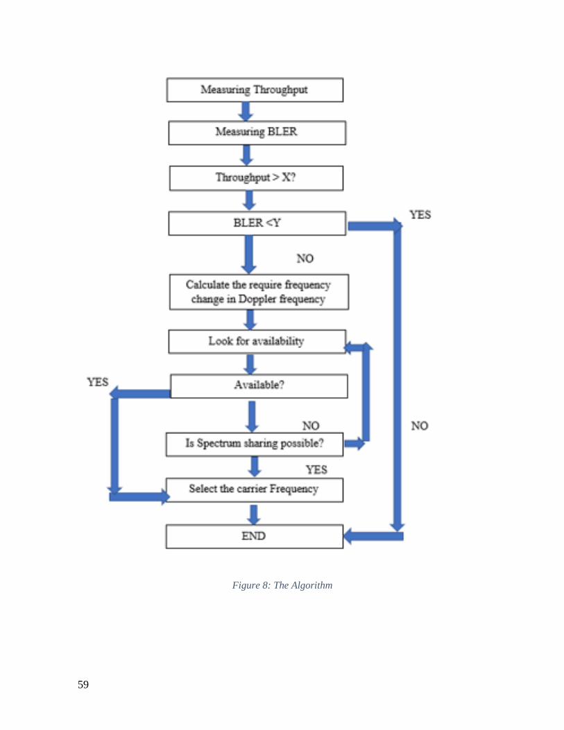
59
Figure 8: The Algorithm

60
Chapter 5: Simulation and Result Analysis
5.1: Simulation parameters
In order to establish the problem statement of this proposal we scrutinized the effect of doppler
spread on the performance of NB IOT. The simulation was originally carried out to calculate the
percentage throughput and block error rate (BLER) of both NB-IoT Narrowband Physical
Downlink Shared Channel (NPDSCH) and NB IoT Narrowband Uplink Shared Channel
(NPUSCH) under frequency selective fading and Additive White Gaussian Noise (AWGN)
channel for a range of signal to noise ratio (SNR) at a particular doppler frequency. All the relevant
parameters used to model this simulation are recorded in table 1. Keeping all other channel
parameters constant, we changed the doppler frequency from 1000 Hz to 3000 Hz at 500 Hz
interval. The frequency range was selected after an approximate calculation of relative speed with
carrier frequency from equation (1)
𝑓𝑓𝑓𝑓 =𝑣𝑣𝜆𝜆
cos(𝜃𝜃) (1)
Where the fd is the doppler frequency and v is the relative speed of the UE, 𝜃𝜃 is the angle between
the base station and UE and 𝜆𝜆 is the wavelength of the carrier frequency.
If we approximate carrier frequency to be about 1800 MHz and 𝜃𝜃 to be 0 or 180 degree than from
the equation (1) we get a doppler frequency of 1000 Hz for corresponding speed of 160 m/s. This
is our lower limit speed and for the higher limit we took a speed of 500 m/s, the speed of a bullet
train, which gives a corresponding doppler frequency of 3000 Hz.
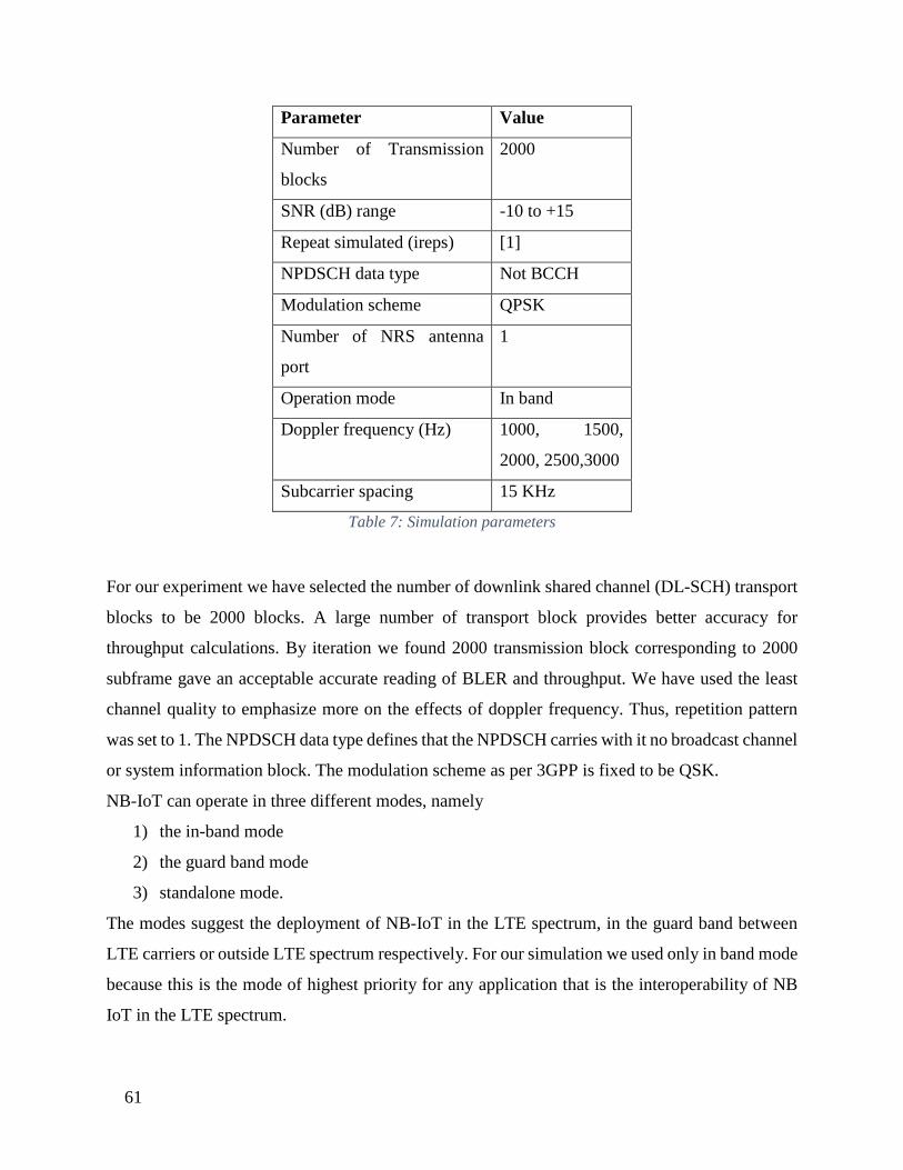
61
Parameter Value
Number of Transmission
blocks
2000
SNR (dB) range -10 to +15
Repeat simulated (ireps) [1]
NPDSCH data type Not BCCH
Modulation scheme QPSK
Number of NRS antenna
port
1
Operation mode In band
Doppler frequency (Hz) 1000, 1500,
2000, 2500,3000
Subcarrier spacing 15 KHz
Table 7: Simulation parameters
For our experiment we have selected the number of downlink shared channel (DL-SCH) transport
blocks to be 2000 blocks. A large number of transport block provides better accuracy for
throughput calculations. By iteration we found 2000 transmission block corresponding to 2000
subframe gave an acceptable accurate reading of BLER and throughput. We have used the least
channel quality to emphasize more on the effects of doppler frequency. Thus, repetition pattern
was set to 1. The NPDSCH data type defines that the NPDSCH carries with it no broadcast channel
or system information block. The modulation scheme as per 3GPP is fixed to be QSK.
NB-IoT can operate in three different modes, namely
1) the in-band mode
2) the guard band mode
3) standalone mode.
The modes suggest the deployment of NB-IoT in the LTE spectrum, in the guard band between
LTE carriers or outside LTE spectrum respectively. For our simulation we used only in band mode
because this is the mode of highest priority for any application that is the interoperability of NB
IoT in the LTE spectrum.
62
Figure 9: Modes of Operation of NB IoT
For the downlink model we generated a random stream of bits corresponding to the number of
transport block upon which we implied CRC encoding, convolutional encoding and rate matching
and produced NPDSCH bits. These bits are converted to symbols by Scrambling, modulation,
layer mapping and precoding. The symbols are then OFDM modulated to create a time domain
waveform. The waveform is transmitted through a preconfigured fading channel with additive
white gaussian noise (AWGN) added. At the receiver end the transmitted waveform is
synchronized and demodulated using perfect channel estimation which provides a perfect MIMO
channel estimate after OFDM modulation. For every point of SNR, the block error rate and
percentage throughput are calculated and stored.
For the uplink model a similar process is used except a SC- FDMA modulation is used. All the
other parameters are kept constant to produce a reliable data set. With our simulation we produced
two data sets, uplink and downlink. Each data set consists of throughput and BLER for different
SNR at different Doppler frequency.

63
5.2 Simulation results for uplink signal
The data sets collected are used to plot the following graphs
1) Throughput vs SNR
2) BLER vs SNR
The data set:
Table 8: Data set for Uplink Simulations
The Plots These graphs help to demonstrate how the throughput and BLER varies for the range of SNR
values used at different Doppler frequency used. The graphs plotted will also help to understand
by how much the BLER and throughput varies for when Doppler frequency increases. This result
will be fed to cognitive radio for analysis

64
Figure 10: Throughput vs SNR for different Doppler frequency
Figure 11 BLER vs SNR for different Doppler Frequency

65
5.3: Performance analysis of Uplink signal
In order to find out by how much the Doppler frequency causes the throughput and BLER to
change and better understand their relationship, the data sheets collected is further used to plot
graphs of the following:
1) Throughput vs Doppler frequency
2) BLER vs Doppler frequency
SNR values used: 5db, 10db & 15db
The data sets
Table 9: Data sets for UL SNR vs Doppler frequency
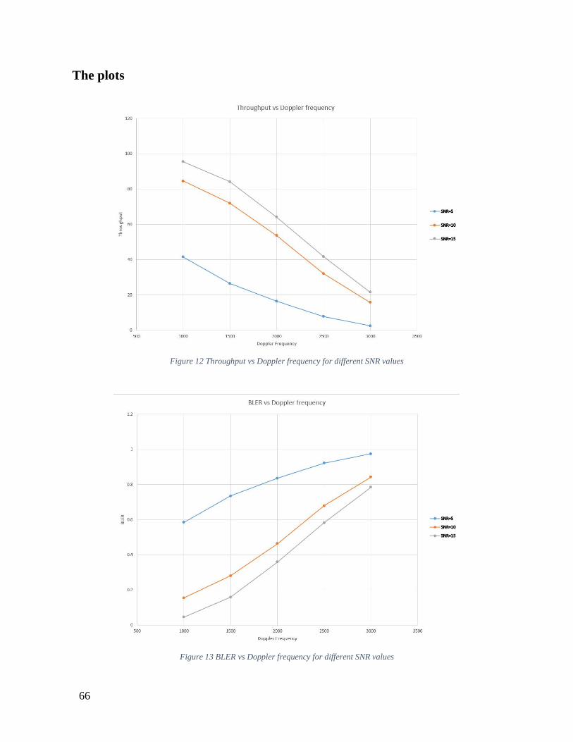
66
The plots
Figure 12 Throughput vs Doppler frequency for different SNR values
Figure 13 BLER vs Doppler frequency for different SNR values
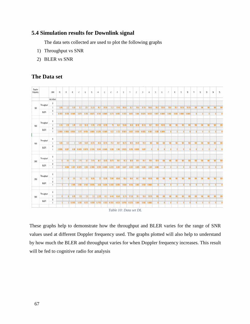
67
5.4 Simulation results for Downlink signal The data sets collected are used to plot the following graphs
1) Throughput vs SNR
2) BLER vs SNR
The Data set
Table 10: Data set DL
These graphs help to demonstrate how the throughput and BLER varies for the range of SNR
values used at different Doppler frequency used. The graphs plotted will also help to understand
by how much the BLER and throughput varies for when Doppler frequency increases. This result
will be fed to cognitive radio for analysis
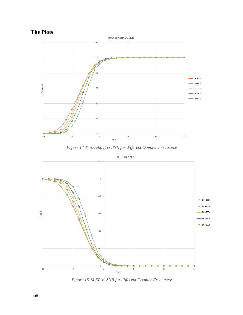
68
The Plots
Figure 14 Throughput vs SNR for different Doppler Frequency
Figure 15 BLER vs SNR for different Doppler Frequency
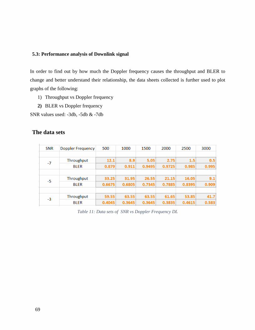
69
5.3: Performance analysis of Downlink signal
In order to find out by how much the Doppler frequency causes the throughput and BLER to
change and better understand their relationship, the data sheets collected is further used to plot
graphs of the following:
1) Throughput vs Doppler frequency
2) BLER vs Doppler frequency
SNR values used: -3db, -5db & -7db
The data sets
Table 11: Data sets of SNR vs Doppler Frequency DL
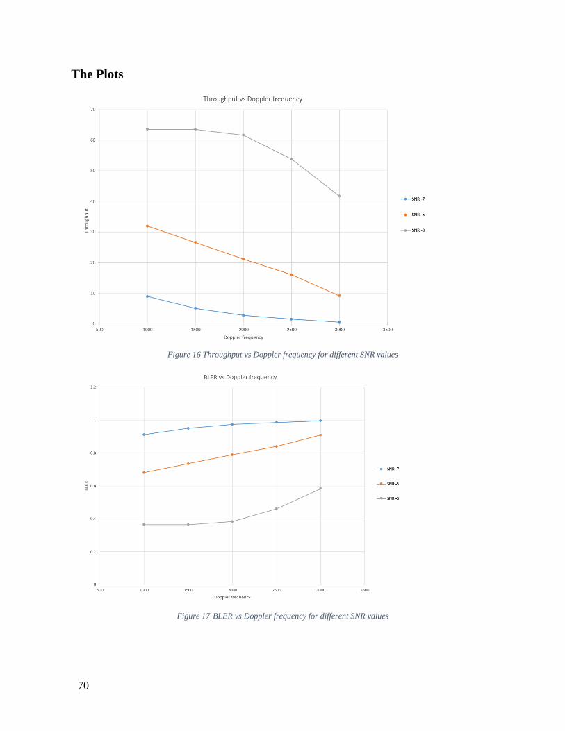
70
The Plots
Figure 16 Throughput vs Doppler frequency for different SNR values
Figure 17 BLER vs Doppler frequency for different SNR values

71
Chapter 6: Conclusion and Future reference 6.1. Book Summary
Due to increased popularity of IoT devices and applications it is safe to say that in the near
future telecommunication engineers will have to accommodate the massive amount of data traffic
within the bounds of the limited available radio resources. All the popular Low Power Wide Area
Network (LPWAN) discussed earlier, viz SigFox, LoRa, NB-IoT, are developed in an effort to
cope with this new era of IoT devices. While SigFox and LoRa operate in the unlicensed band,
NB – IoT operates in the licensed spectrum. Thus, it provides a wider network coverage along
with other benefits. Furthermore, it can be extrapolated that NB-IoT will engulf the lion share of
the IoT market.
Also, one of the primary reasons of the preference of NB IoT is its international standard set by
3GPP. The performance analysis conducted implicates of an underlying problem. For devices that
are in mobility, the performance of the signal degrades due to slow fading where signal paths
change due to shadowing and obstructions. The results of the performance analysis clearly show
the degradation of network due to doppler effect which in turn is linked with the mobility of the
device.
In conclusion the adaptive carrier based on channel estimation promises a significant
performance enhancement for NB IoT. Cognitive radio theoretically supports this theory. The
simulation results not only show the relation between doppler spread and performance of NB IoT
but also forges this idea and predicting the extent to which cognitive radio can be used to enhance
the performance.
Cognitive radio provides a cutting-edge solution to the problem of spectrum crunch and
represents a new paradigm for designing intelligent wireless networks to mitigate the spectrum
scarcity problem and provide significant gain in spectrum efficiency. We anticipate that cognitive
radio technology will soon emerge from early stage laboratory trials and vertical applications with
regard to a theoretical approach and emerge as a multi-purpose spectrum stretching programmable
72
radio that will serve as a universal platform for wireless system development, much like
microprocessors have served a similar role for computation. There is however a big gap between
having a flexible cognitive radio, effectively a building block, and the large-scale deployment of
cognitive radio networks that dynamically optimize spectrum use. Building and deploying a
network of cognitive radios is a complex task. Major research themes being pursued include
spectrum policy alternatives, system models, and spectrum sensing algorithms, cognitive radio
architecture as software abstractions, cooperative wireless communications, DSA technology,
Protocol architectures for CRNs (Cognitive Radio Networks), and algorithms for network security
for CRNs etc. CRN research must be relatable to the physical world and it is more than important
to test the same for real-world situations. Radios work. A CRN research program must develop
the tools and techniques to easily move information from field experiments (test beds) to abstract
models that confirm to real life issues and move questions from the models to experiments in the
field. A range of capabilities such as a flexible physical platform that supports diverse front-ends
and a range of programming tools is required. First, experimental platforms are required to gather
physical world experience specific to a certain situation and gather measurements in the real-world
platform that deploys the cognitive radio technology. Secondly, the arrangement should allow the
experiments to be repeated. Third, we need techniques to abstract field experiment measurements
into simpler models. This enables us to consider larger CRN systems before extensive deployment.
6.2. Future Plans:
In the future we plan to extend our research and create a prototype of the cognitive radio. In
order to completely establish the proposed theories, we have laid a plan.
First, we will need to simulate and carry the performance analysis of the change in doppler
frequency with carrier frequencies.
Secondly, we need to start the hardware phase which involves design phase, simulation and
finally implementation.
Finally, the prototype should be used to carry the real time performance analysis of the cognitive
radio-based carrier adaptation of NB IoT.

73
References
[1] Mohammad T. Kawser, “LTE Air Interface Protocols”, Artech House, Boston, USA (2011). ISBN: 978-1-
60807-201-9
[2] Alberto Rico-Alvariño, Madhavan Vajapeyam, Hao Xu, Xiaofeng Wang, Yufei Blankenship, Johan Bergman,
Tuomas Tirronen, and Emre Yavuz,” An Overview of 3GPP Enhancements on Machine to Machine
Communications”.
[3] Kais Mekkia,∗, Eddy Bajica, Frederic Chaxela, Fernand Meyerb,” A comparative study of LPWAN
technologies for large-scale IoT deployment”.
[4] Sergio Martiradonna, Alessandro Grassi, Giuseppe Piro, Luigi Alfredo Grieco, and Gennaro Boggia,”An open
source platform for exploring NB-IoT system performance”.
[5] Benny Vejlgaard1, Mads Lauridsen1, Huan Nguyen1, Istv´an Z. Kov´acs2, Preben Mogensen1,2, Mads
Sørensen, “Coverage and Capacity Analysis of Sigfox, LoRa, GPRS, and NB-IoT”.
[6] MIN CHEN1,2, (Senior Member, IEEE), YIMING MIAO1, YIXUE HAO1, (Senior Member, IEEE), AND
KAI HWANG3, (Life Fellow, IEEE),” Narrow Band Internet of Things”.
[7] Luca Feltrin, Galini Tsoukaneri, Massimo Condoluci, Chiara Buratti, Toktam Mahmoodi, Mischa Dohler, and
Roberto Verdone “Narrowband IoT: A Survey on Downlink and Uplink Perspectives”.
[8] [9] J. Schlienz and D. Raddino, “Narrowband Internet ofThings,” White Paper, Aug. 2016. R. Ratasuk et al.,
“Overview of Narrowband IoT in LTE Rel-13,” 2016 IEEE Conf. Standards for Commun. and Networking,
Oct. 2016, pp. 1–7.
[9] [ N. Mangalvedhe, R. Ratasuk, and A. Ghosh, “NB-IoT Deployment Study for Low Power Wide Area Cellular
IoT,” 2016 IEEE 27th Annual Int’l. Symp. Personal, Indoor, and Mobile Radio Commun., Sept 2016, pp. 1–6.
[10] A. Adhikary, X. Lin, and Y. P. E. Wang, “Performance Evaluation of NB-IoT Coverage,” 2016 IEEE VTC-
Fall, Sept 2016, pp. 1–5.
[11] 3GPP TS 23.682, “Architecture Enhancements to Facilitate Communications with Packet Data Networks and
Applications,” 2017; https://portal.3gpp.org.
[12] GSMA, “NB-IoT Deployment Guide to Basic Feature Set Requirements,” White Paper, Aug. 2017.
[13] GSMA, “3GPP Low Power Wide Area Technologies,GSMA White Paper,” tech. rep., Oct. 2016.
[14] 3GPP TS 37.868, “Study on RAN Improvements for Machinetype Communications,” 2017;
https://portal.3gpp.org.
[15] Y. D. Beyene et al., “On the Performance of Narrow-Band Internet of Things (NB-IoT),” 2017 IEEE Wireless
Communication and Networking Conf., Mar. 2017, pp. 1–6.
[16] Cellular networks for massive IoT-enabling low power wide area applications, white paper, 2016. Ericsson.
[Online]. Available: {https://www.ericsson.com/res/docs/whitepapers/wp iot.pdf}

74
[17] Visual Network Index (VNI) Complete Forecast Highlights, 2016. Cisco. [Online].
Available:{http://www.cisco.com/c/dam/m/en us/solutions/service-provider/vni-forecast-highlights/pdf/Global
2020 Forecast Highlights.pdf}
[18] J. Pet¨aj¨aj¨arvi, K. Mikhaylov, M. H¨am¨al¨ainen, and J. Iinatti, “Evaluation of LoRa LPWAN technology for
remote health and wellbeing monitoring,”in 2016 10th International Symposium on Medical Information and
Communication Technology (ISMICT), March 2016, pp. 1–5.
[19] Sigfox. [Online]. Available: https://www.lora-alliance.org
[20] T. Adame, A. Bel, B. Bellalta, J. Barcelo, and M. Oliver, “IEEE802.11AH: the WiFi approach for M2M
communications,” IEEE Wireless
Communications, vol. 21, no. 6, pp. 144–152, December 2014. New Work Item: NarrowBand IOT (NB-IOT).
TSG RAN Meeting #69, 2015. 3GPP. [Online]. Available: {www.3gpp.org/FTP/tsg ran/TSGRAN/TSGR
69/Docs/RP-151621.zip}
[21] New Study Item on Cellular System Support for Ultra Low Complexityand Low Throughput Internet of
Things. TSG-GERAN Meeting #62,2015. 3GPP. [Online]. Available: {http://www.3gpp.org/ftp/tsg geran/TSG
GERAN/GERAN 62 Valencia/Docs/GP-140421.zip}TS 36.211 Evolved Universal Terrestrial Radio Access (E-
UTRA) physical channels and modulation (Release 13), 2016. 3GPP. [Online]. Available:
{http://www.3gpp.org/ftp/specs/archive/23 series/23.060/23060-3c0.zip}
[22] TS 36.213 Evolved Universal Terrestrial Radio Access (EUTRA); Physical layer procedures (Release 13),
2016. 3GPP.[Online]. Available: {http://www.3gpp.org/ftp//Specs/archive/36 series/36.213/36213-d20.zip}TS
36.321 Evolved Universal Terrestrial Radio Access (E-UTRA); Medium Access Control (MAC) protocol
specification (Release 13), 2016. 3GPP. [Online]. Available: {http://www.3gpp.org/ftp//Specs/archive/36
series/36.321/36321-d20.zip}
[23] Aalto University, “Researchers implemented a prototype for Narrowband Internet-of-Things system,” Press
Release, 28 June 2016. [Online]. Available: {http://elec.aalto.fi/en/current/news/2016-06-28/}
[24] Ettus research, August 2016. [Online]. Available: http://ettus.com
[25] USRP X300 and X310 Spec Sheet, 2016. Ettus Research. [Online]. Available:
{https://www.ettus.com/content/files/X300 X310Spec Sheet.pdf}
[26] Z. Dawy et al., “Toward Massive Machine Type Cellular Communications,” IEEE Wireless Commun., vol. 24,
no. 1, Feb. 2017, pp. 120–28.
[27] M. R. Palattella et al., “Internet of Things in the 5G Era: Enablers, Architecture, and Business Models,” IEEE
JSAC, vol. 34, no. 3, Mar. 2016, pp. 510–27.
[28] H. Wang and A. O. Fapojuwo, “A Survey of Enabling Technologies of Low Power and Long Range Machine-
to-Machine Communications,” IEEE Commun. Surveys & Tutorials, vol. 19, no. 4, 4th qtr. 2017, pp. 2621–39.
[29] Y. P. E. Wang et al., “A Primer on 3GPP Narrowband Internet of Things,” IEEE Commun. Mag., vol. 55, no. 3,
Mar.2017, pp. 117–23.
[30] 3GPP TS 36.321, “Evolved Universal Terrestrial Radio Access (E-UTRA) Medium Access Control (MAC)
Protocol Specification,” 2017; https://portal.3gpp.org.

75
[31] 3GPP TS 36.213, “Evolved Universal Terrestrial Radio Access (E-UTRA) Physical Layer Procedures,” 2017;
https://portal. 3gpp.org.
[32] 3GPP TS 36.211, “Evolved Universal Terrestrial Radio Access (E-UTRA) Physical Channels and Modulation,”
2017; https://portal.3gpp.org.
[33] 3GPP TS 36.331 “Evolved Universal Terrestrial Radio Access (E-UTRA) Radio Resource Control (RRC)
Protocol Specification,” 2017; https://portal.3gpp.org.
[34] J. Schlienz and D. Raddino, “Narrowband Internet of Things,” White Paper, Aug. 2016.
[35] R. Ratasuk et al., “Overview of Narrowband IoT in LTE Rel-13,” 2016 IEEE Conf. Standards for Commun.
and Networking, Oct. 2016, pp. 1–7.
[36] N. Mangalvedhe, R. Ratasuk, and A. Ghosh, “NB-IoT Deployment Study for Low Power Wide Area Cellular
IoT,” 2016 IEEE 27th Annual Int’l. Symp. Personal, Indoor, and Mobile Radio Commun., Sept 2016, pp. 1–6.
[37] A. Adhikary, X. Lin, and Y. P. E. Wang, “Performance Evaluation of NB-IoT Coverage,” 2016 IEEE VTC-Fall,
Sept 2016, pp. 1–5.
[38] 3GPP TS 23.682, “Architecture Enhancements to Facilitate Communications with Packet Data Networks and
Applications,” 2017; https://portal.3gpp.org.
[39] GSMA, “NB-IoT Deployment Guide to Basic Feature Set Requirements,” White Paper, Aug. 2017.
[40] GSMA, “3GPP Low Power Wide Area Technologies, GSMA White Paper,” tech. rep., Oct. 2016.
[41] Ericsson, “Ericsson Mobility Report,” tech. rep., Nov. 2016.
[42] 3GPP TS 37.868, “Study on RAN Improvements for Machinetype Communications,” 2017;
https://portal.3gpp.org.
[43] Y. D. Beyene et al., “On the Performance of Narrow-Band Internet of Things (NB-IoT),” 2017 IEEE Wireless
Commun. and Networking Conf., Mar. 2017, pp. 1–6.
[44] F. Boccardi et al., “Five Disruptive Technology Directions for 5G,” IEEE Commun. Mag., vol. 52, no. 2, Feb.
2014, pp. 74–80.
[45] ETSI GS LTN 003, “Low Throughput Networks (LTN); Protocols and Interfaces v. 1.1.1 (2014-09).”
[46] 3GPP TS 36.306, “E-UTRA, UE Radio Access Capabilities (Release 12, v.12.7.0),” 2015.
[47] 3GPP TS 23.682, “Architecture Enhancements to Facilitate Communications with Packet Data Networks and
Applications (Release 12, v.12.4.0),” 2015.
[48] 3GPP, “TR 36.888 Study on Provision of Low-Cost MTC UE Based on LTE, v. 12.0.0,” 2013.
[49] R. Ratasuk, N. Mangalvedhe and A. Ghosh, “Extending LTE Coverage for Machine Type Communications,”
Proc. IEEE 2nd World Forum on Internet of Things, Milan, Italy, 2015.
[50] M. Kasparick et al., “Bi-Orthogonal Waveforms for 5G Random Access with Short Message Support,” Proc.
20th Euro. Wireless Conf., Barcelona,Spain, 2014.
[51] W. Dai, M. Qiu, L. Qiu, L. Chen, and A. Wu, ``Who moved my data? Privacy protection in smartphones,'' IEEE
Commun. Mag., vol. 54, no. 1, pp. 20_25, Jan. 2017.
[52] M. Qiu and E. H.-M. Sha, ``Cost minimization while satisfying hard/soft timing constraints for heterogeneous
embedded systems,'' ACM Trans .Design Autom. Electron. Syst., vol. 14, no. 2, pp. 1_30, 2009.
76
[53] M. Qiu, Z. Ming, J. Li, K. Gai, and Z. Zong, ``Phase-change memory optimizationfor green cloud with genetic
algorithm,'' IEEE Trans. Comput.,vol. 64, no. 12, pp. 3528_3540, Dec. 2015.
[54] Y. Li and M. Chen, ``Software-de_ned network function virtualization: A survey,'' IEEE Access, vol. 3, pp.
2542_2553, 2015.
[55] X. Hou, Y. Li, M. Chen, D. Wu, D. Jin, and S. Chen, ``Vehicular fog computing: A viewpoint of vehicles as the
infrastructures,'' IEEE Trans. Veh. Technol., vol. 65, no. 6, pp. 3860_3873, Jun. 2016.
[56] F. Xu,Y. Li, H.Wang, P. Zhang, and D. Jin, ``Understanding mobile traf_c patterns of large scale cellular
towers in urban environment,'' IEEE/ACM Trans. Netw., vol. 25, no. 2, pp. 1147_1161, 2015.
[57] Y. Li, F. Zheng, M. Chen, and D. Jin, ``A uni_ed control and optimization framework for dynamical service
chaining in software-de_ned NFV system,'' IEEE Wireless Commun., vol. 22, no. 6, pp. 15_23, Dec. 2015.
[58] F. Xu, Z. Tu, Y. Li, P. Zhang, X. Fu, and D. Jin, ``Trajectory recovery from ash: User privacy is not preserved
in aggregated mobility data,'' in Proc. 26th Int. Conf. World Wide Web, 2017, pp. 1241_1250.
[59] X. Ge, Z. Li, and S. Li, ``5G software de_ned vehicular networks,'' IEEE Commun. Mag., vol. 55, no. 7, pp.
87_93, Jul. 2017.
[60] F. Xu, Y. Li, M. Chen, and S. Chen, ``Mobile cellular big data: Linking cyberspace and the physical world with
social ecology,'' IEEE Netw., vol. 30, no. 3, pp. 6_12, Jun. 2016.
[61] Cellular System Support for Ultra-Low Complexity and Low Throughput Cellular Internet of Things, document
3GPP TR 45.820, 2015.
[62] E-UTRA Physical channels and modulation_Chap.10 Narrowband IoT, document 3GPP TS 36.211, 2016.
[63] 3GPP. (2016). Standardization of NB-IOT Completed. [Online]. Available: http://www.3gpp.org/news-
events/3gpp-news/1785-nb_iot_ complete
[64] (2016). Standards for the Iot. [Online]. Available: http://www.3gpp.org/news-events/3gpp-news/1805-iot_r14
[65] C. Hoymann et al., ``LTE release 14 outlook,'' IEEE Commun. Mag.,vol. 54, no. 6, pp. 44_49, Jun. 2016.
[66] P. Reininger, ``3Gpp standards for the Internet-of-Things,'' Huawei, Shenzhen, China, Tech. Rep. 3GPP RAN
WG 3, 2016.
[67] X. Ge, S. Tu, G. Mao, C.-X. Wang, and T. Han, ``5G software de_ned vehicular networks,'' 5G Ultra-Dense
Cellular Netw., vol. 23, no. 1,pp. 72_79, 2016.
[68] ̀ `5G wireless technology framework,'' IMT-Adv. Propulsion Group, China, Tech. Rep. IMT2020 (5G), 2015.
[69] Standardization of Machine-Type Communications, document TR 23.888, 3GPP, 2014.
[70] Feasibility Study on New Services and Markets Technology Enablers for Massive Internet of Things,, document
TR 22.861, 3GPP, 2016.
[71] Feasibility Study on New Services and Markets Technology Enablers_Critical Communications, document TR
22.862, 3GPP, 2016.
[72] M. Chen,Y. Qian,Y. Hao,Y. Li, and J. Song, ``Data-driven computing and caching in 5G networks:
Architecture and delay analysis,''IEEEWireless Commun., vol. 25, no. 1, 2018.
[73] Huawei R & D Department, ``NB-IoT solution introduction,'' Huawei, Shenzhen, China, Tech. Rep., 2016.

77
[74] M. Science and T. People's Republic China. (2015). Circular on the Application of the National Science and
Technology MajorProject of the new Generation Broadband Wireless MobileCommunication Network in 2016.
[Online]. Available: http://www.most.gov.cn/tztg/201508/t20150803_120898.htm
[75] (2017). Circular on the Application of the National Science andTechnology Major Project of the new
Generation Broadband Wire-less Mobile Communication Network in 2017. [Online].
Available:http://www.miit.gov.cn/n1146290/n4388791/c5356011/content.html
[76] China Datang Corp., ``NB-IoT and related cases of transitive networks,''World Mobile Congress, Shanghai,
China, 2016.
[77] A. Rico-Alvarino, M. Vajapeyam, H. Xu, and X. Wang, ``An overview of 3GPP enhancements on machine to
machine communications,'' IEEE Commun. Mag., vol. 54, no. 6, pp. 14_21, Jun. 2016.
[78] Ericsson, ``Cellular networks for massive IoT,'' Ericsson, Stockholm, Sweden, Tech. Rep., 2016.
[79] RIoT, ``Low power networks hold the key to Internet of Things,'' Berlin,Germany, Tech. Rep., 2015.
[80] D. Guo-Hua andY. Jun-Hua, ``Research on NB-IoT background, standard development, characteristics and the
service,'' Mobile Commun., vol. 40, no. 7, pp. 31_36, 2016.
[81] Z. Yulong, D. Xiaojin, andW. Quanquan, ``Key technologies and application prospect for NB-IoT,'' ZTE
Technol., vol. 23, no. 1, pp. 43_46, 2017.
[82] X. Ge et al., ``Energy-ef_ciency optimization for MIMO-OFDM mobile multimedia communication systems
with QoS constraints,'' IEEE Trans. Veh. Technol., vol. 63, no. 5, pp. 2127_2138, May 2014.
[83] Q. Xiaocong and M. Mingxin, ``NB-IoT standardization, technical characteristics and industrial development,''
Inf. Res., vol. 5, pp. 23_26, May 2016.
[84] L. Wei, D. Jiangbo, and L. Na, ``NB-IoT key technology and designsimulation method,'' Telecommun. Sci., vol.
S1, pp. 144_148, Jun. 2016.
[85] J. J. Nielsen, D. M. Kim, G. C. Madueno, P. Popovski, and N. K. Pratas, ``A tractable model of the LTE access
reservation procedure for machinetype communications,'' in Proc. IEEE Global Commun. Conf., Dec. 2015,
pp. 1_6.
[86] M. Islam, A.-E. Taha, and S. Akl, ``A survey of access management techniques in machine type
communications,'' IEEE Commun. Mag., vol. 52, no. 4, pp. 74_81, Apr. 2014.
[87] F. A. Tobagi, ``Distributions of packet delay and interdeparture time inslotted aloha and carrier sense multiple
access,'' J. ACM, vol. 29, no. 4,pp. 907_927, 1982.
[88] J.-B. Seo and V. C. M. Leung, ``Design and analysis of backoff algorithmsfor random access channels in
UMTS-LTE and IEEE 802.16 systems,''IEEE Trans. Veh. Technol., vol. 60, no. 8, pp. 3975_3989, Oct. 2011.
[89] C.-H.Wei, R.-G. Cheng, and S.-L. Tsao, ``Performance analysis of grouppaging for machine-type
communications in LTE networks,'' IEEE Trans. Veh. Technol., vol. 62, no. 7, pp. 3371_3382, Sep. 2013.
[90] A. Laya, L. Alonso, and J. Alonso-Zarate, ``Is the random access channel of LTE and LTE-A suitable for M2M
communications? A survey of alternatives,'' IEEE Commun. Surveys Tuts., vol. 16, no. 1, pp. 4_16, Feb. 2014.

78
[91] M. E. Rivero-Angeles, D. Lara-Rodriguez, and F. A. Cruz-Perez, ``Access delay analysis of adaptive traf_c
load_Type protocols for S-ALOHA and CSMA in EDGE,'' in Proc. IEEE Wireless Commun. Netw., vol. 3.
Mar. 2003, pp. 1722_1727.
[92] A. Mutairi, S. Roy, and G. Hwang, ``Delay analysis of OFDMA-aloha,''IEEE Trans. Wireless Commun., vol.
12, no. 1, pp. 89_99, Jan. 2013.
[93] Y. Yang and T. S. P. Yum, ``Delay distributions of slotted ALOHAand CSMA,'' IEEE Trans. Commun., vol.
51, no. 11, pp. 1846_1857, Nov. 2003.
[94] C. H. Wei, P. C. Lin, and R. G. Cheng, ``Comment on `An ef_cientrandom access scheme for OFDMA systems
with implicit message transmission',''IEEE Trans. Wireless Commun., vol. 12, no. 1, pp. 414_415,Jan. 2013.
[95] R. R. Tyagi, F. Aurzada, K.-D. Lee, and M. Reisslein, ``Connection establishmentin LTE-A networks:
Justi_cation of poisson process modeling,''IEEE Syst. J., to be published, doi:10.1109/JSYST.2014.2387371.
[96] P. Sergio, Study on MTC and Other Mobile Data Applications Communi-cations Enhancements, document TR
23.887, 3GPP, Sep. 2013.
[97] Service Aspects and Service Principles, document G. T. 22.101, 2015.
[98] R. G. Cheng, C. H. Wei, S. L. Tsao, and F. C. Ren, ``Rach collisionprobability for machine-type
communications,'' in Proc. Veh. Technol. Conf., 2012, pp. 1_5.
[99] J. Xin, Z. Xiaoping, T. Xiaoheng, T. Mi, and M. Lijuan, ``Improved multichannels-aloha transient performance
analysis method and its application,''J. Electron. Inf., vol. 38, no. 8, pp. 1894_1900, 2016.
[100] D. Raychaudhuri and J. Harman, ``Dynamic performance of ALOHA-type VSAT channels: A simulation
study,'' IEEE Trans .Commun., vol. 38, no. 2, pp. 251_259, Feb. 1990.
[101] Q. Ren and H. Kobayashi, ``Transient analysis of media access protocols by diffusion approximation,'' in
Proc. IEEE Int. Symp. Inf. Theory, Sep. 1995, p. 107.
[102] C. H. Wei, G. Bianchi, and R. G. Cheng, ``Modeling and analysis of random access channels with bursty
arrivals in OFDMA wireless networks,''IEEE Trans.Wireless Commun., vol. 14, no. 4, pp. 1940_1953, Apr.
2015.
[103] C. H. Wei, R. G. Cheng, and S. L. Tsao, ``Modeling and estimation of one-shot random access for _nite-
user multichannel slotted ALOHA systems,'' IEEE Commun. Lett., vol. 16, no. 8, pp. 1196_1199, Aug. 2012.
[104] B. Yang, G. Zhu, W. Wu, and Y. Gao, ``M2m access performance in LTE-a system,'' Trans. Emerg.
Telecommun. Technol., vol. 25, no. 1, pp. 3_10, 2014.
[105] G. C. Madueño, C. Stefanovi¢, and P. Popovski, ``Reengineering GSM/GPRS towards a dedicated network
for massive smart metering,''in Proc. SmartGridComm, Nov. 2014, pp. 338_343.
[106] M. Centenaro and L. Vangelista, ``A study on M2M traf_c and its impact on cellular networks,'' in Proc.
Internet Things, 2015, pp. 154_159.
[107] Ericsson, ``Downlink CCCH capacity evaluation for MTC,'' Stockholm, Sweden, Tech. Rep. G. GP-
100893, 2010.
[108] ZTE R & D Department, ``LTE MTC LTE simulations,'' ZTE, China, Tech. Rep. G. R2-104663, 2010.

79
[109] P. Osti, P. Lassila, S. Aalto, A. Larmo, and T. Tirronen, ``Analysis of PDCCH performance for M2M
traf_c in LTE,'' IEEE Trans. Veh. Technol., vol. 63, no. 9, pp. 4357_4371, Nov. 2014.
[110] G.-Y. Lin, S.-R. Chang, and H.-Y. Wei, ``Estimation and adaptation for bursty LTE random access,'' IEEE
Trans. Veh. Technol., vol. 65, no. 4, pp. 2560_2577, Apr. 2016.
[111] J. Liu, J. Wan, B. Zeng, Q. Wang, H. Song, and M. Qiu, ``A scalable and quick-response software de_ned
vehicular network assisted by mobile edge computing,'' IEEE Commun. Mag., vol. 55, no. 7, pp. 94_100, Jul.
2017.
[112] L. Dai, ``Stability and delay analysis of buffered aloha networks,'' IEEE Trans. Wireless Commun., vol. 11,
no. 8, pp. 2707_2719, Aug. 2012.
[113] M. E. Rivero-Angeles, D. Lara-Rodriguez, and F. A. Cruz-Perez, ``Gaussian approximations for the
probability mass function of the access delay for different backoff policies in S-ALOHA,'' IEEE Commun. Lett.,
vol. 10, no. 10, pp. 731_733, Oct. 2006.
[114] M. Koseoglu, ``Lower bounds on the LTE-a average random access delay under massive m2m arrivals,''
IEEE Trans. Commun., vol. 64, no. 5, pp. 2104_2115, May 2016.
[115] Z. Li, ``Research on low cost MTC indoor coverage enhancement technology,'' Ph.D. dissertation, School
Commun. Eng., Chongqing Univ., Chongqing, China, 2014.
[116] Q. Xintao, ``Research on coverage enhancement and resource allocation of M2M communication based on
LTE-advanced,'' Ph.D. dissertation, School Commun. Eng., Beijing Jiaotong Univ., Beijing, China, 2015.
[117] G. Naddafzadeh-Shirazi, L. Lampe, G. Vos, and S. Bennett, ``Coverage enhancement techniques for
machine-to-machine communications over LTE,'' IEEE Commun. Mag., vol. 53, no. 7, pp. 192_200, Jul. 2015.
[118] L. Bin, ``Discussion on Internet of Things coverage enhancement technology of NB-IoT,'' Mobile
Commun., vol. 40, no. 19, pp. 55_59, 2016.
[119] A. Goldsmith, Wireless Communications. Cambridge, U.K.: Cambridge Univ. Press, 2005, pp. 25_55.
[120] Y. Fan, Z. Xiaoping, J. Xin, Z. Jihua, R. Dingliang, and G. Yiwen, ``An adaptive modulation algorithm for
non data aided error vector magnitude in fast time-varying channels,'' J. Commun., vol. 38, no. 3, pp. 73_82,
2017.
[121] X. Ge, J. Yang, H. Gharavi, and Y. Sun, ``Energy ef_ciency challenges of 5G small cell networks,'' IEEE
Commun. Mag., vol. 55, no. 5, pp. 184_191, 2017.
[122] Huawei R & D Department, ``Discussion on REL-13 NB-IoT evaluations,'' Huawei, Shenzhen, China,
Tech. Rep. G. RP-161006, 2016.
[123] S.-R. Yang and Y.-B. Lin, ``Modeling UMTS discontinuous reception mechanism,'' IEEE Trans. Wireless
Commun., vol. 4, no. 1, pp. 312_319, Jan. 2005.
[124] S. Jin and D. Qiao, ``Numerical analysis of the power saving in 3GPP LTE advanced wireless networks,''
IEEE Trans. Veh. Technol., vol. 61, no. 4, pp. 1779_1785, Apr. 2012.
[125] C.-C. Tseng, H.-C. Wang, F.-C. Kuo, K. C. Ting, H. H. Chen, and G. Y. Chen, ``Delay and power
consumption in LTE/LTE-A DRX mechanism with mixed short and long cycles,'' IEEE Trans. Veh. Technol.,
vol. 65, no. 3, pp. 1721_1734, Mar. 2016.
80
[126] H. Ramazanali and A. Vinel, ``Performance evaluation of LTE/LTE-A DRX: A Markovian approach,''
IEEE Internet Things J., vol. 3, no. 3, pp. 386_397, 2016.
[127] A. T. Koc, S. C. Jha, R. Vannithamby, and M. Torlak, ``Device power saving and latency optimization in
LTE-A networks through DRX con_guration,'' IEEE Trans. Wireless Commun., vol. 13, no. 5, pp. 2614_2625,
May 2014.
[128] K. Zhou, N. Nikaein, and T. Spyropoulos, ``LTE/LTE-A discontinuous reception modeling for machine
type communications,'' IEEE Wireless Commun. Lett., vol. 2, no. 1, pp. 102_105, Feb. 2013.
[129] T. Tirronen, A. Larmo, J. Sachs, B. Lindoff, and N. Wiberg, ``Machineto-machine communication with
long-term evolution with reduced device energy consumption,'' Trans. Emerg. Telecommun. Technol., vol. 24,
no. 4, pp. 413_426, 2013.
[130] N. M. Balasubramanya, L. Lampe, G. Vos, and S. Bennett, ``DRX with quick sleeping: A novel
mechanism for energy-ef_cient IoT using LTE/LTE-A,'' IEEE Internet Things J., vol. 3, no. 3, pp. 398_407,
Mar. 2016.
[131] A. Chockalingam and M. Zorzi, ``Energy ef_ciency of media access protocols for mobile data networks,''
IEEE Trans. Commun., vol. 46, no. 11, pp. 1418_1421, Nov. 1998.
[132] Y. Yang and T. P. Yum, ``Analysis of power ramping schemes for UTRA-FDD random access channel,''
IEEE Trans. Wireless Commun., vol. 4, no. 6, pp. 2688_2693, Nov. 2005.
[133] G. Zhang, A. Li, K.Yang, L. Zhao, and D. Cheng, ``Optimal power control for delay-constraint machine
type communications over cellular uplinks,'' IEEE Commun. Lett., vol. 20, no. 6, pp. 1168_1171, Jun. 2016.
[134] H. S. Dhillon, H. C. Huang, H. Viswanathan, and R. A. Valenzuela, ``Power-ef_cient system design for
cellular-based machine-to-machine communications,'' IEEE Trans. Wireless Commun., vol. 12, no. 11, pp.
5740_5753, Nov. 2013.
[135] K. Lin, D. Wang, F. Xia, and H. Ge, ``Device clustering algorithm based on multimodal data correlation in
cognitive Internet of Things,'' IEEE Internet Things J., to be published.
[136] Huawei R & D Department, ``Modeling and experiential evaluation of vertical industry in IoT,'' Huawei,
Shenzhen, China, Tech. Rep., 2016.
[137] K. Lin, J. Song, J. Luo, W. Ji, M. S. Hossain, and A. Ghoneim, ``Green video transmission in the mobile
cloud networks,'' IEEE Trans. Circuits Syst. Video Technol., vol. 27, no. 1, pp. 159_169, Jan. 2017.
[138] F. Francois, O. H. Abdelrahman, and E. Gelenbe, ``Impact of signaling storms on energy consumption and
latency of LTE user equipment,'' in Proc. IEEE Int. Conf. High Perform. Comput. Commun., Aug. 2015, pp.
1248_1255.
[139] G. Gorbil, O. H. Abdelrahman, M. Pavloski, and E. Gelenbe, ``Modeling and analysis of RRC-based
signalling storms in 3G networks,'' IEEE Trans. Emerg. Topics Comput., vol. 4, no. 1, pp. 113_127, Jan. 2016.
[140] U. Phuyal, A. T. Koc, M.-H. Fong, and R. Vannithamby, ``Controlling access overload and signaling
congestion in M2M networks,'' in Proc. Signals, Syst. Comput., 2013, pp. 591_595.
[141] R. Cheng, A. Deng, and F. Meng, ``Study of NB-IoT planning objectivesand planning roles,'' China Mobile
Group Design Inst. Co., Tech. Rep. Telecommun. Sci. (S1), 2016.

81
[142] W. Zhong, R. Yu, S. Xie, Y. Zhang, and D. Tsang, ``Software de_ned networking for _exible and green
energy Internet,'' IEEE Commun. Mag., vol. 54, no. 12, pp. 68_75, Dec. 2016.
[143] K.Wang, Y. Shao, L. Shu, C. Zhu, and Y. Zhang, ``Mobile big data faulttolerant processing for ehealth
networks,'' IEEE Netw., vol. 30, no. 1, pp. 36_42, Jan. 2016.
[144] Y. Zhang, R. Yu, S. Xie, W. Yao, Y. Xiao, and M. Guizani, ``Home M2M networks: Architectures,
standards, and QoS improvement,'' IEEE Commun. Mag., vol. 49, no. 4, pp. 44_52, Apr. 2011.
[145] J. He, J. Wei, K. Chen, Z. Tang, Y. Zhou, and Y. Zhang, ``Multi-tier fog computing with large-scale IoT
data analytics for smart cities,'' IEEE Internet Things J., to be published.
[146] H. Lu, Y. Li, S. Mu, D.Wang, H. Kim, and S. Serikawa, ``Motor anomaly detection for unmanned aerial
vehicles using reinforcement learning,'' IEEE Internet Things J., to be published.
[147] M. Chen and K. Hwang, Cognitive Computing and Deep Learning for Intelligent Applications based on
IoT/Cloud. Beijing, China:Machinery Ind. Press, 2017.
[148] S. Zhixin and H. Hanshu, ``Security issues of NB-IoT,'' ZTE Technol., vol. 23, no. 1, pp. 47_50, 2017.
[149] M. Chen, Introduction to Cognitive Computing. Wuhan, China: Huazhong Univ. Sci. Technol. Press, 2017.
[150] K. Hwang and M. Chen, Big Data Analytics for Cloud/IoT and Cognitive Computing. London, U.K.:
Wiley, 2017.
Top Related