


Languages
Pages
Legal

AB-120 ANNOUNCER CONSOLE
INSTRUCTION MANUAL
CLEAR-COM ENCORE

AB-120 Announcer Console Instruction Manual© 2009 Vitec Group Communications Ltd. All Rights Reserved.
Part Number 810496Z Rev. 1
Vitec Group Communications LLC850 Marina Village ParkwayAlameda, CA 94501U.S.A
Vitec Group Communications Ltd7400 Beach DriveIQ CambridgeCambridgeshireUnited KingdomCB25 9TP
Vitec Group CommunicationsRoom 1806, Hua Bin BuildingNo. 8 Yong An Dong LiJian Guo Men Wai AveChao Yang DistrictBeijing, P.R. China 100022
® Clear-Com, CellCom/FreeSpeak and the Clear-Com Communications Systems logo are registered trademarks of The Vitec Group plc.
Website: www.clearcom.com

CONTENTSOPERATION . . . . . . . . . . . . . . . . . . . . . . . . . . . . . . 1-1Introduction . . . . . . . . . . . . . . . . . . . . . . . . . . . . . . . . . . . . . . . . . . . . 1-1Description . . . . . . . . . . . . . . . . . . . . . . . . . . . . . . . . . . . . . . . . . . . . 1-1Operation . . . . . . . . . . . . . . . . . . . . . . . . . . . . . . . . . . . . . . . . . . . . . 1-2
Front Panel . . . . . . . . . . . . . . . . . . . . . . . . . . . . . . . . . . . . . . . . . . 1-3 Selecting Microphone Amplifier Gain. . . . . . . . . . . . . . . . . . . 1-3 Microphone Preamplifier Gain . . . . . . . . . . . . . . . . . . . . . . . . 1-3 Line Output Level Select . . . . . . . . . . . . . . . . . . . . . . . . . . . . 1-4 Options for Power . . . . . . . . . . . . . . . . . . . . . . . . . . . . . . . . . 1-4 Power from the IFB Line . . . . . . . . . . . . . . . . . . . . . . . . . . . . 1-4 Power from the Intercom Line . . . . . . . . . . . . . . . . . . . . . . . . 1-4 Power from an External DC Supply . . . . . . . . . . . . . . . . . . . . 1-4
Rear Panel Connectors and Controls . . . . . . . . . . . . . . . . . . . . . . 1-5Headset Connector . . . . . . . . . . . . . . . . . . . . . . . . . . . . . . . . . . 1-5
Options . . . . . . . . . . . . . . . . . . . . . . . . . . . . . . . . . . . . . . . . . 1-6 Mic Out Connector. . . . . . . . . . . . . . . . . . . . . . . . . . . . . . . . . 1-6
Intercom Line Connectors (XLR 3 male and female). . . . . . . . . 1-6IFB (XLR 3 female) . . . . . . . . . . . . . . . . . . . . . . . . . . . . . . . . . . 1-6
Description of internal jumper options and adjustments . . . . . . . . 1-7Jumper Options . . . . . . . . . . . . . . . . . . . . . . . . . . . . . . . . . . . . . 1-9
JP1. . . . . . . . . . . . . . . . . . . . . . . . . . . . . . . . . . . . . . . . . . . . . 1-9 JP7. . . . . . . . . . . . . . . . . . . . . . . . . . . . . . . . . . . . . . . . . . . . . 1-9 JP8. . . . . . . . . . . . . . . . . . . . . . . . . . . . . . . . . . . . . . . . . . . . . 1-9 JP9 and JP10 . . . . . . . . . . . . . . . . . . . . . . . . . . . . . . . . . . . . 1-9 JP11. . . . . . . . . . . . . . . . . . . . . . . . . . . . . . . . . . . . . . . . . . . . 1-9
Microphone Output Pad. . . . . . . . . . . . . . . . . . . . . . . . . . . . . . . 1-9Dip Switch Selection of Earphone Output . . . . . . . . . . . . . . . . 1-10Headphone Sidetone Adjustment . . . . . . . . . . . . . . . . . . . . . . 1-10
Application of Various Intercom System Types . . . . . . . . . . . . . . 1-11Clear-Com Party-Line . . . . . . . . . . . . . . . . . . . . . . . . . . . . . . . 1-11
IFB . . . . . . . . . . . . . . . . . . . . . . . . . . . . . . . . . . . . . . . . . . . . 1-11 INTERCOM . . . . . . . . . . . . . . . . . . . . . . . . . . . . . . . . . . . . . 1-11 Power. . . . . . . . . . . . . . . . . . . . . . . . . . . . . . . . . . . . . . . . . . 1-11
Setting Jumpers. . . . . . . . . . . . . . . . . . . . . . . . . . . . . . . . . . . . 1-12Setting Dip Switches . . . . . . . . . . . . . . . . . . . . . . . . . . . . . . . . 1-12Wiring of Connectors . . . . . . . . . . . . . . . . . . . . . . . . . . . . . . . . 1-12TW Party-Line Systems (RTS) . . . . . . . . . . . . . . . . . . . . . . . . 1-13
IFB . . . . . . . . . . . . . . . . . . . . . . . . . . . . . . . . . . . . . . . . . . . . 1-13 INTERCOM . . . . . . . . . . . . . . . . . . . . . . . . . . . . . . . . . . . . . 1-13 POWER . . . . . . . . . . . . . . . . . . . . . . . . . . . . . . . . . . . . . . . . 1-13
Channel Select Switch = ‘1’ . . . . . . . . . . . . . . . . . . . . . . . . . . . 1-14
Clear-Com Communication SystemsAB-120 Announcer Console Instruction Manual
1
Setting Jumpers. . . . . . . . . . . . . . . . . . . . . . . . . . . . . . . . . . . . 1-14Setting Dip Switches . . . . . . . . . . . . . . . . . . . . . . . . . . . . . . . . 1-14Wiring of Connectors . . . . . . . . . . . . . . . . . . . . . . . . . . . . . . . . 1-14
INSTALLATION . . . . . . . . . . . . . . . . . . . . . . . . . . . . 2-1Sportscaster Mode . . . . . . . . . . . . . . . . . . . . . . . . . . . . . . . . . . . . . . 2-1
Momentary Microphone Mute . . . . . . . . . . . . . . . . . . . . . . . . . . . . 2-1Announcer Mode . . . . . . . . . . . . . . . . . . . . . . . . . . . . . . . . . . . . . . . 2-1
Latching Microphone. . . . . . . . . . . . . . . . . . . . . . . . . . . . . . . . . . . 2-1AB-120 System Block Diagram . . . . . . . . . . . . . . . . . . . . . . . . . . . . 2-2
SPECIFICATIONS . . . . . . . . . . . . . . . . . . . . . . . . . . 3-1
GLOSSARY . . . . . . . . . . . . . . . . . . . . . . . . . . . . . . . 4-1
LIMITED WARRANTY . . . . . . . . . . . . . . . . . . . . . . . W-I
TECHNICAL SUPPORT & REPAIR POLICY. . . . . W-VTECHNICAL SUPPORT POLICY. . . . . . . . . . . . . . . . . . . . . . . . . . W-vRETURN MATERIAL AUTHORIZATION POLICY . . . . . . . . . . . . . W-viREPAIR POLICY . . . . . . . . . . . . . . . . . . . . . . . . . . . . . . . . . . . . . W-viii
Clear-Com Communication SystemsAB-120 Announcer Console Instruction Manual
2

IMPORTANT SAFETY INSTRUCTIONS1. Read these instructions.2. Keep these instructions.3. Heed all warnings.4. Follow all instructions.5. Do not use this apparatus near water.6. Clean only with dry cloth.7. Do not block any ventilation openings. Install in accordance with
the manufacturer’s instructions.8. Do not install near any heat sources such as a radiators, heat
registers, stoves, or other apparatus (including amplifiers) that produce heat.
9. Only use attachments/accessories specified by the manufacturer.10. Use only with the cart, stand, tripod, bracket, or table specified by
the manufacturer, or sold with the apparatus. When a cart is used, use caution when moving the cart/apparatus combination to avoid injury from tip-over.
11. Unplug this apparatus during lightning storms or when unused for long periods of time.
12. Refer all servicing to qualified service personnel. Servicing is required when the apparatus has been damaged in any way, such as power-supply cord or plug is damaged, liquid has been spilled or objects have fallen into the apparatus, the apparatus has been exposed to rain or moisture, does not operate normally, or has been dropped.
13. WARNING: To reduce the risk of fire or electric shock, do not expose this product to rain or moisture.
Please familiarize yourself with the safety symbols in Figure 1. When you see these symbols on this product, they warn you of the potential danger of electric shock if the station is used improperly. They also refer you to important operating and maintenance instructions in the manual.
Please read and follow these instructions before operating this product.
Clear-Com Communication SystemsAB-120 Announcer Console Instruction Manual
3

Figure 1: Safety Symbols
EMC AND SAFETY
The GPI-6 General Purpose Inputs Interface meets all relevant CE and FCC specifications set out below:
EN55103-1 Electromagnetic compatibility. Product family standard for audio, video, audio-visual, and entertainment lighting control apparatus for professional use. Part 1: Emissions.
EN55103-2 Electromagnetic compatibility. Product family standard for audio, video, audio-visual, and entertainment lighting control apparatus for professional use. Part 2: Immunity.
And thereby compliance with the requirement of Electromagnetic Compatibility Directive 2004/108/EC and Low Voltage Directive 2006/95/EC
This device complies with Part 15 of the FCC Rules. Operation is subject to the following two conditions: (1) this device may not cause harmful interference, and (2) this device must accept any interference received, including interference that may cause undesired operation.
CAUTIONRISK OF ELECTRIC SHOCK
DO NOT OPEN
This symbol alerts you to the presence of uninsulated dangerousvoltage within the product's enclosure that might be of sufficient magnitude to constitute a risk of electric shock. Do not open the product's case.
This symbol informs you that important operating and main-tenance instructions are included in the literature accompanyingthis product.
Clear-Com Communication SystemsAB-120 Announcer Console Instruction Manual
4
OPERATIONINTRODUCTIONCongratulations on choosing this Clear-Com product. Clear-Com was established in 1968 and remains the market leader in providing intercoms for entertainment, educational, broadcast and industrial applications. The ruggedness and high build-quality of Clear-Com products defines the industry standard. In fact, many of our original beltpacks and main stations are still in daily use around the world.
The system’s main station is a powerful, yet user-friendly unit that can serve as the heart of a Clear-Com system. We recommend that you read through this manual completely to better understand the functions of the system. If you encounter a situation or have a question that this manual does not address, contact your dealer or call Clear-Com directly at the factory. Our applications support and service people are standing by to assist you (Refer to the Warranty section for contact information). Thank you for selecting Clear-Com for your communications needs.
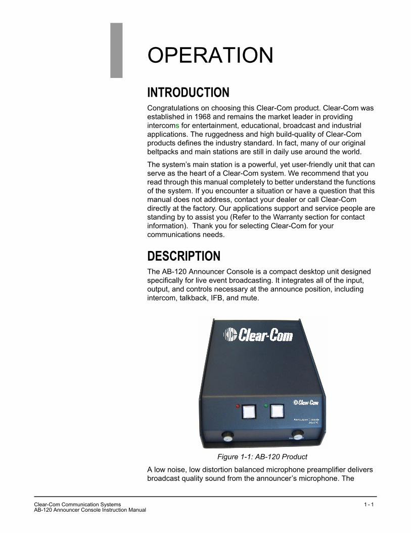
DESCRIPTIONThe AB-120 Announcer Console is a compact desktop unit designed specifically for live event broadcasting. It integrates all of the input, output, and controls necessary at the announce position, including intercom, talkback, IFB, and mute.
Figure 1-1: AB-120 Product
A low noise, low distortion balanced microphone preamplifier delivers broadcast quality sound from the announcer’s microphone. The
1
CA
lear-Com Communication SystemsB-120 Announcer Console Instruction Manual
1 - 1

AB-120 can be used with virtually any broadcast headset or separate microphone or headphone fitted with a Switchcraft™ or Switchcraft style XLR-5M or XLR-6M connector. Microphone gain is jumper selectable to accommodate all microphone types. The microphone output stage uses a high grade transformer for driving the line. Output levels from 0 dB to -50 dB are jumper selectable.
A high output stereo headphone amplifier provides talent with both program audio and cues from the control room, even in the most noisy environments. The console can be configured so that intercom audio and IFB inputs can be heard in the left/right ear or both, helping the talent to instantly identify the source, The unit accepts one or two channels of IFB, which can be standard self powered, three pin circuits like those found on most broadcast IFM systems.
OPERATIONInstant access to an intercom system is available with a talkback button. If the talkback button is pressed, the microphone is momentarily switched from on air to intercom use. The Announcer Console can be connected to virtually any party-line intercom system. The AB-120 connects directly to a Clear-Com party-line system.
A mute button provides momentary silencing of the microphone. Alternately, it can be set to latch when pressed, allowing the talent to switch the microphone on and off with a single switch. The switch is mechanically and electrically mute to ensure no clicking or switching noise is heard when pressed.
The AB-120 plugs into and draws power directly from most intercom and IFB systems, permitting an announce position to be located virtually anywhere, regardless of AC power. When a powered intercom or IFB is not available, the console can be externally powered with the supplied DC adapter.
Clear-Com Communication SystemsAB-120 Announcer Console Instruction Manual
1 - 2

FRONT PANEL
Figure 1-2: AB-120 Front Panel Controls
Selecting Microphone Amplifier GainThe microphone preamplifier and the output line drive amplifier have selectable gains allowing the user to tailor the gain structure to the type of microphone being used and the desired output level. As shipped from the factory, microphone gain is set for a dynamic mic and the output level is set for -10 dBu.
Microphone Preamplifier GainThe microphone preamplifier gain must be set to provide proper operation of the limiter circuit used in the talkback system. The preamplifier can be set for gains of 40, 50, and 60 dB. Dynamic microphones have a nominal output level of approximately -60 dBu. Electret mic typically have an output level of -40 dBu. Jumpers JP9 and JP10 allow selecting the preamplifier gain to 40, 50, and 60 dB.
Jumpers JP9 and JP10 are normally factory set for -60 dB (dynamic microphone).
INPUT LEVEL JP 9 JP 10-60 dB (dynamic microphone) 1-2 1-2-50 dB 2-3 1-2-40 dB (Electret microphone) 2-3 2-3
InterruptInterrupt Non-InterruptNon-Interrupt
AB-120Announcer Console
InterruptLevel
Control
Non-InterruptLevel
Control
MuteIndicator
MuteButton
Talk BackIndicator
Talk BackButton
CA
lear-Com Communication SystemsB-120 Announcer Console Instruction Manual
1 - 3

Line Output Level SelectThe operating level at the output is selectable to accommodate the various types of devices that are to be fed. The microphone input of a console would need -60 dBu whereas the line input of a console might need a level of -10 dBu.
Jumper JP8 allows the selection of three gain structures for the output amplifier and the output connector so the rear panel can be plugged into an alternate header on the printed circuit board that has a 30 dB pad inserted in the output. The combination of JP8 and the 30 dB pad allows an output level selection from 0 dBu to -50 dBu in 10 dB steps.
The output gain is normally factory set to -10 dBu.
Options for PowerThe AB-120 can be powered from the intercom line, the IFB line, or from a local external DC supply. To power it from the intercom line of the IFB line, the unit needs a minimum of 25 VDC. The AB-120 draws approximately 100 mA of current with peaks of 120 mA.
The following topics describe how to power the AB-120 from the three different sources.
Power from the IFB LineTo power the unit from the IFB line, set jump jacks on pins 2 and 3 of JP5. JP5 selects where the positive DC power is sourced from.
If for noise reasons, pin 1 of the IFB input connector can not be connected to power ground of the AB-120, the power cannot be derived from the IFB line.
Power from the Intercom LineTo power the unit from the intercom line, set jump jacks on pins 1 and 2 of JP5. JP5 selects where the positive DC power is sourced from.
Power from an External DC SupplyIf power from the intercom line or IFB line is not available then plug in the DC supply supplied with the unit.
0dBu -10dBu -20dBu -30dBu -40dBu -50dBuOutput Connector J2 J2 J2 J3 J3 J3JP8 Position Open 2-3 1-2 Open 2-3 1-2
Clear-Com Communication SystemsAB-120 Announcer Console Instruction Manual
1 - 4

REAR PANEL CONNECTORS AND CONTROLSThe rear panel of the AB-120 has the following connectors and controls.
• Headset connectors
• Microphone Out Connector
• Male/Female Pair of Intercom Connectors
• IFB Input Connector
• 30 VDC Power Connector
• Channel Select Switch
Figure 1-3: AB-120 Rear Connectors
Headset ConnectorThe standard AB-120 is shipped with a headset connector designed for use with any type of announcer headset. Connection is via a Switchcraft™ XLR-6F connector on the unit. The pinout of the headset connector is as follows:
1. Microphone Lo (-)2. Microphone Hi (+)3. Headphone Common4. Left Headphone (+)5. Right Headphone (-)6. Microphone ShieldThe headset should have a separate shielded twisted pair of wires directly to the microphone, otherwise some earphone to microphone crosstalk may be experienced.
Headset Mic Out IFB
Channel SelectPin 2 (RTS)Pin 3 (CC)
+ 30V 0.45A MAX
Intercom/Talkback
CA
lear-Com Communication SystemsB-120 Announcer Console Instruction Manual
1 - 5

The connector is also 5 pin compatible and most standard intercom headsets can be directly plugged into the unit.
OptionsThe construction of the AB-120 lends itself to modification. The 6 pin XLR could be replaced with a 5 pin XLR.
Next to the headset connector is a 1/4 inch hole intended for the user to install a stereo phone jack for a separate set of headphones.
The 8 pin header on the printed circuit board that the headset connects to has circuits available for preening of electret microphones.
Mic Out ConnectorThe Mic Out connector provides a feed of microphone input after amplification. The connector is an XLR-3M and is as follows:
• Pin 1 = ground shield
• Pin 2 = +ve mic output
• Pin 3 = -ve mic output
Intercom Line Connectors (XLR 3 male and female)The AB-120 has a male and female pair of XLR 3 connectors for the intercom line. The male/female pair of connectors are wired paralleled and intended for loop through connection.
The pinout of the connectors when used with a Clear-Com party-line system is as follows (place the channel select switch to 2):
• Pin 1 - ground shield
• Pin 2 = power (+25 to +30 VDC)
• Pin 3 = audio
The pinout of the connectors when used with TW(RTS) intercom systems is as follows (place the channel select to the desired channel):
• Pin 1 - ground shield
• Pin 2 = audio 1 and power (+25 to +30 VDC)
• Pin 3 = audio 2
IFB (XLR 3 female)The AB-120 has female XLR-3 connectors for the IFB input and is as follows:
• Pin 1 - ground shield
• Pin 2 = IFB 1 and power (+25 to +30 VDC)
• Pin 3 = IFB 2
Clear-Com Communication SystemsAB-120 Announcer Console Instruction Manual
1 - 6
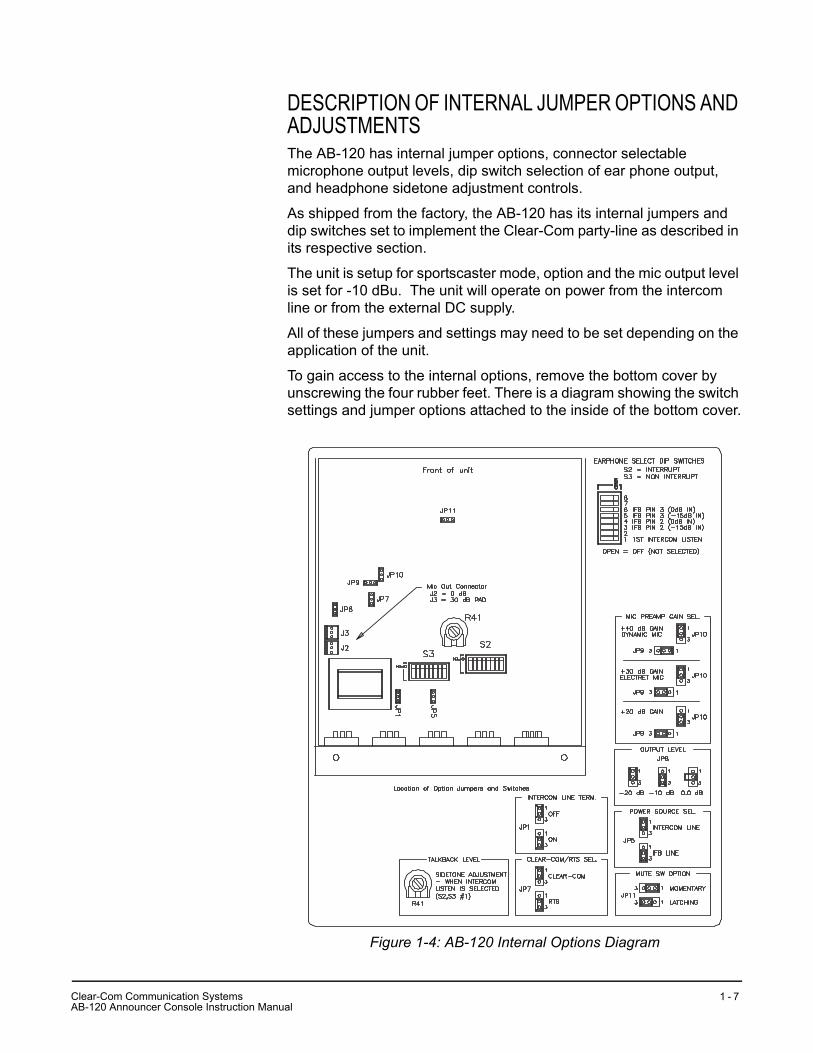
DESCRIPTION OF INTERNAL JUMPER OPTIONS AND ADJUSTMENTSThe AB-120 has internal jumper options, connector selectable microphone output levels, dip switch selection of ear phone output, and headphone sidetone adjustment controls.
As shipped from the factory, the AB-120 has its internal jumpers and dip switches set to implement the Clear-Com party-line as described in its respective section.
The unit is setup for sportscaster mode, option and the mic output level is set for -10 dBu. The unit will operate on power from the intercom line or from the external DC supply.
All of these jumpers and settings may need to be set depending on the application of the unit.
To gain access to the internal options, remove the bottom cover by unscrewing the four rubber feet. There is a diagram showing the switch settings and jumper options attached to the inside of the bottom cover.
Figure 1-4: AB-120 Internal Options Diagram
CA
lear-Com Communication SystemsB-120 Announcer Console Instruction Manual
1 - 7
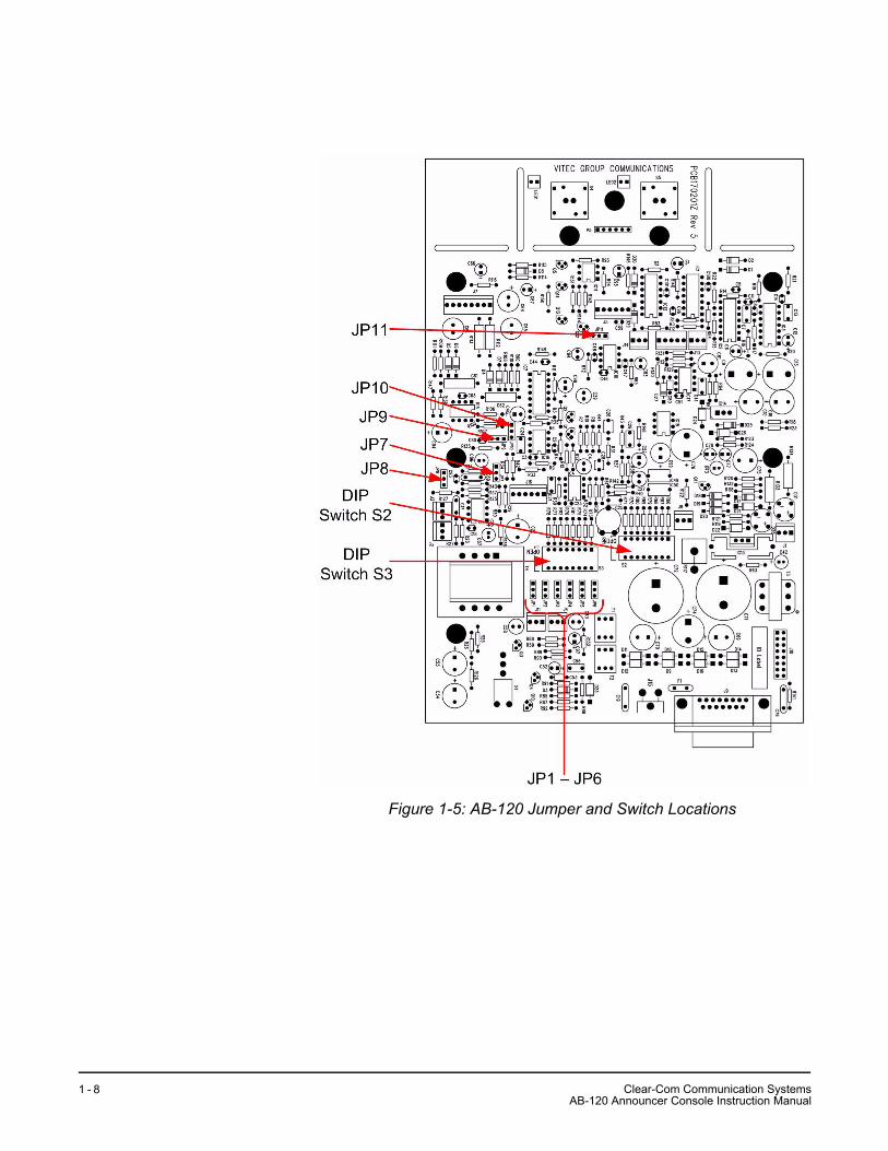
Figure 1-5: AB-120 Jumper and Switch Locations
Clear-Com Communication SystemsAB-120 Announcer Console Instruction Manual
1 - 8

Jumper OptionsThere are eleven two position jumpers that provide many options for the operation of the AB-120. To access these jumpers, remove the bottom cover of the unit. Inside the bottom cover is a label describing the functions of jumper and switch.
Note: Jumpers 2, 3, 4 and 6 are not used.
JP1JP1 provides termination for the intercom line if needed. The AB-120 is always a remote intercom station and therefore does not provide termination for an intercom line. The termination is provided for the cases where the party-line output of the AB-120 is not used and the party-line drive circuit needs termination to be stable and not oscillate.
As shipped from the factory, the jumper is between pins 1 and 2 of JP1 making the termination inactive. To activate termination, place the jumper between pins 2 and 3.
JP7JP7 allows the send gain on the talkback channel to be increased when driving a TW type intercom line, such as RTS. Placing the jumper between pins 2 and 3 increases the send gain approximately 4 dB. JP7 is shipped from the factory with its jumper between pins 1 and 2, providing Clear-Com standard levels to the intercom line.
JP8JP8 provides the selection of desired output level for the microphone output.
JP9 and JP10These JPs provide selection of the desired output level for the microphone output.
JP11JP11 selects the sportscaster or announcer modes of operation for the front panel push button switches. Connection between pins 1 and 2 enables the sportscaster mode and connection between 2 and 3 enables announcer mode.
Microphone Output PadThe microphone output connector on the rear panel can be internally plugged into two different headers on the main PCB. Connecting the output to J2 provides a high level of output. Connecting the output to J3 adds a 30 dB pad in the series to provide a lower level output.
CA
lear-Com Communication SystemsB-120 Announcer Console Instruction Manual
1 - 9
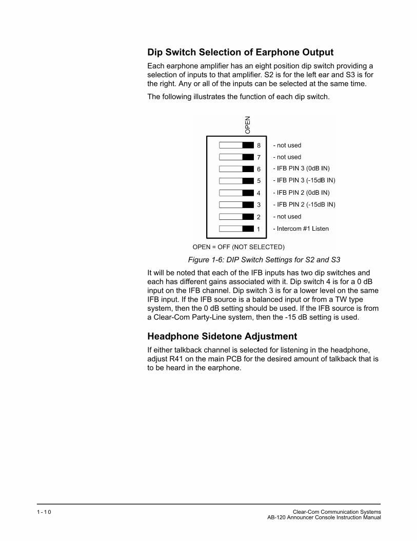
Dip Switch Selection of Earphone OutputEach earphone amplifier has an eight position dip switch providing a selection of inputs to that amplifier. S2 is for the left ear and S3 is for the right. Any or all of the inputs can be selected at the same time.
The following illustrates the function of each dip switch.
Figure 1-6: DIP Switch Settings for S2 and S3
It will be noted that each of the IFB inputs has two dip switches and each has different gains associated with it. Dip switch 4 is for a 0 dB input on the IFB channel. Dip switch 3 is for a lower level on the same IFB input. If the IFB source is a balanced input or from a TW type system, then the 0 dB setting should be used. If the IFB source is from a Clear-Com Party-Line system, then the -15 dB setting is used.
Headphone Sidetone AdjustmentIf either talkback channel is selected for listening in the headphone, adjust R41 on the main PCB for the desired amount of talkback that is to be heard in the earphone.
Clear-Com Communication SystemsAB-120 Announcer Console Instruction Manual
1 - 1 0

APPLICATION OF VARIOUS INTERCOM SYSTEM TYPESThe AB-120 is intended to work with virtually any intercom system. Options, jumpers, and connectors have been provided for the following systems.
• Clear-Com party-line
• TW party-line Systems (RTS)
• Other four wire systems
Clear-Com Party-LineAn all Clear-Com party-line system is described as follows:
IFBIFB is provided by a PIC-4000 two channel IFB system containing interrupt and non-interrupt functionalities.
INTERCOMTalkback is provided from one channel of a Clear-Com party-line system. This single channel is the producer channel. Any announcer pressing the talkback button would speak into this channel. Any or all of the announcers may talk at any time as they are summed on the party-line channel.
PowerPower for the AB-120 is derived from the intercom line, an external DC supply or optionally from the IFB line.
Figure 1-7: AB-120 Connected to a Clear-Com Party-Line System
CA
lear-Com Communication SystemsB-120 Announcer Console Instruction Manual
1 - 1 1

Setting Jumpers
Setting Dip Switches
Wiring of ConnectorsThe pinout for the intercom XLR-3 connector is as follows:
• Pin 1 = ground
• Pin 2 = +30 volts power
• Pin 3 = intercom audio
The pinout for the IFB XLR-3F connector is as follows:
• Pin 1 = ground
• Pin 2 = IFB 2 and power
• Pin 3 = IFB 1
JP1 1-2 Unterminate intercom lineJP2 Not usedJP3 Not usedJP4 Not usedJP-5 1-2 Power intercom lineJP6 Not usedJP-7 1-2 Clear-Com Intercom Level JP-8 Mic output Set per chart in a following sectionJP-9 Mic Pre’p gain Set per chart in a following sectionJP-10 Mic Pre’p gain Set per chart in a following sectionJP-11 Mode Set per chart in a following section
S2 Left ear select S3 Right ear select1 open 1 open2 open 2 open3 close 3 open4 open 4 open 5 open 5 close6 open 6 open7 open 7 open8 open 8 open
Clear-Com Communication SystemsAB-120 Announcer Console Instruction Manual
1 - 1 2

Figure 1-8: AB-120 Connected to a TW Party-Line System
TW Party-Line Systems (RTS)A TW party-line system is described as follows:
IFBIFB is provided by a two channel interrupt and non-interrupt system.
INTERCOMTalkback is provided from one or two channels of a TW party-line system Channel ‘1’ is the producer channel. Any announcer pressing the talkback button would speak into this channel. Any or all of the announcers may talk at any time as they are summed on the party-line channel.
Set the channel switch on the rear panel to ‘1’. If the second power option is installed, any announcer pressing the mute button can talk on that channel.
POWERPower for the AB-120 is derived from the intercom line, an external DC supply or optionally from the IFB.
CA
lear-Com Communication SystemsB-120 Announcer Console Instruction Manual
1 - 1 3

Channel Select Switch = ‘1’
Setting Jumpers
Setting Dip Switches
Wiring of ConnectorsThe pinout for the intercom XLR-3 connector is as follows:
• Pin 1 = ground
• Pin 2 = intercom audio 1 and +30 volts power
• Pin 3 = intercom audio 2
The pinout for the IFB XLR-3F connector is as follows:
• Pin 1 = ground
• Pin 2 = audio 1
• Pin 3 = audio 2
JP1 1-2 Unterminate intercom lineJP-5 1-2 Power intercom lineJP-7 2-3 RTS Intercom Level and JP1 on the option
board if usedJP-8 Mic output Set per chart in a following sectionJP-9 Mic Pre’p
gainSet per chart in a following section
JP-10 Mic Pre’p gain
Set per chart in a following section
JP-11 Mute Set per chart in a following section
S2 Left Ear Select S3 Right Ear Select1 open 1 open2 open 2 open3 close 3 open4 open 4 open 5 open 5 close6 open 6 open7 open 7 open8 open 8 open
Clear-Com Communication SystemsAB-120 Announcer Console Instruction Manual
1 - 1 4
INSTALLATIONThe AB-120 is a versatile interconnection box and can accommodate many types of installation. The AB-120 has two modes of operation; sportscaster mode and announcer mode.
When shipped from the factory the AB-120 has its internal jumpers and dip switches set to implement the Clear-Com party-line setup. The unit will be configured for Sportscaster Console operation and the microphone output level is set for -10 dBu with a dynamic microphone input.
The AB-120 can operate on power from the intercom line or from a suitable external DC power supply.
SPORTSCASTER MODEMOMENTARY MICROPHONE MUTEPlace a jump jack on pins 1 and 2 of JP11. Both front panel buttons are momentary in operation and microphone output is active except when either of the buttons is pressed. The red LED next to the mute button is light where the output is active.
Pressing the mute button turns the output of the microphone circuit off as long as the button is pressed.
Pressing talkback turns the output of the microphone circuit off and sends the signal to the intercom line. The green LED next to this button is lit when the talkback circuit is activated.
ANNOUNCER MODELATCHING MICROPHONEPlace a jump jack on pins 2 and 3 of JP11. In this mode, the microphone on/off button is latching in action and talkback is momentary in action. The red LED next to the on/off button is lit whenever the microphone output is active.
Pressing the on/off button toggles the state of the mic from on to off, or vice versa, each time the button is pressed.
2
CA
lear-Com Communication SystemsB-120 Announcer Console Instruction Manual
2 - 1

AB-120 SYSTEM BLOCK DIAGRAM
Figure 2-9: AB-120 Console Block Diagram
BA
L/U
NB
AL
SE
LEC
T
1/2
6-P
INH
EA
DS
ET
CO
NN
EC
TO
RE
LEC
TR
ET
PO
WE
R
PR
EA
MP
GA
INS
ELE
CT
LIM
ITE
R
LOG
IC
MU
TE
INT
ER
CO
M 1
MU
TE
TA
LLY
CO
UG
H B
UT
TO
N
TA
LKB
AC
K T
ALL
Y
TA
LKB
AC
K
LIN
E L
EV
EL
GA
IN S
ELE
CT
CC
/RT
SG
AIN
SID
ET
ON
EA
DJU
ST
A/B
CH
AN
NE
LS
ELE
CT
(RE
AR
PA
NE
L)
OP
TIO
NA
L30
DB
PA
DLI
NE
LE
VE
L O
UT
INT
ER
CO
MC
LEA
R-C
OM
/RT
SLO
OP
S T
HR
U
PO
WE
RS
TR
IPP
ER
30 V
OLT
PO
WE
RS
UP
PLY
CO
NS
OLE
PO
WE
R
1/2
6-P
INH
EA
DS
ET
CO
NN
EC
TO
R
HE
AD
PH
ON
EO
UT
PU
T
HE
AD
SE
TA
MP
SLE
FT
VO
LUM
E
RIG
HT
VO
LUM
E
LEF
T E
AR
RIG
HT
EA
R
DIP
SW
ITC
HS
ELE
CT
-IN
TE
RC
OM
A-S
PA
RE
-IF
B 2
-IF
B-S
PA
RE
-SP
AR
E
-IN
TE
RC
OM
A-S
PA
RE
-IF
B 2
-IF
B-S
PA
RE
-SP
AR
E
100-
240
VA
C
30 V
DC
IFB
INP
UT
Clear-Com Communication SystemsAB-120 Announcer Console Instruction Manual
2 - 2
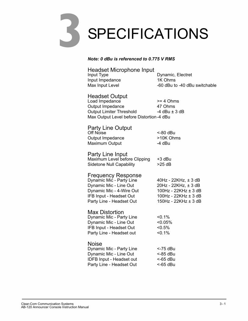
SPECIFICATIONSNote: 0 dBu is referenced to 0.775 V RMS
Headset Microphone InputInput Type Dynamic, ElectretInput Impedance 1K OhmsMax Input Level -60 dBu to -40 dBu switchable
Headset OutputLoad Impedance >= 4 OhmsOutput Impedance 47 OhmsOutput Limiter Threshold -4 dBu ± 3 dBMax Output Level before Distortion-4 dBu
Party Line OutputOff Noise <-80 dBuOutput Impedance >10K OhmsMaximum Output -4 dBu
Party Line InputMaximum Level before Clipping +3 dBuSidetone Null Capability >25 dB
Frequency ResponseDynamic Mic - Party Line 40Hz - 22KHz, ± 3 dBDynamic Mic - Line Out 20Hz - 22KHz, ± 3 dBDynamic Mic - 4-Wire Out 100Hz - 22KHz ± 3 dBIFB Input - Headset Out 100Hz - 22KHz ± 3 dBParty Line - Headset Out 150Hz - 22KHz ± 3 dB
Max DistortionDynamic Mic - Party Line <0.1%Dynamic Mic - Line Out <0.05%IFB Input - Headset Out <0.5%Party Line - Headset out <0.1%
NoiseDynamic Mic - Party Line <-75 dBuDynamic Mic - Line Out <-85 dBuIDFB Input - Headset out <-65 dBuParty Line - Headset Out <-65 dBu
3
CA
lear-Com Communication SystemsB-120 Announcer Console Instruction Manual
3 - 1

Max GainDynamic Mic - Party Line 41 dB ± 3 dBDynamic Mic - Hot Mic Out 40 dB ± 3 dBIFB Input - Headset Out 40 dB/22 dB (switchable) ± 3 dBParty Line - Headset Out 34 dB ± 3 dB
Rear Panel ConnectorsHeadset XLR-6FMicrophone Out XLR-3MIntercom 2 XLR-3 (Male and Female Loop
through)IFB XLR-3FPower 2.1mm jack
Front Panel Controls and Indicators(1) Mute button(1) Mute indicator LED (red)(1) Talk back button(1) Talk back indicator LED (green)(1) Interrupt level control(1) Non-interrupt level control
POWER REQUIREMENTSIntercom/IFB Voltage 25-30 VDCCurrent 100mA idle, 120mA maxDC Adapter 100 - 240VVoltage 30V @ 0.5A
PHYSICAL SPECSDimensions 6”W x 3”H x 8”D
(152mm x 76mm x 203mm)Weight 2 lbs or 0.9 kgOperating Temp Range 32 - 122°F (0 - 50°C)
Notice About SpecificationsWhile Clear-Com makes every attempt to maintain the accuracy of the information contained in its product manuals, that information is subject to change without notice. Performance specifications included in this manual are design-center specifications and are included for customer guidance and to facilitate system installation. Actual operating performance may vary.
Clear-Com Communication SystemsAB-120 Announcer Console Instruction Manual
3 - 2

GLOSSARYSome of the terms used when discussing critical communications for television or theatre may be new to you as they are unique to intercom applications. Although many of the terms are common to other audio applications, to be certain you understand their meanings we offer the following definitions:
All Call: Ability to push one button from the main station and talk to all channels at once on a multiple channel system.
Ambient Noise: Those background sounds that are not part of the specific communication but are picked up by the microphone. Selection of a good “noise-cancelling” mic will reduce ambient noise.
Beltpack: A portable electronics package worn on the belt or mounted on a wall or other convenient location. Interconnects to system with mic cable and is powered by a central power supply or main station.
Bridging, High Impedance (hi-Z): A method of connecting to an audio line (such as Clear-Com) without loading or taking appreciable power from that line. Simply stated, as you add more and more stations to the line, the volume remains constant.
Call Signaling: This feature is included with the majority of Clear-Com products. It is a visual indicator on a station (red light) used to attract the attention of an operator who has removed the headset.
Channel vs. Station: A channel is the line that connects parties together within a party line - it is a two-way talk path. For example, if you have six people who need to hear one director, you have a seven-station single-channel need. If the same director needs to speak privately to any one of the six, add a second channel. You now have a seven-station, two-channel system.
Closed-Circuit: Any intercom which is connected via cable (also called hard-wired). The other type of intercom is wireless and is also available from Clear-Com. However, if you want privacy and versatility, you probably want a closed-circuit system or a combination of both.
Crosstalk: Leakage of audio transmissions from one channel to another.
Dry Pair: A telephone term is used to describe a pair of wires (two conductors) that carry audio but no voltage. Contrast this with a wet pair that carries both audio and voltage.
Duplex: Duplex refers to bi-directional communications. Normal communication between individuals talking face to face is “full duplex”; in other words, you can talk and listen simultaneously. The other alternative is “half-duplex,” such as a push-to-talk situation where one
4
Clear-Com Communication SystemsAB-120 Announcer Console Instruction Manual
4 - 1
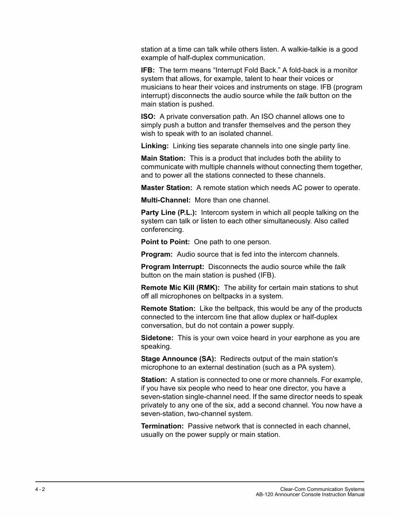
station at a time can talk while others listen. A walkie-talkie is a good example of half-duplex communication.
IFB: The term means “Interrupt Fold Back.” A fold-back is a monitor system that allows, for example, talent to hear their voices or musicians to hear their voices and instruments on stage. IFB (program interrupt) disconnects the audio source while the talk button on the main station is pushed.
ISO: A private conversation path. An ISO channel allows one to simply push a button and transfer themselves and the person they wish to speak with to an isolated channel.
Linking: Linking ties separate channels into one single party line.
Main Station: This is a product that includes both the ability to communicate with multiple channels without connecting them together, and to power all the stations connected to these channels.
Master Station: A remote station which needs AC power to operate.
Multi-Channel: More than one channel.
Party Line (P.L.): Intercom system in which all people talking on the system can talk or listen to each other simultaneously. Also called conferencing.
Point to Point: One path to one person.
Program: Audio source that is fed into the intercom channels.
Program Interrupt: Disconnects the audio source while the talk button on the main station is pushed (IFB).
Remote Mic Kill (RMK): The ability for certain main stations to shut off all microphones on beltpacks in a system.
Remote Station: Like the beltpack, this would be any of the products connected to the intercom line that allow duplex or half-duplex conversation, but do not contain a power supply.
Sidetone: This is your own voice heard in your earphone as you are speaking.
Stage Announce (SA): Redirects output of the main station's microphone to an external destination (such as a PA system).
Station: A station is connected to one or more channels. For example, if you have six people who need to hear one director, you have a seven-station single-channel need. If the same director needs to speak privately to any one of the six, add a second channel. You now have a seven-station, two-channel system.
Termination: Passive network that is connected in each channel, usually on the power supply or main station.
Clear-Com Communication SystemsAB-120 Announcer Console Instruction Manual
4 - 2
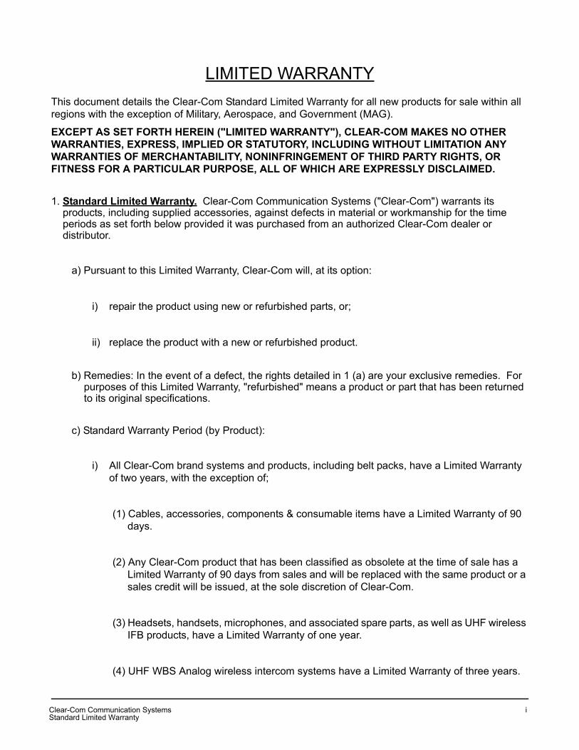
LIMITED WARRANTYThis document details the Clear-Com Standard Limited Warranty for all new products for sale within all regions with the exception of Military, Aerospace, and Government (MAG).
EXCEPT AS SET FORTH HEREIN ("LIMITED WARRANTY"), CLEAR-COM MAKES NO OTHER WARRANTIES, EXPRESS, IMPLIED OR STATUTORY, INCLUDING WITHOUT LIMITATION ANY WARRANTIES OF MERCHANTABILITY, NONINFRINGEMENT OF THIRD PARTY RIGHTS, OR FITNESS FOR A PARTICULAR PURPOSE, ALL OF WHICH ARE EXPRESSLY DISCLAIMED.
1. Standard Limited Warranty. Clear-Com Communication Systems ("Clear-Com") warrants its products, including supplied accessories, against defects in material or workmanship for the time periods as set forth below provided it was purchased from an authorized Clear-Com dealer or distributor.
a) Pursuant to this Limited Warranty, Clear-Com will, at its option:
i) repair the product using new or refurbished parts, or;
ii) replace the product with a new or refurbished product.
b) Remedies: In the event of a defect, the rights detailed in 1 (a) are your exclusive remedies. For purposes of this Limited Warranty, "refurbished" means a product or part that has been returned to its original specifications.
c) Standard Warranty Period (by Product):
i) All Clear-Com brand systems and products, including belt packs, have a Limited Warranty of two years, with the exception of;
(1) Cables, accessories, components & consumable items have a Limited Warranty of 90 days.
(2) Any Clear-Com product that has been classified as obsolete at the time of sale has a Limited Warranty of 90 days from sales and will be replaced with the same product or a sales credit will be issued, at the sole discretion of Clear-Com.
(3) Headsets, handsets, microphones, and associated spare parts, as well as UHF wireless IFB products, have a Limited Warranty of one year.
(4) UHF WBS Analog wireless intercom systems have a Limited Warranty of three years.
Clear-Com Communication SystemsStandard Limited Warranty
i

(5) All software products, including Concert (Client and Server), ECS, Production Maestro and Logic Maestro are warranted for one year and shall substantially conform to published specifications. The media on which the Software is furnished is warranted to be free of defects in material and workmanship (under normal use) for a period of one year.
(6) Any Clear-Com products that are listed within the last time buy period have the same Limited Warranty for their type 1.i 1 - 1.i.5 as above.
d) Any Clear-Com product that is repaired or supplied as a replacement under the terms of this Limited Warranty shall inherit the remaining warranty period from the original product.
e) Standard Warranty Period Start Date
i) Dealer / Distributor Sales: In view of Dealer or Distributor stocking practices, the Standard Warranty Period for products sold through Dealers or Distributors will commence from the Clear-Com invoice date and will include an automatic extension of three months. Any valid warranty claim within the Standard Warranty Period as determined by the Clear-Com invoice date will be covered without further supporting evidence. All warranty claims after this date must be supported by the Customer's proof of purchase that demonstrates the product is still within the Standard Warranty Period (as detailed in Section 1.c.i above, plus the automatic three month extension) from their purchase date.
ii) Direct Sales: The Standard Warranty Period will commence from the date the product was shipped from Clear-Com to the Customer. The Standard Warranty Period start date for contracts that include commissioning will be the date of the Site Acceptance Test (SAT) or one month from conclusion of the commissioning project, whichever is earlier.
f) Invalidation of Warranty
i) This Limited Warranty shall be invalidated if the product's outer case has been opened and internal modifications have been made or damage has occurred, or upon the occurrence of other damage or failure not attributable to normal wear and tear. Authorized modifications with Clear-Com's express written permission will not invalidate the warranty.
g) Software Updates
i) Software Updates are released periodically to correct discovered program bugs. During the Warranty Period, software updates are available to Customers free of charge.
Clear-Com Communication SystemsStandard Limited Warranty
i i

h) Software Upgrades
i) Software Upgrades include new Features and/or Functional Enhancements and are not included as part of the Standard Warranty but may be purchased at the published rates.
ii) Note: In the absence of a Software Update containing a program correction and no available workaround to mitigate the problem, at the discretion of Service, Sales, Engineering, or Product Management, the Customer may be provided a Software Upgrade under warranty.
2. Exclusions. Services do not cover damage or failure caused by any occurrence beyond Clear-Com's reasonable control, including without limitation acts of God, fire, flooding, earthquake, lightning, failure of electric power or air conditioning, neglect, misuse, improper operation, war, government regulations, supply shortages, riots, sabotage, terrorism, unauthorized modifications or repair, strikes, labor disputes or any product failure that Clear-Com determines is not a result of failure in the Services provided by Clear-Com. Further Services excluded from this Agreement include: services required due to errors or omissions in Customer purchase orders; installation or maintenance of wiring, circuits, electrical conduits or devices external to the products; replacement or reconditioning of products which, in Clear-Com's opinion cannot be reliably maintained or properly serviced due to excessive wear or deterioration; Customer's failure to maintain the installation site in accordance with the environmental specifications of the products; or service on products removed from the location originally specified by Customer and/or reinstalled without the prior written approval of Clear-Com. Customer will pay Clear-Com's then current published charges to restore such Covered Products to a condition eligible for further service under this Agreement. Clear-Com shall be excused from and shall not be liable for any failure or delay in performance under this Agreement due to the foregoing or any causes beyond its reasonable control.
3. Limitation of Liability. IN NO EVENT WILL CLEAR-COM BE LIABLE UNDER THIS AGREEMENT FOR ANY INDIRECT, SPECIAL, INCIDENTAL OR CONSEQUENTIAL DAMAGES (INCLUDING WITHOUT LIMITATION LOST PROFITS), REGARDLESS OF THE FORM OF ACTION, EVEN IF ADVISED IN ADVANCE OF THE POSSIBILITY OF SUCH DAMAGES.
4. Assignment. Neither party may assign this Agreement or any portion thereof without the prior written consent of the other, except in the event of a merger, sale of all or substantially all of the assets or other corporate reorganization.
5. Ownership of replaced parts or product. All replaced parts or products become the property of Clear-Com.
6. Entire Agreement. This Agreement constitutes the entire agreement between the parties with respect to the subject matter hereof, and supersedes all prior or contemporaneous proposals, oral or written, and all other communications between them relating to the subject matter of this Agreement.
Clear-Com Communication SystemsStandard Limited Warranty
i i i

Clear-Com Communication SystemsStandard Limited Warranty
i v

TECHNICAL SUPPORT & REPAIR POLICY
NOVEMBER 1, 2008In order to ensure that your experience with Clear-Com and our World Class products is as beneficial, effective and efficient as possible, we would like to define the policies and share some "best practices" that can accelerate any problem solving processes which we may find necessary and to enhance your customer service experience. Our Technical Support, Return Material Authorization, and Repair Policies are set forth below. These Policies are subject to revision and constantly evolve in order to address our Customers' and the Market's needs. Accordingly these are provided by way of guidance and for information only and may be changed at anytime with or without Notice.
TECHNICAL SUPPORT POLICY
a) Telephone, online, and e-mail technical support will be provided by the Customer Service Center free of charge during the Warranty Period.
b) Technical support will be provided free of charge for all software products under the following conditions:
i) The application, operating, and embedded software is installed on a product covered by Clear-Com's Limited Warranty, and:
(1) The software is at the current release level; or,
(2) The software is one (1) version removed from current.
ii) Older versions of software will receive "best-effort" support, but will not be updated to correct reported bugs or add requested functionality.
c) For Technical Support:
i) North and South America, (inc. Canada, Mexico, and the Caribbean) & US Military:Hours: 0800 - 1700 Pacific TimeDays: Monday - FridayTel: +1 510 337 6600Email: [email protected]
ii) Europe, the Middle East and Africa:Hours: 0800 - midnight Central European Time
Clear-Com Communication SystemsTechnical Support & Repair Policy
v

Days: Monday - FridayTel: +49 40 853 999 700Email: [email protected]
iii) Asia-Pacific:Hours: 0800 - 1700 Pacific TimeDays: Monday - FridayTel: +1 510 337 6600Email: [email protected]
d) Email Technical Support is available for all Clear-Com branded products free of charge for the life of the product, or two years after a product has been classified as obsolete, whichever comes first.
e) Support for Distributor and Dealer Sales
i) Distributors and Dealers may utilize the Customer Service Centers once a system has been installed and commissioned. Clear-Com Systems and Applications Engineers will provide support to the Distributor from the pre-sales stage through to satisfactory installation for new system purchases. Customers will be encouraged to contact their Dealer or Distributor with their installation and technical support enquires rather than using the Customer Service Centers directly.
f) Support for Direct Sales
i) Customers may utilize the Customer Service Centers once a system has been installed and commissioned by Clear-Com Systems and Applications Engineers, or in the case of project installations, once the Project Team has completed the hand-over to the Support Centers.
RETURN MATERIAL AUTHORIZATION POLICY
a) Authorizations: All products returned to Clear-Com or a Clear-Com Authorized Service Partner must be identified by a Return Material Authorization (RMA) number.
b) The Customer will be provided with an RMA number upon contacting Clear-Com Sales Support as instructed below.
c) The RMA number must be obtained from Clear-Com via phone or email prior to returning product
to the Service Center. Product received by the Service Center without a proper RMA number is subject to return to the Customer at the Customer's expense.
Clear-Com Communication SystemsTechnical Support & Repair Policy
v i

d) Damaged equipment will be repaired at the Customer's expense.
e) Returns are subject to a 15% restocking fee.
f) Advance Warranty Replacements (AWRs);
i) During the first 30 days of the Standard Warranty Period: Once the equipment fault has been verified by Clear-Com or its authorized representative, Clear-Com will ship a new replacement product. The Customer will be provided with an RMA number and be required to return the faulty equipment within 14 days of receipt of the replacement or will be invoiced for the list price of a new product.
ii) During days 31-90 of the Standard Warranty Period: Once the equipment fault has been verified by Clear-Com or its authorized representative, Clear-Com will ship a like-new, fully refurbished replacement product. The Customer will be provided with an RMA number and be required to return the faulty equipment within 14 days of receipt of the replacement or will be invoiced for the list price of a new product.
iii) To obtain an RMA number or request an AWR:
(1) North and South America, Asia-Pacific, and US Military:Hours: 0800 - 1700 Pacific TimeDays: Monday - FridayTel: +1 510 337 6600Email: [email protected]
(2) Europe, the Middle East and Africa:Hours: 0800 - 1700 GMT + 1Days: Monday - FridayTel: + 44 1223 815000Email: [email protected]
iv) Note: AWRs are not available for UHF WBS Analog wireless intercom systems. UHF WBS Analog wireless intercom systems out-of-box failures must be returned to Alameda for repair.
v) Note: Out-of-box failures returned after 90 days will be repaired and not replaced unless approved by Clear-Com Management.
vi) Note: AWRs are not available after 90 days of receipt of product unless an AWR Warranty Extension is purchased at the time of product purchase.
Clear-Com Communication SystemsTechnical Support & Repair Policy
v i i

vii) Note: Shipping charges, including duties, taxes, and insurance (optional), to Clear-Com's factory is the responsibility of the Customer. Shipping AWRs from Clear-Com is at Clear-Com's expense (normal ground or international economy delivery). Requests for expedited shipping (E.g. "Next-Day Air") and insurance are the responsibility of the Customer.
REPAIR POLICYa) Repair Authorizations: All products sent to Clear-Com or a Clear-Com Authorized Service Partner
for repair must be identified by a Repair Authorization (RA) number (see above).
b) The Customer will be provided with an RA number upon contacting Clear-Com Customer Services as instructed below.
c) The RA number must be obtained from Clear-Com via phone or email prior to returning product to the Service Center. Product received by the Service Center without a proper RA number is subject to return to the Customer at the Customer's expense.
d) Return for Repair
i) Customers are required to ship equipment at their own cost (including transportation, packing, transit, insurance, taxes and duties) to Clear-Com's designated location for repair.
(1) Clear-Com will pay for the equipment to be returned to the Customer when it is repaired under warranty.
(2) Shipping from Clear-Com is normal ground delivery or international economy. Requests for expedited shipping (E.g. "Next-Day Air") and insurance are the responsibility of the Customer.
ii) Clear-Com does not provide temporary replacement equipment ("loaner") during the period the product is at the factory for repair. Customers should consider a potential prolonged outage during the repair cycle, and if required for continuous operations purchase minimum spare equipment required or purchase an AWR Warranty Extension.
iii) No individual parts or subassemblies will be provided under warranty, and warranty repairs will be completed only by Clear-Com or its Authorized Service Partners.
iv) Customers requesting a non-warranty repair will be provided an estimate of the total repair cost prior to the return of the equipment. In the event that Clear-Com is unable to estimate
Clear-Com Communication SystemsTechnical Support & Repair Policy
v i i i

the cost of repair, the Customer may elect to return the product to the factory for an estimate. The Customer is responsible for shipping costs both to and from the factory in the event they choose not to accept the estimate.
v) The Customer must provide either a purchase order for the repair work, or will be required to make an advance payment (as a debit against the Dealer's line of credit, or credit card) prior to the repaired product being returned to the Customer.
vi) For requesting a Repair Authorization number:
(1) North and South America, Asia-Pacific, and US Military:Hours: 0800 - 1700 Pacific TimeDays: Monday - FridayTel: +1 510 337 6600Email: [email protected]
(2) Europe, the Middle East and Africa:Hours: 0800 - midnight Central European TimeDays: Monday - FridayTel: +49 40 853 999 700Email: [email protected]
vii) Note: Clear-Com's Limited Warranty does not cover normal wear and tear. The Customer will be charged the full cost of the repair if their equipment has been tampered with by non-approved personnel, or has been subject to damage through electrical failure, liquid damage or mishandling. The Customer Service Center will provide the Customer with a cost estimate for any such repairs prior to undertaking the work.
Clear-Com Communication SystemsTechnical Support & Repair Policy
i x
Top Related