


Languages
Pages
Legal

UML Tutorial for C++ - Windows Platform GDPro 5.0
-1-
©2000 Advanced Software Technologies, Inc.
Chapter 8: Sequence Diagram
The Sequence Diagram
What is a Sequence Diagram
This diagram is a model describing how groups of objects collaborate in some behavior over time.
The diagram captures the behavior of a single use case.
It shows objects and the messages that are passed between these objects in the use case.
When to use a sequence diagram
A good design can have lots of small methods in different classes. Because of this it can be difficultto figure out the overall sequence of behavior. This diagram is simple and visually logical, so it iseasy to see the sequence of the flow of control.
A sequence diagram also clearly shows concurrent processes and activations.
Characteristics
Represents an interaction (messages) exchanged among collaborating objects for a specific result
It shows time sequence not easily shown in a collaboration diagram
It does not show relations between objects
It can show general forms that do not deal with objects but with class interaction
Used more for real time types of applications
Creating the Sequence Diagram
You use the Sequence Diagram model to describe the aspects of your new system that change overtime. These are events that mark changes, sequences of events, and so forth. In other words, this modelis used to specify and implement the control aspects of a system. It includes time sequences but does notinclude object relationships. The Sequence Diagram model allows you to graphically display variousinteractions among objects as they send messages to one another over time.
The time sequence interaction is shown on this diagram. It shows the time sequence of the objectsparticipating in the interaction. The two dimensions of a sequence diagram consist of the verticaldimension (time), and the horizontal dimension (different objects).
In this tutorial, you will create the Sequence Diagram using GDPro’s automatic model generation feature.After using this feature some enhancements to the diagram are required but it requires much less effortthan starting from the beginning.
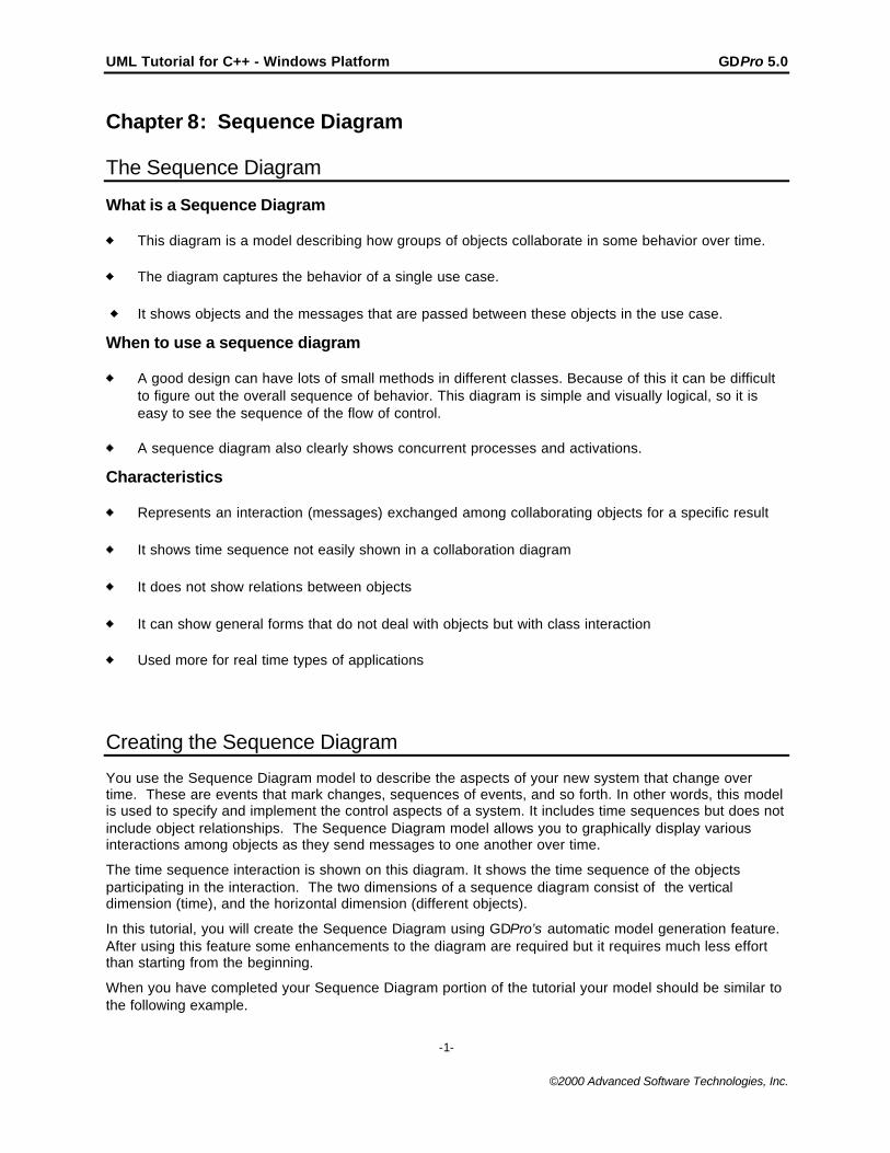
When you have completed your Sequence Diagram portion of the tutorial your model should be similar tothe following example.
UML Tutorial for C++ - Windows Platform GDPro 5.0
-2-
©2000 Advanced Software Technologies, Inc.
Note: The diagram shown is for reference only. Use the instructions beginning on the next page todraw your Sequence diagram.
To Draw the Sequence Diagram Automatically
1. Open the previously created class diagram called CLD_1_Members Institution if it is not presentlythe current diagram.
2. We do not want all the classes in this diagram to appear in the sequence diagram so select only thefollowing classes in the CLD_1_Members Institution diagram:
- User- ATM- Consortium- Branch
Note: You can select multiple classes by holding down the Shift key and clicking on each class youwant included.
3. Right-click anywhere on the background of the design. The Utilities background menu opens.
UML Tutorial for C++ - Windows Platform GDPro 5.0
-3-
©2000 Advanced Software Technologies, Inc.
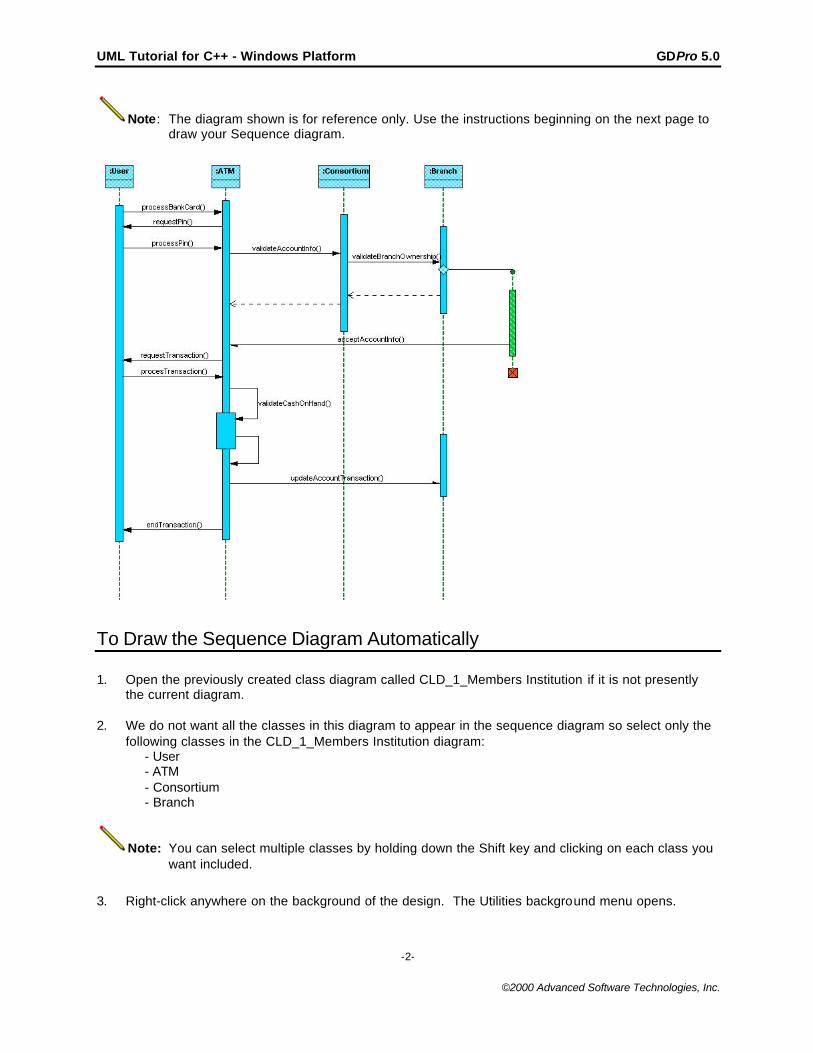
4. Choose CREATE ASSOCIATED DIAGRAM ->AUTOMATIC ->SEQUENCE DIAGRAM. TheDiagram Name dialog box opens. The name of this diagram is automatically generated based onthe name of the diagram. However you can edit this name if you want. A description of the diagramis also automatically created and can be edited.
5. Click the drop-down arrow in the text box located below the Classes label. A drop down menuopens.
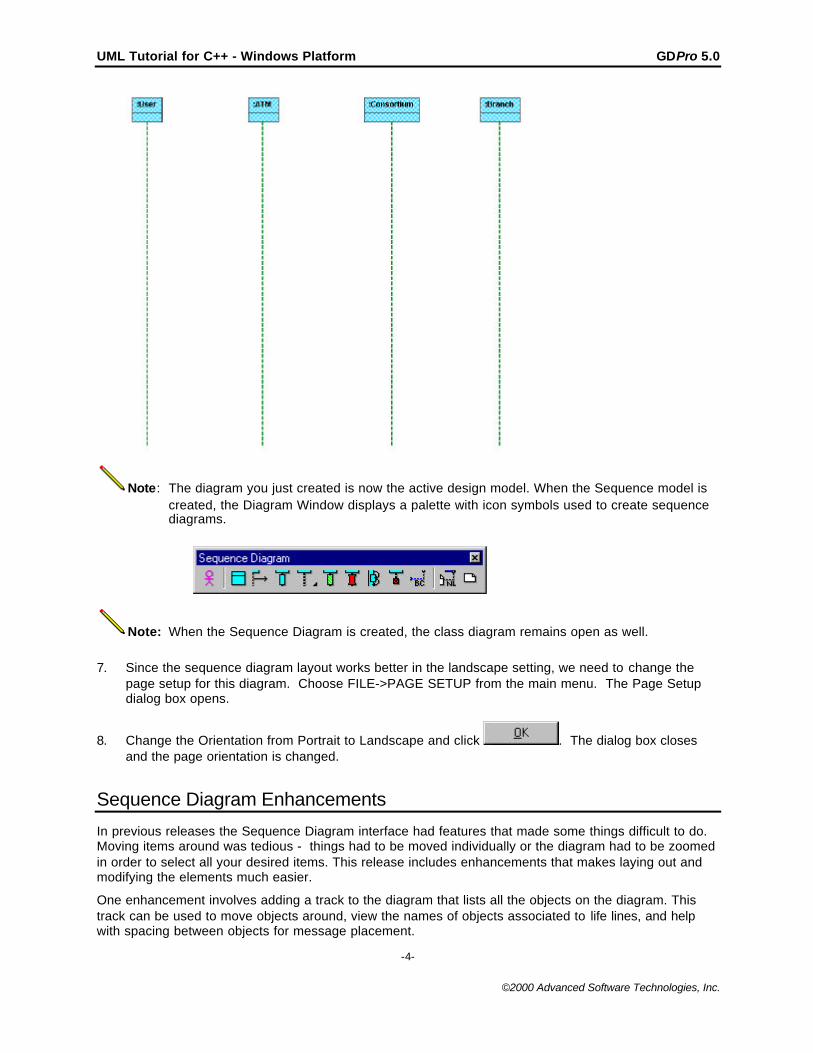
6. Select the option "Selected" and click . After the new diagram is created, the dialogbox closes and a new Diagram Window opens. The new diagram created should resemble thefollowing Sequence Diagram.
UML Tutorial for C++ - Windows Platform GDPro 5.0
-4-
©2000 Advanced Software Technologies, Inc.
Note: The diagram you just created is now the active design model. When the Sequence model iscreated, the Diagram Window displays a palette with icon symbols used to create sequencediagrams.
Note: When the Sequence Diagram is created, the class diagram remains open as well.
7. Since the sequence diagram layout works better in the landscape setting, we need to change thepage setup for this diagram. Choose FILE->PAGE SETUP from the main menu. The Page Setupdialog box opens.
8. Change the Orientation from Portrait to Landscape and click . The dialog box closesand the page orientation is changed.
Sequence Diagram Enhancements
In previous releases the Sequence Diagram interface had features that made some things difficult to do.Moving items around was tedious - things had to be moved individually or the diagram had to be zoomedin order to select all your desired items. This release includes enhancements that makes laying out andmodifying the elements much easier.
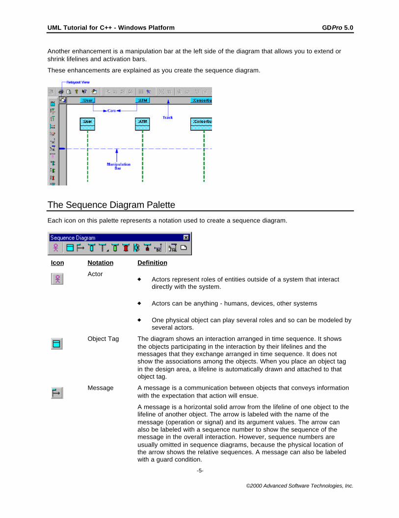
One enhancement involves adding a track to the diagram that lists all the objects on the diagram. Thistrack can be used to move objects around, view the names of objects associated to life lines, and helpwith spacing between objects for message placement.
UML Tutorial for C++ - Windows Platform GDPro 5.0
-5-
©2000 Advanced Software Technologies, Inc.
Another enhancement is a manipulation bar at the left side of the diagram that allows you to extend orshrink lifelines and activation bars.
These enhancements are explained as you create the sequence diagram.
The Sequence Diagram Palette
Each icon on this palette represents a notation used to create a sequence diagram.
Icon Notation Definition
ActorActors represent roles of entities outside of a system that interactdirectly with the system.
Actors can be anything - humans, devices, other systems
One physical object can play several roles and so can be modeled byseveral actors.
Object Tag The diagram shows an interaction arranged in time sequence. It showsthe objects participating in the interaction by their lifelines and themessages that they exchange arranged in time sequence. It does notshow the associations among the objects. When you place an object tagin the design area, a lifeline is automatically drawn and attached to thatobject tag.
Message A message is a communication between objects that conveys informationwith the expectation that action will ensue.
A message is a horizontal solid arrow from the lifeline of one object to thelifeline of another object. The arrow is labeled with the name of themessage (operation or signal) and its argument values. The arrow canalso be labeled with a sequence number to show the sequence of themessage in the overall interaction. However, sequence numbers areusually omitted in sequence diagrams, because the physical location ofthe arrow shows the relative sequences. A message can also be labeledwith a guard condition.
UML Tutorial for C++ - Windows Platform GDPro 5.0
-6-
©2000 Advanced Software Technologies, Inc.
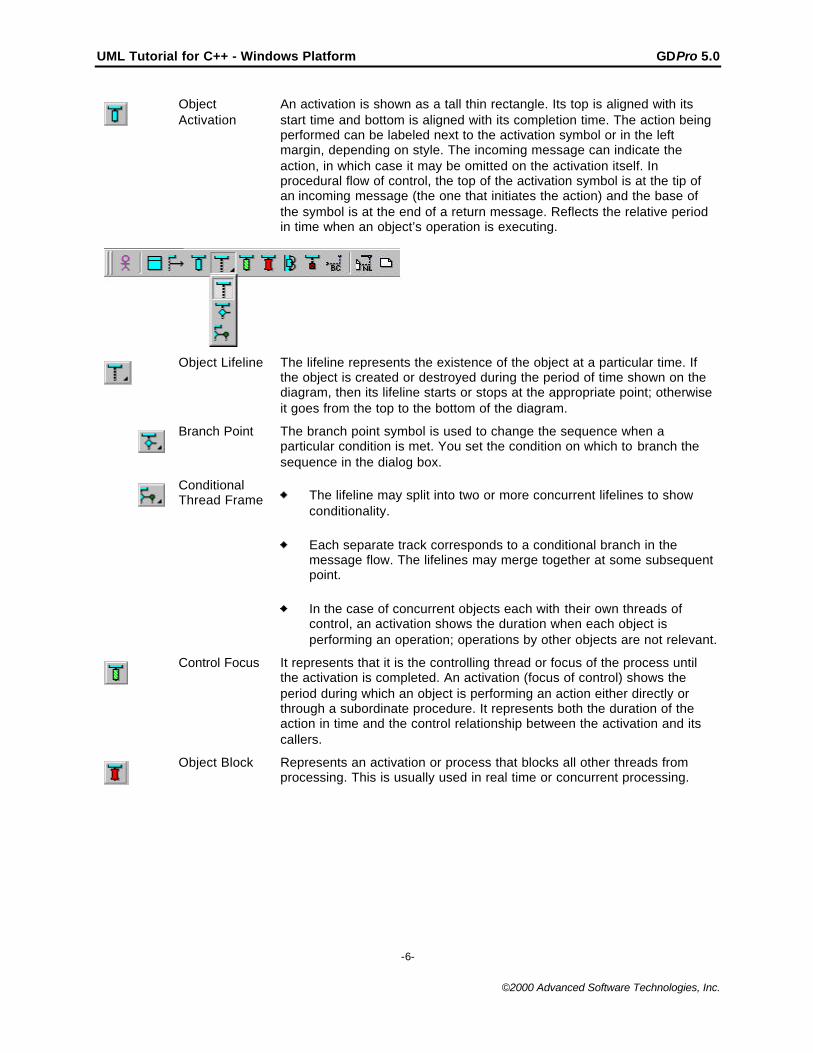
ObjectActivation
An activation is shown as a tall thin rectangle. Its top is aligned with itsstart time and bottom is aligned with its completion time. The action beingperformed can be labeled next to the activation symbol or in the leftmargin, depending on style. The incoming message can indicate theaction, in which case it may be omitted on the activation itself. Inprocedural flow of control, the top of the activation symbol is at the tip ofan incoming message (the one that initiates the action) and the base ofthe symbol is at the end of a return message. Reflects the relative periodin time when an object’s operation is executing.
Object Lifeline The lifeline represents the existence of the object at a particular time. Ifthe object is created or destroyed during the period of time shown on thediagram, then its lifeline starts or stops at the appropriate point; otherwiseit goes from the top to the bottom of the diagram.
Branch Point The branch point symbol is used to change the sequence when aparticular condition is met. You set the condition on which to branch thesequence in the dialog box.
ConditionalThread Frame The lifeline may split into two or more concurrent lifelines to show
conditionality.
Each separate track corresponds to a conditional branch in themessage flow. The lifelines may merge together at some subsequentpoint.
In the case of concurrent objects each with their own threads ofcontrol, an activation shows the duration when each object isperforming an operation; operations by other objects are not relevant.
Control Focus It represents that it is the controlling thread or focus of the process untilthe activation is completed. An activation (focus of control) shows theperiod during which an object is performing an action either directly orthrough a subordinate procedure. It represents both the duration of theaction in time and the control relationship between the activation and itscallers.
Object Block Represents an activation or process that blocks all other threads fromprocessing. This is usually used in real time or concurrent processing.
UML Tutorial for C++ - Windows Platform GDPro 5.0
-7-
©2000 Advanced Software Technologies, Inc.
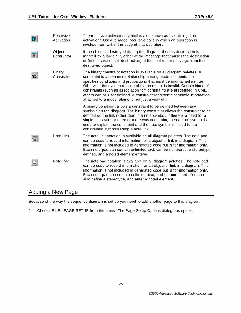
RecursiveActivation
The recursive activation symbol is also known as “self-delegationactivation”. Used to model recursive calls in which an operation isinvoked from within the body of that operation.
ObjectDestructor
If the object is destroyed during the diagram, then its destruction ismarked by a large “X”, either at the message that causes the destructionor (in the case of self-destruction) at the final return message from thedestroyed object.
BinaryConstraint
The binary constraint notation is available on all diagram palettes. Aconstraint is a semantic relationship among model elements thatspecifies conditions and propositions that must be maintained as true.Otherwise the system described by the model is invalid. Certain kinds ofconstraints (such as association "or" constraint) are predefined in UML,others can be user defined. A constraint represents semantic informationattached to a model element, not just a view of it.
A binary constraint allows a constraint to be defined between anysymbols on the diagram. The binary constraint allows the constraint to bedefined on the link rather than in a note symbol. If there is a need for asingle constraint or three or more way constraint, then a note symbol isused to explain the constraint and the note symbol is linked to theconstrained symbols using a note link.
Note Link The note link notation is available on all diagram palettes. The note padcan be used to record information for a object or link in a diagram. Thisinformation is not included in generated code but is for information only.Each note pad can contain unlimited text, can be numbered, a stereotypedefined, and a noted element entered.
Note Pad The note pad notation is available on all diagram palettes. The note padcan be used to record information for an object or link in a diagram. Thisinformation is not included in generated code but is for information only.Each note pad can contain unlimited text, and be numbered. You canalso define a stereotype, and enter a noted element.
Adding a New Page
Because of the way the sequence diagram is set up you need to add another page to this diagram.
1. Choose FILE->PAGE SETUP from the menu. The Page Setup Options dialog box opens.
UML Tutorial for C++ - Windows Platform GDPro 5.0
-8-
©2000 Advanced Software Technologies, Inc.
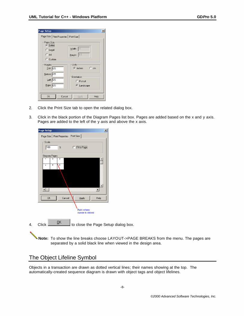
2. Click the Print Size tab to open the related dialog box.
3. Click in the black portion of the Diagram Pages list box. Pages are added based on the x and y axis.Pages are added to the left of the y axis and above the x axis.
4. Click to close the Page Setup dialog box.
Note: To show the line breaks choose LAYOUT->PAGE BREAKS from the menu. The pages areseparated by a solid black line when viewed in the design area.
The Object Lifeline Symbol
Objects in a transaction are drawn as dotted vertical lines; their names showing at the top. Theautomatically-created sequence diagram is drawn with object tags and object lifelines.
UML Tutorial for C++ - Windows Platform GDPro 5.0
-9-
©2000 Advanced Software Technologies, Inc.
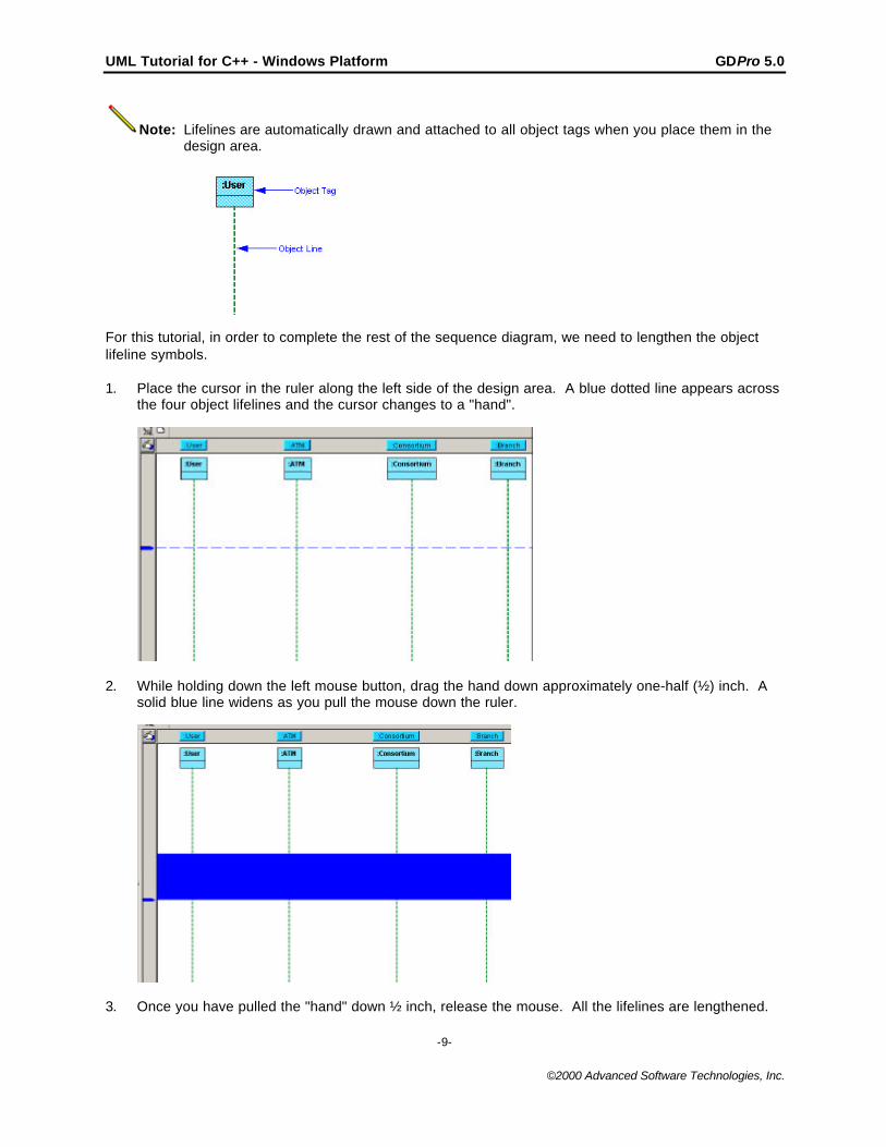
Note: Lifelines are automatically drawn and attached to all object tags when you place them in thedesign area.
For this tutorial, in order to complete the rest of the sequence diagram, we need to lengthen the objectlifeline symbols.
1. Place the cursor in the ruler along the left side of the design area. A blue dotted line appears acrossthe four object lifelines and the cursor changes to a "hand".
2. While holding down the left mouse button, drag the hand down approximately one-half (½) inch. Asolid blue line widens as you pull the mouse down the ruler.
3. Once you have pulled the "hand" down ½ inch, release the mouse. All the lifelines are lengthened.

UML Tutorial for C++ - Windows Platform GDPro 5.0
-10-
©2000 Advanced Software Technologies, Inc.
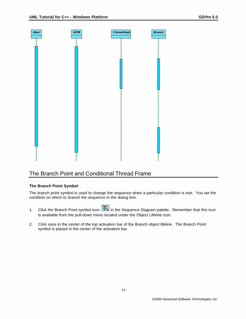
The Object Activation Symbol
Once the lifeline symbols are the correct length we are ready for the next step in creating the sequencediagram. The activation symbol represents a thread that can execute concurrently with other threads. Inthe sequence diagram, the activation symbols are placed on top of the object lifeline symbols.
1. Click the SQD Object Activation icon in the Sequence Diagram palette.
2. Place the cursor near the top of the object lifeline symbol labeled "User" and click once. The ObjectActivation symbol is placed on the lifeline symbol.
3. To stretch the symbol, place the cursor on the bottom edge of the blue box. The cursor changes to
the stretch cursor . Drag the cursor until the activation symbol is just above the end of the lifelinesymbol.
4. Repeat steps 1 through 3 to place activation symbols on the remaining object lifeline symbols. Yourdiagram should resemble the following graphic.
UML Tutorial for C++ - Windows Platform GDPro 5.0
-11-
©2000 Advanced Software Technologies, Inc.
The Branch Point and Conditional Thread Frame
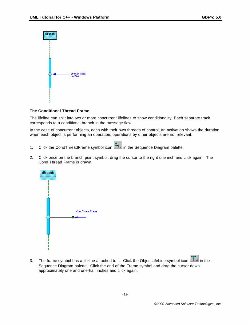
The Branch Point Symbol
The branch point symbol is used to change the sequence when a particular condition is met. You set thecondition on which to branch the sequence in the dialog box.
1. Click the Branch Point symbol icon in the Sequence Diagram palette. Remember that this iconis available from the pull-down menu located under the Object Lifeline icon.
2. Click once in the center of the top activation bar of the Branch object lifeline. The Branch Pointsymbol is placed in the center of the activation bar.
UML Tutorial for C++ - Windows Platform GDPro 5.0
-12-
©2000 Advanced Software Technologies, Inc.
The Conditional Thread Frame
The lifeline can split into two or more concurrent lifelines to show conditionality. Each separate trackcorresponds to a conditional branch in the message flow.
In the case of concurrent objects, each with their own threads of control, an activation shows the durationwhen each object is performing an operation; operations by other objects are not relevant.
1. Click the CondThreadFrame symbol icon in the Sequence Diagram palette.
2. Click once on the branch point symbol, drag the cursor to the right one inch and click again. TheCond Thread Frame is drawn.
3. The frame symbol has a lifeline attached to it. Click the ObjectLifeLine symbol icon in theSequence Diagram palette. Click the end of the Frame symbol and drag the cursor downapproximately one and one-half inches and click again.
UML Tutorial for C++ - Windows Platform GDPro 5.0
-13-
©2000 Advanced Software Technologies, Inc.
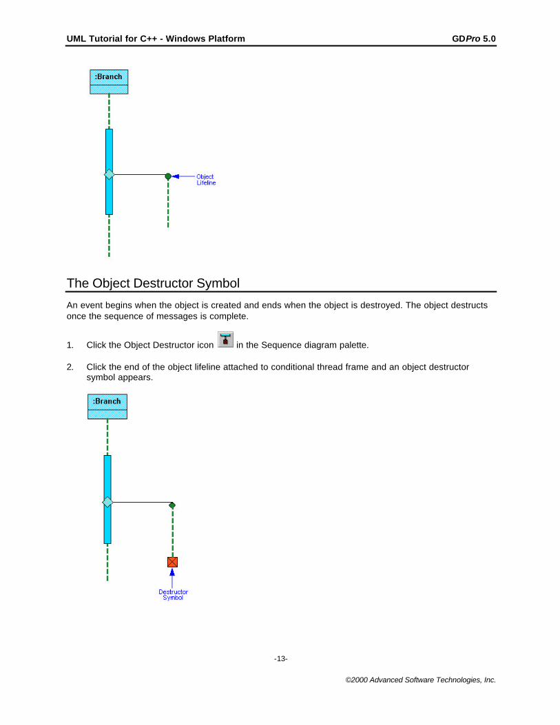
The Object Destructor Symbol
An event begins when the object is created and ends when the object is destroyed. The object destructsonce the sequence of messages is complete.
1. Click the Object Destructor icon in the Sequence diagram palette.
2. Click the end of the object lifeline attached to conditional thread frame and an object destructorsymbol appears.
UML Tutorial for C++ - Windows Platform GDPro 5.0
-14-
©2000 Advanced Software Technologies, Inc.
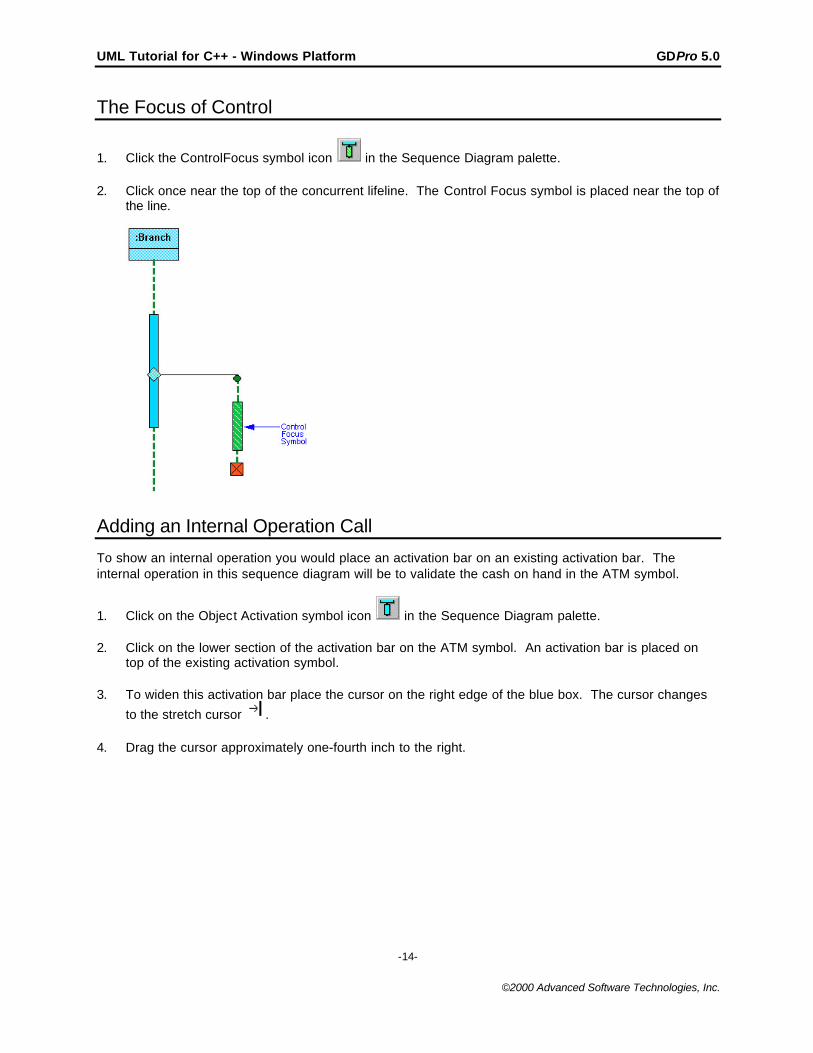
The Focus of Control
1. Click the ControlFocus symbol icon in the Sequence Diagram palette.
2. Click once near the top of the concurrent lifeline. The Control Focus symbol is placed near the top ofthe line.
Adding an Internal Operation Call
To show an internal operation you would place an activation bar on an existing activation bar. Theinternal operation in this sequence diagram will be to validate the cash on hand in the ATM symbol.
1. Click on the Object Activation symbol icon in the Sequence Diagram palette.
2. Click on the lower section of the activation bar on the ATM symbol. An activation bar is placed ontop of the existing activation symbol.
3. To widen this activation bar place the cursor on the right edge of the blue box. The cursor changes
to the stretch cursor .
4. Drag the cursor approximately one-fourth inch to the right.
UML Tutorial for C++ - Windows Platform GDPro 5.0
-15-
©2000 Advanced Software Technologies, Inc.
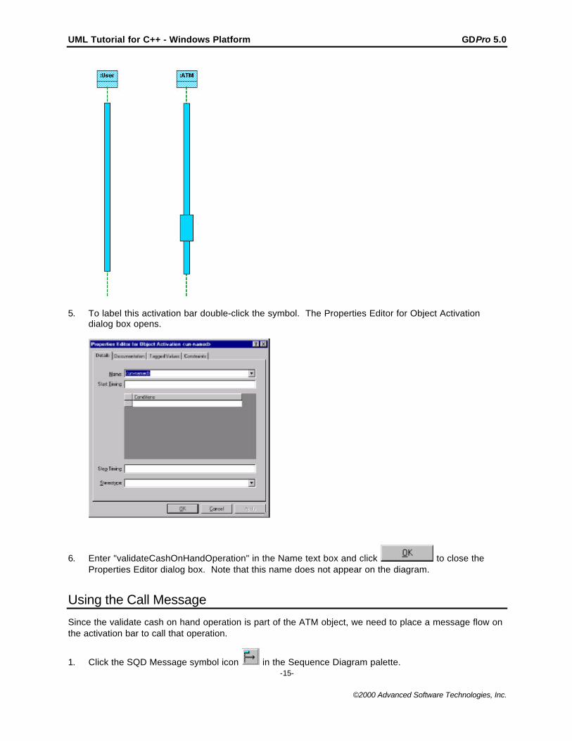
5. To label this activation bar double-click the symbol. The Properties Editor for Object Activationdialog box opens.
6. Enter "validateCashOnHandOperation" in the Name text box and click to close theProperties Editor dialog box. Note that this name does not appear on the diagram.
Using the Call Message
Since the validate cash on hand operation is part of the ATM object, we need to place a message flow onthe activation bar to call that operation.
1. Click the SQD Message symbol icon in the Sequence Diagram palette.
UML Tutorial for C++ - Windows Platform GDPro 5.0
-16-
©2000 Advanced Software Technologies, Inc.
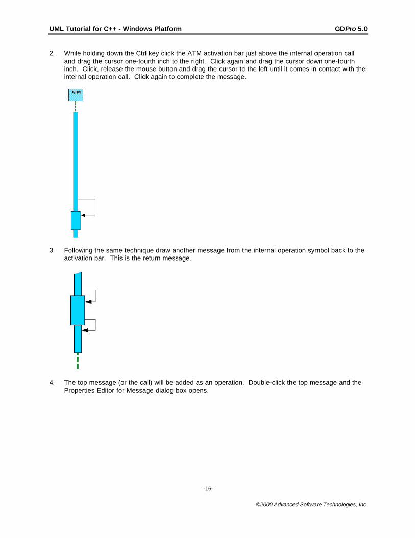
2. While holding down the Ctrl key click the ATM activation bar just above the internal operation calland drag the cursor one-fourth inch to the right. Click again and drag the cursor down one-fourthinch. Click, release the mouse button and drag the cursor to the left until it comes in contact with theinternal operation call. Click again to complete the message.
3. Following the same technique draw another message from the internal operation symbol back to theactivation bar. This is the return message.
4. The top message (or the call) will be added as an operation. Double-click the top message and theProperties Editor for Message dialog box opens.
UML Tutorial for C++ - Windows Platform GDPro 5.0
-17-
©2000 Advanced Software Technologies, Inc.
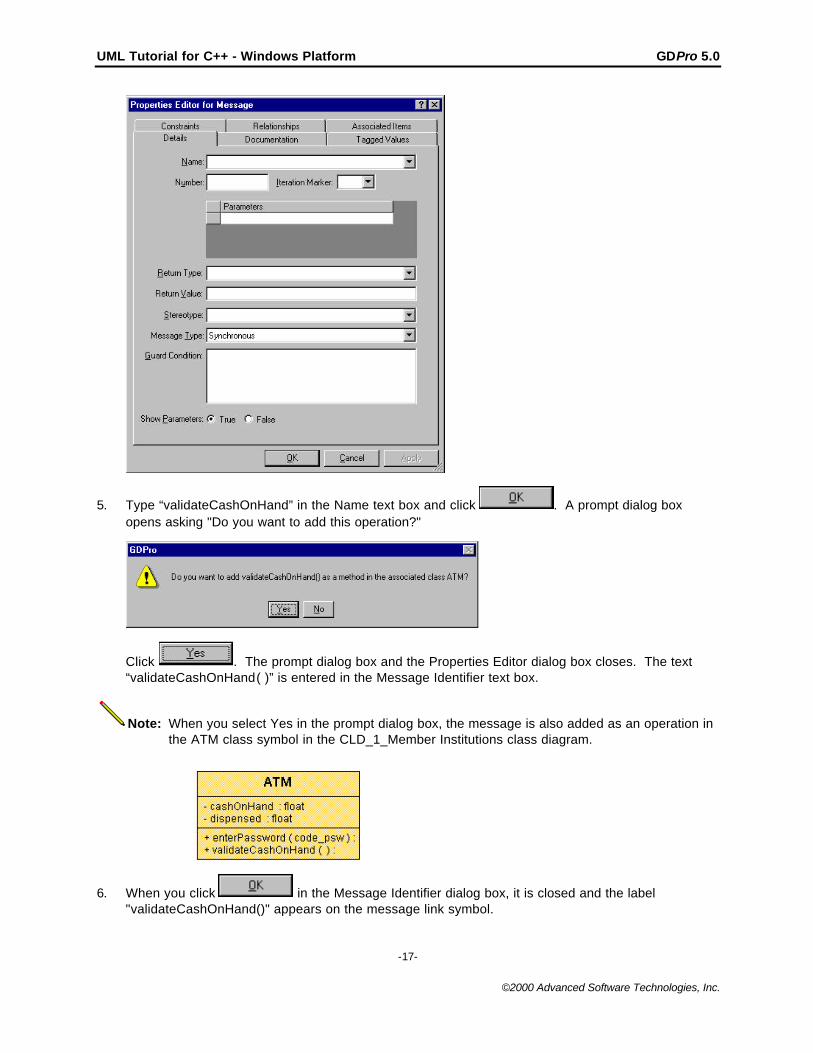
5. Type “validateCashOnHand” in the Name text box and click . A prompt dialog boxopens asking "Do you want to add this operation?"
Click . The prompt dialog box and the Properties Editor dialog box closes. The text“validateCashOnHand( )” is entered in the Message Identifier text box.
Note: When you select Yes in the prompt dialog box, the message is also added as an operation inthe ATM class symbol in the CLD_1_Member Institutions class diagram.
6. When you click in the Message Identifier dialog box, it is closed and the label"validateCashOnHand()" appears on the message link symbol.
UML Tutorial for C++ - Windows Platform GDPro 5.0
-18-
©2000 Advanced Software Technologies, Inc.
Add Message Symbols
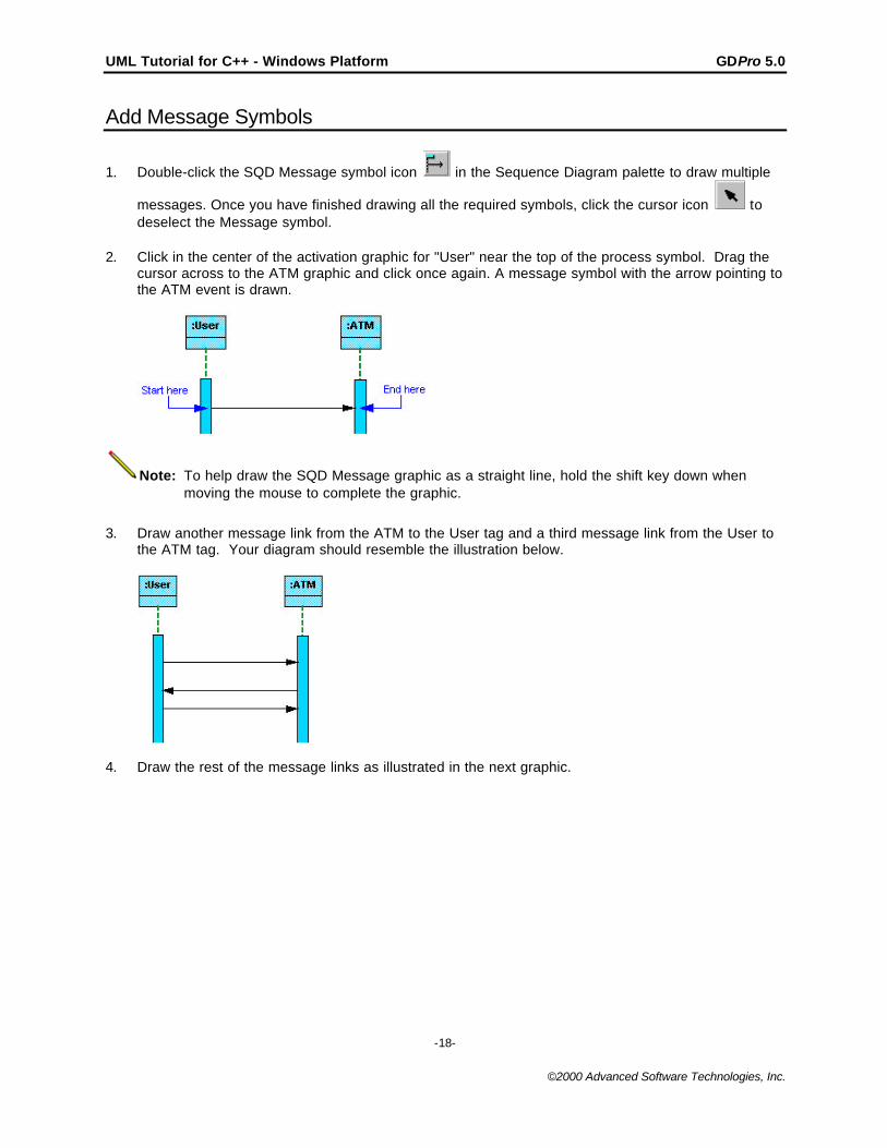
1. Double-click the SQD Message symbol icon in the Sequence Diagram palette to draw multiple
messages. Once you have finished drawing all the required symbols, click the cursor icon todeselect the Message symbol.
2. Click in the center of the activation graphic for "User" near the top of the process symbol. Drag thecursor across to the ATM graphic and click once again. A message symbol with the arrow pointing tothe ATM event is drawn.
Note: To help draw the SQD Message graphic as a straight line, hold the shift key down whenmoving the mouse to complete the graphic.
3. Draw another message link from the ATM to the User tag and a third message link from the User tothe ATM tag. Your diagram should resemble the illustration below.
4. Draw the rest of the message links as illustrated in the next graphic.
UML Tutorial for C++ - Windows Platform GDPro 5.0
-19-
©2000 Advanced Software Technologies, Inc.
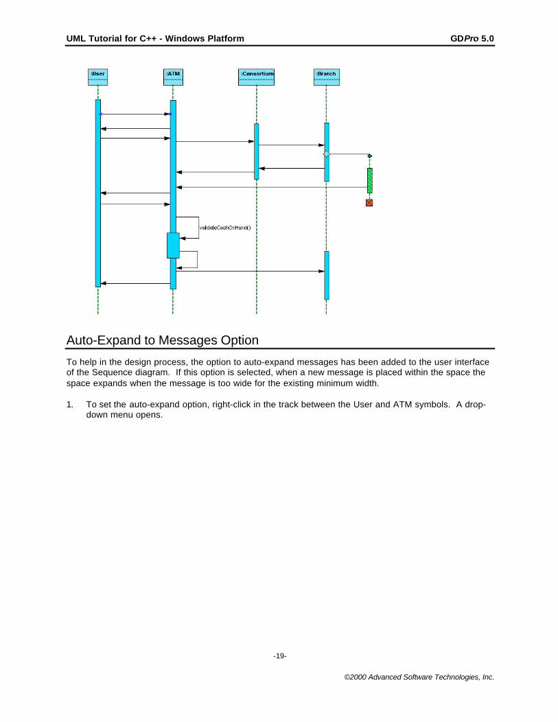
Auto-Expand to Messages Option
To help in the design process, the option to auto-expand messages has been added to the user interfaceof the Sequence diagram. If this option is selected, when a new message is placed within the space thespace expands when the message is too wide for the existing minimum width.
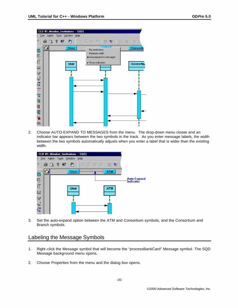
1. To set the auto-expand option, right-click in the track between the User and ATM symbols. A drop-down menu opens.
UML Tutorial for C++ - Windows Platform GDPro 5.0
-20-
©2000 Advanced Software Technologies, Inc.
2. Choose AUTO-EXPAND TO MESSAGES from the menu. The drop-down menu closes and anindicator bar appears between the two symbols in the track. As you enter message labels, the widthbetween the two symbols automatically adjusts when you enter a label that is wider than the existingwidth.
3. Set the auto-expand option between the ATM and Consortium symbols, and the Consortium andBranch symbols.
Labeling the Message Symbols
1. Right -click the Message symbol that will become the “processBankCard” Message symbol. The SQDMessage background menu opens.
2. Choose Properties from the menu and the dialog box opens.
UML Tutorial for C++ - Windows Platform GDPro 5.0
-21-
©2000 Advanced Software Technologies, Inc.
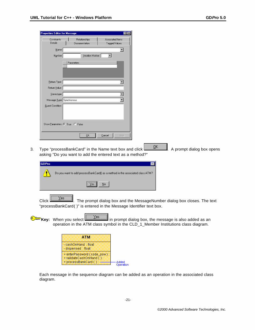
3. Type “processBankCard” in the Name text box and click . A prompt dialog box opensasking "Do you want to add the entered text as a method?"
Click . The prompt dialog box and the MessageNumber dialog box closes. The text“processBankCard( )” is entered in the Message Identifier text box.
Key: When you select in prompt dialog box, the message is also added as anoperation in the ATM class symbol in the CLD_1_Member Institutions class diagram.
Each message in the sequence diagram can be added as an operation in the associated classdiagram.
UML Tutorial for C++ - Windows Platform GDPro 5.0
-22-
©2000 Advanced Software Technologies, Inc.
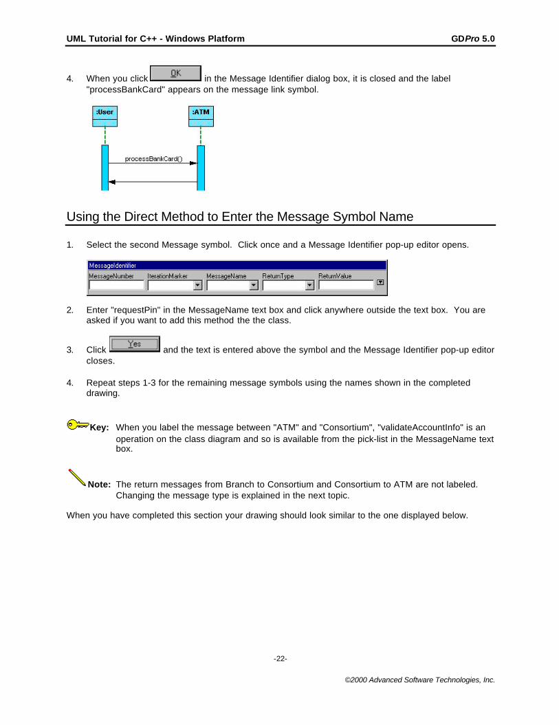
4. When you click in the Message Identifier dialog box, it is closed and the label"processBankCard" appears on the message link symbol.
Using the Direct Method to Enter the Message Symbol Name
1. Select the second Message symbol. Click once and a Message Identifier pop-up editor opens.
2. Enter "requestPin" in the MessageName text box and click anywhere outside the text box. You areasked if you want to add this method the the class.
3. Click and the text is entered above the symbol and the Message Identifier pop-up editorcloses.
4. Repeat steps 1-3 for the remaining message symbols using the names shown in the completeddrawing.
Key: When you label the message between "ATM" and "Consortium", "validateAccountInfo" is anoperation on the class diagram and so is available from the pick-list in the MessageName textbox.
Note: The return messages from Branch to Consortium and Consortium to ATM are not labeled.Changing the message type is explained in the next topic.
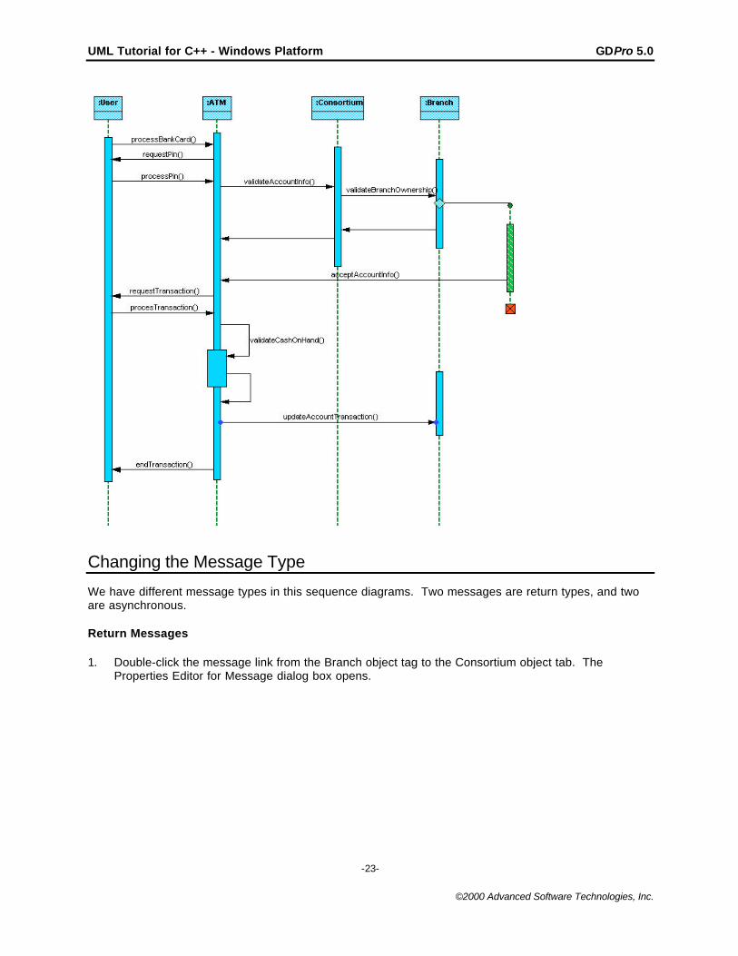
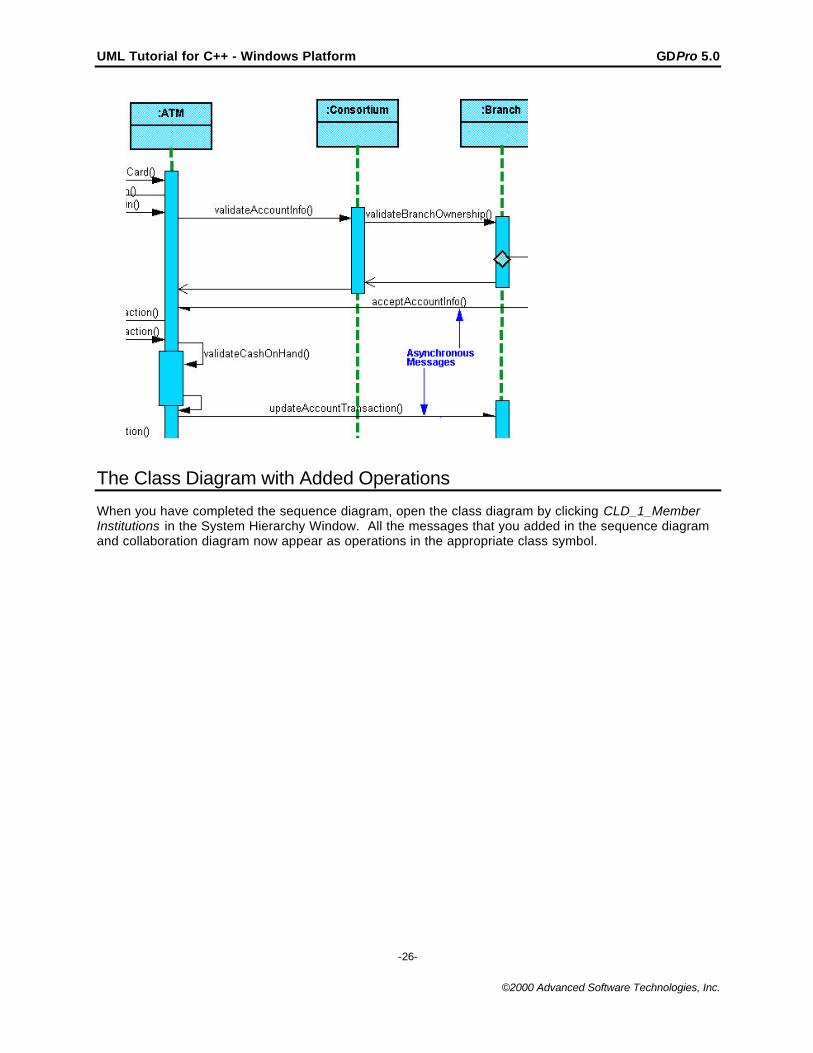
When you have completed this section your drawing should look similar to the one displayed below.
UML Tutorial for C++ - Windows Platform GDPro 5.0
-23-
©2000 Advanced Software Technologies, Inc.
Changing the Message Type
We have different message types in this sequence diagrams. Two messages are return types, and twoare asynchronous.
Return Messages
1. Double-click the message link from the Branch object tag to the Consortium object tab. TheProperties Editor for Message dialog box opens.
UML Tutorial for C++ - Windows Platform GDPro 5.0
-24-
©2000 Advanced Software Technologies, Inc.
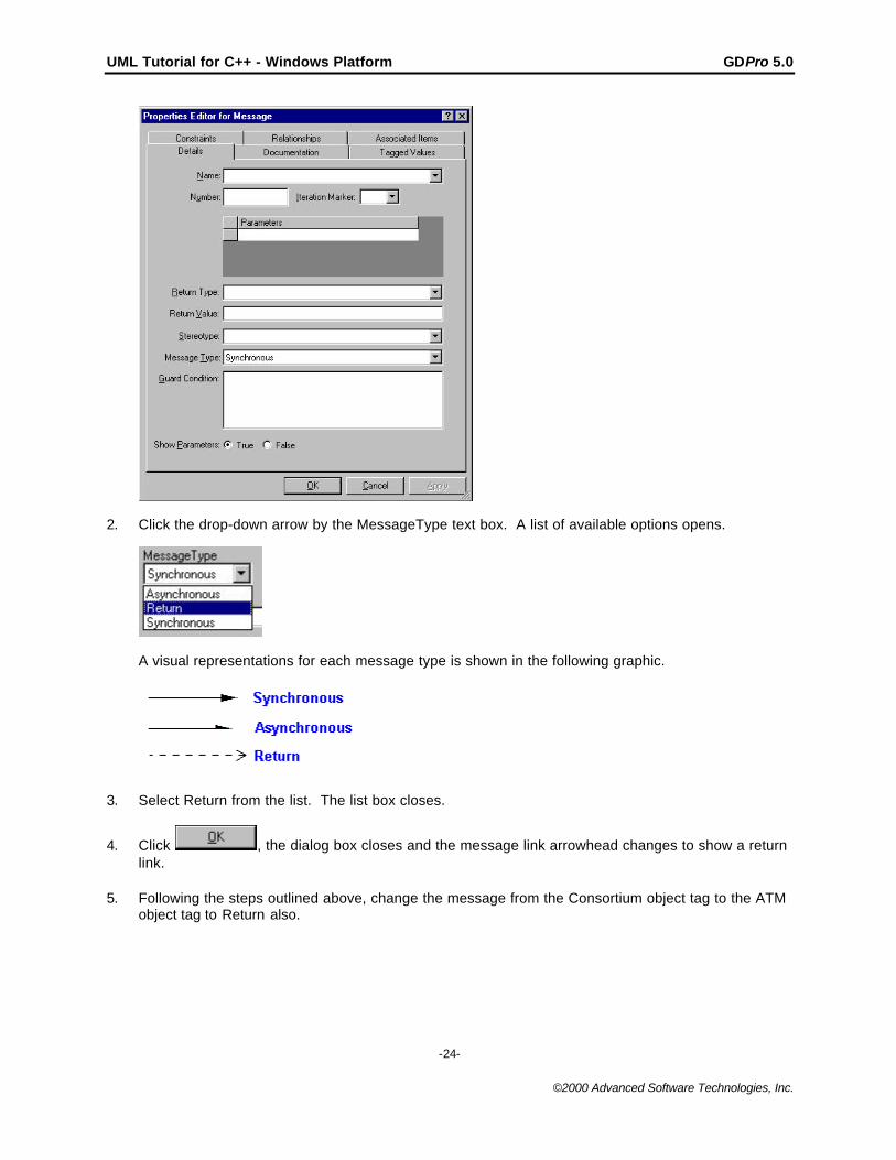
2. Click the drop-down arrow by the MessageType text box. A list of available options opens.
A visual representations for each message type is shown in the following graphic.
3. Select Return from the list. The list box closes.
4. Click , the dialog box closes and the message link arrowhead changes to show a returnlink.
5. Following the steps outlined above, change the message from the Consortium object tag to the ATMobject tag to Return also.
UML Tutorial for C++ - Windows Platform GDPro 5.0
-25-
©2000 Advanced Software Technologies, Inc.
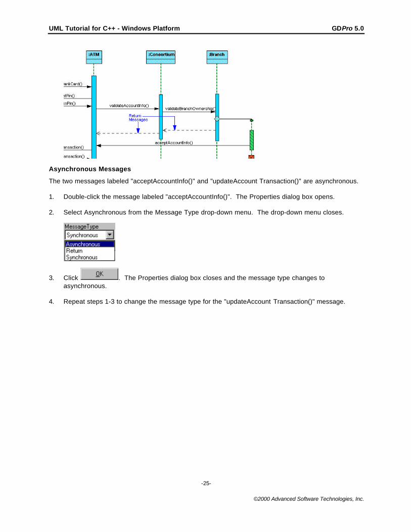
Asynchronous Messages
The two messages labeled "acceptAccountInfo()" and "updateAccount Transaction()" are asynchronous.
1. Double-click the message labeled "acceptAccountInfo()". The Properties dialog box opens.
2. Select Asynchronous from the Message Type drop-down menu. The drop-down menu closes.
3. Click . The Properties dialog box closes and the message type changes toasynchronous.
4. Repeat steps 1-3 to change the message type for the "updateAccount Transaction()" message.
UML Tutorial for C++ - Windows Platform GDPro 5.0
-26-
©2000 Advanced Software Technologies, Inc.
The Class Diagram with Added Operations
When you have completed the sequence diagram, open the class diagram by clicking CLD_1_MemberInstitutions in the System Hierarchy Window. All the messages that you added in the sequence diagramand collaboration diagram now appear as operations in the appropriate class symbol.
UML Tutorial for C++ - Windows Platform GDPro 5.0
-27-
©2000 Advanced Software Technologies, Inc.
Using the Navigate To Command
The Navigate To command appears on the Object Background menu for a class symbol or a utility classsymbol. This menu displays all symbols that the class symbol is semantically associated with. Thecommand is active only if the symbol you selected is referenced in other system diagram.
We will use the Navigate To command to return to the Sequence diagram.
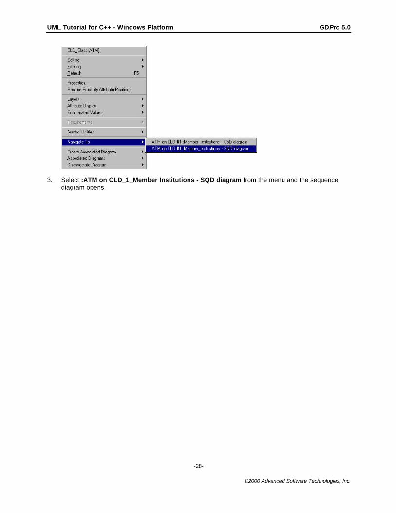
1. Right-click on the ATM class symbol. The Class (ATM) background menu opens.
2. Select the Navigate To command and a pull-right menu opens showing the ATM symbol referencedon the collaboration and sequence diagrams.
UML Tutorial for C++ - Windows Platform GDPro 5.0
-28-
©2000 Advanced Software Technologies, Inc.
3. Select :ATM on CLD_1_Member Institutions - SQD diagram from the menu and the sequencediagram opens.
Top Related