


Languages
Pages
Legal


1
Chapter 19 Radiochemical Techniques
Radiochemistry is defined as “the chemical study of radioactive elements, both
natural and artificial, and their use in the study of chemical processes” (1). Operationally
radiochemistry is defined by the activities of radiochemists, i.e., (a) nuclear analytical
methods (b) the application of radionuclides in areas outside of chemistry, such as
medicine (c) the physics and chemistry of the radioelements (d) the physics and chemistry
of high activity level matter and (e) radiotracer studies. We have dealt with several of
these topics in Chapters 4, 13, 15, and 16. In this chapter, we will discuss the basic
principles behind radiochemical techniques and some details of their application.
Because of the small amounts of material involved, the presence of radioactivity
which implies certain regulatory and safety concerns and the frequent need to deal with
short-‐lived nuclei, these techniques are not the same as ordinary chemical techniques.
Specialized techniques have evolved from the early part of the 20th century when chemistry
was a principal tool in identifying the basic nature of radioactive decay through the
extensive use of chemistry in the Manhattan Project in World War II to the present, “high
tech” character of many radiochemical manipulations. These techniques are quite
important for they are often the key to a successful experiment even though they may get
scant mention in descriptions of the experiment. Often the successful application of these
techniques requires careful, painstaking attention to detail, frequent practice to develop
the necessary manipulative skills and a thorough knowledge of the underlying scientific
principles.

2
In addition to the discussions of these topics in textbooks such as this, there
are excellent textbooks that focus primarily on radiochemistry [2-‐4].
19.1 Unique Aspects of Radiochemistry
Radiochemistry involves the application of the basic ideas of inorganic, organic,
physical and analytical chemistry to the manipulation of radioactive material. However,
the need to manipulate radioactive materials imposes some special constraints (and
features) upon these endeavors. The first of these involves the number of atoms involved
and the solution concentrations. The range of activity levels in radiochemical procedures
ranges from pCi to MCi. For the sake of discussion, let us assume an activity level, D, typical
of radiotracer experiments of 1 µCi (= 3.7 x 10⁴ dis/s = 3.7 x 10⁴ Bq), of a nucleus with mass
number A~ 100. If we assume a half-‐life for this radionuclide of 3 days, the number of
nuclei present can be calculated from the equation
!
N =D"
=(1µCi)(3.7x10⁴ dps /µCi)(3days)(24hr /day)(3600s /hr)
ln2
where λ is the decay constant of the nuclide (= ln 2/t1/2). Then
N ~ 1.4 x 10¹⁰ atoms
Mass of sample = 2.3 x 10-‐12 g
This quantity of material, if prepared as an aqueous solution of volume 1 L would have a
concentration of 10-‐14 mol/L. This simple calculation demonstrates a number of the
important features of radiochemistry, i.e., (a) the manipulation of samples involving
infinitesimal quantities of material (b) the power of nuclear analytical techniques (since 1

3
µCi is a significant, easily detectable quantity of radioactivity) and (c) in an extension of the
calculation, since the decay of a single atom might occur by α-‐particle emission (with 100%
detection efficiency), the ability to do chemistry one atom at a time.
The small number of atoms involved in some radiochemical procedures can alter
expected behavior. Although time dependent processes obeying first order kinetics are not
changed by changes in concentration, the same is not true of second order kinetics. For
example, at 10-‐2 M, isotopic exchange between U (IV) and U (VI) has a lifetime of ~ 2 hours
while at 10-‐10 M; the same lifetime is ~400 days. Another example is Np (V) which is
unstable with respect to disproportionation and yet µCi/L solutions of NpO2+ are stable.
The extreme dilution in some solutions can mean equilibrium is not reached due to kinetic
limitations. Fallout plutonium, present in the aqueous environment at concentrations of
10-‐18 – 10-‐17 M, has not reached equilibrium in over 40 years.
In addition to the limitations posed by kinetics or thermodynamics, there are certain
practical problems associated with very low solution concentrations. An important
problem is the adsorption of tracer levels of radioactivity on the surfaces of laboratory
glassware. Glass has an ion exchange capacity of 10-‐10 mol/cm2 along with a similar
number of chemisorption sites. A 100 mL beaker can thus absorb ~10-‐8 mol which is
significant if the concentration of the tracer is ≤ 10-‐6 M. One suppresses this absorption by
having high [H+] (thus blocking adsorption sites), by treating glass surfaces with non-‐
adsorbing silicone coatings or by the use of holdback carriers (see below).
Conventional analytical techniques generally operate at the ppm or higher levels. Some
techniques such as laser photo acoustic spectroscopy are capable of measuring phenomena
at the 10-‐8-‐10-‐6 mol/L level. The most sensitive conventional analytical techniques, time-‐

4
resolved laser-‐induced fluorescence and ICP-‐MS are capable of measuring concentrations
at the part per trillion level, i.e., 1 part in 1012, but rarely does one see detection
sensitivities at the single atom level as routinely found in some radioanalytical techniques.
While techniques such as ICP-‐MS are replacing the use of neutron activation analysis in the
routine measurement of ppb concentrations, there can be no doubt about the unique
sensitivity associated with radioanalytical methods.
Along with the unique sensitivity and small quantities of material associated with
radiochemistry, there is the need to comply with the regulations governing the safe use and
handling of radioactive material. This task is a primary focus in the design and execution of
radiochemical experiments and is often a significant factor in the cost of the experiment.
Because so many of these rules are site specific, they are not treated in this chapter.
There are some chemical effects that accompany high specific activities that are unique
to radiochemistry and are worth noting. Foremost among these are the chemical changes
accompanying radioactive decay. The interaction of ionizing radiation from a radioactive
source with air can result in the generation of ozone and the nitrous oxides, which can lead
to corrosion problems. Sources containing Ra or Rn produced from the decay of heavier
elements, such as U, will emanate Rn gas as the decay product of Ra. The decay products of
gaseous Rn are particulates that deposit on nearby surfaces, such as the interior of the
lungs, leading to contamination problems. In high activity aqueous solutions, one can make
various species such as the solvated electron, !aqe , hydroxyl radicals, OH•, as well as the
solvated proton, H3O+. The hydroxyl radical, OH•, is a strong oxidizing agent with
OH• + e-‐ → OH-‐ E0 = 2.8 V.

5
while the solvated electron, !aqe , is a strong reducing agent
!aqe + H+ → ½ H2 E0 = 2.77 V
Solutions involving high activity levels will change their redox properties as a function of
time. For example, all the atoms in a 100 Bq/mL (10-‐7 mol/L) solution of 239Pu will
undergo a redox change in a period of one year. In general, it is hard to keep high specific
activity solutions stable. Reagents, column materials, etc. can suffer radiation damage also.
In radiotracer studies, the self-‐decomposition (radiolysis) of 3H or 14C-‐labeled compounds
can lead to a variable concentrations and variable number of products.
Many of these effects of radioactive decay can be treated quantitatively using “G
values.” Historically the G value was defined as the number of molecules or species
decomposed or formed per 100 eV of absorbed energy. A newer (SI) definition of the G
value is the number of moles of molecules or species formed or decomposed per Joule of
energy absorbed. (Note that 1 mol/J = 9.76 x 10⁶ molecules/100 eV). G values depend on
the radiation and the medium being irradiated and its physical state. Table 19-‐1 shows
some typical G values for the irradiation of neutral liquid water
Table 19-‐1 Product Yields (µmol/J) in irradiated neutral water Radiation G(-‐H2O) G(H2) G(H2O2) G(eaq) G(H•) G(•OH) γ and fast electrons
0.43 0.047 0.073 0.062 0.28 0.0027
12 MeV α-‐particles
0.29 0.12 0.11 0.028 0.056 0.007

6
The actual final products of radiolysis are the result of a complex set of chemical reactions.
Detailed quantitative estimates of product yields are therefore more complicated and
beyond the scope of this book. The reader is referred to other textbooks that discuss how
these estimates are made. [5]
Radioactive decay also causes chemical transmutations. The daughter nucleus in α
or β-‐decay is a different chemical element than the mother nucleus, but it is in the same
chemical environment as the mother nucleus. Change of oxidation state or bonding is a
possibility.
In alpha decay, one expects all chemical bonds to the decaying atom to be broken as
the recoil energy of the daughter nucleus exceeds chemical bond energies. Surprisingly,
the oxidation state of the daughter nucleus is frequently that of the parent nucleus after all
electronic and atomic re-‐arrangements have taken place. (An obvious exception is when
the daughter cannot exhibit the parent’s oxidation state such as the α-‐decay of U(VI) as
UO2++. where the daughter does not exhibit the +6 oxidation state.)
In β-‐ decay, especially for low energy β-‐ emitters like 14C or 3H, the effects on
chemical bonding are modest. So if we have
14CH4 → 14NH4+
the β-‐ decay can be considered an oxidizing process. In fact, β-‐ decay (of 83SeO42-‐ and
242AmO2+) was used successfully to prepare new higher oxidation states (of 83BrO4-‐ and
242CmO22+) of some elements. In electron capture or internal conversion decay, there are
massive rearrangements of the atomic electrons, which makes these considerations more
complicated.

7
Some tracers (usually cations) in solution behave as colloids rather than true
solutions. Such species are termed radiocolloids and are aggregates of 103 – 107 atoms,
with a size of the aggregate in the range 0.1 – 500 nm. They are quite often formed during
hydrolysis, especially of the actinides in high oxidation states. One can differentiate
between real radiocolloids and pseudo-‐colloids, in which a radionuclide is sorbed on an
existing colloid, such as humic acid or Fe(OH)3. Formation of real colloids can be prevented
by using solutions of low pH or by addition of complexing agents. The chemical behavior
of these radiocolloids is difficult to predict, as the systems are not at equilibrium.
There are certain unique features to the chemical separations used in
radiochemistry compared to those in ordinary analytical chemistry that are worth noting.
First of all, high yields are not necessarily needed, provided the yields of the separations
can be measured. Emphasis is placed on radioactive purity, expressed as decontamination
factors rather than chemical purity. Chemical purity is usually expressed as the ratio of the
number of moles (molecules) of interest in the sample after separation to the number of all
the moles (molecules) in the sample. Radioactive purity is usually expressed as the ratio of
the activity of interest to that of all the activities in the sample. The decontamination factor
is defined as the ratio of the radioactive purity after the separation to that prior to the
separation. Decontamination factors of 105 – 107 are routinely achieved with higher values
possible. In the event that the radionuclide(s) of interest are short-‐lived, then the time
required for the separation is of paramount importance, as it does no good to have a very
pure sample in which most of the desired activity has decayed during the separation.
As indicated above, frequently the amount of material involved in a radiochemical
procedure is quite small. To obviate some of the difficulties associated with this, a

8
weighable amount (~mg) of inactive material, the carrier, is added to the procedure at an
early stage. It is essential that this carrier and the radionuclide (tracer) be in the same
chemical form. This is achieved usually by subjecting the carrier + tracer system to one or
more redox cycles prior to initiating any chemical separations to insure that the carrier and
tracers are in the same oxidation state.
Carriers frequently are stable isotopes of the radionuclide of interest, but they need
not be. Non-‐isotopic carriers are used in a variety of situations. Scavengers are non-‐
isotopic carriers used in precipitations that carry/incorporate other radionuclides into
their precipitates indiscriminately. For example, the precipitation of Fe (OH)3 frequently
carries, quantitatively, many other cations that are absorbed on the surface of the
gelatinous precipitate. Such scavengers are frequently used in chemical separations by
precipitation in which a radionuclide is put in a soluble oxidation state, a scavenging
precipitation is used to remove radioactive impurities and then the nuclide is
oxidized/reduced to an oxidation state where it can be precipitated. In such scavenging
precipitations, holdback carriers are introduced to dilute the radionuclide atoms by
inactive atoms and thus prevent them from being scavenged.
It is certainly possible, although usually more difficult, to do carrier-‐free
radiochemistry in which one works with the radionuclides in their low, tracer-‐level
concentrations. Such carrier-‐free radiochemistry is used when the presence of the
additional mass of carrier atoms would lead to problems of sample thickness (alpha-‐
emitters), biological side effects (radiopharmaceuticals) or where high specific activities
are needed (synthesis of labeled compounds). (Formally, specific activity is the activity
per mass unit, such as mCi/mg or µCi/µmol, etc.)

9
19.2 Availability of Radioactive Material
To do radiochemistry, one needs radioactive materials. As indicated in Chapter 3,
radionuclides may be classified as primordial (remnants of nucleosynthesis), cosmogenic
(being continuously generated by the action of cosmic rays with the upper atmosphere) or
anthropogenic (made by man). Most of the radionuclides used in radiochemistry are of the
latter type, i.e., made artificially in response to perceived needs. In Table 4-‐1, we
summarized the commonly used radionuclides and their method of preparation. As
indicated in this table, a large number of these nuclides can be made by neutron irradiation
in a nuclear reactor using (n,γ) reactions. Such nuclei are, of course, not carrier-‐free, are
largely β-‐ emitters and have low specific activities. Charged particle induced reactions,
using cyclotrons, are used to synthesize neutron-‐deficient nuclei, that decay by EC or β+
emission. The short-‐lived nuclei used in PET or other procedures in nuclear medicine fall
into this category.
The transuranium nuclei are a special class of radionuclides, being made by both
reactor irradiation and production in charged particle accelerators. In Table 19-‐2, we
summarize the properties and available amounts for research in the United States by
qualified individuals.
TABLE 19.2 Availability of Transuranium Element Materials
Nuclide t1/2 Decay Mode Amounts Available Specific Activity (dpm/µg)
237Np 2.14 x 10⁶ years α, SF(10-‐10%) kg 1565. 238Pu 87.7 years α, SF(10-‐7%) kg 3.8 x 10⁷ 239Pu 2.41 x 10⁴ years α, SF(10-‐4%) kg 1.38 x 10⁵ 240Pu 6.56 x 10³ years α, SF(10-‐6%) 10-‐50 g 5.04 x 10⁶ 241Pu 14.4 years β, α(10-‐3%) 1-‐10 g 2.29 x 10⁸ 242Pu 3.76 x 10⁵ years α, SF(10-‐3%) 100 g 8.73 x 10³ 244Pu 8.00 x 10⁷ years α, SF(0.1%) 10-‐100 mg 39.1

10
241Am 433 years α, SF(10-‐10%) kg 7.6 x 10⁶ 243Am 7.38 x 10³ years α, SF(10-‐8%) 10-‐100 g 4.4 x 10⁵ 242Cm 162.9 days α, SF(10-‐5%) 100 g 7.4 x 10⁹ 243Cm 28.5 years α, (0.2%) 10-‐100 mg 1.15 x 10⁸ 244Cm 18.1 years α, SF(10-‐4%) 10-‐100g 1.80 x 10⁸ 248Cm 3.40 x 10⁵ years α, SF(8.3%) 10-‐100 mg 9.4 x 10³ 249Bk 320 days β,α(10-‐3%),
SF(10-‐8%) 10-‐50 mg 3.6 x 10⁹
249Cf 350.6 years α, SF(10-‐7%) 1-‐10 mg 9.1 x 10⁶ 250Cf 13.1 years α, SF(0.08%) 10 mg 2.4 x 10⁸ 252Cf 2.6 years α, SF(3.1%) 10-‐1000 mg 1.2 x 10⁹ 254Cf 60.5 days SF, α(0.3%) µg 1.9 x 10¹⁰ 253Es 20.4 days α, SF(10-‐5%) 1-‐l0mg 5.6 x 10¹⁰ 254Es 276 days α 1-‐5 µg 4.1 x 10⁹ 257 Fm 100.5 days α, SF(0.2%) 1 pg 1.1 x 10¹⁰ One should also note that while large quantities of 239Pu are available, it is classified as a
Special Nuclear Material because of its use in weaponry and very strict regulations govern
the possession and use of this nuclide (along with 233U and 235U).
19.3 Targetry
As indicated above, a combination of reactor and cyclotron irradiations is used to
prepare most radionuclides. While many of these radionuclides are available
commercially, some are not. In addition, nuclear structure, nuclear reactions and heavy
element research require accelerator or reactor irradiations to produce short-‐lived nuclei
or to study the dynamics of nuclear collisions, etc. One of the frequent chores of
radiochemists is the preparation of accelerator targets, and samples for reactor irradiation.
It is this chore that we address in this section.
The first question to be addressed in preparing accelerator targets or samples for
irradiation is the question of impurities and/or other chemical constituents of the sample.
For neutron irradiation, one generally prefers metals or non-‐activable inorganic salts. The
salts usually include nitrates, sulfates, etc., but not halides (especially chlorides due to the
11
activation of chlorine) nor sodium nor potassium salts. In general, one avoids materials
that undergo radiolysis although it is possible, with suitable precautions, to irradiate
materials, such as gasoline, oil, and other flammable materials in reactors. Liquid samples
can be irradiated in reactors easily, but one must generally pay attention to pressure
buildup in the irradiation container due to radiolytic decomposition of water. Unless
purged with nitrogen, water will contain dissolved argon, which will activate to form 41Ar,
and the radioactive atoms will be released upon opening the irradiation container. For
irradiations of a few hours in moderate flux (~ 1012 n/cm2sec) reactors, the samples to be
irradiated may be heat sealed in polyethylene vials, usually using double encapsulation.
For long irradiations or higher fluxes (~1015 n/cm2sec) encapsulation in quartz is needed.
One never uses Pyrex or other boron-‐containing glasses due to their high cross sections for
neutron absorption. When irradiating larger samples, one must pay attention to self-‐
shielding in the samples. For example, the flux reduction in a 0.5 mm Au foil is about 27%
due to self-‐absorption. However, in irradiations of most liquid samples or geological
samples, these self-‐absorption corrections can be neglected.
Preparation of the targets for charged particle irradiations requires more effort due
to the large rate of energy loss of charged particles in matter. In general, material to be
irradiated must be in vacuum, thus making the irradiation of liquids and gases more
difficult. Solids must be in the form of thin foils or deposits on thin backing material.
Typical backing materials are carbon, aluminum, beryllium, and titanium. The typical
measure of thickness of accelerator targets is in units of areal density (mass/unit area, i.e.,
mg/cm2). The thickness expressed in units of areal density (mg/cm2) is the linear
thickness (cm) multiplied by the density (mg/cm3). One can weigh very thin samples and
12
determine their area and thus their areal density. Typical thicknesses of accelerator
targets are ~0.1-‐ 5 mg/cm2, but depend, of course, on the rate of energy loss of the
irradiating ion in passing through the target material. Target backings are frequently 10 -‐
100µg/cm2. Such thicknesses qualify as being “thin”, i.e., easily breakable and require
special preparation techniques.
Because of the high rate of energy loss of charged particles in matter, one
must pay attention to cooling the targets or in some way, dissipating the energy deposited
in the target material as the beam nuclei pass through it. For example, consider the
irradiation of a 0.5 mg/cm2 208Pb target by 450 MeV 86Kr ions. Each Kr ion passing through
the target deposits ~8.1 MeV in the target. If the Kr beam intensity is 1 particle-‐µa (6.24 x
1012 ions/sec), then the rate of energy deposit in the target is ~5 x 10¹³ MeV/s ≈ 8.1 J/s. If
the foil has an area of 2 cm2, it would have a mass of 1 g. The specific heat of Pb is 0.130
J/g/°C. Thus, in the absence of any cooling, the temperature of the target would rise
8.1°/sec and the foil would soon melt. Since the foil will generally be in vacuum, without
further intervention, it would only cool radiatively, which will not suffice. Heat transfer
from such a foil can occur by clamping it to the front of a cooled block (remembering now
that the entire beam energy will be dumped into the cooling block). Alternately a jet of a
light gas such as helium can be used to cool the backside of the foil or the particle beam can
be spread over a larger area foil thus reducing the temperature increase.
Over the years, a number of specialized techniques have been developed for the
preparation of accelerator targets. These techniques are also used in the preparation of
thin sources for counting, such as those used in alpha or beta spectroscopy. The first and
simplest technique for depositing a target material on a backing foil is by evaporation of a
13
solution of the desired material on the foil. Generally this is a poor choice as the solute
tends to deposit at the edges of the dried droplet, leading to variations of up to a factor of
100 in thickness over the area of the deposit. Uniformity can be improved by using a
spreading agent such as insulin to coat the surface of the backing material prior to
evaporation.
A method that was widely used in the past is electrospraying. A solution of the
nuclide to be deposited is prepared in a volatile, non-‐conducting liquid like acetone,
alcohol, etc. A capillary is drawn out to a fine point such that no liquid can escape under
normal conditions and filled with the solution. A fine wire is threaded though the capillary
to within a few mm of the tip. A high voltage (3 – 10 KV) is applied between the wire in the
tube and the backing material on which the deposit is to be made. One gets a spray of
charged drops that are collected on the backing material, placed ~ 1 cm from the capillary.
The volatile solvent evaporates leaving a uniform film. The deposit can be calcined.
Another widely used technique for preparing thin deposits on a backing material is
electrodeposition. Two types of electrodeposition are commonly used: (a) the direct
deposit of a metal on a cathodic surface by reduction or (b) precipitation of a cationic
species in an insoluble form on an electrode. This latter technique is widely used to deposit
actinides and lanthanides. A 10 – 100 µL aqueous solution of the actinide or lanthanide is
mixed with ~15 mL of isopropyl alcohol and placed in a plating cell (Figure 19-‐1). The
inorganic material forms a positively charged complex in which the inorganic molecule is
surrounded by a cluster of solvent molecules. A high voltage (~ 600 V) is applied between a
rotating anode and the cathodic backing material. The positively charged complex is
attracted to the cathode of the cell. The lanthanides/ actinides precipitate as hydrous

14
oxides near the cathode which is a region of high pH. The alcohol is withdrawn from the
cell and the deposit is dried and calcined. This technique is called molecular plating
because the film is not that of the metal but some molecular form of it. Deposit thicknesses
are restricted to < 0.5 mg/cm2 but the deposition is rapid and quantitative and allows the
use of active metals such as Al as backing foils. [6]
Figure 19-‐1 Schematic diagram of molecular plating cell. From Wang, Willis, and Loveland.
Vacuum deposition is a well-‐established technique for making very uniform deposits
of non-‐refractory materials on a backing material. In Figure 19-‐2, we show a typical simple
evaporation apparatus.

15
Figure 19-‐2 Simple schematic diagram of a vacuum deposition apparatus. From Wang,
Willis and Loveland.
The material to be evaporated is placed in a sample holder. Frequently these sample
holders are indented strips of W, Ta, or Mo, or wire baskets of the same metals, or carbon
crucibles. These sample holders can be heated resistively by passing a large current
through them, thus melting and then volatilizing the material. Alternatively the sample
holder can be bombarded by low energy electrons to heat the sample. The entire process
takes place in vacuum. Under reduced pressure, most materials melt readily and then
evaporate. The substrate on which the vapors from the heated sample condense is placed
some distance from the source of evaporating material. The area of the deposit may be
defined by collimators. The deposits produced by vacuum evaporation are very uniform,
but the process is not efficient, with < 1% of the sample material being deposited in typical
16
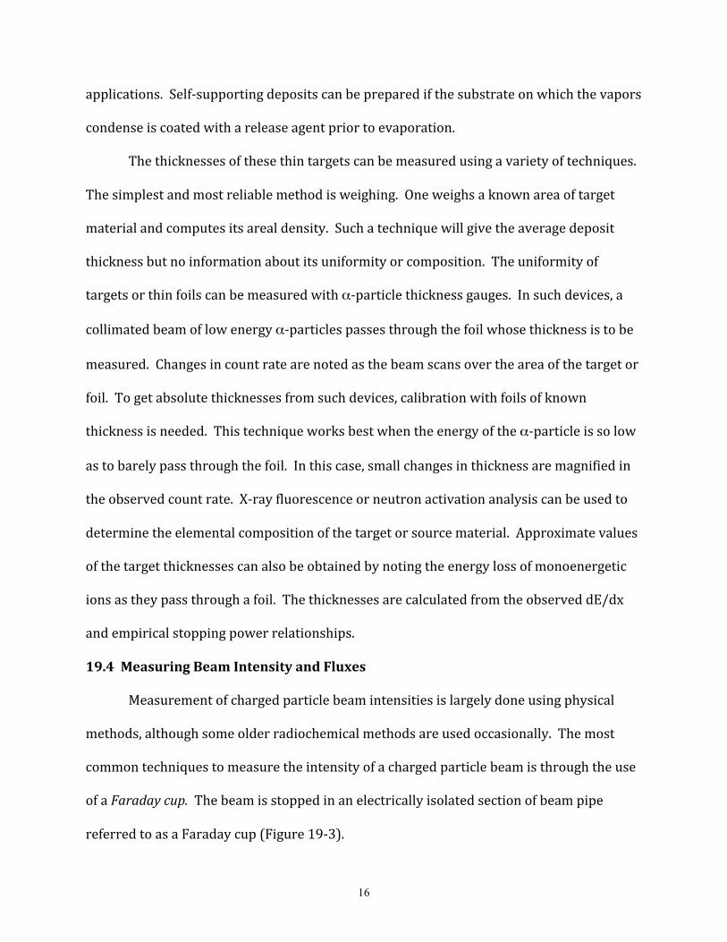
applications. Self-‐supporting deposits can be prepared if the substrate on which the vapors
condense is coated with a release agent prior to evaporation.
The thicknesses of these thin targets can be measured using a variety of techniques.
The simplest and most reliable method is weighing. One weighs a known area of target
material and computes its areal density. Such a technique will give the average deposit
thickness but no information about its uniformity or composition. The uniformity of
targets or thin foils can be measured with α-‐particle thickness gauges. In such devices, a
collimated beam of low energy α-‐particles passes through the foil whose thickness is to be
measured. Changes in count rate are noted as the beam scans over the area of the target or
foil. To get absolute thicknesses from such devices, calibration with foils of known
thickness is needed. This technique works best when the energy of the α-‐particle is so low
as to barely pass through the foil. In this case, small changes in thickness are magnified in
the observed count rate. X-‐ray fluorescence or neutron activation analysis can be used to
determine the elemental composition of the target or source material. Approximate values
of the target thicknesses can also be obtained by noting the energy loss of monoenergetic
ions as they pass through a foil. The thicknesses are calculated from the observed dE/dx
and empirical stopping power relationships.
19.4 Measuring Beam Intensity and Fluxes
Measurement of charged particle beam intensities is largely done using physical
methods, although some older radiochemical methods are used occasionally. The most
common techniques to measure the intensity of a charged particle beam is through the use
of a Faraday cup. The beam is stopped in an electrically isolated section of beam pipe
referred to as a Faraday cup (Figure 19-‐3).
17
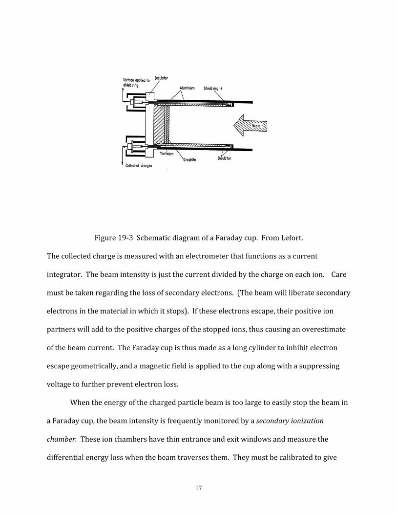
Figure 19-‐3 Schematic diagram of a Faraday cup. From Lefort.
The collected charge is measured with an electrometer that functions as a current
integrator. The beam intensity is just the current divided by the charge on each ion. Care
must be taken regarding the loss of secondary electrons. (The beam will liberate secondary
electrons in the material in which it stops). If these electrons escape, their positive ion
partners will add to the positive charges of the stopped ions, thus causing an overestimate
of the beam current. The Faraday cup is thus made as a long cylinder to inhibit electron
escape geometrically, and a magnetic field is applied to the cup along with a suppressing
voltage to further prevent electron loss.
When the energy of the charged particle beam is too large to easily stop the beam in
a Faraday cup, the beam intensity is frequently monitored by a secondary ionization
chamber. These ion chambers have thin entrance and exit windows and measure the
differential energy loss when the beam traverses them. They must be calibrated to give
18
absolute beam intensities. If the charged particle beam intensity is very low (< 106
particles/sec), then individual particles can be counted in a plastic scintillator detector
mounted on a photomultiplier tube.
When performing irradiations with neutrons or high energy protons, it is common
to measure the beam intensity using a monitor reaction. A thin foil of a pure element is
placed in the irradiating flux near the target and irradiated simultaneously with the target.
Then both the reaction products from the target foil and the monitor foil are collected and
counted. The flux is calculated using a known cross section for the monitor reaction.
Assuming that the monitor and target foils are exposed to the same irradiating flux,
we have, for the activity of the monitor and target foils, Amon and Atgt, respectively, at the
end of the irradiation
Atgt = Nrσrφ(1-‐e-‐λrt)
Amon = Nmσmφ(1-‐e-‐λmt)
where Ni, σi, λi are the number of target atoms, cross section and product decay constant
for the ith reaction. The cross section for the reaction of interest, σr, is
!
" r =Atgt
Nr#(1$ e$%r t )
Substituting for φ in terms of the monitor reaction, we get
( )( ) mont
t
mon
r
mon
tgtr r
m
ee
NN
A
A!!
"
"
•#
#••=
#
#
11
If the irradiation is long enough to produce saturation activities in both the target and
monitor foils, we have
monmon
r
mon
tgtr N
NA
A!! ••=

19
For high energy protons, typical monitor reactions are 27Al →24Na, 27Al→22Na,
12C→7Be, 27Al→18F, 197Au → 149Tb, and 12C(p,pn)11C where the arrows indicate a complex
set of reaction paths leading from the initial nucleus to the product nucleus. Care must be
taken in the case of reactions producing 24Na or 11C to correct for secondary neutron-‐
induced reactions that produce these nuclides. In high energy reactions, the loss of recoils
from the monitor or target foils can be corrected for by irradiating a stack of three identical
foils and only counting the center foil. The forward-‐going recoils from the first foil enter
the second foil and compensate for its forward recoil loss. The backward recoils from the
third foil enter the second foil and compensate for its backward recoil loss.
The measurement of neutron fluxes by foil activation is more complicated because
the neutrons are not monoenergetic and the monitor cross sections are energy dependent.
The simplest case is monitoring slow neutron fluxes. Radiative capture (n,γ) reactions have
their largest cross sections at thermal energies and are thus used in slow neutron monitors.
Typical slow neutron activation detectors are Mn, Co, Cu, Ag, In, Dy and Au. Each of these
elements has one or more odd A isotopes with a large thermal (n,γ) cross section, ~ 1-‐2000
b. The (n,γ) reaction products have half-‐lives ranging from minutes to hours. The
activation cross sections generally vary as 1/v although some nuclides have resonances in
the capture cross sections for neutrons with energies between 1 and 1000 eV. A correction
for such resonance capture can be made by irradiating the monitor foils with and without a
Cd cover. The (n,γ) cross section for Cd below 0.4 eV is very large and is small for energies
above this and thus very few low energy neutrons penetrate the Cd cover. Irradiation of a
foil without a Cd cover will cause reactions induced by both thermal and resonance
neutrons, while the Cd-‐covered foil will just respond to resonance neutrons.

20
One can also use so-‐called “threshold monitor detectors” where the activating
reaction has an energy threshold, such as the (n,α) , (n,p), (n,2n) reactions. By exposing a
set of threshold detectors (involving different reactions with different thresholds) to a
neutron flux, one can determine the relative amounts of different energy groups in the
neutron spectrum. Further information about the use of activation detectors to measure
neutron fluxes can be found in the textbooks by Knoll [7] and Tsoulfanidis [8].
19.5 Recoils, Evaporation Residues (EVRs) and Heavy Residues
In a nuclear reaction, the momentum transfer to the struck nucleus is not negligible.
If an A=100 nucleus fuses completely with a 100 MeV α-‐particle projectile, the kinetic
energy of the completely fused system is ~ 4 MeV. A similar fusion of an A=100 nucleus
with a 100 MeV 16O projectile will give the completely fused system an energy of 13.8 MeV.
These energies are extremely large compared to chemical bond energies. Depending upon
the position in the target foil where the nuclear reaction takes place, some or all of these
recoiling nuclei may escape from the target foil. These recoil nuclei, which are usually
radioactive, can be collected or studied using physical or radiochemical techniques. In
reactor irradiations, these recoils produce “contamination” on the surface of irradiation
containers.
When these heavy recoil nuclei are the result of a complete fusion of the projectile
and target nuclei, they are usually called evaporation residues because they result from a
de-‐excitation of the primary complete fusion product by particle evaporation (emission).
In intermediate energy and relativistic nuclear collisions, the momentum transfer to the
target nucleus is much less and the energy of the recoiling nucleus is ~5-‐100 keV/nucleon.
Such recoils are usually called heavy residues*.

21
* It should be noted that in this discussion we are tacitly assuming “normal” reaction kinematics with the lighter nucleus being the projectile (that is in motion) and the heavier collision partner being at rest in the laboratory system, In reactions studied using “inverse kinematics” with a heavier projectile striking a lighter target nucleus, the momentum of the recoiling heavy nucleus is approximately the same as that of the projectile nucleus. In inverse kinematics reactions, the energies of the EVRs or heavy residues are large and their spatial and energy distribution is compressed accordingly. Collection of these recoils is relatively easy but high resolution is needed because of the spatial and energy compression.
There are a variety of ways to collect the recoiling heavy products of a nuclear
reaction. One radiochemical technique is the so-‐called “thick target-‐thick catcher method.”
Here a target foil whose thickness exceeds the average range of the recoils is surrounded
by catcher foils of C or Al or some other material whose thickness exceeds the range of the
recoiling product nucleus which will not lead to production of the nuclide of interest. The
average range of the recoiling product, <R>, (which can be related to its total kinetic
energy) is given as
!
< R >=NcW
Nc + Nw
where Nc is the number of recoils which escape from the target, Nw is the number that
remains in the target and W is the thickness of the target. The fraction of product nuclei
that recoil into the forward catcher foil, F, and the fraction that recoil into the backward
catcher foil, B, can be used to deduce something about the relative velocity imparted to the
recoiling nucleus by the initial projectile-‐target interaction, v, and the isotropic velocity
kick, V, given to it by successive momentum kicks by sequential particle emission.
Formally we define the quantity η where η=v/V. η can be related to F and B
1)/(1)/(
2/1
2/1
+
!=
BFBF
"

22
So the thick target-‐thick catcher method can lead to crude information about the
kinematics of the nuclear reaction under study [9]. This technique can be used to
advantage in the study of intermediate energy and relativistic nuclear collisions where the
energy of the heavy residues is low (~10-‐100 keV/nucleon). In this case, most of the
residues stop in the target foil and cannot be studied any other way.*
For the study of recoils in low energy and some intermediate energy reactions, one
can use a thin target ( < 0.5 mg/cm2). The energy loss of the recoils in emerging from these
targets is negligible or calculable and tolerable. With thin target irradiations, one can stop
the recoiling nuclei in a catcher foil, which can be counted, perhaps after intervening
chemical separations to isolate the products of interest. The “catcher foil” can take the
form of a tape or rotating wheel that can rapidly transport the activity to a remote, low
background location for counting. Alternatively, the “catcher foil” can take the form of a
stack of thin foils that stop the products. These foils, upon disassembly and counting, can
be used to construct a differential range distribution for products of interest. Catcher foils
or stacks of foils can be mounted at various angles with respect to the incident beam and
can be used to measure product angular or energy distributions. These catcher foil
techniques are now only used to study reactions with very low cross sections where their
use provides a high detection sensitivity.
The “catcher foil” can take the form of a jet of rapidly moving gas, a helium jet. The
atoms produced in a nuclear reaction recoil out of a thin target and are stopped in -‐1 atm
of helium gas in the target chamber. The gas contains an aerosol, typically an alkali halide,
to which charged reaction product recoils attach themselves via van der Waals forces. The
helium gas (and the aerosol particles) escapes through a small orifice to a vacuum
23
chamber, with the gas achieving sonic velocity. The gas and aerosol can be transported for
substantial distances in thin capillary tubes. The aerosol particles (and the attached
atoms) are collected by allowing the gas stream to strike a collector surface. The resulting
deposit can be counted directly or dissolved for further chemical processing. The aerosol
loaded gas stream (jet) can also be used to transport the atoms through a thin capillary a
distance of several meters in a few seconds. If the carrier gas is extremely pure helium gas,
then the residues will remain ionized and can be collected using electrostatic devices. A
number of systems have been developed and used to collect reaction products as ions
without involving aerosols in the carrier gas.
The principal limitation of the isolation devices discussed previously (tapes, jets, et
cetera) is that the reaction product must be stopped and mechanically transported to
radiation detectors before product identification can occur. This restricts their use to
studies of nuclei whose t1/2 > 1 ms. For detection and identification of species whose t1/2 <
1 ms, one employs instruments based upon direct magnetic and/or electrostatic deflection
of target recoils. The most spectacularly successful of these devices is the velocity filter
SHIP (Figure 15-‐7). Evaporation residues produced in compound nucleus reactions
emerge from the target and pass through a thin carbon foil which has the effect of
equilibrating the ionic charge distribution of the residues. The ions then pass through two
filter stages consisting of electric deflectors, dipole magnets, and a quadruple triplet for
focusing. The solid angle of acceptance of the separator is 2.7 msr with a separation time
for the reaction products of ~ 2 µs with a total efficiency of collecting evaporation residues
of ~ 20% for Aproj > 40. Since complete fusion evaporation residues have very different
velocities and angular distributions than target-‐like transfer and deep-‐inelastic products (a

24
factor of ~ 2 difference in velocity between transfer products and evaporation residues)
and beam nuclei, the separator with its ± 5% velocity acceptance range and narrow
angular acceptance very effectively separates the evaporation residues from the other
reaction products and the beam. Following separation, the residues pass through a large
area time of flight detector and are stopped in an array of position-‐sensitive detectors.
From their time of flight and the energy deposited as they stop in the position sensitive
detectors, a rough estimate of their mass may be obtained (dA/A ~0.01). The final genetic
identification of the residues is made by recording the time correlations between the
original position signals from the detectors and subsequent decay signals from the same
location (due to alpha or spontaneous fission decay) and/or signals from γ or x-‐ray
detectors placed next to the position-‐sensitive detector. This device for studying heavy
element evaporation residues was used in the discovery of elements 107-‐112 (Chapter
15).
An alternate method of recoil collection and separation from other reaction
products is the gas-‐filled separator. Unlike the vacuum separators SHIP at GSI or the
Fragment Mass Analyzer at ANL that can only accept a limited range of charge-‐to mass
ratios, a gas-‐filled separator is a magnetic separator that is filled with a low pressure (~ 1
torr) gas (usually H or He). Evaporation residues emerging from the target undergo
charge charging collisions in the gas and quickly equilibrate to a common average charge
state. The change in recoil charge states with gas pressure in a gas-‐filled magnet is shown
in Figure 19-‐4. At a pressure ~ 1 torr, all recoils have a common average charge state.
This charge state will differ from the charge of the projectile nuclei or other reaction
products. This charge equilibration allows a

25
Figure 19-‐4 Changes in focal plane distributions in a gas-‐filled magnet for the reaction
involving 350 MeV 58Ni ions. From M. Paul, Nucl. Instru. Meth. A277, 418 (1989)
very efficient collection of the recoils but with a loss of the detailed mass selection
obtained in vacuum separators like SHIP that use both electric and magnetic fields for
separation. The appropriate magnetic rigidity to collect a given product nuclide with a gas-‐
filled separator can be roughly described by the simple formula

26
where m, Z, and v are the mass, atomic number and velocity of the recoiling ion,
respectively and v0 is the Bohr velocity, 2.18 x 10⁶ m/s. (In reality, qave is a sensitive
function of the atomic structure of the recoiling ion and the gas [10]). The magnetic
rigidity is proportional to the recoil velocity so that recoils of the same charge and velocity
are focused. The primary beam is separated from the recoils right after the target by a
dipole bending magnet followed by two quadrupole magnets that focus the beam onto the
focal plane. For the study of heavy element production reactions, collection efficiencies of
25 – 50% can be achieved.
19.6 Radiochemical Separation Techniques
In the study of nuclear reactions, nuclear structure, and the heaviest elements, one
frequently needs to chemically separate the nuclide(s) of interest from other radioactive
species that are present. This is done by performing radiochemical separations that
involve the conventional separation techniques of analytical chemistry adapted to the
special needs of radiochemistry. For example, radiochemical purity is generally more
important than chemical purity. When dealing with short-‐lived nuclides, speed may be
more important than yield or purity. The high cost of radioactive waste disposal may
require unusual waste minimization steps. As noted earlier, radiochemical separations
need not be quantitative. One only needs to know the yield. Because of the availability of
modern high resolution counting equipment, such as Ge γ-‐ray spectrometers, modern
radiochemical separations frequently are designed only to reduce the level of radioactive
impurities in the sample rather than producing a pure sample. (The counting
instrumentation is used to “isolate” the nuclide(s) of interest from other nuclides). Thus,
27
modern procedures sometimes are similar to qualitative analysis schemes, breaking
products into chemically similar groups and using instrumentation to further separate the
group members. A recent review summarizes some newer developments of relevance to
radiochemistry (11).
19.6.1 Precipitation The oldest, most well established chemical separation technique is precipitation.
Because the amount of the radionuclide present may be very small, carriers are frequently
used. The carrier is added in macroscopic quantities and insures the radioactive species
will be part of a kinetic and thermodynamic equilibrium system. Recovery of the carrier
also serves as a measure of the yield of the separation. It is important that there is an
isotopic exchange between the carrier and the radionuclide. There is the related
phenomenon of co-‐precipitation wherein the radionuclide is incorporated into or adsorbed
on the surface of a precipitate that does not involve an isotope of the radionuclide or
isomorphously replaces one of the elements in the precipitate. Examples of this behavior
are the sorption of radionuclides by Fe(OH)3 or the co-‐precipitation of the actinides with
LaF3. Separation by precipitation is largely restricted to laboratory procedures and apart
from the bismuth phosphate process used in WWII to purify Pu, has little commercial
application.
As a practical matter, precipitation is usually carried out in hot, dilute aqueous solutions
to allow the slow formation of large crystals. The pH of the solution is chosen to minimize
colloid formation. After precipitation, the precipitate is washed carefully to remove
impurities, dissolved and re-‐precipitated to cause further purification. The precipitate is
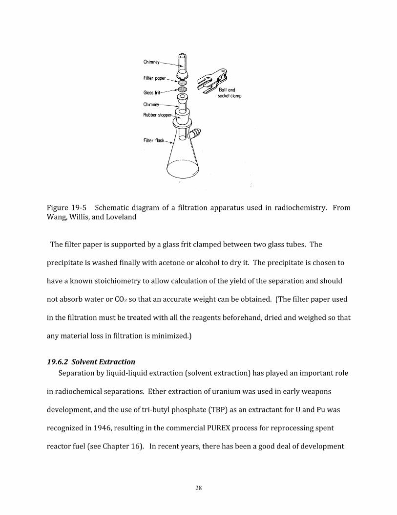
collected by filtration (Figure 19-‐5).
28
Figure 19-‐5 Schematic diagram of a filtration apparatus used in radiochemistry. From Wang, Willis, and Loveland The filter paper is supported by a glass frit clamped between two glass tubes. The
precipitate is washed finally with acetone or alcohol to dry it. The precipitate is chosen to
have a known stoichiometry to allow calculation of the yield of the separation and should
not absorb water or CO2 so that an accurate weight can be obtained. (The filter paper used
in the filtration must be treated with all the reagents beforehand, dried and weighed so that
any material loss in filtration is minimized.)
19.6.2 Solvent Extraction Separation by liquid-‐liquid extraction (solvent extraction) has played an important role
in radiochemical separations. Ether extraction of uranium was used in early weapons
development, and the use of tri-‐butyl phosphate (TBP) as an extractant for U and Pu was
recognized in 1946, resulting in the commercial PUREX process for reprocessing spent
reactor fuel (see Chapter 16). In recent years, there has been a good deal of development

29
of solvent extraction processes for the removal of the transuranic elements, 90Sr, and 137Cs
from acidic high level waste. Laboratory demonstrations of the TRUEX process that uses
the neutral extractant CMPO (octyl(phenyl)-‐N,N-‐diisobutylcarbamoyl-‐methylphosphine
oxide) to separate the transuranium elements from acidic high-‐level waste have been
successful. More recently crown ethers have been used as specific extractants for Sr and
Cs.
In solvent extraction, the species to be separated is transfered between two immiscible
or partially miscible phases, such as water and a nonpolar organic phase. To achieve
sufficient solubility in the organic phase, the species must be in the form of a neutral, non-‐
hydrated species. The transfer between phases is achieved by selectively complexing the
species of interest causing its solubility in water to decrease with a concomitant increase
in its solubility in the organic phase.
A hydrated metal ion (MZ+) will always prefer the aqueous phase to the organic phase.
To get the metal ion to extract, some or all of the inner hydration sphere must be removed.
The resulting complex must be electrically neutral and organophilic, that is, have an
organic "surface" that interacts with the organic solvent. This can be done by:
a. forming a neutral complex MAZ by coordination with organic anions A-‐
b. replacing water in the inner coordination sphere by large organic molecules B such
that one forms
!
MBNZ + which is extracted into the organic phase as an ion-‐association
complex
c. forming metal complexes of form
!
MLNZ"N with ligands (L) such that they combine with
large organic cations RB+ to form ion pair complexes
!
(RB+)N"Z (MLN )N"Z

30
The extracting agents are thus divided into three classes, polydentate organic anions
A-‐, neutral organic molecules B or large organic cations RB+.
Polydentate organic anions, which form chelates (ring structures of 4-‐7 atoms) are
important extracting agents. Among these are the β-‐diketonates, such as acetylacetonate,
the pyrazolones, benzoylacetonate, and thenoyltrifluoroacetone (TTA), with the
extraction increasing strongly through this sequence. Representing the organic chelating
agent as HA, the overall reaction involved in the chelate extraction of a metal ion, Mn+, is
Mn+(aq) + nHA(o) ↔MAn(o) + nH+(aq)
When an aqueous solution containing extractable metal ions is brought into contact with
an organic phase containing chelating agent, the chelating agent dissolves in the water
phase, ionizes, complexes the metal ion, and the metal chelate dissolves in the organic
phase. The low solubility of the metal complexes and their slow rates of formation limit
the industrial use of this type of anionic extraction.
However, a number of organophosphorus compounds are efficient extractants as they
and their complexes are very soluble in organic solvents. The most important of these are
monobasic diethylhexylphosphoric acid (HDEHP) and dibutylphosphoric acid (HDBP).
The actinide
!
MO22+ ions are very effectively extracted by these reagents as are the
actinide (IV) ions.
Among the neutral extractants, alcohols, ethers, and ketones have been used
extensively. The most famous example of these is the extraction of uranyl nitrate into
diethyl ether, the process used in the Manhattan Project to purify the uranium used in the
first reactors. In one of the early large scale processes (the Redox process) to recover

31
uranium and plutonium from irradiated fuel, methyl isobutyl ketone was used to extract
the actinides as nitrates.
The most widely used neutral extractants, however, are the organophosphorus
compounds, of which the ester, tributylphosphate (TBP), is the most important. TBP
forms complexes with the actinide elements thorium, uranium, neptunium, and
plutonium by bonding to the central metal atom via the phosphoryl oxygen in the
structure
(C4H9O)3P+⎯O-‐
The overall reactions are
!
MO22+(aq) + 2NO3
"(aq) + 2TBP(o)#MO2(NO3)2 •2TBP(o)
or
!
M 4+(aq) + 4NO3"(aq) + 2TBP(o)#M(NO3)4 (TBP)2(o)
These equilibria can be shifted to the right, increasing the degree of extraction by
increasing the concentration of uncombined TBP in the organic phase or by increasing the
concentration of [
!
NO3"(aq)]. The latter increase is achieved by adding a salting agent such
as HNO3 or Al(NO3)3. These extraction equilibria are the basis of the PUREX process, used
almost exclusively in all modern reprocessing of spent nuclear fuel.
A third group of extractants (the cationic extractants) are the amines, especially
the tertiary or quarternary amines. These strong bases form complexes with actinide
metal cations. The efficiency of the extraction is improved when the alkyl groups have
long carbon chains, such as trioctylamine or triisooctylamine. The extraction is
conventionally thought of as a "liquid anion exchange" in that the reaction for metal
extraction can be written as an anion exchange, that is,

32
!
xRB+L"(o) + MLn"x # (RB+)x MLn
x (o) + xL"
where
!
MLn"x is the metal anion complex being extracted and RB+ is the ammonium salt of
the amine. Hexavalent and tetravalent actinides are efficiently extracted using this
technique while trivalent actinides are not well extracted under ordinary conditions.
As a practical matter, the distribution ratio D is defined as
D = [M]org/[M]aq
where [M]i is the metal ion concentration in the ith phase. The relevant equilibria, for
example, to describe the extraction in systems of lipophilic acidic chelating agents are
HLorg HLaq
HLaq H+ + Laq-‐
Maq3+ + 3HLorg (ML3)org + 3H+aq
where Ke is the equilibrium constant for the last reaction. The distribution coefficient D is
given as
D=[ML3]org/[M3+]aq = Ke [HL]3org / [H+]3aq
If one introduces a water soluble complexing agent into the system, the [M3+]aq becomes
[M3+] + [MX2+] + [MX2+] + … and the measured distribution ratio will include these species
as well. The separation factor between two ions, S, is given by the ratio of their distribution
coefficients
S=DA/DB

33
Thus, the most effective separations will involve cases where the target ion interacts
strongly with the extractant but is less strongly complexed by the aqueous ligand X. The
percent extraction is given by
!
%extraction =100D
D+Vaq
Vorg
"
# $ $
%
& ' '
where Vi is the volume of the ith phase.
19.6.3 Ion Exchange Ion exchange is one of the most popular radiochemical separation techniques due to
its high selectivity and the ability to perform separations rapidly. In ion exchange, a
solution containing the ions to be separated is brought into contact with a synthetic organic
resin containing specific functional groups that selectively bind the ions in question. In a
later step the ions of interest can be removed from the resin by elution with another
suitable solution that differs from the initial solution. Typically the solution containing the
ions is run through a column packed with resin beads. The resins are typically cross-‐linked
polystyrenes with attached functional groups. Most cation exchangers (such as Dowex 50)
contain free sulfonic acid groups, SO3H, where the cation displaces the hydrogen ion. Anion
exchangers (such as Dowex 1) contain quaternary amine groups, such as CH2N(CH3)3Cl
where the anion replaces the chloride ion. The resin particles have diameters of 0.08 – 0.16
mm and exchange capacities of 3-‐5 meq per gram of dry resin.
It is common to absorb a group of ions on the column material and then selectively
elute them. Complexing agents, which form complexes of varying solubility with the
absorbed ions, are used as eluants. A competition between the complexing agent and the
resin for each ion occurs and each ion will be exchanged between the resin and the

34
complexing agent several times as it moves down the column. This is akin to a distillation
process. The rates at which the different ions move down the column vary, causing a
spatial separation between “bands” of different ions. The ions can be collected separately
in successive eluant fractions (see Figure 19-‐6).
Figure 19-‐6. Elution of tripositive lanthanide and actinide ions on Dowex-‐50.
The most widely cited application of ion exchange techniques is the separation of
the rare earths or actinides from one another. This is done with cation exchange using a
complexing agent of α-‐hydroxyisobutyric acid (“α-‐but”). The order of elution of the ions
from a cation exchange column is generally in order of the radii of the hydrated ions with
the largest hydrated ions leaving first; thus lawrencium elutes first and americium last
among the tri-‐positive actinide ions (see Figure 19-‐6). In the case of the data of Figure 19-‐
6, the separation between adjacent cations and the order of elution is derived from the

35
comparative stability of the aqueous actinide or lanthanide complexes with α-‐
hydroxyisobutyrate. As shown in Figure 19-‐6, there is a strikingly analogous behavior in
the elution of the actinides and lanthanides that allowed chemists to prove the identity of
new elements in the discovery of elements 97-‐102 (Bk-‐No). For cation exchange, the
strength of absorption goes as M4+ > M3+ > MO22+ > M2+ > MO2+.
The anion exchange behavior of various elements has been extensively studied. For
example, consider the system of Dowex 1 resin and an HCl eluant. Typical distribution
ratios for various elements as a function of [Cl-‐] are shown in Figure 19-‐7. Note that groups
i,2, and 3 are not absorbed on the column. One usually sees a rise in the distribution
coefficient D until a maximum is reached and then D decreases gradually with further
increases in [Cl-‐]. The maximum occurs when the number of ligands bonding to the metal
atom equals the initial charge on the ion. The decrease in D with further increases in eluant
concentration is due to free anions from the eluant competing with the metal complexes for
ion-‐exchange resin sites. Figure 19-‐7 or similar data can be used to plan separations. For
example, to separate Ni(II) and Co (II), one needs simply to pass a 12 M HCl solution of the
elements through a Dowex 1 column. The Co (II) sticks to the column while the Ni (II) is
not absorbed. A mixture of Mn (II), Co (II), Cu (II), Fe (III), and Zn (II) can be separated by
being placed on a Dowex 1 column using 12 M HCl, followed by elutions with 6M HCl (Mn),
4 M HCl (Co), 2.5 M HCl (Cu), 0.5 M HCl (Fe) and 0.005 M HCl (Zn).

36
Figure 19-‐7. Elution of elements from anion exchange resin. (12).
In addition to the organic ion exchange resins, some inorganic ion exchanges, such
as the zeolites, have been used. Inorganic ion exchangers are used in situations where heat
and radiation might preclude the use of organic resins although the establishment of
equlibria may be slow.
Newer developments have emphasized the preparation of more selective resins.
Among these are the chelating resins (such as Chelex-‐100) that contain functional groups
that chelate metal ions. Typical functional groups include iminodiacetic acids, 8-‐
hydroxyquinoline or macrocyclic units such as the crown ethers, calixarenes or cryptands.
The bifunctional chelating ion exchange material, Diphonix® resin—a substituted
diphosphonic acid resin, shows promise in treating radioactive waste. Important newer
resins include those with immobilized phosphorus ligands. [11]

37
19.6.4 Exchange Chromatography
Extraction chromatography is an analytical separation technique that is closely
related to solvent extraction. Extraction chromatography is a form of solvent extraction
where one of the liquid phases is made stationary by adsorption on a solid support. The
other liquid phase is mobile. Either the aqueous or the organic phase can be made
stationary. Extraction chromatography has the selectivity of solvent extraction and the
multistage character of a chromatographic process. It is generally used for laboratory scale
experiments although some attempts have been made to use it in larger scale operations.
The common applications involve the adsorption of an organic extractant onto a variety of
inorganic substrates such as silica or alumina or organic substrates such as cellulose or
styrene-‐divinyl benzene copolymers. When the stationary phase is organic, the technique is
referred to as reversed-‐phase high-‐performance liquid chromatography. The stationary
phase is used in a column just as in ion-‐exchange chromatography. High pressure pumps
are usually used to force the liquid phase through these columns, just as in conventional
high-‐performance liquid chromatography.
The same extracting agents as used in solvent extraction can be used in extraction
chromatography. Early applications of extraction chromatography have employed various
traditional extractants such as the acidic organophosphorus compounds (di-‐ (2-‐ethylhexyl)
phosphoric acid, HDEHP) or TBP as extractants for the actinide elements. Recent advances
have led to a variety of new solvent exchange extractants such as the crown ethers,
cryptands or bifunctional organophosphorus compounds. A particularly successful
application is the selective sorption of actinides on TRU resins, involving solutions of
carbamolymethyl-‐phosphoryl (CMPO) compounds in TBP sorbed on Amberlite XAD-‐7.

38
This resin has found a number of applications in the isolation and subsequent
determination of the actinides in complex matrices.
19.6.5 Rapid Radiochemical Separations Many of the separation techniques we have described take hours to perform. Many
interesting nuclei, such as the heavier actinides, the transactinides, or the light nuclei used
in PET studies have much shorter half-‐lives. Thus, we will briefly review the principles of
rapid radiochemical separations (procedures that take seconds to minutes) and refer the
reader to (13-‐16) for details.
In most chemical separation procedures, the goal is to selectively transfer the species of
interest from one phase to another, leaving behind any unwanted species. The phase-‐to-‐
phase transfer is rapid, but the procedures to place the species in the proper form for
transfer to occur are slow. The goal of rapid radiochemical separations is to speed up
existing chemical procedures or to use new, very fast chemical transformations.
Two procedures are commonly used for rapid radiochemical separations, the batch
approach and the continuous approach. In the batch approach, the desired activities are
produced in a short irradiation, separated and counted with the procedure being repeated
many times to reduce the statistical uncertainty in the data. In the continuous approach,
the production of the active species is carried out continuously and the species is isolated
and counted as produced.
One of the most widely used techniques for rapid chemical separation is that of gas
chromatography, which has been developed for use with the transuranium elements by
Zvara and co-‐workers (17). In gas chromatography, volatile elements or compounds are
separated from one another by their differences in distribution between a mobile gas phase

39
and a stationary solid phase. Thermochromatography involves passing a gas through a
column whose temperature decreases continuously with distance from the entrance. Thus
the less volatile species condense on the column walls first with the more volatile species
depositing last. Measurement of the migration times, the deposition temperature, the
temperature gradient in the column, etc can allow one to deduce the molar enthalpy of
absorption of the compound on the column material. This physical quantity can be
compared to quantum chemical calculations of this quantity to gain insight into the
bonding properties of the element in question. This technique was used to show the
chemical properties (18-‐20) of the transactinides Rf-‐Hs and their behavior relative to their
chemical congeners.
Another rapid chemical separation technique is separation by volatilization. There
are a variety of volatile compounds that can be released from an irradiated material upon
dissolution that can, with proper conditions, serve to rapidly chemically separate the
elements involved. Examples of such volatile species include I2, At GeCl4, AsCl3, SeCl4, OsO4,
RuO4, Re2O7, Tc2O7, etc. Separation by volatilization has largely been used for the elements
forming volatile hydrides, As, Se, Sn, Sb and Te.
19.7.1 Low level measurement techniques 19.7.2 Introduction One of the areas in which the skills of radiochemists are used is the area of
low-‐level chemistry and low level counting. Areas as diverse as the detection of solar
neutrinos or the study of environmental radioactivity involve low level techniques. For
example, despite concentration of the radiotracers of interest during sampling procedures
in environmental studies, quite often one is left with a sample containing a small quantity <

40
10 ppm of radioactivity that must be assayed. Such essays are referred to as low level
techniques. Let us begin our discussion of low level techniques by considering any
chemical manipulations of the sample that must be made prior to counting it.
Understandably the fact of having activity levels < 10 dpm, puts severe restrictions on the
nature of low level chemistry. Among the requirements for low level chemistry are a small
constant blank, high chemical yields for all procedures, high radiochemical purity for all
reagents employed, and the ability to place the sample in suitable chemical form for
counting.
19.7.3 Blanks
The blank in low-‐level chemistry is defined as the contribution of the added
reagents and other sample constituents to the activity being measured. The blank is
determined by performing the chemical procedures without the radioactive sample being
analyzed. Care must be taken to ensure that the blank is properly measured and includes
all possible contributions to the activity that would be encountered in a real system. For
example, in the determination of fission product 144Ce in seawater, the blank must be
determined for each new bottle of reagents used due to the high variability of the 144Ce
content in chemical reagents.
Clearly one of the most effective ways of dealing with a blank correction is to
reduce it to its lowest level. Among the factors contributing to the blank correction that
can be reduced with care is radiochemical contamination of analytical reagents used in
chemical procedures. DeVoe and Sugihara have written extensive review articles [21,22]
on this subject and their work should be consulted for detailed information. Typical
contamination of most reagents is in the range of ~ 10 to 100 ppm/g reagent, although
41
individual reagents may contain activity levels of > 10,000 ppm /gram. Some especially
troublesome reagents are rare earths (Ce salts in particular), chlorine or sulfur-‐ containing
reagents which may contain 32P contamination, cesium salts (which may contain 40K or
87Rb) and potassium salts and other obvious offenders. Precipitating agents, such as
tetraphenylborates and chloroplatinates are also particularly pernicious with regards to
contamination problems.
Airborne contamination is another possible contribution to the black
correction. Here one is chiefly concerned with sample contamination with the daughters of
222Rn, which have half lives in the 30 to 40 minute range. Steps that can be taken to avoid
this problem include eschewing the use of suction filtration in chemical procedures,
prefiltering of room air and use of radon traps.
Further lowering of the blank correction occurs when non-‐isotopic carriers
in chemical procedures are used to replace inert carriers of the element of interest when it
is difficult to obtain the inert carrier in a contamination free condition. Obviously only
clean glassware should be used, reagents should not be reused, and the laboratory should
be kept in an immaculate condition. Separations that have high chemical yields and high
radiochemical purity reduce the blanks.
19.7.3 Low level counting-‐-‐general principles
Once the low level radioactive sample has been collected and any chemical
procedures performed prior to counting, it is ready for counting. Because of the extremely
small disintegration rates encountered, special techniques, called low level counting, must
be used to assay the sample. We shall survey some of the highlights of this area which is

42
been the subject of many articles and monographs. [7]
What are the most important characteristics the detector must possess for
low-‐level counting? The first general characteristic is one of stability. Low level counting
frequently requires counting periods of long duration; hence counter stability is quite
important. If the sample count rate S (source + background) is only slightly larger than the
background rate B, one’s detector should be picked to maximize the ratio S2/B-‐-‐ that is, low
background and high efficiency. If the sample count rate is large with respect to
background, one need only maximize
S-‐-‐ that is, one chooses a high efficiency detector.
19.7.4-‐-‐Low level counting-‐-‐ details
For low level α-‐particle counting, the choice is generally between the gas
filled ionization chamber and a semiconductor detector system. The former can have a
counting efficiency of approximately 50% and a background of approximately three to four
cpm; the latter has a background rate of approximately 0.5 cph and a detection efficiency
that approaches 50%. The semiconductor detector is usually the detector of choice
although large sample sizes may be better assayed with gas filled ionization chambers.
Background radiation is primarily due to α-‐particle emitting impurities in the counter,
counter support material and so on, plus the occurrence of cosmic ray induced (n,α)
reactions. Because of its Ra content, Al is not used in constructing α-‐spectrometers.
Low-‐level “soft” radiation counting has its own techniques. The term “soft
radiation counting” refers to detecting EC and low energy β-‐ emitters where the self-‐
absorption of the radiation in the sample is important. To solve this problem, one typically
tries to incorporate the radionuclide to be counted into the detector itself. One typical
43
method of assay is liquid scintillation counting, which is used to assay samples whose
activity is greater than 10 pCi. Typical liquid scintillation counter backgrounds can be high
as high as approximately 100 counts per minute whereas special counters have been built
with a background rates of approximately 10 CPM or less. Liquid scintillation counting is a
speedy, simple method of low level counting. Another technique that has been used to
count low-‐level soft radiation samples involves the use of gas filled proportional counter.
The sample to be counted is converted to gaseous form and added to the counter gas at a
concentration of approximately 0.05 mole percent or less. This method of low-‐level
counting, although tedious and time-‐consuming, allows one to assay samples whose
activity is less than 0.5 picocuries. Typical counter backgrounds are ~1 to 2 cpm with
100% counting efficiency for energies as low as ~10 eV.
The counting of tritium in water is a special problem about which much has
been written. Current methods for assay of tritium in water have a range of 0.1 to 5000 TU
where a tritium unit (TU) has the value of 7.2 dpm/L. The most desirable feature of a
tritium measuring system is that it be capable measuring a large number of samples is
rapidly, simply and cheaply as possible with an uncertainty of ~ ±10% or better. It is
generally more important to assay 100 samples with an uncertainty of ±10% than to assay
10 samples with an uncertainty of ± 3%.
The basic feature of low-‐level β-‐ counting that distinguishes it from ordinary
β-‐ counting is the use of an anticoincidence shield around the main β-‐ counters. An
anticoincidence shield is a single detector, or array of detectors that surrounds the primary
detector. The output of the anticoincidence detector is fed to an anticoincidence circuit
along with the output of the primary detector. When nuclear radiation passes through

44
both detectors simultaneously, as in the case of a highly penetrating cosmic ray striking
both detectors, no output results from the anti-‐coincidence circuit. When the
anticoincidence circuit receives a signal only from the primary detector, an output signal
results. The net effect is that the anticoincidence shield detector “guards” or shields
against exterior radiation background radiation entering the primary detector. Typical
ring assemblies reduce the background rate in the primary counter by a factor of ~50. A
well-‐designed guard ring will allow several different types of central counter to be inserted
into it. Low background β-‐ counters constructed of especially pure materials with
anticoincidence shields have exhibited background rates of ~ 1 cph with efficiencies of
approximately 50%.
Low level counting of γ-‐ray emitters using solid scintillation counters is an
extensively used technique. For detailed discussions of this technique, the reader is
referred to the excellent review articles. The most important aspect of low-‐level solid
scintillation counting is to decrease the counter background. Typical contributions to a
solid scintillation counter’s background rate from various sources are shown in Table 19-‐3.
Table 19-‐3 Components of a NI(Tl) Scintillation Counter Background
(A. Stenberg and I.U. Olsson. Nucl. Instr, Meth. 61, 125 (1968).
Outside Shield 29.200 cpm

45
Inside Shield
Cosmic Ray Mesons 116.4 cpm
Cosmic Ray Neutrons 19.4 cpm
222Rn Daughters 25.9 cpm
40K 8.6 cpm
Remaining Background 33.1 cpm
Total 203.4 cpm
Here four factors are seen as the major contributors to the detector background rate. They
are (a) the cosmic ray shield (b) the atmosphere surrounding the detector (c) the detector
itself and (d) the cosmic rays. For the cosmic ray shield about the detector, it is advisable
to use old or virgin lead. i.e., lead that was purified over 100 years ago, thus allowing any
210Pb present to decay. One should expect ~1 cpm/g shield material. Iron can also be
used in constructing the detector shield, but care must be taken to ensure that the iron or
steel is pre 1945 in origin. (Iron processed in the post-‐1945 period has 60Co
contamination due to the use of 60Co in the blast furnace operation.) Mercury is a very
good, easily purified shield material but is quite expensive. “Graded” shields consisting of
an outer thick layer of Pb lined with Cd which in turn is coated with Cu are used to reduce
the production of x-‐rays in the Pb shield material. The main portion of the atmospheric
contribution to the detector background is due to radon and its daughters. Particularly
troublesome in this regard is the fact that atmospheric radon concentrations can fluctuate
by a factor of 40 during the course of a day. Once again the problem is best handled by
filtering the room air, rapid air turnover and the use of inert atmospheres (N2 from

46
evaporation of liquid nitrogen) inside counting assemblies. A NaI detector will contain
some 40K impurity, which will contribute to the background. The detector housing is also a
potential contributor to the background. Copper appears to be the best material for
detector housing with aluminum being the least preferred, for it can be expected to contain
~ 10-‐13 Ci Ra/g Al. In reducing the cosmic ray component of the background one tries to
stop the “soft” cosmic rays (electrons, X and γ-‐rays) in the detector shield while using an
anti coincidence system to stop the “hard’ component of the cosmic radiation (mesons, etc.)
At first one might think that germanium detectors with their low detection
efficiencies would have little use in low level counting. However such is not the case
because of the complexity of a radionuclide mixture found in environmental samples, the
virtual impossibility of drawing significant conclusions from NaI detector spectra due to
poor energy resolution. Clearly there are many cases in which the very good energy
resolution of the germanium detector is a necessity. Furthermore, recent developments in
detector fabrication techniques allow the production of germanium detectors with detector
efficiencies equal to that of standard (3” x 3”) NaI detectors.
A number of special techniques have evolved to increase the detection
sensitivity in γ-‐ray counting. One of the most important is the suppression of the Compton
scattering events in the γ-‐ray spectrum by the use of anticoincidence annulus around the
central γ-‐ray detector. The idea behind a Compton suppression spectrometer is that most
events in which the incident photon undergoes one or more Compton scattering events in
the central detector will result in partial energy deposition in the detector with a low
energy photon escaping the detector. Suppression is accomplished by setting up an
anticoincidence between the central detector signal and any signal coming from the
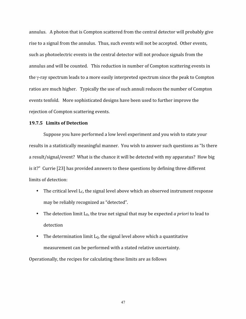
47
annulus. A photon that is Compton scattered from the central detector will probably give
rise to a signal from the annulus. Thus, such events will not be accepted. Other events,
such as photoelectric events in the central detector will not produce signals from the
annulus and will be counted. This reduction in number of Compton scattering events in
the γ-‐ray spectrum leads to a more easily interpreted spectrum since the peak to Compton
ratios are much higher. Typically the use of such annuli reduces the number of Compton
events tenfold. More sophisticated designs have been used to further improve the
rejection of Compton scattering events.
19.7.5 Limits of Detection
Suppose you have performed a low level experiment and you wish to state your
results in a statistically meaningful manner. You wish to answer such questions as “Is there
a result/signal/event? What is the chance it will be detected with my apparatus? How big
is it?” Currie [23] has provided answers to these questions by defining three different
limits of detection:
• The critical level LC, the signal level above which an observed instrument response
may be reliably recognized as “detected”.
• The detection limit LD, the true net signal that may be expected a priori to lead to
detection
• The determination limit LQ, the signal level above which a quantitative
measurement can be performed with a stated relative uncertainty.
Operationally, the recipes for calculating these limits are as follows
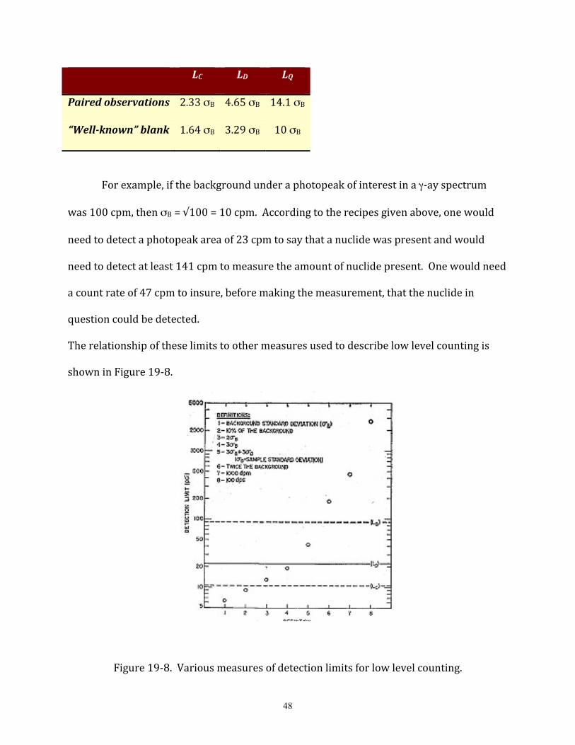
48
LC LD LQ
Paired observations 2.33 σB 4.65 σB 14.1 σB
“Well-‐known” blank 1.64 σB 3.29 σB 10 σB
For example, if the background under a photopeak of interest in a γ-‐ay spectrum
was 100 cpm, then σB = √100 = 10 cpm. According to the recipes given above, one would
need to detect a photopeak area of 23 cpm to say that a nuclide was present and would
need to detect at least 141 cpm to measure the amount of nuclide present. One would need
a count rate of 47 cpm to insure, before making the measurement, that the nuclide in
question could be detected.
The relationship of these limits to other measures used to describe low level counting is
shown in Figure 19-‐8.
Figure 19-‐8. Various measures of detection limits for low level counting.
49
*
References
1. The Random House College Dictionary, Revised Edition (Random House, New York,
1984).
2. J.P. Adloff and R. Guillamont, Fundamentals of Radiochemistry (CRC Press, Boca
Raton, 1984).
3. K. Lieser, Nuclear and Radiochemistry: Fundamentals and Applications (VCH, New
York, 1997).
4. W. D. Ehmann and D.E. Vance, Radiochemistry and Nuclear Methods of Analysis
(Wiley, New York, 1991).
5. R.J. Woods, J.W.T. Spinks, B. Spinks, An Introduction to Radiation Chemistry, (Wiley,
New York, 1990); A. Mozumder, Fundamentals of Radiation Chemistry(Academic,
New York, 1999)
6. W. C. Parker and H. Slatis, “Sample and Window Techniques”, in Alpha-‐, Beta-‐ And
Gamma-‐Ray Spectroscopy, Vol 1, K. Siegbahn, ed. (North_Holland, Amsterdam, 1966),
pp 379-‐408.
7. G.F. Knoll, Radiation Detection and Measurement, 3rdEdition (Wiley.New York, 2000)
8. N. Tsoulfanidis, Measurement and Detection of Radiation,2ndEdition (Taylor and
Francis, Washington, 1995).
9. B.G. Harvey, “Recoil Techniques in Nuclear Reactions and Fission Studies” in Ann.
Rev. Nucl. Sci. 10, 235 (1960).
50
10. A. Ghiorso, et al., Nucl. Instru. Meth. A269, 192 (1988); Y.T. Oganessian, et al., Phys.
Rev. C 64, 064309 (2001).
11. Metal Ion Separations and Preconcentration; Bond, A.H.;Dietz, M.L.;Rogers, R.D., Eds.;
ACS Symposium Series 716;ACS, Washington, DC, 1999.
12. K. Kraus, and D. Nelson, Paper 837, Geneva Conference, Vol. 7. (1956).
13. G. Herrman, and N. Trautman, Annu. Rev. Nucl. Part. Sci. 1982, 32, 117.
14. R.A. Meyer, and E.A. Henry, Proc. Workshop Nucl. Spectrosc. Fission Products,
Grenoble1979; Bristol, London, 1979; pp 59-‐103.
15. M. Schädel, et al., Nucl. Instr. Meth. Phys. Res. A264, 308 (1988).
16. N. Trautmann, Radiochimica Acta 70/71, 237 (1995).
17. I. Zvara, et al. Sov. Radiochemistry1972, 14, 115
18. M. Schädel, et al. Nature 1997, 388, 55.
19. R. Eichler, et al. Nature 2000, 407, 63.
20. Ch. E. Düllmann, et al. GSI Scientific Report 2001; GSI, Darmstadt, 2002; p. 179.
21. J.R. DeVoe, “Radioactive contamination of materials used in scientific research”,
NAS-‐NRC 895 (1961).
22. T.T. Sugihara, “Low Level Radiochemical Separations”, NAS-‐NRC 3103.
23. L.A. Currie, Anal. Chem. 40, 586 (1968).

51
General References
1. J.P. Adloff and R. Guillamont, Fundamentals of Radiochemistry (CRC Press, Boca
Raton, 1984).
2. C.H. Wang, D.L. Willis, and W. Loveland, Radiotracer Methods in the Biological,
Physical and Environmental Sciences (Prentice-‐Hall, Englewood Cliffs, 1975).
3. K. Lieser, Nuclear and Radiochemistry: Fundamentals and Applications (VCH, New
York, 1997).
4. G.R. Choppin, Experimental Nuclear Chemistry, (Prentice-‐Hall, Englewood Cliffs,
1961)
5. M. LeFort, Nuclear Chemistry, (Van Nostrand, Princeton, 1968).
6. G. Friedlander, J.W. Kennedy, J.M. Miller and E.S. Macias, Nuclear and
Radiochemistry, (Wiley, New York, 1981).
7. G.T. Seaborg and W. Loveland, The Elements Beyond Uranium,(Wiley, New York,
1990).
8. D. Brune, B. Forkman, and G. Persson, Nuclear Analytical Chemistry, (Chartwell-‐
Brandt, Lund, 1984).
9. W. D. Ehmann and D.E. Vance, Radiochemistry and Nuclear Methods of Analysis
(Wiley, New York, 1991).
10. G. Choppin, J.-‐O. Liljenzin, and J. Rydberg, Radiochemistry and Nuclear Chemistry,
3rd Edition, (Butterworth-‐Heinemann, Woburn, 2002).

52
11. W. C. Parker and H. Slatis, “Sample and Window Techniques”, in Alpha-‐, Beta-‐
And Gamma-‐Ray Spectroscopy, Vol 1, K. Siegbahn, ed. (North_Holland,
Amsterdam, 1966), pp 379-‐408.

53
Problems
1. A beam of 1 particle-‐µampere of 48Ca10+ ions is incident on an Al foil that is 5
mg/cm2 thick. (a) Estimate the energy deposit/sec in the foil. (b) If the foil has an
area of 4 cm2 and it is mounted in a vacuum with no cooling, how long will it take
until the foil reaches the melting point of Al (660° C)? Assume the specific heat of Al
is independent of temperature and is 0.25 cal/°/g.
2. Au foils are to be used as flux monitors in a nuclear reactor. What is the maximum
thickness that can be used if the self-‐shielding corrections are to be less than 10%?
3. The reaction 27Al(p,3pn)24Na is to be used to measure the proton flux in an
irradiation with 300 GeV protons. The cross section for this reaction is known to be
10.1 mb. The flux monitor is 5.0 mg/cm2. One measures a 24Na counting rate
(background corrected) of 10,000 cpm (in a 2% efficient detector) 24 hours after a
0.5 hour irradiation. What was the average proton flux during the irradiation?
4. Imagine you have for your use a nuclear reactor with a flux of 1013 n/cm2/s in its
irradiation facility and a cyclotron with a beam of 10.5 MeV protons, 21 MeV
deuterons and 42 MeV α-‐particles. What would be the best way to prepare: (a)
140Ba (b) carrier-‐free 99Tcm (c) carrier-‐free 144Ce (d) 237Np (e) 254Es (f) carrier
free 18F for incorporation into glucose. Outline the target and reaction to be used,
how the target would be prepared and any chemical separations to be done
following irradiation.

54
5. What value of Bρ would you use in a gas-‐filled separator if you wanted to separate
254No produced in the reaction of 215 MeV 48Ca with 208Pb. You may assume qave for
254No is 1 torr He gas is 17+.
6. As a radiochemist, you have been asked to prepare the following accelerator targets
for your research group. They are: (a) 226Ra (b) 208Pb (c) 238U (d) 244Pu (e) 90Zr
(f) 124Sn. Assume all targets are to be 0.5 mg/cm2. For each target, outline the best
method of target preparation, the backing foil used, if any and the reasons for your
choice. Describe any anticipated problems in each procedure.
Top Related