


Languages
Pages
Legal


3
Catalogue
ImperialIssue A (09/19)
4
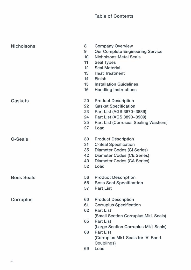
Company OverviewOur Complete Engineering ServiceNicholsons Metal SealsSeal TypesSeal MaterialHeat TreatmentFinishInstallation GuidelinesHandling Instructions
Nicholsons
Table of Contents
8910111213141516
Product DescriptionGasket SpecificationPart List (AGS 3870–3889)Part List (AGS 3890–3909)Part List (Corruseal Sealing Washers)Load
Gaskets 202223242527
Product DescriptionC-Seal SpecificationDiameter Codes (CI Series)Diameter Codes (CE Series)Diameter Codes (CA Series)Load
C-Seals 303135424952
Product DescriptionBoss Seal SpecificationPart List
Boss Seals 565657
Product DescriptionCorruplus SpecificationPart List (Small Section Corruplus Mk1 Seals)Part List (Large Section Corruplus Mk1 Seals)Part List (Corruplus Mk1 Seals for ‘V’ Band Couplings)Load
Corruplus 606162
65
68
69

5
Product DescriptionE-Seal SpecificationDiameter Codes (EIS Series)Diameter Codes (EES Series)Diameter Codes (EIL Series)Diameter Codes (EEL Series)Load
E-Seals 72 737680848894
Product DescriptionHigh Temperature Duct Seal SpecificationPart List (S2283–XXX Series)Part List (S2283–XXX-SP Series)Part List (S2314–XXX Series)Part List (S2346–XXX Series)Part List (S2347–XXX Series)Cross Reference Table
High Temperature Duct Seals 9899100101102103104105
Product DescriptionSigma Seal SpecificationStandard Sigma Seal SectionsLoad
Sigma Seals 110111112114
Product DescriptionMulti Bellow Seal Specification
GlossaryAcknowledgements
Multi Bellow Seals 118119
120121

6

7
Company OverviewOur Complete Engineering ServiceNicholsons Metal SealsSeal TypesSeal MaterialHeat TreatmentFinishInstallation GuidelinesHandling Instructions
Nicholsons
8910111213141516

8
Nicholsons Group is a global specialist in the design and manufacture of resilient metal seals and gaskets. Our extensive range of precision metal seals offers sealing solutions for extreme temperature, pressure and compression applications.
Established in 1923, Nicholsons has design, sales and manufacturing sites in Europe and USA. We have the experience and global presence to support you with your sealing requirements.
Our seals are used in a number of sectors including:
– Aerospace (Civil and Military)– Automotive – Oil and Gas– Power Generation– Nuclear– Medical
Our metal seals are capable of sealing a wide range of media from helium gas to heavy oil, operating in extreme environments from cryogenic to high temperatures, and vacuum to high pressures.
Company Overview

9 Nic
ho
lso
ns
Nicholsons deliver a complete engineering service from design and prototype manufacture to full volume production of standard, optimised and fully bespoke seals.
Our team of Engineers have significant experience in designing the optimum seal for a wide range of customer applications and use a variety of methods during the development process of a design. Our design engineering capabilities include:
– Non-Linear Finite Element Analysis (FEA)– Stress, fatigue and buckling analysis– Modelling of loads, pressure effects, modification of part geometry and
cavity relaxation– Qualification testing specific to customer requirements– Physical testing and measurement including load vs deflection, pressure testing
and fatigue testing
For more specific testing requirements, we work with third party consultants, Universities and test facilities.
Our Production Engineering Departments develop and manufacture rolling, press and forming tools, as well as the specialist machines required during the manufacturing process. Production Engineers identify the most controlled and cost-effective method of manufacture for each new part and continually focus on the development and improvement of precision forming and rolling methods to ensure that manufacturing methods continue to progress.
Our in-house production capabilities include welding, rolling, forming, laser-cutting, machining, heat treatment and chemical processing. Quality is key when designing and manufacturing parts for safety critical and extreme environments. Nicholsons hold ISO, AS and TS accreditations and are Nadcap approved for various special processes.
Nicholsons Engineering and Sales teams work closely with our customers to ensure projects are managed in line with, and exceed, customer expectations. We recommend that you involve us as early as possible in your design process to ensure that the most appropriate sealing solution is specified in terms of performance, cost and lead time.
Our Complete Engineering Service

10
Nicholsons Metal Seals
Customer requirements are becoming more demanding in terms of increased temperatures, leakage legislation, length of product life and the need for greater efficiencies. Our metal seals are able to cope with and support these demands.
Benefits of Metal Seals:
– Available in a wide range of sections, materials, heat treatments and finishes– Able to cope with large thermal movement of hardware– Can be adapted to suit multiple hardware arrangements– No issues related to explosive decompression– Long shelf life
Our core product range includes the following seal types:
– Corruseal Gasket– C-Seal– Boss Seal– Corruplus– E-Seal– High Temperature Duct Seal– Sigma Seal– Multi Bellow Seal (W-Seal/M-Seal)
The product groups fall into one of three main categories:
– Standard Parts: Corruseal Gasket, Boss Seal, Corruplus, High Temperature Duct Seal
– Part numbers that can be built to a variety of specifications: C-Seal, E-Seal– Seal sections that require design input: Sigma Seal, Multi Bellow Seal
This catalogue includes Nicholsons core product groups, however, it does not cover the full range of sealing options that we have available. Each product type can be adapted to meet non-standard applications and product types not listed in this catalogue can also be specified. In these instances, contact one of our Design Engineers who will be able to assist you with your sealing requirements.
Nicholsons part numbers that have been designed for specific applications typically have either a ‘NA’, ‘NS’ or ‘S’ prefix.

11 Nic
ho
lso
ns
Seal Types
The choice of seal type is dependent on a variety of factors. The flow chart below guides you through some of the choices. This is a basic guide and a number of other factors may influence the choice of seal including temperature, pressure, clamping load and available space.
If other factors are influencing your seal selection or you wish to discuss your application, please consult us.
Does joint separate during
operation?
Is joint required to
have a specific compressed thickness?
Is joint required to
have a specific compressed thickness?
Joint arrangement
NO
SMALL
LARGE
MEDIUM
NO
NO
GOOD
POOR
YES
YES
YES
Joint separation variation
SEAL
GASKET
SINGLE PLY
TWO PLY
THREE PLY
MULTI BELLOW SEAL
C-SEAL
REFLEX
CORRUPLUS
E-SEAL
SIGMA SEAL

12
• Available Dependant on temperature requirements Preferred option Available on request • Not available
Seal Material
Corru
seal
PART NO. MATERIAL CODE
Aluminium • • • • • • • • •
Cupro-nickel • • • • • • • • •
Mild steel • • • • • • • • •
Stainless steel 13 • • • • • • • •
Inconel 600 • • • • • • • • •
Inconel 625 • • • • • • • • •
Inconel X750 12 • • • • • • • •Inconel 718 14 • • • • • • • •Rene 41 • • • • • • • • •Waspaloy • • • • • • • • •Haynes 25 • • • • • • • • •
Two
Ply
Reflex
seal
GASKETS SEALS
C-Sea
l
Corru
plus
Sigma S
eal
E-Sea
l
Mult
i Bell
ow
Sea
l
1
1
2
2
11 1
22
22
1
1
2
2
2
2 2 2 2
1

13
Mult
i Bell
ow
Sea
l
Nic
ho
lso
ns
Heat Treatment
Heat treatment is applied to create the required material properties and improve the performance of metal seals and gaskets. This can range from annealing to reduce the seating load for gasket materials, to precipitation hardening to enhance the spring and creep properties of seal materials. The heat treatment options that we recommend for each core product group are listed below.
PART HEATNO. CODE TREATMENT
1 Work hardened2 Short cycle precipitation3 Long cycle precipitation4 Solution and long cycle precipitation5 Not used6 Solution, stabilisation and long cycle precipitation7 Stabilisation and long cycle precipitation8 Annealed9 Solution and precipitation (NACE) • Material not suitable for the product type
Corru
seal
MATERIAL
Aluminium 1 • • • • • • • •
Cupro-nickel 1 1 • • • • • • •
Mild Steel 1 1 • • • • • • •
Stainless Steel 1,8 1,8 1,8 1 1 • • • •
Inconel 600 1,8 1,8 1,8 1 1 • • • •
Inconel 625 1,8 1,8 1,8 1 1 • • • •
Inconel X750 • • • 1,2,3,4,9 1 • 2,3,4,9 4 2,3,4,9
Inconel 718 • • • 1,3,4,9 1 4 3,4,9 4 3,4,9
Rene 41 • • • 1,3,4 1 • 3,4 4 3,4
Waspaloy • • • 1,6,7 1 • 6,7 6 6,7
Haynes 25 • • • 1 1 • 1 1 1
Two
Ply
Reflex
seal
GASKETS SEALS
C-Sea
l (Fac
e)
Corru
plus
C-Sea
l (Axia
l)
Sigma S
eal
E-Sea
l
Option 4 is the only option available for catalogue E-Seals. Option 6, 7, 8 and 9 are not available for catalogue C-Seals.
14
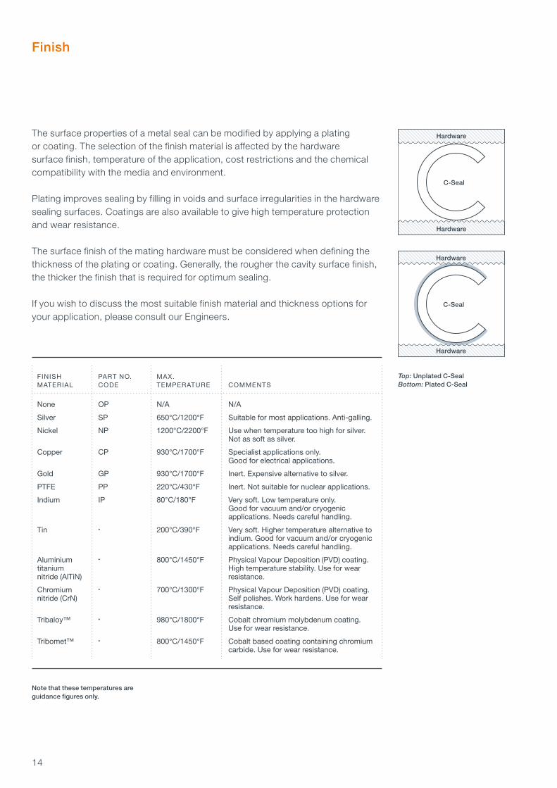
Top: Unplated C-SealBottom: Plated C-Seal
Finish
C-Seal
Hardware
Hardware
C-Seal
Hardware
Hardware
Note that these temperatures are guidance figures only.
FINISH PART NO. MAX. MATERIAL CODE TEMPERATURE COMMENTS
None OP N/A N/A
Silver SP 650°C/1200°F Suitable for most applications. Anti-galling.
Nickel NP 1200°C/2200°F Use when temperature too high for silver. Not as soft as silver.
Copper CP 930°C/1700°F Specialist applications only. Good for electrical applications.
Gold GP 930°C/1700°F Inert. Expensive alternative to silver.
PTFE PP 220°C/430°F Inert. Not suitable for nuclear applications.
Indium IP 80°C/180°F Very soft. Low temperature only. Good for vacuum and/or cryogenic applications. Needs careful handling.
Tin • 200°C/390°F Very soft. Higher temperature alternative to indium. Good for vacuum and/or cryogenic applications. Needs careful handling.
Aluminium • 800°C/1450°F Physical Vapour Deposition (PVD) coating. titanium High temperature stability. Use for wear nitride (AlTiN) resistance.
Chromium • 700°C/1300°F Physical Vapour Deposition (PVD) coating. nitride (CrN) Self polishes. Work hardens. Use for wear resistance.
Tribaloy™ • 980°C/1800°F Cobalt chromium molybdenum coating. Use for wear resistance.
Tribomet™ • 800°C/1450°F Cobalt based coating containing chromium carbide. Use for wear resistance.
The surface properties of a metal seal can be modified by applying a plating or coating. The selection of the finish material is affected by the hardware surface finish, temperature of the application, cost restrictions and the chemical compatibility with the media and environment.
Plating improves sealing by filling in voids and surface irregularities in the hardware sealing surfaces. Coatings are also available to give high temperature protection and wear resistance.
The surface finish of the mating hardware must be considered when defining the thickness of the plating or coating. Generally, the rougher the cavity surface finish, the thicker the finish that is required for optimum sealing.
If you wish to discuss the most suitable finish material and thickness options for your application, please consult our Engineers.

15 Nic
ho
lso
ns
Installation Guidelines
The performance of a metal seal can be significantly affected by the hardware design, the hardware surface finish and the installation of the seal.
Corruseal gaskets are installed between two flat and parallel surfaces: either two flanges, or between a fitting and a flange, or under a bolt head.
Counterbore Groove Retaining Plate
SURFACE FINISH
Surface finish of the mating hardware should ideally be as shown in the table below. The smoother the finish, the better the sealing. High temperature, high pressure and vacuum applications require smoother hardware surface finishes. A turned finish with a circular lay is preferred as it does not produce radial leak paths across the sealing line.
Note that finish values shown are ideal maximum values. Seals will work with values above these but sealing performance will be reduced.
C Circular M.D Multi-Directional
Corru
seal
FINISH (Ra)
Micrometres 0.8 0.8 0.8 1.6 0.8 0.4 0.8 0.8 0.8
Microinches 32 32 32 63 32 16 32 32 32
Roughness Number N6 N6 N6 N7 N6 N5 N6 N6 N6
DIRECTION OF LAY C C C C C M.D C C C
Two
Ply
Reflex
seal
SEALSGASKETS
C-Sea
l
Corru
plus
Corru
plus
Sigma S
eal
E-Sea
l
Other seals are often designed to operate in a cavity. Typical cavity arrangements are:
Mult
i Bell
ow
Sea
l

16
Handling Instructions
As both seal and plating can be easily damaged, we would recommend the following:
– The seals are protected during storage, i.e. not stored with other components as this will cause unnecessary contact and potential damage.
– The seal should remain in the original packaging until time of use, even on the assembly line.
– Ideally, measuring should be kept to a minimum as accidental damage can occur to the seal and more easily the plating (if applicable).
– The conditions when installing the seal should be clean, i.e. clean hands and uncontaminated hardware. The hardware should be scratch free and cleaned with acetone or equivalent prior to installing the seal.
– Place the seal carefully in the hardware, preventing scraping of the seal/plating and avoiding unnecessary sealing surface contact.
– Careful assembly of the mating hardware is required, with compression applied incrementally and uniformly (bolts tightened in a cross fashion) around the seal circumference.

17 Nic
ho
lso
ns

18

19
Product DescriptionGasket SpecificationPart List (AGS 3870–3889)Part List (AGS 3890–3909)Part List (Corruseal Sealing Washers)Load
Gaskets
202223242527

20
Product Description
Corruseal and Reflexseal are a range of single or multi ply embossed metal gaskets designed to be compressed between two parallel flanges to create a seal.
These products can be designed to suit the required customer application geometry and operating environments. Tight tolerances and complex sealing arrangements can be solved with gaskets and the Reflexseal pushes those limits further in its abilities to accommodate vibration and cavity thermal growth.
The Corruseal gasket is a metal crush type gasket which utilises a triangular corrugation form to concentrate the load available to those specific areas that require sealing. The corrugation is positioned around the aperture to be sealed. When used with thin or weak flanges, support corrugations can be placed around the bolt holes to prevent flange distortion and help the gasket to compress evenly.
Support corrugation
In confined areas corrugations can be combined
Corrugation can be positioned on narrow land
Can seal any shape of hole
Individually sealed hole
Corruseal can be offered in single ply, two ply and three ply options.
Corruseal – Single PlyThe single ply, single sealing corrugation design is the simplest and cheapest form of design. They are generally used between strong and flat flange faces, with an even and well distributed bolt load available.

21
Part Properties
– Able to seal high and low temperatures and pressures– Few limitations on size, shape or flange width– Can be designed to seal circular, irregular and multi
aperture applications– A range of standard corrugations are available– Does not require a machined groove– Does not stick to mating faces– Good structural strength; will not blow out during use– Low cost in both prototype and production runs
ReflexsealThe Nicholsons Reflexseal provides additional flexible sealing benefits by introducing a sealing device which incorporates established resilient metal sealing technology, similar to the Corruplus seal, into multi-layer gasket manufacture. The standard three ply Reflexseal design consists of top and bottom ‘formed’ plys which are situated either side of a plain centre ply which controls the amount of compression the gasket receives. The thickness of the centre can vary according to the specific application. The Reflexseal is ideal for those demanding applications involving high temperatures and pressures where the crush type gaskets have reached their limits.
Corruseal – Three PlyThe three ply Corruseal design comprises a top and bottom layer which are mirror images of each other with a plain centre ply sandwiched between. The centre layer is often made from a different material to the top and bottom plys and its thickness can be varied to meet a specific gasket thickness. It is better suited than the single ply design for coping with flange distortion due to high temperatures, particularly if the bolting pattern is not ideal.
Corruseal – Two PlyTwo ply Corruseal comprises two layers which are spot welded together. Offering ‘open bore’ sealing, this design can utilise the pressure it is sealing against to further enhance the gasket performance. If balance corrugations around bolt holes are required they are only formed in the top ply.
Gas
kets

22
Gasket Specification
Nicholsons offer a range of Corruseal Gaskets which are approved standard parts for three bolt flanges. Further details for these part numbers, AGS 3870–AGS 3909, can be found on pages 23 to 24. Corruseal Sealing Washers for a range of standard bolt and thread sizes are listed on pages 25 to 26.
Bespoke Gaskets can be designed for specific applications. In this instance, Nicholsons are able to work with you to develop a design for your requirements. Please contact us for assistance.
1. MATERIAL TYPE
Gasket materials are selected according to service requirements. Stainless steel is the most suitable option for many applications, however, Aluminium is most suitable for Aluminium flanges. A larger range of Gasket material options are listed on page 12.
Typical material thickness is within the range 0.007" to 0.015".
AGS 3870–AGS 3889 are made from Cupro-Nickel 0.010" thick.AGS 3890–AGS 3909 are made from Stainless Steel 0.010" thick.Corruseal Sealing Washers are typically made from Stainless Steel 0.010" thick.
2. HEAT TREATMENT
The available heat treatment options for Gaskets are listed on page 13.
3. PLATING OR COATING
Uncoated Gaskets are suitable for use in many applications. However, there are applications where a plating or coating is applied to the gasket to improve performance. See page 14 for further details on the options available.
Not all plating or coating options are valid for Gaskets, please consult us if you require further information.
AGS 3870–AGS 3889 are uncoated.AGS 3890–AGS 3909 are silver plated to a thickness of 0.0004"/0.0006".Corruseal Sealing Washers are uncoated.
23
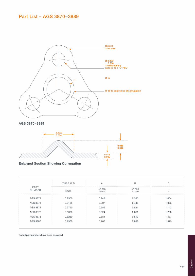
Part List – AGS 3870–3889
TUBE O.D A B C
+0.010 +0.020 -0.003 -0.020 •
AGS 3872 0.2500 0.248 0.386 1.004
AGS 3873 0.3125 0.307 0.445 1.063
AGS 3874 0.3750 0.386 0.524 1.142
AGS 3876 0.5000 0.524 0.661 1.280
AGS 3878 0.6250 0.681 0.819 1.437
AGS 3880 0.7500 0.760 0.898 1.575
PARTNUMBER NOM
R 0.3113 corners
Ø 0.293 0.2803 holes equally spaced on a ‘C’ PCD
Ø ‘B’ to centre line of corrugation
Ø ‘A’
Enlarged Section Showing Corrugation
0.0180.012
0.0110.009
0.0450.034
AGS 3870–3889
Not all part numbers have been assigned
Gas
kets
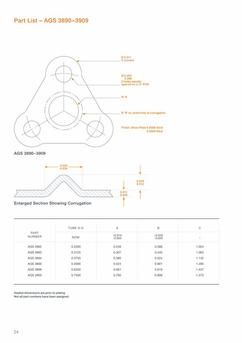
24
TUBE O.D A B C
+0.010 +0.020 -0.003 -0.020 •
AGS 3892 0.2500 0.248 0.386 1.004
AGS 3893 0.3125 0.307 0.445 1.063
AGS 3894 0.3750 0.386 0.524 1.142
AGS 3896 0.5000 0.524 0.661 1.280
AGS 3898 0.6250 0.681 0.819 1.437
AGS 3900 0.7500 0.760 0.898 1.575
PARTNUMBER NOM
Part List – AGS 3890–3909
R 0.3113 corners
Ø 0.293 0.2803 holes equally spaced on a ‘C’ PCD
Ø ‘B’ to centre line of corrugation
Finish: Silver Plate 0.0006 thick 0.0004 thick
Ø ‘A’
Enlarged Section Showing Corrugation
0.0450.034
AGS 3890–3909
Gasket dimensions are prior to platingNot all part numbers have been assigned
0.0180.012
0.0110.009
25
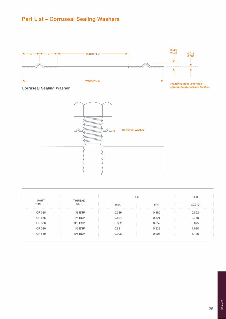
Part List – Corruseal Sealing Washers
I .D O.D
max. min. ±0.010
CP 535 1/8 BSP 0.389 0.386 0.562
CP 536 1/4 BSP 0.524 0.521 0.750
CP 538 3/8 BSP 0.662 0.659 0.875
CP 539 1/2 BSP 0.831 0.828 1.020
CP 540 5/8 BSP 0.908 0.905 1.125
PARTNUMBER
THREADSIZE
0.0290.022 0.011
0.009Washer I.D= =
Washer O.D
Corruseal Sealing WasherPlease contact us for non-standard materials and finishes
Corruseal Washer
Gas
kets

26
I .D O.D
max. min. ±0.010
CP 501 3/16 BSW 0.1935 0.1905 0.319
CP 502 1/4 BSW 0.2560 0.2530 0.438
CP 503 5/16 BSW 0.3185 0.3155 0.518
CP 504 3/8 BSW 0.3810 0.3780 0.592
CP 505 7/16 BSW 0.4435 0.4405 0.702
CP 506 1/2 BSW 0.5080 0.5030 0.812
CP 507 5/8 BSW 0.6330 0.6280 1.000
CP 508 3/4 BSW 0.7580 0.7530 1.190
CP 509 7/8 BSW 0.8830 0.8780 1.288
CP 510 1 BSW 1.0080 1.0030 1.468
CP 511 1 1/8 BSW 1.1350 1.1280 1.658
CP 512 1 1/4 BSW 1.2600 1.2530 1.845
CP 513 1 3/8 BSW 1.3850 1.3780 2.085
CP 514 1 1/2 BSW 1.5100 1.5030 2.200
CP 515 No 10/32 0.1960 0.1930 0.307
CP 516 1/4 UNF 0.2560 0.2530 0.430
CP 517 5/16 UNF 0.3185 0.3155 0.493
CP 518 3/8 UNF 0.3810 0.3780 0.554
CP 519 7/16 UNF 0.4435 0.4405 0.6170
CP 520 1/2 UNF 0.5080 0.5030 0.7420
CP 521 5/8 UNF 0.6330 0.6280 0.9290
CP 522 3/4 UNF 0.7580 0.7530 1.115
CP 523 7/8 UNF 0.8830 0.8780 1.300
CP 524 1 UNF 1.0080 1.0030 1.488
CP 525 1 1/8 UNF 1.1350 1.1280 1.756
CP 526 1 1/4 UNF 1.2600 1.2530 1.928
CP 527 1 3/8 UNF 1.3850 1.3780 2.119
CP 528 1 1/2 UNF 1.5100 1.5030 2.300
CP 530 6 BA 0.1152 0.1122 0.189
CP 531 4 BA 0.1467 0.1437 0.243
CP 532 2 BA 0.1900 0.1870 0.319
CP 533 0 BA 0.2412 0.2382 0.408
PARTNUMBER
BOLTSIZE
Part List – Corruseal Sealing Washers
27
Load
0
100
200
300
400
500
600
700
800
900
1000
INCONELS
STAINLESS STEEL
CUPRO-NICKEL
ALUMINIUM
MATERIAL
LB
F/I
N O
F C
OR
RU
GA
TIO
N
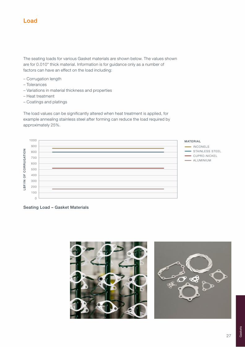
Seating Load – Gasket Materials
The seating loads for various Gasket materials are shown below. The values shown are for 0.010" thick material. Information is for guidance only as a number of factors can have an effect on the load including:
– Corrugation length– Tolerances– Variations in material thickness and properties– Heat treatment– Coatings and platings
The load values can be significantly altered when heat treatment is applied, for example annealing stainless steel after forming can reduce the load required by approximately 25%.
Gas
kets

28

29
Product DescriptionC-Seal SpecificationDiameter Codes (CI Series)Diameter Codes (CE Series)Diameter Codes (CA Series)Load
C-Seals
303135424952
30
Product Description
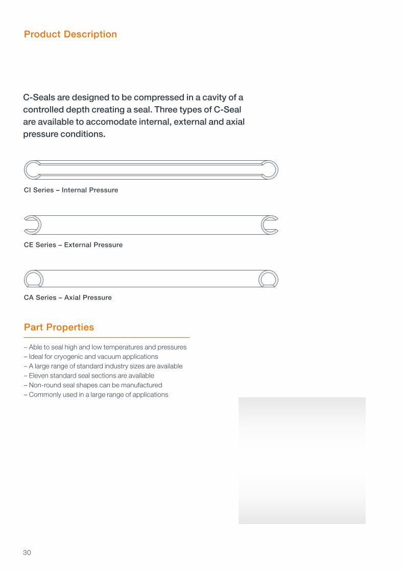
C-Seals are designed to be compressed in a cavity of a controlled depth creating a seal. Three types of C-Seal are available to accomodate internal, external and axial pressure conditions.
CI Series – Internal Pressure
CE Series – External Pressure
CA Series – Axial Pressure
Part Properties
– Able to seal high and low temperatures and pressures– Ideal for cryogenic and vacuum applications– A large range of standard industry sizes are available– Eleven standard seal sections are available– Non-round seal shapes can be manufactured– Commonly used in a large range of applications

31
Nicholsons offer a range of standard C-Seal part numbers. The part number system enables the selection of the correct seal for each application and installation using the permutations of size, material, plating, etc. An explanation of the Nicholsons C-Seal part number system is shown below.
Bespoke C-Seals can be designed for specific applications where the use of a standard C-Seal would not be appropriate due to shape, diameter, material type, snap fit requirements etc. Please contact us if you require a bespoke design or need any assistance specifying a standard C-Seal part number for your application.
1. SEAL TYPEThe type of seal and its orientation
2. DIAMETERThe seal and cavity diameters
3. SECTION AND MATERIAL THICKNESSThe seal section height and the standard material thickness options available for each
4. MATERIAL TYPEThe material type that we offer as standard
5. HEAT TREATMENTThe heat treatments that we offer as standard. Not all heat treatments are applicable to all materials
6. PLATING OR COATINGThe plating or coating type that we offer as standard
7. PLATING OR COATING THICKNESSThe thickness of the plating or coating
XX 0000 00 00 0 XX X
1. SEAL TYPEThe first section specifies the seal type:CI – Internal pressure face sealCE – External pressure face sealCA – Axial pressure face seal
PART NUMBER
2. DIAMETERThe second section specifies the seal and cavity diameter:For CI seals, see pages 35 to 41 for details of sizesFor CE seals, see pages 42 to 48 for details of sizesFor CA seals, see pages 50 to 51 for details of sizes
C-Seal Specification
C-
Sea
ls

32
1/4
NOMINAL SEAL AXIAL SEAL FREE LENGTH HEIGHT (max.)
01 0.006 Thin Wall
02* 0.010 Standard
03 0.010 Thin Wall
04* 0.015 Standard
05 0.010 Thin Wall
06 0.015 Standard
07 0.020 Thick Wall
08 0.015 Thin Wall
09 0.020 Standard
10 0.020 Thin Wall
11 0.025 Standard
NOMINAL ACTUAL SEAL FREE SEAL FREE HEIGHT HEIGHT
01 0.006 Thin Wall
02* 0.010 Standard
03 0.010 Thin Wall
04* 0.015 Standard
05 0.010 Thin Wall
06 0.015 Standard
07 0.020 Thick Wall
08 0.015 Thin Wall
09 0.020 Standard
10 0.020 Thin Wall
11 0.025 Standard
3a. SECTION AND MATERIAL THICKNESS – CI AND CE SERIES
3b. SECTION AND MATERIAL THICKNESS – CA SERIES
*For Seals CI 0007, CE 0007, CA 0007, and smaller, standard material thickness is:0.006 for 1/16 free height0.010 for 3/32 free height
PART NO.CODE
CAVITYCORNERRADIUSR (max.)
CAVITYCORNERRADIUSR (max.)
CAVITYAXIAL
LENGTH(min.)
PART NO.CODE
MATERIALTHICKNESS
MATERIALTHICKNESS
CAVITY DEPTH
1/16
1/16 0.058 0.062
3/32
3/32 0.085 0.093
3/16
3/16 0.175
1/4
0.220 0.240
0.0200.0630.061
0.0510.049
0.0940.092
0.0770.073
0.1890.185
0.1550.149
0.2530.247
0.2050.199
0.1260.124
0.1040.099
0.020
0.070
0.070
0.090
0.090
0.030
0.030
0.045
0.0450.120
1/8
1/8 0.110
0.160

33
5. HEAT TREATMENTThe fifth section specifies the heat treatments that are available as standard.Not all heat treatments are applicable to all materials.
PART NO. CODE HEAT TREATMENT COMMENTS
1 Work Hardened Standard for Axial Pressure C-Seals
2 Short Cycle Precipitation Suitable for most Face C-Seals Heat Treatment
3 Long Cycle Precipitation Consider for very high temperature Heat Treatment and/or very arduous applications
4 Solution and Long Cycle Consider for very high temperature Precipitation Heat Treatment and/or very arduous applications
5 Customer Specification •
PART NO. CODE MATERIAL COMMENTS
11 Nimonic 80A Obsolete material
12 Inconel X750 Standard material for C-Seals
13 Stainless Steel •
14 Inconel 718 Standard material for C-Seals
4. MATERIAL TYPEThe fourth section specifies the material types that are offered.
6. PLATING OR COATINGThe sixth section specifies the plating or coating applied to the seal.Plating may be incomplete inside C section.
PART NO. CODE PLATING OR COATING COMMENTS
OP None •
SP Silver Suitable for most applications
NP Nickel •
CP Copper •
GP Gold Very expensive
LP Lead Soft. Max. temp. 150°C/300°F
PP PTFE Max. temp. 220°C/430°F
IP Indium Very soft. Low temp only
C-
Sea
ls

34
PART NO. PLATING OR CODE COATING THICKNESS COMMENTS
A Standard for Silver
B •
C •
D •
E Customer Specification Customer Specification
O None Use with Unplated Seals
7. PLATING OR COATING THICKNESSThe seventh section specifies the plating or coating thickness.
0.00100.0005
0.00150.0010
0.00250.0015
0.00300.0020

35
– Weld permitted
– Plating may be incomplete inside C section
– Seal diameters are an average and can be out of round in excess of tolerances
– See the C-Seal introduction pages for details of seal free height, cavity depth and radius R
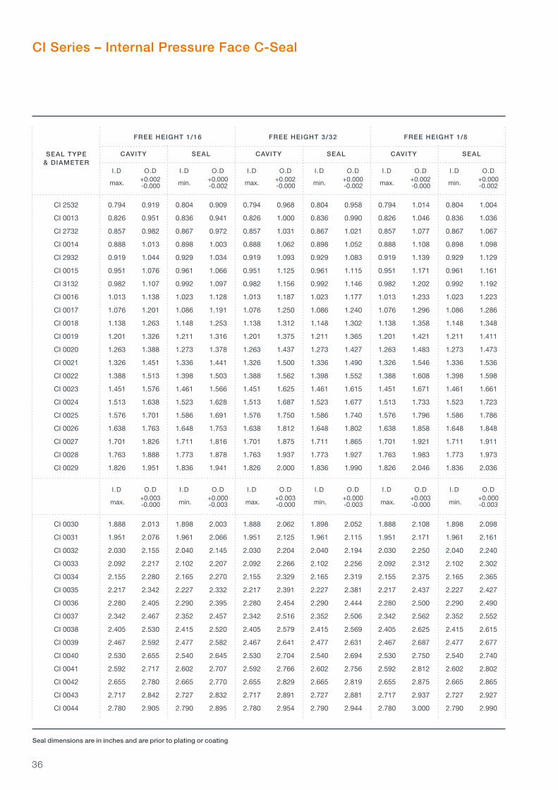
CI Series – Internal Pressure Face C-Seal
Seal dimensions are in inches and are prior to plating or coating
SEAL TYPE& DIAMETER
max. min. max. min. • • • •
Cavity O.D
Cavity I.D
Internal C-Seal cavity
Seal O.D
Seal I.D
Seal Free Height
Cavity Depth
R
max. min. max. min. max. min.
FREE HEIGHT 1/16 FREE HEIGHT 3/32 FREE HEIGHT 1/8
CAVITY SEAL CAVITY SEAL CAVITY SEAL
I.D O.D I.D O.D I.D O.D I.D O.D I.D O.D I.D O.D +0.001 +0.000 +0.001 +0.000 -0.000 -0.002 -0.000 -0.002
CI 0002 0.127 0.250 0.135 0.240 • • • • • • • •
CI 0532 0.158 0.281 0.166 0.271 • • • • • • • •
CI 0003 0.200 0.325 0.210 0.315 0.200 0.375 0.210 0.364 • • • •
CI 0732 0.231 0.356 0.241 0.346 0.231 0.406 0.241 0.395 • • • •
CI 0004 0.262 0.387 0.272 0.377 0.262 0.437 0.272 0.426 • • • •
CI 0932 0.293 0.418 0.303 0.408 0.293 0.468 0.303 0.457 • • • •
CI 0005 0.325 0.450 0.335 0.440 0.325 0.500 0.335 0.489 • • • •
CI 1132 0.356 0.481 0.366 0.471 0.356 0.531 0.366 0.520 • • • •
CI 0006 0.387 0.512 0.397 0.502 0.387 0.562 0.397 0.551 • • • •
CI 1332 0.418 0.543 0.428 0.533 0.418 0.593 0.428 0.582 • • • •
CI 0007 0.450 0.575 0.460 0.565 0.450 0.625 0.460 0.614 • • • •
CI 1532 0.481 0.606 0.491 0.596 0.481 0.656 0.491 0.645 • • • •
CI 0008 0.512 0.637 0.522 0.627 0.512 0.687 0.522 0.676 • • • •
CI 1732 0.543 0.688 0.553 0.658 0.543 0.718 0.553 0.707 • • • •
CI 0009 0.575 0.700 0.585 0.690 0.575 0.750 0.585 0.739 • • • •
CI 1932 0.606 0.731 0.616 0.721 0.606 0.781 0.616 0.770 • • • •
CI 0010 0.637 0.762 0.647 0.752 0.637 0.812 0.647 0.801 • • • •
CI 2132 0.668 0.793 0.678 0.783 0.668 0.843 0.678 0.832 • • • •
CI 0011 0.700 0.825 0.710 0.815 0.700 0.875 0.710 0.864 • • • •
CI 2332 0.731 0.856 0.741 0.846 0.731 0.906 0.741 0.895 • • • •
I.D O.D I.D O.D I.D O.D I.D O.D I.D O.D I.D O.D +0.002 +0.000 +0.002 +0.000 +0.002 +0.000 -0.000 -0.002 -0.000 -0.002 -0.000 -0.002
CI 0012 0.763 0.888 0.773 0.878 0.763 0.937 0.773 0.927 0.763 0.983 0.773 0.973
C-
Sea
ls
36
SEAL TYPE& DIAMETER
max. min. max. min. max. min.
CI Series – Internal Pressure Face C-Seal
max. min. max. min. max. min.
Seal dimensions are in inches and are prior to plating or coating
FREE HEIGHT 1/16 FREE HEIGHT 3/32 FREE HEIGHT 1/8
CAVITY SEAL CAVITY SEAL CAVITY SEAL
I.D O.D I.D O.D I.D O.D I.D O.D I.D O.D I.D O.D +0.002 +0.000 +0.002 +0.000 +0.002 +0.000 -0.000 -0.002 -0.000 -0.002 -0.000 -0.002
CI 2532 0.794 0.919 0.804 0.909 0.794 0.968 0.804 0.958 0.794 1.014 0.804 1.004
CI 0013 0.826 0.951 0.836 0.941 0.826 1.000 0.836 0.990 0.826 1.046 0.836 1.036
CI 2732 0.857 0.982 0.867 0.972 0.857 1.031 0.867 1.021 0.857 1.077 0.867 1.067
CI 0014 0.888 1.013 0.898 1.003 0.888 1.062 0.898 1.052 0.888 1.108 0.898 1.098
CI 2932 0.919 1.044 0.929 1.034 0.919 1.093 0.929 1.083 0.919 1.139 0.929 1.129
CI 0015 0.951 1.076 0.961 1.066 0.951 1.125 0.961 1.115 0.951 1.171 0.961 1.161
CI 3132 0.982 1.107 0.992 1.097 0.982 1.156 0.992 1.146 0.982 1.202 0.992 1.192
CI 0016 1.013 1.138 1.023 1.128 1.013 1.187 1.023 1.177 1.013 1.233 1.023 1.223
CI 0017 1.076 1.201 1.086 1.191 1.076 1.250 1.086 1.240 1.076 1.296 1.086 1.286
CI 0018 1.138 1.263 1.148 1.253 1.138 1.312 1.148 1.302 1.138 1.358 1.148 1.348
CI 0019 1.201 1.326 1.211 1.316 1.201 1.375 1.211 1.365 1.201 1.421 1.211 1.411
CI 0020 1.263 1.388 1.273 1.378 1.263 1.437 1.273 1.427 1.263 1.483 1.273 1.473
CI 0021 1.326 1.451 1.336 1.441 1.326 1.500 1.336 1.490 1.326 1.546 1.336 1.536
CI 0022 1.388 1.513 1.398 1.503 1.388 1.562 1.398 1.552 1.388 1.608 1.398 1.598
CI 0023 1.451 1.576 1.461 1.566 1.451 1.625 1.461 1.615 1.451 1.671 1.461 1.661
CI 0024 1.513 1.638 1.523 1.628 1.513 1.687 1.523 1.677 1.513 1.733 1.523 1.723
CI 0025 1.576 1.701 1.586 1.691 1.576 1.750 1.586 1.740 1.576 1.796 1.586 1.786
CI 0026 1.638 1.763 1.648 1.753 1.638 1.812 1.648 1.802 1.638 1.858 1.648 1.848
CI 0027 1.701 1.826 1.711 1.816 1.701 1.875 1.711 1.865 1.701 1.921 1.711 1.911
CI 0028 1.763 1.888 1.773 1.878 1.763 1.937 1.773 1.927 1.763 1.983 1.773 1.973
CI 0029 1.826 1.951 1.836 1.941 1.826 2.000 1.836 1.990 1.826 2.046 1.836 2.036
I.D O.D I.D O.D I.D O.D I.D O.D I.D O.D I.D O.D +0.003 +0.000 +0.003 +0.000 +0.003 +0.000 -0.000 -0.003 -0.000 -0.003 -0.000 -0.003
CI 0030 1.888 2.013 1.898 2.003 1.888 2.062 1.898 2.052 1.888 2.108 1.898 2.098
CI 0031 1.951 2.076 1.961 2.066 1.951 2.125 1.961 2.115 1.951 2.171 1.961 2.161
CI 0032 2.030 2.155 2.040 2.145 2.030 2.204 2.040 2.194 2.030 2.250 2.040 2.240
CI 0033 2.092 2.217 2.102 2.207 2.092 2.266 2.102 2.256 2.092 2.312 2.102 2.302
CI 0034 2.155 2.280 2.165 2.270 2.155 2.329 2.165 2.319 2.155 2.375 2.165 2.365
CI 0035 2.217 2.342 2.227 2.332 2.217 2.391 2.227 2.381 2.217 2.437 2.227 2.427
CI 0036 2.280 2.405 2.290 2.395 2.280 2.454 2.290 2.444 2.280 2.500 2.290 2.490
CI 0037 2.342 2.467 2.352 2.457 2.342 2.516 2.352 2.506 2.342 2.562 2.352 2.552
CI 0038 2.405 2.530 2.415 2.520 2.405 2.579 2.415 2.569 2.405 2.625 2.415 2.615
CI 0039 2.467 2.592 2.477 2.582 2.467 2.641 2.477 2.631 2.467 2.687 2.477 2.677
CI 0040 2.530 2.655 2.540 2.645 2.530 2.704 2.540 2.694 2.530 2.750 2.540 2.740
CI 0041 2.592 2.717 2.602 2.707 2.592 2.766 2.602 2.756 2.592 2.812 2.602 2.802
CI 0042 2.655 2.780 2.665 2.770 2.655 2.829 2.665 2.819 2.655 2.875 2.665 2.865
CI 0043 2.717 2.842 2.727 2.832 2.717 2.891 2.727 2.881 2.717 2.937 2.727 2.927
CI 0044 2.780 2.905 2.790 2.895 2.780 2.954 2.790 2.944 2.780 3.000 2.790 2.990

37
FREE HEIGHT 1/16 FREE HEIGHT 3/32 FREE HEIGHT 1/8
CAVITY SEAL CAVITY SEAL CAVITY SEAL
I.D O.D I.D O.D I.D O.D I.D O.D I.D O.D I.D O.D +0.003 +0.000 +0.003 +0.000 +0.003 +0.000 -0.000 -0.003 -0.000 -0.003 -0.000 -0.003
CI Series – Internal Pressure Face C-Seal
SEAL TYPE& DIAMETER
SEAL TYPE& DIAMETER
max. min. max. min. max. min.
max. min. max. min. max. min.
max. min. max. min. max. min.
Seal dimensions are in inches and are prior to plating or coating
CI 0045 2.842 2.967 2.852 2.957 2.842 3.016 2.852 3.006 2.842 3.062 2.852 3.052
CI 0046 2.905 3.020 2.915 3.010 2.905 3.079 2.915 3.069 2.905 3.125 2.915 3.115
CI 0047 2.967 3.082 2.977 3.072 2.967 3.141 2.977 3.131 2.967 3.187 2.977 3.177
CI 0048 3.030 3.145 3.040 3.135 3.030 3.204 3.040 3.194 3.030 3.250 3.040 3.240
I.D O.D I.D O.D I.D O.D I.D O.D I.D O.D I.D O.D +0.004 +0.000 +0.004 +0.000 +0.004 +0.000 -0.000 -0.004 -0.000 -0.004 -0.000 -0.004
CI 0049 3.092 3.207 3.102 3.197 3.092 3.266 3.102 3.256 3.092 3.312 3.102 3.302
CI 0050 3.155 3.270 3.165 3.260 3.155 3.329 3.165 3.319 3.155 3.375 3.165 3.365
CI 0051 3.217 3.332 3.227 3.322 3.217 3.391 3.227 3.381 3.217 3.437 3.227 3.427
CI 0052 3.280 3.395 3.290 3.385 3.280 3.454 3.290 3.444 3.280 3.500 3.290 3.490
CI 0053 3.342 3.457 3.352 3.447 3.342 3.516 3.352 3.506 3.342 3.562 3.352 3.552
CI 0054 3.405 3.520 3.415 3.510 3.405 3.579 3.415 3.569 3.405 3.625 3.415 3.615
CI 0055 3.467 3.582 3.477 3.572 3.467 3.641 3.477 3.631 3.467 3.687 3.477 3.667
CI 0056 3.530 3.645 3.540 3.635 3.530 3.704 3.540 3.694 3.530 3.750 3.540 3.740
FREE HEIGHT 1/ 8 FREE HEIGHT 3/16 FREE HEIGHT 1/4
CAVITY SEAL CAVITY SEAL CAVITY SEAL
I.D O.D I.D O.D I.D O.D I.D O.D I.D O.D I.D O.D +0.004 +0.000 +0.004 +0.000 +0.004 +0.000 -0.000 -0.004 -0.000 -0.004 -0.000 -0.004
CI 0057 3.592 3.812 3.602 3.802 3.592 3.912 3.602 3.902 • • • •
CI 0058 3.655 3.875 3.665 3.865 3.655 3.975 3.665 3.965 • • • •
CI 0059 3.717 3.937 3.727 3.927 3.717 4.037 3.727 4.027 • • • •
CI 0060 3.780 4.000 3.790 3.990 3.780 4.100 3.790 4.090 • • • •
CI 0061 3.842 4.062 3.852 4.052 3.842 4.162 3.852 4.152 • • • •
CI 0062 3.905 4.125 3.915 4.115 3.905 4.225 3.915 4.215 • • • •
CI 0063 3.967 4.187 3.977 4.177 3.967 4.287 3.977 4.277 • • • •
CI 0064 4.055 4.275 4.065 4.265 4.055 4.375 4.065 4.365 4.055 4.475 4.065 4.465
CI 0065 4.117 4.337 4.127 4.327 4.117 4.437 4.127 4.427 4.117 4.537 4.127 4.527
CI 0066 4.180 4.400 4.190 4.390 4.180 4.500 4.190 4.490 4.180 4.600 4.190 4.590
CI 0067 4.242 4.462 4.252 4.452 4.242 4.562 4.252 4.552 4.242 4.662 4.252 4.652
CI 0068 4.305 4.525 4.315 4.515 4.305 4.625 4.315 4.615 4.305 4.725 4.315 4.715
CI 0069 4.367 4.587 4.377 4.577 4.367 4.687 4.377 4.677 4.367 4.787 4.377 4.777
CI 0070 4.430 4.650 4.440 4.640 4.430 4.750 4.440 4.740 4.430 4.850 4.440 4.840
CI 0071 4.492 4.712 4.502 4.702 4.492 4.812 4.502 4.802 4.492 4.912 4.502 4.902
CI 0072 4.555 4.775 4.565 4.765 4.555 4.875 4.565 4.865 4.555 4.975 4.565 4.965
CI 0073 4.617 4.837 4.627 4.827 4.617 4.937 4.627 4.927 4.617 5.037 4.627 5.027
CI 0074 4.680 4.900 4.690 4.890 4.680 5.000 4.690 4.990 4.680 5.100 4.690 5.090
C-
Sea
ls

38
CI Series – Internal Pressure Face C-Seal
FREE HEIGHT 1/ 8 FREE HEIGHT 3/16 FREE HEIGHT 1/4
CAVITY SEAL CAVITY SEAL CAVITY SEAL
I.D O.D I.D O.D I.D O.D I.D O.D I.D O.D I.D O.D +0.004 +0.000 +0.004 +0.000 +0.004 +0.000 -0.000 -0.004 -0.000 -0.004 -0.000 -0.004
SEAL TYPE& DIAMETER
max. min. max. min. max. min.
Seal dimensions are in inches and are prior to plating or coating
CI 0075 4.742 4.962 4.752 4.952 4.742 5.062 4.752 5.052 4.742 5.162 4.752 5.152
CI 0076 4.805 5.025 4.815 5.015 4.805 5.125 4.815 5.115 4.805 5.225 4.815 5.215
CI 0077 4.867 5.087 4.877 5.077 4.867 5.187 4.877 5.177 4.867 5.287 4.877 5.277
CI 0078 4.930 5.150 4.940 5.140 4.930 5.250 4.940 5.240 4.930 5.350 4.940 5.340
CI 0079 4.992 5.212 5.002 5.202 4.992 5.312 5.002 5.302 4.992 5.412 5.002 5.402
CI 0080 5.055 5.275 5.065 5.265 5.055 5.375 5.065 5.365 5.055 5.475 5.065 5.465
I.D O.D I.D O.D I.D O.D I.D O.D I.D O.D I.D O.D +0.006 +0.000 +0.006 +0.000 +0.006 +0.000 -0.000 -0.006 -0.000 -0.006 -0.000 -0.006
CI 0081 5.117 5.337 5.127 5.327 5.117 5.437 5.127 5.427 5.117 5.537 5.127 5.527
CI 0082 5.180 5.400 5.190 5.390 5.180 5.500 5.190 5.490 5.180 5.600 5.190 5.590
CI 0083 5.242 5.462 5.252 5.452 5.242 5.562 5.252 5.552 5.242 5.662 5.252 5.652
CI 0084 5.305 5.525 5.315 5.515 5.305 5.625 5.315 5.615 5.305 5.725 5.315 5.715
CI 0085 5.367 5.587 5.377 5.577 5.367 5.687 5.377 5.677 5.367 5.787 5.377 5.777
CI 0086 5.430 5.650 5.440 5.640 5.430 5.750 5.440 5.740 5.430 5.850 5.440 5.840
CI 0087 5.492 5.712 5.502 5.702 5.492 5.812 5.502 5.802 5.492 5.912 5.502 5.902
CI 0088 5.555 5.775 5.565 5.765 5.555 5.875 5.565 5.865 5.555 5.975 5.565 5.965
CI 0089 5.617 5.837 5.627 5.827 5.617 5.937 5.627 5.927 5.617 6.037 5.627 6.027
CI 0090 5.680 5.900 5.690 5.890 5.680 6.000 5.690 5.990 5.680 6.100 5.690 6.090
CI 0092 5.805 6.025 5.815 6.015 5.805 6.125 5.815 6.115 5.805 6.225 5.815 6.215
CI 0094 5.930 6.150 5.940 6.140 5.930 6.250 5.940 6.240 5.930 6.350 5.940 6.340
CI 0096 6.055 6.275 6.065 6.265 6.055 6.375 6.065 6.365 6.055 6.475 6.065 6.465
CI 0098 6.180 6.400 6.190 6.390 6.180 6.500 6.190 6.490 6.180 6.600 6.190 6.590
CI 0100 6.305 6.525 6.315 6.515 6.305 6.625 6.315 6.615 6.305 6.725 6.315 6.715
CI 0102 6.430 6.650 6.440 6.640 6.430 6.750 6.440 6.740 6.430 6.850 6.440 6.840
CI 0104 6.555 6.775 6.565 6.765 6.555 6.875 6.565 6.865 6.555 6.975 6.565 6.965
CI 0106 6.680 6.900 6.690 6.890 6.680 7.000 6.690 6.990 6.680 7.100 6.690 7.090
CI 0108 6.805 7.025 6.815 7.015 6.085 7.125 6.815 7.115 6.805 7.225 6.815 7.215
CI 0110 6.930 7.150 6.940 7.140 6.930 7.250 6.940 7.240 6.930 7.350 6.940 7.340
CI 0112 7.055 7.275 7.065 7.265 7.055 7.375 7.065 7.365 7.055 7.475 7.065 7.465
I.D O.D I.D O.D I.D O.D I.D O.D I.D O.D I.D O.D +0.008 +0.000 +0.008 +0.000 +0.008 +0.000 -0.000 -0.008 -0.000 -0.008 -0.000 -0.008
CI 0114 7.180 7.400 7.190 7.390 7.180 7.500 7.190 7.490 7.180 7.600 7.190 7.590
CI 0116 7.305 7.525 7.315 7.515 7.305 7.625 7.315 7.615 7.305 7.725 7.315 7.715
CI 0118 7.430 7.650 7.440 7.640 7.430 7.750 7.440 7.740 7.430 7.850 7.440 7.840
CI 0120 7.555 7.775 7.565 7.765 7.555 7.875 7.565 7.865 7.555 7.975 7.565 7.965
CI 0122 7.680 7.900 7.690 7.890 7.680 8.000 7.690 7.990 7.680 8.100 7.690 8.090
CI 0124 7.805 8.025 7.815 8.015 7.805 8.125 7.815 8.115 7.805 8.225 7.815 8.215
max. min. max. min. max. min.
max. min. max. min. max. min.

39
CI 0126 7.930 8.150 7.940 8.140 7.930 8.250 7.940 8.240 7.930 8.350 7.940 8.340
CI 0128 8.055 8.275 8.065 8.265 8.055 8.375 8.065 8.365 8.055 8.475 8.065 8.465
CI 0130 8.180 8.400 8.190 8.390 8.180 8.500 8.190 8.490 8.180 8.600 8.190 8.590
CI 0132 8.305 8.525 8.315 8.515 8.305 8.625 8.315 8.615 8.305 8.725 8.315 8.715
CI 0134 8.430 8.650 8.440 8.640 8.430 8.750 8.440 8.740 8.430 8.850 8.440 8.840
CI 0136 8.555 8.775 8.565 8.765 8.555 8.875 8.565 8.865 8.555 8.975 8.565 8.965
CI 0138 8.680 8.900 8.690 8.890 8.680 9.000 8.690 8.990 8.680 9.100 8.690 9.090
CI 0140 8.805 9.025 8.815 9.015 8.805 9.125 8.815 9.115 8.805 9.225 8.815 9.215
CI 0142 8.930 9.150 8.940 9.140 8.930 9.250 8.940 9.240 8.930 9.350 8.940 9.340
CI 0144 9.055 9.275 9.065 9.265 9.055 9.375 9.065 9.365 9.055 9.475 9.065 9.465
CI 0146 9.180 9.400 9.190 9.390 9.180 9.500 9.190 9.490 9.180 9.600 9.190 9.590
CI 0148 9.305 9.525 9.315 9.515 9.305 9.625 9.315 9.615 9.305 9.725 9.315 9.715
CI 0150 9.430 9.650 9.440 9.640 9.430 9.750 9.440 9.740 9.430 9.850 9.440 9.840
CI 0152 9.555 9.775 9.565 9.765 9.555 9.875 9.565 9.865 9.555 9.975 9.565 9.965
CI 0154 9.680 9.900 9.690 9.890 9.680 10.000 9.690 9.990 9.680 10.100 9.690 10.090
CI 0156 9.805 10.025 9.815 10.015 9.805 10.125 9.815 10.115 9.805 10.225 9.815 10.215
CI 0158 9.930 10.150 9.940 10.140 9.930 10.250 9.940 10.240 9.930 10.350 9.940 10.340
CI 0160 10.055 10.275 10.065 10.265 10.055 10.375 10.065 10.365 10.055 10.475 10.065 10.465
I.D O.D I.D O.D I.D O.D I.D O.D I.D O.D I.D O.D +0.012 +0.000 +0.012 +0.000 +0.012 +0.000 -0.000 -0.012 -0.000 -0.012 -0.000 -0.012
CI 0162 10.180 10.400 10.190 10.390 10.180 10.500 10.190 10.490 10.180 10.600 10.190 10.590
CI 0164 10.305 10.525 10.315 10.515 10.305 10.625 10.315 10.615 10.305 10.725 10.315 10.715
CI 0166 10.430 10.650 10.440 10.640 10.430 10.750 10.440 10.740 10.430 10.850 10.440 10.840
CI 0168 10.555 10.775 10.565 10.765 10.555 10.875 10.565 10.865 10.555 10.975 10.565 10.965
CI 0170 10.680 10.900 10.690 10.890 10.680 11.000 10.690 10.990 10.680 11.100 10.690 11.090
CI 0172 10.805 11.025 10.815 11.015 10.805 11.125 10.815 11.115 10.805 11.225 10.815 11.215
CI 0174 10.930 11.150 10.940 11.140 10.930 11.250 10.940 11.240 10.930 11.350 10.940 11.340
CI 0176 11.055 11.275 11.065 11.265 11.055 11.375 11.065 11.365 11.055 11.475 11.065 11.465
CI 0178 11.180 11.400 11.190 11.390 11.180 11.500 11.190 11.490 11.180 11.600 11.190 11.590
CI 0180 11.305 11.525 11.315 11.515 11.305 11.625 11.315 11.615 11.305 11.725 11.315 11.715
CI 0182 11.430 11.650 11.440 11.640 11.430 11.750 11.440 11.740 11.430 11.850 11.440 11.840
CI 0184 11.555 11.775 11.565 11.765 11.555 11.875 11.565 11.865 11.555 11.975 11.565 11.965
CI 0186 11.680 11.900 11.690 11.890 11.680 12.000 11.690 11.990 11.680 12.100 11.690 12.090
CI 0188 11.805 12.025 11.815 12.015 11.805 12.125 11.815 12.115 11.805 12.225 11.815 12.215
CI 0190 11.930 12.150 11.940 12.140 11.930 12.250 11.940 12.240 11.930 12.350 11.940 12.340
CI 0192 12.055 12.275 12.065 12.265 12.055 12.375 12.065 12.365 12.055 12.475 12.065 12.465
CI 0194 12.180 12.400 12.190 12.390 12.180 12.500 12.190 12.490 12.180 12.600 12.190 12.590
CI 0196 12.305 12.525 12.315 12.515 12.305 12.625 12.315 12.615 12.305 12.725 12.315 12.715
CI Series – Internal Pressure Face C-Seal
FREE HEIGHT 1/ 8 FREE HEIGHT 3/16 FREE HEIGHT 1/4
CAVITY SEAL CAVITY SEAL CAVITY SEAL
I.D O.D I.D O.D I.D O.D I.D O.D I.D O.D I.D O.D +0.008 +0.000 +0.008 +0.000 +0.008 +0.000 -0.000 -0.008 -0.000 -0.008 -0.000 -0.008
SEAL TYPE& DIAMETER
max. min. max. min. max. min.
Seal dimensions are in inches and are prior to plating or coating
max. min. max. min. max. min.
C-
Sea
ls

40
CI Series – Internal Pressure Face C-Seal
CI 0198 12.430 12.650 12.440 12.640 12.430 12.750 12.440 12.740 12.430 12.850 12.440 12.840
CI 0200 12.555 12.775 12.565 12.765 12.555 12.875 12.565 12.865 12.555 12.975 12.565 12.965
CI 0202 12.680 12.900 12.690 12.890 12.680 13.000 12.690 12.990 12.680 13.100 12.690 13.090
CI 0204 12.805 13.025 12.815 13.015 12.805 13.125 12.815 13.115 12.805 13.225 12.815 13.215
CI 0206 12.930 13.150 12.940 13.140 12.930 13.250 12.940 13.240 12.930 13.350 12.940 13.340
CI 0208 13.055 13.275 13.065 13.265 13.055 13.375 13.065 13.365 13.055 13.475 13.065 13.465
CI 0210 13.180 13.400 13.190 13.390 13.180 13.500 13.190 13.490 13.180 13.600 13.190 13.590
CI 0212 13.305 13.525 13.315 13.515 13.305 13.625 13.315 13.615 13.305 13.725 13.315 13.715
CI 0214 13.430 13.650 13.440 13.640 13.430 13.750 13.440 13.740 13.430 13.850 13.440 13.840
CI 0216 13.555 13.775 13.565 13.765 13.555 13.875 13.565 13.865 13.555 13.975 13.565 13.965
CI 0218 13.680 13.900 13.690 13.890 13.680 14.000 13.690 13.990 13.680 14.100 13.690 14.090
CI 0220 13.805 14.025 13.815 14.015 13.805 14.125 13.815 14.115 13.805 14.225 13.815 14.215
CI 0222 13.930 14.150 13.940 14.140 13.930 14.250 13.940 14.240 13.930 14.350 13.940 14.340
CI 0224 14.055 14.275 14.065 14.265 14.055 14.375 14.065 14.365 14.055 14.475 14.065 14.465
CI 0226 14.180 14.400 14.190 14.390 14.180 14.500 14.190 14.490 14.180 14.600 14.190 14.590
CI 0228 14.305 14.525 14.315 14.515 14.305 14.625 14.315 14.615 14.305 14.725 14.315 14.715
CI 0230 14.430 14.650 14.440 14.640 14.430 14.750 14.440 14.740 14.430 14.850 14.440 14.840
CI 0232 14.555 14.775 14.565 14.765 14.555 14.875 14.565 14.865 14.555 14.975 14.565 14.965
CI 0234 14.680 14.900 14.690 14.890 14.680 15.000 14.690 14.990 14.680 15.100 14.690 15.090
CI 0236 14.805 15.025 14.815 15.015 14.805 15.125 14.815 15.115 14.805 15.225 14.815 15.215
CI 0238 14.930 15.150 14.940 15.140 14.930 15.250 14.940 15.240 14.930 15.350 14.940 15.340
CI 0240 15.055 15.275 15.065 15.265 15.055 15.375 15.065 15.365 15.055 15.475 15.065 15.465
I.D O.D I.D O.D I.D O.D I.D O.D I.D O.D I.D O.D +0.015 +0.000 +0.015 +0.000 +0.015 +0.000 -0.000 -0.015 -0.000 -0.015 -0.000 -0.015
CI 0242 15.180 15.400 15.190 15.390 15.180 15.500 15.190 15.490 15.180 15.600 15.190 15.590
CI 0244 15.305 15.525 15.315 15.515 15.305 15.625 15.315 15.615 15.305 15.725 15.315 15.715
CI 0246 15.430 15.650 15.440 15.640 15.430 15.750 15.440 15.740 15.430 15.850 15.440 15.840
CI 0248 15.555 15.775 15.565 15.765 15.555 15.875 15.565 15.865 15.555 15.975 15.565 15.965
CI 0250 15.680 15.900 15.690 15.890 15.680 16.000 15.690 15.990 15.680 16.100 15.690 16.090
CI 0252 15.805 16.025 15.815 16.015 15.805 16.125 15.815 16.115 15.805 16.225 15.815 16.215
CI 0254 15.930 16.150 15.940 16.140 15.930 16.250 15.940 16.240 15.930 16.350 15.940 16.340
CI 0256 16.055 16.275 16.065 16.265 16.055 16.375 16.065 16.365 16.055 16.475 16.065 16.465
CI 0258 16.180 16.400 16.190 16.390 16.180 16.500 16.190 16.490 16.180 16.600 16.190 16.590
CI 0260 16.305 16.525 16.315 16.515 16.305 16.625 16.315 16.615 16.305 16.725 16.315 16.715
CI 0262 16.430 16.650 16.440 16.640 16.430 16.750 16.440 16.740 16.430 16.850 16.440 16.840
CI 0264 16.555 16.775 16.565 16.765 16.555 16.875 16.565 16.865 16.555 16.975 16.565 16.965
CI 0266 16.680 16.900 16.690 16.890 16.680 17.000 16.690 16.990 16.680 17.100 16.690 17.090
CI 0268 16.805 17.025 16.815 17.015 16.805 17.125 16.815 17.115 16.805 17.225 16.815 17.215
FREE HEIGHT 1/ 8 FREE HEIGHT 3/16 FREE HEIGHT 1/4
CAVITY SEAL CAVITY SEAL CAVITY SEAL
I.D O.D I.D O.D I.D O.D I.D O.D I.D O.D I.D O.D +0.012 +0.000 +0.012 +0.000 +0.012 +0.000 -0.000 -0.012 -0.000 -0.012 -0.000 -0.012
SEAL TYPE& DIAMETER
max. min. max. min. max. min.
Seal dimensions are in inches and are prior to plating or coating
max. min. max. min. max. min.

41
CI Series – Internal Pressure Face C-Seal
CI 0270 16.930 17.150 16.940 17.140 16.930 17.250 16.940 17.240 16.930 17.350 16.940 17.340
CI 0272 17.055 17.275 17.065 17.265 17.055 17.375 17.065 17.365 17.055 17.475 17.065 17.465
CI 0274 17.180 17.400 17.190 17.390 17.180 17.500 17.190 17.490 17.180 17.600 17.190 17.590
CI 0276 17.305 17.525 17.315 17.515 17.305 17.625 17.315 17.615 17.305 17.725 17.315 17.715
CI 0278 17.430 17.650 17.440 17.640 17.430 17.750 17.440 17.740 17.430 17.850 17.440 17.840
CI 0280 17.555 17.775 17.565 17.765 17.555 17.875 17.565 17.865 17.555 17.975 17.565 17.965
CI 0282 17.680 17.900 17.690 17.890 17.680 18.000 17.690 17.990 17.680 18.100 17.690 18.090
CI 0284 17.805 18.025 17.815 18.015 17.805 18.125 17.815 18.115 17.805 18.225 17.815 18.215
CI 0286 17.930 18.150 17.940 18.140 17.930 18.250 17.940 18.240 17.930 18.350 17.940 18.340
CI 0288 18.055 18.275 18.065 18.265 18.055 18.375 18.065 18.365 18.055 18.475 18.065 18.465
CI 0290 18.180 18.400 18.190 18.390 18.180 18.500 18.190 18.490 18.180 18.600 18.190 18.590
CI 0292 18.305 18.525 18.315 18.515 18.305 18.625 18.315 18.615 18.305 18.725 18.315 18.715
CI 0294 18.430 18.650 18.440 18.640 18.430 18.750 18.440 18.740 18.430 18.850 18.440 18.840
CI 0296 18.555 18.775 18.565 18.765 18.555 18.875 18.565 18.865 18.555 18.975 18.565 18.965
CI 0298 18.680 18.900 18.690 18.890 18.680 19.000 18.690 18.990 18.680 19.100 18.690 19.090
CI 0300 18.805 19.025 18.815 19.015 18.805 19.125 18.815 19.115 18.805 19.225 18.815 19.215
CI 0302 18.930 19.150 18.940 19.140 18.930 19.250 18.940 19.240 18.930 19.350 18.940 19.340
CI 0304 19.055 19.275 19.065 19.265 19.055 19.375 19.065 19.365 19.055 19.475 19.065 19.465
CI 0306 19.180 19.400 19.190 19.390 19.180 19.500 19.190 19.490 19.180 19.600 19.190 19.590
CI 0308 19.305 19.525 19.315 19.515 19.305 19.625 19.315 19.615 19.305 19.725 19.315 19.715
CI 0310 19.430 19.650 19.440 19.640 19.430 19.750 19.440 19.740 19.430 19.850 19.440 19.840
CI 0312 19.555 19.775 19.565 19.765 19.555 19.875 19.565 19.865 19.555 19.975 19.565 19.965
CI 0314 19.680 19.900 19.690 19.890 19.680 20.000 19.690 19.990 19.680 20.100 19.690 20.090
CI 0316 19.805 20.025 19.815 20.015 19.805 20.125 19.815 20.115 19.805 20.225 19.815 20.215
CI 0318 19.930 20.150 19.940 20.140 19.930 20.250 19.940 20.240 19.930 20.350 19.940 20.340
FREE HEIGHT 1/ 8 FREE HEIGHT 3/16 FREE HEIGHT 1/4
CAVITY SEAL CAVITY SEAL CAVITY SEAL
I.D O.D I.D O.D I.D O.D I.D O.D I.D O.D I.D O.D +0.015 +0.000 +0.015 +0.000 +0.015 +0.000 -0.000 -0.015 -0.000 -0.015 -0.000 -0.015
SEAL TYPE& DIAMETER
max. min. max. min. max. min.
Seal dimensions are in inches and are prior to plating or coatingC
- S
eals

42
CE Series – External Pressure Face C-Seal
Cavity O.D
Cavity I.D
External C-Seal Cavity
Seal O.D
Seal I.D
Seal Free Height
Cavity Depth
R
– Weld permitted
– Plating may be incomplete inside C section
– Seal diameters are an average and can be out of round in excess of tolerances
– See the C-Seal introduction pages for details of seal free height, cavity depth and radius R
Seal dimensions are in inches and are prior to plating or coating
SEAL TYPE& DIAMETER
min. max. min. max. • • • •
FREE HEIGHT 1/16 FREE HEIGHT 3/32 FREE HEIGHT 1/8
CAVITY SEAL CAVITY SEAL CAVITY SEAL
I.D O.D I.D O.D I.D O.D I.D O.D I.D O.D I.D O.D +0.000 +0.002 +0.000 +0.002 -0.001 -0.000 -0.001 -0.000
CE 0002 0.116 0.244 0.128 0.233 • • • • • • • •
CE 0532 0.147 0.275 0.159 0.264 • • • • • • • •
CE 0003 0.179 0.307 0.191 0.296 0.179 0.366 0.191 0.351 • • • •
CE 0732 0.209 0.338 0.221 0.327 0.209 0.397 0.221 0.381 • • • •
CE 0004 0.240 0.369 0.252 0.358 0.240 0.428 0.252 0.412 • • • •
CE 0932 0.271 0.400 0.283 0.389 0.271 0.459 0.283 0.443 • • • •
CE 0005 0.303 0.432 0.315 0.421 0.303 0.491 0.315 0.475 • • • •
CE 1132 0.334 0.463 0.346 0.452 0.334 0.522 0.346 0.506 • • • •
CE 0006 0.365 0.494 0.377 0.483 0.365 0.553 0.377 0.537 • • • •
CE 1332 0.396 0.525 0.408 0.514 0.396 0.584 0.408 0.568 • • • •
CE 0007 0.428 0.557 0.440 0.546 0.428 0.616 0.440 0.600 • • • •
CE 1532 0.459 0.588 0.471 0.577 0.459 0.647 0.471 0.631 • • • •
CE 0008 0.490 0.619 0.502 0.608 0.490 0.678 0.502 0.662 • • • •
CE 1732 0.521 0.650 0.533 0.639 0.521 0.709 0.533 0.693 • • • •
CE 0009 0.553 0.682 0.565 0.671 0.533 0.741 0.565 0.725 • • • •
CE 1932 0.584 0.713 0.596 0.702 0.584 0.772 0.596 0.756 • • • •
CE 0010 0.615 0.744 0.627 0.733 0.615 0.803 0.627 0.787 • • • •
CE 2132 0.646 0.775 0.658 0.764 0.646 0.834 0.658 0.818 • • • •
CE 0011 0.677 0.807 0.689 0.796 0.677 0.866 0.689 0.849 • • • •
CE 2332 0.709 0.838 0.721 0.827 0.709 0.897 0.721 0.881 • • • •
I.D O.D I.D O.D I.D O.D I.D O.D I.D O.D I.D O.D +0.000 +0.002 +0.000 +0.002 +0.000 +0.002 -0.002 -0.000 -0.002 -0.000 -0.002 -0.000
CE 0012 0.740 0.869 0.752 0.858 0.740 0.928 0.752 0.912 0.740 0.987 0.752 0.953
min. max. min. max. min. max.

43
CE Series – External Pressure Face C-Seal
CE 2532 0.771 0.900 0.783 0.889 0.771 0.959 0.783 0.943 0.771 1.018 0.783 0.984
CE 0013 0.803 0.932 0.815 0.921 0.803 0.991 0.815 0.975 0.803 1.050 0.815 1.016
CE 2732 0.834 0.963 0.846 0.952 0.834 1.022 0.846 1.006 0.834 1.081 0.846 1.047
CE 0014 0.865 0.994 0.877 0.983 0.865 1.053 0.877 1.037 0.865 1.112 0.877 1.078
CE 2932 0.896 1.025 0.908 1.014 0.896 1.084 0.908 1.068 0.896 1.143 0.908 1.104
CE 0015 0.928 1.057 0.940 1.046 0.928 1.116 0.940 1.100 0.928 1.175 0.940 1.141
CE 3132 0.959 1.088 0.971 1.077 0.959 1.147 0.971 1.131 0.959 1.206 0.971 1.172
CE 0016 0.990 1.119 1.002 1.108 0.990 1.178 1.002 1.162 0.990 1.237 1.002 1.203
CE 0017 1.053 1.182 1.065 1.171 1.053 1.241 1.065 1.225 1.053 1.300 1.065 1.266
CE 0018 1.115 1.244 1.127 1.233 1.115 1.303 1.127 1.287 1.115 1.362 1.127 1.328
CE 0019 1.179 1.307 1.191 1.296 1.179 1.366 1.191 1.351 1.179 1.426 1.191 1.392
CE 0020 1.240 1.369 1.252 1.358 1.240 1.428 1.252 1.412 1.240 1.487 1.252 1.453
CE 0021 1.303 1.432 1.315 1.421 1.303 1.491 1.315 1.475 1.303 1.550 1.315 1.516
CE 0022 1.365 1.494 1.377 1.483 1.365 1.553 1.377 1.537 1.365 1.612 1.377 1.578
CE 0023 1.428 1.557 1.440 1.546 1.428 1.616 1.440 1.600 1.428 1.675 1.440 1.641
CE 0024 1.490 1.619 1.502 1.608 1.490 1.678 1.502 1.662 1.490 1.737 1.502 1.703
CE 0025 1.553 1.682 1.565 1.671 1.553 1.741 1.565 1.725 1.553 1.800 1.565 1.766
CE 0026 1.615 1.744 1.627 1.733 1.615 1.803 1.627 1.787 1.615 1.862 1.627 1.828
CE 0027 1.678 1.807 1.690 1.796 1.678 1.866 1.690 1.850 1.678 1.925 1.690 1.891
CE 0028 1.740 1.869 1.752 1.858 1.740 1.928 1.752 1.912 1.740 1.987 1.752 1.953
CE 0029 1.803 1.932 1.815 1.921 1.803 1.991 1.815 1.975 1.803 2.050 1.815 2.016
I.D O.D I.D O.D I.D O.D I.D O.D I.D O.D I.D O.D +0.000 +0.003 +0.000 +0.003 +0.000 +0.003 -0.003 -0.000 -0.003 -0.000 -0.003 -0.000
CE 0030 1.865 1.994 1.877 1.983 1.865 2.053 1.877 2.037 1.865 2.112 1.877 2.078
CE 0031 1.928 2.057 1.940 2.046 1.928 2.116 1.940 2.100 1.928 2.175 1.940 2.141
CE 0032 1.991 2.119 2.003 2.108 1.991 2.178 2.003 2.163 1.991 2.237 2.003 2.203
CE 0033 2.050 2.182 2.066 2.171 2.050 2.241 2.066 2.226 2.050 2.300 2.066 2.266
CE 0034 2.112 2.244 2.128 2.233 2.112 2.303 2.128 2.288 2.112 2.362 2.128 2.328
CE 0035 2.175 2.307 2.191 2.296 2.175 2.366 2.191 2.351 2.175 2.425 2.191 2.391
CE 0036 2.237 2.369 2.253 2.358 2.237 2.428 2.253 2.413 2.237 2.487 2.253 2.453
CE 0037 2.299 2.432 2.315 2.421 2.299 2.491 2.315 2.476 2.299 2.550 2.315 2.515
CE 0038 2.362 2.494 2.378 2.483 2.362 2.553 2.378 2.538 2.362 2.612 2.378 2.578
CE 0039 2.425 2.557 2.441 2.546 2.425 2.616 2.441 2.601 2.425 2.675 2.441 2.641
CE 0040 2.487 2.619 2.503 2.608 2.487 2.678 2.503 2.663 2.487 2.737 2.503 2.703
CE 0041 2.550 2.682 2.566 2.671 2.550 2.741 2.566 2.726 2.550 2.800 2.566 2.766
CE 0042 2.612 2.744 2.628 2.733 2.612 2.803 2.628 2.788 2.612 2.862 2.628 2.828
CE 0043 2.675 2.807 2.691 2.796 2.675 2.866 2.691 2.851 2.675 2.925 2.691 2.891
CE 0044 2.737 2.869 2.753 2.858 2.737 2.928 2.753 2.913 2.737 2.987 2.753 2.953
FREE HEIGHT 1/ 16 FREE HEIGHT 3/32 FREE HEIGHT 1/8
CAVITY SEAL CAVITY SEAL CAVITY SEAL
I.D O.D I.D O.D I.D O.D I.D O.D I.D O.D I.D O.D +0.000 +0.002 +0.000 +0.002 +0.000 +0.002 -0.002 -0.000 -0.002 -0.000 -0.002 -0.000
SEAL TYPE& DIAMETER
min. max. min. max. min. max.
Seal dimensions are in inches and are prior to plating or coating
min. max. min. max. min. max.
C-
Sea
ls

44
SEAL TYPE& DIAMETER
CE Series – External Pressure Face C-Seal
CE 0045 2.800 2.932 2.816 2.921 2.800 2.991 2.816 2.976 2.800 3.050 2.816 3.016
CE 0046 2.862 2.994 2.878 2.983 2.862 3.053 2.878 3.038 2.862 3.112 2.878 3.078
CE 0047 2.925 3.057 2.941 3.046 2.925 3.116 2.941 3.101 2.925 3.175 2.941 3.141
CE 0048 2.987 3.119 3.003 3.108 2.987 3.178 3.003 3.163 2.987 3.237 3.003 3.203
I.D O.D I.D O.D I.D O.D I.D O.D I.D O.D I.D O.D +0.000 +0.004 +0.000 +0.004 +0.000 +0.004 -0.004 -0.000 -0.004 -0.000 -0.004 -0.000
CE 0049 3.050 3.182 3.066 3.171 3.050 3.241 3.066 3.226 3.050 3.300 3.066 3.266
CE 0050 3.112 3.244 3.128 3.233 3.112 3.303 3.128 3.288 3.112 3.362 3.128 3.328
CE 0051 3.175 3.307 3.191 3.296 3.175 3.366 3.191 3.351 3.175 3.425 3.191 3.391
CE 0052 3.237 3.369 3.253 3.358 3.237 3.428 3.253 3.413 3.237 3.487 3.253 3.453
CE 0053 3.300 3.432 3.316 3.421 3.300 3.491 3.316 3.476 3.300 3.550 3.316 3.516
CE 0054 3.362 3.494 3.378 3.483 3.362 3.553 3.378 3.538 3.362 3.612 3.378 3.578
CE 0055 3.425 3.557 3.441 3.546 3.425 3.616 3.441 3.601 3.425 3.675 3.441 3.641
CE 0056 3.487 3.619 3.503 3.608 3.487 3.678 3.503 3.663 3.487 3.737 3.503 3.703
FREE HEIGHT 1/ 8 FREE HEIGHT 3/16 FREE HEIGHT 1/4
CAVITY SEAL CAVITY SEAL CAVITY SEAL
I.D O.D I.D O.D I.D O.D I.D O.D I.D O.D I.D O.D +0.000 +0.004 +0.000 +0.004 +0.000 +0.004 -0.004 -0.000 -0.004 -0.000 -0.004 -0.000
CE 0057 3.550 3.800 3.566 3.766 3.550 3.919 3.566 3.867 • • • •
CE 0058 3.612 3.862 3.628 3.828 3.612 3.981 3.628 3.929 • • • •
CE 0059 3.675 3.925 3.691 3.891 3.675 4.044 3.691 3.992 • • • •
CE 0060 3.737 3.987 3.753 3.953 3.737 4.106 3.753 4.054 • • • •
CE 0061 3.800 4.050 3.816 4.016 3.800 4.169 3.816 4.117 • • • •
CE 0062 3.862 4.112 3.878 4.078 3.862 4.231 3.878 4.179 • • • •
CE 0063 3.925 4.175 3.941 4.141 3.925 4.294 3.941 4.242 • • • •
CE 0064 3.987 4.237 4.003 4.203 3.987 4.356 4.003 4.304 3.987 4.475 4.003 4.405
CE 0065 4.046 4.300 4.066 4.266 4.046 4.419 4.066 4.367 4.046 4.538 4.066 4.468
CE 0066 4.108 4.362 4.128 4.328 4.108 4.481 4.128 4.429 4.108 4.600 4.128 4.530
CE 0067 4.171 4.425 4.191 4.391 4.171 4.544 4.191 4.492 4.171 4.663 4.191 4.593
CE 0068 4.233 4.487 4.253 4.453 4.233 4.606 4.253 4.554 4.233 4.725 4.253 4.655
CE 0069 4.296 4.550 4.316 4.516 4.296 4.669 4.316 4.617 4.296 4.788 4.316 4.718
CE 0070 4.358 4.612 4.378 4.578 4.358 4.731 4.378 4.679 4.358 4.850 4.378 4.780
CE 0071 4.421 4.675 4.441 4.641 4.421 4.794 4.441 4.742 4.421 4.913 4.441 4.843
CE 0072 4.483 4.737 4.503 4.703 4.483 4.856 4.503 4.804 4.483 4.975 4.503 4.905
CE 0073 4.546 4.800 4.566 4.766 4.546 4.919 4.566 4.867 4.546 5.038 4.566 4.968
CE 0074 4.608 4.862 4.628 4.828 4.608 4.981 4.628 4.929 4.608 5.100 4.628 5.030
FREE HEIGHT 1/ 16 FREE HEIGHT 3/32 FREE HEIGHT 1/8
CAVITY SEAL CAVITY SEAL CAVITY SEAL
I.D O.D I.D O.D I.D O.D I.D O.D I.D O.D I.D O.D +0.000 +0.003 +0.000 +0.003 +0.000 +0.003 -0.003 -0.000 -0.003 -0.000 -0.003 -0.000
SEAL TYPE& DIAMETER
min. max. min. max. min. max.
Seal dimensions are in inches and are prior to plating or coating
min. max. min. max. min. max.
min. max. min. max. min. max.

45
CE Series – External Pressure Face C-Seal
CE 0075 4.671 4.925 4.691 4.891 4.671 5.044 4.691 4.992 4.671 5.163 4.691 5.093
CE 0076 4.733 4.987 4.753 4.953 4.733 5.106 4.753 5.054 4.733 5.225 4.753 5.155
CE 0077 4.796 5.050 4.816 5.016 4.796 5.169 4.816 5.117 4.796 5.288 4.816 5.218
CE 0078 4.858 5.112 4.878 5.078 4.858 5.231 4.878 5.179 4.858 5.350 4.878 5.280
CE 0079 4.921 5.175 4.941 5.141 4.921 5.294 4.941 5.242 4.921 5.413 4.941 5.343
CE 0080 4.983 5.237 5.003 5.203 4.983 5.356 5.003 5.304 4.983 5.475 5.003 5.405
I.D O.D I.D O.D I.D O.D I.D O.D I.D O.D I.D O.D +0.000 +0.006 +0.000 +0.006 +0.000 +0.006 -0.006 -0.000 -0.006 -0.000 -0.006 -0.000
CE 0081 5.046 5.300 5.066 5.266 5.046 5.419 5.066 5.367 5.046 5.538 5.066 5.468
CE 0082 5.108 5.362 5.128 5.328 5.108 5.481 5.128 5.429 5.108 5.600 5.128 5.530
CE 0083 5.171 5.425 5.191 5.391 5.171 5.544 5.191 5.492 5.171 5.663 5.191 5.593
CE 0084 5.233 5.487 5.253 5.453 5.233 5.606 5.253 5.554 5.233 5.725 5.253 5.655
CE 0085 5.296 5.550 5.316 5.516 5.296 5.669 5.316 5.617 5.296 5.788 5.316 5.718
CE 0086 5.358 5.612 5.378 5.578 5.358 5.731 5.378 5.679 5.358 5.850 5.378 5.780
CE 0087 5.421 5.675 5.441 5.641 5.421 5.794 5.441 5.742 5.421 5.913 5.441 5.843
CE 0088 5.483 5.737 5.503 5.703 5.483 5.856 5.503 5.804 5.483 5.975 5.503 5.905
CE 0089 5.546 5.800 5.566 5.766 5.546 5.919 5.566 5.867 5.546 6.038 5.566 5.968
CE 0090 5.608 5.862 5.628 5.828 5.608 5.981 5.628 5.929 5.608 6.100 5.628 6.030
CE 0092 5.733 5.987 5.753 5.953 5.733 6.106 5.753 6.054 5.733 6.225 5.753 6.155
CE 0094 5.858 6.112 5.878 6.078 5.858 6.231 5.878 6.179 5.858 6.350 5.878 6.280
CE 0096 5.983 6.237 6.003 6.203 5.983 6.356 6.003 6.304 5.983 6.475 6.003 6.405
CE 0098 6.108 6.362 6.128 6.328 6.108 6.481 6.128 6.429 6.108 6.600 6.128 6.530
CE 0100 6.233 6.487 6.253 6.453 6.233 6.606 6.253 6.554 6.233 6.725 6.253 6.655
CE 0102 6.358 6.612 6.378 6.578 6.358 6.731 6.378 6.679 6.358 6.850 6.378 6.780
CE 0104 6.483 6.737 6.503 6.703 6.483 6.856 6.503 6.804 6.483 6.975 6.503 6.905
CE 0106 6.608 6.862 6.628 6.828 6.608 6.981 6.628 6.929 6.608 7.100 6.628 7.030
CE 0108 6.733 6.987 6.753 6.953 6.733 7.106 6.753 7.054 6.733 7.225 6.753 7.155
CE 0110 6.858 7.112 6.878 7.078 6.858 7.231 6.878 7.179 6.858 7.350 6.878 7.280
CE 0112 6.983 7.237 7.003 7.203 6.983 7.356 7.003 7.304 6.983 7.475 7.003 7.405
I.D O.D I.D O.D I.D O.D I.D O.D I.D O.D I.D O.D +0.000 +0.008 +0.000 +0.008 +0.000 +0.008 -0.008 -0.000 -0.008 -0.000 -0.008 -0.000
CE 0114 7.108 7.362 7.128 7.328 7.108 7.481 7.128 7.429 7.108 7.600 7.128 7.530
CE 0016 7.233 7.487 7.253 7.453 7.233 7.606 7.253 7.554 7.233 7.725 7.253 7.655
CE 0118 7.358 7.612 7.378 7.578 7.358 7.731 7.378 7.679 7.358 7.850 7.378 7.780
CE 0120 7.483 7.737 7.503 7.703 7.483 7.856 7.503 7.804 7.483 7.975 7.503 7.905
CE 0122 7.608 7.862 7.628 7.828 7.608 7.981 7.628 7.929 7.608 8.100 7.628 8.030
CE 0124 7.733 7.987 7.753 7.953 7.733 8.106 7.753 8.054 7.733 8.225 7.753 8.155
FREE HEIGHT 1/ 8 FREE HEIGHT 3/16 FREE HEIGHT 1/4
CAVITY SEAL CAVITY SEAL CAVITY SEAL
I.D O.D I.D O.D I.D O.D I.D O.D I.D O.D I.D O.D +0.000 +0.004 +0.000 +0.004 +0.000 +0.004 -0.004 -0.000 -0.004 -0.000 -0.004 -0.000
SEAL TYPE& DIAMETER
Seal dimensions are in inches and are prior to plating or coating
min. max. min. max. min. max.
min. max. min. max. min. max.
min. max. min. max. min. max.
C-
Sea
ls

46
CE Series – External Pressure Face C-Seal
CE 0126 7.858 8.112 7.878 8.078 7.858 8.231 7.878 8.179 7.858 8.350 7.878 8.280
CE 0128 7.983 8.237 8.003 8.203 7.983 8.356 8.003 8.304 7.983 8.475 8.003 8.405
CE 0130 8.108 8.362 8.128 8.328 8.108 8.481 8.128 8.429 8.108 8.600 8.128 8.530
CE 0132 8.233 8.487 8.253 8.453 8.233 8.606 8.253 8.554 8.233 8.725 8.253 8.655
CE 0134 8.358 8.612 8.378 8.578 8.358 8.731 8.378 8.679 8.358 8.850 8.378 8.780
CE 0136 8.483 8.737 8.503 8.703 8.483 8.856 8.503 8.804 8.483 8.975 8.503 8.905
CE 0138 8.608 8.862 8.628 8.828 8.608 8.981 8.628 8.929 8.608 9.100 8.628 9.030
CE 0140 8.733 8.987 8.753 8.953 8.733 9.106 8.753 9.054 8.733 9.225 8.753 9.155
CE 0142 8.858 9.112 8.878 9.078 8.858 9.231 8.878 9.179 8.858 9.350 8.878 9.280
CE 0144 8.983 9.237 9.003 9.203 8.983 9.356 9.003 9.304 8.983 9.475 9.003 9.405
CE 0146 9.108 9.362 9.128 9.328 9.108 9.481 9.128 9.429 9.108 9.600 9.128 9.530
CE 0148 9.233 9.487 9.253 9.453 9.233 9.606 9.253 9.554 9.233 9.725 9.253 9.655
CE 0150 9.358 9.612 9.378 9.578 9.358 9.731 9.378 9.679 9.358 9.850 9.378 9.780
CE 0152 9.483 9.737 9.503 9.703 9.483 9.856 9.503 9.804 9.483 9.975 9.503 9.905
CE 0154 9.608 9.862 9.628 9.828 9.608 9.981 9.628 9.929 9.608 10.100 9.628 10.030
CE 0156 9.733 9.987 9.753 9.953 9.733 10.106 9.753 10.054 9.733 10.225 9.753 10.155
CE 0158 9.858 10.112 9.878 10.078 9.858 10.231 9.878 10.179 9.858 10.350 9.878 10.280
CE 0160 9.983 10.237 10.003 10.203 9.983 10.356 10.003 10.304 9.983 10.475 10.003 10.405
I.D O.D I.D O.D I.D O.D I.D O.D I.D O.D I.D O.D +0.000 +0.012 +0.000 +0.012 +0.000 +0.012 -0.012 -0.000 -0.012 -0.000 -0.012 -0.000
CE 0162 10.108 10.362 10.128 10.328 10.108 10.481 10.128 10.429 10.108 10.600 10.128 10.530
CE 0164 10.233 10.487 10.253 10.453 10.233 10.606 10.253 10.554 10.233 10.725 10.253 10.655
CE 0166 10.358 10.612 10.378 10.578 10.358 10.731 10.378 10.679 10.358 10.850 10.378 10.780
CE 0168 10.483 10.737 10.503 10.703 10.483 10.856 10.503 10.804 10.483 10.975 10.503 10.905
CE 0170 10.608 10.862 10.628 10.828 10.608 10.981 10.628 10.929 10.608 11.100 10.628 11.030
CE 0172 10.733 10.987 10.753 10.953 10.733 11.106 10.753 11.054 10.733 11.225 10.753 11.155
CE 0174 10.858 11.112 10.878 11.078 10.858 11.231 10.878 11.179 10.858 11.350 10.878 11.280
CE 0176 10.983 11.237 11.003 11.203 10.983 11.356 11.003 11.304 10.983 11.475 11.003 11.405
CE 0178 11.108 11.362 11.128 11.328 11.108 11.481 11.128 11.429 11.108 11.600 11.128 11.530
CE 0180 11.233 11.487 11.253 11.453 11.233 11.606 11.253 11.554 11.233 11.725 11.253 11.655
CE 0182 11.358 11.612 11.378 11.578 11.358 11.731 11.378 11.679 11.358 11.850 11.378 11.780
CE 0184 11.483 11.737 11.503 11.703 11.483 11.856 11.503 11.804 11.483 11.975 11.503 11.905
CE 0186 11.608 11.862 11.628 11.828 11.608 11.981 11.628 11.929 11.608 12.100 11.628 12.030
CE 0188 11.733 11.987 11.753 11.953 11.733 12.106 11.753 12.054 11.733 12.225 11.753 12.155
CE 0190 11.858 12.112 11.878 12.078 11.858 12.231 11.878 12.179 11.858 12.350 11.878 12.280
CE 0192 11.983 11.237 12.003 12.203 11.983 12.356 12.003 12.304 11.983 12.475 12.003 12.405
CE 0194 12.108 12.362 12.128 12.328 12.108 12.481 12.128 12.429 12.108 12.600 12.128 12.530
CE 0196 12.233 12.487 12.253 12.453 12.233 12.606 12.253 12.554 12.233 12.725 12.253 12.655
FREE HEIGHT 1/ 8 FREE HEIGHT 3/16 FREE HEIGHT 1/4
CAVITY SEAL CAVITY SEAL CAVITY SEAL
I.D O.D I.D O.D I.D O.D I.D O.D I.D O.D I.D O.D +0.000 +0.008 +0.000 +0.008 +0.000 +0.008 -0.008 -0.000 -0.008 -0.000 -0.008 -0.000
SEAL TYPE& DIAMETER
Seal dimensions are in inches and are prior to plating or coating
min. max. min. max. min. max.
min. max. min. max. min. max.

47
CE Series – External Pressure Face C-Seal
CE 0198 12.358 12.612 12.378 12.578 12.358 12.731 12.378 12.679 12.358 12.850 12.378 12.780
CE 0200 12.483 12.737 12.503 12.703 12.483 12.856 12.503 12.804 12.483 12.975 12.503 12.905
CE 0202 12.608 12.862 12.628 12.828 12.608 12.981 12.628 12.929 12.608 13.100 12.628 13.030
CE 0204 12.733 12.987 12.753 12.953 12.733 13.106 12.753 13.054 12.733 13.225 12.753 13.155
CE 0206 12.858 13.112 12.878 13.078 12.858 13.231 12.878 13.179 12.858 13.350 12.878 13.280
CE 0208 12.983 13.237 13.003 13.203 12.983 13.356 13.003 13.304 12.983 13.475 13.003 13.405
CE 0210 13.108 13.362 13.128 13.328 13.108 13.481 13.128 13.429 13.108 13.600 13.128 13.530
CE 0212 13.233 13.487 13.253 13.453 13.233 13.606 13.253 13.554 13.233 13.725 13.253 13.655
CE 0214 13.358 13.612 13.378 13.578 13.358 13.731 13.378 13.679 13.358 13.850 13.378 13.780
CE 0216 13.483 13.737 13.503 13.703 13.483 13.856 13.503 13.804 13.483 13.975 13.503 13.905
CE 0218 13.608 13.862 13.628 13.828 13.608 13.981 13.628 13.929 13.608 14.100 13.628 14.030
CE 0220 13.733 13.987 13.753 13.953 13.733 14.106 13.753 14.054 13.733 14.225 13.753 14.155
CE 0222 13.858 14.112 13.878 14.078 13.858 14.231 13.878 14.179 13.858 14.350 13.878 14.280
CE 0224 13.983 14.237 14.003 14.203 13.983 14.356 14.003 14.304 13.983 14.475 14.003 14.405
CE 0226 14.108 14.362 14.128 14.328 14.108 14.481 14.128 14.429 14.108 14.600 14.128 14.530
CE 0228 14.233 14.487 14.253 14.453 14.233 14.606 14.253 14.554 14.233 14.725 14.253 14.655
CE 0230 14.358 14.612 14.378 14.578 14.358 14.731 14.378 14.679 14.358 14.850 14.378 14.780
CE 0232 14.483 14.737 14.503 14.703 14.483 14.856 14.503 14.804 14.483 14.975 14.503 14.905
CE 0234 14.608 14.862 14.628 14.828 14.608 14.981 14.628 14.929 14.608 15.100 14.628 15.030
CE 0236 14.733 14.987 14.753 14.953 14.733 15.106 14.753 15.054 14.733 15.225 14.753 15.155
CE 0238 14.858 15.112 14.878 15.078 14.858 15.231 14.878 15.179 14.858 15.350 14.878 15.280
CE 0240 14.983 15.237 15.003 15.203 14.983 15.356 15.003 15.304 14.983 15.475 15.003 15.405
I.D O.D I.D O.D I.D O.D I.D O.D I.D O.D I.D O.D +0.000 +0.015 +0.000 +0.015 +0.000 +0.015 -0.015 -0.000 -0.015 -0.000 -0.015 -0.000
CE 0242 15.108 15.362 15.128 15.328 15.108 15.481 15.128 15.429 15.108 15.600 15.128 15.530
CE 0244 15.233 15.487 15.253 15.453 15.233 15.606 15.253 15.554 15.233 15.725 15.253 15.655
CE 0246 15.358 15.612 15.378 15.578 15.358 15.731 15.378 15.679 15.358 15.850 15.378 15.780
CE 0248 15.483 15.737 15.503 15.703 15.483 15.856 15.503 15.804 15.483 15.975 15.503 15.905
CE 0250 15.608 15.862 15.628 15.828 15.608 15.981 15.628 15.929 15.608 16.100 15.628 16.030
CE 0252 15.733 15.987 15.753 15.953 15.733 16.106 15.753 16.054 15.733 16.225 15.753 16.155
CE 0254 15.858 16.112 15.878 16.078 15.858 16.231 15.878 16.179 15.858 16.350 15.878 16.280
CE 0256 15.983 16.237 16.003 16.203 15.983 16.356 16.003 16.304 15.983 16.475 16.003 16.405
CE 0258 16.108 16.362 16.128 16.328 16.108 16.481 16.128 16.429 16.108 16.600 16.128 16.530
CE 0260 16.233 16.487 16.253 16.453 16.233 16.606 16.253 16.554 16.233 16.725 16.253 16.655
CE 0262 16.358 16.612 16.378 16.578 16.358 16.731 16.378 16.679 16.358 16.850 16.378 16.780
CE 0264 16.483 16.737 16.503 16.703 16.483 16.856 16.503 16.804 16.483 16.975 16.503 16.905
CE 0266 16.608 16.862 16.628 16.828 16.608 16.981 16.628 16.929 16.608 17.100 16.628 17.030
CE 0268 16.733 16.987 16.753 16.953 16.733 17.106 16.753 17.054 16.733 17.225 16.753 17.155
FREE HEIGHT 1/ 8 FREE HEIGHT 3/16 FREE HEIGHT 1/4
CAVITY SEAL CAVITY SEAL CAVITY SEAL
I.D O.D I.D O.D I.D O.D I.D O.D I.D O.D I.D O.D +0.000 +0.012 +0.000 +0.012 +0.000 +0.012 -0.012 -0.000 -0.012 -0.000 -0.012 -0.000
SEAL TYPE& DIAMETER
Seal dimensions are in inches and are prior to plating or coating
min. max. min. max. min. max.
min. max. min. max. min. max.
C-
Sea
ls

48
CE Series – External Pressure Face C-Seal
CE 0270 16.858 17.112 16.878 17.078 16.858 17.231 16.878 17.179 16.858 17.350 16.878 17.280
CE 0272 16.983 17.237 17.003 17.203 16.983 17.356 17.003 17.304 16.983 17.475 17.003 17.405
CE 0274 17.108 17.362 17.128 17.328 17.108 17.481 17.128 17.429 17.108 17.600 17.128 17.530
CE 0276 17.233 17.487 17.253 17.453 17.233 17.606 17.253 17.554 17.233 17.725 17.253 17.655
CE 0278 17.358 17.612 17.378 17.578 17.358 17.731 17.378 17.679 17.358 17.850 17.378 17.780
CE 0280 17.483 17.737 17.503 17.703 17.483 17.856 17.503 17.804 17.483 17.975 17.503 17.905
CE 0282 17.608 17.862 17.628 17.828 17.608 17.981 17.628 17.929 17.608 18.100 17.628 18.030
CE 0284 17.733 17.987 17.753 17.953 17.733 18.106 17.753 18.054 17.733 18.225 17.753 18.155
CE 0286 17.858 18.112 17.878 18.078 17.858 18.231 17.878 18.179 17.858 18.350 17.878 18.280
CE 0288 17.983 18.237 18.003 18.203 17.983 18.356 18.003 18.304 17.983 18.475 18.003 18.405
CE 0290 18.108 18.362 18.128 18.328 18.108 18.481 18.128 18.429 18.108 18.600 18.128 18.530
CE 0292 18.233 18.487 18.253 18.453 18.233 18.606 18.253 18.554 18.233 18.725 18.253 18.655
CE 0294 18.358 18.612 18.378 18.578 18.358 18.731 18.378 18.679 18.358 18.850 18.378 18.780
CE 0296 18.483 18.737 18.503 18.703 18.483 18.856 18.503 18.804 18.483 18.975 18.503 18.905
CE 0298 18.608 18.862 18.628 18.828 18.608 18.981 18.628 19.929 18.608 19.100 18.628 19.030
CE 0300 18.733 18.987 18.753 18.953 18.733 19.106 18.753 19.054 18.733 19.225 18.753 19.155
CE 0302 18.858 19.112 18.878 19.078 18.858 19.231 18.878 19.179 18.858 19.350 18.878 19.280
CE 0304 18.983 19.237 19.003 19.203 18.983 19.356 19.003 19.304 18.983 19.475 19.003 19.405
CE 0306 19.108 19.362 19.128 19.328 19.108 19.481 19.128 19.429 19.108 19.600 19.128 19.530
CE 0308 19.233 19.487 19.253 19.453 19.233 19.606 19.253 19.554 19.233 19.725 19.253 19.655
CE 0310 19.358 19.612 19.378 19.578 19.358 19.731 19.378 19.679 19.358 19.850 19.378 19.780
CE 0312 19.483 19.737 19.503 19.703 19.483 19.856 19.503 19.804 19.483 19.975 19.503 19.905
CE 0314 19.608 19.862 19.628 19.828 19.608 19.981 19.628 19.929 19.608 20.100 19.628 20.030
CE 0316 19.733 19.987 19.753 19.953 19.733 20.106 19.753 20.054 19.733 20.225 19.753 20.155
CE 0318 19.858 20.112 19.878 20.078 19.858 20.231 19.878 20.179 19.858 20.350 19.878 20.280
FREE HEIGHT 1/ 8 FREE HEIGHT 3/16 FREE HEIGHT 1/4
CAVITY SEAL CAVITY SEAL CAVITY SEAL
I.D O.D I.D O.D I.D O.D I.D O.D I.D O.D I.D O.D +0.000 +0.015 +0.000 +0.015 +0.000 +0.015 -0.015 -0.000 -0.015 -0.000 -0.015 -0.000
SEAL TYPE& DIAMETER
Seal dimensions are in inches and are prior to plating or coating
min. max. min. max. min. max.

49
CA Series – Axial C-Seal
Cavity O.D
Cavity I.D
Seal O.D
Cavity I.D
Seal Axial Length
CavityAxial
Length
15°
R
Axial C-Seal Cavity
Axial C-Seal
NominalSeal Free
HeightSeal I.D
Seal AxialLength
Seal O.D
– Weld permitted
– Plating may be incomplete inside C section
– Seal diameters are an average and can be out of round in excess of tolerances
– See the C-Seal introduction pages for details of seal free height, cavity depth and radius R
C-
Sea
ls

50
CA Series – Axial C-Seal
CA 0002 0.125 0.248 0.122 0.251 0.125 0.310 0.122 0.313 • • • •
CA 0003 0.187 0.310 0.184 0.313 0.187 0.373 0.184 0.376 • • • •
CA 0004 0.250 0.373 0.247 0.376 0.250 0.435 0.247 0.438 • • • •
CA 0005 0.312 0.435 0.309 0.438 0.312 0.498 0.309 0.501 • • • •
CA 0006 0.375 0.498 0.372 0.501 0.375 0.560 0.372 0.563 0.375 0.623 0.372 0.626
CA 0007 0.437 0.560 0.434 0.563 0.437 0.623 0.434 0.626 0.437 0.685 0.434 0.688
CA 0008 0.500 0.623 0.497 0.626 0.500 0.685 0.497 0.688 0.500 0.748 0.497 0.751
CA 0009 0.562 0.685 0.559 0.688 0.562 0.748 0.559 0.751 0.562 0.810 0.559 0.813
CA 0010 0.625 0.748 0.622 0.751 0.625 0.810 0.622 0.813 0.625 0.873 0.622 0.876
CA 0011 0.687 0.810 0.684 0.813 0.687 0.873 0.684 0.876 0.687 0.935 0.684 0.938
CA 0012 0.750 0.873 0.747 0.876 0.750 0.935 0.747 0.938 0.750 0.998 0.747 1.001
CA 0013 0.812 0.935 0.809 0.938 0.812 0.998 0.809 1.001 0.812 1.060 0.809 1.063
CA 0014 0.875 0.998 0.872 1.001 0.875 1.060 0.872 1.063 0.875 1.123 0.872 1.126
CA 0015 0.937 1.060 0.934 1.063 0.937 1.123 0.934 1.126 0.937 1.185 0.934 1.188
CA 0016 1.000 1.123 0.997 1.126 1.000 1.185 0.997 1.188 1.000 1.248 0.997 1.251
CA 0018 1.125 1.248 1.122 1.251 1.125 1.310 1.122 1.313 1.125 1.373 1.122 1.376
CA 0020 1.250 1.373 1.247 1.376 1.250 1.435 1.247 1.438 1.250 1.498 1.247 1.501
CA 0022 1.375 1.498 1.372 1.501 1.375 1.560 1.372 1.563 1.375 1.623 1.372 1.626
CA 0024 • • • • 1.500 1.685 1.497 1.688 1.500 1.748 1.497 1.751
CA 0026 • • • • 1.625 1.810 1.622 1.813 1.625 1.873 1.622 1.876
CA 0028 • • • • 1.750 1.935 1.747 1.938 1.750 1.998 1.747 2.001
CA 0030 • • • • 1.875 2.060 1.872 2.063 1.875 2.123 1.872 2.126
CA 0032 • • • • 2.000 2.185 1.997 2.188 2.000 2.248 1.997 2.251
CA 0034 • • • • 2.125 2.310 2.122 2.313 2.125 2.373 2.122 2.376
CA 0036 • • • • 2.250 2.435 2.247 2.438 2.250 2.498 2.247 2.501
CA 0038 • • • • 2.375 2.560 2.372 2.563 2.375 2.623 2.372 2.626
CA 0040 • • • • 2.500 2.685 2.497 2.688 2.500 2.748 2.497 2.751
CA 0042 • • • • 2.625 2.810 2.622 2.813 2.625 2.873 2.622 2.876
CA 0044 • • • • 2.750 2.935 2.747 2.938 2.750 2.998 2.747 3.001
CA 0046 • • • • 2.875 3.060 2.872 3.063 2.875 3.123 2.872 3.126
FREE HEIGHT 1/ 16 FREE HEIGHT 3/32 FREE HEIGHT 1/8
CAVITY SEAL CAVITY SEAL CAVITY SEAL
I.D O.D I.D O.D I.D O.D I.D O.D I.D O.D I.D O.D +0.000 +0.001 +0.001 +0.001 +0.000 +0.001 +0.001 +0.001 +0.000 +0.001 +0.001 +0.001 -0.001 -0.000 -0.001 -0.001 -0.001 -0.000 -0.001 -0.001 -0.001 -0.000 -0.001 -0.001
SEAL TYPE& DIAMETER
Seal dimensions are in inches and are prior to plating or coating
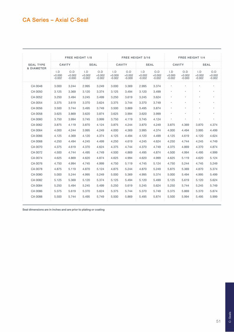
51
CA Series – Axial C-Seal
FREE HEIGHT 1/ 8 FREE HEIGHT 3/16 FREE HEIGHT 1/4
CAVITY SEAL CAVITY SEAL CAVITY SEAL
I.D O.D I.D O.D I.D O.D I.D O.D I.D O.D I.D O.D +0.000 +0.002 +0.002 +0.002 +0.000 +0.002 +0.002 +0.002 +0.000 +0.002 +0.002 +0.002 -0.002 -0.000 -0.002 -0.002 -0.002 -0.000 -0.002 -0.002 -0.002 -0.000 -0.002 -0.002
SEAL TYPE& DIAMETER
Seal dimensions are in inches and are prior to plating or coating
CA 0048 3.000 3.244 2.995 3.249 3.000 3.369 2.995 3.374 • • • •
CA 0050 3.125 3.369 3.120 3.374 3.125 3.494 3.120 3.499 • • • •
CA 0052 3.250 3.494 3.245 3.499 3.250 3.619 3.245 3.624 • • • •
CA 0054 3.375 3.619 3.370 3.624 3.375 3.744 3.370 3.749 • • • •
CA 0056 3.500 3.744 3.495 3.749 3.500 3.869 3.495 3.874 • • • •
CA 0058 3.625 3.869 3.620 3.874 3.625 3.994 3.620 3.999 • • • •
CA 0060 3.750 3.994 3.745 3.999 3.750 4.119 3.745 4.124 • • • •
CA 0062 3.875 4.119 3.870 4.124 3.875 4.244 3.870 4.249 3.875 4.369 3.870 4.374
CA 0064 4.000 4.244 3.995 4.249 4.000 4.369 3.995 4.374 4.000 4.494 3.995 4.499
CA 0066 4.125 4.369 4.120 4.374 4.125 4.494 4.120 4.499 4.125 4.619 4.120 4.624
CA 0068 4.250 4.494 4.245 4.499 4.250 4.619 4.245 4.624 4.250 4.744 4.245 4.749
CA 0070 4.375 4.619 4.370 4.624 4.375 4.744 4.370 4.749 4.375 4.869 4.370 4.874
CA 0072 4.500 4.744 4.495 4.749 4.500 4.869 4.495 4.874 4.500 4.994 4.495 4.999
CA 0074 4.625 4.869 4.620 4.874 4.625 4.994 4.620 4.999 4.625 5.119 4.620 5.124
CA 0076 4.750 4.994 4.745 4.999 4.750 5.119 4.745 5.124 4.750 5.244 4.745 5.249
CA 0078 4.875 5.119 4.870 5.124 4.875 5.244 4.870 5.249 5.875 5.369 4.870 5.374
CA 0080 5.000 5.244 4.995 5.249 5.000 5.369 4.995 5.374 5.000 5.494 4.995 5.499
CA 0082 5.125 5.369 5.120 5.374 5.125 5.494 5.120 5.499 5.125 5.619 5.120 5.624
CA 0084 5.250 5.494 5.245 5.499 5.250 5.619 5.245 5.624 5.250 5.744 5.245 5.749
CA 0086 5.375 5.619 5.370 5.624 5.375 5.744 5.370 5.749 5.375 5.869 5.370 5.874
CA 0088 5.500 5.744 5.495 5.749 5.500 5.869 5.495 5.874 5.500 5.994 5.495 5.999
C-
Sea
ls

52
Load
The seating loads for each seal section are shown below. The values shown are for long cycle precipitation heat treated Inconel 718 seals. These values are for guidance only as a number of factors can have a significant effect on the load including:
– Seal diameter– Seal free height– Cavity depth– Tolerances– Variations in material thickness and properties– Heat treatment– Coatings and platings
As a guideline, for work hardened Inconel 718, the values are reduced by approximately 50%. For long cycle precipitation heat treated Inconel X750, the values are reduced by approximately 25%.
0.0 0.2 0.4 0.6 0.8 1.0 1.2 1.4 1.6 1.8 2.0 2.2 2.4 2.6 2.8 3.0 3.225
50
75
100
125
150
175
200
225
250
275
300
325
0.010 IN
MATERIAL THICKNESS
0.006 IN
LO
AD
(L
BF
/IN
CIR
C.)
D IAMETER ( IN)
0.0 0.2 0.4 0.6 0.8 1.0 1.2 1.4 1.6 1.8 2.0 2.2 2.4 2.6 2.8 3.0 3.250
100
150
200
250
300
350
400
450
500
DIAMETER ( IN)
LO
AD
(L
BF
/IN
CIR
C.)
0.015 IN
MATERIAL THICKNESS
0.010 IN
1/16 Section Seating Load
3/32 Section Seating Load
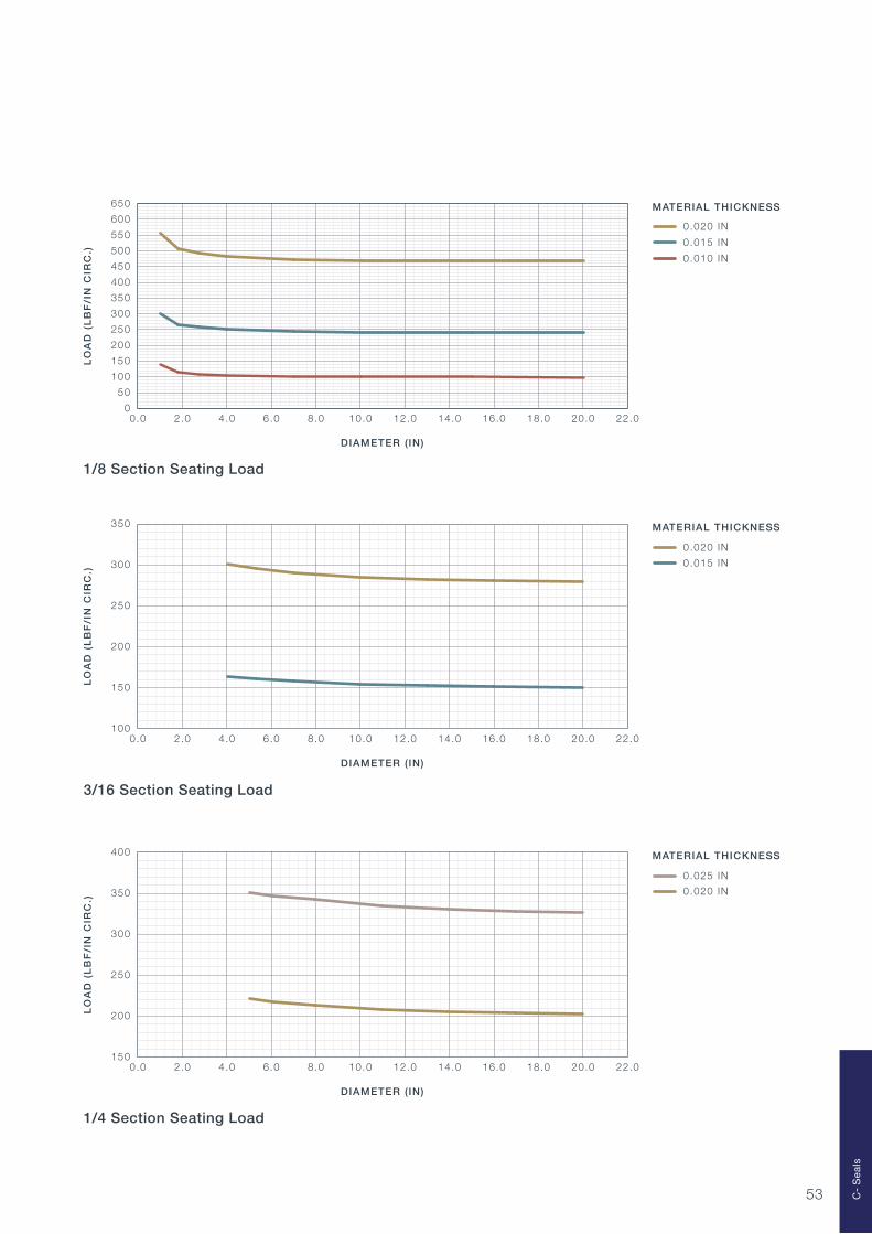
53
0.0 2.0 4.0 6.0 8.0 10.0 12.0 14.0 16.0 18.0 20.0 22.00
50
100
150
200
250
300
350
400
450
500
550
600
650
0.020 IN
0.015 IN
0.010 IN
DIAMETER ( IN)
LO
AD
(L
BF
/IN
CIR
C.)
MATERIAL THICKNESS
0.0 2.0 4.0 6.0 8.0 10.0 12.0 14.0 16.0 18.0 20.0 22.0100
150
200
250
300
350
0.020 IN
0.015 IN
DIAMETER ( IN)
MATERIAL THICKNESS
LO
AD
(L
BF
/IN
CIR
C.)
0.0 2.0 4.0 6.0 8.0 10.0 12.0 14.0 16.0 18.0 20.0 22.0150
200
250
300
350
400
0.025 IN
0.020 IN
DIAMETER ( IN)
LO
AD
(L
BF
/IN
CIR
C.)
MATERIAL THICKNESS
1/8 Section Seating Load
3/16 Section Seating Load
1/4 Section Seating Load
C-
Sea
ls

54

55
Product DescriptionBoss Seal SpecificationPart List
Boss Seals
565657

56
Boss Seals are a specialist range of C-Seals with an internal location washer designed for use with AND 10050 and MS 33649 type bosses.
Part Properties
– Available in a range of standard industry sizes– Fits in either direction at installation– Internal washer enables part to be screwed on to
the fitting and centres the seal in the boss– Part remains with fitting on disassembly
Product Description
Boss Seal Specification
Nicholsons offer a range of industry standard Boss Seal sizes. Available sizes are listed on page 57.
MATERIAL TYPEThe standard material for a Boss Seal is Inconel X750
HEAT TREATMENTThe standard treatment is work hardened.
PLATING OR COATINGThe standard Boss Seal is silver plated to a thickness of 0.0005"/0.0010". Other plating types are available on request. Please contact our Engineers for further information.
Boss Seal – Before Installation
Boss Seal
Boss Seals – After Installation
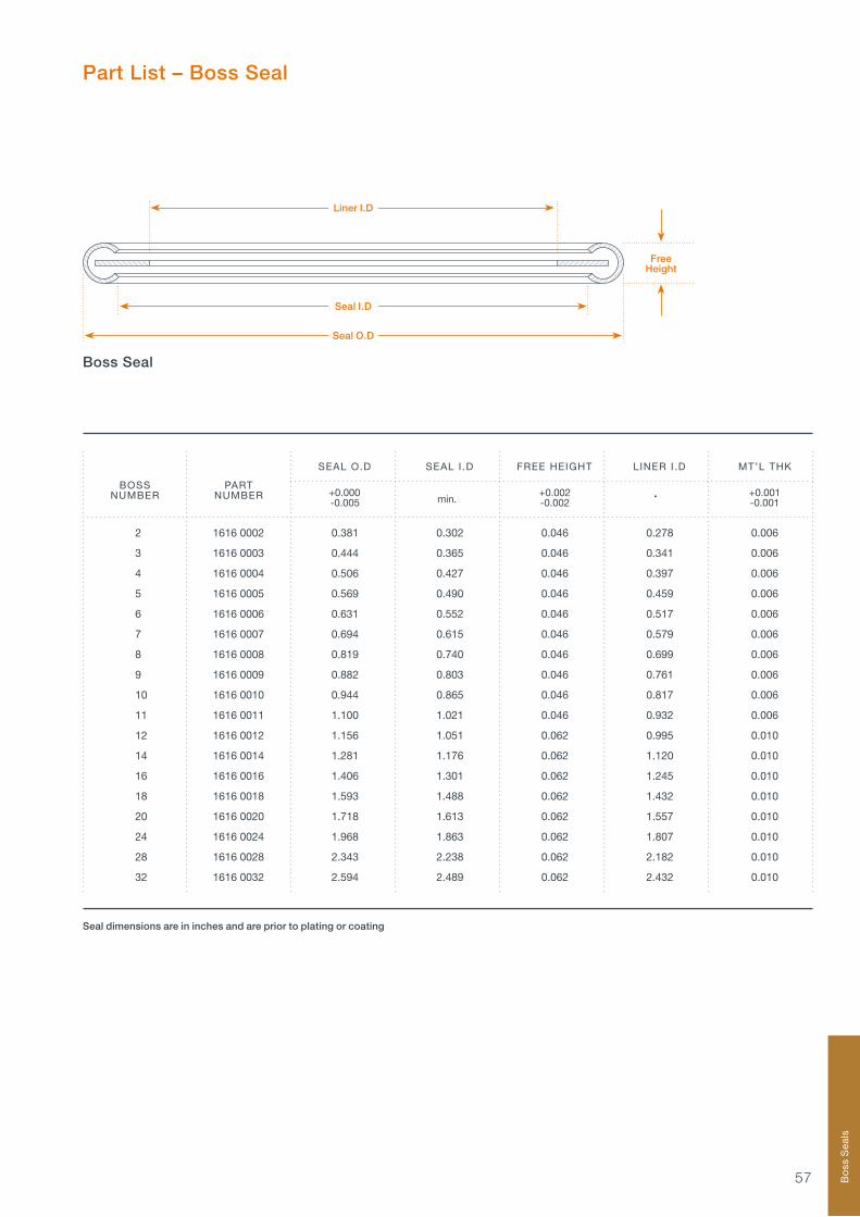
57 Bo
ss S
eals
Part List – Boss Seal
SEAL O.D SEAL I .D FREE HEIGHT LINER I .D MT’L THK
+0.000 +0.002 +0.001 -0.005 -0.002 -0.001
2 1616 0002 0.381 0.302 0.046 0.278 0.006
3 1616 0003 0.444 0.365 0.046 0.341 0.006
4 1616 0004 0.506 0.427 0.046 0.397 0.006
5 1616 0005 0.569 0.490 0.046 0.459 0.006
6 1616 0006 0.631 0.552 0.046 0.517 0.006
7 1616 0007 0.694 0.615 0.046 0.579 0.006
8 1616 0008 0.819 0.740 0.046 0.699 0.006
9 1616 0009 0.882 0.803 0.046 0.761 0.006
10 1616 0010 0.944 0.865 0.046 0.817 0.006
11 1616 0011 1.100 1.021 0.046 0.932 0.006
12 1616 0012 1.156 1.051 0.062 0.995 0.010
14 1616 0014 1.281 1.176 0.062 1.120 0.010
16 1616 0016 1.406 1.301 0.062 1.245 0.010
18 1616 0018 1.593 1.488 0.062 1.432 0.010
20 1616 0020 1.718 1.613 0.062 1.557 0.010
24 1616 0024 1.968 1.863 0.062 1.807 0.010
28 1616 0028 2.343 2.238 0.062 2.182 0.010
32 1616 0032 2.594 2.489 0.062 2.432 0.010
BOSSNUMBER
PARTNUMBER min. •
Boss Seal
Free Height
Liner I.D
Seal O.D
Seal I.D
Seal dimensions are in inches and are prior to plating or coating

58

59
Product DescriptionCorruplus SpecificationPart List (Small Section Corruplus Mk1 Seals)Part List (Large Section Corruplus Mk1 Seals)Part List (Corruplus Mk1 Seals for ‘V’ Band Couplings)Load
Corruplus
606162
65
68
69

60
Small Section Corruplus Mk1 Seals
Large Section Corruplus Mk1 Seals
Corruplus Mk1 Seals for ‘V’ Band Couplings
Corruplus Mk1 seals are a range of flexible metal seals designed to be compressed in a cavity of a controlled depth creating a seal.
The Corruplus Mk1 range of part numbers AS42700–AS42799 are approved as an SBAC industry standard part. Although normally used in a groove or counterbore, it is possible to use Corruplus with a retaining/nip control ring. The low clamp load characteristic of the seal makes it ideally suited for use in ‘V’ Band type couplings.
Three standard seal sections are available:
Part Properties
– Able to seal high and low temperatures and pressures– Flexible, low load seal with good recovery– A large range of standard sizes– Three standard seal sections available– All seals are individually pressure tested– Can be re-used. A Corruplus Test Rig is required– Fire proof operation
Product Description

61
Corruplus Specification
Nicholsons offer a range of Corruplus Mk1 seals in the three standard sections. Further information for small and large section ‘AS’ and ‘CPL’ Corruplus Mk1 seals can be found on pages 62 to 67. We also offer a series of CPL/V seals for ‘V’ Band Couplings (page 68) designed to suit a particular flange configuration.
Bespoke Corruplus can be designed for specific applications. In this instance, please contact us for assistance.
MATERIAL TYPEThe standard material for Corruplus is Inconel 718. Small section Corruplus are made from 0.012" material thickness.Large section Corruplus are made from 0.015" material thickness.For ‘V’ Band Coupling sections, 0.015" thick material is used.
HEAT TREATMENTThe standard treatment is Solution and Long Cycle Precipitation.
PLATING OR COATINGCorruplus are silver plated to a thickness of 0.002" min. The seal is given a high temperature bake to soften the silver plating. Nickel plating is an available option. Please contact us for further information.
Co
rru
plu
s

62
Small Section Corruplus Mk1 Seals
PARTNUMBER
max.
Cavity O.D
Cavity I.D
Seal O.D
R0.040max.
Small Section Corruplus Mk1 Cavity
Corruplus Mk1 Small Section
Seal I.D
0.010 min.
0.098 min.
0.0910.089
Seal O.D
0.088 max.
Seal I.D
Seal dimensions are in inches and apply after plating
CAVITY SEAL
I.D O.D I.D O.D +0.005 +0.010 +0.000 -0.000 -0.000 -0.010
CPL 107 0.118 0.407 0.145 0.405
CPL 108 0.149 0.438 0.176 0.436
CPL 109 0.211 0.500 0.238 0.498
AS42701 0.249 0.537 0.276 0.535
CPL 110 0.272 0.563 0.300 0.560
AS42702 0.288 0.577 0.315 0.575
AS42703 0.328 0.616 0.354 0.614
CPL 111 0.336 0.625 0.363 0.623
AS42704 0.367 0.656 0.394 0.654
CPL 112 0.397 0.688 0.425 0.685
AS42705 0.406 0.695 0.433 0.693
AS42706 0.446 0.734 0.472 0.732
CPL 113 0.461 0.750 0.488 0.748
AS42707 0.485 0.774 0.512 0.772
AS42708 0.524 0.813 0.551 0.811
AS42709 0.564 0.852 0.591 0.850

63
PARTNUMBER
max.
Small Section Corruplus Mk1 Seals
CAVITY SEAL
I.D O.D I.D O.D +0.005 +0.010 +0.000 -0.000 -0.000 -0.010
CPL 115 0.586 0.875 0.613 0.873
AS42710 0.603 0.892 0.630 0.890
AS42711 0.643 0.931 0.669 0.929
CPL 116 0.647 0.938 0.675 0.935
AS42712 0.682 0.970 0.709 0.969
CPL 117 0.711 1.000 0.738 0.998
AS42713 0.721 1.010 0.748 1.008
AS42714 0.761 1.049 0.787 1.047
CPL 118 0.772 1.063 0.800 1.060
AS42715 0.800 1.089 0.827 1.087
CPL 119 0.836 1.125 0.863 1.123
AS42716 0.839 1.128 0.866 1.126
AS42717 0.879 1.167 0.906 1.165
CPL 120 0.899 1.188 0.926 1.186
AS42718 0.918 1.207 0.945 1.205
AS42719 0.957 1.246 0.984 1.244
CPL 121 0.961 1.250 0.988 1.248
AS42720 0.997 1.285 1.024 1.283
CPL 122 1.022 1.313 1.050 1.310
AS42721 1.036 1.325 1.063 1.323
AS42722 1.076 1.364 1.102 1.362
CPL 123 1.086 1.375 1.113 1.373
AS42723 1.115 1.404 1.142 1.402
CPL 124 1.149 1.438 1.176 1.436
AS42724 1.154 1.443 1.181 1.441
AS42725 1.194 1.482 1.220 1.480
CPL 125 1.211 1.500 1.238 1.498
AS42726 1.233 1.522 1.260 1.520
AS42727 1.272 1.561 1.299 1.559
AS42728 1.312 1.600 1.339 1.598
CPL 127 1.336 1.625 1.363 1.623
AS42729 1.351 1.640 1.378 1.638
AS42730 1.391 1.679 1.417 1.677
CPL 128 1.398 1.688 1.425 1.686
AS42731 1.430 1.719 1.457 1.717
CPL 129 1.461 1.750 1.488 1.748
AS42732 1.469 1.758 1.496 1.756
AS42733 1.509 1.797 1.535 1.795
CPL 130 1.522 1.813 1.550 1.810
AS42734 1.548 1.837 1.575 1.835
AS42735 1.587 1.876 1.614 1.874
Seal dimensions are in inches and apply after plating
Co
rru
plu
s

64
PARTNUMBER
max.
CAVITY SEAL
I.D O.D I.D O.D +0.005 +0.010 +0.000 -0.000 -0.000 -0.010
AS42736 1.627 1.915 1.654 1.913
CPL 132 1.647 1.938 1.675 1.935
AS42737 1.666 1.955 1.693 1.953
AS42738 1.706 1.994 1.732 1.992
CPL 134 1.711 2.000 1.738 1.998
AS42739 1.745 2.033 1.772 2.031
CPL 135 1.772 2.063 1.800 2.060
AS42740 1.784 2.073 1.811 2.071
AS42741 1.824 2.112 1.850 2.110
CPL 136 1.835 2.126 1.863 2.123
AS42742 1.863 2.152 1.890 2.150
CPL 137 1.899 2.188 1.926 2.186
AS42743 1.902 2.191 1.929 2.189
AS42744 1.942 2.230 1.969 2.228
CPL 138 1.962 2.251 1.989 2.249
AS42745 1.981 2.270 2.008 2.268
AS42746 2.020 2.309 2.047 2.307
AS42747 2.060 2.348 2.087 2.346
AS42748 2.099 2.388 2.126 2.386
Seal dimensions are in inches and apply after plating
Small Section Corruplus Mk1 Seals

65
Large Section Corruplus Mk1 Seals
PARTNUMBER
max.
Cavity O.D
Cavity I.D
Seal O.D
R0.040max.
Large Section Corruplus Mk1 Cavity
Corruplus Mk1 Large Section
Seal I.D
0.010 min.
0.117 min.
0.1110.108
Seal O.D
0.107 max.
Seal I.D
CAVITY SEAL
I.D O.D I.D O.D +0.010 +0.010 +0.000 -0.000 -0.000 -0.010
CPL 227 1.998 2.382 2.030 2.380
CPL 228 2.123 2.507 2.155 2.505
AS42749 2.132 2.520 2.165 2.516
CPL 229 2.248 2.632 2.280 2.630
AS42750 2.329 2.717 2.362 2.713
CPL 230 2.373 2.757 2.405 2.755
CPL 231 2.498 2.882 2.530 2.880
AS42751 2.526 2.913 2.559 2.909
CPL 232 2.623 3.007 2.655 3.005
AS42752 2.722 3.110 2.756 3.106
CPL 233 2.748 3.132 2.780 3.130
CPL 234 2.873 3.257 2.905 3.255
AS42753 2.919 3.307 2.953 3.303
CPL 235 2.998 3.382 3.030 3.380
AS42754 3.116 3.504 3.150 3.500
Seal dimensions are in inches and apply after plating
Co
rru
plu
s

66
PARTNUMBER
max.
Large Section Corruplus Mk1 Seals
CAVITY SEAL
I.D O.D I.D O.D +0.010 +0.010 +0.000 -0.000 -0.000 -0.010
CPL 236 3.123 3.507 3.155 3.505
CPL 237 3.248 3.632 3.280 3.630
AS42755 3.313 3.701 3.346 3.697
CPL 238 3.373 3.757 3.405 3.755
CPL 239 3.498 3.882 3.530 3.880
AS42756 3.510 3.898 3.543 3.894
CPL 240 3.623 4.007 3.655 4.005
AS42757 3.707 4.094 3.740 4.091
CPL 241 3.748 4.132 3.780 4.130
CPL 242 3.873 4.257 3.905 4.255
AS42758 3.904 4.291 3.937 4.287
CPL 243 3.998 4.382 4.030 4.380
AS42759 4.100 4.488 4.134 4.484
CPL 244 4.123 4.507 4.155 4.505
CPL 245 4.248 4.632 4.280 4.630
AS42760 4.297 4.685 4.331 4.681
CPL 246 4.373 4.757 4.405 4.755
AS42761 4.494 4.882 4.528 4.878
CPL 248 4.623 5.007 4.655 5.005
AS42762 4.691 5.079 4.724 5.075
CPL 249 4.748 5.132 4.780 5.130
CPL 250 4.873 5.257 4.905 5.255
AS42763 4.888 5.276 4.921 5.272
CPL 251 4.998 5.382 5.030 5.380
AS42764 5.085 5.472 5.118 5.468
CPL 252 5.123 5.507 5.155 5.505
CPL 253 5.248 5.632 5.280 5.630
AS42765 5.281 5.669 5.315 5.665
CPL 254 5.373 5.757 5.405 5.755
AS42766 5.478 5.866 5.512 5.862
CPL 255 5.498 5.882 5.530 5.880
CPL 256 5.623 6.007 5.655 6.005
AS42767 5.675 6.063 5.709 6.059
CPL 257 5.748 6.132 5.780 6.130
AS42768 5.872 6.260 5.906 6.256
AS42769 6.069 6.457 6.102 6.453
AS42770 6.266 6.654 6.299 6.650
AS42771 6.463 6.850 6.496 6.846
AS42772 6.659 7.047 6.693 7.043
AS42773 6.856 7.244 6.890 7.240
Seal dimensions are in inches and apply after plating
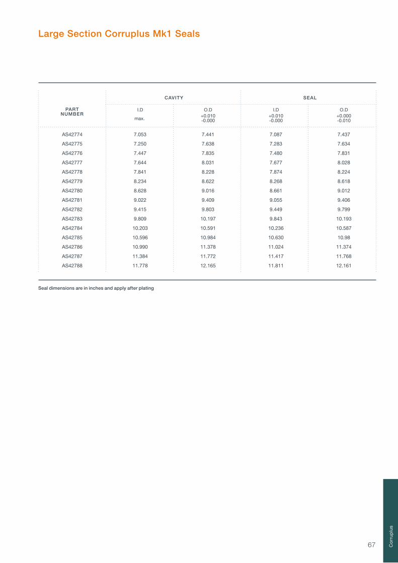
67
PARTNUMBER
max.
Large Section Corruplus Mk1 Seals
CAVITY SEAL
I.D O.D I.D O.D +0.010 +0.010 +0.000 -0.000 -0.000 -0.010
AS42774 7.053 7.441 7.087 7.437
AS42775 7.250 7.638 7.283 7.634
AS42776 7.447 7.835 7.480 7.831
AS42777 7.644 8.031 7.677 8.028
AS42778 7.841 8.228 7.874 8.224
AS42779 8.234 8.622 8.268 8.618
AS42780 8.628 9.016 8.661 9.012
AS42781 9.022 9.409 9.055 9.406
AS42782 9.415 9.803 9.449 9.799
AS42783 9.809 10.197 9.843 10.193
AS42784 10.203 10.591 10.236 10.587
AS42785 10.596 10.984 10.630 10.98
AS42786 10.990 11.378 11.024 11.374
AS42787 11.384 11.772 11.417 11.768
AS42788 11.778 12.165 11.811 12.161
Seal dimensions are in inches and apply after plating
Co
rru
plu
s

68
Corruplus Mk1 Seals For ‘V’ Band Couplings
Corruplus Mk1 for ‘V’ Band Couplings
Corruplus Mk1 Cavity for ‘V’ Band Couplings
Seal I.D
0.010 min.
0.140 min.
0.1200.116
Seal O.D
Seal O.D
Seal O.D
Cavity I.D
0.115 max.
Cavity O.D
This series of CPL/V seals are designed to suit one particular flange configuration as used in the Aircraft Industry
All other Corruplus Mk1 Seals can be used in suitable ‘V’ flanges
CAVITY SEAL
I.D O.D I.D O.D +0.005 +0.010 +0.000 -0.000 -0.000 -0.010
CPL/V 100 0.962 1.364 0.988 1.363
CPL/V 125 1.212 1.614 1.238 1.613
CPL/V 150 1.462 1.864 1.488 1.863
CPL/V 175 1.712 2.114 1.738 2.113
CPL/V 200 1.962 2.364 1.988 2.363
CPL/V 225 2.213 2.615 2.239 2.614
CPL/V 250 2.463 2.865 2.489 2.864
CPL/V 275 2.713 3.115 2.739 3.114
CPL/V 300 2.963 3.365 2.989 3.364
CPL/V 325 3.213 3.615 3.239 3.614
CPL/V 350 3.464 3.866 3.49 3.865
CPL/V 400 3.964 4.366 3.99 4.365
CPL/V 450 4.464 4.866 4.49 4.865
CPL/V 500 4.966 5.368 4.992 5.367
CPL/V 550 5.466 5.868 5.492 5.867
CPL/V 600 5.966 6.368 5.992 6.367
PARTNUMBER
max.
Seal dimensions are in inches and apply after plating
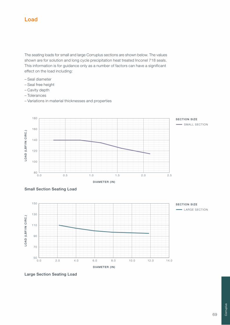
69
Load
The seating loads for small and large Corruplus sections are shown below. The values shown are for solution and long cycle precipitation heat treated Inconel 718 seals.This information is for guidance only as a number of factors can have a significant effect on the load including:
– Seal diameter– Seal free height– Cavity depth– Tolerances– Variations in material thicknesses and properties
SECTION SIZE
0.0 0.5 1.0 1.5 2.0 2.580
100
120
140
160
180
SMALL SECTION
DIAMETER ( IN)
LO
AD
(L
BF
/IN
CIR
C.)
0.0 2.0 4.0 6.0 8.0 10.0 12.0 14.050
70
90
110
130
150
DIAMETER ( IN)
SECTION SIZE
LARGE SECTION
LO
AD
(L
BF
/IN
CIR
C.)
Small Section Seating Load
Large Section Seating Load
Co
rru
plu
s

70

71
Product DescriptionE-Seal SpecificationDiameter Codes (EIS Series)Diameter Codes (EES Series)Diameter Codes (EIL Series)Diameter Codes (EEL Series)Load
E-Seals
72 737680848894

72
EIS Series – Internal Pressure Short Leg
EES Series – External Pressure Short Leg
EIL Series – Internal Pressure Long Leg
EEL Series – External Pressure Long Leg
Product Description
E-Seals are designed to be compressed in a cavity of a controlled depth creating a seal. Short leg and long leg options are available to accommodate both internal and external pressure conditions.
Part Properties
– Able to seal high and low temperatures and pressures– A flexible low load seal with good recovery– A large range of standard industry sizes are available– A range of standard seal sections are available– Non-round seal shapes can be manufactured

73
E-Seal Specification
Nicholsons offer a range of standard E-Seal part numbers. The part number system enables the selection of the correct seal for each application and installation using the permutations of size, material, plating etc. An explanation of the Nicholsons E-Seal part number system is shown below.
We also offer a specialist range of E-Seals which are designed for use in standard aerospace flange and duct systems. Please consult the High Temperature Duct Seals section on page 98 for further details.
Bespoke E-Seals can be designed for specific applications where the use of a standard E-Seal would not be appropriate due to shape, diameter, material type etc. Please contact us if you require a bespoke design or need any assistance specifying a standard E-Seal part number for your application.
1. SEAL TYPEThe type of seal and its orientation
2. DIAMETERThe seal and cavity diameters
3. SECTION AND MATERIAL THICKNESSThe seal section height and the standard material thickness options available for each
4. MATERIAL TYPEThe material type that we offer as standard
5. HEAT TREATMENTThe heat treatments that we offer as standard. Not all heat treatments are applicable to all materials
6. PLATING OR COATINGThe plating or coating type that we offer as standard
7. PLATING OR COATING THICKNESSThe thickness of the plating or coating
XXX 0000 00 00 0 XX X
1. SEAL TYPEThe first section specifies the seal type.EIS – Internal pressure short leg seal.EES – External pressure short leg seal.EIL – Internal pressure long leg seal.EEL – External pressure long leg seal.
PART NUMBER
E-S
eals
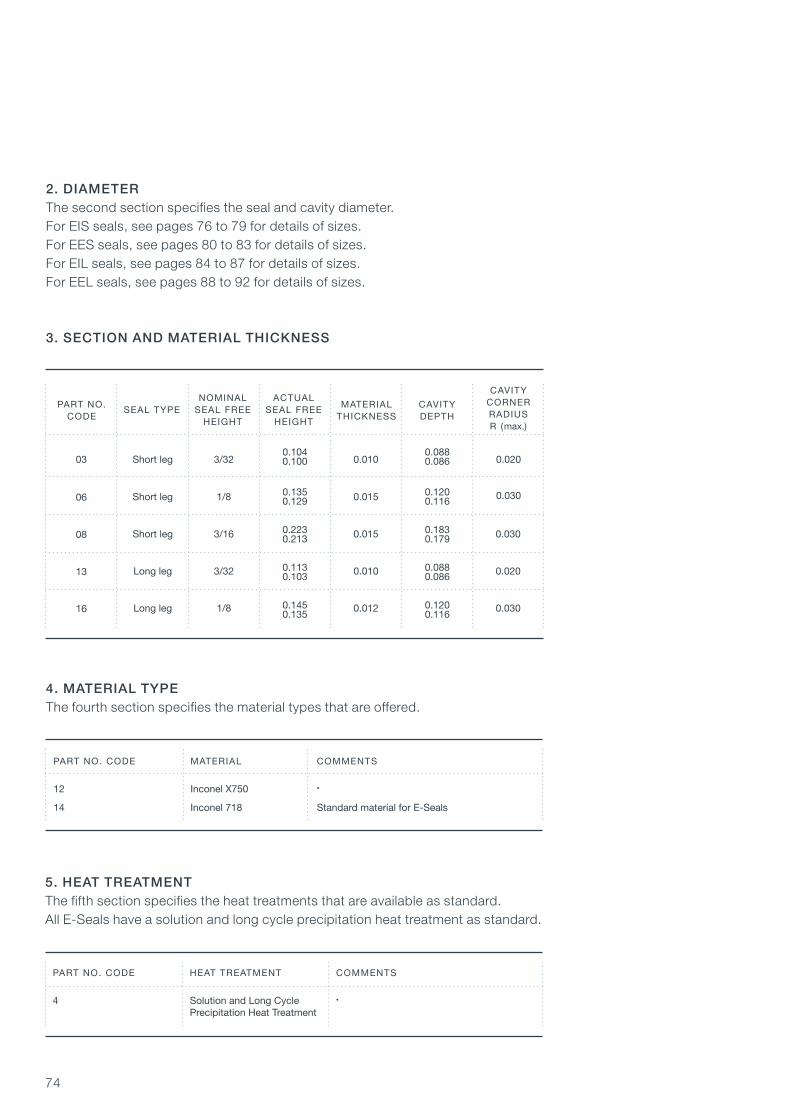
74
4. MATERIAL TYPEThe fourth section specifies the material types that are offered.
PART NO. CODE MATERIAL COMMENTS
12 Inconel X750 •
14 Inconel 718 Standard material for E-Seals
5. HEAT TREATMENTThe fifth section specifies the heat treatments that are available as standard.All E-Seals have a solution and long cycle precipitation heat treatment as standard.
PART NO. CODE HEAT TREATMENT COMMENTS
4 Solution and Long Cycle • Precipitation Heat Treatment
NOMINAL ACTUAL SEAL TYPE SEAL FREE SEAL FREE HEIGHT HEIGHT
3. SECTION AND MATERIAL THICKNESS
PART NO.CODE
CAVITYCORNERRADIUSR (max.)
MATERIALTHICKNESS
CAVITY DEPTH
Short leg 0.0103/3203
06
08
13
16
Short leg 0.0151/8
Short leg 0.015 0.0303/16
Long leg 0.010 0.0203/32
Long leg 0.012 0.0301/8
0.020
0.030
2. DIAMETERThe second section specifies the seal and cavity diameter.For EIS seals, see pages 76 to 79 for details of sizes.For EES seals, see pages 80 to 83 for details of sizes.For EIL seals, see pages 84 to 87 for details of sizes.For EEL seals, see pages 88 to 92 for details of sizes.
0.1040.100
0.0880.086
0.1350.129
0.1200.116
0.2230.213
0.1830.179
0.1130.103
0.0880.086
0.1450.135
0.1200.116

75
PART NO. PLATING OR CODE COATING THICKNESS COMMENTS
A Standard for Silver
B •
C •
D •
E Customer Specification Customer Specification
O None Use with Unplated Seals
6. PLATING OR COATINGThe sixth section specifies the plating or coating applied to the seal. Plating may be incomplete away from sealing surfaces.
PART NO. CODE PLATING OR COATING COMMENTS
OP None •
SP Silver Suitable for most applications
NP Nickel •
CP Copper •
GP Gold Very expensive
LP Lead Soft. Max. temp. 150°C/300°F
PP PTFE Max. temp. 220°C/430°F
IP Indium Very soft. Low temp only
7. PLATING OR COATING THICKNESSThe seventh section specifies the plating or coating thickness.
0.00100.0005
0.00150.0010
0.00250.0015
0.00300.0020
E-S
eals

76
FREE HEIGHT 3/32 FREE HEIGHT 1/8 FREE HEIGHT 3/16
CAVITY SEAL CAVITY SEAL CAVITY SEAL
I.D O.D I.D O.D I.D O.D I.D O.D I.D O.D I.D O.D +0.003 +0.000 +0.003 +0.000 +0.003 +0.000 -0.000 -0.003 -0.000 -0.003 -0.000 -0.003
EIS 0030 1.875 2.062 1.878 2.059 1.875 2.125 1.878 2.122 • • • •
EIS 0031 1.937 2.125 1.940 2.122 1.937 2.187 1.940 2.184 • • • •
EIS 0032 2.000 2.187 2.003 2.184 2.000 2.250 2.003 2.247 • • • •
EIS 0033 2.062 2.250 2.065 2.247 2.062 2.312 2.065 2.309 • • • •
EIS 0034 2.125 2.312 2.128 2.309 2.125 2.375 2.128 2.372 • • • •
EIS 0035 2.187 2.375 2.190 2.372 2.187 2.437 2.190 2.434 • • • •
EIS 0036 2.250 2.437 2.253 2.434 2.250 2.500 2.253 2.497 • • • •
EIS 0037 2.312 2.500 2.315 2.497 2.312 2.562 2.315 2.559 • • • •
EIS 0038 2.375 2.562 2.378 2.559 2.375 2.625 2.378 2.622 • • • •
EIS 0039 2.437 2.625 2.440 2.622 2.437 2.687 2.440 2.684 • • • •
EIS 0040 2.500 2.687 2.503 2.684 2.500 2.750 2.503 2.747 • • • •
EIS 0041 2.562 2.750 2.565 2.747 2.562 2.812 2.565 2.809 • • • •
EIS 0042 2.625 2.812 2.628 2.809 2.625 2.875 2.628 2.872 • • • •
EIS 0043 2.687 2.875 2.690 2.872 2.687 2.937 2.690 2.934 • • • •
EIS 0044 2.750 2.937 2.753 2.934 2.750 3.000 2.753 2.997 • • • •
EIS 0045 2.812 3.000 2.815 2.997 2.812 3.062 2.815 3.059 • • • •
EIS 0046 2.875 3.062 2.878 3.059 2.875 3.125 2.878 3.122 • • • •
EIS 0047 2.937 3.125 2.940 3.122 2.937 3.187 2.940 3.184 • • • •
EIS 0048 3.000 3.187 3.003 3.184 3.000 3.250 3.003 3.247 3.000 3.375 3.003 3.372
EIS 0049 3.062 3.250 3.065 3.247 3.062 3.312 3.065 3.309 3.062 3.437 3.065 3.434
I.D O.D I.D O.D I.D O.D I.D O.D I.D O.D I.D O.D +0.004 +0.000 +0.004 +0.000 +0.004 +0.000 -0.000 -0.004 -0.000 -0.004 -0.000 -0.004
EIS 0050 3.125 3.312 3.128 3.309 3.125 3.375 3.128 3.372 3.125 3.500 3.128 3.497
EIS Series – Internal Pressure Short Leg E-Seal
SEAL TYPE& DIAMETER
max. min. max. min. max. min.
Cavity O.D
Cavity I.D
Seal O.D
R
Seal FreeHeight
Seal I.D
Internal E-Seal Cavity
Seal dimensions are in inches and are prior to plating or coating
max. min. max. min. max. min.
– Weld permitted
– Plating may be incomplete away from sealing surfaces
– Seal diameters are an average and can be out of round in excess of tolerances
– See the E-Seal introduction pages for details of seal free height, cavity depth and radius R
CavityDepth

77 E-S
eals
FREE HEIGHT 3/32 FREE HEIGHT 1/8 FREE HEIGHT 3/16
CAVITY SEAL CAVITY SEAL CAVITY SEAL
I.D O.D I.D O.D I.D O.D I.D O.D I.D O.D I.D O.D +0.004 +0.000 +0.004 +0.000 +0.004 +0.000 -0.000 -0.004 -0.000 -0.004 -0.000 -0.004
SEAL TYPE& DIAMETER
max. min. max. min. max. min.
Seal dimensions are in inches and are prior to plating or coating
EIS 0051 3.187 3.375 3.190 3.372 3.187 3.437 3.190 3.434 3.187 3.562 3.190 3.559
EIS 0052 3.250 3.437 3.253 3.434 3.250 3.500 3.253 3.497 3.250 3.625 3.253 3.622
EIS 0053 3.312 3.500 3.315 3.497 3.312 3.562 3.315 3.559 3.312 3.687 3.315 3.684
EIS 0054 3.375 3.562 3.378 3.559 3.375 3.625 3.378 3.622 3.375 3.750 3.378 3.747
EIS 0055 3.437 3.625 3.440 3.622 3.437 3.687 3.440 3.684 3.437 3.812 3.440 3.809
EIS 0056 3.500 3.687 3.503 3.684 3.500 3.750 3.503 3.747 3.500 3.875 3.503 3.872
EIS 0057 3.562 3.750 3.565 3.747 3.562 3.812 3.565 3.809 3.562 3.937 3.565 3.934
EIS 0058 3.625 3.812 3.628 3.809 3.625 3.875 3.628 3.872 3.625 4.000 3.628 3.997
EIS 0059 3.687 3.875 3.690 3.872 3.687 3.937 3.690 3.934 3.687 4.062 3.690 4.059
EIS 0060 3.750 3.937 3.753 3.934 3.750 4.000 3.753 3.997 3.750 4.125 3.753 4.122
EIS 0061 3.812 4.000 3.815 3.997 3.812 4.062 3.815 4.059 3.812 4.187 3.815 4.184
EIS 0062 3.875 4.062 3.878 4.059 3.875 4.125 3.878 4.122 3.875 4.250 3.878 4.247
EIS 0063 3.937 4.125 3.940 4.122 3.937 4.187 3.940 4.184 3.937 4.312 3.940 4.309
EIS 0064 4.000 4.187 4.003 4.184 4.000 4.250 4.003 4.247 4.000 4.375 4.003 4.372
EIS 0065 4.062 4.250 4.065 4.247 4.062 4.312 4.065 4.309 4.062 4.437 4.065 4.434
EIS 0066 4.125 4.312 4.128 4.309 4.125 4.375 4.128 4.372 4.125 4.500 4.128 4.497
EIS 0067 4.187 4.375 4.190 4.372 4.187 4.437 4.190 4.434 4.187 4.562 4.190 4.559
EIS 0068 4.250 4.437 4.253 4.434 4.250 4.500 4.253 4.497 4.250 4.625 4.253 4.622
EIS 0069 4.312 4.500 4.315 4.497 4.312 4.562 4.315 4.559 4.312 4.687 4.315 4.684
EIS 0070 4.375 4.562 4.378 4.559 4.375 4.625 4.378 4.622 4.375 4.750 4.378 4.747
EIS 0071 4.437 4.625 4.440 4.622 4.437 4.687 4.440 4.684 4.437 4.812 4.440 4.809
EIS 0072 4.500 4.687 4.503 4.684 4.500 4.750 4.503 4.747 4.500 4.875 4.503 4.872
EIS 0073 4.562 4.750 4.565 4.747 4.562 4.812 4.565 4.809 4.562 4.937 4.565 4.934
EIS 0074 4.625 4.812 4.628 4.809 4.625 4.875 4.628 4.872 4.625 5.000 4.628 4.997
EIS 0075 4.687 4.875 4.690 4.872 4.687 4.937 4.690 4.934 4.687 5.062 4.690 5.059
EIS 0076 4.750 4.937 4.753 4.934 4.750 5.000 4.753 4.997 4.750 5.125 4.753 5.122
EIS 0077 4.812 5.000 4.815 4.997 4.812 5.062 4.815 5.059 4.812 5.187 4.815 5.184
EIS 0078 4.875 5.062 4.878 5.059 4.875 5.125 4.878 5.122 4.875 5.250 4.878 5.247
EIS 0079 4.937 5.125 4.940 5.122 4.937 5.187 4.940 5.184 4.937 5.312 4.940 5.309
EIS 0080 5.000 5.187 5.003 5.184 5.000 5.250 5.003 5.247 5.000 5.375 5.003 5.372
EIS 0081 5.062 5.250 5.065 5.247 5.062 5.312 5.065 5.309 5.062 5.347 5.065 5.434
I.D O.D I.D O.D I.D O.D I.D O.D I.D O.D I.D O.D +0.006 +0.000 +0.006 +0.000 +0.006 +0.000 -0.000 -0.006 -0.000 -0.006 -0.000 -0.006
EIS 0082 5.125 5.312 5.128 5.309 5.125 5.375 5.128 5.372 5.125 5.500 5.128 5.497
EIS 0083 5.187 5.375 5.190 5.372 5.187 5.437 5.190 5.434 5.187 5.562 5.190 5.559
EIS 0084 5.250 5.437 5.253 5.434 5.250 5.500 5.253 5.497 5.250 5.625 5.253 5.622
EIS 0085 5.312 5.500 5.315 5.497 5.312 5.562 5.315 5.559 5.312 5.687 5.315 5.684
EIS 0086 5.375 5.562 5.378 5.559 5.375 5.625 5.378 5.622 5.375 5.750 5.378 5.747
max. min. max. min. max. min.
EIS Series – Internal Pressure Short Leg E-Seal
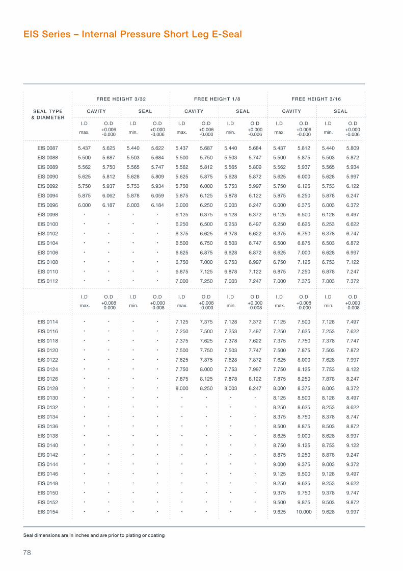
78
FREE HEIGHT 3/32 FREE HEIGHT 1/8 FREE HEIGHT 3/16
CAVITY SEAL CAVITY SEAL CAVITY SEAL
I.D O.D I.D O.D I.D O.D I.D O.D I.D O.D I.D O.D +0.006 +0.000 +0.006 +0.000 +0.006 +0.000 -0.000 -0.006 -0.000 -0.006 -0.000 -0.006
SEAL TYPE& DIAMETER
max. min. max. min. max. min.
Seal dimensions are in inches and are prior to plating or coating
EIS 0087 5.437 5.625 5.440 5.622 5.437 5.687 5.440 5.684 5.437 5.812 5.440 5.809
EIS 0088 5.500 5.687 5.503 5.684 5.500 5.750 5.503 5.747 5.500 5.875 5.503 5.872
EIS 0089 5.562 5.750 5.565 5.747 5.562 5.812 5.565 5.809 5.562 5.937 5.565 5.934
EIS 0090 5.625 5.812 5.628 5.809 5.625 5.875 5.628 5.872 5.625 6.000 5.628 5.997
EIS 0092 5.750 5.937 5.753 5.934 5.750 6.000 5.753 5.997 5.750 6.125 5.753 6.122
EIS 0094 5.875 6.062 5.878 6.059 5.875 6.125 5.878 6.122 5.875 6.250 5.878 6.247
EIS 0096 6.000 6.187 6.003 6.184 6.000 6.250 6.003 6.247 6.000 6.375 6.003 6.372
EIS 0098 • • • • 6.125 6.375 6.128 6.372 6.125 6.500 6.128 6.497
EIS 0100 • • • • 6.250 6.500 6.253 6.497 6.250 6.625 6.253 6.622
EIS 0102 • • • • 6.375 6.625 6.378 6.622 6.375 6.750 6.378 6.747
EIS 0104 • • • • 6.500 6.750 6.503 6.747 6.500 6.875 6.503 6.872
EIS 0106 • • • • 6.625 6.875 6.628 6.872 6.625 7.000 6.628 6.997
EIS 0108 • • • • 6.750 7.000 6.753 6.997 6.750 7.125 6.753 7.122
EIS 0110 • • • • 6.875 7.125 6.878 7.122 6.875 7.250 6.878 7.247
EIS 0112 • • • • 7.000 7.250 7.003 7.247 7.000 7.375 7.003 7.372
I.D O.D I.D O.D I.D O.D I.D O.D I.D O.D I.D O.D +0.008 +0.000 +0.008 +0.000 +0.008 +0.000 -0.000 -0.008 -0.000 -0.008 -0.000 -0.008
EIS 0114 • • • • 7.125 7.375 7.128 7.372 7.125 7.500 7.128 7.497
EIS 0116 • • • • 7.250 7.500 7.253 7.497 7.250 7.625 7.253 7.622
EIS 0118 • • • • 7.375 7.625 7.378 7.622 7.375 7.750 7.378 7.747
EIS 0120 • • • • 7.500 7.750 7.503 7.747 7.500 7.875 7.503 7.872
EIS 0122 • • • • 7.625 7.875 7.628 7.872 7.625 8.000 7.628 7.997
EIS 0124 • • • • 7.750 8.000 7.753 7.997 7.750 8.125 7.753 8.122
EIS 0126 • • • • 7.875 8.125 7.878 8.122 7.875 8.250 7.878 8.247
EIS 0128 • • • • 8.000 8.250 8.003 8.247 8.000 8.375 8.003 8.372
EIS 0130 • • • • • • • • 8.125 8.500 8.128 8.497
EIS 0132 • • • • • • • • 8.250 8.625 8.253 8.622
EIS 0134 • • • • • • • • 8.375 8.750 8.378 8.747
EIS 0136 • • • • • • • • 8.500 8.875 8.503 8.872
EIS 0138 • • • • • • • • 8.625 9.000 8.628 8.997
EIS 0140 • • • • • • • • 8.750 9.125 8.753 9.122
EIS 0142 • • • • • • • • 8.875 9.250 8.878 9.247
EIS 0144 • • • • • • • • 9.000 9.375 9.003 9.372
EIS 0146 • • • • • • • • 9.125 9.500 9.128 9.497
EIS 0148 • • • • • • • • 9.250 9.625 9.253 9.622
EIS 0150 • • • • • • • • 9.375 9.750 9.378 9.747
EIS 0152 • • • • • • • • 9.500 9.875 9.503 9.872
EIS 0154 • • • • • • • • 9.625 10.000 9.628 9.997
max. min. max. min. max. min.
EIS Series – Internal Pressure Short Leg E-Seal

79 E-S
eals
FREE HEIGHT 3/32 FREE HEIGHT 1/8 FREE HEIGHT 3/16
CAVITY SEAL CAVITY SEAL CAVITY SEAL
I.D O.D I.D O.D I.D O.D I.D O.D I.D O.D I.D O.D +0.008 +0.000 +0.008 +0.000 +0.008 +0.000 -0.000 -0.008 -0.000 -0.008 -0.000 -0.008
SEAL TYPE& DIAMETER
max. min. max. min. max. min.
Seal dimensions are in inches and are prior to plating or coating
EIS 0156 • • • • • • • • 9.750 10.125 9.753 10.122
EIS 0158 • • • • • • • • 9.875 10.250 9.878 10.247
EIS 0160 • • • • • • • • 10.000 10.375 10.003 10.372
I.D O.D I.D O.D I.D O.D I.D O.D I.D O.D I.D O.D +0.012 +0.000 +0.012 +0.000 +0.012 +0.000 -0.000 -0.012 -0.000 -0.012 -0.000 -0.012
EIS 0162 • • • • • • • • 10.125 10.500 10.128 10.497
EIS 0164 • • • • • • • • 10.250 10.625 10.253 10.622
EIS 0166 • • • • • • • • 10.375 10.750 10.378 10.747
EIS 0168 • • • • • • • • 10.500 10.875 10.503 10.872
EIS 0170 • • • • • • • • 10.625 11.000 10.628 10.997
EIS 0172 • • • • • • • • 10.750 11.125 10.753 11.122
EIS 0174 • • • • • • • • 10.875 11.250 10.878 11.247
EIS 0176 • • • • • • • • 11.000 11.375 11.003 11.372
EIS 0178 • • • • • • • • 11.125 11.500 11.128 11.497
EIS 0180 • • • • • • • • 11.250 11.625 11.253 11.622
EIS 0182 • • • • • • • • 11.375 11.750 11.378 11.747
EIS 0184 • • • • • • • • 11.500 11.875 11.503 11.872
EIS 0186 • • • • • • • • 11.625 12.000 11.628 11.997
EIS 0188 • • • • • • • • 11.750 12.125 11.753 12.122
EIS 0190 • • • • • • • • 11.875 12.250 11.878 12.247
EIS 0192 • • • • • • • • 12.000 12.375 12.003 12.372
EIS 0194 • • • • • • • • 12.125 12.500 12.128 12.497
EIS 0196 • • • • • • • • 12.250 12.625 12.253 12.622
EIS 0198 • • • • • • • • 12.375 12.750 12.378 12.747
max. min. max. min. max. min.
EIS Series – Internal Pressure Short Leg E-Seal

80
FREE HEIGHT 3/32 FREE HEIGHT 1/8 FREE HEIGHT 3/16
CAVITY SEAL CAVITY SEAL CAVITY SEAL
I.D O.D I.D O.D I.D O.D I.D O.D I.D O.D I.D O.D +0.000 +0.003 +0.000 +0.003 +0.000 +0.003 -0.003 -0.000 -0.003 -0.000 -0.003 -0.000
EES 0030 1.875 2.062 1.878 2.059 1.875 2.125 1.878 2.122 • • • •
EES 0031 1.937 2.125 1.940 2.122 1.937 2.187 1.940 2.184 • • • •
EES 0032 2.000 2.187 2.003 2.184 2.000 2.250 2.003 2.247 • • • •
EES 0033 2.062 2.250 2.065 2.247 2.062 2.312 2.065 2.309 • • • •
EES 0034 2.125 2.312 2.128 2.309 2.125 2.375 2.128 2.372 • • • •
EES 0035 2.187 2.375 2.190 2.372 2.187 2.437 2.190 2.434 • • • •
EES 0036 2.250 2.437 2.253 2.434 2.250 2.500 2.253 2.497 • • • •
EES 0037 2.312 2.500 2.315 2.497 2.312 2.562 2.315 2.559 • • • •
EES 0038 2.375 2.562 2.378 2.559 2.375 2.625 2.378 2.622 • • • •
EES 0039 2.437 2.625 2.440 2.622 2.437 2.687 2.440 2.684 • • • •
EES 0040 2.500 2.687 2.503 2.684 2.500 2.750 2.503 2.747 • • • •
EES 0041 2.562 2.750 2.565 2.747 2.562 2.812 2.565 2.809 • • • •
EES 0042 2.625 2.812 2.628 2.809 2.625 2.875 2.628 2.872 • • • •
EES 0043 2.687 2.875 2.690 2.872 2.687 2.937 2.690 2.934 • • • •
EES 0044 2.750 2.937 2.753 2.934 2.750 3.000 2.753 2.997 • • • •
EES 0045 2.812 3.000 2.815 2.997 2.812 3.062 2.815 3.059 • • • •
EES 0046 2.875 3.062 2.878 3.059 2.875 3.125 2.878 3.122 • • • •
EES 0047 2.937 3.125 2.940 3.122 2.937 3.187 2.940 3.184 • • • •
EES 0048 3.000 3.187 3.003 3.184 3.000 3.250 3.003 3.247 3.000 3.375 3.003 3.372
I.D O.D I.D O.D I.D O.D I.D O.D I.D O.D I.D O.D +0.000 +0.004 +0.000 +0.004 +0.000 +0.004 -0.004 -0.000 -0.004 -0.000 -0.004 -0.000
EES 0049 3.062 3.250 3.065 3.247 3.062 3.312 3.065 3.309 3.062 3.437 3.065 3.434
SEAL TYPE& DIAMETER
min. max. min. max. min. max.
Cavity O.D
Cavity I.D
Seal O.D
R
Seal FreeHeight
Seal I.D
Seal dimensions are in inches and are prior to plating or coating
min. max. min. max. min. max.
EES Series – External Pressure Short Leg E-Seal
External E-Seal Cavity
– Weld permitted
– Plating may be incomplete away from sealing surfaces
– Seal diameters are an average and can be out of round in excess of tolerances
– See the E-Seal introduction pages for details of seal free height, cavity depth and radius R
CavityDepth
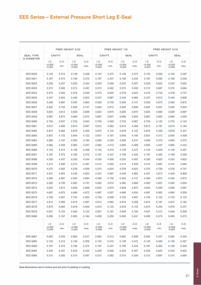
81 E-S
eals
FREE HEIGHT 3/32 FREE HEIGHT 1/8 FREE HEIGHT 3/16
CAVITY SEAL CAVITY SEAL CAVITY SEAL
I.D O.D I.D O.D I.D O.D I.D O.D I.D O.D I.D O.D +0.000 +0.004 +0.000 +0.004 +0.000 +0.004 -0.004 -0.000 -0.004 -0.000 -0.004 -0.000
SEAL TYPE& DIAMETER
Seal dimensions are in inches and are prior to plating or coating
EES 0050 3.125 3.312 3.128 3.309 3.125 3.375 3.128 3.372 3.125 3.500 3.128 3.497
EES 0051 3.187 3.375 3.190 3.372 3.187 3.437 3.190 3.434 3.187 3.562 3.190 3.559
EES 0052 3.250 3.437 3.253 3.434 3.250 3.500 3.253 3.497 3.250 3.625 3.253 3.622
EES 0053 3.312 3.500 3.315 3.497 3.312 3.562 3.315 3.559 3.312 3.687 3.315 3.684
EES 0054 3.375 3.562 3.378 3.559 3.375 3.625 3.378 3.622 3.375 3.750 3.378 3.747
EES 0055 3.437 3.625 3.440 3.622 3.437 3.687 3.440 3.684 3.437 3.812 3.440 3.809
EES 0056 3.500 3.687 3.503 3.684 3.500 3.750 3.503 3.747 3.500 3.875 3.503 3.872
EES 0057 3.562 3.750 3.565 3.747 3.562 3.812 3.565 3.809 3.562 3.937 3.565 3.934
EES 0058 3.625 3.812 3.628 3.809 3.625 3.875 3.628 3.872 3.625 4.000 3.628 3.997
EES 0059 3.687 3.875 3.690 3.872 3.687 3.937 3.690 3.934 3.687 4.062 3.690 4.059
EES 0060 3.750 3.937 3.753 3.934 3.750 4.000 3.753 3.997 3.750 4.125 3.753 4.122
EES 0061 3.812 4.000 3.815 3.997 3.812 4.062 3.815 4.059 3.812 4.187 3.815 4.184
EES 0062 3.875 4.062 3.878 4.059 3.875 4.125 3.878 4.122 3.875 4.250 3.878 4.247
EES 0063 3.937 4.125 3.940 4.122 3.937 4.187 3.940 4.184 3.937 4.312 3.940 4.309
EES 0064 4.000 4.187 4.003 4.184 4.000 4.250 4.003 4.247 4.000 4.375 4.003 4.372
EES 0065 4.062 4.250 4.065 4.247 4.062 4.312 4.065 4.309 4.062 4.437 4.065 4.434
EES 0066 4.125 4.312 4.128 4.309 4.125 4.375 4.128 4.372 4.125 4.500 4.128 4.497
EES 0067 4.187 4.375 4.190 4.372 4.187 4.437 4.190 4.434 4.187 4.562 4.190 4.559
EES 0068 4.250 4.437 4.253 4.434 4.250 4.500 4.253 4.497 4.250 4.625 4.253 4.622
EES 0069 4.312 4.500 4.315 4.497 4.312 4.562 4.315 4.559 4.312 4.687 4.315 4.684
EES 0070 4.375 4.562 4.378 4.559 4.375 4.625 4.378 4.622 4.375 4.750 4.378 4.747
EES 0071 4.437 4.625 4.440 4.622 4.437 4.687 4.440 4.684 4.437 4.812 4.440 4.809
EES 0072 4.500 4.687 4.503 4.684 4.500 4.750 4.503 4.747 4.500 4.875 4.503 4.872
EES 0073 4.562 4.750 4.565 4.747 4.562 4.812 4.565 4.809 4.562 4.937 4.565 4.934
EES 0074 4.625 4.812 4.628 4.809 4.625 4.875 4.628 4.872 4.625 5.000 4.628 4.997
EES 0075 4.687 4.875 4.690 4.872 4.687 4.937 4.690 4.934 4.687 5.062 4.690 5.059
EES 0076 4.750 4.937 4.753 4.934 4.750 5.000 4.753 4.997 4.750 5.125 4.753 5.122
EES 0077 4.812 5.000 4.815 4.997 4.812 5.062 4.815 5.059 4.812 5.187 4.815 5.184
EES 0078 4.875 5.062 4.878 5.059 4.875 5.125 4.878 5.122 4.875 5.250 4.878 5.247
EES 0079 4.937 5.125 4.940 5.122 4.937 5.187 4.940 5.184 4.937 5.312 4.940 5.309
EES 0080 5.000 5.187 5.003 5.184 5.000 5.250 5.003 5.247 5.000 5.375 5.003 5.372
I.D O.D I.D O.D I.D O.D I.D O.D I.D O.D I.D O.D +0.000 +0.006 +0.000 +0.006 +0.000 +0.006 -0.006 -0.000 -0.006 -0.000 -0.006 -0.000
EES 0081 5.062 5.250 5.065 5.247 5.062 5.312 5.065 5.309 5.062 5.437 5.065 5.434
EES 0082 5.125 5.312 5.128 5.309 5.125 5.375 5.128 5.372 5.125 5.500 5.128 5.497
EES 0083 5.187 5.375 5.190 5.372 5.187 5.437 5.190 5.434 5.187 5.562 5.190 5.559
EES 0084 5.250 5.437 5.253 5.434 5.250 5.500 5.253 5.497 5.250 5.625 5.253 5.622
EES 0085 5.312 5.500 5.315 5.497 5.312 5.562 5.315 5.559 5.312 5.687 5.315 5.684
min. max. min. max. min. max.
min. max. min. max. min. max.
EES Series – External Pressure Short Leg E-Seal
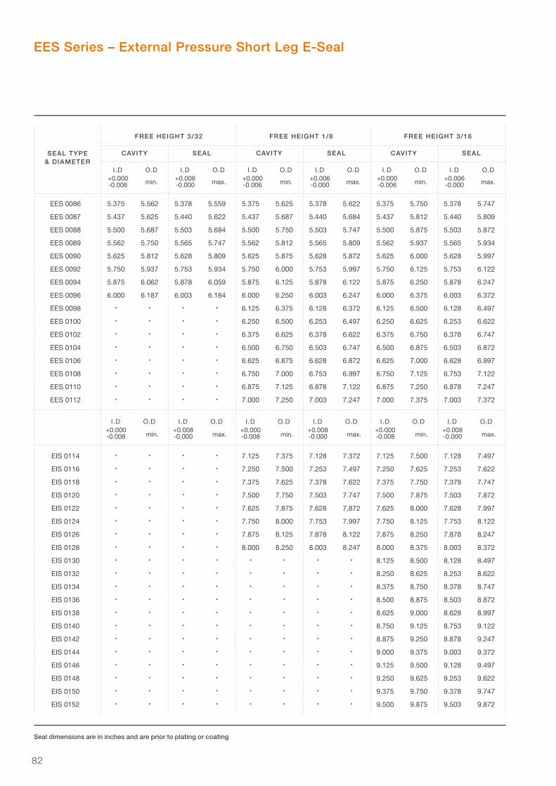
82
FREE HEIGHT 3/32 FREE HEIGHT 1/8 FREE HEIGHT 3/16
CAVITY SEAL CAVITY SEAL CAVITY SEAL
I.D O.D I.D O.D I.D O.D I.D O.D I.D O.D I.D O.D +0.000 +0.006 +0.000 +0.006 +0.000 +0.006 -0.006 -0.000 -0.006 -0.000 -0.006 -0.000
SEAL TYPE& DIAMETER
Seal dimensions are in inches and are prior to plating or coating
EES 0086 5.375 5.562 5.378 5.559 5.375 5.625 5.378 5.622 5.375 5.750 5.378 5.747
EES 0087 5.437 5.625 5.440 5.622 5.437 5.687 5.440 5.684 5.437 5.812 5.440 5.809
EES 0088 5.500 5.687 5.503 5.684 5.500 5.750 5.503 5.747 5.500 5.875 5.503 5.872
EES 0089 5.562 5.750 5.565 5.747 5.562 5.812 5.565 5.809 5.562 5.937 5.565 5.934
EES 0090 5.625 5.812 5.628 5.809 5.625 5.875 5.628 5.872 5.625 6.000 5.628 5.997
EES 0092 5.750 5.937 5.753 5.934 5.750 6.000 5.753 5.997 5.750 6.125 5.753 6.122
EES 0094 5.875 6.062 5.878 6.059 5.875 6.125 5.878 6.122 5.875 6.250 5.878 6.247
EES 0096 6.000 6.187 6.003 6.184 6.000 6.250 6.003 6.247 6.000 6.375 6.003 6.372
EES 0098 • • • • 6.125 6.375 6.128 6.372 6.125 6.500 6.128 6.497
EES 0100 • • • • 6.250 6.500 6.253 6.497 6.250 6.625 6.253 6.622
EES 0102 • • • • 6.375 6.625 6.378 6.622 6.375 6.750 6.378 6.747
EES 0104 • • • • 6.500 6.750 6.503 6.747 6.500 6.875 6.503 6.872
EES 0106 • • • • 6.625 6.875 6.628 6.872 6.625 7.000 6.628 6.997
EES 0108 • • • • 6.750 7.000 6.753 6.997 6.750 7.125 6.753 7.122
EES 0110 • • • • 6.875 7.125 6.878 7.122 6.875 7.250 6.878 7.247
EES 0112 • • • • 7.000 7.250 7.003 7.247 7.000 7.375 7.003 7.372
I.D O.D I.D O.D I.D O.D I.D O.D I.D O.D I.D O.D +0.000 +0.008 +0.000 +0.008 +0.000 +0.008 -0.008 -0.000 -0.008 -0.000 -0.008 -0.000
EIS 0114 • • • • 7.125 7.375 7.128 7.372 7.125 7.500 7.128 7.497
EIS 0116 • • • • 7.250 7.500 7.253 7.497 7.250 7.625 7.253 7.622
EIS 0118 • • • • 7.375 7.625 7.378 7.622 7.375 7.750 7.378 7.747
EIS 0120 • • • • 7.500 7.750 7.503 7.747 7.500 7.875 7.503 7.872
EIS 0122 • • • • 7.625 7.875 7.628 7.872 7.625 8.000 7.628 7.997
EIS 0124 • • • • 7.750 8.000 7.753 7.997 7.750 8.125 7.753 8.122
EIS 0126 • • • • 7.875 8.125 7.878 8.122 7.875 8.250 7.878 8.247
EIS 0128 • • • • 8.000 8.250 8.003 8.247 8.000 8.375 8.003 8.372
EIS 0130 • • • • • • • • 8.125 8.500 8.128 8.497
EIS 0132 • • • • • • • • 8.250 8.625 8.253 8.622
EIS 0134 • • • • • • • • 8.375 8.750 8.378 8.747
EIS 0136 • • • • • • • • 8.500 8.875 8.503 8.872
EIS 0138 • • • • • • • • 8.625 9.000 8.628 8.997
EIS 0140 • • • • • • • • 8.750 9.125 8.753 9.122
EIS 0142 • • • • • • • • 8.875 9.250 8.878 9.247
EIS 0144 • • • • • • • • 9.000 9.375 9.003 9.372
EIS 0146 • • • • • • • • 9.125 9.500 9.128 9.497
EIS 0148 • • • • • • • • 9.250 9.625 9.253 9.622
EIS 0150 • • • • • • • • 9.375 9.750 9.378 9.747
EIS 0152 • • • • • • • • 9.500 9.875 9.503 9.872
min. max. min. max. min. max.
min. max. min. max. min. max.
EES Series – External Pressure Short Leg E-Seal

83 E-S
eals
FREE HEIGHT 3/32 FREE HEIGHT 1/8 FREE HEIGHT 3/16
CAVITY SEAL CAVITY SEAL CAVITY SEAL
I.D O.D I.D O.D I.D O.D I.D O.D I.D O.D I.D O.D +0.000 +0.008 +0.000 +0.008 +0.000 +0.008 -0.008 -0.000 -0.008 -0.000 -0.008 -0.000
SEAL TYPE& DIAMETER
Seal dimensions are in inches and are prior to plating or coating
EIS 0154 • • • • • • • • 9.625 10.000 9.628 9.997
EIS 0156 • • • • • • • • 9.750 10.125 9.753 10.122
EIS 0158 • • • • • • • • 9.875 10.250 9.878 10.247
EIS 0160 • • • • • • • • 10.000 10.375 10.003 10.372
I.D O.D I.D O.D I.D O.D I.D O.D I.D O.D I.D O.D +0.000 +0.012 +0.000 +0.012 +0.000 +0.012 -0.012 -0.000 -0.012 -0.000 -0.012 -0.000
EES 0162 • • • • • • • • 10.125 10.500 10.128 10.497
EES 0164 • • • • • • • • 10.250 10.625 10.253 10.622
EES 0166 • • • • • • • • 10.375 10.750 10.378 10.747
EES 0168 • • • • • • • • 10.500 10.875 10.503 10.872
EES 0170 • • • • • • • • 10.625 11.000 10.628 10.997
EES 0172 • • • • • • • • 10.750 11.125 10.753 11.122
EES 0174 • • • • • • • • 10.875 11.250 10.878 11.247
EES 0176 • • • • • • • • 11.000 11.375 11.003 11.372
EES 0178 • • • • • • • • 11.125 11.500 11.128 11.497
EES 0180 • • • • • • • • 11.250 11.625 11.253 11.622
EES 0182 • • • • • • • • 11.375 11.750 11.378 11.747
EES 0184 • • • • • • • • 11.500 11.875 11.503 11.872
EES 0186 • • • • • • • • 11.625 12.000 11.628 11.997
EES 0188 • • • • • • • • 11.750 12.125 11.753 12.122
EES 0190 • • • • • • • • 11.875 12.250 11.878 12.247
EES 0192 • • • • • • • • 12.000 12.375 12.003 12.372
min. max. min. max. min. max.
min. max. min. max. min. max.
EES Series – External Pressure Short Leg E-Seal

84
SEAL TYPE& DIAMETER
FREE HEIGHT 3/32 FREE HEIGHT 1/8
CAVITY SEAL CAVITY SEAL
I.D O.D I.D O.D I.D O.D I.D O.D +0.003 +0.000 +0.003 +0.000 -0.000 -0.006 -0.000 -0.006
EIL 0033 2.062 2.372 2.076 2.367 2.062 2.469 2.076 2.464
EIL 0034 2.125 2.435 2.139 2.430 2.125 2.532 2.139 2.527
EIL 0035 2.187 2.497 2.201 2.492 2.187 2.594 2.201 2.589
EIL 4261 2.212 2.522 2.226 2.517 2.212 2.619 2.226 2.614
EIL 0036 2.250 2.560 2.264 2.555 2.250 2.657 2.264 2.652
EIL 0037 2.312 2.622 2.326 2.617 2.312 2.719 2.326 2.714
EIL 0038 2.375 2.685 2.389 2.680 2.375 2.782 2.389 2.777
EIL 0039 2.437 2.747 2.451 2.742 2.437 2.844 2.451 2.839
EIL 3274 2.444 2.754 2.458 2.749 2.444 2.851 2.458 2.846
EIL 4286 2.462 2.772 2.476 2.767 2.462 2.869 2.476 2.864
EIL 0040 2.500 2.810 2.514 2.805 2.500 2.907 2.514 2.902
EIL 0041 2.562 2.872 2.576 2.867 2.562 2.969 2.576 2.964
EIL 0042 2.625 2.935 2.639 2.930 2.625 3.032 2.639 3.027
EIL 0043 2.687 2.997 2.701 2.992 2.687 3.094 2.701 3.089
EIL 4311 2.712 3.022 2.726 3.017 2.712 3.119 2.726 3.114
EIL 0044 2.750 3.060 2.764 3.055 2.750 3.157 2.764 3.152
EIL 0045 2.812 3.122 2.826 3.117 2.812 3.219 2.826 3.214
EIL 0046 2.875 3.185 2.889 3.180 2.875 3.282 2.889 3.277
EIL 0047 2.937 3.247 2.951 3.242 2.937 3.344 2.951 3.339
EIL 4336 2.962 3.272 2.976 3.267 2.962 3.369 2.976 3.364
EIL 0048 3.000 3.312 3.016 3.307 3.000 3.409 3.016 3.404
EIL 0049 3.062 3.374 3.078 3.369 3.062 3.471 3.078 3.466
EIL 0050 3.125 3.437 3.141 3.432 3.125 3.534 3.141 3.529
max. min. max. min.
Cavity O.D
Cavity I.D
Seal O.D
R
Seal FreeHeight
Seal I.D
Seal dimensions are in inches and are prior to plating or coating
EIL Series – Internal Pressure Long Leg E-Seal
Internal E-Seal Cavity
– Weld permitted
– Plating may be incomplete away from sealing surfaces
– Seals are manufactured to an average diameter then made to be a snap fit in their cavities. Therefore seal diameters are out of round in excess of tolerances
– See the E-Seal introduction pages for details of seal free height, cavity depth and radius R
CavityDepth

85 E-S
eals
FREE HEIGHT 3/32 FREE HEIGHT 1/8
CAVITY SEAL CAVITY SEAL
I.D O.D I.D O.D I.D O.D I.D O.D +0.004 +0.000 +0.004 +0.000 -0.000 -0.008 -0.000 -0.008
EIL 0051 3.187 3.499 3.203 3.494 3.187 3.596 3.203 3.591
EIL 4361 3.210 3.522 3.226 3.517 3.210 3.619 3.226 3.614
EIL 0052 3.250 3.562 3.266 3.557 3.250 3.659 3.266 3.654
EIL 0053 3.312 3.624 3.328 3.619 3.312 3.721 3.328 3.716
EIL 0054 3.375 3.687 3.391 3.682 3.375 3.784 3.391 3.779
EIL 0055 3.437 3.749 3.453 3.744 3.437 3.846 3.453 3.841
EIL 4386 3.461 3.773 3.477 3.768 3.461 3.870 3.477 3.865
EIL 0056 3.500 3.812 3.516 3.807 3.500 3.909 3.516 3.904
EIL 3386 3.558 3.870 3.574 3.865 3.558 3.967 3.574 3.962
EIL 0057 3.562 3.874 3.578 3.869 3.562 3.971 3.578 3.966
EIL 0058 3.625 3.937 3.641 3.932 3.625 4.034 3.641 4.029
EIL 0059 3.687 3.999 3.703 3.994 3.687 4.096 3.703 4.091
EIL 0060 3.750 4.062 3.766 4.057 3.750 4.159 3.766 4.154
EIL 0061 3.812 4.124 3.828 4.119 3.812 4.221 3.828 4.216
EIL 0062 3.875 4.187 3.891 4.182 3.875 4.284 3.891 4.279
EIL 0063 3.937 4.249 3.953 4.244 3.937 4.346 3.953 4.341
EIL 4436 3.961 4.273 3.977 4.268 3.961 4.370 3.977 4.365
EIL 0064 4.000 4.314 4.018 4.309 4.000 4.411 4.018 4.406
EIL 0065 4.062 4.376 4.080 4.371 4.062 4.473 4.080 4.468
I.D O.D I.D O.D I.D O.D I.D O.D +0.005 +0.000 +0.005 +0.000 -0.000 -0.010 -0.000 -0.010
EIL 0066 4.125 4.439 4.143 4.434 4.125 4.536 4.143 4.531
EIL 0067 4.187 4.501 4.205 4.496 4.187 4.598 4.205 4.593
EIL 0068 4.250 4.564 4.268 4.559 4.250 4.661 4.268 4.656
EIL 0069 4.312 4.626 4.330 4.621 4.312 4.723 4.330 4.718
EIL 0070 4.375 4.689 4.393 4.684 4.375 4.786 4.393 4.781
EIL 0071 4.437 4.751 4.455 4.746 4.437 4.848 4.455 4.843
EIL 4486 4.459 4.773 4.477 4.768 4.459 4.870 4.477 4.865
EIL 0072 4.500 4.814 4.518 4.809 4.500 4.911 4.518 4.906
EIL 0073 4.562 4.876 4.580 4.871 4.562 4.973 4.580 4.968
EIL 0074 4.625 4.939 4.643 4.934 4.625 5.036 4.643 5.031
EIL 0075 4.687 5.001 4.705 4.996 4.687 5.098 4.705 5.093
EIL 0076 4.750 5.064 4.768 5.059 4.750 5.161 4.768 5.156
EIL 0077 4.812 5.126 4.830 5.121 4.812 5.223 4.830 5.218
EIL 0078 4.875 5.189 4.893 5.184 4.875 5.286 4.893 5.281
EIL 0079 4.937 5.251 4.955 5.246 4.937 5.348 4.955 5.343
EIL 4536 4.961 5.275 4.979 5.270 4.961 5.372 4.979 5.367
SEAL TYPE& DIAMETER
max. min. max. min.
Seal dimensions are in inches and are prior to plating or coating
max. min. max. min.
EIL Series – Internal Pressure Long Leg E-Seal

86
FREE HEIGHT 3/32 FREE HEIGHT 1/8
CAVITY SEAL CAVITY SEAL
I.D O.D I.D O.D I.D O.D I.D O.D +0.006 +0.000 +0.006 +0.000 -0.000 -0.012 -0.000 -0.012
EIL 0080 5.000 5.316 5.020 5.311 5.000 5.413 5.020 5.408
EIL 0081 5.062 5.378 5.082 5.373 5.062 5.475 5.082 5.470
EIL 0082 5.125 5.441 5.145 5.436 5.125 5.538 5.145 5.533
EIL 0083 5.187 5.503 5.207 5.498 5.187 5.600 5.207 5.595
EIL 0084 5.250 5.566 5.270 5.561 5.250 5.663 5.270 5.658
EIL 0085 5.312 5.628 5.332 5.623 5.312 5.725 5.332 5.720
EIL 0086 5.375 5.691 5.395 5.686 5.375 5.788 5.395 5.783
EIL 0087 5.437 5.753 5.457 5.748 5.437 5.850 5.457 5.845
EIL 4586 5.459 5.775 5.479 5.770 5.459 5.872 5.479 5.867
EIL 0088 5.500 5.816 5.520 5.811 5.500 5.913 5.520 5.908
EIL 0089 5.562 5.878 5.582 5.873 5.562 5.975 5.582 5.970
EIL 0090 5.625 5.941 5.645 5.936 5.625 6.038 5.645 6.033
EIL 0092 5.750 6.066 5.770 6.061 5.750 6.163 5.770 6.158
EIL 0094 5.875 6.191 5.895 6.186 5.875 6.288 5.895 6.283
EIL 4636 5.959 6.275 5.979 6.270 5.959 6.372 5.979 6.367
EIL 0096 6.000 6.318 6.022 6.313 6.000 6.415 6.022 6.410
I.D O.D I.D O.D I.D O.D I.D O.D +0.007 +0.000 +0.007 +0.000 -0.000 -0.014 -0.000 -0.014
EIL 4646 • • • • 6.059 6.474 6.081 6.469
EIL 0098 • • • • 6.125 6.540 6.147 6.535
EIL 0100 • • • • 6.250 6.665 6.272 6.660
EIL 0102 • • • • 6.375 6.790 6.397 6.785
EIL 0104 • • • • 6.500 6.915 6.522 6.910
EIL 0106 • • • • 6.625 7.040 6.647 7.035
EIL 0105 • • • • 6.750 7.165 6.772 7.160
EIL 0110 • • • • 6.875 7.290 6.897 7.285
EIL 0112 • • • • 7.000 7.417 7.024 7.412
I.D O.D I.D O.D I.D O.D I.D O.D +0.008 +0.000 +0.008 +0.000 -0.000 -0.016 -0.000 -0.016
EIL 0114 • • • • 7.125 7.542 7.149 7.537
EIL 0116 • • • • 7.250 7.667 7.274 7.662
EIL 0118 • • • • 7.375 7.792 7.399 7.787
EIL 0120 • • • • 7.500 7.917 7.524 7.912
EIL 0122 • • • • 7.625 8.042 7.649 8.037
EIL 0124 • • • • 7.750 8.167 7.774 8.162
EIL 0126 • • • • 7.875 8.292 7.899 8.287
EIL 0128 • • • • 8.000 8.419 8.026 8.414
SEAL TYPE& DIAMETER
max. min. max. min.
Seal dimensions are in inches and are prior to plating or coating
max. min. max. min.
max. min. max. min.
EIL Series – Internal Pressure Long Leg E-Seal
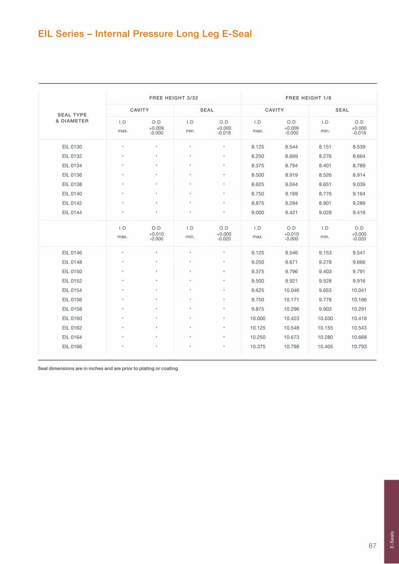
87 E-S
eals
FREE HEIGHT 3/32 FREE HEIGHT 1/8
CAVITY SEAL CAVITY SEAL
I.D O.D I.D O.D I.D O.D I.D O.D +0.009 +0.000 +0.009 +0.000 -0.000 -0.018 -0.000 -0.018
EIL 0130 • • • • 8.125 8.544 8.151 8.539
EIL 0132 • • • • 8.250 8.669 8.276 8.664
EIL 0134 • • • • 8.375 8.794 8.401 8.789
EIL 0136 • • • • 8.500 8.919 8.526 8.914
EIL 0138 • • • • 8.625 9.044 8.651 9.039
EIL 0140 • • • • 8.750 9.169 8.776 9.164
EIL 0142 • • • • 8.875 9.294 8.901 9.289
EIL 0144 • • • • 9.000 9.421 9.028 9.416
I.D O.D I.D O.D I.D O.D I.D O.D +0.010 +0.000 +0.010 +0.000 -0.000 -0.020 -0.000 -0.020
EIL 0146 • • • • 9.125 9.546 9.153 9.541
EIL 0148 • • • • 9.250 9.671 9.278 9.666
EIL 0150 • • • • 9.375 9.796 9.403 9.791
EIL 0152 • • • • 9.500 9.921 9.528 9.916
EIL 0154 • • • • 9.625 10.046 9.653 10.041
EIL 0156 • • • • 9.750 10.171 9.778 10.166
EIL 0158 • • • • 9.875 10.296 9.903 10.291
EIL 0160 • • • • 10.000 10.423 10.030 10.418
EIL 0162 • • • • 10.125 10.548 10.155 10.543
EIL 0164 • • • • 10.250 10.673 10.280 10.668
EIL 0166 • • • • 10.375 10.798 10.405 10.793
SEAL TYPE& DIAMETER
max. min. max. min.
Seal dimensions are in inches and are prior to plating or coating
max. min. max. min.
EIL Series – Internal Pressure Long Leg E-Seal
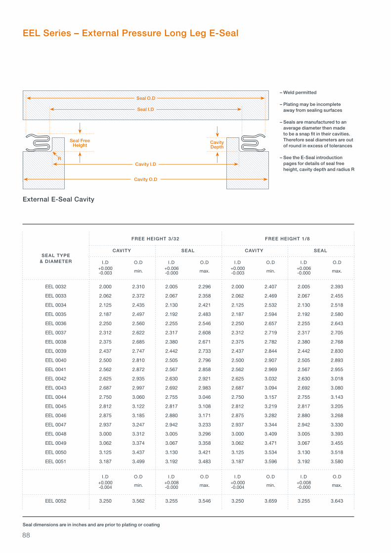
88
– Weld permitted
– Plating may be incomplete away from sealing surfaces
– Seals are manufactured to an average diameter then made to be a snap fit in their cavities. Therefore seal diameters are out of round in excess of tolerances
– See the E-Seal introduction pages for details of seal free height, cavity depth and radius R
SEAL TYPE& DIAMETER
min. max. min. max.
min. max. min. max.
CavityDepth
Cavity O.D
Cavity I.D
Seal O.D
R
Seal FreeHeight
Seal I.D
Seal dimensions are in inches and are prior to plating or coating
FREE HEIGHT 3/32 FREE HEIGHT 1/8
CAVITY SEAL CAVITY SEAL
I.D O.D I.D O.D I.D O.D I.D O.D +0.000 +0.006 +0.000 +0.006 -0.003 -0.000 -0.003 -0.000
EEL 0032 2.000 2.310 2.005 2.296 2.000 2.407 2.005 2.393
EEL 0033 2.062 2.372 2.067 2.358 2.062 2.469 2.067 2.455
EEL 0034 2.125 2.435 2.130 2.421 2.125 2.532 2.130 2.518
EEL 0035 2.187 2.497 2.192 2.483 2.187 2.594 2.192 2.580
EEL 0036 2.250 2.560 2.255 2.546 2.250 2.657 2.255 2.643
EEL 0037 2.312 2.622 2.317 2.608 2.312 2.719 2.317 2.705
EEL 0038 2.375 2.685 2.380 2.671 2.375 2.782 2.380 2.768
EEL 0039 2.437 2.747 2.442 2.733 2.437 2.844 2.442 2.830
EEL 0040 2.500 2.810 2.505 2.796 2.500 2.907 2.505 2.893
EEL 0041 2.562 2.872 2.567 2.858 2.562 2.969 2.567 2.955
EEL 0042 2.625 2.935 2.630 2.921 2.625 3.032 2.630 3.018
EEL 0043 2.687 2.997 2.692 2.983 2.687 3.094 2.692 3.080
EEL 0044 2.750 3.060 2.755 3.046 2.750 3.157 2.755 3.143
EEL 0045 2.812 3.122 2.817 3.108 2.812 3.219 2.817 3.205
EEL 0046 2.875 3.185 2.880 3.171 2.875 3.282 2.880 3.268
EEL 0047 2.937 3.247 2.942 3.233 2.937 3.344 2.942 3.330
EEL 0048 3.000 3.312 3.005 3.296 3.000 3.409 3.005 3.393
EEL 0049 3.062 3.374 3.067 3.358 3.062 3.471 3.067 3.455
EEL 0050 3.125 3.437 3.130 3.421 3.125 3.534 3.130 3.518
EEL 0051 3.187 3.499 3.192 3.483 3.187 3.596 3.192 3.580
I.D O.D I.D O.D I.D O.D I.D O.D +0.000 +0.008 +0.000 +0.008 -0.004 -0.000 -0.004 -0.000
EEL 0052 3.250 3.562 3.255 3.546 3.250 3.659 3.255 3.643
EEL Series – External Pressure Long Leg E-Seal
External E-Seal Cavity

89 E-S
eals
min. max. min. max.
FREE HEIGHT 3/32 FREE HEIGHT 1/8
CAVITY SEAL CAVITY SEAL
I.D O.D I.D O.D I.D O.D I.D O.D +0.000 +0.008 +0.000 +0.008 -0.004 -0.000 -0.004 -0.000
EEL 0053 3.312 3.624 3.317 3.608 3.312 3.721 3.317 3.705
EEL 0054 3.375 3.687 3.380 3.671 3.375 3.784 3.380 3.768
EEL 0055 3.437 3.749 3.442 3.733 3.437 3.846 3.442 3.830
EEL 0056 3.500 3.812 3.505 3.796 3.500 3.909 3.505 3.893
EEL 0057 3.562 3.874 3.567 3.858 3.562 3.971 3.567 3.955
EEL 0058 3.625 3.937 3.630 3.921 3.625 4.034 3.630 4.018
EEL 0059 3.687 3.999 3.692 3.983 3.687 4.096 3.692 4.080
EEL 0060 3.750 4.062 3.755 4.046 3.750 4.159 3.755 4.143
EEL 0061 3.812 4.124 3.817 4.108 3.812 4.221 3.817 4.205
EEL 0062 3.875 4.187 3.880 4.171 3.875 4.284 3.880 4.268
EEL 0063 3.937 4.249 3.942 4.233 3.937 4.346 3.942 4.330
EEL 0064 4.000 4.314 4.005 4.296 4.000 4.411 4.005 4.393
EEL 0065 4.062 4.376 4.067 4.358 4.062 4.473 4.067 4.455
EEL 0066 4.125 4.439 4.130 4.421 4.125 4.536 4.130 4.518
EEL 0067 4.187 4.501 4.192 4.483 4.187 4.598 4.192 4.580
I.D O.D I.D O.D I.D O.D I.D O.D +0.000 +0.010 +0.000 +0.010 -0.005 -0.000 -0.005 -0.000
EEL 0068 4.250 4.564 4.255 4.546 4.250 4.661 4.255 4.643
EEL 0069 4.312 4.626 4.317 4.608 4.312 4.723 4.317 4.705
EEL 0070 4.375 4.689 4.380 4.671 4.375 4.786 4.380 4.768
EEL 0071 4.437 4.751 4.442 4.733 4.437 4.848 4.442 4.830
EEL 0072 4.500 4.814 4.505 4.796 4.500 4.911 4.505 4.893
EEL 0073 4.562 4.876 4.567 4.858 4.562 4.973 4.567 4.955
EEL 0074 4.625 4.939 4.630 4.921 4.625 5.036 4.630 5.018
EEL 0075 4.687 5.001 4.692 4.983 4.687 5.098 4.692 5.080
EEL 0076 4.750 5.064 4.755 5.046 4.750 5.161 4.755 5.143
EEL 0077 4.812 5.126 4.817 5.108 4.812 5.223 4.817 5.205
EEL 0078 4.875 5.189 4.880 5.171 4.875 5.286 4.880 5.268
EEL 0079 4.937 5.251 4.942 5.233 4.937 5.348 4.942 5.330
EEL 0080 5.000 5.316 5.005 5.296 5.000 5.413 5.005 5.393
EEL 0081 5.062 5.378 5.067 5.358 5.062 5.475 5.067 5.455
EEL 0082 5.125 5.441 5.130 5.421 5.125 5.538 5.130 5.518
I.D O.D I.D O.D I.D O.D I.D O.D +0.000 +0.012 +0.000 +0.012 -0.006 -0.000 -0.006 -0.000
EEL 0083 5.187 5.503 5.192 5.483 5.187 5.600 5.192 5.580
EEL 0084 5.250 5.566 5.255 5.546 5.250 5.663 5.255 5.643
EEL 0085 5.312 5.628 5.317 5.608 5.312 5.725 5.317 5.705
SEAL TYPE& DIAMETER
Seal dimensions are in inches and are prior to plating or coating
min. max. min. max.
min. max. min. max.
EEL Series – External Pressure Long Leg E-Seal
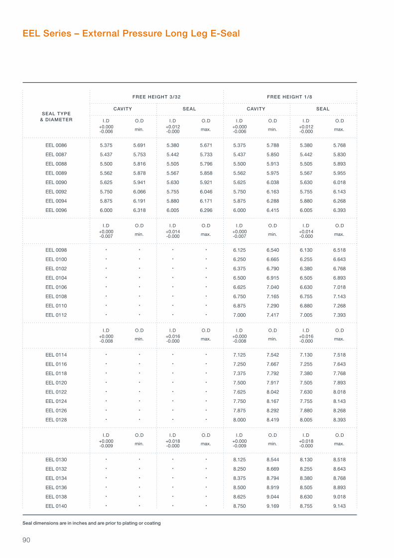
90
min. max. min. max.
FREE HEIGHT 3/32 FREE HEIGHT 1/8
CAVITY SEAL CAVITY SEAL
I.D O.D I.D O.D I.D O.D I.D O.D +0.000 +0.012 +0.000 +0.012 -0.006 -0.000 -0.006 -0.000
EEL 0086 5.375 5.691 5.380 5.671 5.375 5.788 5.380 5.768
EEL 0087 5.437 5.753 5.442 5.733 5.437 5.850 5.442 5.830
EEL 0088 5.500 5.816 5.505 5.796 5.500 5.913 5.505 5.893
EEL 0089 5.562 5.878 5.567 5.858 5.562 5.975 5.567 5.955
EEL 0090 5.625 5.941 5.630 5.921 5.625 6.038 5.630 6.018
EEL 0092 5.750 6.066 5.755 6.046 5.750 6.163 5.755 6.143
EEL 0094 5.875 6.191 5.880 6.171 5.875 6.288 5.880 6.268
EEL 0096 6.000 6.318 6.005 6.296 6.000 6.415 6.005 6.393
I.D O.D I.D O.D I.D O.D I.D O.D +0.000 +0.014 +0.000 +0.014 -0.007 -0.000 -0.007 -0.000
EEL 0098 • • • • 6.125 6.540 6.130 6.518
EEL 0100 • • • • 6.250 6.665 6.255 6.643
EEL 0102 • • • • 6.375 6.790 6.380 6.768
EEL 0104 • • • • 6.500 6.915 6.505 6.893
EEL 0106 • • • • 6.625 7.040 6.630 7.018
EEL 0108 • • • • 6.750 7.165 6.755 7.143
EEL 0110 • • • • 6.875 7.290 6.880 7.268
EEL 0112 • • • • 7.000 7.417 7.005 7.393
I.D O.D I.D O.D I.D O.D I.D O.D +0.000 +0.016 +0.000 +0.016 -0.008 -0.000 -0.008 -0.000
EEL 0114 • • • • 7.125 7.542 7.130 7.518
EEL 0116 • • • • 7.250 7.667 7.255 7.643
EEL 0118 • • • • 7.375 7.792 7.380 7.768
EEL 0120 • • • • 7.500 7.917 7.505 7.893
EEL 0122 • • • • 7.625 8.042 7.630 8.018
EEL 0124 • • • • 7.750 8.167 7.755 8.143
EEL 0126 • • • • 7.875 8.292 7.880 8.268
EEL 0128 • • • • 8.000 8.419 8.005 8.393
I.D O.D I.D O.D I.D O.D I.D O.D +0.000 +0.018 +0.000 +0.018 -0.009 -0.000 -0.009 -0.000
EEL 0130 • • • • 8.125 8.544 8.130 8.518
EEL 0132 • • • • 8.250 8.669 8.255 8.643
EEL 0134 • • • • 8.375 8.794 8.380 8.768
EEL 0136 • • • • 8.500 8.919 8.505 8.893
EEL 0138 • • • • 8.625 9.044 8.630 9.018
EEL 0140 • • • • 8.750 9.169 8.755 9.143
SEAL TYPE& DIAMETER
Seal dimensions are in inches and are prior to plating or coating
min. max. min. max.
min. max. min. max.
min. max. min. max.
EEL Series – External Pressure Long Leg E-Seal

91 E-S
eals
min. max. min. max.
FREE HEIGHT 3/32 FREE HEIGHT 1/8
CAVITY SEAL CAVITY SEAL
I.D O.D I.D O.D I.D O.D I.D O.D +0.000 +0.018 +0.000 +0.018 -0.009 -0.000 -0.009 -0.000
EEL 0142 • • • • 8.875 9.294 8.880 9.268
EEL 0144 • • • • 9.000 9.421 9.005 9.393
I.D O.D I.D O.D I.D O.D I.D O.D +0.000 +0.020 +0.000 +0.020 -0.010 -0.000 -0.010 -0.000
EEL 0146 • • • • 9.125 9.546 9.130 9.518
EEL 0148 • • • • 9.250 9.671 9.255 9.643
EEL 0150 • • • • 9.375 9.796 9.380 9.768
EEL 0152 • • • • 9.500 9.921 9.505 9.893
EEL 0154 • • • • 9.625 10.046 9.630 10.018
EEL 0156 • • • • 9.750 10.171 9.755 10.143
EEL 0158 • • • • 9.875 10.296 9.880 10.268
EEL 0160 • • • • 10.000 10.423 10.005 10.393
I.D O.D I.D O.D I.D O.D I.D O.D +0.000 +0.022 +0.000 +0.022 -0.011 -0.000 -0.011 -0.000
EEL 0162 • • • • 10.125 10.548 10.130 10.518
EEL 0164 • • • • 10.250 10.673 10.255 10.643
EEL 0166 • • • • 10.375 10.798 10.380 10.768
EEL 0168 • • • • 10.500 10.923 10.505 10.893
EEL 0170 • • • • 10.625 11.048 10.630 11.018
EEL 0172 • • • • 10.750 11.173 10.755 11.143
EEL 0174 • • • • 10.875 11.298 10.880 11.268
EEL 0176 • • • • 11.000 11.425 11.005 11.393
I.D O.D I.D O.D I.D O.D I.D O.D +0.000 +0.024 +0.000 +0.024 -0.012 -0.000 -0.012 -0.000
EEL 0178 • • • • 11.125 11.550 11.130 11.518
EEL 0180 • • • • 11.250 11.675 11.255 11.643
EEL 0182 • • • • 11.375 11.800 11.380 11.768
EEL 0184 • • • • 11.500 11.925 11.505 11.893
EEL 0186 • • • • 11.625 12.050 11.630 12.018
EEL 0188 • • • • 11.750 12.175 11.755 12.143
EEL 0190 • • • • 11.875 12.300 11.880 12.268
EEL 0192 • • • • 12.000 12.427 12.005 12.393
SEAL TYPE& DIAMETER
Seal dimensions are in inches and are prior to plating or coating
min. max. min. max.
min. max. min. max.
min. max. min. max.
EEL Series – External Pressure Long Leg E-Seal

92
min. max. min. max.
FREE HEIGHT 3/32 FREE HEIGHT 1/8
CAVITY SEAL CAVITY SEAL
I.D O.D I.D O.D I.D O.D I.D O.D +0.000 +0.026 +0.000 +0.026 -0.013 -0.000 -0.013 -0.000
EEL 0194 • • • • 12.125 12.552 12.130 12.518
EEL 0196 • • • • 12.250 12.677 12.255 12.643
EEL 0198 • • • • 12.375 12.802 12.380 12.768
EEL 0200 • • • • 12.500 12.927 12.505 12.893
EEL 0202 • • • • 12.625 13.052 12.630 13.018
EEL 0204 • • • • 12.750 13.177 12.755 13.143
EEL 0206 • • • • 12.875 13.302 12.880 13.268
EEL 0208 • • • • 13.000 13.427 13.005 13.393
EEL 0210 • • • • 13.125 13.552 13.130 13.518
SEAL TYPE& DIAMETER
Seal dimensions are in inches and are prior to plating or coating
EEL Series – External Pressure Long Leg E-Seal

93 E-S
eals

94
Load
0.0 2.0 4.0 6.0 8.0 10.0 12.0 14.060
70
80
90
100
110
120
DIAMETER ( IN)
LO
AD
(L
BF
/IN
CIR
C.)
0.010 IN
MATERIAL THICKNESS
0.0 2.0 4.0 6.0 8.0 10.0 12.0 14.0 16.0 18.090
100
110
120
130
140
150
160
DIAMETER ( IN)
MATERIAL THICKNESS
0.015 IN
LO
AD
(L
BF
/IN
CIR
C.)
1/8 Section Short Leg Seating Load
3/32 Section Short Leg Seating Load
The seating loads for each seal section are shown below. The values shown are for solution and long cycle precipitation heat treated Inconel 718 seals. These values are for guidance only as a number of factors can have a significant effect on the load including:
– Seal diameter– Seal free height– Cavity depth– Tolerances– Variations in material thickness and properties– Coatings and platings
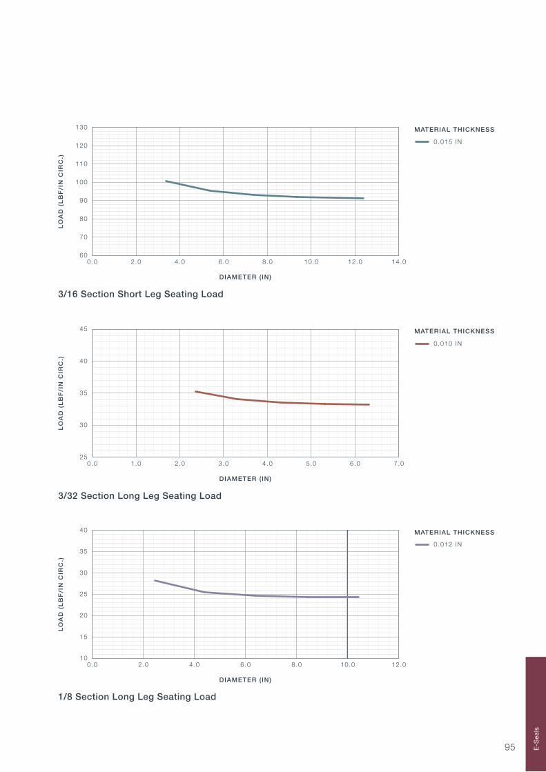
95
0.0 2.0 4.0 6.0 8.0 10.0 12.0 14.060
70
80
90
100
110
120
130
DIAMETER ( IN)
LO
AD
(L
BF
/IN
CIR
C.)
MATERIAL THICKNESS
0.015 IN
MATERIAL THICKNESS
0.0 1.0 2.0 3.0 4.0 5.0 6.0 7.025
30
35
40
45
0.010 IN
DIAMETER ( IN)
LO
AD
(L
BF
/IN
CIR
C.)
0.0 2.0 4.0 6.0 8.0 10.0 12.010
15
20
25
30
35
40
DIAMETER ( IN)
0.012 IN
LO
AD
(L
BF
/IN
CIR
C.)
MATERIAL THICKNESS
3/32 Section Long Leg Seating Load
1/8 Section Long Leg Seating Load
3/16 Section Short Leg Seating Load
E-S
eals
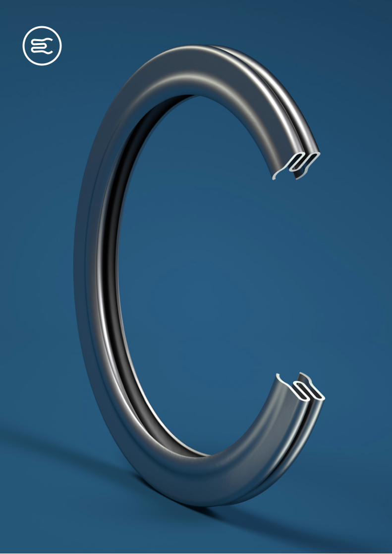
96

97
Product DescriptionHigh Temperature Duct Seal SpecificationPart List (S2283–XXX Series)Part List (S2283–XXX-SP Series)Part List (S2314–XXX Series)Part List (S2346–XXX Series)Part List (S2347–XXX Series)Cross Reference Table
High Temperature Duct Seals
9899100101102103104105
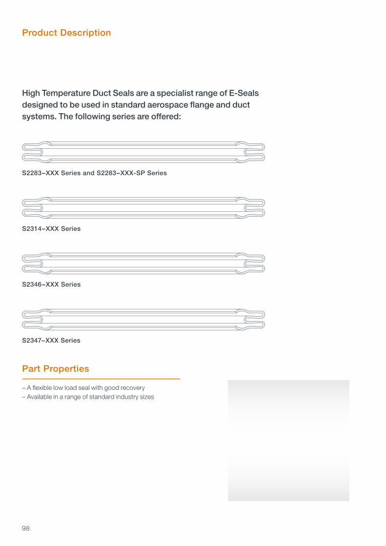
98
Product Description
S2283–XXX Series and S2283–XXX-SP Series
S2314–XXX Series
S2346–XXX Series
S2347–XXX Series
High Temperature Duct Seals are a specialist range of E-Seals designed to be used in standard aerospace flange and duct systems. The following series are offered:
Part Properties
– A flexible low load seal with good recovery– Available in a range of standard industry sizes
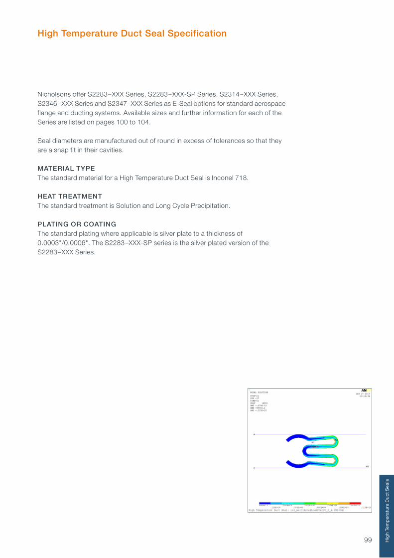
99
High Temperature Duct Seal Specification
Nicholsons offer S2283–XXX Series, S2283–XXX-SP Series, S2314–XXX Series, S2346–XXX Series and S2347–XXX Series as E-Seal options for standard aerospace flange and ducting systems. Available sizes and further information for each of the Series are listed on pages 100 to 104.
Seal diameters are manufactured out of round in excess of tolerances so that they are a snap fit in their cavities. MATERIAL TYPEThe standard material for a High Temperature Duct Seal is Inconel 718.
HEAT TREATMENTThe standard treatment is Solution and Long Cycle Precipitation.
PLATING OR COATINGThe standard plating where applicable is silver plate to a thickness of 0.0003"/0.0006". The S2283–XXX-SP series is the silver plated version of the S2283–XXX Series.
Hig
h T
emp
erat
ure
Du
ct S
eals

100
Part List – S2283–XXX Series
S2283-700 6.958 7.00 AS1895/7-700
S2283-750 7.458 7.50 A2873-750
6.749 0.113 0.011 0.065 6.735 0.103 0.009 0.045
7.249 0.113 0.011 0.065 7.235 0.103 0.009 0.045
7.749 0.113 0.011 0.065 7.733 0.103 0.009 0.045
S2283-250 2.458 2.50
S2283-150 1.458 1.50
S2283-125 1.208 1.25 1.499 0.113 0.011 0.040 A3478 1.495 0.103 0.009 0.020 AS1895/7-125
1.749 0.113 0.011 0.040 A0944 1.745 0.103 0.009 0.020 AS1895/7-150
1.999 0.113 0.011 0.040 A3624 1.995 0.103 0.009 0.020 AS1895/7-175
2.249 0.113 0.011 0.040 A0945 2.245 0.103 0.009 0.020 AS1895/7-200
2.499 0.113 0.011 0.040 A3505 2.493 0.103 0.009 0.020 AS1895/7-225
2.749 0.113 0.011 0.040 A0946 2.743 0.103 0.009 0.020 AS1895/7-250
1.249 0.113 0.011 0.040 A3475 1.245 0.103 0.009 0.020 AS1895/7-100
SEAL
PARTNUMBER
OUT OF ROUNDNESS
OF OUTER DIAMETER
O.DI.D
(REF)FREE
HT.MAT’L
THK
DUCTSIZE
EQUIVALENTTO
S2283-100 0.958 1.00
S2283-175 1.708 1.75
S2283-200 1.958 2.00
S2283-225 2.208 2.25
S2283-275 2.708 2.75
S2283-300 2.958 3.00
S2283-325 3.208 3.25
S2283-350 3.458 3.50
S2283-400 3.958 4.00
S2283-450 4.458 4.50
S2283-500 4.958 5.00
S2283-550 5.458 5.50
S2283-600 5.958 6.00
S2283-650 6.458 6.50 AS1895/7-650
2.999 0.113 0.011 0.040 A2873-275 2.993 0.103 0.009 0.020 AS1895/7-275
3.249 0.113 0.011 0.040 A2873-300 3.243 0.103 0.009 0.020 AS1895/7-300
3.499 0.113 0.011 0.040 A2873-325 3.491 0.103 0.009 0.020 AS1895/7-325
3.749 0.113 0.011 0.050 A2873-350 3.741 0.103 0.009 0.030 AS1895/7-350
4.249 0.113 0.011 0.050 A2873-400 4.241 0.103 0.009 0.030 AS1895/7-400
4.749 0.113 0.011 0.050 A2873-450 4.739 0.103 0.009 0.030 AS1895/7-450
5.249 0.113 0.011 0.060 A2873-500 5.239 0.103 0.009 0.040 AS1895/7-500
5.749 0.113 0.011 0.060 A2873-550 5.737 0.103 0.009 0.040 AS1895/7-550
6.249 0.113 0.011 0.060 A2873-600 6.237 0.103 0.009 0.040 AS1895/7-600
Seal dimensions are in inches and are prior to plating or coating

101
Part List – S2283–XXX-SP Series
S2283-700-SP 6.958 7.00 AS1895/7-700
S2283-750-SP 7.458 7.50 A2873-750
6.749 0.113 0.011 0.065 6.735 0.103 0.009 0.045
7.249 0.113 0.011 0.065 7.235 0.103 0.009 0.045
7.749 0.113 0.011 0.065 7.733 0.103 0.009 0.045
S2283-250-SP 2.458 2.50
S2283-150-SP 1.458 1.50
S2283-125-SP 1.208 1.25 1.499 0.113 0.011 0.040 A3478 1.495 0.103 0.009 0.020 AS1895/7-125
1.749 0.113 0.011 0.040 A0944 1.745 0.103 0.009 0.020 AS1895/7-150
1.999 0.113 0.011 0.040 A3624 1.995 0.103 0.009 0.020 AS1895/7-175
2.249 0.113 0.011 0.040 A0945 2.245 0.103 0.009 0.020 AS1895/7-200
2.499 0.113 0.011 0.040 A3505 2.493 0.103 0.009 0.020 AS1895/7-225
2.749 0.113 0.011 0.040 A0946 2.743 0.103 0.009 0.020 AS1895/7-250
1.249 0.113 0.011 0.040 A3475 1.245 0.103 0.009 0.020 AS1895/7-100
SEAL
PARTNUMBER
OUT OF ROUNDNESS
OF OUTER DIAMETER
O.DI.D
(REF)FREE
HT.MAT’L
THK
DUCTSIZE
EQUIVALENTTO
S2283-100-SP 0.958 1.00
S2283-175-SP 1.708 1.75
S2283-200-SP 1.958 2.00
S2283-225-SP 2.208 2.25
S2283-275-SP 2.708 2.75
S2283-300-SP 2.958 3.00
S2283-325-SP 3.208 3.25
S2283-350-SP 3.458 3.50
S2283-400-SP 3.958 4.00
S2283-450-SP 4.458 4.50
S2283-500-SP 4.958 5.00
S2283-550-SP 5.458 5.50
S2283-600-SP 5.958 6.00
S2283-650-SP 6.458 6.50 AS1895/7-650
2.999 0.113 0.011 0.040 A2873-275 2.993 0.103 0.009 0.020 AS1895/7-275
3.249 0.113 0.011 0.040 A2873-300 3.243 0.103 0.009 0.020 AS1895/7-300
3.499 0.113 0.011 0.040 A2873-325 3.491 0.103 0.009 0.020 AS1895/7-325
3.749 0.113 0.011 0.050 A2873-350 3.741 0.103 0.009 0.030 AS1895/7-350
4.249 0.113 0.011 0.050 A2873-400 4.241 0.103 0.009 0.030 AS1895/7-400
4.749 0.113 0.011 0.050 A2873-450 4.739 0.103 0.009 0.030 AS1895/7-450
5.249 0.113 0.011 0.060 A2873-500 5.239 0.103 0.009 0.040 AS1895/7-500
5.749 0.113 0.011 0.060 A2873-550 5.737 0.103 0.009 0.040 AS1895/7-550
6.249 0.113 0.011 0.060 A2873-600 6.237 0.103 0.009 0.040 AS1895/7-600
Seal dimensions are in inches and are prior to plating or coating
Hig
h T
emp
erat
ure
Du
ct S
eals
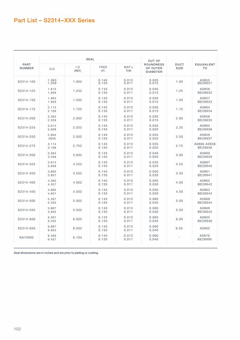
102
NA10092 6.104 •
S2314-650 6.502 6.50 A2802 6.867 0.145 0.013 0.060 6.855 0.135 0.011 0.040
S2314-250 2.502 2.50
S2314-150 1.502 1.50
S2314-125 1.252 1.25
S2314-100 1.002 1.00
S2314-175 1.752 1.75
S2314-200 2.002 2.00
S2314-225 2.252 2.25
S2314-275 2.752 2.75
S2314-300 3.002 3.00
S2314-325 3.252 3.25
S2314-350 3.502 3.50
S2314-400 4.002 4.00
S2314-450 4.502 4.50
S2314-500 5.002 5.00
S2314-550 5.502 5.50
S2314-600 6.002 6.00 6.367 0.145 0.013 0.065 A0805 6.355 0.135 0.011 0.045 BE28946
5.867 0.145 0.013 0.060 A0869 5.855 0.135 0.011 0.040 BE28945
5.367 0.145 0.013 0.060 A0868 5.355 0.135 0.011 0.040 BE28944
4.865 0.145 0.013 0.050 A0863 4.857 0.135 0.011 0.030 BE28943
4.365 0.145 0.013 0.050 A0862 4.357 0.135 0.011 0.030 BE28942
3.865 0.145 0.013 0.050 A0861 3.857 0.135 0.011 0.030 BE28941
3.614 0.145 0.013 0.035 A0867 3.608 0.135 0.011 0.020 BE28940
3.114 0.145 0.013 0.035 A0866 A0938 3.108 0.135 0.011 0.020 BE28938
3.364 0.145 0.013 0.040 A0860 3.358 0.135 0.011 0.020 BE28939
2.864 0.145 0.013 0.035 A0859 2858 0.135 0.011 0.020 BE28937
1.863 0.145 0.013 0.030 A0857 1.859 0.135 0.011 0.015 BE28933
1.613 0.145 0.013 0.030 A0856 1.609 0.135 0.011 0.015 BE28932
Part List – S2314–XXX Series
2.113 0.145 0.013 0.030 A0864 2.109 0.135 0.011 0.015 BE28934
2.363 0.145 0.013 0.030 A0858 2.359 0.135 0.011 0.015 BE28935
2.614 0.145 0.013 0.035 A0865 2.608 0.135 0.011 0.020 BE28936
1.363 0.145 0.013 0.030 A0855 1.359 0.135 0.011 0.015 BE28931
SEAL
PARTNUMBER
OUT OF ROUNDNESS
OF OUTER DIAMETER
O.DI.D
(REF)FREE
HT.MAT’L
THK
DUCTSIZE
EQUIVALENTTO
6.469 0.145 0.013 0.060 A0870 6.457 0.135 0.011 0.040 BE28990
Seal dimensions are in inches and are prior to plating or coating

103
S2346-250 2.578 2.50 A7387-250
S2346-150 1.579 1.50 A7387-150
S2346-125 1.329 1.25 A7387-125
S2346-100 1.079 1.00 A7387-100
S2346-175 1.829 1.75 A7387-175
S2346-200 2.079 2.00 A7387-200
S2346-225 2.329 2.25 A7387-225
S2346-275 2.828 2.75 A7387-275
S2346-300 3.078 3.00 A7387-300
S2346-325 3.327 3.25 A7387-325
S2346-350 3.577 3.50 A7387-350
S2346-400 4.077 4.00 A7387-400
S2346-450 4.575 4.50 A7387-450
S2346-500 5.075 5.00 A7387-500
S2346-550 5.573 5.50 A7387-550
S2346-600 6.073 6.00 A7387-600
Part List – S2346–XXX Series
SEAL
PARTNUMBER
OUT OF ROUNDNESS
OF OUTER DIAMETER
O.DI.D
(REF)FREE
HT.MAT’L
THK
DUCTSIZE
EQUIVALENTTO
Seal dimensions are in inches and are prior to plating or coating
6.365 0.113 0.011 0.065 6.353 0.103 0.009 0.045
5.865 0.113 0.011 0.065 5.853 0.103 0.009 0.045
5.365 0.113 0.011 0.060 5.353 0.103 0.009 0.040
4.865 0.113 0.011 0.060 4.855 0.103 0.009 0.040
4.365 0.113 0.011 0.050 4.357 0.103 0.009 0.035
3.865 0.113 0.011 0.050 3.857 0.103 0.009 0.035
3.615 0.113 0.011 0.050 3.607 0.103 0.009 0.035
3.115 0.113 0.011 0.045 3.109 0.103 0.009 0.030
3.365 0.113 0.011 0.045 3.359 0.103 0.009 0.030
2.865 0.113 0.011 0.045 2.859 0.103 0.009 0.030
1.865 0.113 0.011 0.035 1.861 0.103 0.009 0.025
1.615 0.113 0.011 0.035 1.611 0.103 0.009 0.025
2.115 0.113 0.011 0.035 2.111 0.103 0.009 0.025
2.365 0.113 0.011 0.040 2.361 0.103 0.009 0.025
2.615 0.113 0.011 0.040 2.609 0.103 0.009 0.025
1.365 0.113 0.011 0.035 1.361 0.103 0.009 0.025
Hig
h T
emp
erat
ure
Du
ct S
eals
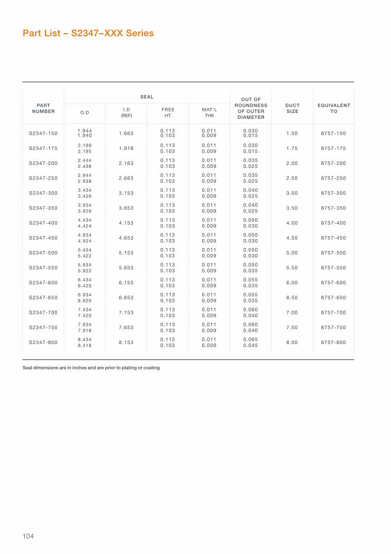
104
Part List – S2347–XXX Series
S2347-400 4.153 4.00 8757-400
S2347-200 2.163 2.00 8757-200
S2347-175 1.918 1.75 8757-175
S2347-150 1.663 1.50 8757-150
S2347-250 2.663 2.50 8757-250
S2347-300 3.153 3.00 8757-300
S2347-350 3.653 3.50 8757-350
S2347-450 4.653 4.50 8757-450
S2347-500 5.153 5.00 8757-500
S2347-550 5.653 5.50 8757-550
S2347-600 6.153 6.00 8757-600
S2347-650 6.653 6.50 8757-650
S2347-700 7.153 7.00 8757-700
S2347-750 7.653 7.50 8757-750
S2347-800 8.153 8.00 8757-800 8.434 0.113 0.011 0.065 8.418 0.103 0.009 0.045
7.934 0.113 0.011 0.060 7.918 0.103 0.009 0.040
7.434 0.113 0.011 0.060 7.420 0.103 0.009 0.040
6.934 0.113 0.011 0.055 6.920 0.103 0.009 0.035
6.434 0.113 0.011 0.055 6.420 0.103 0.009 0.035
5.934 0.113 0.011 0.050 5.922 0.103 0.009 0.035
4.934 0.113 0.011 0.050 4.924 0.103 0.009 0.030
5.434 0.113 0.011 0.050 5.422 0.103 0.009 0.030
4.434 0.113 0.011 0.050 4.424 0.103 0.009 0.030
2.444 0.113 0.011 0.035 2.438 0.103 0.009 0.025
2.199 0.113 0.011 0.030 2.195 0.103 0.009 0.015
2.944 0.113 0.011 0.035 2.938 0.103 0.009 0.025
3.434 0.113 0.011 0.040 3.426 0.103 0.009 0.025
3.934 0.113 0.011 0.040 3.926 0.103 0.009 0.025
1.944 0.113 0.011 0.030 1.940 0.103 0.009 0.015
SEAL
PARTNUMBER
OUT OF ROUNDNESS
OF OUTER DIAMETER
O.DI.D
(REF)FREE
HT.MAT’L
THK
DUCTSIZE
EQUIVALENTTO
Seal dimensions are in inches and are prior to plating or coating

105
Cross Reference Table
NICHOLSONS PART NUMBER
UNPLATED SEE PAGE SILVER PLATED SEE PAGE
8757-150 S2347-150 p104 - -
8757-175 S2347-175 p104 - -
8757-200 S2347-200 p104 - -
8757-250 S2347-250 p104 - -
8757-300 S2347-300 p104 - -
8757-350 S2347-350 p104 - -
8757-400 S2347-400 p104 - -
8757-450 S2347-450 p104 - -
8757-500 S2347-500 p104 - -
8757-550 S2347-550 p104 - -
8757-600 S2347-600 p104 - -
8757-650 S2347-650 p104 - -
8757-700 S2347-700 p104 - -
8757-750 S2347-750 p104 - -
8757-800 S2347-800 p104 - -
A0805 S2314-600 p102 - -
A0855 S2314-100 p102 - -
A0856 S2314-125 p102 - -
A0857 S2314-150 p102 - -
A0858 S2314-200 p102 - -
A0859 S2314-250 p102 - -
A0860 S2314-300 p102 - -
A0861 S2314-350 p102 - -
A0862 S2314-400 p102 - -
A0863 S2314-450 p102 - -
A0864 S2314-175 p102 - -
A0865 S2314-225 p102 - -
A0866 S2314-275 p102 - -
A0867 S2314-325 p102 - -
A0868 S2314-500 p102 - -
A0869 S2314-550 p102 - -
A0870 NA10092 p102 - -
A0938 S2314-275 p102 - -
A0944 S2283-150 p101 S2283-150-SP p101
A0945 S2283-200 p101 S2283-200-SP p101
A0946 S2283-250 p101 S2283-250-SP p101
A2802 S2314-650 p102 - -
A2873-275 S2283-275 p100 S2283-275-SP p101
A2873-300 S2283-300 p100 S2283-300-SP p101
A2873-325 S2283-325 p100 S2283-325-SP p101
A2873-350 S2283-350 p100 S2283-350-SP p101
A2873-400 S2283-400 p100 S2283-400-SP p101
EQUIVALENTPART NUMBER
Hig
h T
emp
erat
ure
Du
ct S
eals

106
NICHOLSONS PART NUMBER
UNPLATED SEE PAGE SILVER PLATED SEE PAGE
A2873-450 S2283-450 p100 S2283-450-SP p101
A2873-500 S2283-500 p100 S2283-500-SP p101
A2873-550 S2283-550 p100 S2283-550-SP p101
A2873-600 S2283-600 p100 S2283-600-SP p101
A2873-750 S2283-750 p100 S2283-750-SP p101
A3475 S2283-100 p100 S2283-100-SP p101
A3478 S2283-125 p100 S2283-125-SP p101
A3505 S2283-225 p100 S2283-225-SP p101
A3624 S2283-175 p100 S2283-175-SP p101
A7387-100 S2346-100 p103 - -
A7387-125 S2346-125 p103 - -
A7387-150 S2346-150 p103 - -
A7387-175 S2346-175 p103 - -
A7387-200 S2346-200 p103 - -
A7387-225 S2346-225 p103 - -
A7387-250 S2346-250 p103 - -
A7387-275 S2346-275 p103 - -
A7387-300 S2346-300 p103 - -
A7387-325 S2346-325 p103 - -
A7387-350 S2346-350 p103 - -
A7387-400 S2346-400 p103 - -
A7387-450 S2346-450 p103 - -
A7387-500 S2346-500 p103 - -
A7387-550 S2346-550 p103 - -
A7387-600 S2346-600 p103 - -
AS1895/7-100 S2283-100 p100 S2283-100-SP p101
AS1895/7-125 S2283-125 p100 S2283-125-SP p101
AS1895/7-150 S2283-150 p100 S2283-150-SP p101
AS1895/7-175 S2283-175 p100 S2283-175-SP p101
AS1895/7-200 S2283-200 p100 S2283-200-SP p101
AS1895/7-225 S2283-225 p100 S2283-225-SP p101
AS1895/7-250 S2283-250 p100 S2283-250-SP p101
AS1895/7-275 S2283-275 p100 S2283-275-SP p101
AS1895/7-300 S2283-300 p100 S2283-300-SP p101
AS1895/7-325 S2283-325 p100 S2283-325-SP p101
AS1895/7-350 S2283-350 p100 S2283-350-SP p101
AS1895/7-400 S2283-400 p100 S2283-400-SP p101
AS1895/7-450 S2283-450 p100 S2283-450-SP p101
AS1895/7-500 S2283-500 p100 S2283-500-SP p101
AS1895/7-550 S2283-550 p100 S2283-550-SP p101
AS1895/7-600 S2283-600 p100 S2283-600-SP p101
AS1895/7-650 S2283-650 p100 S2283-650-SP p101
EQUIVALENTPART NUMBER

107
NICHOLSONS PART NUMBER
UNPLATED SEE PAGE SILVER PLATED SEE PAGE
AS1895/7-700 S2283-700 p100 S2283-700-SP p101
BE28931 S2314-100 p102 - -
BE28932 S2314-125 p102 - -
BE28933 S2314-150 p102 - -
BE28934 S2314-175 p102 - -
BE28935 S2314-200 p102 - -
BE28936 S2314-225 p102 - -
BE28937 S2314-250 p102 - -
BE28938 S2314-275 p102 - -
BE28939 S2314-300 p102 - -
BE28940 S2314-325 p102 - -
BE28941 S2314-350 p102 - -
BE28942 S2314-400 p102 - -
BE28943 S2314-450 p102 - -
BE28944 S2314-500 p102 - -
BE28945 S2314-550 p102 - -
BE28946 S2314-600 p102 - -
BE28990 NA10092 p102 - -
EQUIVALENTPART NUMBER
Hig
h T
emp
erat
ure
Du
ct S
eals

108
109
Product DescriptionSigma Seal SpecificationStandard Sigma Seal SectionsLoad
Sigma Seals
110111112114
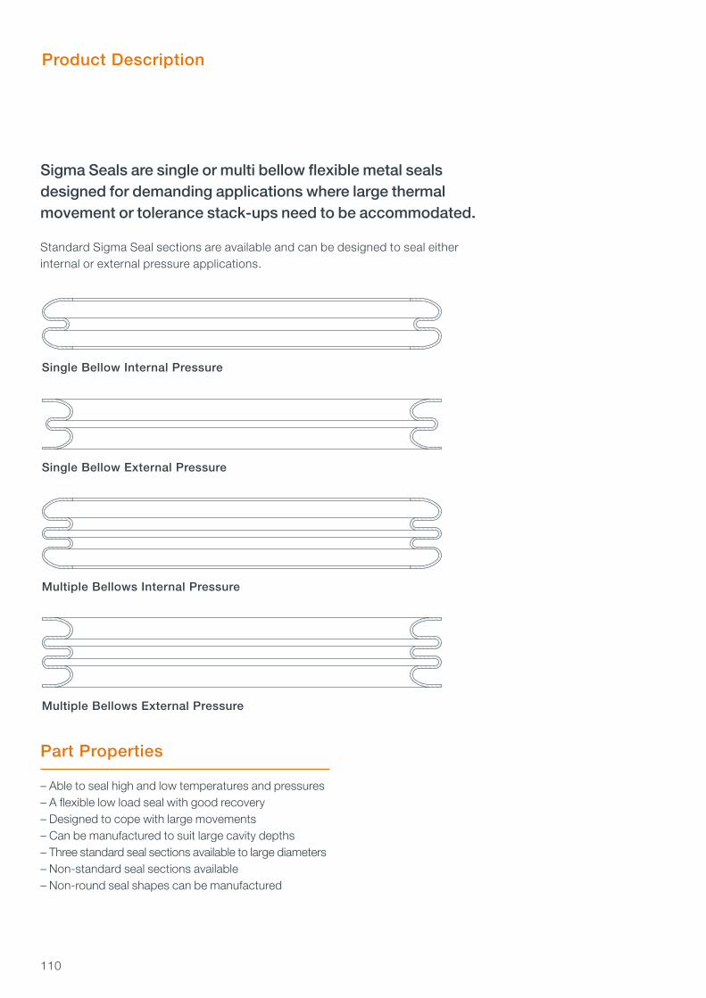
110
Single Bellow Internal Pressure
Single Bellow External Pressure
Multiple Bellows Internal Pressure
Multiple Bellows External Pressure
Sigma Seals are single or multi bellow flexible metal seals designed for demanding applications where large thermal movement or tolerance stack-ups need to be accommodated.
Standard Sigma Seal sections are available and can be designed to seal either internal or external pressure applications.
Product Description
Part Properties
– Able to seal high and low temperatures and pressures– A flexible low load seal with good recovery– Designed to cope with large movements– Can be manufactured to suit large cavity depths– Three standard seal sections available to large diameters– Non-standard seal sections available– Non-round seal shapes can be manufactured

111
Sigma Seal Specification
Sigma Seals are designed on an individual basis to suit the customer’s applications. A standard part list is not available for this product due to the large range of section and diameter options that can be selected.
There are three standard Sigma Seal sections available which are suited to many applications that utilise industry standard flanges. The details of the three standard sections and their corresponding cavity dimensions are shown on pages 112 and 113.
For other applications where standard sections are not appropriate, Nicholsons can design an alternative section to suit your particular requirements. Further options can be found in the Multi Bellow Seals section on page 118.
Please consult us if you require a bespoke design or need any assistance specifying a Sigma Seal or Multi Bellow Seal for your application.
MATERIAL TYPESigma Seal materials are selected according to service requirements. They include high strength nickel alloys such as Inconels, Waspaloy and cobalt based alloys such as Haynes 25. Suitable material options are listed on page 12. Typical material thickness is within the range 0.006" to 0.015".
HEAT TREATMENTFull heat treatment is usually applied to the seal to ensure maximum use of the material properties. Further heat treatment options for this product are listed on page 13.
PLATING OR COATINGThe standard Sigma Seal is uncoated. Plating or coating is available and options are listed on page 14. Wear resistance coatings can be applied to help protect the seal in arduous conditions. Not all plating or coating options are valid for Sigma Seals. Please consult us if you require any assistance in selecting the appropriate plating or coating.
Sig
ma
Sea
ls

112
0.183 0.218 0.179 0.208 3/16 A+0.010 B-(0.020+T2+T4) 0.030 0.120±T3 A A-2WMAX
0.246 0.292 0.242 0.282 1/4 A+0.010 B-(0.020+T2+T4) 0.060 0.167±T3 A A-2WMAX
0.120 0.144 0.116 0.134
CAVITY SEAL
NOMINALSIZE RADIAL
WIDTH WFREE
HEIGHTDEPTH
O.D(min.)
O.D(max.) A
I .D(max.)
I .D(min.) B
CORNER RADIUS(max.) R
1/8 A+0.010 B-(0.020+T2+T4) 0.030 0.083±T3 A A-2WMAX
Cavity O.D
Cavity I.D
Seal O.D
R
CavityDepth
Seal FreeHeight
Seal I.D
Internal Sigma Seal Cavity
Tolerances for Seal Design
Standard Sigma Seal Sections
T4 is the total tolerance on the cavity O/D
SEAL OD TOL T1 SEAL ID TOL T2 SEAL RADIAL WIDTH W +0.000 -0.000 TOL T3
Up to 10.000 -0.010 +0.010 ±0.005
10.001 to 20.000 -0.020 +0.020 ±0.010
20.001 to 30.000 -0.030 +0.030 ±0.015
30.001 and above -0.040 +0.040 ±0.020
SEAL DIAMETERS

113
0.183 0.218 0.179 0.208
0.246 0.292 0.242 0.282
0.120 0.144 0.116 0.134
CAVITY SEAL
NOMINALSIZE RADIAL
WIDTH WFREE
HEIGHTDEPTH
O.D(min.)
O.D(max.) A
I .D(max.)
I .D(min.) B
CORNER RADIUS(max.) R
1/8 A+(0.020+T2+T5) B-0.010 0.030 0.083±T3 B+2WMAX B
3/16 A+(0.020+T2+T5) B-0.010 0.030 0.120±T3 B+2WMAX B
1/4 A+(0.020+T2+T5) B-0.010 0.060 0.167±T3 B+2WMAX B
CavityDepth
Cavity O.D
Cavity I.D
Seal O.D
R
Seal FreeHeight
Seal I.D
External Sigma Seal Cavity
T5 is the total tolerance on the cavity O/D
Sig
ma
Sea
ls

114
0.0 5.0 10.0 15.0 20.0 25.0 30.0 35.0 40.0 45.00
50
100
150
200
250
300
0.015 IN
0.010 IN
0.007 IN
DIAMETER ( IN)
LO
AD
(L
BF
/IN
CIR
C.)
MATERIAL THICKNESS
0.0 5.0 10.0 15.0 20.0 25.0 30.0 35.0 40.0 45.00
50
100
150
200
250
300
350
400
0.020 IN
0.015 IN
0.010 IN
0.007 IN
DIAMETER ( IN)
LO
AD
(L
BF
/IN
CIR
C.)
MATERIAL THICKNESS
1/8 Section Seating Load
3/16 Section Seating Load
Load
The seating loads for each seal section are shown below. The values shown are for long cycle precipitation heat treated Inconel 718 seals. These values are for guidance only as a number of factors can have a significant effect on the load including:
– Seal diameter– Seal free height– Cavity depth– Tolerances– Variations in material thickness and properties– Coatings and platings

115
MATERIAL THICKNESS
0.0 5.0 10.0 15.0 20.0 25.0 30.0 35.0 40.0 45.00
50
100
150
200
250
300
350
400
0.025 IN
0.020 IN
0.015 IN
0.010 IN
DIAMETER ( IN)
LO
AD
(L
BF
/IN
CIR
C.)
1/4 Section Seating Load
Sig
ma
Sea
ls
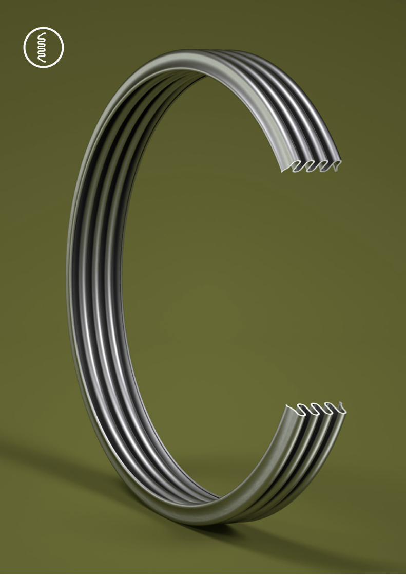
116

117
Product DescriptionMulti Bellow Seal Specification
Multi Bellow Seals
118119

118
Multi Bellow Seals are a range of flexible metal seals that are designed for more specialised applications where a non-standard section is required.
Sometimes referred to as W- or M-Seals, Multi Bellow Seals are particularly suitable for use where the available cavity radial width is limited or where the ratio of cavity radial width to cross section height is less than one.
Large scale vibration and cavity thermal growth can be accommodated by using a multiple bellow configuration. A non-standard section can be designed to produce a seal which exerts a greater specific load at the area of contact than the standard Sigma Seal sections which is beneficial for high pressure applications. Finite Element Analysis is often used during the design process to model the sealing load generated upon the cavity and the structural abilities of the seal to meet required cyclic operating conditions and fatigue life.
Multi Bellow Seals can be designed to seal either internal or external pressure applications. Some seal section examples are shown below.
Product Description
Part Properties
– Able to seal high and low temperatures and pressures– A flexible low load seal with good recovery– Designed to cope with large movements– Can be manufactured to suit large cavity depths– Available in a range of sections to virtually any diameter– Non-round seal shapes can be manufactured
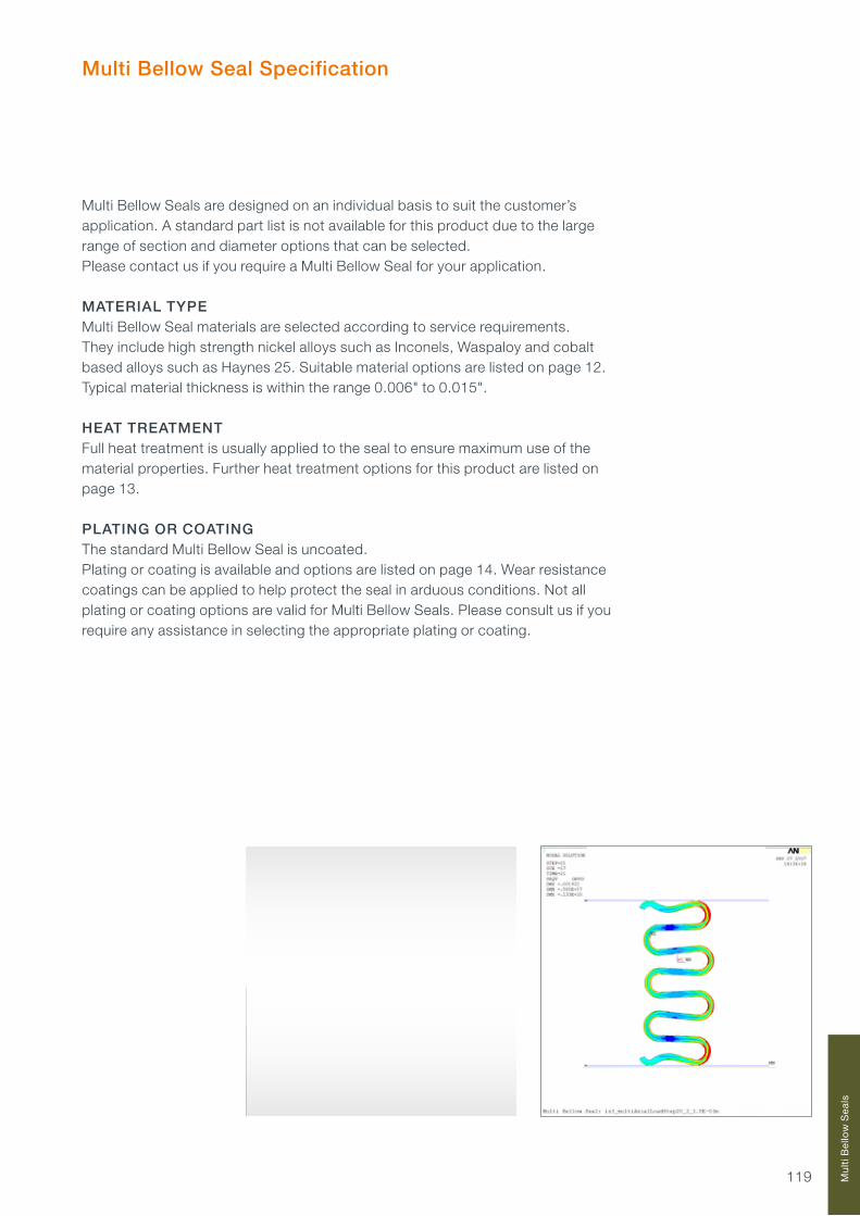
119
Multi Bellow Seal Specification
Multi Bellow Seals are designed on an individual basis to suit the customer’s application. A standard part list is not available for this product due to the large range of section and diameter options that can be selected. Please contact us if you require a Multi Bellow Seal for your application.
MATERIAL TYPEMulti Bellow Seal materials are selected according to service requirements. They include high strength nickel alloys such as Inconels, Waspaloy and cobalt based alloys such as Haynes 25. Suitable material options are listed on page 12.Typical material thickness is within the range 0.006" to 0.015".
HEAT TREATMENTFull heat treatment is usually applied to the seal to ensure maximum use of the material properties. Further heat treatment options for this product are listed on page 13.
PLATING OR COATINGThe standard Multi Bellow Seal is uncoated.Plating or coating is available and options are listed on page 14. Wear resistance coatings can be applied to help protect the seal in arduous conditions. Not all plating or coating options are valid for Multi Bellow Seals. Please consult us if you require any assistance in selecting the appropriate plating or coating.
Mu
lti B
ello
w S
eals
120
Glossary
Axial Seal: A seal that contacts the hardware on the OD and ID.Contact Line: The location at which the seal contacts the hardware.External Seal: A face seal that has higher pressure on its OD.Face Seal: A Seal that contacts the hardware in the axial direction.Free Height: The length of a seal in the axial direction.ID: Inner Diameter.Internal Seal: A face seal that has higher pressure on its ID.Nominal: The value specified in the catalogue or the mid-point
of a toleranced dimension.OD: Outer Diameter.Out-of-round Seal: A seal that is made slightly oval to retain the seal in
the hardware.Radial Width: The width of the seal section in the radial direction
((OD-ID)/2).Seal Compression: The difference between free height and compressed
height.Seal Set: The seal free height minus the height of the seal after
compression.Seating Load: The load required to fully compress the seal.Snap-Fit: The retention of an out-of-round seal in a cavity
regardless of orientation.Springback: The height of seal after compression minus the
compressed height.Witness Line: The visible line on a used seal indicating where contact
between the seal and the hardware has occurred.

Design: Tom Green Design3D Product Illustrations: Floating ElementsPhotography: Sally Ann Norman PhotographyProduct Photography: Dave Lidwell
The information included in this catalogue is for general information purposes only and is not specific to a particular application. Whilst every effort has been made to ensure that all technical data contained within is correct, it is the ultimate responsibility of the customer to ensure that the selected product is suitable for the operating conditions of their individual application, including but not limited to temperature, pressure, compression and coupling materials.
Nicholsons Group assumes no responsibility for errors or omissions for the customer’s incorrect specification or usage of any part, or for the misinterpretation by the customer of any information provided within this catalogue. In no event will Nicholsons Group be liable for any loss, damage claim or expense arising directly or indirectly from the use of any information provided in this catalogue.
The products described herein, including without limitation product types, features, specifications, designs, availability and pricing are subject to change by Nicholsons Group at any time without prior notice.
No reproduction, copy or use of technical data, specifications, images and other information contained herein may be made without the express written permission of Nicholsons Group.

Nicholsons UKNicholsons Sealing Technologies Ltd.Amos DriveGreencroft Industrial ParkStanleyCounty DurhamDH9 7YEUnited KingdomT. +44 (0) 1207 523 010F. +44 (0) 1207 523 011E. [email protected]. www.nicholsons.co.uk
Nicholsons USACorru-Seals, Inc. dba Nicholsons24 Capital DriveWallingfordConnecticut 06492USAT. +1 203 265 9331F. +1 203 269 1023E. [email protected]. www.nicholsons.com
Nicholsons GermanyNicholsons GmbHJohannesstraße 19D-70176 StuttgartGermanyT. +49 175 3606510
Top Related