


Languages
Pages
Legal


Case Study: Strain Rate Effect in Falling Rate Effect in Falling Dart Test Simulation
Steven Hale – CAE AssociatesAccurate FEA of EngineeringAccurate FEA of Engineering
Plastics SeminarOctober 14, 2014
© 2014 CAE Associates
Goal
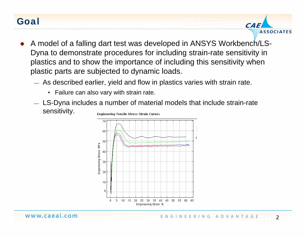
A model of a falling dart test was developed in ANSYS Workbench/LS- A model of a falling dart test was developed in ANSYS Workbench/LS-Dyna to demonstrate procedures for including strain-rate sensitivity in plastics and to show the importance of including this sensitivity when plastic parts are subjected to dynamic loads.plastic parts are subjected to dynamic loads.
— As described earlier, yield and flow in plastics varies with strain rate.• Failure can also vary with strain rate.
LS-Dyna includes a number of material models that include strain-rate— LS-Dyna includes a number of material models that include strain-rate sensitivity.
2
Falling Dart Test
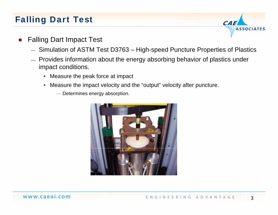
Falling Dart Impact Test Falling Dart Impact Test— Simulation of ASTM Test D3763 – High-speed Puncture Properties of Plastics— Provides information about the energy absorbing behavior of plastics under
impact conditionsimpact conditions.• Measure the peak force at impact• Measure the impact velocity and the “output” velocity after puncture.
— Determines energy absorptionDetermines energy absorption.
3
Falling Dart Model
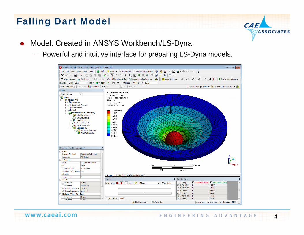
Model: Created in ANSYS Workbench/LS-Dyna Model: Created in ANSYS Workbench/LS-Dyna— Powerful and intuitive interface for preparing LS-Dyna models.
4
Falling Dart Model
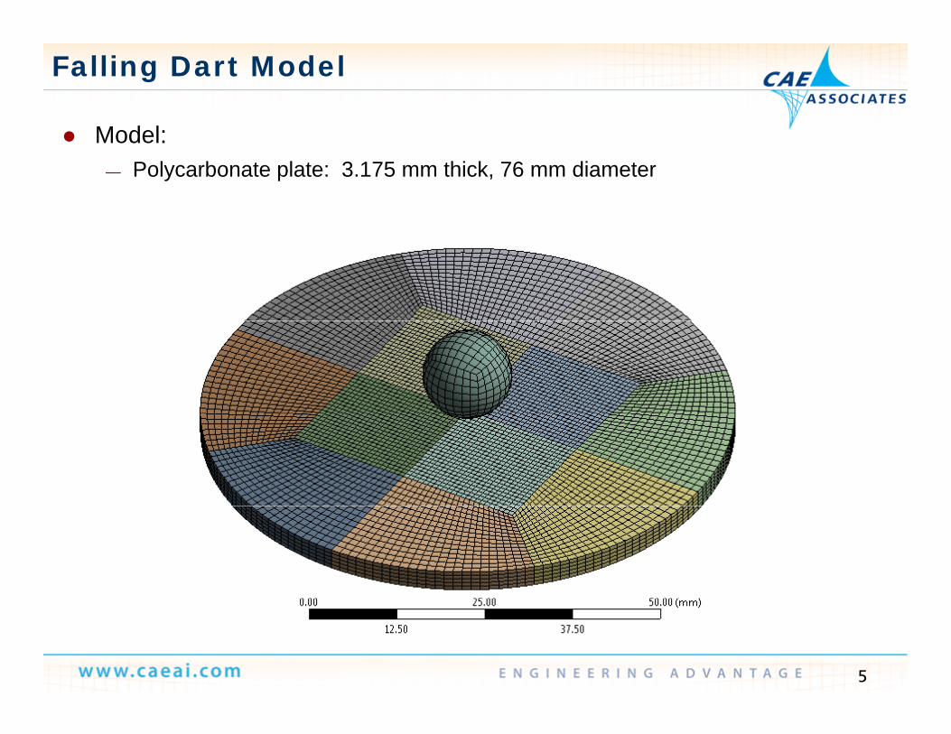
Model: Model:— Polycarbonate plate: 3.175 mm thick, 76 mm diameter
5
Falling Dart Model
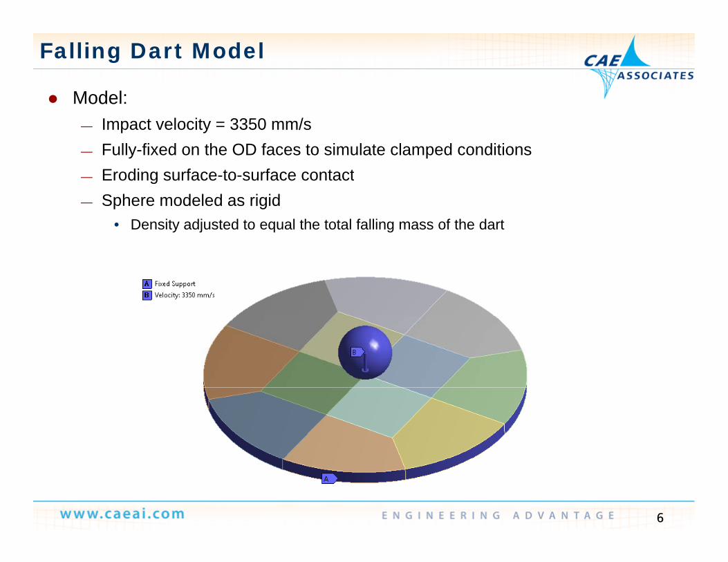
Model:ode— Impact velocity = 3350 mm/s— Fully-fixed on the OD faces to simulate clamped conditions
Eroding surface to surface contact— Eroding surface-to-surface contact— Sphere modeled as rigid
• Density adjusted to equal the total falling mass of the dart
6
Falling Dart Model
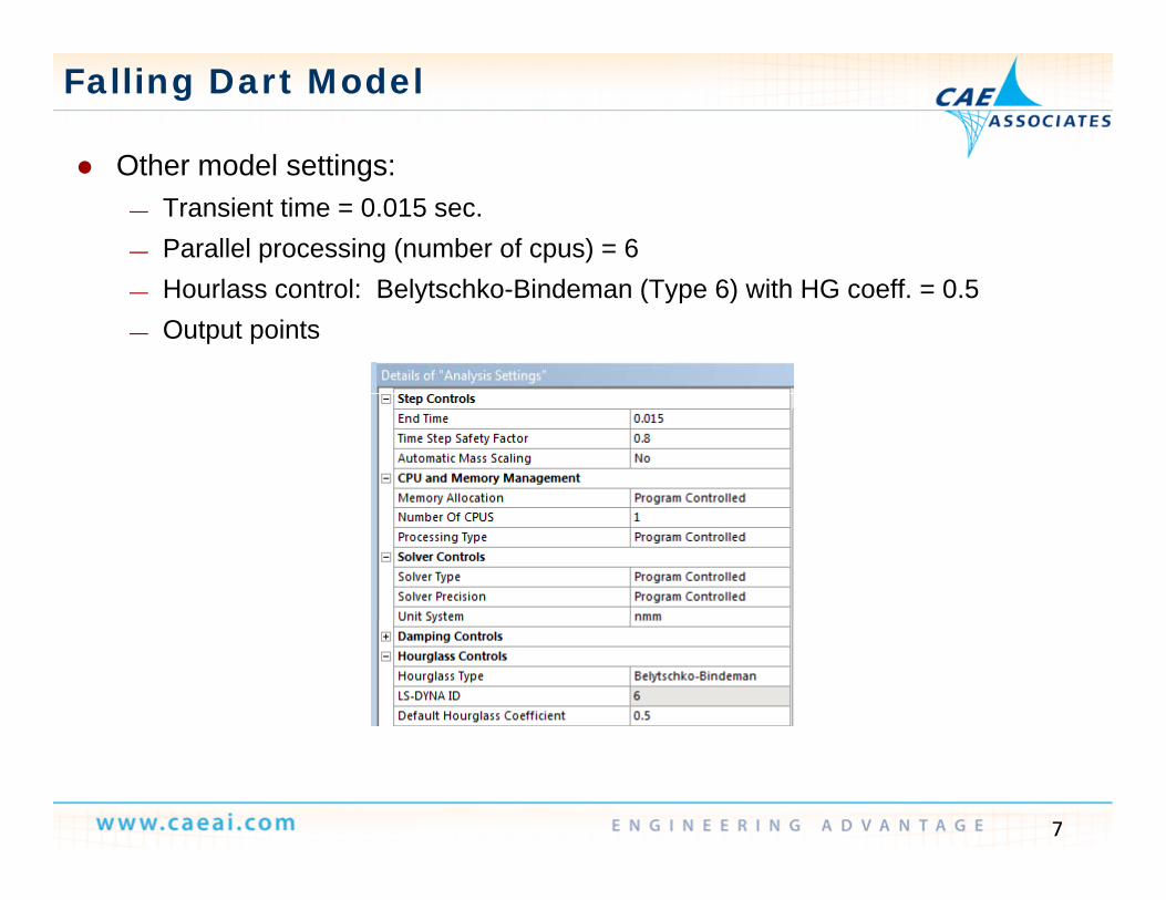
Other model settings: Other model settings:— Transient time = 0.015 sec.— Parallel processing (number of cpus) = 6
H l t l B l t hk Bi d (T 6) ith HG ff 0 5— Hourlass control: Belytschko-Bindeman (Type 6) with HG coeff. = 0.5— Output points
7
Material
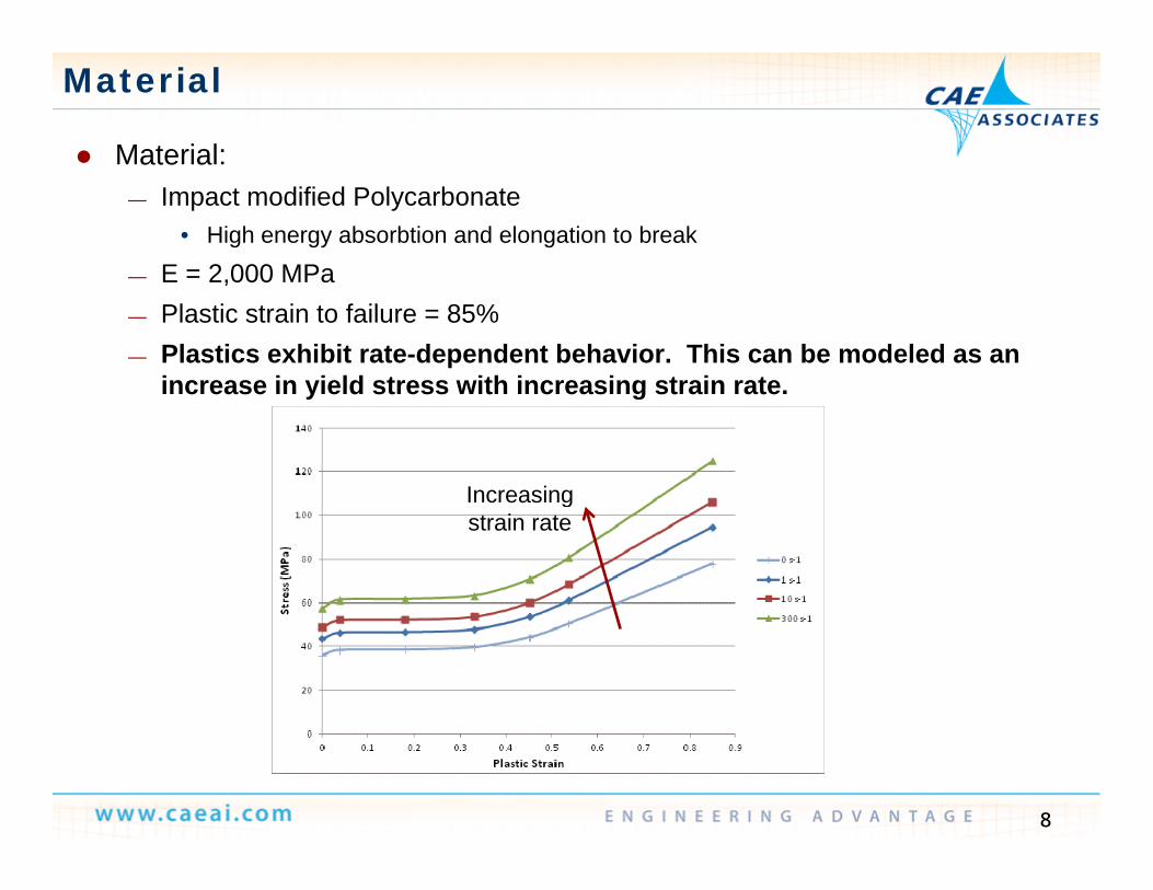
Material:ate a— Impact modified Polycarbonate
• High energy absorbtion and elongation to break
E = 2 000 MPa— E = 2,000 MPa— Plastic strain to failure = 85%— Plastics exhibit rate-dependent behavior. This can be modeled as an
increase in yield stress with increasing strain rateincrease in yield stress with increasing strain rate.
IncreasingIncreasing strain rate
8
Material Model
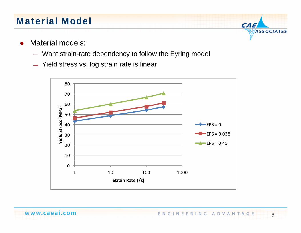
Material models: Material models: — Want strain-rate dependency to follow the Eyring model— Yield stress vs. log strain rate is linear
70
80
40
50
60
Stress (M
Pa)
EPS = 0
10
20
30
Yield S EPS = 0.038
EPS = 0.45
01 10 100 1000
Strain Rate (/s)
9
Material Model
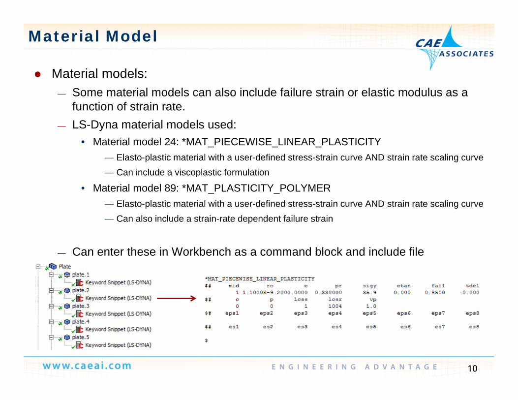
Material models: Material models:— Some material models can also include failure strain or elastic modulus as a
function of strain rate.LS Dyna material models used:— LS-Dyna material models used:
• Material model 24: *MAT_PIECEWISE_LINEAR_PLASTICITY— Elasto-plastic material with a user-defined stress-strain curve AND strain rate scaling curve— Can include a viscoplastic formulationCan include a viscoplastic formulation
• Material model 89: *MAT_PLASTICITY_POLYMER— Elasto-plastic material with a user-defined stress-strain curve AND strain rate scaling curve— Can also include a strain-rate dependent failure strain
— Can enter these in Workbench as a command block and include file
10
Material Model
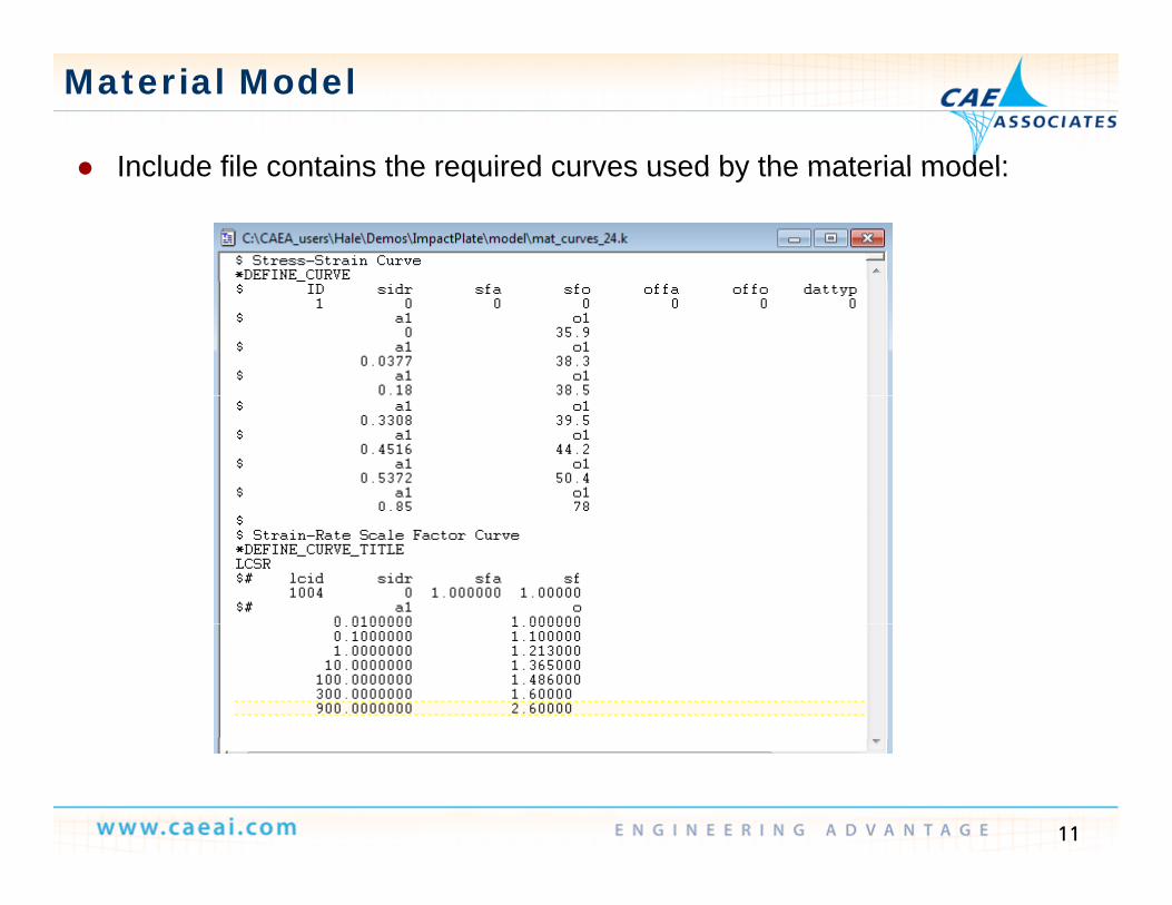
Include file contains the required curves used by the material model: Include file contains the required curves used by the material model:
11
Results
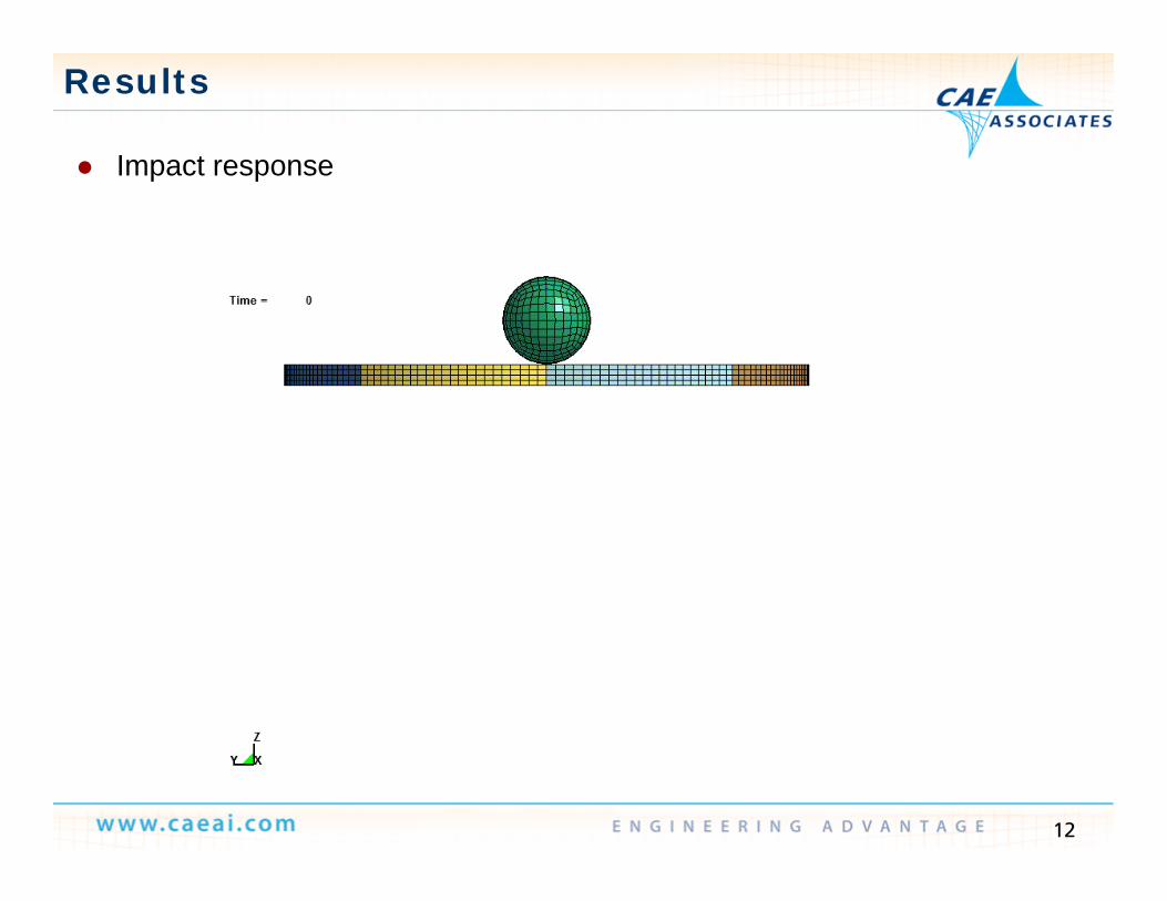
Impact response Impact response
12
Results
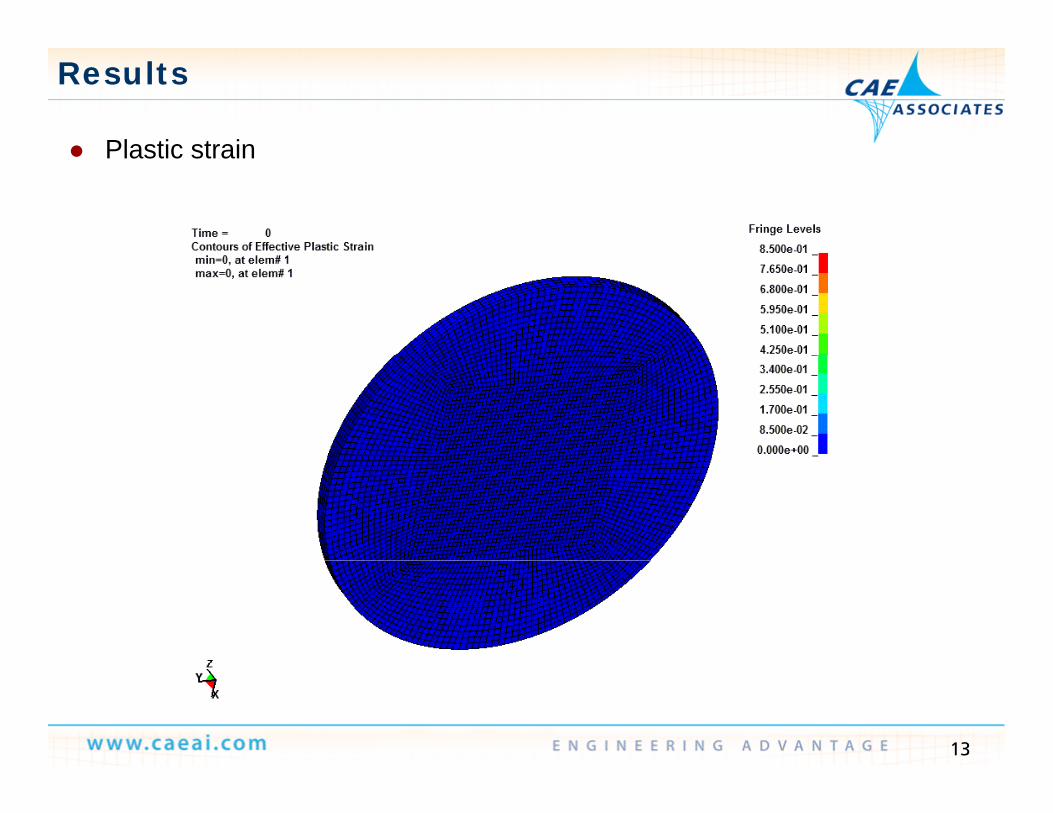
Plastic strain Plastic strain
13
Results
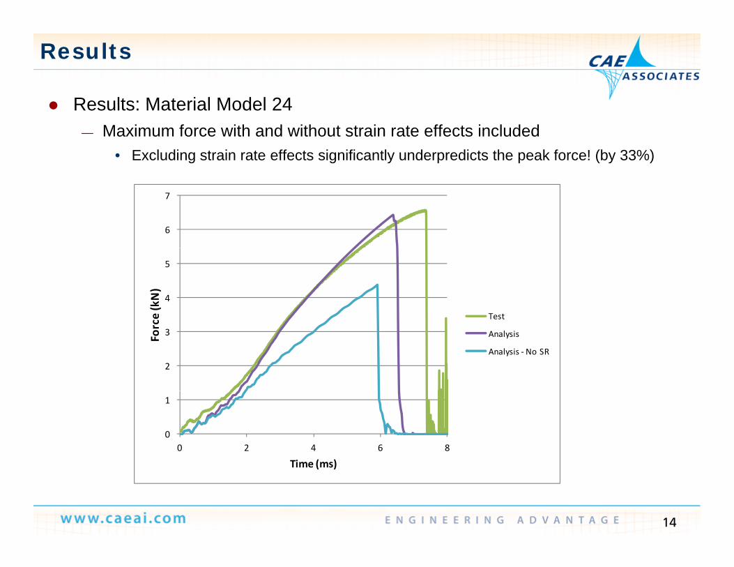
Results: Material Model 24 Results: Material Model 24— Maximum force with and without strain rate effects included
• Excluding strain rate effects significantly underpredicts the peak force! (by 33%)
6
7
4
5
e (kN)
Test
2
3Forc
Analysis
Analysis ‐ No SR
0
1
0 2 4 6 8
Time (ms)
14
Time (ms)
Results
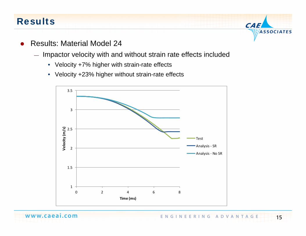
Results: Material Model 24 Results: Material Model 24— Impactor velocity with and without strain rate effects included
• Velocity +7% higher with strain-rate effectsVelocity +23% higher without strain rate effects• Velocity +23% higher without strain-rate effects
3.5
2.5
3
m/s)
2Velocity (m
Test
Analysis ‐ SR
Analysis ‐ No SR
1
1.5
0 2 4 6 8
15
0 2 4 6 8Time (ms)
Results
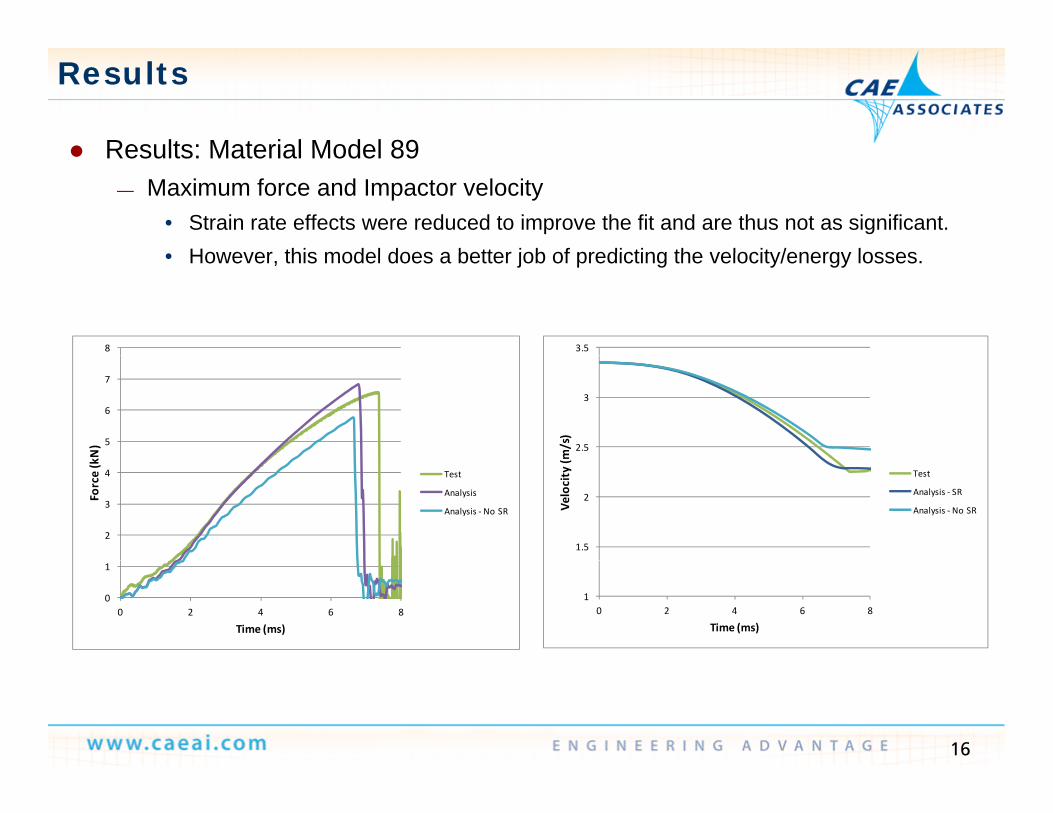
Results: Material Model 89 Results: Material Model 89— Maximum force and Impactor velocity
• Strain rate effects were reduced to improve the fit and are thus not as significant.However this model does a better job of predicting the velocity/energy losses• However, this model does a better job of predicting the velocity/energy losses.
8 3.5
5
6
7
N) 2.5
3
m/s)
2
3
4
Force (k
Test
Analysis
Analysis ‐No SR
1.5
2
Velocity (m
Test
Analysis ‐ SR
Analysis ‐ No SR
0
1
0 2 4 6 8
Time (ms)
10 2 4 6 8
Time (ms)
16
Conclusions
Material models exist in LS-Dyna that can accurately predict the complex response of a plastics under impact conditions, including general failure behavior.
— It is important to include strain rate sensitivity.— Material models can also account for strain rate sensitive failure.
ANSYS Workbench/LS-Dyna provides an efficient and intuitive interface y pfor preparing LS-Dyna models, including models with plastic parts requiring complex material models.
17
Top Related