


Languages
Pages
Legal

1
IMPORTANT:
Refer to www.extron.com for
the complete user guide and
installation instructions.
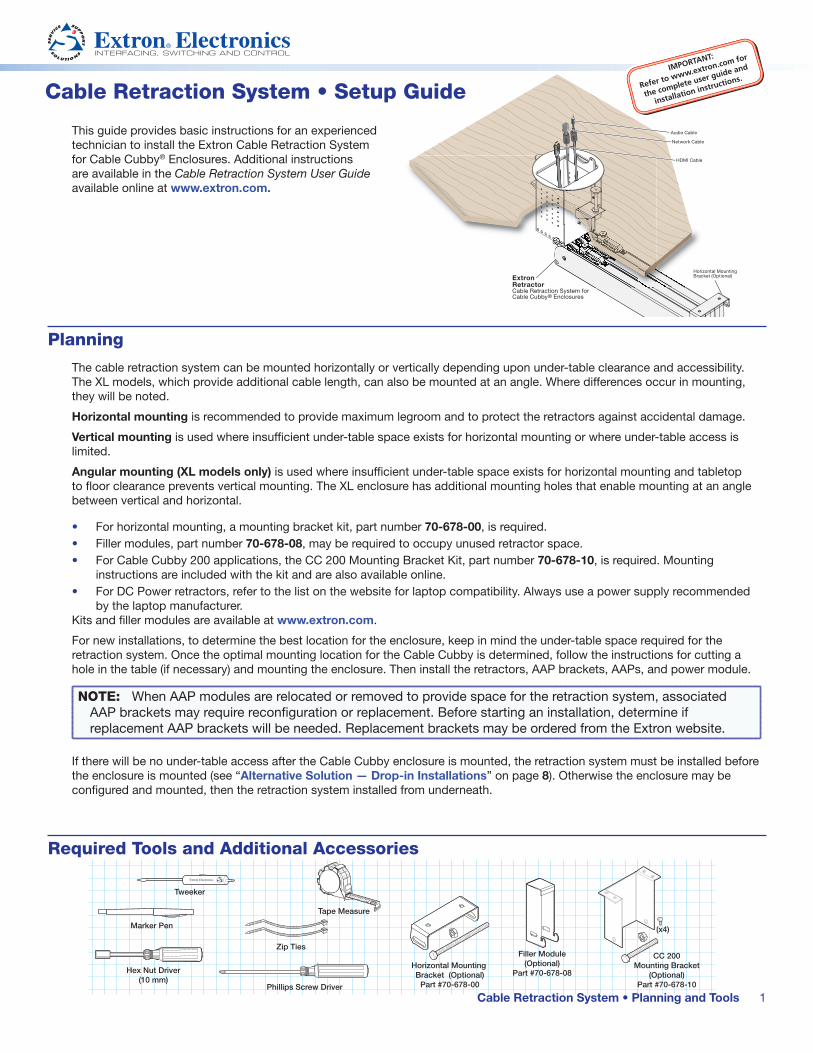
This guide provides basic instructions for an experienced technician to install the Extron Cable Retraction System for Cable Cubby® Enclosures. Additional instructions are available in the Cable Retraction System User Guide available online at www.extron.com.
Planning
The cable retraction system can be mounted horizontally or vertically depending upon under‑table clearance and accessibility. The XL models, which provide additional cable length, can also be mounted at an angle. Where differences occur in mounting, they will be noted.
Horizontal mounting is recommended to provide maximum legroom and to protect the retractors against accidental damage.
Vertical mounting is used where insufficient under‑table space exists for horizontal mounting or where under‑table access is limited.
Angular mounting (XL models only) is used where insufficient under‑table space exists for horizontal mounting and tabletop to floor clearance prevents vertical mounting. The XL enclosure has additional mounting holes that enable mounting at an angle between vertical and horizontal.
• For horizontal mounting, a mounting bracket kit, part number 70-678-00, is required.• Filler modules, part number 70-678-08, may be required to occupy unused retractor space. • For Cable Cubby 200 applications, the CC 200 Mounting Bracket Kit, part number 70-678-10, is required. Mounting
instructions are included with the kit and are also available online.• For DC Power retractors, refer to the list on the website for laptop compatibility. Always use a power supply recommended
by the laptop manufacturer.Kits and filler modules are available at www.extron.com.
For new installations, to determine the best location for the enclosure, keep in mind the under‑table space required for the retraction system. Once the optimal mounting location for the Cable Cubby is determined, follow the instructions for cutting a hole in the table (if necessary) and mounting the enclosure. Then install the retractors, AAP brackets, AAPs, and power module.
NOTE: When AAP modules are relocated or removed to provide space for the retraction system, associated AAP brackets may require reconfiguration or replacement. Before starting an installation, determine if replacement AAP brackets will be needed. Replacement brackets may be ordered from the Extron website.
If there will be no under‑table access after the Cable Cubby enclosure is mounted, the retraction system must be installed before the enclosure is mounted (see “Alternative Solution — Drop-in Installations” on page 8). Otherwise the enclosure may be configured and mounted, then the retraction system installed from underneath.
Required Tools and Additional Accessories
Cable Retraction System • Setup Guide
Cable Retraction System • Planning and Tools
Horizontal Mounting Bracket (Optional)
Part #70-678-00
Filler Module(Optional)
Part #70-678-08
CC 200Mounting Bracket
(Optional)Part #70-678-10
Tape Measure
Hex Nut Driver(10 mm)
Phillips Screw Driver
Zip Ties
Marker Pen
Tweeker
(x4)
HDMI Cable
Audio Cable
Network Cable
Extron RetractorCable Retraction System for Cable Cubby® Enclosures
Mounted inHorizontal Positionin Cable Cubby 300C
Horizontal Mounting Bracket (Optional)
2
Cable Retraction System • Setup Guide (Continued)
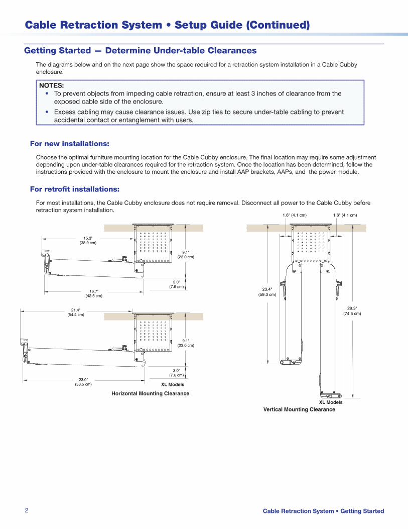
Getting Started — Determine Under-table Clearances
The diagrams below and on the next page show the space required for a retraction system installation in a Cable Cubby enclosure.
NOTES: • To prevent objects from impeding cable retraction, ensure at least 3 inches of clearance from the
exposed cable side of the enclosure.
• Excess cabling may cause clearance issues. Use zip ties to secure under‑table cabling to prevent accidental contact or entanglement with users.
For new installations:
Choose the optimal furniture mounting location for the Cable Cubby enclosure. The final location may require some adjustment depending upon under‑table clearances required for the retraction system. Once the location has been determined, follow the instructions provided with the enclosure to mount the enclosure and install AAP brackets, AAPs, and the power module.
For retrofit installations:
For most installations, the Cable Cubby enclosure does not require removal. Disconnect all power to the Cable Cubby before retraction system installation.
Cable Retraction System • Getting Started
1.6" (4.1 cm)
23.4"(59.3 cm)
1.6" (4.1 cm)
29.3"(74.5 cm)
Vertical Mounting ClearanceXL Models
Horizontal Mounting Clearance
XL Models
9.1"(23.0 cm)
15.3"(38.9 cm)
16.7"(42.5 cm)
3.0"(7.6 cm)
9.1"(23.0 cm)
21.4"(54.4 cm)
23.0"(58.5 cm)
3.0"(7.6 cm)
3
Product Category
Top View
HorizontalBracket
UNSWITCHED
100-240V/ 5AMAX
UNSWITCHED
US
P H
UB
4 AA
P
AC
TIV
ITY
100-240V/ 5AMAX
All installations (Except Drop-In):
The retraction system can be mounted from below the Cable Cubby enclosure.
Horizontal Mounting: Be certain the horizontal mounting bracket can be fastened under the table or on a table support without bending the pulley system or forcing it from perpendicular with the enclosure (see the Top View diagram below, left).
Vertical Mounting: Ensure the retraction system will hang freely without touching the floor and is not obstructed by anything under the table. The standard system requires about 24 inches (61 cm) and the XL systems require about 30 inches (76.2 cm) from the top of the furniture to clear the floor.
Angular Mounting (XL models only): For installations where the tabletop is less than 30 inches from the floor, the XL retractor system is too long for vertical mounting and there may not be adequate under‑table clearance for horizontal mounting. An additional mounting hole has been provided for these installations that allow the retractor system to install at an angle providing extra floor clearance (see diagram below, right).
29.3"(74.5 cm)28.0"
(71.1 cm)
Floor
27.7"(70.3 cm)
10.4"(26.4 cm)
25
1.6"(4.1 cm)
XL Models Vertical Clearance - Angular and Vertical Mounting
For minimum table height requirements of 28 inches (71 cm) specified by ADA Section 4.32.
4
Cable Retraction System • Setup Guide (Continued)
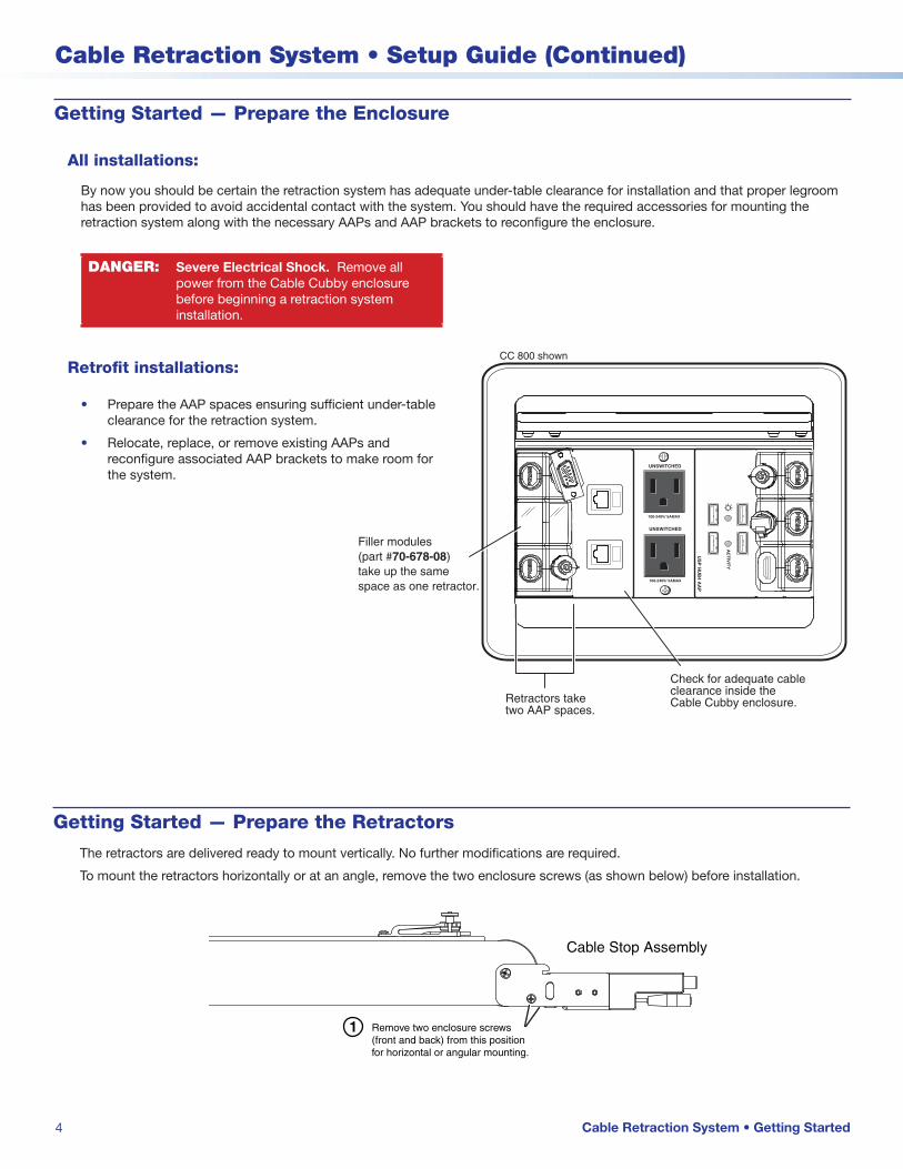
Getting Started — Prepare the Enclosure
All installations:
By now you should be certain the retraction system has adequate under‑table clearance for installation and that proper legroom has been provided to avoid accidental contact with the system. You should have the required accessories for mounting the retraction system along with the necessary AAPs and AAP brackets to reconfigure the enclosure.
DANGER: Severe Electrical Shock. Remove all power from the Cable Cubby enclosure before beginning a retraction system installation.
Retrofit installations:
• Prepare the AAP spaces ensuring sufficient under‑table clearance for the retraction system.
• Relocate, replace, or remove existing AAPs and reconfigure associated AAP brackets to make room for the system.
Getting Started — Prepare the Retractors
The retractors are delivered ready to mount vertically. No further modifications are required.
To mount the retractors horizontally or at an angle, remove the two enclosure screws (as shown below) before installation.
UNSWITCHED
100-240V/ 5AMAX
UNSWITCHED
US
P H
UB
4 AA
P
AC
TIV
ITY
100-240V/ 5AMAX
Check for adequate cable clearance inside theCable Cubby enclosure.Retractors take
two AAP spaces.
Filler modules (part #70-678-08)take up the same space as one retractor.
CC 800 shown
Cable Retraction System • Getting Started
Remove two enclosure screws (front and back) from this position for horizontal or angular mounting.
Install two enclosure screws (front and back) in angularmounting location.
1
2
3
Cable Stop Assembly
Enclosure
Move cable stop assemblyupward until the angularmounting hole is visible.

5
Product Category
Cable Retraction System • Getting Started
Remove two enclosure screws (front and back) from this position for horizontal or angular (XL) mounting.
Enclosure screws (front and back) removed.
Remove two enclosure screws (front and back) from this position for horizontal or angular mounting.
Install two enclosure screws (front and back) in angularmounting location.
1
2
3
Cable Stop Assembly
Enclosure
Move cable stop assemblyupward until the angularmounting hole is visible.
To mount the retractor horizontally:
To mount XL model retractors in an angled position for increased under-table clearance:
6
Cable Retraction System • Setup Guide (Continued)
Cable Retraction System • Installation
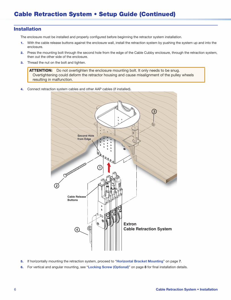
Installation
The enclosure must be installed and properly configured before beginning the retractor system installation.
1. With the cable release buttons against the enclosure wall, install the retraction system by pushing the system up and into the enclosure.
2. Press the mounting bolt through the second hole from the edge of the Cable Cubby enclosure, through the retraction system, then out the other side of the enclosure.
3. Thread the nut on the bolt and tighten.
ATTENTION: Do not overtighten the enclosure mounting bolt. It only needs to be snug. Overtightening could deform the retractor housing and cause misalignment of the pulley wheels resulting in malfunction.
4. Connect retraction system cables and other AAP cables (if installed).
ExtronCable Retraction Systemd
a
Cable ReleaseButtons
b
c
Second Holefrom EdgeSecond Holefrom Edge
5. If horizontally mounting the retraction system, proceed to “Horizontal Bracket Mounting” on page 7.
6. For vertical and angular mounting, see “Locking Screw (Optional)” on page 8 for final installation details.

7
Product Category
Horizontal Bracket Mounting
Trace aroundbracket perimeter.
Mounted inHorizontal Position
4. Lower the assembly and remove the horizontal bracket from the retractors.
5. Position the bracket inside the lines drawn in step 3 and fasten with the supplied screws.
ATTENTION: Ensure the supplied screws do not pierce through the top of the table. If necessary, use appropriate screws based on the table material and thickness.
6. Raise the retraction system up into the installed bracket, run the bolt through the bracket and end caps, and secure with the supplied nut.
2. Raise the retractors with attached bracket to the desired mounting location.
NOTE: Be certain the system is perpendicular to the enclosure (see the “Top View” diagram on page 2) to prevent binding of the pulley system.
3. Ensure the bracket is flush with surface and trace a line around the bracket perimeter.
Horizontal Bracket
Mounting Holes
Horizontal Mounting Bolt
End Caps
Slotted Hole
NOTE: For vertical mounting, see “Locking Screw (Optional)” on page 8.
For horizontal mounting, the horizontal mounting bracket (part number 70-678-00) must be used. The slotted bolt holes allow for tolerance in placing the bracket.
To ensure accuracy follow these procedures:
1. Attach the horizontal mounting bracket to the retractor end caps using the provided bolt and nut.
TIP: Hand tighten the nut enough to keep the bracket from easily moving. The bolt and nut will be removed later.
Cable Retraction System • Horizontal Bracket Mounting
ATTENTION: Do not overtighten the horizontal mounting nut. It only needs to be snug. Overtightening could deform the end caps and cause misalignment of the system resulting in poor cable extension and retraction.
8
Cable Retraction System • Setup Guide (Continued)
Alternative Solution — Drop-in Installations
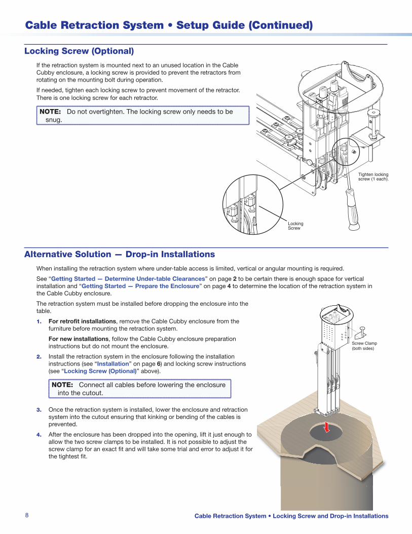
When installing the retraction system where under‑table access is limited, vertical or angular mounting is required.
See “Getting Started — Determine Under-table Clearances” on page 2 to be certain there is enough space for vertical installation and “Getting Started — Prepare the Enclosure” on page 4 to determine the location of the retraction system in the Cable Cubby enclosure.
The retraction system must be installed before dropping the enclosure into the table.
1. For retrofit installations, remove the Cable Cubby enclosure from the furniture before mounting the retraction system.
For new installations, follow the Cable Cubby enclosure preparation instructions but do not mount the enclosure.
2. Install the retraction system in the enclosure following the installation instructions (see “Installation” on page 6) and locking screw instructions (see “Locking Screw (Optional)” above).
NOTE: Connect all cables before lowering the enclosure into the cutout.
3. Once the retraction system is installed, lower the enclosure and retraction system into the cutout ensuring that kinking or bending of the cables is prevented.
4. After the enclosure has been dropped into the opening, lift it just enough to allow the two screw clamps to be installed. It is not possible to adjust the screw clamp for an exact fit and will take some trial and error to adjust it for the tightest fit.
Screw Clamp(both sides)
Locking Screw (Optional)
If the retraction system is mounted next to an unused location in the Cable Cubby enclosure, a locking screw is provided to prevent the retractors from rotating on the mounting bolt during operation.
If needed, tighten each locking screw to prevent movement of the retractor. There is one locking screw for each retractor.
NOTE: Do not overtighten. The locking screw only needs to be snug.
Tighten lockingscrew (1 each).
LockingScrew
Cable Retraction System • Locking Screw and Drop-in Installations
9
Product Category
Cable Retraction System • Retractor Operation
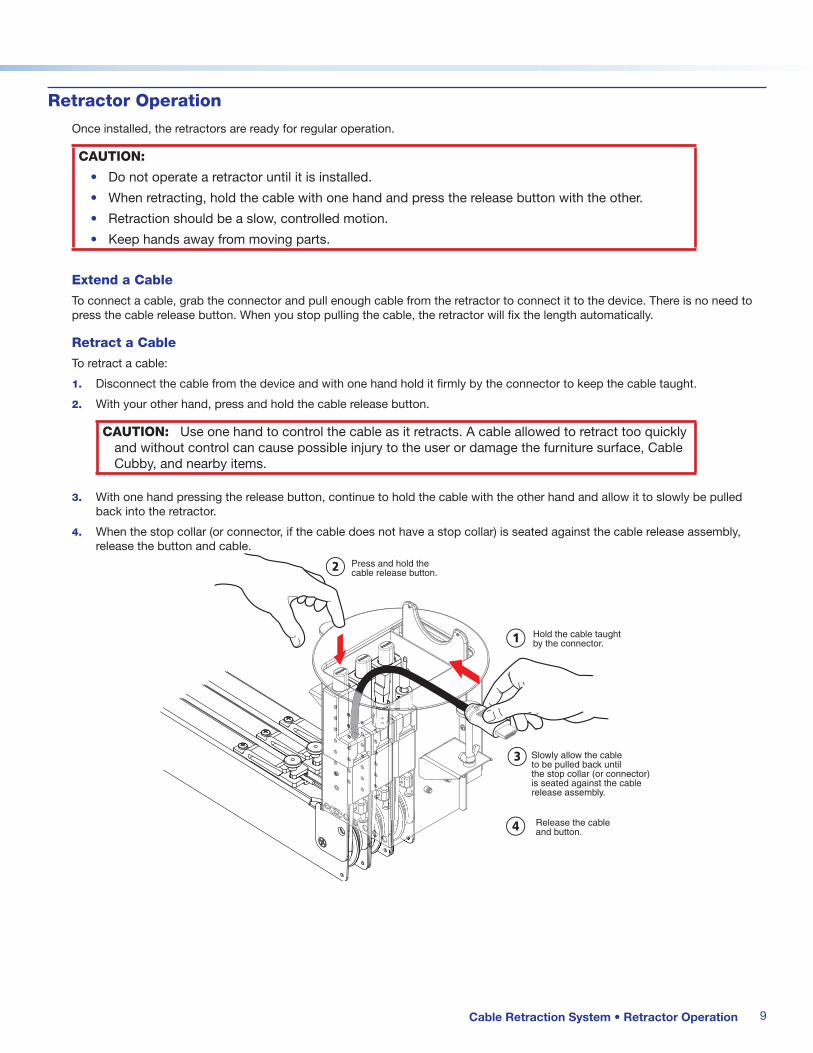
Retractor Operation
Once installed, the retractors are ready for regular operation.
CAUTION:
• Do not operate a retractor until it is installed.
• When retracting, hold the cable with one hand and press the release button with the other.
• Retraction should be a slow, controlled motion.
• Keep hands away from moving parts.
Extend a Cable
To connect a cable, grab the connector and pull enough cable from the retractor to connect it to the device. There is no need to press the cable release button. When you stop pulling the cable, the retractor will fix the length automatically.
Retract a Cable
To retract a cable:
1. Disconnect the cable from the device and with one hand hold it firmly by the connector to keep the cable taught.
2. With your other hand, press and hold the cable release button.
CAUTION: Use one hand to control the cable as it retracts. A cable allowed to retract too quickly and without control can cause possible injury to the user or damage the furniture surface, Cable Cubby, and nearby items.
3. With one hand pressing the release button, continue to hold the cable with the other hand and allow it to slowly be pulled back into the retractor.
4. When the stop collar (or connector, if the cable does not have a stop collar) is seated against the cable release assembly, release the button and cable.
1
2
3
4
Hold the cable taughtby the connector.
Press and hold the cable release button.
Slowly allow the cableto be pulled back untilthe stop collar (or connector)is seated against the cable release assembly.
Release the cableand button.
Planning (page 1)
� Ensure there is adequate space available in the Cable Cubby enclosure.
� Obtain the mounting brackets and accessories necessary for the application.
� If reconfiguration of the Cable Cubby enclosure is required, obtain the necessary AAP brackets.
� If necessary, obtain filler modules to occupy unused retractor space in the enclosure.
� Gather tools needed for installation.
Determine Under-table Clearances (page 2-3)
� For new installations, choose the optimal furniture mounting location.
� Choose retractor orientation:
• Horizontal mounting: Ensure horizontal bracket location is adequate.
• Vertical mounting: Ensure the retraction system hangs freely.
• Angular mounting (XL): Use angular mounting where vertical mounting is desired but the tabletop to floor distance is less than 30 inches.
� For retrofit installations, disconnect all power to the Cable Cubby.
Prepare the Cable Cubby Enclosure (page 4)
� Determine the enclosure mounting location for the retraction system.
� Relocate or remove existing AAPs and AAP brackets to clear space for the retraction system.
Prepare the Retractors (page 4-5)
� To mount the retractors horizontally or at an angle, remove the two retractor enclosure screws.
Install the Retractors (pages 6-8)
� Push the retraction system up and into the Cable Cubby enclosure and fasten with mounting bolt and nut (page 6).
� Connect all retraction system cables and other AAP cables (page 6).
� For horizontal mounting, determine the bracket mounting location and install the bracket (page 7).
� Tighten the locking screws (optional) (page 8).
Quick Installation Checklist
Under-table Connections, Maintenance, and Adjustments
ATTENTION:
• Each Extron retractor model is designed with custom‑made cable and a unique matching spring that work together to maintain cable signal integrity and preserve consistent cable retraction pull force over the life of the product. Alterations to the retractor will cause premature failure of the retractor system and cables.
• Modifications to the Retractor System are prohibited and will void the Extron warranty for this product. Consult your Sales representative for more information.
For normal maintenance, refer to “Maintenance and Adjustments” in the user guide.
If the cable does not retract completely into the retractor, see the “Pulley System Adjustments” section of the user guide.
Extron Headquarters+800.633.9876 Inside USA/Canada Only
Extron USA - West Extron USA - East+1.714.491.1500 +1.919.850.1000
+1.714.491.1517 FAX +1.919.850.1001 FAX
Extron Europe+800.3987.6673
Inside Europe Only
+31.33.453.4040
+31.33.453.4050 FAX
Extron Asia+800.7339.8766
Inside Asia Only
+65.6383.4400
+65.6383.4664 FAX
Extron Japan
+81.3.3511.7655
+81.3.3511.7656 FAX
Extron China+4000.EXTRON +4000.398766
Inside China Only
+86.21.3760.1568
+86.21.3760.1566 FAX
Extron Middle East
+971.4.2991800
+971.4.2991880 FAX
Extron Korea
+82.2.3444.1571
+82.2.3444.1575 FAX
Extron India1800.3070.3777
Inside India Only
+91.80.3055.3777
+91.80.3055.3737 FAX
© 2012 Extron Electronics All rights reserved. All trademarks mentioned are the property of their respective owners. www.extron.com 68-1784-50 Rev C 09 12
Top Related