


Languages
Pages
Legal


Building a Secure Short Duration Transaction
Network
A thesis submitted in partial fulfilment of the
requirements for the Degree
of Master of Science in Computer Science
in the University of Canterbury
by Andrew Gin
University of Canterbury
2007
Abstract
The objective of this project was to design and test a secure IP-based ar-
chitecture suitable for short duration transactions. This included the devel-
opment of a prototype test-bed in which various operating scenarios (such as
cryptographic options, various IP-based architectures and fault tolerance) were
demonstrated. A solution based on SIP secured with TLS was tested on two IP
based architectures. Total time, CPU time and heap usage was measured for
each architecture and encryption scheme to examine the viability of such a solu-
tion. The results showed that the proposed solution stack was able to complete
transactions in reasonable time and was able to recover from transaction proces-
sor failure. This research has demonstrated a possible architecture and protocol
stack suitable for IP-based transaction networks. The benefits of an IP-based
transaction network include reduced operating costs for network providers and
clients, as shared IP infrastructure is used, instead of maintaining a separate IP
and X.25 network.
Acknowledgements
I would like to thank my supervisor, Associate Professor Ray Hunt for supervis-
ing my project and Peter Chappell of Telecom for the invaluable guidance and
ideas. I would also like to thank Dr Andy Cockburn, for answering my questions
about the statistical analysis. Many thanks go to M. Ranganathan and Jeroen
van Bemmel of the JAIN-SIP mailing list, for answering my questions about
the JAIN-SIP library. Thanks also to Bogdan-Andrei Iancu of the OpenSER
mailing list for answering my questions about setting up the SIP server. I would
like to thank the BrainTrust II: Taher, Jason, Jay, Nancy, Natashka, Pramudi,
Anna and Kon. I would also like to extend my thanks to the fire support crew:
Norman Lee, Ray Hidayat and Pik. Your belief in me kept me going through
the worst days of the ‘task’. I’d also like to Grant “Grant” Evans for help-
ing me make ‘millions’, Adrian “AlJardino” Clark and Robert “rogerthecamel”
Grant for sticking it out with me through University and Kay Huang for being
a good friend and helping me create the awesomest sacrifice to lay on the altar
of Conquest! Finally I’d like to thank my friends and family for being there for
me.
i
Contents
1 Introduction 1
1.1 Research Goals . . . . . . . . . . . . . . . . . . . . . . . . . . . . 3
2 Telecom Transaction Service 5
2.1 Network Access Controller (NAC) . . . . . . . . . . . . . . . . . 6
2.2 Network Management System (NMS) . . . . . . . . . . . . . . . 7
2.3 Security . . . . . . . . . . . . . . . . . . . . . . . . . . . . . . . . 7
2.4 Procedure . . . . . . . . . . . . . . . . . . . . . . . . . . . . . . . 8
2.5 Previous Approaches . . . . . . . . . . . . . . . . . . . . . . . . . 10
2.6 Requirements . . . . . . . . . . . . . . . . . . . . . . . . . . . . . 12
3 Candidate Protocols 14
3.1 Transmission Control Protocol (TCP) - RFC 793 . . . . . . . . . 14
3.2 User Datagram Protocol (UDP) - RFC 768 . . . . . . . . . . . . 15
3.3 Transaction TCP (T/TCP) - RFC 1644 . . . . . . . . . . . . . . 15
3.3.1 Bypassing the 3-way handshake . . . . . . . . . . . . . . . 16
3.3.2 Truncation of the TIME WAIT state . . . . . . . . . . . . 18
3.3.3 Security Vulnerabilities . . . . . . . . . . . . . . . . . . . 22
3.3.4 Implementations and Development . . . . . . . . . . . . . 25
3.3.5 Summary . . . . . . . . . . . . . . . . . . . . . . . . . . . 26
3.4 Stream Control Transmission Protocol (SCTP) - RFC 2960 . . . 27
3.4.1 Association Initiation . . . . . . . . . . . . . . . . . . . . 33
3.4.2 Association Shutdown . . . . . . . . . . . . . . . . . . . . 34
3.4.3 Implementations and Development . . . . . . . . . . . . . 35
3.4.4 Summary . . . . . . . . . . . . . . . . . . . . . . . . . . . 37
3.5 Quick Transaction Protocol (QTP) . . . . . . . . . . . . . . . . . 37
3.5.1 QTP Startup . . . . . . . . . . . . . . . . . . . . . . . . . 39
3.5.2 Session Startup (Call Request) . . . . . . . . . . . . . . . 40
3.5.3 Data Transfer . . . . . . . . . . . . . . . . . . . . . . . . . 40
ii
3.5.4 Session Shutdown (Call Clear) . . . . . . . . . . . . . . . 41
3.5.5 Implementation and Development . . . . . . . . . . . . . 41
3.5.6 Summary . . . . . . . . . . . . . . . . . . . . . . . . . . . 42
3.6 Session Initiation Protocol (SIP) - RFC 3261 . . . . . . . . . . . 43
3.6.1 Session Initiation . . . . . . . . . . . . . . . . . . . . . . . 45
3.6.2 Session Modification . . . . . . . . . . . . . . . . . . . . . 47
3.6.3 Session Termination . . . . . . . . . . . . . . . . . . . . . 48
3.6.4 Implementation and Development . . . . . . . . . . . . . 48
3.6.5 Summary . . . . . . . . . . . . . . . . . . . . . . . . . . . 51
3.7 Simple Object Access Protocol - SOAP . . . . . . . . . . . . . . 51
3.8 Versatile Message Transaction Protocol (VMTP) - RFC 1045 . . 53
3.9 Xpress Transfer Protocol (XTP) . . . . . . . . . . . . . . . . . . 54
4 Security Candidates 56
4.1 Secure Shell (SSH) - RFC 4251 . . . . . . . . . . . . . . . . . . . 56
4.1.1 Connection Setup . . . . . . . . . . . . . . . . . . . . . . 59
4.1.2 Connection Closing . . . . . . . . . . . . . . . . . . . . . . 64
4.1.3 Advantages . . . . . . . . . . . . . . . . . . . . . . . . . . 64
4.1.4 Drawbacks . . . . . . . . . . . . . . . . . . . . . . . . . . 65
4.1.5 Implementations and Development . . . . . . . . . . . . . 66
4.1.6 Summary . . . . . . . . . . . . . . . . . . . . . . . . . . . 67
4.2 IP Security (IPsec) - RFC 4301 . . . . . . . . . . . . . . . . . . . 67
4.2.1 Establishing a Security Association (SA) . . . . . . . . . . 68
4.2.2 Deleting a Security Association (SA) . . . . . . . . . . . . 71
4.2.3 Advantages . . . . . . . . . . . . . . . . . . . . . . . . . . 72
4.2.4 Drawbacks . . . . . . . . . . . . . . . . . . . . . . . . . . 73
4.2.5 Implementations and development . . . . . . . . . . . . . 76
4.2.6 Summary . . . . . . . . . . . . . . . . . . . . . . . . . . . 76
4.3 Transport Layer Security (TLS) - RFC 4346 . . . . . . . . . . . . 77
4.3.1 Connection Setup . . . . . . . . . . . . . . . . . . . . . . 78
4.3.2 Connection Closing . . . . . . . . . . . . . . . . . . . . . . 82
4.3.3 Implementations and Development . . . . . . . . . . . . . 82
4.3.4 Advantages . . . . . . . . . . . . . . . . . . . . . . . . . . 87
4.3.5 Drawbacks . . . . . . . . . . . . . . . . . . . . . . . . . . 89
4.3.6 Summary . . . . . . . . . . . . . . . . . . . . . . . . . . . 89
5 Architectural Analysis 91
5.1 Open Internet . . . . . . . . . . . . . . . . . . . . . . . . . . . . . 91
5.1.1 Advantages . . . . . . . . . . . . . . . . . . . . . . . . . . 92
iii
5.1.2 Drawbacks . . . . . . . . . . . . . . . . . . . . . . . . . . 92
5.2 Controlled IP PSTN . . . . . . . . . . . . . . . . . . . . . . . . . 93
5.2.1 Advantages . . . . . . . . . . . . . . . . . . . . . . . . . . 95
5.2.2 Disadvantages . . . . . . . . . . . . . . . . . . . . . . . . . 95
5.3 Conclusion . . . . . . . . . . . . . . . . . . . . . . . . . . . . . . 96
5.4 Architectural Options . . . . . . . . . . . . . . . . . . . . . . . . 97
5.4.1 IP PSTN Solution . . . . . . . . . . . . . . . . . . . . . . 97
5.4.2 Open Internet Solution . . . . . . . . . . . . . . . . . . . 103
5.4.3 Conclusion . . . . . . . . . . . . . . . . . . . . . . . . . . 107
6 Architectural Implementation 109
6.1 The Client . . . . . . . . . . . . . . . . . . . . . . . . . . . . . . . 110
6.2 The Concentrator . . . . . . . . . . . . . . . . . . . . . . . . . . . 111
6.3 The Transaction Processor . . . . . . . . . . . . . . . . . . . . . . 112
6.4 The SIP Server . . . . . . . . . . . . . . . . . . . . . . . . . . . . 113
6.5 IP PSTN Network . . . . . . . . . . . . . . . . . . . . . . . . . . 113
6.6 Open Internet . . . . . . . . . . . . . . . . . . . . . . . . . . . . . 117
7 Architectural Validation and Evaluation 120
7.1 Network Setup . . . . . . . . . . . . . . . . . . . . . . . . . . . . 120
7.2 Experimental Design . . . . . . . . . . . . . . . . . . . . . . . . . 120
7.2.1 Single Transaction Measurements . . . . . . . . . . . . . . 121
7.2.2 Multiple Transaction Measurements . . . . . . . . . . . . 122
7.2.3 Impact of Concentrators . . . . . . . . . . . . . . . . . . . 123
7.2.4 Recovery Time . . . . . . . . . . . . . . . . . . . . . . . . 123
8 Results and Discussion 125
8.1 Single Transaction . . . . . . . . . . . . . . . . . . . . . . . . . . 125
8.2 Multiple Transactions . . . . . . . . . . . . . . . . . . . . . . . . 128
8.3 Impact of Concentrators . . . . . . . . . . . . . . . . . . . . . . . 131
8.4 Recovery Time . . . . . . . . . . . . . . . . . . . . . . . . . . . . 136
8.5 Discussion . . . . . . . . . . . . . . . . . . . . . . . . . . . . . . . 138
8.5.1 Single Transactions . . . . . . . . . . . . . . . . . . . . . . 139
8.5.2 Multiple Transactions . . . . . . . . . . . . . . . . . . . . 142
8.5.3 Impact of Concentrators . . . . . . . . . . . . . . . . . . . 143
8.5.4 Recovery Time . . . . . . . . . . . . . . . . . . . . . . . . 144
8.5.5 Limitations . . . . . . . . . . . . . . . . . . . . . . . . . . 145
9 Conclusions 147
iv

References 149
A Generating Certificates 160
v

Chapter 1
Introduction
Transaction networks are deployed in many scenarios for example: fire/burglar
alarms, remote monitoring/metering systems, airport check in systems and au-
tomated teller machines (ATMS). A transaction has the following properties
(from [28]):
• Asymmetrical Model: the two endpoints have distinct roles; one is a client
which initiates transactions, and the other is a server, which processes
requests.
• Half Duplex Transfers: it is unnecessary to send data in both directions
simultaneously.
• Short Duration: transactions last between 100s of milliseconds up to sev-
eral seconds, but never hours.
• Low Delay: latency is usually low.
• Few Data packets: typically two packets, a request and a response.
• Message Orientation: messages, rather than a stream of bytes, are trans-
ferred.
Mission critical transactions (such as medical alert systems and ATMs) may
have additional characteristics (from [117]):
• High Call Rates: some deployments involve a large number of clients con-
necting to a smaller number of servers.
• High peak to average load ratio: for example ATMs may average 20 trans-
actions per second for most of the year, but may increase to 200 during
the busiest day in December.
1
CHAPTER 1. INTRODUCTION 2
One visible application of transaction networks is Electronic Funds Transfer at
Point of Sale (EFTPOS). EFTPOS was launched in New Zealand in 1984 and
has since become a popular method for making payments. EFTPOS runs over
the Telecom Transaction Service (TTS) network. TTS is based on legacy pro-
tocols: High-Level Data Link Control in Normal Response Mode (HDLC NRM,
also known as Synchronous Data Link Control or SDLC) on the transaction
terminal side and X.25 on the bank switch delivery side. The transport layer
is AS2805.1, a connectionless datagram protocol. The AS2805 group of proto-
cols is a standard specifically designed for electronic funds transfers. AS2805
encompasses a transport protocol (.1), a financial messaging protocol (.2) and
message security, authentication, security and key management (.3-.6) among
others. AS2805.2 is an ISO 8583 message format, a specification for financial
messages used by payment cards.
TTS uses Public Switched Telephone Network (PSTN) dial up access for
sites with low transaction volumes and dedicated leased line access for loca-
tions with higher transaction volumes. In addition to transaction terminals and
transaction processors, TTS infrastructure is also comprised of concentrators
(to aggregate transactions) and Network Access Controllers (NACs). NACs
provide protocol conversion, proxying, concentration of transactions, routing
and network management functions.
TTS is based on protocols that have been superseded by IP based protocols.
IP is ubiquitous; many large organisations have deployed IP networks, while
broadband DSL and wireless access bring IP connectivity to small businesses
and residential users. Voice telephony is also migrating to IP as Voice over IP
(VoIP). Running multiple services over a shared IP infrastructure reduces costs
as providers no longer need to maintain and operate a dedicated, specialised net-
work that provides for only a single application. Thus, EFTPOS will eventually
need to be migrated to operate over IP.
Transaction terminals each need their own telephone line or leased line.
When IP is used, however, multiple terminals can share the same link. Line
rental costs can be reduced by connecting terminals to an existing DSL service
instead of providing each terminal with its own phone line. Adding a terminal
to an existing LAN or DSL service is also faster than adding an additional
telephone line at the merchant’s premises.
Broadband services are ‘always on’. Transaction terminals can take advan-
tage of this as no connection time is required. Broadband DSL speeds are also
at least several megabits per second in speed. This is sufficient to support
hundreds of transaction terminals in addition to existing uses of DSL such as
CHAPTER 1. INTRODUCTION 3
internet use and VoIP [17].
If the EFTPOS service can operate over IP, it opens up the potential to use
any medium which can carry IP, for example wireless broadband, GPRS and
CDMA. This creates the possibility for a mobile real time EFTPOS service, for
example in taxis and temporary stalls. Current mobile EFTPOS services are
batch processed offline (at the end of the day for example).
In addition to business drivers, such as reducing operational costs, for mi-
grating from legacy protocols to modern protocols, technical drivers exist as
well. As X.25 is progressively replaced with IP networks, X.25 skills will di-
minish, for example planning, configuring and maintenance. There is also the
potential reduction of vendor support. Furthermore, replacing X.25 infrastruc-
ture as hardware becomes obsolete, also becomes more expensive.
The newer protocols also improve on X.25. X.25 provides a robust, error free
link between two end points.1 X.25 buffers the entire frame, checks it for errors,
then forwards it to the next node. The cost of this error correction is a high
delay. While this has little effect for large transfers, it is noticeable with small
exchanges such as an EFTPOS transaction. This buffering behaviour increases
the memory required in X.25 hardware, also making it expensive.
X.25 is optimised for noisy links with high error rates. However, newer dig-
ital transmission media have improved in quality, making X.25’s robust error
correction unnecessary. The high latency as a consequence of this error correc-
tion also results in poor bandwidth utilisation; small packet and window sizes,
in addition to the latency, cause X.25 to lose its effectiveness when the line speed
is greater than 100kbps. Modern broadband speeds, even for residential users,
are typically much higher than this.
1.1 Research Goals
This research aims to define a generic IP based transaction protocol stack on
which to run a transaction oriented application. The current EFTPOS system
will be used as a benchmark system.
This project does not intend to define a new EFTPOS protocol, that is, a
replacement for AS2805, but rather define a new generic architecture that can
carry AS2805 or any other transaction oriented protocol.
The new architecture must at least have the same performance and charac-
teristics as the current benchmark EFTPOS system, but should be capable of
exceeding them. These characteristics include security, reliability, availability1http://www.sangoma.com/main/support/tutorials/x25
CHAPTER 1. INTRODUCTION 4
and transaction time.
This requires analysing potential messaging/transport and security proto-
cols which satisfy the requirements. From the candidate protocols, a protocol
stack can be assembled which forms the basis of possible architectures. The
architecture defined is not limited to an EFTPOS application; it is relevant to
any system that utilises short transactions.

Chapter 2
Telecom Transaction
Service
This section details an example of a current transaction network, the Tele-
com Transaction Service (TTS). TTS is used for the EFTPOS system in New
Zealand. Transaction terminals connect to transaction processors via Network
Access Controllers (NAC), as the topology in Figure 2.1 illustrates [66]. Transac-
tion terminals can send transactions in either front end or back end transaction
mode. Terminals in front end switching mode send transactions to processors
as designated by the card issuer. Thus, a terminal will send transactions to
several processors. Terminals in back end switching mode send all transactions,
regardless of card issuer, to a single processor. This transaction processor will
then either process the transaction itself or send it to the transaction processor
elected by the card issuer.
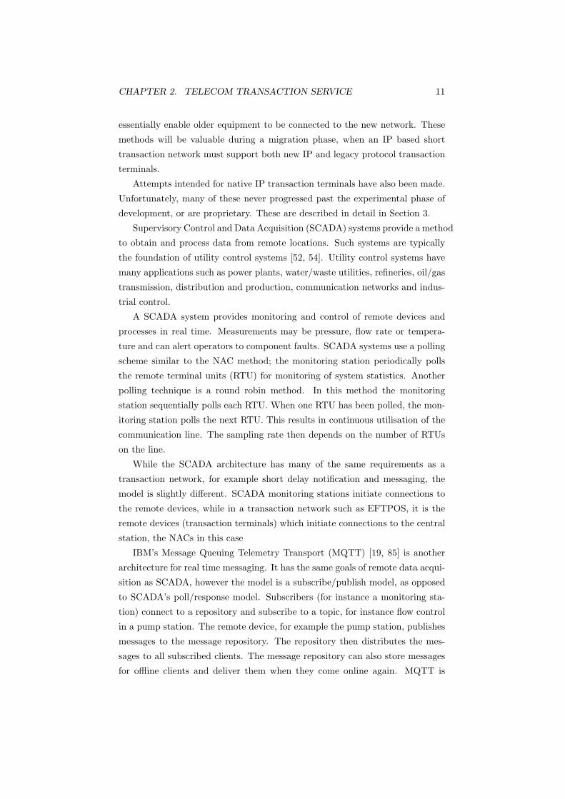
Figure 2.1: The Telecom Transaction Service (TTS) Toplogy.
5

CHAPTER 2. TELECOM TRANSACTION SERVICE 6
The protocol stack is in Figure 2.2. Transaction terminals use HDLC(NRM)/SDLC
as the Data Link/Network layer protocol to communicate with the NAC. The
NAC operates as the NRM primary station and the terminal as the NRM sec-
ondary station (that is, the NAC always polls the terminal). The NAC commu-
nicates with transaction processors via the TTS X.25 network. The transport
protocol AS2805.1 is used end to end from the transaction terminal to the trans-
action processor.
Figure 2.2: The current TTS protocol stack.
2.1 Network Access Controller (NAC)
NACs provide TTS access for transaction terminals. NACs also multiplex, route
and accumulate network statistics. NACs concentrate 16 or 32 connections onto
a single X.25 connection to the transaction processor. Multiplexing reduces the
processing load on the transaction processor, as fewer connections are dealt with.
The routing role enables transaction terminals to address different transaction
processors as required (explained in Section 2.4). Network statistics accumu-
lated for each terminal and X.25 port can be used by the Network Management
System for fault resolution and network planning.
Terminals connect to one of the NAC’s 16 or 32 connections in several ways:
Dial Up: This uses the PSTN to access the NAC. This is less reliable and
slower than a dedicated connection (the other three methods described
below), but allows widely distributed, low transaction volume terminals
to be concentrated on a small number of NAC ports. Terminals using
this access method are only visible during a transaction, which prevents
management of these terminals.
Single Drop: A single terminal can have a dedicated line for continuous access
to a single port on the NAC. This is intended for high volume locations

CHAPTER 2. TELECOM TRANSACTION SERVICE 7
which require high reliability and availability. Dedicated lines do not rely
on the PSTN; the PSTN can worsen delays and occasionally restrict access.
Multi Drop: Each of the 16 or 32 ports on a NAC can support up to eight
dedicated or dial up terminals on a single line. This is intended for multiple
terminal sites such as supermarkets and shopping malls.
Terminal Controller: Terminal controllers can address 16 or 32 terminals
and are also commonly used in supermarkets, malls and other sites which
have a large number of terminals. Terminal controllers appear as a single
terminal to the NAC and can be single or multi dropped. This enables
multiple transaction terminals to connect transparently to the NAC.
Terminals in the TTS system connect to the NAC through a 1200 bps two
wire line (dedicated/leased line or dial up). This line speed is sufficient, as trans-
actions are approximately 300 bytes in length [14]. The latency and transaction
times depend on the NAC and transaction processor load, access mode (dedi-
cated or dial up) and line quality. However, one way latency is approximately
a few seconds (a mean of less than 1.2 seconds) and total transaction time is
approximately 15 seconds [65].
2.2 Network Management System (NMS)
The NMS monitors and controls the TTS network. It allows configuration,
software updates, queries, monitoring of NACs and the display of statistics.
Queries to obtain status and statistical data (such as traffic volumes and dial
attempts) from NACs can be used for fault resolution and network planning.
The NMS also gives a degree of service awareness; the NMS periodically polls
each NAC to discover its status. NACs also poll the terminals with Receiver
Ready messages, requesting transactions; this notifies the terminal it is ready
to receive transactions. Conversely, NACs can also send Receive Not Ready
messages to terminals indicating the NAC is unable to provide services.
2.3 Security
The TTS X.25 network employs the Closed User Group (CUG) facility to pre-
vent unauthorised access to the network. The network is invisible to Network
User Addresses (NUAs are unique identifiers, equivalent to a phone number or
an IP) which have not been entered into the list of acceptable NUAs. Different
CUGs are also used to establish different security permissions for the different

CHAPTER 2. TELECOM TRANSACTION SERVICE 8
types of traffic (for example management data and transaction traffic) and for
billing.
A transaction processor cannot call a NAC or initiate a transaction to a
terminal. A transaction processor can only contact the terminal if a circuit
already exists, or by calling the NMS which will authenticate its permissions to
access the terminal.
Terminals do not connect directly to the transaction processors; terminals
must be proxied through a NAC. This reduces load on the transaction processor
as they do not see connections and disconnections from terminals, only a stream
of transaction data aggregated from NACs. This also improves security as only
NACs can connect to transaction processors, not the terminals. This reduces
the risk from ‘fake’ terminals, as they must authenticate with the NAC before
they can send transactions.
‘Security by obscurity’ is used to some degree in this system. Malicious end
users are unlikely to have consumer equipment that can interface with SDLC
or X.25.
The system is also relatively hard to perform Denial of Service (DoS) attacks
against, as all links to NACs are 1200 bps. Links between NACs and transaction
processors are 48 kbps, consequently it is impossible for a single terminal to
overwhelm a transaction processor.
2.4 Procedure
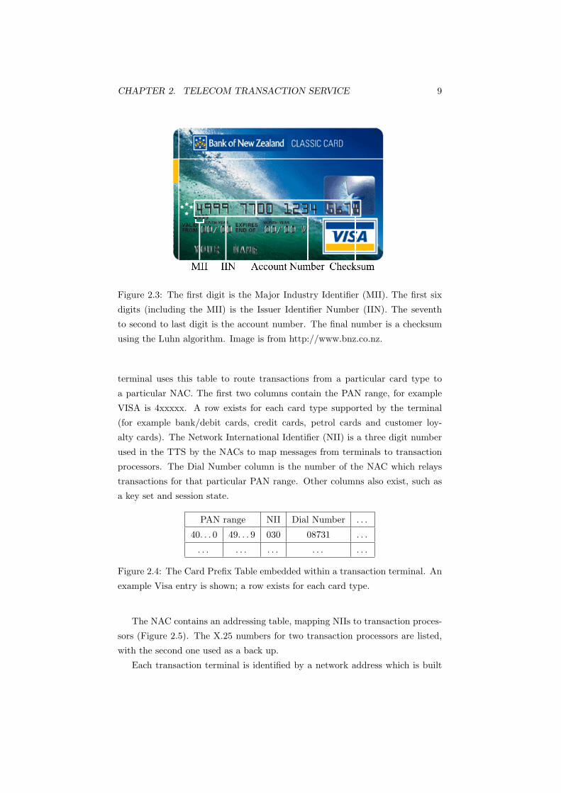
ISO 78121 is a standard for magnetic stripe cards (such as door entry, ATM and
credit cards). ISO 7812 defines a Primary Account Number (PAN), which is
typically 13, 16 or 19 digits in length. The PAN is normally printed or embossed
onto the card itself (Figure 2.3). The first digit is referred to as the Major
Industry Identifier (MII). This identifies which industry the card is used in, for
example 4 and 5 are banking/financial categories. The first six digits (including
the MII) are referred to as the Issuer Identifier Number (IIN). This identifies the
card issuer, for example 4xxxxx is Visa, 51xxxx-55xxxx is MasterCard. IINs are
assigned by the American Bankers Association and are managed like IPs and
radio frequencies.2 The IIN was also known as the Bank Identification Number
(BIN). The next sequence of numbers is the account number. This can be up
to 12 digits in length. The final digit is a checksum using the Luhn algorithm.
Inside each transaction terminal is a card prefix table (Figure 2.4). The
1http://www.merriampark.com/anatomycc.htm2http://www.ansi.org/other services/registration programs/iin registration.aspx
CHAPTER 2. TELECOM TRANSACTION SERVICE 9
Figure 2.3: The first digit is the Major Industry Identifier (MII). The first six
digits (including the MII) is the Issuer Identifier Number (IIN). The seventh
to second to last digit is the account number. The final number is a checksum
using the Luhn algorithm. Image is from http://www.bnz.co.nz.
terminal uses this table to route transactions from a particular card type to
a particular NAC. The first two columns contain the PAN range, for example
VISA is 4xxxxx. A row exists for each card type supported by the terminal
(for example bank/debit cards, credit cards, petrol cards and customer loy-
alty cards). The Network International Identifier (NII) is a three digit number
used in the TTS by the NACs to map messages from terminals to transaction
processors. The Dial Number column is the number of the NAC which relays
transactions for that particular PAN range. Other columns also exist, such as
a key set and session state.
PAN range NII Dial Number . . .
40. . . 0 49. . . 9 030 08731 . . .
. . . . . . . . . . . . . . .
Figure 2.4: The Card Prefix Table embedded within a transaction terminal. An
example Visa entry is shown; a row exists for each card type.
The NAC contains an addressing table, mapping NIIs to transaction proces-
sors (Figure 2.5). The X.25 numbers for two transaction processors are listed,
with the second one used as a back up.
Each transaction terminal is identified by a network address which is built

CHAPTER 2. TELECOM TRANSACTION SERVICE 10
NII Transaction Processor 1 Transaction Processor 2
030 4709000 9312000
Figure 2.5: The NAC addressing table. This determines which transaction
processor should handle the transaction, based on the NII.
up as it progresses through the network. This address is only unique within
a NAC, not between NACs. This address also does not identify which NAC
the terminal is connected to. Therefore, transaction processors must use the
existing X.25 circuit (created by the NAC to send the initial request) to send
replies, or provide its own mapping to establish which NAC the terminal is
connected to.
When a card is swiped, the transaction terminal connects to the NAC using
the Dial number field in the Card Prefix Table, according to the card type.
The terminal uses the NII as the network destination, that is, the transaction
processor.
When the NAC receives this, it establishes a virtual circuit to the transac-
tion processor specified in the NII if one does not already exist. A NAC has
at most one circuit for each transaction processor. If a virtual circuit cannot
be established with the primary transaction processor, the NAC attempts to
establish one with the back up secondary address.
After the transaction has been sent, the transaction processor replies (for
example an ‘Accepted’ or ‘Declined’ response) using the same circuit. After the
transaction is completed, the NAC holds the idle circuit up for three minutes
before clearing the call. If additional data is transferred (for example further
transactions) the timer is reset.
2.5 Previous Approaches
Most available approaches focus on using a legacy gateway to convert protocols
[11]. The remote device connects to the gateway (using the legacy protocol) as if
it were a telephone exchange. The gateway extracts the application layer data,
and sends this to the transaction processor (or any other destination) over the
replacement protocol (for example TCP/IP). These legacy gateways, or EFT to
IP Converters, can also log transactions to provide statistical information for
the merchant.
Several vendors offer this as a solution, such as Hypercom and Braintree
Communications. Solutions such as these are a stopgap measure at best, as they
CHAPTER 2. TELECOM TRANSACTION SERVICE 11
essentially enable older equipment to be connected to the new network. These
methods will be valuable during a migration phase, when an IP based short
transaction network must support both new IP and legacy protocol transaction
terminals.
Attempts intended for native IP transaction terminals have also been made.
Unfortunately, many of these never progressed past the experimental phase of
development, or are proprietary. These are described in detail in Section 3.
Supervisory Control and Data Acquisition (SCADA) systems provide a method
to obtain and process data from remote locations. Such systems are typically
the foundation of utility control systems [52, 54]. Utility control systems have
many applications such as power plants, water/waste utilities, refineries, oil/gas
transmission, distribution and production, communication networks and indus-
trial control.
A SCADA system provides monitoring and control of remote devices and
processes in real time. Measurements may be pressure, flow rate or tempera-
ture and can alert operators to component faults. SCADA systems use a polling
scheme similar to the NAC method; the monitoring station periodically polls
the remote terminal units (RTU) for monitoring of system statistics. Another
polling technique is a round robin method. In this method the monitoring
station sequentially polls each RTU. When one RTU has been polled, the mon-
itoring station polls the next RTU. This results in continuous utilisation of the
communication line. The sampling rate then depends on the number of RTUs
on the line.
While the SCADA architecture has many of the same requirements as a
transaction network, for example short delay notification and messaging, the
model is slightly different. SCADA monitoring stations initiate connections to
the remote devices, while in a transaction network such as EFTPOS, it is the
remote devices (transaction terminals) which initiate connections to the central
station, the NACs in this case
IBM’s Message Queuing Telemetry Transport (MQTT) [19, 85] is another
architecture for real time messaging. It has the same goals of remote data acqui-
sition as SCADA, however the model is a subscribe/publish model, as opposed
to SCADA’s poll/response model. Subscribers (for instance a monitoring sta-
tion) connect to a repository and subscribe to a topic, for instance flow control
in a pump station. The remote device, for example the pump station, publishes
messages to the message repository. The repository then distributes the mes-
sages to all subscribed clients. The message repository can also store messages
for offline clients and deliver them when they come online again. MQTT is

CHAPTER 2. TELECOM TRANSACTION SERVICE 12
based on TCP/IP like third generation SCADA systems [83] and features three
Quality of Service (QoS) levels: best effort, at least once and exactly once.
Like the SCADA architecture, MQTT is not aligned with the messaging
model of EFTPOS. It would not make sense to publish the data from a single
transaction terminal to several subscribers as only a single transaction processor
is needed to process a transaction.
2.6 Requirements
Based on the description of the current EFTPOS system, the requirements for
the new system can be formulated. The solution has the following requirements:
Low Delay: The current system has a mean round trip latency between the
terminal and host of 2.4 seconds (1.2 seconds each way). This depends on
the network used. Total transaction time is approximately 15 seconds.
Transaction Aggregation: Aggregating a large number of messages onto one
connection reduces costs and network requirements. The reduced connec-
tion load on transaction processors also improves performance and relia-
bility. This is currently provided by NACs and terminal controllers.
Reliable Transport: A guaranteed ‘at most once’ delivery is required, not
‘best effort’. The current system uses SDLC and X.25 to provide link
level acknowledgement, flow control and error recovery.
Reliable Network with High Availability: The network must have fault
tolerance and a degree of ‘network intelligence’; terminals will know which
servers/connections are down and use alternatives. Terminals also know
whether the service is available or not. This requirement includes redun-
dancy, alternate routing and load sharing.
In the current system, terminals using dial up access can determine whether
the link is alive by the presence of a dial tone. NACs also poll terminals,
notifying them of the NAC status. NACs have a back up transaction pro-
cessor to establish circuits with, if it cannot establish one with the primary
transaction processor. The NMS also periodically polls NACs to learn of
their status.
Network Management: With network intelligence, the status of all compo-
nents in the network should be known at any or all times. This includes
reporting, controlling and measuring transactions in the network. Faults

CHAPTER 2. TELECOM TRANSACTION SERVICE 13
must be easily diagnosed and located quickly. This is currently provided
by the NMS.
Scalable 1: The system must support a large number of terminals connected
to a relatively small number of central processors.
Scalable 2: The system must support high connection rates.
Scalable 3: The system should be designed to support peak, not average load.
When the transaction processor is overloaded during congestion, the trans-
action rate should be throttled.
Secure: Perfect forward secrecy is required with one time session keys. The
system must be secure from external risks as well as internal risks (for
example rogue or hijacked clients within the network). This is provided
in the current system through the use of X.25’s CUGs, the proxied access
model via the NACs and the specialised equipment required to access
the network. The connections to terminals are rate limited, making DoS
attacks from a single client impossible.
Efficient 1: The solution must be simple enough to implement easily.
Efficient 2: The solution must operate under limited bandwidth environments.
In the current system, terminals use a 1200 bps link. However, with
modern networks, speeds of at least several kilobits per second are possible.
Modern broadband links are at least several megabits per second.
Efficient 3: The solution must be able to operate on embedded devices with
low processing power and perform encryption in reasonable time. The
current system only performs encryption at the application level; AS2805
only encrypts the PIN using the Triple DES (3DES) cipher.
Use Active, Industry Supported, Open Standards and Protocols: Open
systems and protocols have the benefit of being exposed to peer review,
public scrutiny and criticism that in turn may expose performance and
security issues. While exposing these makes the protocol potentially more
vulnerable to attack, more important is that the vulnerabilities drive de-
velopment in order to reduce or remove the risk, making the vulnerability
a temporary one. This is more desirable than the ‘security by obscu-
rity’ model, where the security of a system relies on knowledge being kept
secret. Knowledge which must be kept secret is a potential point of vul-
nerability. Open standards also improve connectivity; when proprietary
protocols are used, only devices from one particular vendor can be used.
Chapter 3
Candidate Protocols
This section introduces several transport protocols (not necessarily layer 4 in
the OSI model) which could support the requirements defined in Section 2.6.
3.1 Transmission Control Protocol (TCP) - RFC
793
Transmission Control Protocol (TCP) is one of the core transport protocols in
the Internet Protocol suite, the other being User Datagram Protocol (UDP). It
is defined in RFC 793 [97]. As it is widely used and published, it will not be
detailed here.
In terms of its suitability for this project, RFC 955 [28] asserts that TCP
is at one end of possible transport service attributes and UDP is at the other
extreme. TCP provides a reliable flow controlled transfer. Packets can also be
fragmented at the sender end and reassembled at the destination. The packet
stream offered by TCP means the application must provide its own message
framing to distinguish separate messages. TCP also features congestion control
features. However, TCP lacks fault tolerance functionality present in newer
transport protocols, such as multihoming and link failure in SCTP, described
in Section 3.4. Fault tolerance improves reliability as it notifies the client that
the network peer is not responding.
TCP features an explicit connection establishment and termination phase.
In terms of transactions where the transaction consists of a single packet sent and
received in response, the establishment and termination phases would constitute
a larger number of packets sent and received than the actual transaction itself.
However, this may be a minor issue; when the transaction establishment does
14

CHAPTER 3. CANDIDATE PROTOCOLS 15
make up a large proportion of the total transaction time, the total transaction
time is likely to be no more than several seconds. This duration is acceptable
for short duration transaction systems such as EFTPOS. This allows a TCP
based short transaction system to operate adequately even in an environment
with a large RTT.
By itself, TCP cannot be considered a suitable component for this project.
While it provides a reliable, flow controlled connection, it is not message oriented
and also lacks fault tolerance functionality.
3.2 User Datagram Protocol (UDP) - RFC 768
User Datagram Protocol (UDP) is the other core transport protocol in the
Internet Protocol suite. It is defined in RFC 768 [96]. As its operation is widely
used and published, it will not be detailed here.
Unlike TCP, UDP is a message based protocol. This relieves the application
from having to provide its own message framing. UDP is unreliable, which
means packets may be duplicated, lost or unordered. Applications will then
need to provide for timeouts and retransmissions.
As UDP is unreliable and does not establish a connection or virtual circuit
before sending data, it has no congestion control features. As a result, any
congestion in the network may be worsened by UDP. The solution would be
to implement congestion control at the application layer, however as there are
transport protocols which have congestion and flow control built in, this would
unnecessarily complicate the application.
While UDP is a message based protocol and has no connection phase, it lacks
reliability and has no flow or congestion control mechanisms. Consequently,
UDP by itself cannot be considered a suitable transport protocol for this project.
Attempts have been made to build reliability and flow control on top of UDP
and one example, QTP, is described in Section 3.5.
3.3 Transaction TCP (T/TCP) - RFC 1644
Transaction TCP (T/TCP) is an experimental backwards compatible extension
to TCP, defined in RFC 1644 [30]. T/TCP is designed to provide reliable and
efficient client-server transaction oriented traffic. The extensions aim to make
available a transport protocol as reliable as TCP and as fast as UDP. T/TCP
improves upon TCP in two ways: by bypassing the 3-way handshake (3WHS)
and shortening the delay in the TIME-WAIT state. Bypassing the 3WHS means

CHAPTER 3. CANDIDATE PROTOCOLS 16
a T/TCP connection can approach a UDP connection in terms of speed, while
maintaining the reliability of a TCP connection [109]. Rather than performing
the 3WHS before transferring data, T/TCP carries the user data in the initial
connection establishment packet, reducing the number of packets required to
perform a transaction to 2, therefore improving transaction times. Shortening
the TIME-WAIT delay enables sockets to be cycled and reused more often,
increasing the rate at which a client can send transaction requests.
3.3.1 Bypassing the 3-way handshake
The 3WHS is bypassed through use of a mechanism called TCP Accelerated
Open (TAO) (Figure 3.1). Standard TCP necessitates the use of the 3WHS to
prevent the receiver from confusion by the receipt of old duplicate connection
initiations. The receiver of the initial SYN responds with an ACK, verifying
with the sender that the connection request is not an old one that arrived out of
order. T/TCP achieves this without using the 3WHS by using a monotonically
increasing 32-bit incarnation number called a connection count (CC). This is
carried in the T/TCP header as a new TCP option anytime a client wishes to
initiate a connection with a server. A server supporting T/TCP keeps a cache
of the last valid CC for each client. When a client first connects to a server
(Figure 3.1(a)), the server has no CC state for that client, so a normal 3WHS
is performed. On this initial connection, the server initialises the CC for that
particular client on successful completion of the 3WHS. Subsequent connections
from that client use an incremented CC value. When the server receives a con-
nection request, the CC value in the connection request is compared with the
corresponding client’s cached CC value on the server. If the incoming value is
larger than the cached value (Figure 3.1(b)), the SYN is considered new and
the connection is considered established. The user data is passed to the appli-
cation layer immediately and the cached CC value is updated. If the incoming
CC value is not larger than the cached value, a normal 3WHS is performed to
validate the connection request, as the server has no way of knowing whether
the SYN is an old duplicate, or was delivered out of order. This comparison
of CC values is known as the TAO test. If the TAO test succeeds, an optimi-
sation is realised in the form of reducing the connection establishment by one
RTT. The user data is passed to the application layer as soon as it is received,
otherwise the server queues the user data and falls back to the usual 3WHS of
TCP to validate the SYN. Falling back to TCP also provides for reliability and
backwards compatibility.
T/TCP effectively reduces the number of segments required to perform a

CHAPTER 3. CANDIDATE PROTOCOLS 17
(a) The first connection attempt requires the use of the 3WHS to validate the SYN.
(b) Subsequent connection bypasses the 3WHS through use of the TAO test.
Figure 3.1: The TCP Accelerated Open (TAO) bypasses the 3WHS to minimise
the number of segments exchanged to perform a transaction (adapted from [30]
and [111]).
request-response transaction to three segments and because the data is carried
in the first two, the applications see the user data at the same speed as if UDP
were used. Notice in Figure 3.1(b), the initial segment contains the SYN, data
(data1) and FIN. After the data is passed to the application layer, the FIN is
processed and the server responds with its SYN, ACK and FIN flags as well as
any response data (data2). The client processes the received SYN and ACK,

CHAPTER 3. CANDIDATE PROTOCOLS 18
and passes the server’s reply to the application layer. The client also uses the
CC.ECHO option to validate the server’s SYN ACK segment. When the FIN
is processed, the client responds with a final ACK and moves into the TIME-
WAIT state. When the server receives the ACK of its FIN, the connection is
closed. This example shows how a connection is established and closed with a
minimal exchange of segments.
It is possible for the CC values to wrap around, for example: connections
which last longer than the Maximum Segment Lifetime (MSL), as the CC values
are global to all connections; the client crashing, rebooting and reinitialising the
CC generator back to 1; or simply reaching the end value. Since all subsequent
connections will have lower CC values than the cached value on the server, there
will be a performance degradation, as the TAO test will fail. This causes the
hosts to perform the 3WHS each time they initiate a new connection. Clients
avoid this by specifying the CC.NEW option, which updates the server’s CC
cache to the new value.
3.3.2 Truncation of the TIME WAIT state
The TIME-WAIT state exists in TCP to ensure the remote host has received
the acknowledgement (ACK) of its connection termination request (FIN). Upon
receiving a connection termination request, a host enters the TIME-WAIT state
for twice the MSL, usually between 60 and 240 seconds (Figure 3.2). In this
state, the port pair (C:P and S:P) cannot be reused; a host can only receive
and acknowledge the retransmission of a remote FIN. This keeps old packets
from the closed connection still in the network from interfering with another
connection created using the same socket pair, should they be reused. For
example if a server retransmitted a FIN (as the client’s final ACK was lost), the
TIME-WAIT state would ensure that the client responded by retransmitting
the lost ACK, rather than an RST which would happen if the client was not in
the TIME-WAIT state. The wait time of 2MSL also ensures that any remaining
packets from the previously closed connection expire.
Shortening the TIME-WAIT state can increase transaction rates and is pos-
sible in T/TCP due to the introduction of the CC value. The CC value protects
against old duplicates, as the value increases with each new connection. In
T/TCP, the time spent in the TIME-WAIT state is a multiple of the retrans-
mission timeout (RTO, of 1.5 seconds [111]) instead of the MSL; it is reduced
to 12 seconds, eight times the RTO (Figure 3.3). The RTO multiplied by eight
ensures that the sender has an opportunity to retransmit any unacknowledged
segments. It is clear, when comparing TCP’s TIME-WAIT state (Figure 3.2)

CHAPTER 3. CANDIDATE PROTOCOLS 19
Figure 3.2: TIME WAIT state in TCP (from [111]). A client-server port pair
(C:P and S:P) cannot be reused for 2MSL (typically 240 seconds) after a con-
nection has been closed.
Figure 3.3: TIME WAIT state in T/TCP (from [111]) when different ports are
used for each transaction. The client-server port pair (C:P and S:P) can be used
sooner than in TCP.
with T/TCP’s (Figure 3.3) that shortening the TIME-WAIT state makes ports
available for use sooner and more often.
A further optimisation is possible if the client and server reused the same
ports for a subsequent transaction (Figure 3.4). The TIME-WAIT state ends as
soon as another transaction is initiated via use of the CC values. For example
if a client had received a FIN, an ACK would be sent in response. If this ACK
was lost but the client initiated a new transaction before the retransmitted
FIN arrived, the exchange would continue as normal. This is possible because
the new SYN would have a higher CC value and the TAO test would succeed.
This implicitly acknowledges the server’s unacknowledged FIN. The server then
closes the old connection and starts a new one. The data contained in the
newly received SYN is then passed to the application layer (as the TAO test
succeeded).
A constraint on the truncation of the TIME-WAIT state is that the duration
of the connection must be less than the MSL (which is typical of a simple request-

CHAPTER 3. CANDIDATE PROTOCOLS 20
Figure 3.4: TIME WAIT state in T/TCP (from [111]) when the same ports are
reused for each transaction. The client-server port pair (C:P and S:P) can be
reused when a new connection is initiated.
Figure 3.5: Truncation is possible here, as the connection duration is less than
the MSL of 120 (from [111]).
response transaction in any case). The T/TCP RFC states that “The essential
requirement for correctness of T/TCP is this: CC values must advance at a rate
slower than 231 counts per 2MSL where MSL denotes the maximum segment
lifetime in the Internet”. This requirement ensures that a particular CC value
for a particular connection (that is, a port pair) is not reused for at least 2MSL.
Thus if the duration of a connection exceeds the MSL (120 seconds in TCP’s
specification, RFC 793, [97]), the TIME-WAIT state interval must revert to
TCP’s delay of 2MSL (240 seconds) to protect from old duplicates. Figures 3.5
and 3.6 (from [111]) illustrate why. In Figure 3.5, a connection starts at time 0
with a CC of 1, and lasts for 100 seconds. The TIME-WAIT state starts at time
100 and lasts until time 112 or until the client initiates another transaction using
the same ports, whichever comes first. As the MSL is 120, all segments from this
CHAPTER 3. CANDIDATE PROTOCOLS 21
connection will have expired by time 220. As the CC values repeat only every
240 seconds (2MSL), in this instance it is safe to truncate the TIME-WAIT
state (as the connection’s duration was less than MSL).
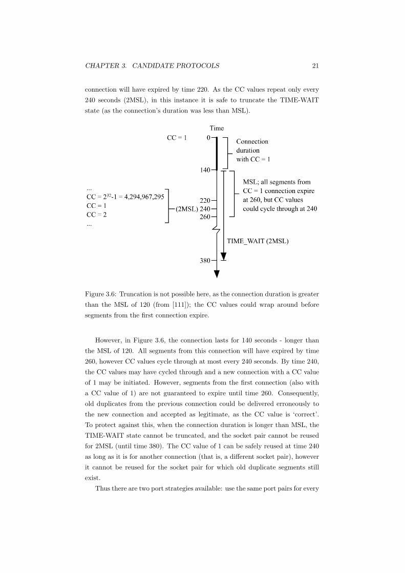
Figure 3.6: Truncation is not possible here, as the connection duration is greater
than the MSL of 120 (from [111]); the CC values could wrap around before
segments from the first connection expire.
However, in Figure 3.6, the connection lasts for 140 seconds - longer than
the MSL of 120. All segments from this connection will have expired by time
260, however CC values cycle through at most every 240 seconds. By time 240,
the CC values may have cycled through and a new connection with a CC value
of 1 may be initiated. However, segments from the first connection (also with
a CC value of 1) are not guaranteed to expire until time 260. Consequently,
old duplicates from the previous connection could be delivered erroneously to
the new connection and accepted as legitimate, as the CC value is ‘correct’.
To protect against this, when the connection duration is longer than MSL, the
TIME-WAIT state cannot be truncated, and the socket pair cannot be reused
for 2MSL (until time 380). The CC value of 1 can be safely reused at time 240
as long as it is for another connection (that is, a different socket pair), however
it cannot be reused for the socket pair for which old duplicate segments still
exist.
Thus there are two port strategies available: use the same port pairs for every
CHAPTER 3. CANDIDATE PROTOCOLS 22
transaction to save TCP resources (Figure 3.4), in which case if the duration
of the connection is greater than MSL, the TIME-WAIT state delay must be
at least 2MSL, otherwise the TIME-WAIT state can end upon initiation of a
transaction; or use different ports for each transaction (Figure 3.3), which means
applications do not need to be programmed to use the same port number. In any
case, as long as the connection duration is less than the MSL, the TIME-WAIT
state is always truncated from 2MSL to 8RTO.
As most transaction oriented connections usually exist for much shorter than
120 seconds, T/TCP offers an optimisation, as resources are available more often
and are cycled through faster, making higher transaction rates possible.
3.3.3 Security Vulnerabilities
While T/TCP has attractive features aimed specifically at improving request-
response transactions, there are weaknesses which make it more vulnerable than
TCP. Spoofing a connection is almost certain to be successful and significantly
easier under T/TCP than TCP [46]. When the TAO test succeeds, the server
considers the connection to be established and the data is passed to the appli-
cation layer immediately. Thus, all an attacker needs to do is succeed the TAO
test. There are two simple methods to succeed the TAO test, and therefore
spoofing a T/TCP connection; the attacker can either perform packet sniffing
to discover the current CC value, or simply use a large value for the CC.
If the attacker is on the same network as the host to be spoofed, the current
CC value of the connection between the host and the server can be discovered via
packet sniffing. Once this is discovered, all the attacker needs to do is increment
the discovered CC value and initiate a connection to the server, using the source
address of the spoofed host. The monotonically increasing property of the CC
value ensures the TAO test will succeed, and the data will be passed to the
application layer on the server immediately.
The other method is to simply use a large value for the CC value. If the
attacker is unable to sniff out the current CC value, using a large CC value
has a high chance of succeeding the TAO test, as all observed implementations
initialise the CC value to 1 [105]. The CC value is a 32-bit unsigned number,
with a maximum value of 232 − 1. The chance that a particular host has used
even half of these values is unlikely. Therefore the higher the CC value used,
the greater the probability of success.
These two methods not only have a high or certain chance of success, they
also ensure that subsequent connection requests from the legitimate host fail
the TAO test, as the server updates the CC cache with each successful connec-
CHAPTER 3. CANDIDATE PROTOCOLS 23
tion. The payload of such spoofed connections can be the same as those used
under TCP, such as the command ‘echo ‘‘+ +’’ >> /.rhosts’, used in Unix
to extend trust to any user from any host. Sending a spoofed packet with an
acceptable CC value to succeed the TAO test, with the Unix command as the
payload, is all that is needed to compromise the server. Unlike TCP, sequence
numbers do not need to be predicted to establish the connection, making the
attack almost effortless, as only one packet is needed. The 3WHS provides a
limited degree of validation of the sender’s address, and removing this greatly
eases the spoofing of complete connections. Use of the TAO mechanism also
negates the use of randomised initial sequence numbers (ISN) for each connec-
tion as well as incrementing the sequence numbers every half second - the best
techniques for preventing spoofed TCP connections.
Another weakness of T/TCP is its vulnerability to SYN flooding, which
leaves the server unable to accept new connections, as all the resources are
devoted to multiple half-open connections due to spoofed connection requests.
While TCP is also vulnerable, under T/TCP, SYN flooding is more harmful and
harder to defend against. To reduce transaction overheads, T/TCP carries data
(a request from the client) in the initial SYN. If the TAO test fails, the server
queues the data until the fallback 3WHS succeeds. As a consequence, a SYN
flood can do more damage under T/TCP, as an attacker can spoof SYNs such
that each connection request fails the TAO test. With data queued from many
connection requests (due to each one failing the TAO test) memory buffers can
be exhausted faster than if TCP were used. The reduced TIME-WAIT state
also enables attackers to send requests faster when attacking from the same
address and port, which makes T/TCP very prone to DoS attacks.
Strictly speaking, TCP is also vulnerable to queuing the data of pending
connections. TCP, however, can be implemented such that data sent with the
initial SYN can be discarded. This would require the client to retransmit the
data, after the connection is established with the 3WHS. However, if this were
applied to T/TCP (which is completely feasible) it would not be aligned with
the goal of providing fast transaction processing as the client would need to
retransmit the data, effectively reducing the speed to that of TCP.
A method to protect against SYN flooding is the use of SYN cookies [118].
A SYN-cookie is a cryptographically generated ISN, based on the source IP
address, port and other data. When a SYN is received to request a connection,
the server responds with a SYN-ACK, with the SYN-cookie as the ISN. When an
ACK is received in response, the sequence number in the ACK is validated, and
only then does the server allocate state, a buffer and open the connection. If the

CHAPTER 3. CANDIDATE PROTOCOLS 24
sequence number is invalid, the packet is dropped. Use of the SYN-cookie makes
a stateless handshake possible, as resources are allocated only on receipt of the
final ACK from the client, rather than on sending the SYN-ACK. As a result,
the risk from SYN flooding is greatly reduced, as half-open pending connections
cannot exist. Unfortunately this technique cannot be used with T/TCP. The
TAO makes use of the CC value, which is carried in the TCP options part of
the header. As the server does not hold any state for a connection until the
final ACK form the client is received, any TCP options in the initial SYN (and
therefore the CC value) would be lost, meaning the CC value cannot be cached.
Figure 3.7: T/TCP can deliver duplicate data due to use of the TAO mechanism
(from [105]).
Finally, T/TCP is not completely compliant with TCP in some instances.
Use of the TAO mechanism can cause duplicate data to be delivered ‘legiti-
mately’ to the application layer. This is illustrated in Figure 3.7. In this ex-
ample (from [105]), the client sends the first part of a transaction (the request)
to the server. The two hosts have established their CC values, so the TAO test
succeeds. The server passes the data in the request to the application layer,
however it crashes before it can send its ACK (the response part of the trans-
action). The client times out as it has not received an ACK, so retransmits the
request. After the server has rebooted, it receives the request again, however
this time the TAO test fails, as the server’s CC cache is reinitialised and thus
invalid. Consequently, the server queues the data carried in the request, and
performs the 3WHS. When this is completed, the queued data is passed to the
application layer for the second time as the server maintains no state after a
reboot, and therefore cannot identify duplicate requests. A required attribute

CHAPTER 3. CANDIDATE PROTOCOLS 25
of a transaction system (as described in Section 2.6) is ‘exactly-once’ semantics,
and the functional specification of T/TCP does not conform to this.
In addition, page 73 in RFC 793 states “Do not process the FIN if the state
is CLOSED, LISTEN or SYN-SENT since the SEG.SEQ cannot be validated;
drop the segment and return”. This means when a standard TCP server receives
data with both the SYN and FIN flags set (that is, from a T/TCP client),
the segment will be dropped; sending a FIN with a SYN flag violates TCP’s
processing rules [58]. Most servers drop the FIN and processing will require a
3WHS to continue, however, T/TCP will be unable to communicate with TCP
servers that conform strictly to the TCP specification. In this situation, T/TCP
is not compatible with TCP.
3.3.4 Implementations and Development
RFC 1644 was published in 1994, and remains in experimental state. There have
been several implementations of T/TCP in several operating system kernels:
Linux, SunOS and FreeBSD.1 Patches exist for up to Linux kernel version 2.4
(which was released in January 2001), however the development2 never went
past the beta stage. Backward compatibility problems also exist in Solaris
implementations, when a T/TCP enabled client connects to a standard TCP
server. In Solaris 2.4 (SunOS 5.4), a standard TCP server’s stack dropped the
data in the initial SYN and did not acknowledge it [111]. This caused the
T/TCP client to timeout and retransmit the data. A patch was issued in 19983
for the FreeBSD kernel, addressing the spoofed connection vulnerability (when
the .rhosts file is used as the only method of authentication).
Enhanced Transaction TCP [27] proposes solutions for the security and back-
ward compatibility problems in the current experimental specification. To re-
duce the risk from spoofed connections, CC value is made a socket variable,
instead of a global variable as defined in RFC 1644. This has two advantages;
the server can now handle up to 232 − 1/2MSL transactions per second per
client, instead of 232 − 1/2MSL transactions per second globally. Secondly, the
CC values can now have predictable increments as the CC value spaces are now
specific to each client. Consequently the TAO test can be modified so CC values
must be exactly one larger than the cached value. Another measure suggested
was to randomise the CC value instead of initialising it to 1. This would reduce1http://www.kohala.com/start/T/TCP.html. This site also lists several T/TCP enabled
internet hosts.2http://sourceforge.net/projects/ttcplinux (accessed February 2007).3http://ciac.org/ciac/bulletins/i-051.shtml

CHAPTER 3. CANDIDATE PROTOCOLS 26
the ease of spoofing a connection, which only needed to use a high enough CC
value to succeed.
To reduce the risk from SYN-flooding, use of a SYN-cache was suggested in
[79]. Normally when a server receives a SYN, the whole Transmission Control
Block (TCB)4 for that connection is allocated. Thus when a SYN flood is
taking place, the server’s resources are tied up in the TCB’s of the attacker’s
pending connections. SYN caching, on the other hand, allocates minimal state
when the server receives a SYN. This state records TCP options which are not
retransmitted in the ACK from the client, such as the CC value. The full TCB
is allocated only when the connection is established. A limit is placed on the
amount of cached state to place a bound on the amount of memory the SYN
cache uses. When this limit is reached, the oldest entry is dropped. Use of
the SYN cache therefore limits the damage potential from a SYN flood. In
addition, following the failure of the TAO test, the server should not queue the
data, as this can aid an attacker when performing a DoS attack by consuming
more memory.
As for duplicate deliveries, two-phase commits and transaction logging can
eliminate this problem, that is, make the application layer responsible [109].
3.3.5 Summary
T/TCP was designed for simple request-response transactions. It aimed to pro-
vide a protocol as fast as UDP, but with the reliability of TCP. It reduced the
overhead required to establish a connection by including the data in the initial
connection establishment segments and by bypassing the 3WHS through use of
the CC value. This enabled the application layer to receive the data as fast as
if UDP were used. The other main improvement upon TCP was the truncation
of the TIME-WAIT state. This reduced the time ports were unavailable for
use after closing a connection, which enabled higher transaction rates. Unfortu-
nately the use of the CC value greatly eased the spoofing of connections, as all
attackers needed to do to ensure success was to use a large enough CC value - a
CC value larger than the cached value on the server was all that was needed to
accept the data and pass it to the application layer. With TCP, the attacker had
to at least guess the sequence numbers and this could be made more difficult
with randomised sequence numbers and half-second increments to the numbers
- defence techniques that cannot be used to protect T/TCP. The other major
security flaw in T/TCP was its risk from SYN flooding; while TCP is also vul-
nerable, T/TCP would typically exhaust the server’s memory faster. The most
4An operating system uses these to maintain a transport protocol’s connection.

CHAPTER 3. CANDIDATE PROTOCOLS 27
effective protection against this, SYN cookies, again cannot be used to protect
T/TCP. In some instances, T/TCP is not compatible with TCP, leading to du-
plicate message delivery to the application layer, or no communication at all
with a strictly implemented TCP host.
There have been limited deployments and implementations of T/TCP and a
distinct lack of active development in the protocol. Enhanced T/TCP proposes
solutions to T/TCP’s shortcomings, however it has not had any deployment or
implementation in any major Unix/Linux distribution. The requirements that
T/TCP had set out fulfil are highly aligned with those in Section 2.6. In fact,
parts of those requirements in Section 2.6 are adapted from RFC 1644, and
T/TCP in concept, meets those requirements. However, given the serious secu-
rity issues, its lack of development, implementation, deployment and maturity,
it cannot be considered a viable transport protocol suitable for the requirements
described in Section 2.6.
3.4 Stream Control Transmission Protocol (SCTP)
- RFC 2960
Stream Control Transmission Protocol (SCTP) is a transport layer protocol
originally designed to transport SS7 telephony messages over an IP network
[53]. SCTP was developed by the IETF Signalling Transport (SIGTRANS)
working group and is currently a proposed standard as RFC 2960 [114].
The information carried in SS7 PSTN signalling messages are for call man-
agement, such as call set up and teardown, billing and routing and value added
services, for instance call waiting and caller identification [32]. Such messages
require reliable and timely delivery as errors or delays can result in disruption
of the service (for example failure to establish a call or billing errors). With
the growth of VoIP, a transport protocol was needed to transport SS7 signalling
messages over IP. Until late 2000, TCP and UDP were the only prospective
transport layer protocols in the TCP/IP suite. UDP does not provide reliable,
in-order transport, or any form of congestion control. Without flow control, the
send rate remains constant, worsening the effects of any network congestion.
Congestion in turn makes UDP even more unreliable as data will be discarded.
Because of these shortcomings, UDP was not considered. TCP, with respect to
carrying PSTN signalling, had the following limitations (from [114]).
• TCP provides strict order-of-transmission delivery. Applications that do
not require sequential delivery may suffer from unnecessary delays due to
CHAPTER 3. CANDIDATE PROTOCOLS 28
Head-of-Line (HoL) Blocking
• As TCP is stream-oriented (or byte-oriented), it delivers a stream of bytes.
Applications that process individual messages (such as a PSTN signalling
message) need to add their own application level message framing within
the TCP byte stream. Applications must also explicitly use TCP’s PUSH
facility to ensure complete messages are sent with minimum delay (as
opposed to the standard behaviour of blocking data together and sending
when convenient).
• TCP does not support multihoming; a single destination IP address is
bound to a particular TCP connection. If this connection fails, it must be
re-established. This does not meet the signalling transport’s requirement
of high availability and network resilience.
• TCP is relatively vulnerable to DoS attacks, such as SYN-flooding
As a result of TCP’s limitations, SCTP was proposed to carry PSTN sig-
nalling across an IP network. Even though SCTP’s design was motivated by
this need, it is considered a general-purpose protocol; like TCP, SCTP provides
a reliable, full duplex connection with congestion avoidance mechanisms.
SCTP’s congestion control functions are based on the rate-adaptive, window-
based scheme of TCP. This includes slow start, congestion avoidance and fast re-
transmit [113]. As these are derived from those of TCP, SCTP is ‘TCP friendly’;
SCTP applications can co-exist and share network resources with TCP appli-
cations without constrained or excessive use of the network. However, SCTP
improves upon TCP’s congestion window (cwnd). A congestion window reduces
the sending rate during network congestion by limiting the number of bytes
that can be inserted into a network. When no congestion is detected and all
the data in a window is acknowledged by the receiver, the slow start and con-
gestion avoidance algorithms (defined in RFC 2581, [21]) double the value of
cwnd. This is because the sender’s current sending rate does not appear to
be causing congestion. These algorithms assume that the cwnd is limiting the
sending rate. However, an application can send at a rate slower than what the
cwnd is limited to. This is common for signalling applications, as this ensures
the network remains functional in the event of a load spike [33]. Under this sit-
uation, TCP would increase cwnd exponentially. If the application has a sudden
burst of traffic, the large cwnd will allow all of it to be sent at once. This could
cause network congestion resulting in packet losses and timeouts. In SCTP,
cwnd can only be increased when the full cwnd is used, rather than doubling it
upon successful transmission as in TCP [53].

CHAPTER 3. CANDIDATE PROTOCOLS 29
SCTP’s flow control is also derived from TCP, more specifically TCP Selec-
tive Acknowledgements (SACK). TCP SACK is defined in RFC 2018 [81]. The
ACK in TCP is used to detect packet loss and is cumulative; it indicates the
last packet successfully received in sequence (therefore implicitly acknowledging
that all packets before the acknowledged packet were also received successfully).
SACK enables the receiver to acknowledge packets that have been received suc-
cessfully after packet loss. For example (from [33]) if a host receives packets 1,
2, 3, 5 and 7, it will respond with ACK(1), ACK(2), ACK(3), ACK(3), ACK(3).
When the sender receives ACK(3), it knows that packets up to 3 were success-
fully received in sequence. However, receiving ACK(3) multiple times indicate
that packet 4 was lost and needs to be retransmitted. The sender, however, is
unaware which packets after 3 were also lost or successfully received, so packets
after 4 are also retransmitted. With the SACK extension, the receiver would
have sent ACK(3)-SACK(5,7). The sender would then know to not only retrans-
mit packet 4, but also packet 6. This reduces the impact of multiple dropped
segments, as only the packets that were not sent successfully are retransmit-
ted thus saving bandwidth. Like congestion control, while SCTP’s flow control
is based on TCP’s, SCTP improves upon TCP’s mechanism - while SACK is
optional in TCP, it is a standard feature of SCTP.
Common Header
Data Chunk 1
. . .
Data Chunk n
Figure 3.8: The SCTP packet format. Multiple data chunks can be in a single
SCTP packet up to the MTU.
While SCTP inherits some features from TCP and can offer the same func-
tionality, it contains additional features to overcome TCP’s limitations. One
of these is conservation of message boundaries. Like UDP, SCTP is message
oriented. This simplifies applications that process individual messages, as the
transport protocol indicates the start and end of the message. One of the disad-
vantages of TCP is that the application must preserve the message boundaries
themselves. SCTP frames messages by carrying them in units called chunks. A
chunk consists of a header and the data. As illustrated in Figure 3.8, an SCTP
packet can contain multiple chunks. Large messages can also be fragmented
into multiple chunks and then reassembled at the receiving end. Fragmenting
user messages at the transport layer avoids fragmentation at the IP layer. IP

CHAPTER 3. CANDIDATE PROTOCOLS 30
layer fragmentation is undesirable as the protocol header (TCP, SCTP, UDP
etc), containing the destination and source port numbers, is contained only in
the first fragment [33]. As subsequent fragments do not contain this header
data, they may not be able to pass through NAT devices or firewalls. If the
path MTU changes (due to a change in the network path for example), SCTP in
some circumstances may be forced to perform IP fragmentation. If the receiver
is behind a NAT device, the data may never be received, causing the SCTP
association (equivalent to a connection in TCP) to timeout. This limitation is
described in [33].
Another important feature is multihoming. SCTP allows each endpoint of an
SCTP association to be accessible from more than one IP address. This provides
a level of redundancy (as required for SS7 signalling transport), as the failure
of the primary address (for example due to link failure or congestion) does not
disrupt the data transfer. When SCTP initialises as association, each endpoint
exchanges a list of addresses or host names from which they can receive data
from. The sending host selects one of the receiver’s addresses as the primary
address and uses this for all data transmission. Retransmitted data is sent to
an alternate address to improve the probability of successful transmission [87].
Sustained failure to send to the primary address causes the end point to send
all data to the alternate address, until the primary address becomes available
again. This change is potentially transparent to the sending application [71].
If this occurred in TCP, the connection would collapse, interrupting the data
transfer, as the connection would need to be re-established.
A requirement for multihoming to be effective is that the multiple addresses
need to be connected to different networks (for example different network ad-
dress prefixes or possibly ISPs) to ensure the traffic is transmitted over a differ-
ent network path in the event of primary address failure. The more diverse the
alternate network paths, the more fault tolerance multihoming affords; multi-
homing loses some effectiveness when the alternate paths meet at a single point
of failure, such as a single link or router.
SCTP detects the failure of a link via ACKs received from acknowledged data
and a heartbeat mechanism. A heartbeat request is sent periodically to each
of the remote endpoint’s idle alternate addresses to determine the state of the
link. The remote endpoint responds with a heartbeat acknowledgement, to con-
firm the link and endpoint’s availability. When the number of unacknowledged
retransmissions or heartbeat requests exceed a configured maximum parameter
(RFC 2960 recommends a value of 5 for the Path.Max.Retrans parameter), the
address is deemed to be unreachable, and an alternate address is selected to

CHAPTER 3. CANDIDATE PROTOCOLS 31
transmit data. Heartbeat requests are still sent to unreachable addresses, so
that addresses that do become reachable again can respond with a heartbeat
acknowledgement, and can be noted as active.
Figure 3.9: Head of Line blocking in TCP. Even though segments 3 to 5 are
transmitted successfully, they cannot be delivered to the application until seg-
ment 2 is successfully transmitted.
SCTP also adds multistreaming. An endpoint can only have one SCTP as-
sociation with a particular endpoint (an endpoint can have many concurrent
associations as long as they are with different endpoints [115]). Each associa-
tion, however, can contain multiple streams. Each stream is a unidirectional
flow of chunks; each chunk belongs to one stream. Streams are independent
of each other and in this way SCTP separates message reliability and message
ordering. This enables endpoints to transfer multiple ordered sequences of mes-
sages reliably, without the sequences interfering with each other. This avoids the
Head-of-Line blocking problem in TCP, which happens when separate streams
of data are multiplexed over a single TCP connection. For example in Fig-
ure 3.9, segments 1 to 5 belong to separate independent sessions. Segment 1,
3, 4 and 5 are delivered successfully to the host, however, segment 2 is lost.
Segment 1 is delivered to the application, but 3, 4 and 5 are queued as TCP
requires order-of-transmission delivery. Thus the delivery of 3,4 and 5 to the
application must wait until 2 has been successfully retransmitted and received,
even through they belong to different logical sessions. In SCTP, each indepen-
dent session can be transferred over a separate stream, ensuring that the loss in
one stream does not affect the other streams (Figure 3.10), thus avoiding HoL
blocking and associated delays.
It is important to note that within a stream, messages are normally still de-
livered in order-of-transmission, so HoL blocking still affects individual streams.
In Figure 3.10, if S1 and S2 were each a stream, stream S2 would operate nor-
mally, however stream S1 would be blocked until segment 2 of stream S1 was
successfully retransmitted and received by the remote endpoint.
SCTP also supports unordered reliable message delivery. This also avoids

CHAPTER 3. CANDIDATE PROTOCOLS 32
Figure 3.10: Use of multiple streams avoids Head of Line blocking. Even though
segment 2 of stream S1 has been lost, segments in stream S2 can still be delivered
to the application.
Figure 3.11: Use of unordered delivery also avoids Head of Line blocking.
Chunks that have been transmitted successfully can be delivered immediately
to the application, regardless of previously lost chunks.
HoL blocking, but this time within a stream. For example Figure 3.11 shows a
single stream. Chunks 1, 3, 4 and 5 have been specified for unordered delivery,
and can therefore be delivered immediately to the application. The delivery
mode is specified at the chunk level, so within a single stream, some chunks
can be specified for out of order delivery, and the rest delivered in order (the
default).
Previous work ([33, 55]) studying the effects of HoL blocking found that
the improvements in SCTP over TCP do not result in a large reduction in
transmission delay under normal conditions. Both studies found under normal
network conditions, the mean delays with SCTP and TCP cannot be statistically
differentiated. However, both also found as network conditions worsened (due
to congestion and high packet loss), SCTP and its avoidance of HoL blocking
provided a small (up to 18% in [55]) improvement in transmission delay.
While HoL blocking can be avoided in TCP by using multiple TCP connec-

CHAPTER 3. CANDIDATE PROTOCOLS 33
tions for each ‘stream’, there is increased overhead, as a TCB must be main-
tained for each connection (compared to one for the single multistreamed SCTP
association). If the server has insufficient memory, incoming TCP connection re-
quests may be dropped. This can also happen if the server runs out of ports. In
addition, an application utilising multiple TCP connections could get an unfair
share of the network bandwidth between the two hosts [115].
Establishing a separate connection for each ‘stream’ also increases the con-
nection set up delay, as each TCP connection must perform a 3WHS. In SCTP,
up to 65,535 independent streams can be established between two endpoints
with a single four-way handshake association initiation.
3.4.1 Association Initiation
As SCTP is connection oriented, an association must be established before data
can be exchanged. SCTP’s association establishment is similar to TCP’s SYN-
cookie mechanism; SCTP uses a four-way handshake to protect servers from
SYN flood DoS attacks. Figure 3.12 illustrates the association establishment
process [114]. The client initiates an association by sending an INIT chunk.
This chunk contains the required number of inbound and outbound streams (as
streams are unidirectional), an initiation tag, the initial Transmission Sequence
Number (TSN) and a list of all the IP address which the client can be accessed
from. The initiation tag is a randomised 32-bit integer and is used as the
verification tag during data transfer. This protects against blind ‘man-in-the-
middle’ and sequence number attacks. It is also used to prevent old duplicate
packets from previous associations from being processed as part of the current
association.
The server responds with an INIT-ACK chunk. At this point TCP would
reply with a SYN-ACK, and allocates resources; SCTP does not allocate any
state. In addition to containing the parameters in an INIT chunk, a digitally
signed cookie is also included. The cookie contains all the information required
to establish an association, such as data in the received INIT chunk as well
as the outgoing INIT-ACK, timestamps and TTL values. These are combined
with a MAC or digital signature. As it is the server which ultimately processes
the cookie, potentially anything can be included in the cookie, as long as the
cookie can be successfully authenticated.
The client responds with a COOKIE-ECHO chunk, sending the cookie back
to the server. The server validates the echoed cookie to check its authenticity.
If the cookie is valid and has not been tampered with, the server considers
the client and its association request legitimate. The cookie contains all the
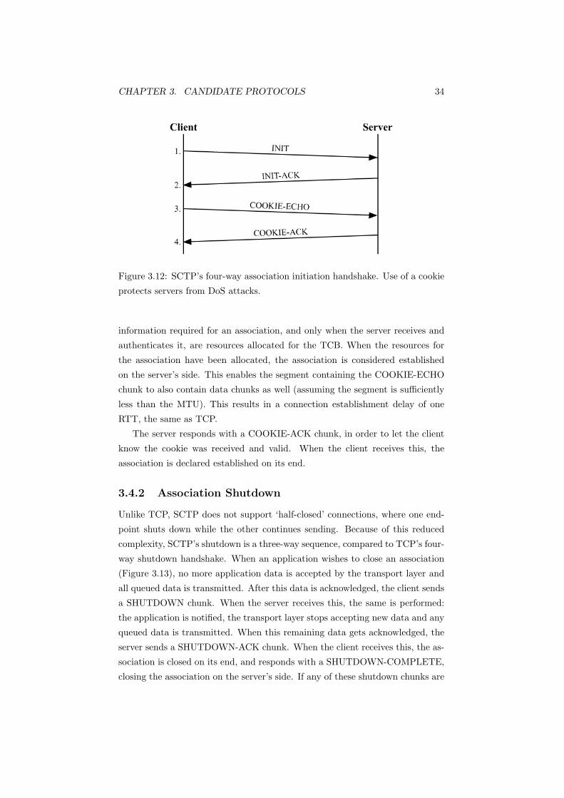
CHAPTER 3. CANDIDATE PROTOCOLS 34
Figure 3.12: SCTP’s four-way association initiation handshake. Use of a cookie
protects servers from DoS attacks.
information required for an association, and only when the server receives and
authenticates it, are resources allocated for the TCB. When the resources for
the association have been allocated, the association is considered established
on the server’s side. This enables the segment containing the COOKIE-ECHO
chunk to also contain data chunks as well (assuming the segment is sufficiently
less than the MTU). This results in a connection establishment delay of one
RTT, the same as TCP.
The server responds with a COOKIE-ACK chunk, in order to let the client
know the cookie was received and valid. When the client receives this, the
association is declared established on its end.
3.4.2 Association Shutdown
Unlike TCP, SCTP does not support ‘half-closed’ connections, where one end-
point shuts down while the other continues sending. Because of this reduced
complexity, SCTP’s shutdown is a three-way sequence, compared to TCP’s four-
way shutdown handshake. When an application wishes to close an association
(Figure 3.13), no more application data is accepted by the transport layer and
all queued data is transmitted. After this data is acknowledged, the client sends
a SHUTDOWN chunk. When the server receives this, the same is performed:
the application is notified, the transport layer stops accepting new data and any
queued data is transmitted. When this remaining data gets acknowledged, the
server sends a SHUTDOWN-ACK chunk. When the client receives this, the as-
sociation is closed on its end, and responds with a SHUTDOWN-COMPLETE,
closing the association on the server’s side. If any of these shutdown chunks are

CHAPTER 3. CANDIDATE PROTOCOLS 35
lost, they are simply retransmitted.
Figure 3.13: SCTP’s shutdown sequence. Unlike TCP, closing an SCTP associ-
ation closes it on both ends.
3.4.3 Implementations and Development
SCTP has kernel implementations5 on Linux, Free/Open BSD, NetBSD, Solaris
as well as many user space implementations. Many products currently use
SCTP, with most of these being commercial SS7 signalling platforms; Cisco,
Hewlett-Packard among others [53] have SCTP-based products to transport SS7
traffic over IP. Several end user applications6 exist which have implemented
SCTP, such as Mozilla and Apache. Unfortunately the Mozilla available for
download supports only SCTP, therefore its usefulness is extremely limited as
SCTP is not widely supported in webservers.
SCTP features in many research topics; current areas of research are de-
scribed in [6, 71, 53, 113].
Like TCP, SCTP can be secured with IPsec [25] and TLS [72]. RFC 3554
describes IPsec support for SCTP’s multihoming addresses. RFC 3436 describes
TLS over SCTP, enabling applications over TLS to use multistreaming and
multihoming. Other efforts to secure SCTP exist, such as Secure SCTP (S-
SCTP)[64] and Datagram Transport Layer Security7 for SCTP[63].
S-SCTP exists to overcome the scalability problems when TLS or IPsec
is used. With TLS, each stream requires its own tunnel. Use of TLS also
prohibits the use of several SCTP options, such as unordered delivery and partial
reliability. With IPsec, a security association (SA) must be created for each IP
address for multihoming. These will be discussed in Section 4.5http://www.sctp.org/implementations.html6http://www.sctp.org/download.html7Datagram Transport Layer Security (DTLS) is a variant of TLS for use with datagrams
and is defined in RFC 4347.
CHAPTER 3. CANDIDATE PROTOCOLS 36
SCTP itself is still being optimised, with updates to its checksum algorithm
[116], as well as an Implementers Guide [112]. SCTP options and extensions
are also being developed:
Partial Reliability Extension ([42]): This enables SCTP to provide an un-
reliable, unordered service akin to UDP, as well as an ordered, unreliable
service.
Dynamic Address Reconfiguration ([92]): This allows adding network in-
terface cards without restarting the SCTP association.
Authenticated Chunks ([77]): Each SCTP packet contains a 32-bit verifi-
cation tag (set to the same value as the initiation tag during association
establishment) to help protect against blind ‘man-in-the-middle’ and se-
quence number attacks. It is also used to verify whether a packet belongs
to the current association or a previous one. Authenticated chunks allow
the sender to sign chunks, so the receiver can verify the authenticity of
the sender and the data. It goes one step further than TLS, as TLS only
secures application data.
PAD Chunk ([78]): This enables SCTP to discover the path MTU.
While SCTP has many attractive features and can be used in place of TCP
(for example for a web browser), it is not a replacement for TCP. Previous work
found that SCTP had lower overall raw throughput and higher latency than
TCP [93]. SCTP’s minimum retransmission timeout, a recommended value
of 1000ms, was deemed too high and was considered a contributing factor to
the slower performance. Another reason was that SCTP’s message orientation
(via chunks) added overhead. This overhead, however, becomes proportionately
smaller when message size is increased, thus reducing the negative impact on
SCTP performance.
When SCTP used only one stream, the performance was lower than TCP.
However, when multiple streams were used, SCTP was able to outperform TCP.
As packet loss and network latency increased, the throughput gap between
TCP and SCTP narrowed, and in some circumstances, the throughput and
resulting latency equalled or exceeded that of TCP. Despite having lower per-
formance (higher latency and lower throughput) than TCP, SCTP realises its
original purpose, of providing a reliable transport for SS7 traffic.

CHAPTER 3. CANDIDATE PROTOCOLS 37
3.4.4 Summary
SCTP’s original purpose was to transport SS7 signalling messages over IP. Such
a transport needed to meet the rigid timing and reliability requirements of PSTN
signalling. Both the main transport protocols, TCP and UDP, have limitations
which make them unsuitable for telephony signalling. SCTP was developed to
address these limitations, however SCTP’s features mean it is not limited to
this scope and it is considered a general-purpose transport protocol.
SCTP’s congestion and flow control are derived from TCP and is message
oriented like UDP. SCTP improves reliability and resilience by supporting mul-
tihoming and a heartbeat system to detect link failures. SCTP avoids HoL
blocking via multistreaming and out of order delivery. Another improvement
over TCP is SCTP’s four-way handshake initiation; SCTP has protection from
SYN-flood type DoS attacks integrated into the protocol, the same as TCP’s
SYN cookies. SCTP can also be secured with several security architectures,
including IPsec and TLS.
Implementations exist on several operating systems and SCTP is deployed
in commercial SS7 signalling architectures. It also features in many research
projects and continues to be refined and developed.
Given the features it brings, and in part combining the functionality of TCP
and UDP, SCTP is a suitable candidate transport layer protocol for a secure
transaction network.
3.5 Quick Transaction Protocol (QTP)
Quick Transaction Protocol (QTP) is a protocol designed specifically for mul-
tiplexing a high volume of short duration transactions (such as EFTPOS) over
IP. The requirements of an application such as EFTPOS are in Section 2.6, and
QTP meets these particular requirements well (the QTP specification was in fact
used in part to create these requirements). QTP, created by Alcatel, Ascend
(now Lucent) and INETCO [3], is not an RFC and remains as an IETF draft
[43]. QTP behaves closest as a session layer protocol, however does not fit neatly
into that classification as it implements some transport layer functionality as
well.
Because QTP is designed for low latency message transfer, UDP is the pre-
ferred transport protocol. QTP, however, can be run over TCP, as it is indepen-
dent of the transport layer. The specification assumes there is a Network Access
Server (NAS) between terminals and the transaction processor (Figure 3.14),
however terminals can have a direct connection to the network server. Termi-

CHAPTER 3. CANDIDATE PROTOCOLS 38
nals usually initiate sessions to the transaction processors, however transaction
processors can also initiate connections to terminals. Reasons for this include
requesting audit information from terminals, or sending stolen “hot card” lists
to terminals [43].
Figure 3.14: QTP assumes a Network Access Server is positioned between Trans-
action Terminals and Transaction Processors. QTP also permits Terminals to
connect directly to the Transaction Processor.
Each logical connection is a QTP session operating over UDP, using a single
port. Using UDP has the benefits of message orientation (as opposed to stream
oriented as TCP is) and low overhead (UDP is a lightweight protocol and does
not require a connection establishment or teardown phase as TCP does).
When an application uses UDP for its performance and simplicity, but re-
quires reliability and congestion control, the application must implement its
own transmission and flow control mechanisms, and QTP is an example of this.
QTP achieves reliability over UDP (or other unreliable transports, as QTP is
transport independent) with request-response message pairs.
QTP also has a rudimentary flow control system as part of its network
status mechanism. Flow control in QTP refers to “the ability of a QTP entity
to service further transactions with a remote QTP Entity” [43], unlike in TCP
and SCTP, which refers to changing the sending rate when network congestion
causes packet loss. A QTP entity has four states:
Available: operational and able to accept new QTP sessions.
Partially Congested: is nearing capacity, but can still accept new QTP ses-
sions.
Congested: at capacity and unable to accept new QTP sessions. Existing
sessions can continue without interruption however.
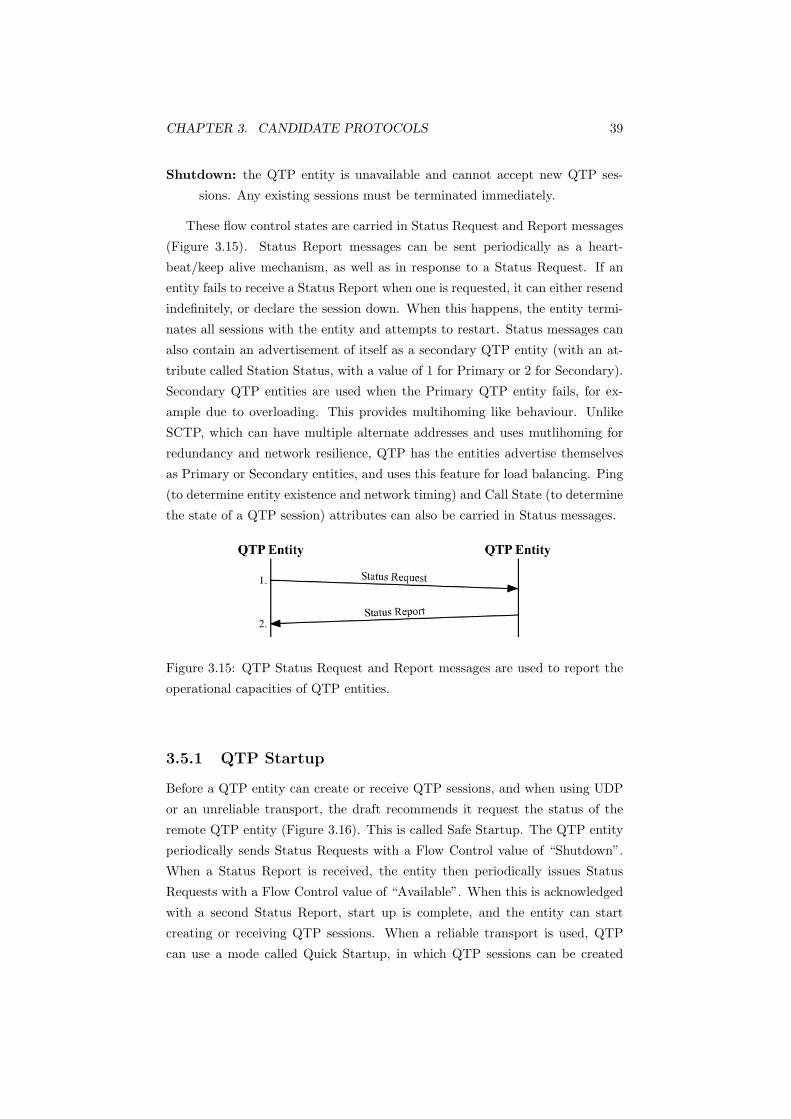
CHAPTER 3. CANDIDATE PROTOCOLS 39
Shutdown: the QTP entity is unavailable and cannot accept new QTP ses-
sions. Any existing sessions must be terminated immediately.
These flow control states are carried in Status Request and Report messages
(Figure 3.15). Status Report messages can be sent periodically as a heart-
beat/keep alive mechanism, as well as in response to a Status Request. If an
entity fails to receive a Status Report when one is requested, it can either resend
indefinitely, or declare the session down. When this happens, the entity termi-
nates all sessions with the entity and attempts to restart. Status messages can
also contain an advertisement of itself as a secondary QTP entity (with an at-
tribute called Station Status, with a value of 1 for Primary or 2 for Secondary).
Secondary QTP entities are used when the Primary QTP entity fails, for ex-
ample due to overloading. This provides multihoming like behaviour. Unlike
SCTP, which can have multiple alternate addresses and uses mutlihoming for
redundancy and network resilience, QTP has the entities advertise themselves
as Primary or Secondary entities, and uses this feature for load balancing. Ping
(to determine entity existence and network timing) and Call State (to determine
the state of a QTP session) attributes can also be carried in Status messages.
Figure 3.15: QTP Status Request and Report messages are used to report the
operational capacities of QTP entities.
3.5.1 QTP Startup
Before a QTP entity can create or receive QTP sessions, and when using UDP
or an unreliable transport, the draft recommends it request the status of the
remote QTP entity (Figure 3.16). This is called Safe Startup. The QTP entity
periodically sends Status Requests with a Flow Control value of “Shutdown”.
When a Status Report is received, the entity then periodically issues Status
Requests with a Flow Control value of “Available”. When this is acknowledged
with a second Status Report, start up is complete, and the entity can start
creating or receiving QTP sessions. When a reliable transport is used, QTP
can use a mode called Quick Startup, in which QTP sessions can be created
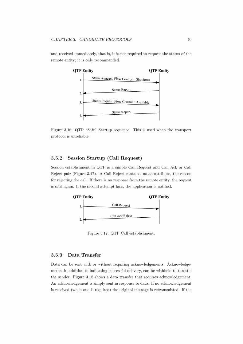
CHAPTER 3. CANDIDATE PROTOCOLS 40
and received immediately, that is, it is not required to request the status of the
remote entity; it is only recommended.
Figure 3.16: QTP “Safe” Startup sequence. This is used when the transport
protocol is unreliable.
3.5.2 Session Startup (Call Request)
Session establishment in QTP is a simple Call Request and Call Ack or Call
Reject pair (Figure 3.17). A Call Reject contains, as an attribute, the reason
for rejecting the call. If there is no response from the remote entity, the request
is sent again. If the second attempt fails, the application is notified.
Figure 3.17: QTP Call establishment.
3.5.3 Data Transfer
Data can be sent with or without requiring acknowledgements. Acknowledge-
ments, in addition to indicating successful delivery, can be withheld to throttle
the sender. Figure 3.18 shows a data transfer that requires acknowledgement.
An acknowledgement is simply sent in response to data. If no acknowledgement
is received (when one is required) the original message is retransmitted. If the
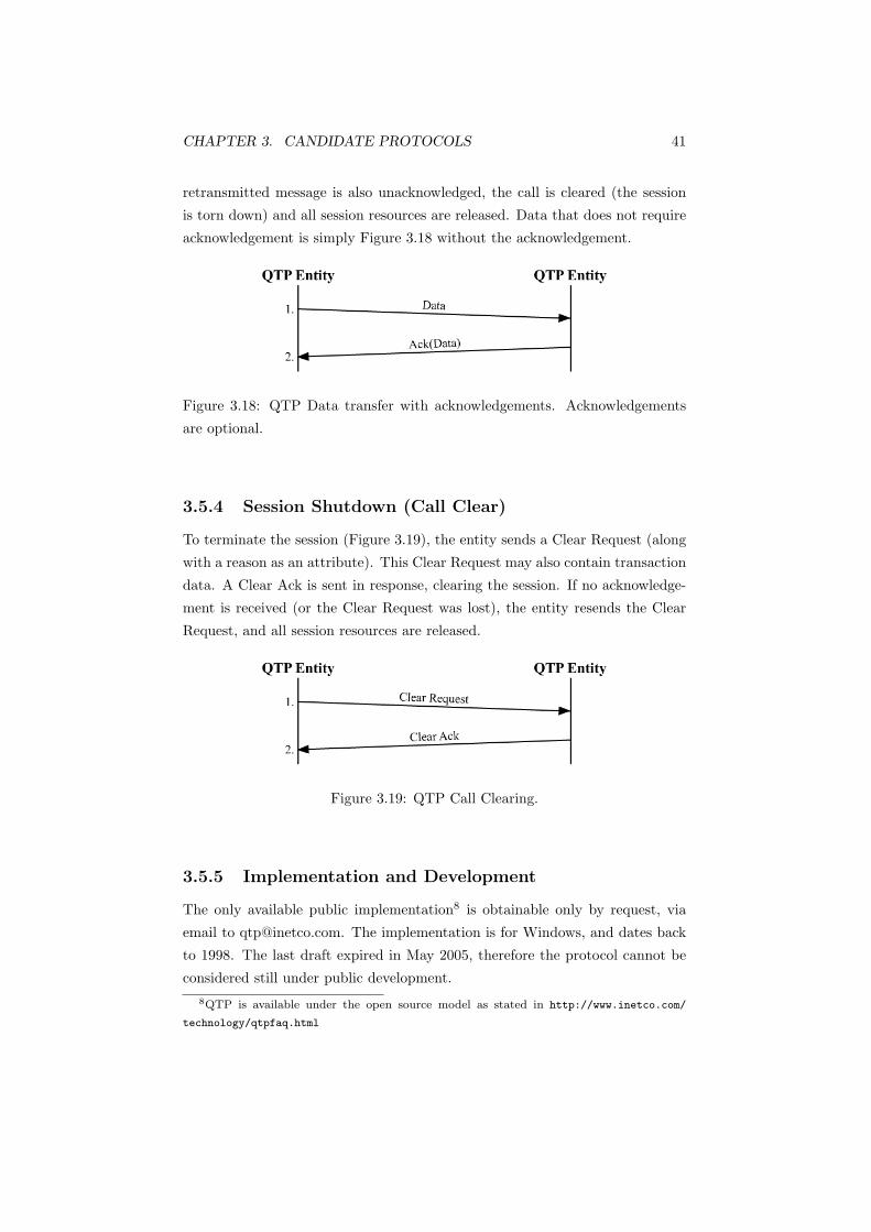
CHAPTER 3. CANDIDATE PROTOCOLS 41
retransmitted message is also unacknowledged, the call is cleared (the session
is torn down) and all session resources are released. Data that does not require
acknowledgement is simply Figure 3.18 without the acknowledgement.
Figure 3.18: QTP Data transfer with acknowledgements. Acknowledgements
are optional.
3.5.4 Session Shutdown (Call Clear)
To terminate the session (Figure 3.19), the entity sends a Clear Request (along
with a reason as an attribute). This Clear Request may also contain transaction
data. A Clear Ack is sent in response, clearing the session. If no acknowledge-
ment is received (or the Clear Request was lost), the entity resends the Clear
Request, and all session resources are released.
Figure 3.19: QTP Call Clearing.
3.5.5 Implementation and Development
The only available public implementation8 is obtainable only by request, via
email to [email protected]. The implementation is for Windows, and dates back
to 1998. The last draft expired in May 2005, therefore the protocol cannot be
considered still under public development.8QTP is available under the open source model as stated in http://www.inetco.com/
technology/qtpfaq.html

CHAPTER 3. CANDIDATE PROTOCOLS 42
Several commercial products implement QTP, although likely to be in a
more advanced state than the publicly available implementation from 1998. IN-
ETCO9 System’s BankLink, POSway and INETCO Connect protocol converter
products support QTP. Vcomm’s Vista10 line of network access devices use QTP
to transport EFTPOS over IP based networks (such as GPRS and Ethernet).
Lucent also supports QTP in its MAX TNT dial gateway[3]. These companies
were also contributors to the QTP specification.
As for deployment in current systems, it is used in Telstra’s Argent system
which replaced the Transend network.11 PetroCanada also uses QTP based
systems to transport EFTPOS to backend transaction switches.
Other than the internet draft specification, there is not much public informa-
tion available regarding QTP. This gives the QTP protocol leverage to be used
as a competitive advantage by the companies that conceived it. This and the
specialised application for which QTP was developed has meant the companies
involved in its development have not pursued standardisation. This instils a
somewhat proprietary nature upon QTP, despite the availability of a stagnant
implementation. As stated in Section 2.6, proprietary systems have several
disadvantages. An organisation, which is not partnered with one of QTP’s de-
velopers has no guarantee that its own implementation can interoperate with
existing systems as the protocol was never standardised; extensions may have
been specified but kept private within the developing companies.
3.5.6 Summary
QTP was developed specifically for transporting transactions (such as EFTPOS)
over IP. Consequently it features low latency, reliable message transfer, with flow
control and load balancing mechanisms. QTP is designed to run over UDP in
order to utilise the protocol’s performance benefits. Reliability is built into QTP
itself, however QTP can also run over reliable protocols such as TCP.
A public implementation exists for Windows, however it has not been up-
dated since 1998. Commercial implementations exist, however the products are
produced by companies involved in QTP’s specificiation. Given QTP’s some-
what proprietary nature, it is not aligned with the goals of building an open,
standards based architecture. Consequently, it cannot be considered a suitable
component for this project.9http://www.inetco.com
10http://www.vcomms.com/vista.html11Incidentally QTP was originally designed for the Argent network.
CHAPTER 3. CANDIDATE PROTOCOLS 43
3.6 Session Initiation Protocol (SIP) - RFC 3261
Session Initiation Protocol (SIP) is an application layer protocol used to estab-
lish, modify and terminate multimedia sessions. SIP can operate over TCP and
UDP as well as SCTP [101]. As SIP provides its own reliability and retrans-
mission mechanism, it can operate over unreliable transports such as UDP. Like
QTP, it is an example of implementing reliability at the application layer. Note,
however, that no congestion control is implemented in SIP; SIP is a session layer
protocol, not a transport protocol.
SIP is defined in RFC 3261 [102] and is also extensively described in [32].
Accordingly its operation will only be described briefly.
There are a number of network entities defined by RFC 3261.
User Agents (UA): the two ‘final’ endpoints of a SIP session. Users interact
with each other via user agents, and these may reside in a VoIP or con-
ference application running on a computer or a hardware device such as a
SIP phone.
Redirect Server: in response to invitations, a redirect server responds with a
list of SIP Uniform Resource Identifiers (URIs12) or the address of another
server which may know where the user is located (Figure 3.20). Here, two
invitation requests are sent from the caller; one to the domain server,
Company.com (a redirect server, which responds with the location of the
callee) and one to computer2.company.com.
Proxy Server: a proxy routes requests on behalf of the UA, either to an-
other proxy server, or the destination UA. For example in Figure 3.21,
the domain server (Company.com) is a proxy server. If the user is located
at computer2.company.com, but the invitation request was sent to Com-
pany.com, the invitation would be proxied to computer2. With a proxy
server, the caller only needs to send an invitation to one location. Proxy
servers can also provide mid-call features and enforce policy (for example
limiting the destinations to which calls can be made)
Registrars: accepts REGISTER messages sent periodically from UAs. REG-
ISTER messages notify the registrar of where the user is currently logged
in, for example in Figure 3.22, [email protected] can be contacted at12A SIP URI is used to identify a SIP user, such as sip:[email protected]. Company.com
is the domain of caller’s SIP service provider. URI’s are similar in form to email addresses. A
secure URI, SIPS, also exists (for example sips:[email protected]). A SIPS URI requires
TLS be used to transmit SIP messages.

CHAPTER 3. CANDIDATE PROTOCOLS 44
Figure 3.20: A redirect server returns a list of possible locations where the user
may be. The caller then sends another invitation to where the user is located.
Figure 3.21: A proxy server forwards requests on behalf of the caller.

CHAPTER 3. CANDIDATE PROTOCOLS 45
[email protected]. This binding is stored in the domain’s
location server. A user can register from multiple locations, for example
callee’s voicemail server could also register, so when callee is busy with a
call, incoming call requests can be directed to voicemail.
Figure 3.22: caller registers itself at computer1 with the SIP registrar.
Location Server: While not a SIP entity (as it does not use SIP to commu-
nicate with other SIP servers), location servers are used by a redirect or
a proxy server to determine the location of a user. Registrars use the
location server to store a user’s location. Users can register from multiple
locations, and the location server returns each location when queried.
These servers may be located in one physical server, that is, one server can
potentially play all four roles.
3.6.1 Session Initiation
SIP can operate over UDP, TCP and SCTP, however UDP is most widely used
[33]. Figure 3.23 illustrates the session initiation sequence. The caller sends an
INVITE request to the callee’s SIP URI ([email protected]). This INVITE
request contains information such as the caller, the callee, as well as information
about the type of session. SIP does not actually provide session description
attributes (such as type of media, codec, and bitrate); these attributes are
described using another protocol such as Session Description Protocol (SDP)
for a multimedia conference; a network game may use its own protocol for
example. SIP separates the initiation of a session from its description, thus any
format of session description can be carried in the SIP payload.13
As the caller does not know the location of the callee, or the callee’s domain’s
SIP server, the INVITE is sent to the caller’s SIP server, companyA.com (a
proxy server). CompanyA.com responds with a 100 Trying to the caller. This
13RFC 3261 describes the SIP payload in a SIP message as comparable to an attachment
in an email message.

CHAPTER 3. CANDIDATE PROTOCOLS 46
Figure 3.23: SIP session initiation sequence.
notifies the caller that the INVITE request was received, and is being forwarded
on the caller’s behalf to the destination. If no 100 Trying is received and
an unreliable transport is used, the INVITE would be retransmitted (at the
application layer).
CompanyA.com locates the callee’s SIP server at CompanyB.com (for ex-
ample via DNS). CompanyA.com adds itself as a via attribute in the INVITE,
and proxies the INVITE request to CompanyB.com. The via attribute indicates
that responses should be sent back to this proxy. When the CompanyB.com
proxy receives this, it also responds with a 100 Trying back to CompanyA.com
(this second 100 Trying is not passed back to the caller as it is what RFC 3261
terms a ‘provisional response’). CompanyB.com uses the generically named
location service (possibly provided by a location server) to locate the callee.
CompanyB.com adds itself as another via attribute, and passes the INVITE to
the callee.
The proxy server could also fork the INVITE request. If the callee had regis-
tered itself from more than one location, CompanyB.com could send the INVITE
request to each possible location; this is known as forking. This provides a de-
gree of multihoming, as a single UA can register from multiple locations (these
locations can be logical, for example the secondary network interface card on a
host).
The callee’s UA alerts the user, for example a SIP phone would ring, or a
conferencing application could pop up with a message indicating a user wishes
to start a conference session. The UA responds with a 180 Ringing message,
which is passed back to the caller through the proxies by sending back to the
first address in the via attribute (CompanyB.com removes its via attribute and
passes it to the next via attribute and so on). Being a ‘provisional response’,
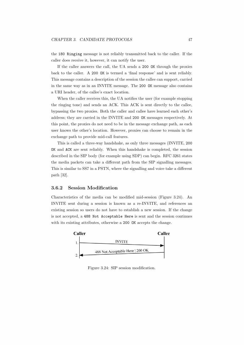
CHAPTER 3. CANDIDATE PROTOCOLS 47
the 180 Ringing message is not reliably transmitted back to the caller. If the
caller does receive it, however, it can notify the user.
If the callee answers the call, the UA sends a 200 OK through the proxies
back to the caller. A 200 OK is termed a ‘final response’ and is sent reliably.
This message contains a description of the session the callee can support, carried
in the same way as in an INVITE message. The 200 OK message also contains
a URI header, of the callee’s exact location.
When the caller receives this, the UA notifies the user (for example stopping
the ringing tone) and sends an ACK. This ACK is sent directly to the callee,
bypassing the two proxies. Both the caller and callee have learned each other’s
address; they are carried in the INVITE and 200 OK messages respectively. At
this point, the proxies do not need to be in the message exchange path, as each
user knows the other’s location. However, proxies can choose to remain in the
exchange path to provide mid-call features.
This is called a three-way handshake, as only three messages (INVITE, 200
OK and ACK are sent reliably. When this handshake is completed, the session
described in the SIP body (for example using SDP) can begin. RFC 3261 states
the media packets can take a different path from the SIP signalling messages.
This is similar to SS7 in a PSTN, where the signalling and voice take a different
path [32].
3.6.2 Session Modification
Characteristics of the media can be modified mid-session (Figure 3.24). An
INVITE sent during a session is known as a re-INVITE, and references an
existing session so users do not have to establish a new session. If the change
is not accepted, a 488 Not Acceptable Here is sent and the session continues
with its existing attributes, otherwise a 200 OK accepts the change.
Figure 3.24: SIP session modification.
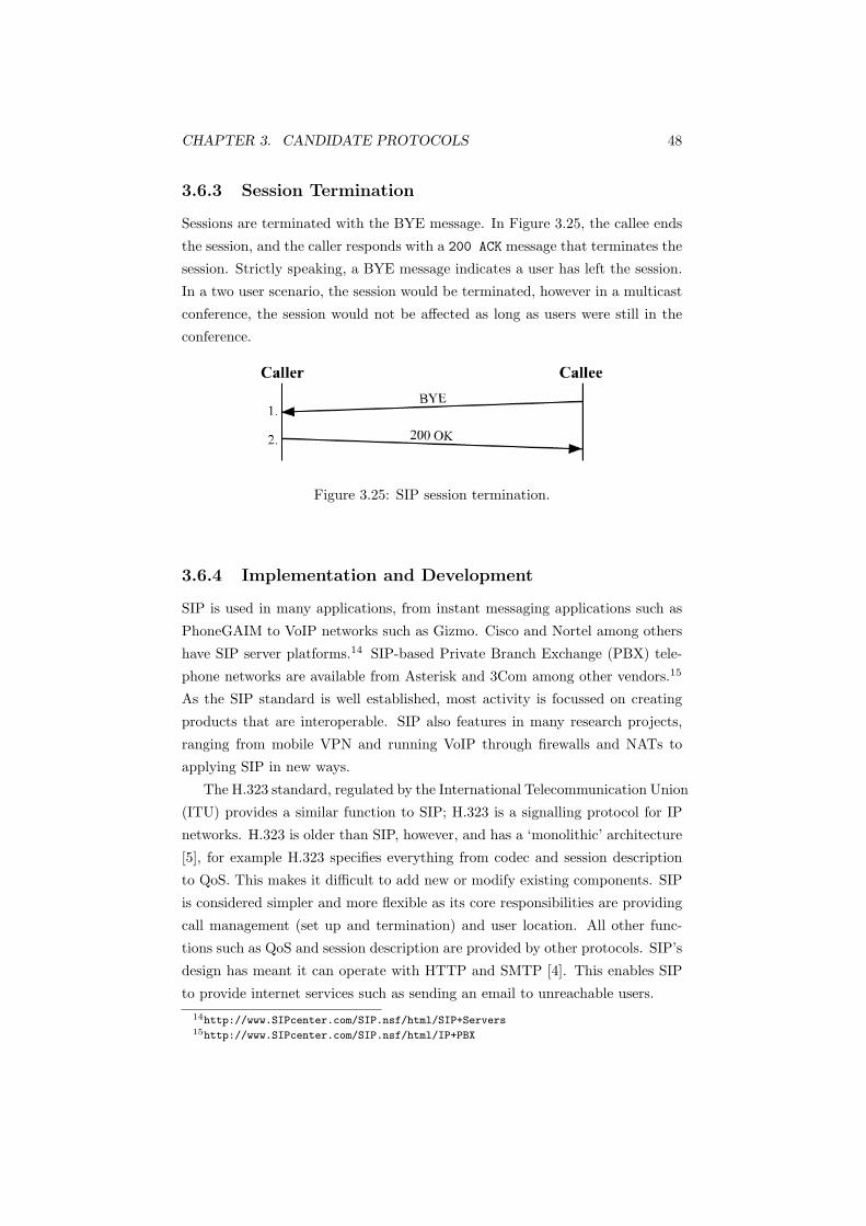
CHAPTER 3. CANDIDATE PROTOCOLS 48
3.6.3 Session Termination
Sessions are terminated with the BYE message. In Figure 3.25, the callee ends
the session, and the caller responds with a 200 ACK message that terminates the
session. Strictly speaking, a BYE message indicates a user has left the session.
In a two user scenario, the session would be terminated, however in a multicast
conference, the session would not be affected as long as users were still in the
conference.
Figure 3.25: SIP session termination.
3.6.4 Implementation and Development
SIP is used in many applications, from instant messaging applications such as
PhoneGAIM to VoIP networks such as Gizmo. Cisco and Nortel among others
have SIP server platforms.14 SIP-based Private Branch Exchange (PBX) tele-
phone networks are available from Asterisk and 3Com among other vendors.15
As the SIP standard is well established, most activity is focussed on creating
products that are interoperable. SIP also features in many research projects,
ranging from mobile VPN and running VoIP through firewalls and NATs to
applying SIP in new ways.
The H.323 standard, regulated by the International Telecommunication Union
(ITU) provides a similar function to SIP; H.323 is a signalling protocol for IP
networks. H.323 is older than SIP, however, and has a ‘monolithic’ architecture
[5], for example H.323 specifies everything from codec and session description
to QoS. This makes it difficult to add new or modify existing components. SIP
is considered simpler and more flexible as its core responsibilities are providing
call management (set up and termination) and user location. All other func-
tions such as QoS and session description are provided by other protocols. SIP’s
design has meant it can operate with HTTP and SMTP [4]. This enables SIP
to provide internet services such as sending an email to unreachable users.14http://www.SIPcenter.com/SIP.nsf/html/SIP+Servers15http://www.SIPcenter.com/SIP.nsf/html/IP+PBX
CHAPTER 3. CANDIDATE PROTOCOLS 49
SIMPLE
The Instant Messaging and Presence Protocol (IMPP) Working Group existed16
to define a generic Instant Messaging and Presence (IM&P) model such that
independently developed instant messaging (IM) applications could interoper-
ate with each other. A document has been produced [44], which specifies the
minimum requirements such a protocol must meet.
The SIP specification (RFC 3261, [102]) contains a rudimentary presence
feature in the form of periodic REGISTER messages. Using this feature for
presence, however, is rather crude as it is not its intended purpose.
The SIP for Instant Messaging and Presence Leveraging Extensions Working
Group (SIMPLE) defines a set of extensions that provides SIP with instant
messaging and a presence service. This is particularly applicable to this project;
instant messages are transferred in real time and the presence service provides a
degree of ‘network intelligence’ (where the presence and availability of a remote
device or peer can be determined). Having knowledge of the network conditions
can improve reliability.
SIMPLE, alongside the XML based Extensible Messaging and Presence Pro-
tocol (XMPP) are the two proposed IMPP’s developed by the IETF [36]. As
[36] explains SIMPLE, it will only be briefly described here.
Presence
Presence in SIMPLE [99] defines a Presence User Agent (PUA), or a presentity
[45] which provides presence information to a presence server (or service). UserB
(a PUA) REGISTERs its current status with the presence server in Figure 3.26
(such as “Available”) upon initialisation, as well as whenever the current status
changes.
UserA wants to know UserB’s current status, and SUBSCRIBES to UserB’s
presence information. Each time UserB’s status changes, the presence server
transmits a NOTIFY to each subscriber. When the subscribers receive this,
they are updated on the user’s current status. This behaviour closely resembles
MQTT as described in Section 2.5, where the presence server is the message
repository and the PUA is the remote device.
Instant Messaging
SIMPLE also defines a MESSAGE method in RFC 3428 [34], where a message
can be contained in a SIP body. A MESSAGE request is treated as a BYE16The group concluded in September 1998.

CHAPTER 3. CANDIDATE PROTOCOLS 50
Figure 3.26: UserA registers to be notified of UserB’s status. When UserB’s
status changes, all subscribers are notified with a NOTIFY message.
request by proxies [32]. The advantage here is existing SIP infrastructure can
be reused to provide IM capabilities without any modification. Figure 3.27
illustrates this.
Figure 3.27: UserA sends an instant message (IM) to UserB.
These extensions to SIP would benefit a transport protocol that is not aware
of its own state of service, such as TCP. While TCP contains a keep alive
function (defined in RFC 1122 [29]), its implementation is optional, as it is not
in the TCP specification (RFC 793 [97]).
Multihoming can also be improved with these extensions; instead of forking
a request to every registered location for a user, a proxy server would only need
to forward requests to where the presentity is declared available. This would
give similar resulting functionality to SCTP’s multihoming, only here it is at
the application layer.

CHAPTER 3. CANDIDATE PROTOCOLS 51
3.6.5 Summary
SIP is an application layer protocol used for session establishment, modification
and termination. SIP is independent of the type of session created and these
sessions can be any type, from voice to video. SIP is part of a modular archi-
tecture, and can therefore be used in conjunction with other services to provide
new functions. SIP has reliability built in and is independent of the transport
protocol, so can operate over unreliable transport protocols.
SIP is currently used in many applications and features in many research
projects, leading to new ways to apply SIP. The SIMPLE extensions are relevant
to this project, as they provide an instant messaging functionality as well as a
degree of network service awareness through the presence facility. The benefit of
providing these services at the application layer is that any transport protocol
can be used to carry SIP.
A lot of activity surrounds SIP and many products will be deployed based
on SIP. SIP is an open protocol, and because of its simplicity, can be easily
extended and applied in many new ways. This flexibility and in particular the
SIMPLE extensions make SIP a worthwhile component for this project.
3.7 Simple Object Access Protocol - SOAP
Simple Object Access Protocol (SOAP) is a protocol based on XML and HTTP
that enables applications to invoke procedures on remote hosts and exchange
information. SOAP is a W3C standard and is up to version 1.2.17 It is part of
the web services architecture [20], comprising SOAP, Web Service Description
Language (WSDL) and the Universal Description, Discovery and Integration
(UDDI) registry.
WSDL uses XML to describe the capabilities and locations of web services,
such as the message format and parameters for the function or method [8].
The interfaces and services described by WSDL may be registered in a UDDI
directory [37]. Businesses can also search for web services in the UDDI directory
service. This enables business partners to share information more efficiently as
interoperability and integration of services is easier; W3CSchools18 uses a flight
reservation example. Airlines register their flight rate and reservation checking
systems into a UDDI directory. Travel Agents then search the directory for an
airline’s interface description. The travel agency can then immediately use the
airline’s interface.17http://www.w3.org/2000/xp/Group18http://www.w3schools.com/wsdl/wsdl uddi.asp
CHAPTER 3. CANDIDATE PROTOCOLS 52
Web services and e-commerce sites are usually built using a three-tier ar-
chitecture: a front end web server, an application server in the middle and a
backend database. As SOAP uses HTTP19, SOAP requests are sent to the or-
ganisation’s web server. These requests are routed to the application server,
where the SOAP processor resides, and parsed.
Frameworks exist so normal applications can be translated into a SOAP
based web application (for example Microsoft’s .NET and Sun’s Enterprise Java
Beans). This makes SOAP requests language independent, as the SOAP request
is translated and parsed by the SOAP/application server into the native lan-
guage. Responses are sent the same way as a SOAP response through the web
server.
As SOAP is based on XML, it is platform independent. The application
frameworks make it language independent as well. These contribute to SOAP’s
interoperability. SOAP uses web servers to communicate, and this can be con-
sidered an advantage. Businesses have experience deploying web servers and
web applications [80] and can utilise existing infrastructure. Firewalls permit
traffic on port 80 so the web server can receive requests. As SOAP uses exist-
ing web servers to communicate, firewalls do not need to open extra ports to
accommodate SOAP; SOAP uses the web server’s opened ports. With other
remote access architectures such as Remote Procedure Call (RPC), Common
Object Request Broker Architecture (CORBA) and Java’s Remote Method In-
vocation (RMI), additional ports on the firewall need to be opened, and this
increases risk. SOAP can operate unimpeded as the firewall sees SOAP requests
as regular web page requests.
However, this behaviour ultimately circumvents the purpose of a firewall.
Since SOAP requests appear as standard web traffic, the firewall now has no way
of determining whether the traffic is a harmless web request, or an application
request message that invokes a function on the server. Firewalls must then
filter at the application layer by inspecting the packet contents. This commonly
happens with email, where potentially harmful attachments are removed from
messages as noted in [20].
While SOAP is a valid architecture for this project, its focus is on interoper-
ability. This project’s goal is to define a protocol stack, which would be employed
universally throughout the entire transaction network. In a controlled deploy-
ment scenario, such as an EFTPOS system, all equipment and infrastructure
would be authorised and sanctioned by the network operator. Consequently,
interoperability problems would be avoided as the entire network would use the19SOAP can also use SMTP

CHAPTER 3. CANDIDATE PROTOCOLS 53
same application layer protocol, in this instance AS2805, as well as the same
underlying network stack (the focus of this project). SOAP’s emphasis on in-
teroperability between different application vendors would be unnecessary in an
environment such as this.
It is conceivable that a payment system such as EFTPOS could be composed
of network infrastructure from different vendors, each using their own payment
card standard. In a relatively uncontrolled situation like this, where the inter-
face used by each vendor is unknown, SOAP would have value. Clients could
determine the interface of the vendor via a UDDI lookup and integrate seam-
lessly. However, allowing unknown devices to integrate into a payment network
and become part of the infrastructure would create security risks.
3.8 Versatile Message Transaction Protocol (VMTP)
- RFC 1045
Versatile Message Transaction Protocol (VMTP) is an experimental transport
protocol, defined in RFC 1045 [38]. VMTP is designed to support RPC and
transaction oriented traffic. Each request and response has a transaction identi-
fier. When a server receives a request, it locates the corresponding transaction
record for the client. If no record exists, the server queries the client to obtain
the necessary information. Thus VMTP establishes connections on demand
[39], and no separate connection establishment phase exists, such as TCP’s 3-
way handshake.
Each network entity has a unique and stable 64-bit identifier that is in-
dependent of the IP address. This facilitates process migration, mobility and
multihoming, as entities are no longer tied to an IP address.
Multicast, datagrams and security are other features of VMTP. Datagrams
in VMTP are simply requests that do not require a response. Acknowledgements
in VMTP are implicit [68]; a response implicitly acknowledges the request, and
a subsequent request implicitly acknowledges the response. VMTP also offers a
streaming mode resulting in similar functionality to TCP. A stream of requests
can be issued with the responses received asynchronously. These responses are
akin to a TCP ACK.
Regardless of these qualities, VMTP cannot be considered a suitable trans-
port protocol; it remains in experimental state and RFC 1045 has not been
updated since February 1988, nor has it been superseded by a newer document.
VMTP perhaps reflects the best practices of the time in terms of protocol de-
sign; it is a function rich protocol, which the RFC states “provides high data

CHAPTER 3. CANDIDATE PROTOCOLS 54
rates, low error rates and relatively low delay”. VMTP can even operate with-
out IP; it can be layered directly on top of a data link layer protocol. It is a
multipurpose protocol, in contrast with modern protocols. Current protocols
are typically single purpose and lightweight, for example SIP and TLS.
3.9 Xpress Transfer Protocol (XTP)
Xpress Transfer Protocol (XTP) combines the functionality of TCP, UDP and
TP4 [121]. While not an IETF RFC, XTP is defined in [10]. It has been adopted
as part of SAFENET, a U.S. military standard for naval network communica-
tions [9]. XTP is not designed as a replacement for TCP, UDP or TP4, but to
work alongside them. XTP, like VMTP, can operate over IP or directly over
the data link layer (for example Ethernet or ATM). XTP is designed to provide
low latency and high throughput for real time systems, for example weapons
control, and generally has higher throughput than TCP [121].
XTP is centred around the separation of error, flow and data transmission
control policies. These three properties can be configured independently of each
other. XTP has three selectable error control modes: reliable (similar to TCP),
unreliable (akin to UDP, where the sender does not receive acknowledgements)
and fast negative acknowledgement. Fast negative acknowledgement means a
receiver, upon identifying out of sequence packets, can immediately inform the
sender of the missing data. The sender then retransmits only the missing data.
This functionality is similar to TCP’s SACK mechanism. Flow control is also
selectable in XTP, and can either be traditional credit windows, a more conser-
vative policy called reservation mode and disabled (used for streaming data, for
example multimedia streams).
A receiver can control the data transmission of a sender by adjusting the rate
and burst parameters. Rate control limits the amount of data that can be sent at
a time while burst control determines the size of data that can be sent. Unlike
conventional flow control which is end-to-end (with no router intervention),
XTP’s flow control can include the routers. This enables a loaded router to
limit the rate of incoming traffic until the network is no longer congested.
XTP features multicast, priority/QoS and fast connection setup. XTP can
achieve with three packets what TCP accomplishes with six. The first packet
opens the connection, contains the data and also closes the connection. The sec-
ond packet contains the response (if any) and the acknowledgement of the close
request and the data. The sender to receiver connection is then closed. The
second packet also contains a close request in the reverse direction. The sender

CHAPTER 3. CANDIDATE PROTOCOLS 55
acknowledges this with a third packet, which closes the receiver to sender con-
nection. XTP also has a two packet exchange for transactions, where the sender
sends a connection request and the data (the transaction request). The receiver
responds with its data (the transaction response) and closes the connection
XTP was developed by the XTP forum, which has since disbanded. The
latest revision of XTP is 4.0b [10] from 1998, and development on the protocol
has stopped. A public implementation was once available from Sandia National
Laboratories, as were commercial implementations from Network Xpress and
Mentat, however these no longer exist; Network Xpress ceased operating in
1999 and Mentat was purchased by Packeteer in late 2004. Accordingly, XTP
is an unsuitable protocol for this project.
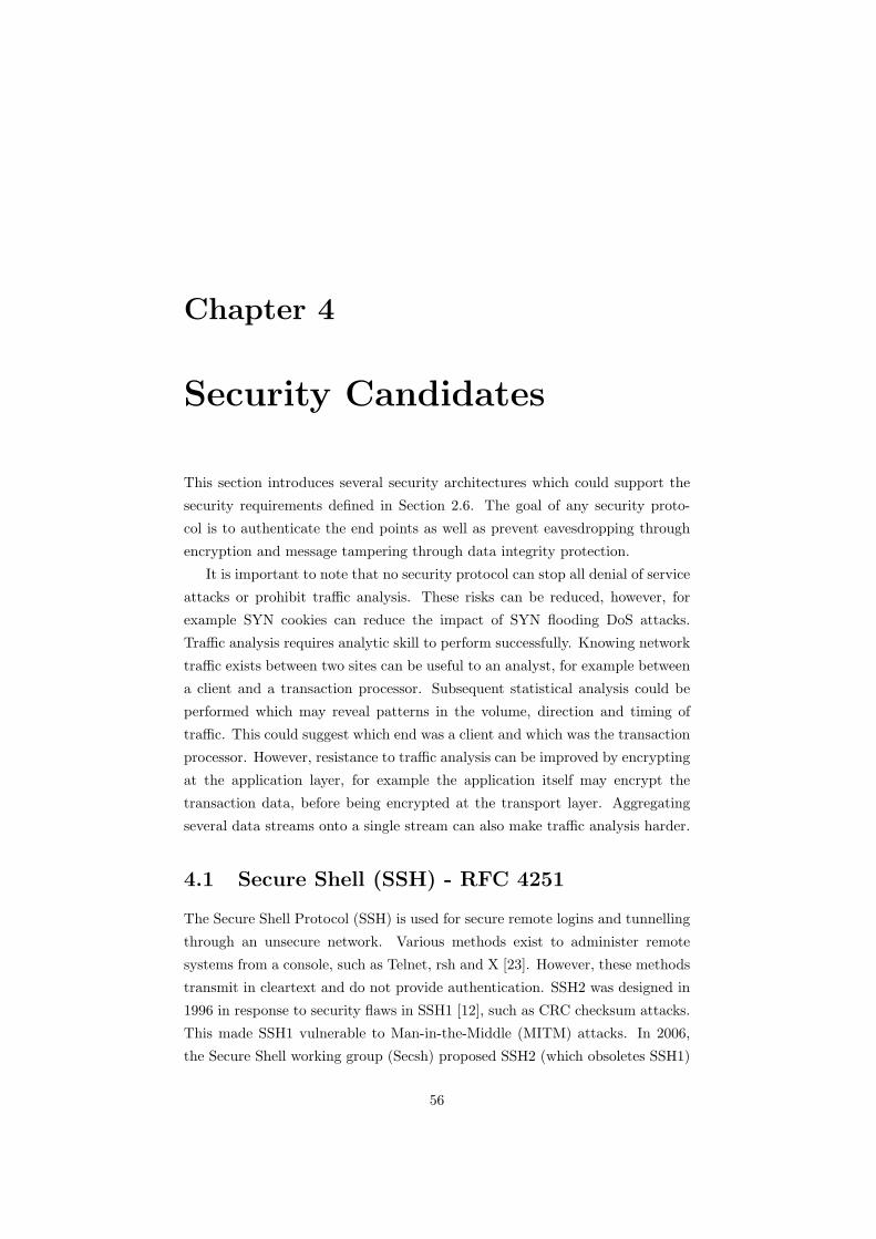
Chapter 4
Security Candidates
This section introduces several security architectures which could support the
security requirements defined in Section 2.6. The goal of any security proto-
col is to authenticate the end points as well as prevent eavesdropping through
encryption and message tampering through data integrity protection.
It is important to note that no security protocol can stop all denial of service
attacks or prohibit traffic analysis. These risks can be reduced, however, for
example SYN cookies can reduce the impact of SYN flooding DoS attacks.
Traffic analysis requires analytic skill to perform successfully. Knowing network
traffic exists between two sites can be useful to an analyst, for example between
a client and a transaction processor. Subsequent statistical analysis could be
performed which may reveal patterns in the volume, direction and timing of
traffic. This could suggest which end was a client and which was the transaction
processor. However, resistance to traffic analysis can be improved by encrypting
at the application layer, for example the application itself may encrypt the
transaction data, before being encrypted at the transport layer. Aggregating
several data streams onto a single stream can also make traffic analysis harder.
4.1 Secure Shell (SSH) - RFC 4251
The Secure Shell Protocol (SSH) is used for secure remote logins and tunnelling
through an unsecure network. Various methods exist to administer remote
systems from a console, such as Telnet, rsh and X [23]. However, these methods
transmit in cleartext and do not provide authentication. SSH2 was designed in
1996 in response to security flaws in SSH1 [12], such as CRC checksum attacks.
This made SSH1 vulnerable to Man-in-the-Middle (MITM) attacks. In 2006,
the Secure Shell working group (Secsh) proposed SSH2 (which obsoletes SSH1)
56
CHAPTER 4. SECURITY CANDIDATES 57
as an IETF proposed standard. The architecture is defined in RFC 4251 [125]
and consists of three main components:
The Secure Shell (SSH) Authentication Protocol (RFC 4252)[123]: This
describes the authentication protocol framework and describes the public
key, password and host-based authentication methods. It runs over the
SSH Transport layer protocol and authenticates the user to the server.
The Secure Shell (SSH) Transport Layer Protocol (RFC 4253)[126]:
This runs over TCP/IP and thus is not a ‘transport layer protocol’ in the
network stack sense. This protocol can provide a secure network service
and offers encryption, data integrity and authentication as well as key ex-
change methods and algorithm negotiation. It provides only host-based
authentication and relies on higher layers for user authentication.
The Secure Shell (SSH) Connection Protocol (RFC4254)[124]: This pro-
vides secure interactive login sessions, remote execution of commands and
forwarding of TCP ports. These different logical channels can be multi-
plexed onto a single secure connection. This also operates over the SSH
transport layer and authentication protocol.
SSH’s port forwarding capability enables it to create secure TCP tunnels
between endpoints. These tunnels can be created on any port, and can therefore
be used to transmit data securely for any TCP application. Tunnels are created
with the -L and -R options, used for local forwarding and remote forwarding
respectively.
Figure 4.1: Anything sent to 127.0.0.1:5000 on the client is forwarded securely
to server:80 by SSH.
Figure 4.1 shows a tunnel created between two hosts. Using local forwarding
(the -L option), the tunnel would have been established on the client with the
command:

CHAPTER 4. SECURITY CANDIDATES 58
client:$ ssh -L 5000:server:80 server
On the client, this command forwards anything directed to localhost (the
client’s 127.0.0.1):5000 to server:80 through the SSH secured tunnel.
Figure 4.2: A tunnel created with the command ssh -L 5000:mailserver:110
server. The traffic is encrypted between client and server, but is in plaintext
between server and the mailserver.
Connections can also be created to hosts behind the SSH server, for example
in Figure 4.2. Using local forwarding again, the tunnel would have been estab-
lished on the client with:
client:$ ssh -L 5000:mailserver:110 server
This command works as follows.
1. Upon typing the command on the client, the SSH client binds to port 5000
on the loopback address 127.0.0.1 on the client
2. When a process on the client connects to 127.0.0.1, the SSH client accepts
the connection
3. The SSH client informs the server through the encrypted tunnel to create
a connection to mailserver:110
4. The SSH client forwards any data directed to 127.0.0.1:5000 to the server
through the encrypted tunnel.
5. The server decrypts the data and forwards the plaintext data to mailserver:110.
6. The mailserver sends responses back to the server in plaintext.
7. The server forwards these through the encrypted tunnel back to the SSH
client.
8. The SSH client on the client decrypts these and sends the plaintext back
to the process.
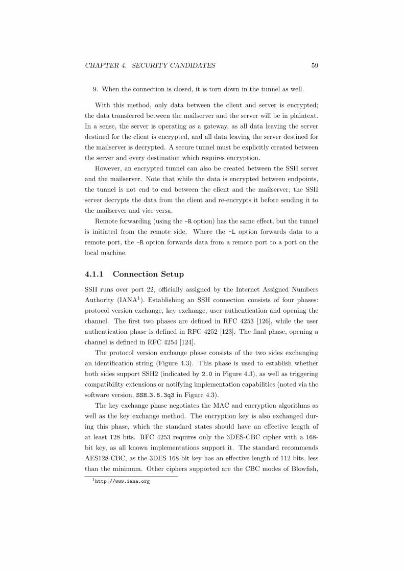
CHAPTER 4. SECURITY CANDIDATES 59
9. When the connection is closed, it is torn down in the tunnel as well.
With this method, only data between the client and server is encrypted;
the data transferred between the mailserver and the server will be in plaintext.
In a sense, the server is operating as a gateway, as all data leaving the server
destined for the client is encrypted, and all data leaving the server destined for
the mailserver is decrypted. A secure tunnel must be explicitly created between
the server and every destination which requires encryption.
However, an encrypted tunnel can also be created between the SSH server
and the mailserver. Note that while the data is encrypted between endpoints,
the tunnel is not end to end between the client and the mailserver; the SSH
server decrypts the data from the client and re-encrypts it before sending it to
the mailserver and vice versa.
Remote forwarding (using the -R option) has the same effect, but the tunnel
is initiated from the remote side. Where the -L option forwards data to a
remote port, the -R option forwards data from a remote port to a port on the
local machine.
4.1.1 Connection Setup
SSH runs over port 22, officially assigned by the Internet Assigned Numbers
Authority (IANA1). Establishing an SSH connection consists of four phases:
protocol version exchange, key exchange, user authentication and opening the
channel. The first two phases are defined in RFC 4253 [126], while the user
authentication phase is defined in RFC 4252 [123]. The final phase, opening a
channel is defined in RFC 4254 [124].
The protocol version exchange phase consists of the two sides exchanging
an identification string (Figure 4.3). This phase is used to establish whether
both sides support SSH2 (indicated by 2.0 in Figure 4.3), as well as triggering
compatibility extensions or notifying implementation capabilities (noted via the
software version, SSH 3.6.3q3 in Figure 4.3).
The key exchange phase negotiates the MAC and encryption algorithms as
well as the key exchange method. The encryption key is also exchanged dur-
ing this phase, which the standard states should have an effective length of
at least 128 bits. RFC 4253 requires only the 3DES-CBC cipher with a 168-
bit key, as all known implementations support it. The standard recommends
AES128-CBC, as the 3DES 168-bit key has an effective length of 112 bits, less
than the minimum. Other ciphers supported are the CBC modes of Blowfish,1http://www.iana.org
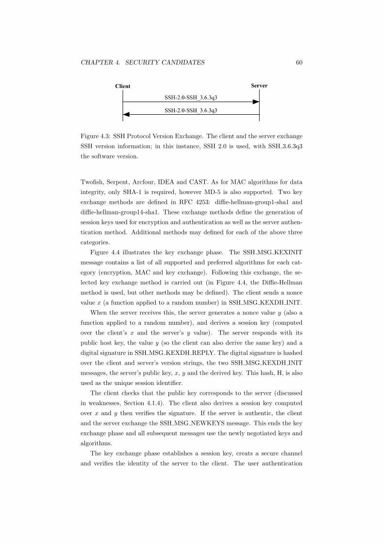
CHAPTER 4. SECURITY CANDIDATES 60
Figure 4.3: SSH Protocol Version Exchange. The client and the server exchange
SSH version information; in this instance, SSH 2.0 is used, with SSH 3.6.3q3
the software version.
Twofish, Serpent, Arcfour, IDEA and CAST. As for MAC algorithms for data
integrity, only SHA-1 is required, however MD-5 is also supported. Two key
exchange methods are defined in RFC 4253: diffie-hellman-group1-sha1 and
diffie-hellman-group14-sha1. These exchange methods define the generation of
session keys used for encryption and authentication as well as the server authen-
tication method. Additional methods may defined for each of the above three
categories.
Figure 4.4 illustrates the key exchange phase. The SSH MSG KEXINIT
message contains a list of all supported and preferred algorithms for each cat-
egory (encryption, MAC and key exchange). Following this exchange, the se-
lected key exchange method is carried out (in Figure 4.4, the Diffie-Hellman
method is used, but other methods may be defined). The client sends a nonce
value x (a function applied to a random number) in SSH MSG KEXDH INIT.
When the server receives this, the server generates a nonce value y (also a
function applied to a random number), and derives a session key (computed
over the client’s x and the server’s y value). The server responds with its
public host key, the value y (so the client can also derive the same key) and a
digital signature in SSH MSG KEXDH REPLY. The digital signature is hashed
over the client and server’s version strings, the two SSH MSG KEXDH INIT
messages, the server’s public key, x, y and the derived key. This hash, H, is also
used as the unique session identifier.
The client checks that the public key corresponds to the server (discussed
in weaknesses, Section 4.1.4). The client also derives a session key computed
over x and y then verifies the signature. If the server is authentic, the client
and the server exchange the SSH MSG NEWKEYS message. This ends the key
exchange phase and all subsequent messages use the newly negotiated keys and
algorithms.
The key exchange phase establishes a session key, creats a secure channel
and verifies the identity of the server to the client. The user authentication
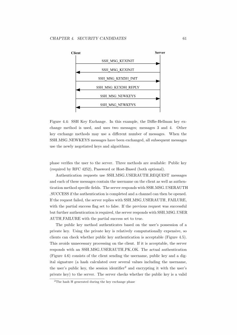
CHAPTER 4. SECURITY CANDIDATES 61
Figure 4.4: SSH Key Exchange. In this example, the Diffie-Hellman key ex-
change method is used, and uses two messages; messages 3 and 4. Other
key exchange methods may use a different number of messages. When the
SSH MSG NEWKEYS messages have been exchanged, all subsequent messages
use the newly negotiated keys and algorithms.
phase verifies the user to the server. Three methods are available: Public key
(required by RFC 4252), Password or Host-Based (both optional).
Authentication requests use SSH MSG USERAUTH REQUEST messages
and each of these messages contain the username on the client as well as authen-
tication method specific fields. The server responds with SSH MSG USERAUTH
SUCCESS if the authentication is completed and a channel can then be opened.
If the request failed, the server replies with SSH MSG USERAUTH FAILURE,
with the partial success flag set to false. If the previous request was successful
but further authentication is required, the server responds with SSH MSG USER
AUTH FAILURE with the partial success set to true.
The public key method authenticates based on the user’s possession of a
private key. Using the private key is relatively computationally expensive, so
clients can check whether public key authentication is acceptable (Figure 4.5).
This avoids unnecessary processing on the client. If it is acceptable, the server
responds with an SSH MSG USERAUTH PK OK. The actual authentication
(Figure 4.6) consists of the client sending the username, public key and a dig-
ital signature (a hash calculated over several values including the username,
the user’s public key, the session identifier2 and encrypting it with the user’s
private key) to the server. The server checks whether the public key is a valid
2The hash H generated during the key exchange phase

CHAPTER 4. SECURITY CANDIDATES 62
authenticator for the user and the validity of the signature. If both succeed and
no further authentication is required, the user is authenticated.
Figure 4.5: The client can check whether public key user authentication is ac-
ceptable, before performing computationally expensive public/private key op-
erations.
Figure 4.6: SSH User Authentication. While the actual content of the messages
are different, the messages exchanged are the same for public key, password and
host based user authentication.
The password method transmits the password in plaintext within the SSH
packet, however all packets are encrypted since the successful key exchange. Fig-
ure 4.6 shows this method. If the password has expired, the server can request
a password change (Figure 4.7) with the SSH MSG USERAUTH PASSWD
CHANGEREQ message. The SSH client can use a different authentication
method or request a new password from the user. The server may respond
with either SSH MSG USERAUTH SUCCESS if the password was changed
successfully and the user is authenticated; SSH MSG USERAUTH FAILURE
with partial success if the password was changed but further authentication is
required; SSH MSG USERAUTH FAILURE without partial success if the pass-
word was not changed due to the server not supporting password changes or the
old password was incorrect; or SSH MSG USERAUTH CHANGEREQ if the
new password is unacceptable (for example being too short).
The host-based authentication method authenticates on the username and
the host the user is connecting from. This method is similar to the public key
method, except it authenticates on the host’s public key rather than the user’s.
The client authenticates by sending the username, hostname, the host’s public

CHAPTER 4. SECURITY CANDIDATES 63
Figure 4.7: If an expired password is used to authenticate a user, the server can
request the user to change the password.
key, the username logged onto the host and a digital signature calculated over
these values and the session identifier (Figure 4.6). The server verifies the host’s
public key and validates the signature to complete authentication. The server
may also check whether the user is authorised to log in.
Keys can be renewed at any time as long as a key exchange is not already
in progress. Rekeying is identical to the initial key exchange with the exception
of creating a new session identifier, which remains the same. The client or the
server can initiate rekeying. RFC 4243 recommends rekeying after 1GB of data
is transferred or one hour, which ever comes first. However, as public/private
key encryption is used during the key exchange, it is computationally expensive,
so should not be performed too frequently.
When the three phases of authentication are complete, a channel can be
opened. Multiple channels are multiplexed on a single tunnel. Figure 4.8 il-
lustrates opening a channel. A channel can be opened from either side, and
in Figure 4.8, the client sends an SSH MSG CHANNEL OPEN message, which
contains a local channel number. The server replies with SSH MSG CHANNEL
OPEN CONFIRMATION or SSH MSG CHANNEL OPEN FAILURE with a
reason code of either:
• SSH OPEN ADMINISTRATIVELY PROHIBITED
• SSH OPEN CONNECT FAILED
• SSH OPEN UNKNOWN CHANNEL TYPE
• SSH OPEN RESOURCE SHORTAGE
When a channel is opened, data transfer can begin using the SSH MSG CHANNEL
DATA message.
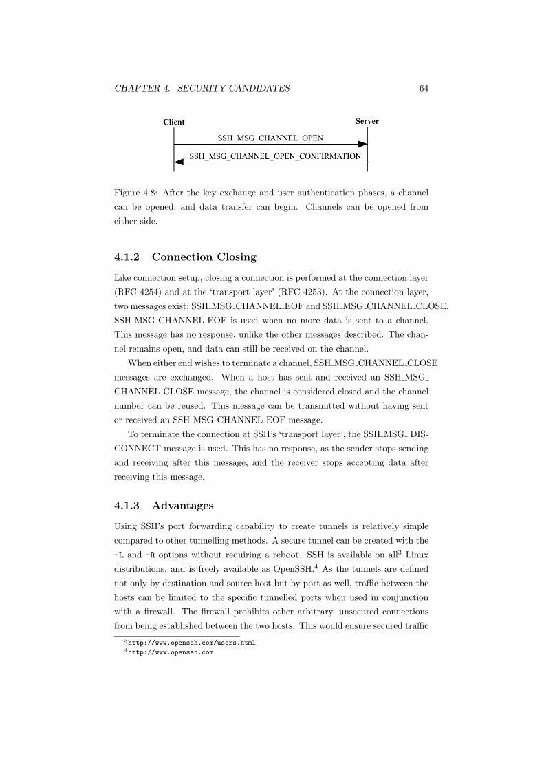
CHAPTER 4. SECURITY CANDIDATES 64
Figure 4.8: After the key exchange and user authentication phases, a channel
can be opened, and data transfer can begin. Channels can be opened from
either side.
4.1.2 Connection Closing
Like connection setup, closing a connection is performed at the connection layer
(RFC 4254) and at the ‘transport layer’ (RFC 4253). At the connection layer,
two messages exist; SSH MSG CHANNEL EOF and SSH MSG CHANNEL CLOSE.
SSH MSG CHANNEL EOF is used when no more data is sent to a channel.
This message has no response, unlike the other messages described. The chan-
nel remains open, and data can still be received on the channel.
When either end wishes to terminate a channel, SSH MSG CHANNEL CLOSE
messages are exchanged. When a host has sent and received an SSH MSG
CHANNEL CLOSE message, the channel is considered closed and the channel
number can be reused. This message can be transmitted without having sent
or received an SSH MSG CHANNEL EOF message.
To terminate the connection at SSH’s ‘transport layer’, the SSH MSG DIS-
CONNECT message is used. This has no response, as the sender stops sending
and receiving after this message, and the receiver stops accepting data after
receiving this message.
4.1.3 Advantages
Using SSH’s port forwarding capability to create tunnels is relatively simple
compared to other tunnelling methods. A secure tunnel can be created with the
-L and -R options without requiring a reboot. SSH is available on all3 Linux
distributions, and is freely available as OpenSSH.4 As the tunnels are defined
not only by destination and source host but by port as well, traffic between the
hosts can be limited to the specific tunnelled ports when used in conjunction
with a firewall. The firewall prohibits other arbitrary, unsecured connections
from being established between the two hosts. This would ensure secured traffic3http://www.openssh.com/users.html4http://www.openssh.com

CHAPTER 4. SECURITY CANDIDATES 65
is permitted traffic.
SSH can also be used to tunnel all traffic between two hosts, by tunnelling
PPP over SSH. However, this is not considered an efficient VPN solution [24, 31].
4.1.4 Drawbacks
The architectural defects of SSH are investigated in [103]. One flaw identified
is the key management mechanism. SSH has the concept of a certification au-
thority (CA) to verify the authenticity of remote servers, however no widely
deployed key infrastructure is available [125]. The host key of a server cannot
be authenticated when a client connects to it for the first time, so clients cannot
be sure if the server is authentic. When users connect to a remote server for the
first time, they are presented with the following:
client:$ ssh server.company.com
The authenticity of host ’server.company.com (123.123.123.123)’ can’t
be established.
RSA key fingerprint is 86:e0:c0:f9:e8:2b:df:c6:1f:f4:bb:d9:13:2d:47:11.
Are you sure you want to continue connecting (yes/no)? yes
Warning: Permanently added ’server.company.com,123.123.123.123’ (RSA)
to the list of known hosts.
user@client’s password:
client:$
When the user types ‘yes’, the key is saved to $HOME/.ssh/knownhosts.
On all subsequent connections, the fingerprint of the remote host is compared
with the entry in the knownhosts file. It is up to the user to determine the
authenticity of remote hosts; the knownhosts file is essentially the user’s own CA
[61]. Users can verify the authenticity of the host key via out of band methods
(for example publishing the key fingerprints on a private webpage). Failing that,
users can also compare the key fingerprint of the host after they have logged on,
with the fingerprint presented. If the user was able to successfully connect to
an intruder, however, it is likely their password has been compromised. Clients
connecting to an intruder masquerading as a legitimate server form the basis of
a ‘Man-in-the-Middle’ attack.
The option of not checking the remote server host key on the initial connec-
tion reduces the security of the protocol. Unfortunately this option is required
as no key verification infrastructure exists, and the Secsh working group consider
the ease of use critical to user acceptance of new security solutions.

CHAPTER 4. SECURITY CANDIDATES 66
The password user authentication method was also identified as vulnerable in
[103], assuming clients connected to a fake server. SSH exchanges keys before the
user is authenticated, so the intruder would be able obtain the user’s password.
This is because the password would have been encrypted using a session key
negotiated between the client and the intruder. Again, this rests on the client
being unable to verify whether the server was authentic in the first place, and
connecting regardless.
The public key authentication method however is not vulnerable to this flaw.
The server authenticates the user’s public key with a valid user and checks the
validity of the signature before authenticating the user. An intruder would not
be able to carry out an attack as:
• The intruder’s public key would not correspond to a valid user or;
• The signature would be computed over the client’s username, public key
and the negotiated session key between the client and the intruder, then
encrypted with the client’s private key. When using the victim’s (client)
public key, a valid signature would not be created, as the intruder must
compute the signature over the session key between the intruder and the
server, not the session key between the client and the intruder. This would
then need to be encrypted with the client’s private key, which the intruder
does not have.
Finally a flaw in the authentication method negotiation was identified in
[103]. If both the server and client cannot agree on an authentication method,
the connection is closed. The server could then force the client to use an arbi-
trary method (such as the password method) of the server’s choice if the user
wanted to keep the connection.
Essentially these flaws rely on a user connecting to an intruder instead of the
server. If users are vigilant and verify the fingerprint of the server’s key before
connecting the MITM attacks described would not be possible.
A disadvantage of using SSH tunnels is that only TCP traffic can be tun-
nelled securely; UDP applications cannot be used.
4.1.5 Implementations and Development
SSH is available from SSH Communications Security5 as a commercial product.
As a proposed internet standard, SSH requires at least one free implementation5http://www.ssh.com

CHAPTER 4. SECURITY CANDIDATES 67
and this exists as OpenSSH.6 OpenSSH is developed by the OpenBSD devel-
opers and has been part of OpenBSD since version 2.6. OpenBSD has a strict
source code auditing process, ensuring the security of the operating system. Se-
curity problems are fully disclosed, enabling rapid fixes, usually within an hour.7
Being part of OpenBSD, OpenSSH is subject to the rigorous auditing process
as well. Both OpenSSH and OpenBSD are open source projects, and have the
benefits as stated in Section 2.6.
4.1.6 Summary
SSH provides a secure method to administer remote systems. SSH can be used
to create secured TCP tunnels between two hosts via port forwarding. This
allows secure traffic for any TCP application. Establishing tunnels is simple
and the OpenSSH implementation is freely available. As OpenSSH is open
source, public code reviews ensure security flaws are rectified promptly.
Flaws in SSH rely on the user’s inability to verify the authenticity of remote
servers and consequently connecting to fake servers. Following this, if password
authentication is used, the intruder can obtain the user’s password. However,
this can be prevented when public key authentication is used. MITM attacks are
only possible when users connect and authenticate themselves to fake servers.
Methods are available to verify the identity of a remote server before connecting,
making MITM attacks preventable. SSH provides a simple, secure means of
creating encrypted TCP channels and is a candidate tunnelling method.
4.2 IP Security (IPsec) - RFC 4301
IPsec defines a security architecture for the internet protocol in RFC 4301 [75].
IPsec is a widely deployed architecture for securing traffic over a public net-
work and is well researched. Consequently, its features and capabilities are not
introduced or described here. Section 3 of RFC 4301 [75] contains a sufficient
overview.
Network Address Translation (NAT) can cause problems for IPsec [67].
When IPsec is operating in AH mode, the source address is hashed with other
data for data integrity. When the packet passes through a NAT device, the
source address will be changed. When the IPsec host receives this and validates
its integrity, the resulting hash will be different and the packet will be blocked
or dropped as it appears modified. IPsec can use ESP to traverse a NAT device,6http://www.openssh.com7http://www.openbsd.org/security.html
CHAPTER 4. SECURITY CANDIDATES 68
as the encapsulated source address is not changed by the NAT device; only the
outer source address is modified.
4.2.1 Establishing a Security Association (SA)
The Internet Key Exchange Protocol version 2 (IKEv2) is the default protocol
used by IPsec for automated key management and authentication. RFC 4306
[74] defines IKEv2. IKEv2 does not interoperate with IKEv1, however they both
run over UDP port 500. This is actually an advantage, as it is impossible for
IKEv2 to negotiate or roll back to IKEv1. This means flaws and vulnerabilities
in IKEv1, which IKEv2 fixed, can no longer be exploited.
A Security Association (SA) is a unidirectional link secured by Authen-
tication Header (AH) or Encapsulating Security Payload (ESP). To secure a
connection, two SAs (one in each direction) are required and IKE creates SAs
in pairs for this.
Messages are exchanged in pairs; a request and a response. The first two
pairs of messages exchanged are the IKE SA INIT and IKE AUTH messages.
These four messages are enough to create the IKE SA and the first CHILD SA
and are known as Phase 1 in IKEv1. A CHILD SA is created through the
IKE SA, and represents a connection secured by AH or ESP.
Figure 4.9 illustrates the basic exchange. The initiator sends the first IKE SA
INIT message. This message contains the cryptographic algorithms supported
by the initiator, their Diffie-Hellman value and a nonce value. IKEv2 is required
to support at least 3DES-CBC and AES-128-CBC for encryption, and HMAC-
SHA-96 and AES-XCBC-MAC-96 for integrity [62]. IKEv2 may also support
HMAC-MD5-96 for data integrity [106].
The responder replies with an IKE SA INIT message. This message contains
the responder’s choice of algorithms selected from the initiator’s list as well as
the responder’s Diffie-Hellman value and nonce. This message may also request a
certificate from the initiator. At this point, both sides can generate SKEYSEED
from the nonces and the Diffie-Hellman values. All other keys are derived from
SKEYSEED, and subsequent messages are encrypted and integrity protected.
The second pair of messages sent are IKE AUTH messages. This exchange
authenticates the previous two messages, authenticates identities and establishes
the first (and often only) CHILD SA. Identities are authenticated using one of
three methods: a pre-shared key (PSK); a digital signature generated from a
certificate issued by a CA; or a digital signature created from a self-generated
public/private key pair. Each peer the initiator intends to communicate with
must be configured with the PSK or public key when using a PSK or self-

CHAPTER 4. SECURITY CANDIDATES 69
Figure 4.9: IKE SA and CHILD SA negotiation. These four message estab-
lish the IKE SA and the first CHILD SA. The first pair of messages negotiate
algorithms and exchange nonces and Diffie-Hellman values. The IKE AUTH
messages are integrity protected and encrypted, as are subsequent messages
(denoted by the {}).
generated key respectively. Consequently, these two methods do not scale well.
The initiator sends its authenticated identity, and 2 digital signatures; one
for the current message (encrypted with the session MAC key), and one for the
first message (encrypted with the private key). Traffic selectors8 and an SA
offer are also sent to start negotiation of the CHILD SA. An SA offer lists the
algorithm suites supported for the CHILD SA. ESP is required to support at
least 3DES-CBC, but may also support AES-128-CBC [49]. RFC 4305 requires
DES-CBC not to be supported, as it is no longer secure. HMAC-SHA1-96
is the only required data integrity algorithm required by ESP, however AES-
XCBC-MAC-96 and HMAC-MD5-96 are also supported. ESP also supports
combined mode algorithms, which provide both encryption and data integrity.
Combined mode algorithms can improve throughput and efficiency and may be
required in ESP in the future. An example is AES-CCM; it is already used in
WPA2/IEEE 802.11i [16] to secure wireless networks. AH has the same data
integrity algorithm support as ESP.
The initial IKE AUTH message may also contain the initiator’s certificate
and a list of trusted CAs - this is essentially a request for the responder’s certifi-
cate. The digital signature used to verify integrity of the first message may be
a private or shared key integrity code. The key used to generate the signature
is associated with the identity of the sender (for example their private key).
The response contains the responder’s identity (which is also authenticated
by means of a pre-shared or a digital signature), a certificate (if required) and a
8These define the protocol carried in the SA, for example TCP, UDP and the start and
end ports
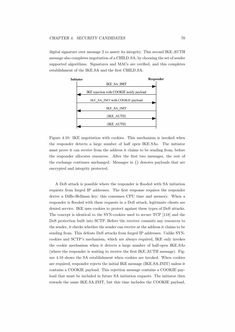
CHAPTER 4. SECURITY CANDIDATES 70
digital signature over message 2 to assert its integrity. This second IKE AUTH
message also completes negotiation of a CHILD SA, by choosing the set of sender
supported algorithms. Signatures and MACs are verified, and this completes
establishment of the IKE SA and the first CHILD SA.
Figure 4.10: IKE negotiation with cookies. This mechanism is invoked when
the responder detects a large number of half open IKE SAs. The initiator
must prove it can receive from the address it claims to be sending from, before
the responder allocates resources. After the first two messages, the rest of
the exchange continues unchanged. Messages in {} denotes payloads that are
encrypted and integrity protected.
A DoS attack is possible where the responder is flooded with SA initiation
requests from forged IP addresses. The first response requires the responder
derive a Diffie-Hellman key; this consumes CPU time and memory. When a
responder is flooded with these requests in a DoS attack, legitimate clients are
denied service. IKE uses cookies to protect against these types of DoS attacks.
The concept is identical to the SYN-cookies used to secure TCP [118] and the
DoS protection built into SCTP. Before the receiver commits any resources to
the sender, it checks whether the sender can receive at the address it claims to be
sending from. This defeats DoS attacks from forged IP addresses. Unlike SYN-
cookies and SCTP’s mechanism, which are always required, IKE only invokes
the cookie mechanism when it detects a large number of half-open IKE SAs
(where the responder is waiting to receive the first IKE AUTH message). Fig-
ure 4.10 shows the SA establishment when cookies are invoked. When cookies
are required, responder rejects the initial IKE message (IKE SA INIT) unless it
contains a COOKIE payload. This rejection message contains a COOKIE pay-
load that must be included in future SA initiation requests. The initiator then
resends the same IKE SA INIT, but this time includes the COOKIE payload,

CHAPTER 4. SECURITY CANDIDATES 71
and the exchange continues the same as the standard exchange (Figure 4.9).
When the responder receives the cookie, it knows the initiator’s address has not
been forged. Like the transport layer cookie mechanisms, cookies in IKE are
computationally cheap to create and are stateless (no state is required to store
them; they are simply recomputed). Another property of cookies is they cannot
be forged; only the creator has the knowledge to construct a valid cookie, as it
will be the creator verifying them.
Figure 4.11: IKE creating a CHILD SA. This may be initiated by either end
of the IKE SA after the initial exchanges. As these must take place after the
IKE SA negotiation, they are encrypted and integrity protected (denoted by
the {}).
Additional CHILD SAs can be created and this is referred to as Phase 2
in IKEv1. Like the IKE AUTH messages, these messages are protected by the
algorithms negotiated for the IKE SA. Either end of the IKE SA can initiate
this exchange after the initial exchanges. Figure 4.11 illustrates this exchange,
which is similar to the IKE AUTH exchange. The CREATE CHILD SA request
contains an SA offer, a nonce and proposed traffic selectors. The request may
also contain a Diffie-Hellman value. The response contains the accepted SA
offer, a nonce and traffic selectors. If a Diffie-Hellman value was in the request, a
Diffie-Hellman value is included in response as well. Keys for the CHILD SA can
now be derived from the keys created during the establishment of the IKE SA,
the exchanged nonces and the output of the optional Diffie-Hellman exchange.
This completes negotiation of the CHILD SA.
The CHILD SA exchange can also rekey the IKE SA, in which case it would
not contain the traffic selectors. Rekeying CHILD SAs consists of creating a
new CHILD SA, then deleting the old one. Unlike IKEv1, IKEv2 relies on each
end of the SA to initiate rekeying; IKEv1 negotiated an SA lifetime.
4.2.2 Deleting a Security Association (SA)
INFORMATIONAL exchanges are used to delete SAs, report error conditions
and other administrative maintenance. They can also be used to check for
liveness, which can be used in part for network reliability (Section 2.6). In

CHAPTER 4. SECURITY CANDIDATES 72
Figure 4.12, the requester sends an INFORMATIONAL message, listing the
outgoing SAs to be closed. As SAs exist in pairs, the responder replies with the
SAs to be closed in the other direction.
Figure 4.12: Deleting an SA. INFORMATIONAL messages contain control mes-
sages. When deleting an SA, they are closed in pairs. The responder closes the
listed SAs in the INFORMATIONAL message, and the reply to the responder
lists the SAs in the opposite direction to be closed.
4.2.3 Advantages
IPsec offers application independent security. Any protocol above IP is secured
over any medium [1]. Applying security at a higher level protects only a single
protocol, for example PGP only secures mail. Applying security at a lower layer
protects only a single medium. IP is the most general protocol as it is common
to all network stacks. Applications do not need to be modified to take advantage
of IPsec, as it is often integrated into the operating system. This enables the
application to function normally as the security is applied transparently.
Another benefit of IPsec compared to security applied at the higher levels is
the packet drop performance [67]. IPsec blocks packets at a lower level in the
network stack compared to higher level security protocols. This means relatively
less processing is performed on the packet which can affect performance. This
may have advantages during DoS attacks and heavy load scenarios.
IPsec is also very flexible; traffic passing through an IPsec client can be
blocked, left unchanged or protected according to the SA on a host and port
basis. This fine granularity enables a single SA to protect all traffic between
two hosts or, conversely, each application or TCP connection can be protected
by their own SA. As IPsec is designed for connecting networks, overhead is low
when a single tunnel/SA is used to secure traffic between two security gateways.
This adds to IPsec’s scalability, as a single gateway and SA can serve many users.
IPsec is considered better than other IP Security protocols such as Mi-
crosoft’s Point to Point Tunnelling Protocol (PPTP, RFC 2637 [57]) and Layer
CHAPTER 4. SECURITY CANDIDATES 73
2 Tunnelling Protocol (L2TP, RFC 2661 [120]9) [51].
With PPTP, Microsoft Challenge Authentication Protocol (MS-CHAP, RFC
2433 [129]) authenticates the two endpoints of the tunnel and RC4 encrypts the
payload as PPTP itself does not provide authentication or encryption [26]. How-
ever, an analysis of PPTP found several flaws [108]. Weak password hashing
meant eavesdroppers could discover the user’s password. Flaws in the authen-
tication protocol meant an attacker could masquerade as the server. Flaws in
the encryption implementation meant encrypted data could be recovered and
keys generated from common passwords were breakable. Furthermore, attackers
could use unauthenticated messages to crash PPTP servers. Microsoft resolved
these issues with MS-CHAPv2 (RFC 2759 [128]) and Microsoft Point to Point
Encryption (MPPE, RFC 3078 [88]). The security of PPTP however is still only
as secure as the user’s password, as MS-CHAPv2 is still vulnerable to offline
password cracking. PPTP, however, can also be used with EAP-TLS, a robust
and secure certificate based authentication method.
L2TP is often combined with the IPsec, as L2TP itself has no security func-
tions and relies on IPsec to provide these [89]. L2TP’s main advantage is it
allows secure tunnelling of non-IP based protocols (when used in conjunction
with IPsec).
4.2.4 Drawbacks
A cryptographic evaluation of IPsec is in [51], with the main criticism being
IPsec’s immense complexity. Complexity makes the system harder to configure
or implement correctly, as well as increasing the probability of weaknesses and
vulnerabilities. Security reviews on complex systems are also difficult, as the
number of options make possible an exponentially large number of possible
configurations to test.
IPsec’s complexity is due to its development process. The ipsec working
group10 developed IPsec through a committee process. The “committee ef-
fect” (where the committee as a whole, makes poor decisions that no individual
member of the committee would make themselves) manifests itself in IPsec as
there are several ways of achieving the same thing. This unnecessary flexibility
contributes to complexity, making it harder to test. IPsec’s development pro-
cess was compared to the committee process used by NIST, which organised a
contest to develop the Advanced Encryption Standard (AES). NIST requested
worldwide, algorithms meeting certain criteria, and selected one of the proposals9The latest version of L2TP is L2TPv3, defined in RFC 3931
10The ipsec group concluded in April 2005
CHAPTER 4. SECURITY CANDIDATES 74
as the winner. This method is similar to the selection process used to procure
equipment by the military.
The complexity of IPsec consequently results in complicated documenta-
tion. The working group produced over 30 RFCs, however the main RFCs are:
4301 (Security Architecture for the Internet Protocol), 4302 (IP Authentication
Header), 4303 (IP Encapsulating Security Payload) and 4306 (Internet Key Ex-
change (IKEv2)). The IPsec documentation is also criticised in [51], as being
incomplete (as they lack introductory material) and not specifying IPsec’s ob-
jectives. The revised RFCs were released in December 2005 to address these
issues, and in terms of readability, are an improvement (the evaluation in [51]
was performed in 1999 using the RFC revisions which were produced in Novem-
ber 1998).
IPsec exists as an open standard so implementations from different vendors
can interoperate. Despite this, most IPsec implementations do not interoperate
well; both ends of the connection typically need to use IPsec implementations
from the same vendor [22, 67]. This is because the IPsec documents allow for
considerable leeway and variation concerning design choices and implementation
details, resulting in IPsec compliant products from different vendors that do
not interoperate. The December 2005 revisions improved on this somewhat,
by specifying mandatory-to-implement algorithms. These are RFCs 4305 [49],
4307 [106] and 430811 [62]. At the time of writing, however, no interoperability
tests or cryptographic analysis have been performed on the latest (December
2005) revisions of the IPsec standard.
Another disadvantage of IPsec is its close integration with the OS kernel
[67]. This violates the secure OS Ring Architecture, where only the kernel and
essential processes can run in Ring 0 (with the highest privilege), and other
processes run in outer rings (which have a lower privilege, for example user
processes run in Ring 3). Processes in outer rings cannot interfere with processes
in the lower numbered, higher privilege inner rings. IPsec requires integration
with the OS kernel (Ring 0) in order to have sufficient privileges to secure traffic.
Operating with the highest privileges means if IPsec is compromised (due to an
attack or a vulnerability exploited), the attacker will have full permissions to the
system and have unlimited ability to damage the system. Requiring integration11RFC 4308: “Cryptographic suites for IPsec” defines two cryptographic suites which are
simply a collection of algorithms. For example, suite VPN-B is AES based, using AES for
encryption and data integrity for both ESP and IKE exchanges and for the pseudo-random
function. This simplifies IPsec as instead of having to negotiate the algorithms for each
purpose separately (as in IKEv1), IKEv2 permits a suite to be chosen, which contains pre-
defined algorithms for each purpose.
CHAPTER 4. SECURITY CANDIDATES 75
with the OS also makes installation difficult.
IPsec’s fine granularity is also identified as a disadvantage in [51]. When
an SA is created for each application or port (as opposed to using a single SA
securing traffic on all ports), there is increased overhead, as many SAs must be
negotiated. This drawback however is not limited to IPsec; it affects any VPN
where each application has its own secure tunnel. Making more information
available for traffic analysis is also mentioned as a drawback in [51].
While IPsec is designed to connect entire networks securely, its fine granu-
larity enables secure tunnelling of a single application or port. Given IPsec’s
immense complexity, using it to tunnel a single port is excessive.
IPsec encrypts then performs the authentication on the ciphertext. This is
also identified as a flaw in [51], as authentication should be applied to “what
was meant, not what was said”. In IPsec, this is not a serious flaw, as the
encryption and authentication key are part of the same key in the SA. However,
the ordering of operation (encrypting first and authenticating the ciphertext)
makes it possible for a message to be authenticated as valid, however decrypted
incorrectly.
Another drawback of IPsec is that it does not provide end-to-end application
layer security [1]. IPsec only secures the link between hosts; data is not secured
between users or applications. As IPsec operates on the network layer, traffic
is encrypted and decrypted as it passes through the network interface. Hence,
when a host receives encrypted data, IPsec decrypts it, then the plaintext is
passed to the receiving process. Sending works the same; the application sends
plaintext to the IPsec client running on the host. This is then encrypted before
being sent out the network interface. Often IPsec is implemented in a security
gateway to serve an entire LAN. A coarse end-to-end link is possible by giving
each host its own tunnel to the local gateway, however this places additional
load on the gateway. IPsec can also be implemented in the host’s network stack
(known as a Bump-in-the-stack implementation) to create an end-to-end link.
However, in both these situations the traffic is still in plaintext within the host.
Systems such as PGP can provide true end-to-end security; even within the host,
the data is encrypted until the user explicitly decrypts it using a password.
Finally, IPsec does not perform user authentication [1]. IPsec only authen-
ticates machines and relies on other independent mechanisms to authenticate
users. The lack of user authentication and true end-to-end application layer
security is a characteristic of IPsec providing security at the network layer. The
network layer has no knowledge or concept of users.

CHAPTER 4. SECURITY CANDIDATES 76
4.2.5 Implementations and development
IPsec is ubiquitous; it has wide support in hardware devices (such as Cisco
PIX, Juniper Netscreen and Watchguard Firebox appliances) and operating
systems; Windows includes support and a free implementation exists for Linux
as OpenS/WAN.
The third version of the IPsec documents were created in December 2005.
These updates set to simplify, fix ambiguities and bugs as well as general im-
provement [60]. For example the IKEv2 document (RFC 4306) combined the
Internet Domain of Interpretation (DOI, RFC 2407 [95]), the Internet Security
Association and Key Management Protocol (ISAKMP, RFC 2408 [82]) and the
Internet Key Exchange (IKE, RFC 2409 [59]) documents into one. RFC 4306
also contains elements concerning NAT traversal, legacy authentication and re-
mote address acquisition from other documents. The main IPsec document,
RFC 4301, also improved on readability (for example including Objectives and
a System Overview section). The main documents also do not mention any
algorithms; these are placed in separate documents (RFC 4305, 4307 and 4308).
The ipsec working group recognised that algorithms may be superseded. By
placing required algorithms in separate documents, when weaknesses are dis-
covered in existing algorithms, or new ones designed, the main documents do
not need to be modified; only the algorithm RFCs need to be updated.
4.2.6 Summary
IPsec is a mature security architecture for IP. IPsec operates at the network
layer, providing security to any protocol operating above IP. This makes IPsec
application independent. IKEv2 is used to perform mutual host authentication
when creating Security Associations - a secured unidirectional connection.
IPsec offers better performance than security protocols operating at higher
layers, as fewer resources are used to process packets (packets are discarded
earlier). IPsec is flexible, so a single SA can secure an entire LAN, or each host
or application can be given its own tunnel. This allows IPsec to offer the same
granularity of security as other systems.
Unfortunately, IPsec suffers from system complexity as a result of the process
used to standardise it. As a result, it spans several RFCs, however revisions have
aimed to simplify and consolidate the documents. Improvements have also been
made to develop the functionality.
Interoperability is another problem with IPsec. Even with standardisation,
IPsec implementations from different vendors often do not interoperate. Again,

CHAPTER 4. SECURITY CANDIDATES 77
development in the IPsec standard has aimed to rectify this.
IPsec also requires close integration with the operating system kernel. This
makes the system vulnerable if IPsec is compromised. IPsec does not provide
true end-to-end security; it can be approximated by giving each host its own
tunnel, but within the host, data is still in plaintext. Finally, IPsec does not
perform user authentication and relies on other mechanisms to provide this.
Despite these drawbacks, IPsec is a widely deployed architecture. Evalu-
ations on IPsec have concluded that complexity harms its security. However,
compared to other network level security protocols (PPTP, L2TP), IPsec is con-
sidered the ‘least vulnerable’, rather than the preferred method. Nevertheless,
IPsec is capable of providing a secure connection and is a candidate tunnelling
method.
4.3 Transport Layer Security (TLS) - RFC 4346
Transport Layer Security (TLS) is based on Secure Sockets Layer (SSL) 3.0, a se-
curity specification published by Netscape. The objectives of TLS are to provide
cryptographic security, interoperability between independent applications, ex-
tensibility (in terms of incorporating new encryption algorithms) and efficiency
in terms of processor requirements and network activity. TLS operates over re-
liable transport protocols such as TCP, and protects higher layer protocols such
as HTTP (forming HTTPS). TLS secures traffic between two applications on
a particular port. Netscape developed SSL to secure e-commerce transactions
over the internet [76]. The SSL specification is developed into version 3 (SSLv3)
and is supported in web browsers. This makes secure web transactions possible,
with SSL the standard security for this. The IETF used SSLv3 as a basis to
develop TLS. TLS is not interoperable with SSLv3, however it can roll back for
compatibility with SSLv3.
TLS consists of two main components or layers: The TLS Record Protocol
and the TLS Handshake Protocol. More accurately, it is the TLS record pro-
tocol that operates over a reliable transport protocol. The TLS record protocol
provides encryption and data integrity for higher layer protocols. The TLS
Handshake Protocol is one such higher layer protocol, and provides server and
client authentication as well as secure negotiation of encryption algorithms and
cryptographic keys.
The record layer protocol works by fragmenting the application layer data
into blocks no larger than 214 (16384) bytes (Figure 4.13). This is then op-
tionally compressed according to the compression algorithm negotiated during

CHAPTER 4. SECURITY CANDIDATES 78
Figure 4.13: The TLS encryption process (from [110]). Compression is optional.
connection establishment. A MAC is calculated over the MAC key, the data
fragment (that may be compressed), the sequence number, the fragment length,
its type and the TLS version. This MAC is appended to the message frag-
ment. The message is then encrypted. Instead of authenticating the ciphertext
as IPsec does, TLS authenticates the plain text. Applying integrity protection
to the plain text is preferable to protecting the ciphertext, as the ciphertext is
dependent on encryption key used [51].
4.3.1 Connection Setup
TLS uses the TLS Handshake protocol to establish a connection. This requires
the hosts to authenticate themselves (in at least one direction) along with instan-
tiating and negotiating security parameters for the record layer. The TLS Hand-
shake protocol has three sub protocols: the Handshake protocols, the Change
Cipher Spec protocol and the Alert protocol.
The session is established with the Handshake protocol, shown in Figure
4.14. The client and the server exchange hello messages. The hello messages
establish capabilities between the client and the server, such as the protocol
version, session ID, cipher suite and the compression method. Each cipher
suite defines a key exchange, encryption and MAC algorithm. The Client Hello
message lists supported cipher suites, and the Server Hello contains the server’s
choice from the list. The messages also contain the nonces used for generating
the key. The server follows with a certificate if it is to be authenticated. A
server key exchange may also be sent if required; it is needed when the client
is unable to transmit the pre-master secret via RSA public key encryption or

CHAPTER 4. SECURITY CANDIDATES 79
Figure 4.14: TLS Handshake. The messages enclosed in brackets are optional.
a Diffie-Hellman exchange (for example if the server has no certificate, or if it
is for signing only). The server can also request a certificate from the client.
The server then sends the Server Hello Done message, and waits for the client’s
response
The client verifies the validity of the server’s certificate (via a CA) and
the server’s chosen parameters. The client’s response contains a certificate if
requested and a Client Key Exchange message. This message sets the pre-
master secret by sending an RSA encrypted secret (using the server’s public key
from the server’s certificate or one provided in the ServerKeyExchange message)
or by exchanging the Diffie-Hellman parameters, depending on the negotiated
method. The master secret is generated from the pre-master secret. The master
secret is used to generate a total of four values: a MAC secret and encryption
key for the client and another set for the server.
If the client sent a certificate, a Certificate Verify Message is sent. This
message is a digital signature of all messages starting from Client Hello up to
but not including the Certificate Verify Message.
The Change Cipher Spec protocol is initiated at this point. This protocol
is comprised of a single ChangeCipherSpec message. When a host receives
this message, the newly negotiated cipher suites will be used for subsequent
messages (that is, messages after this ChangeCipherSpec will be protected by the
new algorithms). The ChangeCipherSpec message itself is protected under the
current cipher suite, which is null or unprotected during the initial connection
establishment.
The client then sends a Finished message immediately after the Change Ci-
pher Spec message to verify the success of the key exchange and negotiation.
This message contains a hash (using the session and MAC key) of all messages
sent and received during the exchange up to this point. This message prohibits
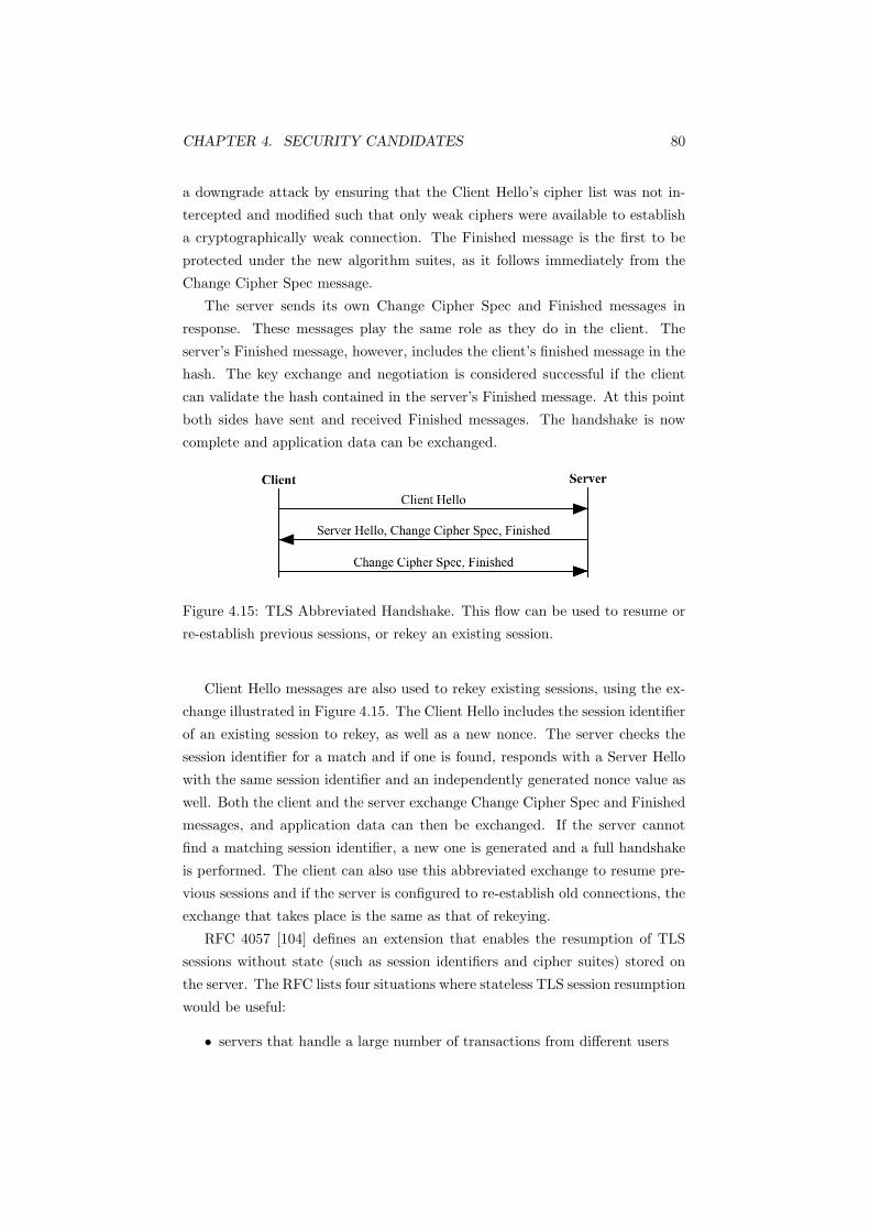
CHAPTER 4. SECURITY CANDIDATES 80
a downgrade attack by ensuring that the Client Hello’s cipher list was not in-
tercepted and modified such that only weak ciphers were available to establish
a cryptographically weak connection. The Finished message is the first to be
protected under the new algorithm suites, as it follows immediately from the
Change Cipher Spec message.
The server sends its own Change Cipher Spec and Finished messages in
response. These messages play the same role as they do in the client. The
server’s Finished message, however, includes the client’s finished message in the
hash. The key exchange and negotiation is considered successful if the client
can validate the hash contained in the server’s Finished message. At this point
both sides have sent and received Finished messages. The handshake is now
complete and application data can be exchanged.
Figure 4.15: TLS Abbreviated Handshake. This flow can be used to resume or
re-establish previous sessions, or rekey an existing session.
Client Hello messages are also used to rekey existing sessions, using the ex-
change illustrated in Figure 4.15. The Client Hello includes the session identifier
of an existing session to rekey, as well as a new nonce. The server checks the
session identifier for a match and if one is found, responds with a Server Hello
with the same session identifier and an independently generated nonce value as
well. Both the client and the server exchange Change Cipher Spec and Finished
messages, and application data can then be exchanged. If the server cannot
find a matching session identifier, a new one is generated and a full handshake
is performed. The client can also use this abbreviated exchange to resume pre-
vious sessions and if the server is configured to re-establish old connections, the
exchange that takes place is the same as that of rekeying.
RFC 4057 [104] defines an extension that enables the resumption of TLS
sessions without state (such as session identifiers and cipher suites) stored on
the server. The RFC lists four situations where stateless TLS session resumption
would be useful:
• servers that handle a large number of transactions from different users

CHAPTER 4. SECURITY CANDIDATES 81
• servers that desire to cache sessions for a long time
• ability to load balance requests across servers
• embedded servers with little memory
The first three are applicable to this project; when a server must handle a
large number of sessions from different clients, a lot of state is required which
manifests itself through larger memory usage. This can lead to reduced perfor-
mance. Sessions may be cached to avoid performing a full handshake each time
a connection is established; this improves performance. Finally load balancing
contributes to higher network availability and reliability.
Figure 4.16: TLS Handshake with the SessionTicket extension. The NewSes-
sionTicket message contains a ticket which stores the session state. This ticket
is cached by the client, relieving the server of storing session state.
If this mechanism is supported by both the client and the server (by including
an empty SessionTicket extension), the initial handshake includes a New Session
Ticket message as indicated in Figure 4.16. The New Session Ticket message
contains a ticket and is sent before the server’s Change Cipher Spec message,
after the client’s Finished message is verified. A ticket is generated by the
server and contains the session state (such as cipher suite and master secret).
It is encrypted and integrity protected using a secret key known only by the
server.
The client caches the ticket with other session parameters. When the client
resumes the session, it includes the ticket in the SessionTicket extension in the
Client Hello message (Figure 4.17). The server decrypts the ticket and verifies its
validity. The server then resumes the session based on the state and parameters
retrieved from the ticket. The server may also renew the ticket by including a
NewSessionTicket message after the ServerHello. If the server chooses not to,

CHAPTER 4. SECURITY CANDIDATES 82
the “empty SessionTicket extension” and NewSessionTicket messages are not
included in Figure 4.17.
Figure 4.17: TLS Stateless Abbreviated Handshake. In this instance the server
renews the session ticket.
If the ticket cannot be validated, the server performs a full handshake, and
may issue a new ticket (Figure 4.16) except the “empty SessionTicket extension”
message in the Client Hello contains the invalid ticket.
4.3.2 Connection Closing
The Alert protocol is used for describing various alerts, from handshake failure
to illegal parameters, as well as the severity. Connections are closed using a
close-notify message, carried using the Alert protocol. TLS uses the close-notify
message to explicitly end a session and to avoid a truncation attack. SSLv2
closed the TCP connection to end the SSL session [2]. A truncation attack is
possible in SSLv2, as attackers could forge TCP FINs to the recipient. The SSL
connection would close as the recipient has no way of determining whether the
TCP FIN was legitimate or not.
Either end of the connection can send a close-notify message. Once all
pending data is transmitted, the close-notify message is sent, and the sender
can close the write side of the connection. The receiver responds with a close-
notify and closes the connection. The initiator of the close is not required to
receive the responder’s close-notify before closing the read side of the connection.
4.3.3 Implementations and Development
TLS is supported in all current web browsers, and has made e-commerce possi-
ble. TLS has been well tested and an inductive analysis of TLS concluded that
it is a well designed protocol that meets its security goals [91]. TLS’s maturity
and its lack of known security weaknesses have made a widely used protocol.

CHAPTER 4. SECURITY CANDIDATES 83
The IETF’s tls working group12 was established in 1996 to standardise a
transport layer security protocol. From SSLv3, the group published TLS [47].
The first revision of the TLS standard was in April 2006, updating TLS to
TLS 1.1 [48]. The changes are small security improvements and clarifications.
The tls working group plan to publish a TLS 1.2 revision, which removes TLS’s
dependency on the MD-5 and SHA-1 digest algorithms, includes new encryption
modes and defines new cipher suites.
The following SSL-VPN and OpenVPN sections describe security architec-
tures based on TLS.
SSL-VPN
An emerging trend offered by VPN vendors is the ‘SSL-VPN’. A VPN securely
connects entire networks together over a public, unsecured network. It enables
traffic from any application, protocol or port to be transferred as if it was on the
same private LAN. However, most ‘SSL-VPN’ products do not meet the above
definition of a VPN at all.
Most products that claim to be an ‘SSL-VPN’ are marketed by the vendors
as a clientless VPN solution. Vendors promote enabling employee access to the
VPN via unknown clients, for example public airport or library kiosks [50], as
the main benefit of an ‘SSL-VPN’. There are several problems with this.
A popular understanding among IT publications [41, 50, 94] of the difference
between IPsec and ‘SSL-VPNs’ is that IPsec a provides a secure layer 3 pipe to
connect networks together or an extension of the network; the remote network
can be treated as if it were on the same LAN. ‘SSL-VPNs’ are understood to
provide secure access to a selected group of applications and services within the
private LAN. Use of the term ‘VPN’ in this instance is incorrect, as a VPN
provides secure tunnelling for any application.
Products declaring themselves as an ‘SSL-VPN’ fall under one of four cate-
gories: proxying, application translation, port forwarding or network extension
[67]. Proxying is when an intermediary (such as an application layer gateway,
ALG) is positioned between an internal and external application. The proxy is
seen as the end point for both sides of the connection; it accepts client requests,
rewrites them and forwards them to the server. Responses are returned the same
way. The ALG can inspect the packet and examine the data to ensure it is well
formed before forwarding the traffic. This additional processing by the proxy
reduces the performance. The proxy does not support arbitrary protocols; each
protocol supported requires separate coding.12http://www.ietf.org/html.charters/tls-charter.html (Accessed October 2006)
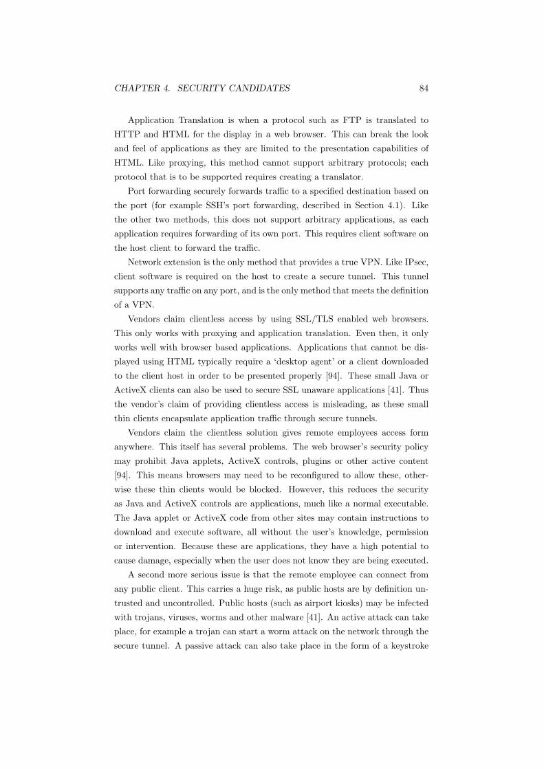
CHAPTER 4. SECURITY CANDIDATES 84
Application Translation is when a protocol such as FTP is translated to
HTTP and HTML for the display in a web browser. This can break the look
and feel of applications as they are limited to the presentation capabilities of
HTML. Like proxying, this method cannot support arbitrary protocols; each
protocol that is to be supported requires creating a translator.
Port forwarding securely forwards traffic to a specified destination based on
the port (for example SSH’s port forwarding, described in Section 4.1). Like
the other two methods, this does not support arbitrary applications, as each
application requires forwarding of its own port. This requires client software on
the host client to forward the traffic.
Network extension is the only method that provides a true VPN. Like IPsec,
client software is required on the host to create a secure tunnel. This tunnel
supports any traffic on any port, and is the only method that meets the definition
of a VPN.
Vendors claim clientless access by using SSL/TLS enabled web browsers.
This only works with proxying and application translation. Even then, it only
works well with browser based applications. Applications that cannot be dis-
played using HTML typically require a ‘desktop agent’ or a client downloaded
to the client host in order to be presented properly [94]. These small Java or
ActiveX clients can also be used to secure SSL unaware applications [41]. Thus
the vendor’s claim of providing clientless access is misleading, as these small
thin clients encapsulate application traffic through secure tunnels.
Vendors claim the clientless solution gives remote employees access form
anywhere. This itself has several problems. The web browser’s security policy
may prohibit Java applets, ActiveX controls, plugins or other active content
[94]. This means browsers may need to be reconfigured to allow these, other-
wise these thin clients would be blocked. However, this reduces the security
as Java and ActiveX controls are applications, much like a normal executable.
The Java applet or ActiveX code from other sites may contain instructions to
download and execute software, all without the user’s knowledge, permission
or intervention. Because these are applications, they have a high potential to
cause damage, especially when the user does not know they are being executed.
A second more serious issue is that the remote employee can connect from
any public client. This carries a huge risk, as public hosts are by definition un-
trusted and uncontrolled. Public hosts (such as airport kiosks) may be infected
with trojans, viruses, worms and other malware [41]. An active attack can take
place, for example a trojan can start a worm attack on the network through the
secure tunnel. A passive attack can also take place in the form of a keystroke

CHAPTER 4. SECURITY CANDIDATES 85
logger; when the remote employees authenticate themselves to the network with
a username and password, the keystroke logger would have recorded this, nulli-
fying the credentials. Networks are only as secure as the devices connected to
it.
Another problem with using public uncontrolled hosts is that session state
is left behind after the session has ended such as cached credentials, browser
history, cookies and temporary files. Many SSL-VPN solutions address this by
using applets to delete this state [94]. These applets also mitigate risk by check-
ing the capabilities of the public host, for example ensuring antivirus protection
is present. The applets can also use access rules to restrict permissions and
limit the functions available when the VPN is accessed from a public host, for
example restricting uploads. However, administrative access to the machine is
required to carry out these tasks [67]. If administrative permissions are avail-
able on a public machine, it is likely to already contain keystroke loggers, remote
control software and other malware.
Finally the ‘SSL-VPN’ solutions are proprietary. Section 2.6 discusses why
proprietary protocols are rarely better than public open standards. An ap-
plication or applet developed for one ‘SSL-VPN’ product, such as Juniper’s
Netscreen, is unlikely to work on another, such as AEP Networks’ Netilla Secu-
rity Platform, without modification.
OpenVPN
OpenVPN13 is an implementation providing a true VPN via network exten-
sion using TLS. OpenVPN uses the OpenSSL toolkit14 for cryptography. Both
projects are open source.
OpenSSL implements SSLv2/3 and TLS 1 as well as a general purpose cryp-
tography library. The TLS mode of OpenSSL was certified by the National
Institute of Standards and Technology (NIST) as FIPS 140-2 compliant in Jan-
uary 2006 [70]. The Federal Information Processing Standard (FIPS) 140-2 de-
fines security requirements for cryptographic modules. OpenSSL met the Level
1 requirements under the Cryptographic Module Validation Program (CMVP).
U.S. Government agencies and regulated industries (such as finance and health
care) are required to use FIPS compliant products to store, collect and transfer
data that is ‘sensitive but unclassified’ [13]. In July 2006, however, the certifi-
cate (#642) was revoked [69]. It is still available from the Computer Security
13http://openvpn.net14http://www.openssl.org

CHAPTER 4. SECURITY CANDIDATES 86
Resource Centre (CSRC) Validated Modules page.15
Figure 4.18: OpenVPN and a ‘TUN’ device. Applications see the virtual ‘TUN’
device as a network interface. Traffic sent to the virtual ‘TUN’ device is for-
warded to the OpnVPN service. OpenVPN then encrypts the traffic before
sending it out the network interface.
OpenVPN uses virtual networking interfaces to create encrypted tunnels. A
‘TUN’16 device is a virtual network adapter that appears as a point-to-point
device to the operating system [7, 127]. Data sent to an ethernet device is
sent out the wire by the ethernet driver, whereas data sent to a TUN device
is sent to user space applications. Applications can open the TUN device like
a folder or socket, and can read from and write IP packets to it. A ‘TAP’17
device is also a virtual adapter, but simulates an ethernet device. Figure 4.18
illustrates how a TUN device is used with OpenVPN. Data is sent to the TUN
device, which is forwarded to OpenVPN. OpenVPN uses the OpenSSL library
to encrypt the data, and then sends it out the real network device. Decryption
is the opposite; OpenVPN reads data from the real network device and decrypts
it before sending it back to the TUN device. The application then reads the
data from the TUN device.
OpenVPN encapsulates the IP data into a UDP datagram before sending it
out the real network interface. When TCP data in an IP packet is encapsulated
back into TCP (Figure 4.19), the traffic reliability mechanisms provided by
TCP are duplicated, for example retransmissions and acknowledgements. This
reduces efficiency, as the lower TCP layer guarantees delivery, so the higher
TCP layer does not need retransmissions. TCP’s retransmission algorithm uses
adaptive timeouts; when an ACK is not received after the timeout period, the
sender retransmits the packet and increases the timeout. This behaviour lets
TCP operate on connections with varying bandwidth, latency and packet loss15http://csrc.nist.gov/cryptval/140-1/1401val2006.htm16TUN does not appear to be an abbreviation, but is accepted to mean a virtual point-to-
point network device.17Like TUN, TAP also does not appear to be an abbreviation, but refers to a virtual ethernet
network device.
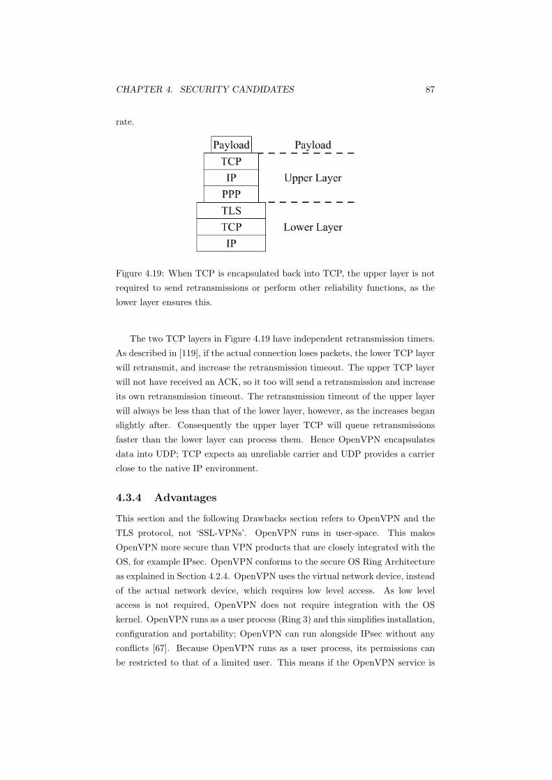
CHAPTER 4. SECURITY CANDIDATES 87
rate.
Figure 4.19: When TCP is encapsulated back into TCP, the upper layer is not
required to send retransmissions or perform other reliability functions, as the
lower layer ensures this.
The two TCP layers in Figure 4.19 have independent retransmission timers.
As described in [119], if the actual connection loses packets, the lower TCP layer
will retransmit, and increase the retransmission timeout. The upper TCP layer
will not have received an ACK, so it too will send a retransmission and increase
its own retransmission timeout. The retransmission timeout of the upper layer
will always be less than that of the lower layer, however, as the increases began
slightly after. Consequently the upper layer TCP will queue retransmissions
faster than the lower layer can process them. Hence OpenVPN encapsulates
data into UDP; TCP expects an unreliable carrier and UDP provides a carrier
close to the native IP environment.
4.3.4 Advantages
This section and the following Drawbacks section refers to OpenVPN and the
TLS protocol, not ‘SSL-VPNs’. OpenVPN runs in user-space. This makes
OpenVPN more secure than VPN products that are closely integrated with the
OS, for example IPsec. OpenVPN conforms to the secure OS Ring Architecture
as explained in Section 4.2.4. OpenVPN uses the virtual network device, instead
of the actual network device, which requires low level access. As low level
access is not required, OpenVPN does not require integration with the OS
kernel. OpenVPN runs as a user process (Ring 3) and this simplifies installation,
configuration and portability; OpenVPN can run alongside IPsec without any
conflicts [67]. Because OpenVPN runs as a user process, its permissions can
be restricted to that of a limited user. This means if the OpenVPN service is

CHAPTER 4. SECURITY CANDIDATES 88
compromised, the attacker will only be able to perform the same actions as a
limited user. Another benefit of running as a limited user (opposed to an OS
kernel process) is that OpenVPN can be ‘constrained’ to a specified directory.
This ‘containment’ denies OpenVPN access to the rest of the system. This
layering of protection (defence in depth) protects the system if OpenVPN is
compromised, as the attacker’s potential to damage the system will be extremely
limited.
OpenVPN encapsulates IP packets into UDP datagrams. Overall, UDP
based VPNs add less overhead, have better bandwidth utilisation and have a
lower latency than TCP based VPNs [76]. OpenVPN can also be configured for
load balancing using IPtables. Rules can be created to share the traffic between
a range of addresses, transparently to the applications [67].
As OpenVPN provides a secure VPN tunnel similar to IPsec, applications
can be secured without modification. This is because the TUN virtual device
appears and functions as a normal network adapter. The OpenVPN architecture
is analogous to a Bump-in-the-Stack (BITS) or a Bump-in-the-Wire (BITW)
IPsec implementation, and therefore offers similar functionality.
TLS can perform user authentication as TLS operates at a higher layer
than IPsec. Servers can authenticate users by requesting a certificate, however
this is rarely used in e-commerce sites as no Public Key Infrastructure (PKI)
exists to validate users (PKI is currently used to only authenticate servers in an
e-commerce environment). TLS, however, cannot perform user authorisation,
and relies on the upper layers.
End-to-end security is possible with TLS, as TLS encrypts at the applica-
tion layer. Applications that are natively TLS enabled benefit from end-to-end
security as data is only decrypted when it reaches the receiving application.
However, when OpenVPN is used, the connection is no longer strictly end-to-
end. Encrypted data passes through the network interface to OpenVPN, which
decrypts it, and forwards it to the virtual TUN device. Any application listen-
ing on the TUN device (for example ethereal or wireshark) will see the data in
plaintext. Applications listening on the actual network interface, however, will
still see the ciphertext as OpenVPN has not decrypted it yet.
TLS connections can successfully traverse NAT devices. NAT devices typ-
ically change source addresses and ports. TLS is not affected, as the MAC is
calculated over the data, the MAC key and a sequence number; the MAC does
not include the address and ports.
TLS is also application independent as higher layer protocols can be layered
on top (for example HTTPS for HTTP and SIPS for SIP URIs). OpenVPN

CHAPTER 4. SECURITY CANDIDATES 89
extends this so that applications do not need to be aware they are using an
encrypted tunnel. TLS’s only requirement is that it operates over a reliable
transport protocol.
Finally hardware accelerated SSL/TLS devices exist to offload the computa-
tionally expensive cryptographic functions from the main CPU. OpenSSL can
be accelerated with these devices, and OpenVPN can benefit as well as it uses
OpenSSL for its cryptography functions.
4.3.5 Drawbacks
As TLS operates at a relatively high level, the packet drop performance will be
lower than security protocols that operate at lower layers (for example IPsec).
Packets are processed by more layers in the network stack before they are dis-
carded. However, hardware accelerators can be used to improve overall TLS
performance.
Another drawback is client authentication. As no PKI exists for clients,
e-commerce websites only authenticate the server with certificates, and authen-
ticate the user with a username and password. In a VPN this is less of a problem,
however, as users can obtain certificates from their own corporate CA. For the
purposes of this project, this is not a problem as the remote devices (instead
of users) would preloaded with certificates distributed by the corporate CA (for
example the trusted manufacturer of the transaction terminal).
4.3.6 Summary
TLS is based on SSLv3. It is widely deployed and developed and is the standard
way to secure e-commerce transactions over the internet.
This section described three systems: ‘SSL-VPNs’, OpenVPN and TLS/Open-
SSL. ‘SSL-VPNs’ are generally products that use the term VPN incorrectly.
These products are usually nothing more than proxies or application transla-
tors and fall far short of the definition of a VPN. The advantage ‘SSL-VPNs’
have over other VPN products is that no client software is required. However,
when port forwarding or network extension is the method used, clients are re-
quired. ‘SSL-VPNs’ have flaws in their security model and are also proprietary.
OpenVPN is an open source VPN product that offers application/port in-
dependent tunnelling functionality similar to IPsec. However, OpenVPN runs
in user space. Running in user space gives OpenVPN several advantages over
IPsec, such as ease of installation and configuration as well as being able to
contain the damage by an attacker if compromised. OpenVPN uses OpenSSL,

CHAPTER 4. SECURITY CANDIDATES 90
an open source cryptographic library that implements TLS.
TLS is capable of authenticating users via certificates however this is rarely
used in e-commerce due to a lack of an appropriate PKI. While TLS may have
lower performance than other systems due to operating at a higher layer, per-
formance can be accelerated with specialised hardware.
TLS is still under active development. These continued improvements will
ensure the security of e-commerce. TLS’s advantages and lack of drawbacks
make it candidate tunnelling method.
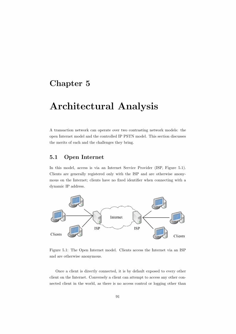
Chapter 5
Architectural Analysis
A transaction network can operate over two contrasting network models: the
open Internet model and the controlled IP PSTN model. This section discusses
the merits of each and the challenges they bring.
5.1 Open Internet
In this model, access is via an Internet Service Provider (ISP, Figure 5.1).
Clients are generally registered only with the ISP and are otherwise anony-
mous on the Internet; clients have no fixed identifier when connecting with a
dynamic IP address.
Figure 5.1: The Open Internet model. Clients access the Internet via an ISP
and are otherwise anonymous.
Once a client is directly connected, it is by default exposed to every other
client on the Internet. Conversely a client can attempt to access any other con-
nected client in the world, as there is no access control or logging other than
91

CHAPTER 5. ARCHITECTURAL ANALYSIS 92
those performed by the ISP for billing purposes. This unregulated environ-
ment brings risk as all types of network attacks are possible, such as intrusion,
information theft and DoS attacks.
Firewalls can be implemented at the endpoints to reduce these risks and NAT
is often used to conceal internal network infrastructure information. NAT, how-
ever, often causes connectivity problems in applications when the application
inserts private non-routable addresses in the packet payload. NAT devices also
remove the end to end significance of the IP addresses of the hosts on the two
ends of the connection. This poses a problem for communications that rely
on peer to peer connections such as VoIP and file sharing applications. Hosts
behind a NAT device cannot receive unsolicited incoming connections; hosts
behind a NAT must initiate the connection. Several solutions exist to work
around this, such as Universal Plug and Play (UPnP) and Simple Traversal
of UDP through NATs (STUN). However, these solutions are not scalable or
widely implemented [18].
5.1.1 Advantages
The advantage of an open peer to peer model is not having a single point
of failure; for example, in peer to peer file sharing networks, nodes are both
clients and servers. However, a transaction network does not benefit from this
advantage as it uses a client-server model as noted in Section 2.6.
The Internet is also generally fault tolerant and when paired with a presence
architecture (for example SIMPLE, used in IM applications), real time knowl-
edge of the status of network components is possible. This can contribute to
network availability as clients will know which servers are available, and vice
versa if required (transaction servers typically do not need to know the status
of transaction clients).
5.1.2 Drawbacks
There are several drawbacks to operating a transaction network over the Inter-
net. A major disadvantage is the lack of security; in an uncontrolled environ-
ment, data can be monitored as it passes through intermediaries. Encryption
and data integrity protection largely protect from this risk however.
As every directly connected device is exposed to every other device, DoS at-
tacks on transaction processing servers are possible. Attackers are anonymous
and untraceable as source IP addresses can be spoofed. Network infrastructure
can be protected from DoS attacks by using class based queuing and real time

CHAPTER 5. ARCHITECTURAL ANALYSIS 93
traffic monitoring as detailed in [73]. Such measures can also contribute to scal-
ability; a load balancer placed between the transaction servers and the Internet
can tunnel transactions to the transaction processors with the least number of
connections. The load balancer can also use the class based queuing mechanism
to throttle transactions during congestion or peak load situations.
The Internet model also lacks QoS guarantees; it is typically a best effort
service. A transaction network requires a low latency, reliable network. These
parameters cannot be guaranteed in the open Internet model.
As the Internet is uncontrolled, real time network management functions
are limited to the server’s side; successful transactions can be measured on the
server only. Unsuccessful transactions, however, cannot be measured in real
time without co-operation with the client’s ISP. Statistics on failed transactions
initiated by the client can however still be reported ‘offline’, for example at
the end of each hour or day.1 However, other management functions such as
knowing which transaction servers are congested or offline are still available, by
using a presence architecture such as SIMPLE.
5.2 Controlled IP PSTN
The term “IP PSTN” refers to a private IP network desgined for VoIP, rather
than a public switched telephone network. In this model, access is via an IP
PSTN provider (Figure 5.2). Clients reside on their own subnet and access the
private network through the provider’s Session Border Controller (SBC). SBCs
are also known as back-to-back user agents (B2BUA) and are essentially an
application layer gateway and proxy and are situated between the participants
of a session. They control access to the private network and this gives the
provider complete control over policies for admission to the service.
Each client has a common identifier (a SIP URI) and must register with a
SIP registrar before accessing the network. This assists in NAT traversal, as
the SBC becomes the source and destination for all signalling messages and
media streams entering and leaving the provider’s network [15]. SBCs can be
considered an implementation of the mechanism defined in [100].
When a client registers with a SIP registrar/call agent (Figure 3.22), the
SBC maps the source IP address and port of the REGISTER message to the
client’s SIP URI. The IP address and port mapped however do not actually
belong to the client; they belong to the client’s firewall/NAT device. The SBC
1Offline here means “not in real time” (that is, not reporting failure as it occurs), rather
than being disconnected from the Internet.

CHAPTER 5. ARCHITECTURAL ANALYSIS 94
Figure 5.2: The Controlled IP PSTN model. Clients (which may be IP tele-
phones) connect to the IP PSTN Core network via Session Border Controllers
(SBC), which are under the control of the service provider.
modifies the REGISTER message so the CONTACT and VIA fields point to
the SBC [18]. The SIP registrar then binds the client (via the SIP URI) to the
SBC’s address.
When the call agent is queried on the location of the client (Figure 3.20), the
SBC’s address is returned. Hence signalling messages addressed to the client
are directed to the SBC. When the SBC receives a signalling message addressed
to the client (for example an INVITE), it is forwarded to the IP address and
port associated with that client’s URI.
When the client initiates a call, the INVITE request is sent to the SBC. The
SBC replaces any relevant fields in the INVITE request such that it appears
to originate from the SBC. The modified INVITE is then forwarded to the call
agent. The response will go back to the SBC, which will forward it to the client
behind the firewall/NAT device. This makes the SBC the source and destination
for all sessions.
Media streams are also proxied through the SBC. The SBC knows which IP
and port the firewall/NAT device allocated for the client’s outgoing media. This
IP address and port is associated with the client’s URI. The SBC then forwards
incoming media addressed to the client’s URI to the same IP address and port.
By performing application layer gateway functionality (by modifying the fields
in SIP messages) and proxying (by making itself the source and destination of all
messages), SBC’s can successfully traverse NAT devices without modifications
to existing hardware, software, firewall configurations or security policies.

CHAPTER 5. ARCHITECTURAL ANALYSIS 95
5.2.1 Advantages
There are other benefits to having a provider controlled SBC situated in the
signalling and media path. SBCs have the topology hiding security benefits of
NAT, as the SBC conceals the details of the client’s internal network topology.
Clients receiving session invites will always see the SBC as the source, not the
originating network or client. Outgoing calls are proxied through the SBC,
which replaces the real source address with its own.
Clients can only access other clients permitted by the SBC, unlike the In-
ternet model, where any other client is accessible by any other. As clients must
initiate sessions through the SBC, the SBC can deny any session invite via policy
if required. The SBC can also completely deny access to unauthorised clients.
SBCs enable service providers to provide a VoIP service, while replicating the
traditional phone networks. Service providers can retain their existing business
models in a VoIP network as they have full control over the network.
The SBC can also protect network and service infrastructure from attack.
As the client’s real address is not exposed, it is protected from port scans and
DoS attacks. Conversely a client cannot initiate port scans or DoS attacks on
other clients, as the SBC will not allow the traffic onto the core network.
SBCs also enable the service provider to manage and control sessions. This
can be in the form of logging failed transactions in real time for example. As all
traffic must pass through the SBC, it can also throttle traffic if it is abnormally
excessive (for example during a DoS attack). This may also happen during peak
load scenarios; the throttling mechanism enables clean failure. Transaction
processors will gracefully reject new requests, but continue to service current
requests. This highly regulated private network environment also makes QoS
possible; SBC’s can provide a link with a guaranteed level of service (for example
minimum latency).
5.2.2 Disadvantages
Operating a transaction network over an IP PSTN also has disadvantages. The
SBC, with all the benefits it brings to an IP PSTN is also the source of all
the drawbacks in this model. The SBC represents a single point of failure, as
all connections and sessions run through it. Having multiple redundant SBCs
reduces this risk.
As all connections access the IP PSTN through the SBC, it can become a
bottleneck, limiting performance and security. The SBC breaks the end to end
transparency as it acts as the called client, then places a second call to the actual

CHAPTER 5. ARCHITECTURAL ANALYSIS 96
destination. This can introduce latency. Ensuring sufficient SBCs are deployed
to handle peak, not average load scenarios can reduce these drawbacks.
The capabilities of clients are also limited to the capabilities of the SBC,
as the SBC functions as a proxy. This may not be a problem in a regulated
transaction network, as all clients will be uniform in capability and specification.
Control of the session is mediated by the SBC. This is a drawback if the
clients do not trust the service provider. End to end encryption cannot be used,
as SBCs need to be able to modify packet contents. Encryption of the payload,
however, is possible as long as the headers the SBC modifies is in plaintext, or
the SBC has the ability to decrypt the headers.
5.3 Conclusion
The open Internet model offers clients relatively anonymous and unregulated
access to every other client connected. Clients are also exposed to every other
connected client. This brings security risks. Firewalls can be used to reduce the
risk, however this introduces NAT traversal issues. While solutions exist, they
are not scalable or widely implemented. Even if an elegant solution to NAT
traversal was developed, the Internet model lacks QoS abilities, a requirement
for a transaction network.
The IP PSTN however offers a highly regulated QoS enabled service. The
high level of control wielded by the service provider (via the SBCs) ensures
security, as clients can only access other clients allowed by the SBC. As the
SBC’s separate the clients by acting as a proxy, no network topology information
is revealed. This protects against DoS attacks. SBCs can also throttle traffic, as
they are QoS enabled. This also protects against DoS attacks, but also enables
the network to function during peak load scenarios; the transaction processing
rate will drop, but not fail completely.
Some disadvantages of running a transaction network over an IP PSTN can
be overcome by ensuring enough SBCs are deployed, such that they do not
become a potential bottleneck or present a single point of failure. Security
also relies on the clients trusting the service provider and SBCs. Table 5.1
summarises the difference between the two models.
Overall the advantages of an IP PSTN over the Internet make it the prefer-
able network architecture on which to operate a transaction network.

CHAPTER 5. ARCHITECTURAL ANALYSIS 97
Property Open Internet IP PSTN
Access Public via ISP Controlled via SBC
Connection Direct connection Proxied via SBC
Client Anonymous? Yes No
Client Accessible to Others? Yes No unless permitted by SBC
Client can Access Others? Yes No unless permitted by SBC
QoS Possible? No Yes
Network Management Functions? Partial Yes
End to End transparency? Yes No
NAT Traversal? Needs additional server Yes
Table 5.1: Summary of differences between the open Internet model and an IP
PSTN
5.4 Architectural Options
This section describes architectures built on the two different models, and how
they would meet the requirements.
5.4.1 IP PSTN Solution
A solution based on the IP PSTN could be arranged as in Figure 5.3. Clients
access the core network via an SBC. The SBC forwards the transaction from
the client to the receiver’s SBC (SBC2). The receiver in this case is a trans-
action processor. There may be a concentrator physically placed between the
transaction processor and the SBC as illustrated, however the concentrator and
transaction processor can be logically considered a single component. A concen-
trator combines transactions from many connections into a single connection.
The concentrator also operates as a firewall, protecting the transaction pro-
cessor from harmful traffic. Multiple transaction processors may be positioned
behind the concentrator for load balancing, for example, the concentrator may
allocate transactions on a round robin basis.
SIP would be required to access the core network via the SBC. The SIMPLE
extensions could also be used, giving the network a degree of service awareness
(for example notification of which servers are unavailable, offline or congested,
described in Section 3.6.4).
A total VPN solution providing transparent network access (using the remote
network as if it were a local network) is not required in this situation; clients
send transactions to the transaction processor and receive acknowledgements.
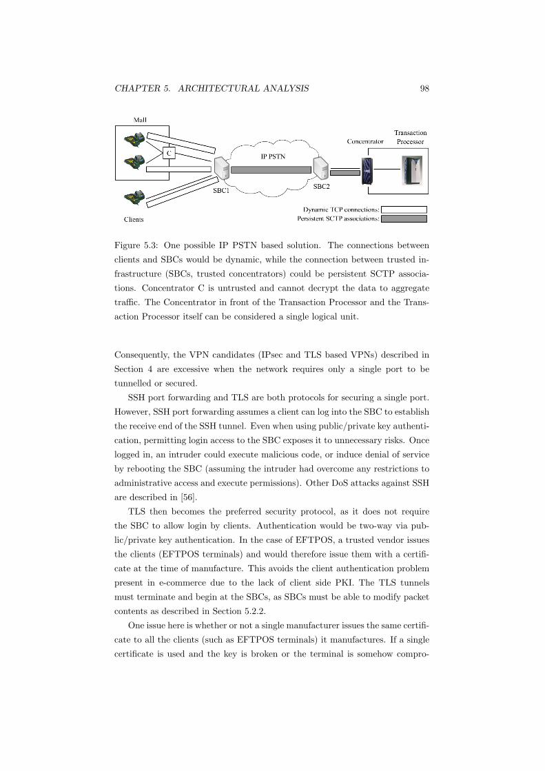
CHAPTER 5. ARCHITECTURAL ANALYSIS 98
Figure 5.3: One possible IP PSTN based solution. The connections between
clients and SBCs would be dynamic, while the connection between trusted in-
frastructure (SBCs, trusted concentrators) could be persistent SCTP associa-
tions. Concentrator C is untrusted and cannot decrypt the data to aggregate
traffic. The Concentrator in front of the Transaction Processor and the Trans-
action Processor itself can be considered a single logical unit.
Consequently, the VPN candidates (IPsec and TLS based VPNs) described in
Section 4 are excessive when the network requires only a single port to be
tunnelled or secured.
SSH port forwarding and TLS are both protocols for securing a single port.
However, SSH port forwarding assumes a client can log into the SBC to establish
the receive end of the SSH tunnel. Even when using public/private key authenti-
cation, permitting login access to the SBC exposes it to unnecessary risks. Once
logged in, an intruder could execute malicious code, or induce denial of service
by rebooting the SBC (assuming the intruder had overcome any restrictions to
administrative access and execute permissions). Other DoS attacks against SSH
are described in [56].
TLS then becomes the preferred security protocol, as it does not require
the SBC to allow login by clients. Authentication would be two-way via pub-
lic/private key authentication. In the case of EFTPOS, a trusted vendor issues
the clients (EFTPOS terminals) and would therefore issue them with a certifi-
cate at the time of manufacture. This avoids the client authentication problem
present in e-commerce due to the lack of client side PKI. The TLS tunnels
must terminate and begin at the SBCs, as SBCs must be able to modify packet
contents as described in Section 5.2.2.
One issue here is whether or not a single manufacturer issues the same certifi-
cate to all the clients (such as EFTPOS terminals) it manufactures. If a single
certificate is used and the key is broken or the terminal is somehow compro-

CHAPTER 5. ARCHITECTURAL ANALYSIS 99
mised, the entire system would also be compromised. Global secrets are a bad
design feature, and once compromised, are difficult to recover from [107]. The
contrary requires the manufacturer to install different certificates/keys/secrets
in each terminal.
This raises another related issue of whether the terminals can be modified or
upgraded. If they can be upgraded, then in the event of key compromise, they
can be installed with a new secret key. However, this also enables tampering of
the terminals; it could be possible for malicious third parties to upload their own
certificate or secret into the terminal. Conversely, if the terminals were made
tamperproof and not upgradeable, it would not be possible for malicious parties
to read the contents of its secret, nor install their own keys. Obviously, in this
situation, manufacturers would not be able to upgrade or install new secrets.
One solution could be to have terminals that are upgradeable, but unreadable.
The terminals would have to be tamperproof to avoid malicious interference.
While these last two client terminal issues (global secrets and upgradeability)
are important, they stray beyond the scope of this project.
The connection could operate over either TCP or SCTP. While TCP is
stream based, SIP’s SIMPLE (more specifically the MESSAGE function) pro-
vides the application layer framing to distinguish between separate messages.
Both are reliable transport protocols with flow control mechanisms.
When a client requires access to the core network, it must register with the
SBC (as described in Section 5.2) to support NAT traversal. This would involve
the following steps:
1. TCP/SCTP establishment
2. TLS establishment
3. SIP REGISTER
4. SIP SUBSCRIBE (optional; this would let the client know the status of
the transaction processors)
5. TLS close notify
6. TCP/SCTP close
After a client has registered with the SBC, it may send transactions. One
issue is whether clients should use a single secured SIP session for every trans-
action, or establish and close a secured SIP session each time a transaction is
sent (Figure 5.4).
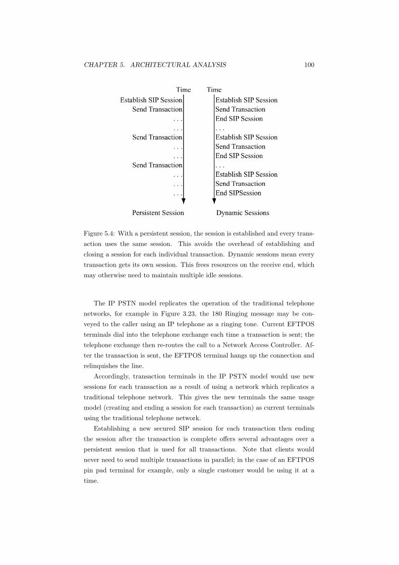
CHAPTER 5. ARCHITECTURAL ANALYSIS 100
Figure 5.4: With a persistent session, the session is established and every trans-
action uses the same session. This avoids the overhead of establishing and
closing a session for each individual transaction. Dynamic sessions mean every
transaction gets its own session. This frees resources on the receive end, which
may otherwise need to maintain multiple idle sessions.
The IP PSTN model replicates the operation of the traditional telephone
networks, for example in Figure 3.23, the 180 Ringing message may be con-
veyed to the caller using an IP telephone as a ringing tone. Current EFTPOS
terminals dial into the telephone exchange each time a transaction is sent; the
telephone exchange then re-routes the call to a Network Access Controller. Af-
ter the transaction is sent, the EFTPOS terminal hangs up the connection and
relinquishes the line.
Accordingly, transaction terminals in the IP PSTN model would use new
sessions for each transaction as a result of using a network which replicates a
traditional telephone network. This gives the new terminals the same usage
model (creating and ending a session for each transaction) as current terminals
using the traditional telephone network.
Establishing a new secured SIP session for each transaction then ending
the session after the transaction is complete offers several advantages over a
persistent session that is used for all transactions. Note that clients would
never need to send multiple transactions in parallel; in the case of an EFTPOS
pin pad terminal for example, only a single customer would be using it at a
time.

CHAPTER 5. ARCHITECTURAL ANALYSIS 101
A persistent transport layer connection (and therefore session) may be dropped
if no traffic is sent after a long period. Thus, when the client comes to use the
connection, it will find that the connection is down and would need to establish
a new connection regardless. With a dynamic connection, the application can
be sure that the connection exists and works when it comes to use it, as it has
just established it.
Applications that use persistent connections may use keep alives or heart-
beats to ensure the connection is not dropped. Using frequent keep alives,
however, gives passive observers more ciphertext data for traffic analysis.
Establishing a new secured connection for each transaction ensures a dif-
ferent key is used for each. With a persistent connection, a rekeying interval
needs to be specified (for example after n transactions, or perhaps even after
every transaction). This issue is avoided altogether when using a new ses-
sion/connection for each transaction. This assumes that the underlying random
number generator in the TLS implementation does not generate random num-
bers that were recently used.
The only disadvantage of using a new session/connection for each transaction
is the overhead in establishing and ending each one (see Figure 5.4). Whether
establishing a single connection is time consuming will be revealed in the testbed.
Consequently, the connection between clients and the SBC are dynamic;
they are established when needed, and closed when the transaction is finished.
When the client wishes to send a transaction (having registered with the SBC),
it would take the following steps:
1. TCP establishment
2. TLS establishment
3. SIP INVITE
4. SIP MESSAGE (to transfer the transaction data)
5. SIP BYE
6. TLS close notify
7. TCP close.
The connection does not need to be the same between SBCs, or between the
SBC and the transaction processor (Figure 5.3) as it is between clients and the
SBC. This is because the trust model is different; every node in the IP PSTN
core network is trusted (as the SBCs control access). While the connection

CHAPTER 5. ARCHITECTURAL ANALYSIS 102
characteristics (more specifically the use of dynamic TCP sessions) could be the
same, the SBCs could also use persistent SCTP associations to other SBCs.
In Figure 5.3, SBC1 aggregates three TCP sessions into a single SCTP asso-
ciation to SBC2. SBC2 could have a persistent SCTP association to the trans-
action concentrator. The concentrator terminates connections from multiple
SBCs, ensuring the transaction processor experiences no overhead from client
connects/disconnects; the processor only sees a continuous stream of transaction
messages.
Trusted concentrators can also be placed before the SBC as shown in Figure
5.5 (for example at a large shopping mall). The connection between the trusted
mall concentrator and the nearest SBC could also be a persistent SCTP con-
nection. This can contribute to scalability, resulting in the SBC viewing the
concentrator still as many parallel transactions (for example two shops at the
mall can send a transaction at once), but without the overhead of establishing
an independent connection for each. SCTP has the advantages as described in
Section 3.4, such as multistreaming and multihoming.
Figure 5.5: In this instance, C is a trusted concentrator, and can therefore
decrypt the transaction traffic. If a concentrator on the client end is warranted,
the connection between the trusted concentrator and the client’s SBC would be
a persistent SCTP association.
While encrypted keep alives can give observers more data for traffic analysis,
SBCs would not grant IP PSTN access to potential intruders/observers.
Since SBCs and transaction processors deal with many sessions at once, the
overhead in establishing and ending multiple connections may become signifi-
cant. Using a persistent SCTP association avoids this overhead. SCTP’s mul-
tistreaming may contribute to the performance (as each exchange between the
client and SBC would in effect get its own dedicated stream) and multihoming
would contribute to reliability between SBCs.

CHAPTER 5. ARCHITECTURAL ANALYSIS 103
A persistent TCP connection could also be used, which would also avoid this
overhead. It would have SCTP’s benefits of aggregating multiple sessions into a
single TCP session, although to a lesser extent, as TCP cannot replicate multiple
SCTP streams in a single connection (see the Head of Line blocking discussion in
Section 3.4). If dynamic TCP sessions were used between SBCs or between SBCs
and the transaction processor (Figure 5.6) and were not aggregated, dedicated
hardware accelerators may be required to handle the establishment and closing
of multiple TLS connections at once. To replicate the multihoming function of
SCTP, the responsibility and knowledge of using an alternative address would
be moved up from the transport layer to the application, using the presence
information provided by SIMPLE.
Figure 5.6: A solution using only dynamic TCP connections. As there is no
aggregation before the concentrator, the infrastructure must be powerful enough
to handle large numbers of TLS connections.
As stated in Section 5.2.2, end to end encryption cannot be used because
SBCs need to be able to modify the packet contents. The terminals would have
a tunnel to the SBC; the SBC would have a different tunnel to the destination
SBC and the destination SBC would have its own tunnel to the transaction
processor network. Using separate independent tunnels means if SBCs do use
persistent connections, the tunnel between the client and the client’s SBC can be
established and closed when transactions need to be sent, while the tunnels be-
tween SBCs remain persistent. This adds to reducing connection establishment
and closing overhead.
5.4.2 Open Internet Solution
While the Internet model is not the preferred solution, it is still worth analysing
how capable it could be when compared to a network based on an IP PSTN.
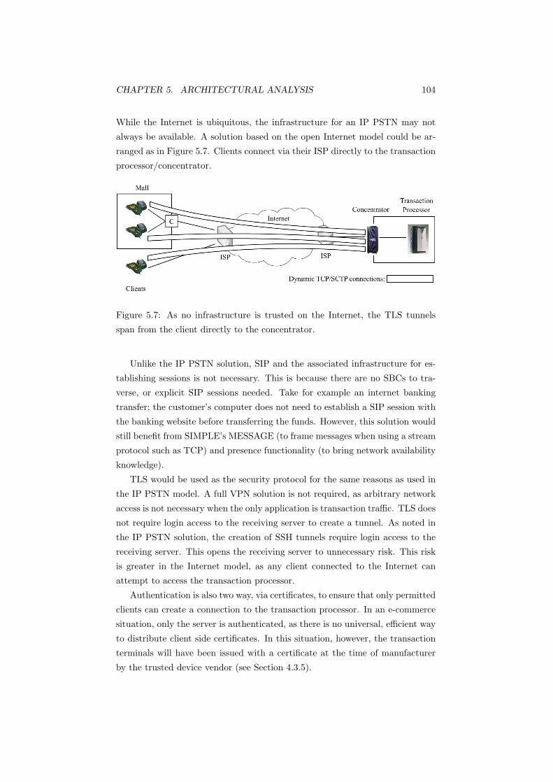
CHAPTER 5. ARCHITECTURAL ANALYSIS 104
While the Internet is ubiquitous, the infrastructure for an IP PSTN may not
always be available. A solution based on the open Internet model could be ar-
ranged as in Figure 5.7. Clients connect via their ISP directly to the transaction
processor/concentrator.
Figure 5.7: As no infrastructure is trusted on the Internet, the TLS tunnels
span from the client directly to the concentrator.
Unlike the IP PSTN solution, SIP and the associated infrastructure for es-
tablishing sessions is not necessary. This is because there are no SBCs to tra-
verse, or explicit SIP sessions needed. Take for example an internet banking
transfer; the customer’s computer does not need to establish a SIP session with
the banking website before transferring the funds. However, this solution would
still benefit from SIMPLE’s MESSAGE (to frame messages when using a stream
protocol such as TCP) and presence functionality (to bring network availability
knowledge).
TLS would be used as the security protocol for the same reasons as used in
the IP PSTN model. A full VPN solution is not required, as arbitrary network
access is not necessary when the only application is transaction traffic. TLS does
not require login access to the receiving server to create a tunnel. As noted in
the IP PSTN solution, the creation of SSH tunnels require login access to the
receiving server. This opens the receiving server to unnecessary risk. This risk
is greater in the Internet model, as any client connected to the Internet can
attempt to access the transaction processor.
Authentication is also two way, via certificates, to ensure that only permitted
clients can create a connection to the transaction processor. In an e-commerce
situation, only the server is authenticated, as there is no universal, efficient way
to distribute client side certificates. In this situation, however, the transaction
terminals will have been issued with a certificate at the time of manufacturer
by the trusted device vendor (see Section 4.3.5).

CHAPTER 5. ARCHITECTURAL ANALYSIS 105
Figure 5.7 shows the encrypted tunnels span from the client device directly
through to the transaction processor. Like the IP PSTN solution, a concentra-
tor may be physically placed between the network and the actual transaction
processor. The tunnel is not terminated in any way before it arrives at the
transaction processor, as no infrastructure connected to the Internet is trusted
(unlike the SBCs in the IP PSTN model).
Again, like the IP PSTN solution, the connection between the terminals and
the concentrator could be either TCP or SCTP. Both are reliable transport pro-
tocols with compatible flow and congestion control mechanisms. Transactions
would not be aggregated while being routed through the Internet, as no infras-
tructure would be trusted to decrypt the transactions and combine them. This
is not a major problem, however, because the devices connect directly to the
concentrator; each device can only send a single message at a time (for example
only one customer can be entering their PIN into a keypad at a time).
The concentrator would then aggregate these connections onto a single SCTP
association, directed to the transaction processor. The connection between the
concentrator and the transaction processor could also be a TCP connection as
in the IP PSTN solution. This would require SIMPLE’s MESSAGE application
layer framing in order for the transaction server to determine where each trans-
action started and ended. The concentrator would require hardware that could
handle multiple TLS tunnels at once to ensure adequate performance.
For high transaction rate sites (for example a large shopping mall), a con-
centrator can also be placed in front of the transaction server’s concentrator
(Figure 5.8). This is identical to the site concentrator in Figure 5.5. If the
transaction rate is high enough to warrant a site concentrator, then it would
use a persistent SCTP connection to the transaction processor’s concentrator.
Once more like the IP PSTN solution, the connection between the devices
and the destination (the concentrator in this case) would be dynamic. A con-
centrator would be unable to support a persistent TLS secured tunnel for every
possible transaction device on the network. The justifications for using a dy-
namic connection in the IP PSTN solution also apply in this solution. Idle
connections may be dropped after a certain period. Heartbeats or keep alives
may be used to keep connections alive, but these offer more ciphertext data for
traffic analysis. On the open Internet, where nothing is trusted, this becomes a
significant risk.
When a client wishes to send a transaction, it would take the following steps:
1. TCP establishment
2. TLS establishment

CHAPTER 5. ARCHITECTURAL ANALYSIS 106
Figure 5.8: In this instance, C is a trusted concentrator, so has the ability to
decrypt transaction traffic. It aggregates these onto a single SCTP association,
reducing the load on the transaction processor’s concentrator.
3. SIP MESSAGE (to transfer the transaction data)
4. TLS close notify
5. TCP close
Unlike the IP PSTN model, where only trusted clients could access the core
network and other clients, the Internet has no access restrictions. This opens
the Internet based solution to all forms of DoS attacks, including Distributed
DoS (DDoS) and Distributed Reflection DoS attacks (DRDoS). DoS attacks
are identified as either exploiting a network problem or an individual problem
in [90]. Network problems are based on abusing flaws in Internet protocols
and infrastructure. Individual problems focus on taking advantage of poorly
configured systems and harnessing them for use as attack zombies.
Improving the infrastructure can mitigate network problems, for example
load balancing and traffic queuing [73]. Protocols can be altered as well, for
example using SYN cookies to avoid SYN flooding (as described in Section
3.3.3). Cryptographic puzzles can be used to impose a computational cost to
clients wanting to establish a TLS connection with a server; a method to reduce
the computational load on the server when performing a TLS handshake is
described in [35]. As the TLS receive rate increases, the complexity of the
puzzle increases, giving the server a constrained means to limit the send rate of
clients.
Honeypot or Honeynet diversion networks can be deployed within the DMZ
part of the network as described in [90]. IDSs can be installed on the network,
triggering alerts when unusual network activity occurs.

CHAPTER 5. ARCHITECTURAL ANALYSIS 107
Improvements in network infrastructure and protocols alone, however, can-
not protect from DoS attacks completely; individual computers and users must
also take measures to protect against DoS attacks. Antivirus and anti-malware
software should be used to ensure computers and equipment do not become
infected and are used as launch pads for DoS attacks. Firewalls should be con-
figured for ingress/egress filtering (for example ensuring that traffic leaving the
network does not have an external source address and incoming traffic does not
have an internal source address). Operating systems and software must also be
kept up to date with the latest patches and bug fixes.
Ultimately, the problem stems from the inability to identify and separate
malicious traffic from legitimate traffic. Previous work found the best solution
was to detect the attack as early as possible, trace the IP address of the source
then notify the administrators of the zombie machines [90]. However, they
concluded there was no 100 percent effective method for defending against DoS
attacks.
5.4.3 Conclusion
A transaction network can be based on an IP PSTN or the open Internet model.
The two architectures described meet all of the qualitative requirements set out
in Section 2.6. Whether these architectures meet the quantitative requirements
(such as scalability, throughput and response time) can only be determined
after a proof of concept testbed has been created and benchmarked. Table
5.2 summarises the mapping of these solutions to the requirements set out in
Section 2.6. It is interesting to note that despite the differences in the network
models, the solution architectures are very similar. The main point of difference
is in the QoS guarantees and security. Only the IP PSTN can provide QoS
guarantees; the Internet is a best effort service. In Table 5.2, the Send Rate
Limited row alludes to DoS attacks, as DoS attacks rely on overwhelming the
server’s bandwidth or system resources. As the Internet is an uncontrolled
network, the risk of DoS attacks can never be removed, only reduced.
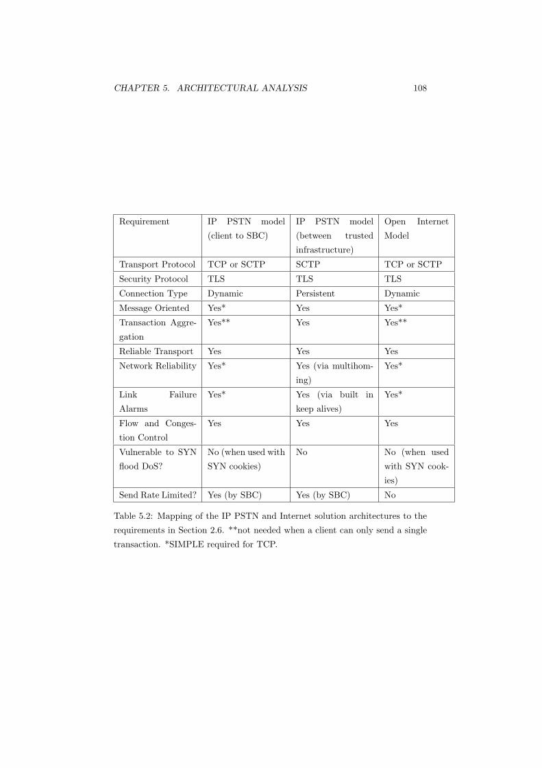
CHAPTER 5. ARCHITECTURAL ANALYSIS 108
Requirement IP PSTN model
(client to SBC)
IP PSTN model
(between trusted
infrastructure)
Open Internet
Model
Transport Protocol TCP or SCTP SCTP TCP or SCTP
Security Protocol TLS TLS TLS
Connection Type Dynamic Persistent Dynamic
Message Oriented Yes* Yes Yes*
Transaction Aggre-
gation
Yes** Yes Yes**
Reliable Transport Yes Yes Yes
Network Reliability Yes* Yes (via multihom-
ing)
Yes*
Link Failure
Alarms
Yes* Yes (via built in
keep alives)
Yes*
Flow and Conges-
tion Control
Yes Yes Yes
Vulnerable to SYN
flood DoS?
No (when used with
SYN cookies)
No No (when used
with SYN cook-
ies)
Send Rate Limited? Yes (by SBC) Yes (by SBC) No
Table 5.2: Mapping of the IP PSTN and Internet solution architectures to the
requirements in Section 2.6. **not needed when a client can only send a single
transaction. *SIMPLE required for TCP.

Chapter 6
Architectural
Implementation
This section describes the architectural validation via a proof of concept net-
work and justifies design decisions in the implementation. The network aims
to demonstrate the viability of the two architectures: IP PSTN and Internet,
described in the previous section.
Validating the architectures required the use of a live test bed network in-
stead of a simulation. This is because network simulations cannot accurately
model specific application level protocol exchanges. A network simulation also
does not demonstrate the chosen messaging and security protocols in operation.
The client, concentrator and trasaction processor were all written in Java.
The JAIN-SIP library1 was used. JAIN-SIP is an open source implementation
of RFC 3261. The client was initially written in C, using the Sofia-SIP library2,
also an open source SIP library. A native C/C++ implementation is gener-
ally faster than runtime compiled implementations (for example Java and C#).
However, Java was ultimately chosen, as the JAIN-SIP library was easier to
use. Performance differences between the languages are also insignificant when
compared to the impact imposed by encryption, digital signatures and network
latency.1https://jain-sip.dev.java.net2http://sofia-sip.sourceforge.net
109

CHAPTER 6. ARCHITECTURAL IMPLEMENTATION 110
6.1 The Client
The client software initiated sessions to send transactions. The most accurate
approach to demonstrate the network would be to utilise a large number of
physical clients, each running a single instance of the client software. This
was not feasible, however, so the client software was multithreaded, using each
thread to represent a single instance of the client. A rudimentary user interface
was created to separate transaction progress from error messages (Figure 6.1).
The ‘Start’ button initialised and ran a number of threads, specified by the
number entered in the ‘Threads’ field. From herein, ‘client’ refers to a particular
instance of a thread. Thus, clicking ‘Start’ for 200 threads approximated 200
clients. Each ‘client’ or thread ran through the exchange in Figure 6.3 or Figure
6.4 (depending on the architecture selected) in parallel with the other threads
(that is, the threads were not run sequentially one after the other). Message
payloads were 300 bytes long (as stated in [14]). Timeouts were set to 5000ms;
if the client did not receive a response to any request within 5000ms, it assumed
the server was down and tried another (in the Internet model) or retransmitted
(in the IP PSTN model). The transaction timeout was set to 5000ms as it was
considered an acceptable time to wait for a transaction to go through; transac-
tion terminal users can take this long to enter their PIN. While lower timeouts
would improve performance in the event of transaction processor failure, lower
times could also unnecessarily congest the network; the client could potentially
consider the transaction processor nonfunctional, when in reality it was simply
taking longer than usual to complete the transaction.
The network implemented here differs slightly from the architectures de-
scribed in Section 5.4. Section 5.4 described the use of SIMPLE infrastructure
to provide service awareness. In this network, a SIP Registrar provides service
awareness. This is because SIMPLE is designed primarily for IM systems, which
this system is not, although it has some IM-like attributes.
Section 3.6.4 described the SIMPLE infrastructure; users (or servers in the
case of this network) would send periodic REGISTER messages indicating their
status (for example online or offline). The presence server, upon receipt of these
messages, would send NOTIFY messages to each user (clients, or transaction
terminals in the case of this network) which had subscribed to receive notifica-
tions.
IM systems, for which SIMPLE was designed, benefit from knowing at all
times, which users are online. For example, a user who has signed onto their
IM application will benefit from knowing which friends on their contact list are
online, regardless of whether he or she wishes to send them an IM.

CHAPTER 6. ARCHITECTURAL IMPLEMENTATION 111
Figure 6.1: The server at the top of the window (in this case 132.181.14.193)
is the server currently being used by the client. The list underneath contains
back up servers. The messages window shows transaction progress; errors are
printed to the command line. The redirect and proxy buttons switch the client
between the IP PSTN model (Proxy) and the Internet model (Redirect).
Clients in this network, on the other hand, only need to know the status of
the receiving server when sending a transaction. SIP Registrars are sufficient to
provide this service, making periodic alerts (in the form of NOTIFY messages)
an unnecessary use of bandwidth and processor load.
6.2 The Concentrator
The concentrator aggregated sessions onto a single session. The aim was to re-
duce the computational load on the transaction processor associated with multi-
ple connects/disconnects. The concentrator appeared as a transaction processor
which clients connected to. As a result it sent periodic REGISTER messages to
the SIP registrar like a transaction processor. Concentrators, however, did no
actual processing and simply proxied transactions between transaction proces-
sors and clients. Like the other components, the concentrator was multithreaded
to enable the parallel processing of requests.
When the concentrator first came online, it established a session with the
transaction processor it was associated with, regardless of whether transac-
tions were arriving. When a client connected to the concentrator, a session
was established between each client and the concentrator. When the clients
CHAPTER 6. ARCHITECTURAL IMPLEMENTATION 112
sent their transactions in MESSAGE payloads, the concentrator forwarded only
these MESSAGE requests to the transaction processor. Responses were also for-
warded back to the client. When the transaction was complete, the clients ended
their session with the concentrator, however the session between the transaction
process and the client remained.
This was expected to reduce the load on the transaction processor, as only a
stream of MESSAGE requests were received; the transaction processor was not
exposed to the overhead of multiple client connects and disconnects. The con-
centrator and transaction processor thus had a persistent session as illustrated
in Figure 5.4.
Unlike the solutions described in Section 5.4, where the persistent connec-
tions associated with concentrators used SCTP, the concentrators here used
TCP. This was because the JAIN-SIP library did not support SCTP on the op-
erating system used (Fedora Core 6). The functionality was the same, however,
as the MESSAGE requests provide application level message framing for TCP,
which is provided at the transport layer in SCTP.
6.3 The Transaction Processor
The transaction processor sent REGISTER messages every 10 seconds to the
SIP server, each with an expiry of 15 seconds. For a network of the size
demonstrated, these times were low enough to get reasonably fast notification of
transaction processor status, without overwhelming the network. More frequent
REGISTER messages with a shorter expiry time offered more accurate trans-
action processor status information at the cost of higher network bandwidth
and system load. Less frequent REGISTER messages with a longer expiry time
would have resulted in a lower system and network bandwidth load, but a higher
chance of a client attempting to contact an offline transaction processor. For
example, if expiry timers were set to 1 minute, the SIP registrar would consider
the transaction processor available for at least a minute, even if the transaction
processor went offline immediately after sending the REGISTER message.
The transaction processor received transactions and returned replies. The
transaction processor was also multithreaded, enabling the processing of multi-
ple clients simultaneously. In the testbed network, clients could connect directly
to transaction processors, rather than through a concentrator as transaction pro-
cessors and concentrators can be considered a single logical unit (as noted in
Section 5.4). They have been separated here in order to analyse the benefit of
aggregating sessions.
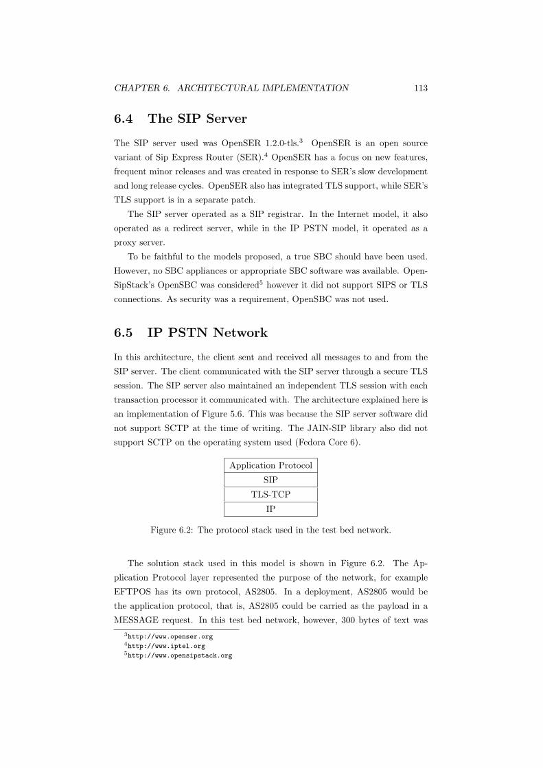
CHAPTER 6. ARCHITECTURAL IMPLEMENTATION 113
6.4 The SIP Server
The SIP server used was OpenSER 1.2.0-tls.3 OpenSER is an open source
variant of Sip Express Router (SER).4 OpenSER has a focus on new features,
frequent minor releases and was created in response to SER’s slow development
and long release cycles. OpenSER also has integrated TLS support, while SER’s
TLS support is in a separate patch.
The SIP server operated as a SIP registrar. In the Internet model, it also
operated as a redirect server, while in the IP PSTN model, it operated as a
proxy server.
To be faithful to the models proposed, a true SBC should have been used.
However, no SBC appliances or appropriate SBC software was available. Open-
SipStack’s OpenSBC was considered5 however it did not support SIPS or TLS
connections. As security was a requirement, OpenSBC was not used.
6.5 IP PSTN Network
In this architecture, the client sent and received all messages to and from the
SIP server. The client communicated with the SIP server through a secure TLS
session. The SIP server also maintained an independent TLS session with each
transaction processor it communicated with. The architecture explained here is
an implementation of Figure 5.6. This was because the SIP server software did
not support SCTP at the time of writing. The JAIN-SIP library also did not
support SCTP on the operating system used (Fedora Core 6).
Application Protocol
SIP
TLS-TCP
IP
Figure 6.2: The protocol stack used in the test bed network.
The solution stack used in this model is shown in Figure 6.2. The Ap-
plication Protocol layer represented the purpose of the network, for example
EFTPOS has its own protocol, AS2805. In a deployment, AS2805 would be
the application protocol, that is, AS2805 could be carried as the payload in a
MESSAGE request. In this test bed network, however, 300 bytes of text was3http://www.openser.org4http://www.iptel.org5http://www.opensipstack.org

CHAPTER 6. ARCHITECTURAL IMPLEMENTATION 114
used as the MESSAGE payload, as the goal of this project was to define and
demonstrate a suitable protocol stack for short generic transaction networks as
opposed to implementing EFTPOS over IP.
The client created an INVITE for a transaction processor and sent it to
the SIP server (message 3 in Figure 6.3). The SIP server performed a look
up, and relayed the INVITE (4) to the transaction processor. The transaction
processor responded with a 200 OK (7), which was relayed back to the client,
which completed the handshake with an ACK request (13 and 14).
Figure 6.3: A typical exchange in the proxied IP PSTN model. This is an
implementation of the solution illustrated in Figure 5.6.
The client then sent a MESSAGE request with the transaction payload (15).
The SIP server relayed this to the transaction processor, which responded with
a 200 OK (17 and 18), to acknowledge it had received the MESSAGE request.
The transaction processor then checked whether the request was successful or
not, and sent its reply in the payload of a MESSAGE request (19). The SIP
server relayed this back to the client (20), which also responded with a 200 OK
(21 and 22). Regardless of whether the transaction was successful or not (for

CHAPTER 6. ARCHITECTURAL IMPLEMENTATION 115
example ‘insufficient funds’), the client ended the session by sending a BYE
request (23 and 24) for the transaction processor to the SIP server. When the
transaction processor received this, it responded with a 200 OK (25 and 26) and
the session was terminated.
The SIP server forked the client’s INVITE to each transaction processor that
had registered (4). The SIP server returned the first 200 OK it received to the
client (7). Thus the first transaction processor that replied with a 200 OK was
given the call. The client then responded with an ACK request which was sent
to the SIP server (13) and proxied to the transaction processor (14), to establish
the session. This provided a degree of load balancing as servers which respond
to a 200 OK first are less likely to be heavily loaded, and it is these servers
which accept the call.
When a transaction processor received an INVITE request, it replied with
a 100 TRYING message (6), then a 200 OK message (7). A 200 OK message is
classed as a final response, while 100 TRYING is a provisional response. RFC
3261 stipulates that proxies must return all 200 OK and other final responses
for a forked INVITE to the client, while provisional responses (such as 100
TRYING) do not need to be returned.
If the SIP server has not received a final response to its forked INVITE,
it can use a CANCEL request to cancel establishment of the session (9). If it
has received a final response, however, it must be passed back to the client,
which must use a BYE request to terminate the session; CANCEL requests can
only be used to cancel sessions for which no final response has been received.
Consequently, when a transaction processor responded with a 200 OK, the SIP
server relayed the response back to the client and sent CANCEL requests to
all the other transaction processors it forked INVITE requests to, in order to
terminate the pending INVITE requests.
Transaction processors could have returned 200 OK messages instead of 100
TRYING messages in response to an INVITE. However, if the SIP server had
forked to many servers which were online, it would have relayed many 200 OK
messages back to the client. The client would then need to ACK one 200 OK
response, and send a BYE request to every other 200 OK response it received.
If there were many servers online, this may have placed a heavy load on the
client. Thus 100 TRYING messages gave the SIP server an opportunity to
cancel requests, thereby relieving the client from having to send multiple BYE
requests for each online server which received a forked INVITE. TRYING and
other provisional messages are used to indicate that an operation is in progress; if
there were no provisional messages available, clients would only know the server

CHAPTER 6. ARCHITECTURAL IMPLEMENTATION 116
on the other end was online when the operation was completed. Operations
that require a slightly longer time maybe interpreted by the client as a timeout.
The SIP server forked the INVITE requests in parallel; it relayed the IN-
VITE message to every registered transaction processor simultaneously. The
first transaction processor to respond with a 200 OK accepted the call, re-
sulting in lower response times. The disadvantage is that multiple transaction
processors may respond with a 200 OK before the SIP server has a chance to
CANCEL the pending INVITE request. This placed responsibility on the client
to terminate the unnecessary sessions with BYE requests, which resulted in
extra load for the client.
The alternative was serial or sequential forking, where the SIP server sent the
INVITE to the transaction processors one at a time. If request failed, timed out
or the transaction processor went offline, the SIP server sent the INVITE to the
next registered server in the list. The advantage of this is that the client would
only ever receive one 200 OK in response to sending a single INVITE request.
The disadvantage is that transaction processors at the top of the list may have
gone offline before their registration had expired. The SIP server would then
contact the offline servers and wait for them to timeout before sending the
INVITE to the next one. This would have resulted in a longer response time.
Forking brings fault tolerance during the session initiation stage; if a trans-
action processor fails before its registration expires, the SIP server will have
forked other transaction processors (in the case of parallel forking) or will do so
when the current forked INVITE times out (in the case of sequential forking).
However, transaction processors can also fail during a transaction. Eventu-
ally the session will time out, signalling the failure of the transaction processor
to the client. As long as the transaction did not complete or commit, the client
will resend the INVITE to the SIP server, which will relay it to the next avail-
able transaction processor. If there were no available transaction processors, the
SIP server would redirect the client to another SIP server/SBC (described in
Section 6.6), which may have operational transaction processors registered with
it. Failure of all SIP servers/SBCs would constitute a major network disaster;
the SIP servers/SBCs are a crucial network infrastructure in this model. The
SIP servers/SBCs represent a central point of failure and are a drawback of this
architecture, as discussed in Section 5.2.2.
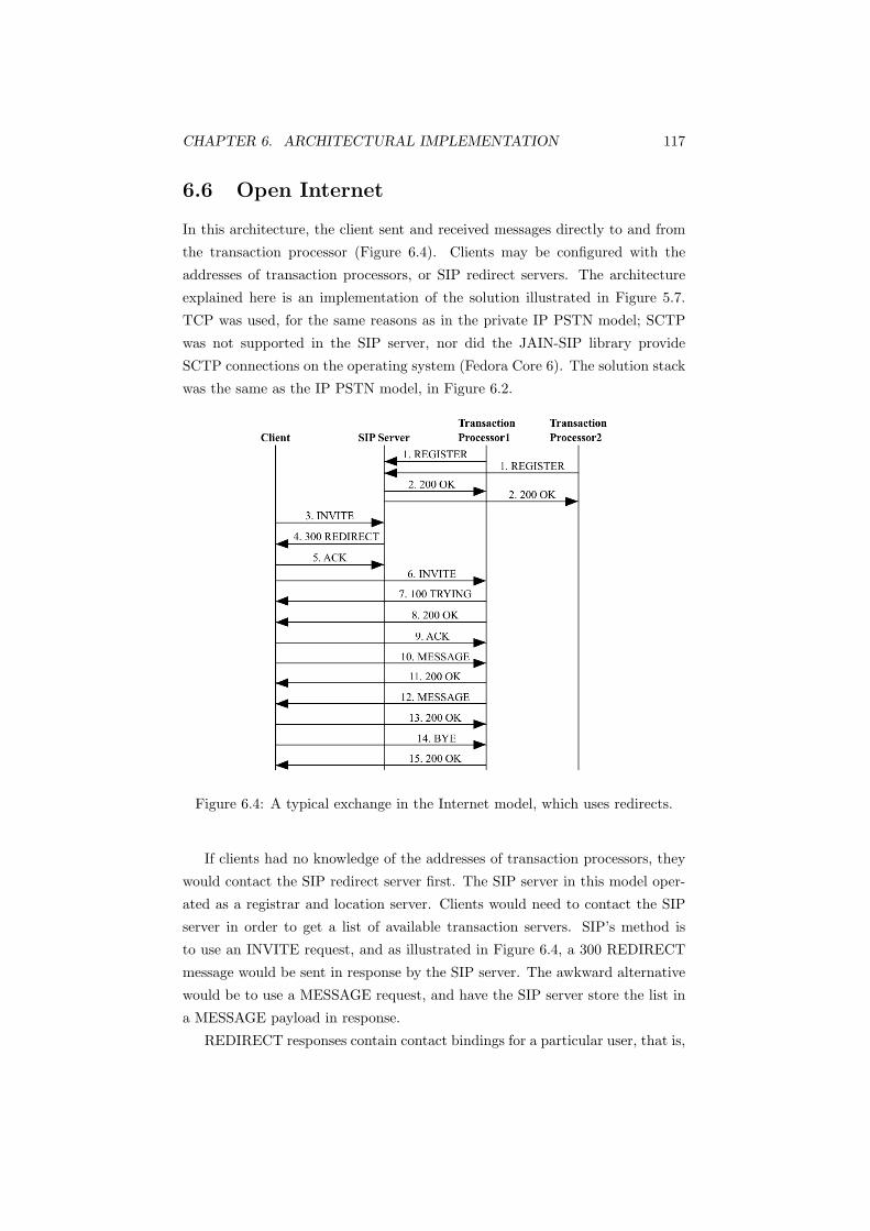
CHAPTER 6. ARCHITECTURAL IMPLEMENTATION 117
6.6 Open Internet
In this architecture, the client sent and received messages directly to and from
the transaction processor (Figure 6.4). Clients may be configured with the
addresses of transaction processors, or SIP redirect servers. The architecture
explained here is an implementation of the solution illustrated in Figure 5.7.
TCP was used, for the same reasons as in the private IP PSTN model; SCTP
was not supported in the SIP server, nor did the JAIN-SIP library provide
SCTP connections on the operating system (Fedora Core 6). The solution stack
was the same as the IP PSTN model, in Figure 6.2.
Figure 6.4: A typical exchange in the Internet model, which uses redirects.
If clients had no knowledge of the addresses of transaction processors, they
would contact the SIP redirect server first. The SIP server in this model oper-
ated as a registrar and location server. Clients would need to contact the SIP
server in order to get a list of available transaction servers. SIP’s method is
to use an INVITE request, and as illustrated in Figure 6.4, a 300 REDIRECT
message would be sent in response by the SIP server. The awkward alternative
would be to use a MESSAGE request, and have the SIP server store the list in
a MESSAGE payload in response.
REDIRECT responses contain contact bindings for a particular user, that is,

CHAPTER 6. ARCHITECTURAL IMPLEMENTATION 118
addresses of ‘users’ that have registered as transaction processors. The REDI-
RECT response can also include the address of other SIP servers. The client
stored this list internally, and sequentially forked INVITE requests until it lo-
cated an operational server. The client differentiated between a SIP server and
a transaction processor by the response it received in addition to the URI; if
it received a 200 OK in response to an INVITE request, it had contacted a
transaction processor.
The client could dispense with needing to create a session altogether and
send MESSAGES immediately as required. MESSAGE requests could be sent,
without first establishing a session with an INVITE request, even with no infor-
mation on available transaction servers. If this method was used, Message 3 in
Figure 6.4 would be a MESSAGE request instead of an INVITE request. A 300
REDIRECT message with contact bindings would still be sent in response. The
client would then repeat, sending the MESSAGE request to a server in the list.
However, using MESSAGE requests (which contain the sensitive transaction
details as a payload) to probe for online servers creates unnecessary risk.
Regardless of requiring strict two way TLS authentication (which ensures
the client is communicating with a trusted entity), revealing transaction pay-
load details unnecessarily to any network entity other than the proper receiving
transaction processor opens the possibility for fraud. For example while only
trusted infrastructure will have the required certificates to enable successful TLS
negotiation, the proxy software could be modified to record all traffic sent and
received. This would result in giving a trusted entity, which has nothing to do
with the processing of transactions, knowledge of the transaction data.
The subsequent messages exchanged are identical to the IP PSTN model,
except messages are sent directly to the transaction processor, instead of being
proxied through the SIP server.
If a transaction processor fails during the INVITE stage, the client will use
the next server in its list (TransactionProcessor2). If all the servers in the
list have been exhausted, the client will contact the SIP server again (as other
transaction processors may have come online since the last contact).
If transaction processors fail mid transaction, as long as the transaction did
not complete or commit, the client will start a new session with the next server
on the list. If the client tries all servers on the list without success, it will contact
the SIP server again to get an updated list. In this model, the SIP servers are
analogous to DNS servers, which provide a look up location service. If the SIP
redirect servers failed, as long as the addresses of the transaction processors
were known, the system would still function as usual. This is much like DNS,

CHAPTER 6. ARCHITECTURAL IMPLEMENTATION 119
where even if the DNS service failed, web browsing would still work if the IP
addresses were known.

Chapter 7
Architectural Validation
and Evaluation
7.1 Network Setup
The Client was a Pentium III 500MHz with 512MB RAM. The SIP server was a
Pentium 4 2.4GHz also with 512MB RAM. The Concentrator and Transaction
Processor were both Athlon 800MHz machines with 768MB RAM. The machines
were connected to a 10Mbps hub/Ethernet repeater to create an isolated LAN.
All of the computers ran Fedora Core 6 without running any other processes
which could have affected processor or network utilisation. Java 5.0 (1.5.0) was
used to run the client, concentrator and server software.
7.2 Experimental Design
As described in Section 1.1, this project’s main aim was to define a generic
IP based transaction architecture and demonstrate a proof of concept system.
Experiments were run to gauge the performance of each architecture. AES
and 3DES ciphers were used to encrypt, as 3DES is commonly implemented
in hand held payment terminals, while AES is commonly adopted as 3DES’s
successor. To avoid the effects of memory caching, disk paging and Java’s JIT
dynamic compilation optimisations, the first five readings of each experiment
were not recorded. Each experiment was then repeated 10 times with the times
recorded. Several experiments were conducted, and methodology for each are
detailed below. Results were analysed using ANOVA at the 95% confidence
interval.
120
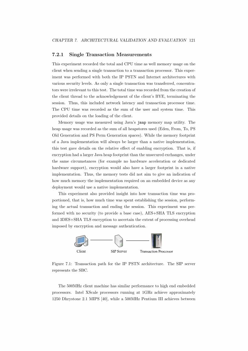
CHAPTER 7. ARCHITECTURAL VALIDATION AND EVALUATION 121
7.2.1 Single Transaction Measurements
This experiment recorded the total and CPU time as well memory usage on the
client when sending a single transaction to a transaction processor. This exper-
iment was performed with both the IP PSTN and Internet architectures with
various security levels. As only a single transaction was transferred, concentra-
tors were irrelevant to this test. The total time was recorded from the creation of
the client thread to the acknowledgement of the client’s BYE, terminating the
session. Thus, this included network latency and transaction processor time.
The CPU time was recorded as the sum of the user and system time. This
provided details on the loading of the client.
Memory usage was measured using Java’s jmap memory map utility. The
heap usage was recorded as the sum of all heapstores used (Eden, From, To, PS
Old Generation and PS Perm Generation spaces). While the memory footprint
of a Java implementation will always be larger than a native implementation,
this test gave details on the relative effect of enabling encryption. That is, if
encryption had a larger Java heap footprint than the unsecured exchanges, under
the same circumstances (for example no hardware acceleration or dedicated
hardware support), encryption would also have a larger footprint in a native
implementation. Thus, the memory tests did not aim to give an indication of
how much memory the implementation required on an embedded device as any
deployment would use a native implementation.
This experiment also provided insight into how transaction time was pro-
portioned, that is, how much time was spent establishing the session, perform-
ing the actual transaction and ending the session. This experiment was per-
formed with no security (to provide a base case), AES+SHA TLS encryption
and 3DES+SHA TLS encryption to ascertain the extent of processing overhead
imposed by encryption and message authentication.
Figure 7.1: Transaction path for the IP PSTN architecture. The SIP server
represents the SBC.
The 500MHz client machine has similar performance to high end embedded
processors. Intel XScale processors running at 1GHz achieve approximately
1250 Dhrystone 2.1 MIPS [40], while a 500MHz Pentium III achieves between
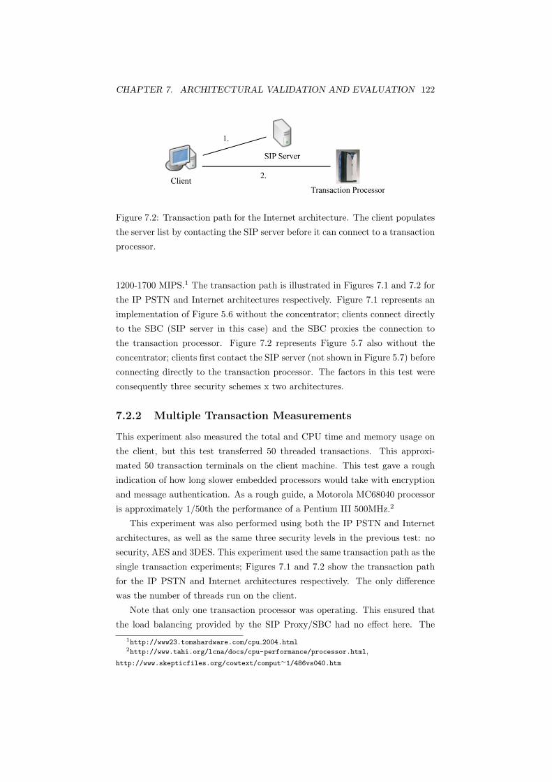
CHAPTER 7. ARCHITECTURAL VALIDATION AND EVALUATION 122
Figure 7.2: Transaction path for the Internet architecture. The client populates
the server list by contacting the SIP server before it can connect to a transaction
processor.
1200-1700 MIPS.1 The transaction path is illustrated in Figures 7.1 and 7.2 for
the IP PSTN and Internet architectures respectively. Figure 7.1 represents an
implementation of Figure 5.6 without the concentrator; clients connect directly
to the SBC (SIP server in this case) and the SBC proxies the connection to
the transaction processor. Figure 7.2 represents Figure 5.7 also without the
concentrator; clients first contact the SIP server (not shown in Figure 5.7) before
connecting directly to the transaction processor. The factors in this test were
consequently three security schemes x two architectures.
7.2.2 Multiple Transaction Measurements
This experiment also measured the total and CPU time and memory usage on
the client, but this test transferred 50 threaded transactions. This approxi-
mated 50 transaction terminals on the client machine. This test gave a rough
indication of how long slower embedded processors would take with encryption
and message authentication. As a rough guide, a Motorola MC68040 processor
is approximately 1/50th the performance of a Pentium III 500MHz.2
This experiment was also performed using both the IP PSTN and Internet
architectures, as well as the same three security levels in the previous test: no
security, AES and 3DES. This experiment used the same transaction path as the
single transaction experiments; Figures 7.1 and 7.2 show the transaction path
for the IP PSTN and Internet architectures respectively. The only difference
was the number of threads run on the client.
Note that only one transaction processor was operating. This ensured that
the load balancing provided by the SIP Proxy/SBC had no effect here. The
1http://www23.tomshardware.com/cpu 2004.html2http://www.tahi.org/lcna/docs/cpu-performance/processor.html,
http://www.skepticfiles.org/cowtext/comput∼1/486vs040.htm

CHAPTER 7. ARCHITECTURAL VALIDATION AND EVALUATION 123
time was recorded from the creation of the first thread to the termination of the
last session, while CPU time is again the sum of user and system time on the
client. The factors in this test were three security schemes x two architectures.
7.2.3 Impact of Concentrators
While the first two tests only measured total and CPU time as well as memory
usage on the client, this test also measured CPU time and memory usage on
the transaction processor. This test revealed whether a concentrator had any
benefit for transaction processors by hiding client connects/disconnects (as de-
scribed in Section 6.2). The client transferred 50 transactions as in the second
experiment. The architecture was not important here as the concentrator does
not care whether the transaction comes directly from a client terminal or a SIP
Proxy/SBC. Thus the Internet architecture was used in this test to remove any
effects the SIP Proxy may have had. When unconcentrated, the transaction
path is that depicted in Figure 7.2. Figure 7.3 shows the transaction path with
a concentrator. This set up represented an implementation of Figure 5.7. The
factors in this test were three security schemes x Concentrated/Unconcentrated.
Figure 7.3: Transaction path with concentrated sessions. The concentrator
maintains a persistent session with the transaction processor.
7.2.4 Recovery Time
This test demonstrated the feasibility of the recovery mechanism and measured
the time required to recover from a transaction server failure for the two ar-
chitectures. The CPU time on the client was also measured. Unlike the other
experiments where only one transaction processor was operating, this test had
two transaction processors operating. AES encryption was used for both tests
as security was not assumed to be a factor in recovery time. The client sent
a single transaction and the first transaction processor was made to fail after

CHAPTER 7. ARCHITECTURAL VALIDATION AND EVALUATION 124
receiving the MESSAGE request from the client. The opposing method would
be to have one server fail randomly, however this could have reduced the com-
parability between the two models. The transaction path is shown in Figures
7.4 and 7.5 for the IP PSTN and Internet models respectively.
Figure 7.4: Transaction path with transaction processor failure in the IP PSTN
architecture. After the client times out, it starts a new session. The SIP server
then proxies the transaction to the working transaction processor.
Figure 7.5: Transaction path with transaction processor failure in the Internet
architecture. After the client times out, it starts a new session with the next
transaction processor in the list.
While a transaction timeout of 5000ms was used for all previous experiments,
three timeout values were used here. Network architecture was also a factor in
this test. Therefore, the factors in this test were three timeout values x two
architectures. Testing with 50 threads would have given information on how the
architecture handled a relatively larger number of transactions, unfortunately
not all threads timed out properly.

Chapter 8
Results and Discussion
8.1 Single Transaction
In the first experiment, the client was configured to send one transaction using
both the IP PSTN and Internet architecture. Figure 8.1 shows the mean phase
and total times.
Figure 8.1: Mean times for a single transaction.
For a single transaction, the Internet architecture’s total time was slower.
This was due to the additional phase of populating the server list. This step
was not required in the IP PSTN model. Enabling encryption resulted in slower
125

CHAPTER 8. RESULTS AND DISCUSSION 126
Security Server List
Populated
Session Es-
tablished
Transaction
Completed
Session
Terminated
Total
Time
S.D.
Unsecured 112.9 94.1 160.5 84.6 452.1 17.9
AES 227.8 217.6 144.2 80.6 670.2 53.8
3DES 217.6 237.7 120.8 88.9 665.0 54.8
Table 8.1: Mean total times for a single transaction using the Internet model.
All figures are in ms.
Security Session Es-
tablished
Transaction
Completed
Session
Terminated
Total
Time
S.D.
Unsecured 132.6 173.3 80.2 386.1 54.9
AES 225.9 260.2 79.8 565.9 46.7
3DES 228.4 251.2 75.3 557.8 54.1
Table 8.2: Mean total times for a single transaction using the IP PSTN model.
All figures are in ms.
times for both architectures.
The differences between the architectures were statistically significant (F1,54 =
53.70, p < 0.01) as were the differences between the encryption schemes (F2,54 =
106.84, p < 0.01). The mean values for each phase are in Table 8.1 and 8.2 for
the Internet and IP PSTN architectures respectively. There was no statistically
significant interaction between architecture and the encryption scheme.
Figure 8.2 shows the mean CPU times used. The CPU times mirror the total
times; the Internet architecture required more CPU time than the IP PSTN
architecture due to the additional phase of discovering available transaction
processors. Enabling encryption also resulted in more CPU time used for both
architectures.
Again the differences between the architectures for CPU time used were
Security Internet S.D. IP PSTN S.D.
Unsecured 260.4 19.0 224.0 30.8
AES 374.8 20.1 343.2 19.0
3DES 384.4 25.7 337.7 22.1
Table 8.3: Mean client CPU times for a single transaction. All figures are in
ms.
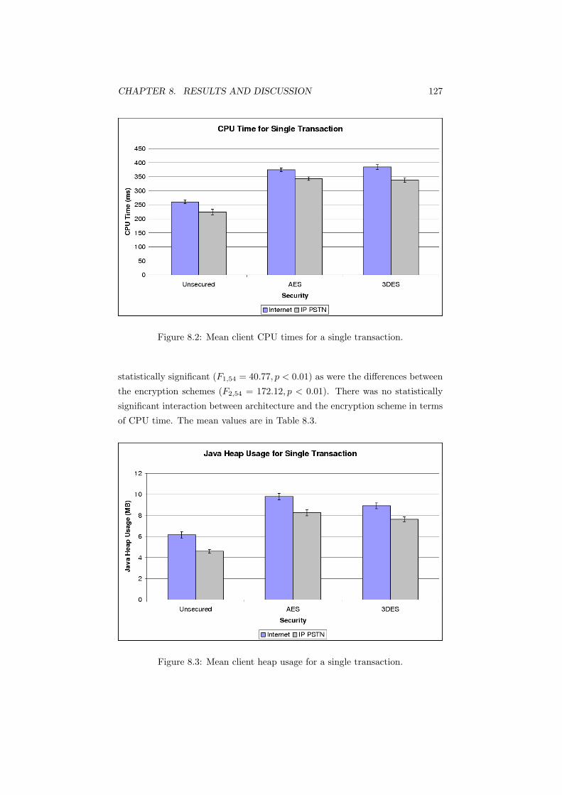
CHAPTER 8. RESULTS AND DISCUSSION 127
Figure 8.2: Mean client CPU times for a single transaction.
statistically significant (F1,54 = 40.77, p < 0.01) as were the differences between
the encryption schemes (F2,54 = 172.12, p < 0.01). There was no statistically
significant interaction between architecture and the encryption scheme in terms
of CPU time. The mean values are in Table 8.3.
Figure 8.3: Mean client heap usage for a single transaction.
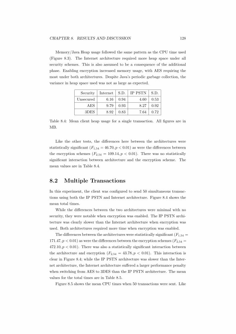
CHAPTER 8. RESULTS AND DISCUSSION 128
Memory/Java Heap usage followed the same pattern as the CPU time used
(Figure 8.3). The Internet architecture required more heap space under all
security schemes. This is also assumed to be a consequence of the additional
phase. Enabling encryption increased memory usage, with AES requiring the
most under both architectures. Despite Java’s periodic garbage collection, the
variance in heap space used was not as large as expected.
Security Internet S.D. IP PSTN S.D.
Unsecured 6.16 0.94 4.60 0.53
AES 9.79 0.93 8.27 0.92
3DES 8.92 0.83 7.64 0.72
Table 8.4: Mean client heap usage for a single transaction. All figures are in
MB.
Like the other tests, the differences here between the architectures were
statistically significant (F1,54 = 46.70, p < 0.01) as were the differences between
the encryption schemes (F2,54 = 109.14, p < 0.01). There was no statistically
significant interaction between architecture and the encryption scheme. The
mean values are in Table 8.4.
8.2 Multiple Transactions
In this experiment, the client was configured to send 50 simultaneous transac-
tions using both the IP PSTN and Internet architecture. Figure 8.4 shows the
mean total times.
While the differences between the two architectures were minimal with no
security, they were notable when encryption was enabled. The IP PSTN archi-
tecture was clearly slower than the Internet architecture when encryption was
used. Both architectures required more time when encryption was enabled.
The differences between the architectures were statistically significant (F1,54 =
171.47, p < 0.01) as were the differences between the encryption schemes (F2,54 =
472.10, p < 0.01). There was also a statistically significant interaction between
the architecture and encryption (F2,54 = 43.78, p < 0.01). This interaction is
clear in Figure 8.4; while the IP PSTN architecture was slower than the Inter-
net architecture, the Internet architecture suffered a larger performance penalty
when switching from AES to 3DES than the IP PSTN architecture. The mean
values for the total times are in Table 8.5.
Figure 8.5 shows the mean CPU times when 50 transactions were sent. Like

CHAPTER 8. RESULTS AND DISCUSSION 129
Figure 8.4: Mean times for 50 transactions.
Security Internet S.D. IP PSTN S.D.
Unsecured 3244.1 460.8 3250.1 409.5
AES 6557.0 818.8 10187.7 810.9
3DES 7572.5 782.2 10577.6 502.7
Table 8.5: Mean total times for 50 simultaneous transactions. All figures are in
ms.
the single transaction experiment, the CPU times mirrored the total times. The
IP PSTN model was slower than the Internet architecture when encryption was
enabled. Encryption required more CPU time in both architectures.
The differences in CPU time between the architectures were statistically
significant (F1,54 = 32.93, p < 0.01) as were the differences between the encryp-
tion schemes (F2,54 = 302.05, p < 0.01). The interaction between the archi-
tecture and encryption was also statistically significant in terms of CPU time
(F2,54 = 8.67, p < 0.01). This effect is the same as the interaction in the to-
tal times; the Internet architecture had a larger performance degradation when
moving from AES to 3DES than when the IP PSTN architecture was used. The
mean values for the CPU times are in Table 8.6.
Heap usage (Figure 8.6), surprisingly, did not follow the same pattern as
total and CPU time. While enabling encryption increased the memory used,
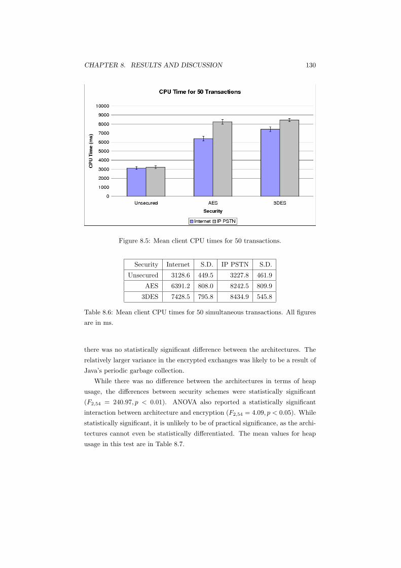
CHAPTER 8. RESULTS AND DISCUSSION 130
Figure 8.5: Mean client CPU times for 50 transactions.
Security Internet S.D. IP PSTN S.D.
Unsecured 3128.6 449.5 3227.8 461.9
AES 6391.2 808.0 8242.5 809.9
3DES 7428.5 795.8 8434.9 545.8
Table 8.6: Mean client CPU times for 50 simultaneous transactions. All figures
are in ms.
there was no statistically significant difference between the architectures. The
relatively larger variance in the encrypted exchanges was likely to be a result of
Java’s periodic garbage collection.
While there was no difference between the architectures in terms of heap
usage, the differences between security schemes were statistically significant
(F2,54 = 240.97, p < 0.01). ANOVA also reported a statistically significant
interaction between architecture and encryption (F2,54 = 4.09, p < 0.05). While
statistically significant, it is unlikely to be of practical significance, as the archi-
tectures cannot even be statistically differentiated. The mean values for heap
usage in this test are in Table 8.7.

CHAPTER 8. RESULTS AND DISCUSSION 131
Figure 8.6: Mean client heap usage for 50 transactions.
Security Internet S.D. IP PSTN S.D.
Unsecured 9.12 0.35 8.90 0.77
AES 26.95 2.87 23.91 4.08
3DES 25.67 3.29 27.77 3.49
Table 8.7: Mean client heap usage for 50 transactions. All figures are in MB.
8.3 Impact of Concentrators
While this experiment measured the total and CPU time as well as memory
usage on the client like the previous two, the CPU time and memory usage
on the transaction processor was measured as well. The client was configured
to send 50 simultaneous transactions using the Internet architecture, with and
without concentrators. Figure 8.7 shows the mean CPU time on the transaction
processor.
The impact of a concentrator is clear in Figure 8.7; concentrating sessions
onto a single session reduced the CPU time on the transaction processor by
almost half in the instance of no security, and by over two thirds when security
was enabled. Security had significantly less impact on the CPU time required
when the sessions were concentrated.
The differences between concentrated and unconcentrated connections was
statistically significant (F1,54 = 1041.36, p < 0.01), as were the differences be-
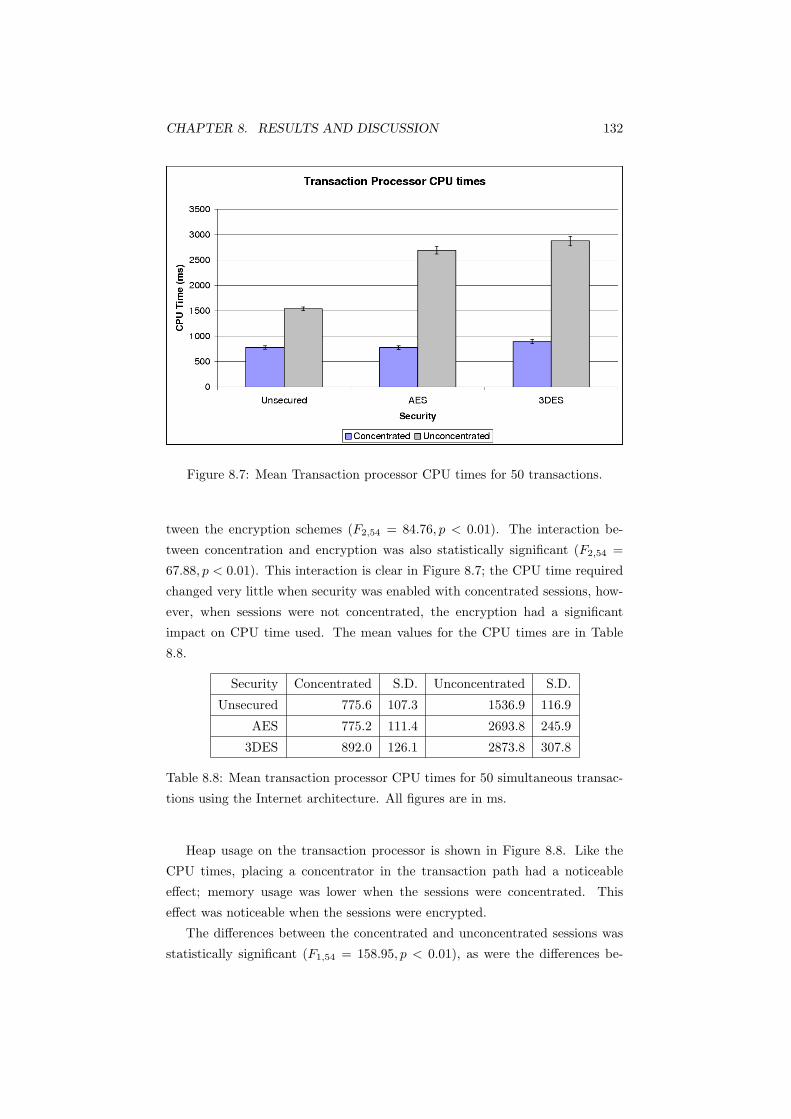
CHAPTER 8. RESULTS AND DISCUSSION 132
Figure 8.7: Mean Transaction processor CPU times for 50 transactions.
tween the encryption schemes (F2,54 = 84.76, p < 0.01). The interaction be-
tween concentration and encryption was also statistically significant (F2,54 =
67.88, p < 0.01). This interaction is clear in Figure 8.7; the CPU time required
changed very little when security was enabled with concentrated sessions, how-
ever, when sessions were not concentrated, the encryption had a significant
impact on CPU time used. The mean values for the CPU times are in Table
8.8.
Security Concentrated S.D. Unconcentrated S.D.
Unsecured 775.6 107.3 1536.9 116.9
AES 775.2 111.4 2693.8 245.9
3DES 892.0 126.1 2873.8 307.8
Table 8.8: Mean transaction processor CPU times for 50 simultaneous transac-
tions using the Internet architecture. All figures are in ms.
Heap usage on the transaction processor is shown in Figure 8.8. Like the
CPU times, placing a concentrator in the transaction path had a noticeable
effect; memory usage was lower when the sessions were concentrated. This
effect was noticeable when the sessions were encrypted.
The differences between the concentrated and unconcentrated sessions was
statistically significant (F1,54 = 158.95, p < 0.01), as were the differences be-

CHAPTER 8. RESULTS AND DISCUSSION 133
Figure 8.8: Mean transaction processor memory usage for 50 transactions.
tween the encryption schemes (F2,54 = 60.10, p < 0.01). There was also a sta-
tistically significant interaction between concentration and encryption (F2,54 =
26.05, p < 0.01). This effect was similar to the interaction in the transaction
processor CPU times. The heap usage almost doubled when encryption was
enabled in the unconcentrated sessions. The same increase in concentrated ses-
sions was significantly less. Table 8.9 contains the mean values.
Security Concentrated S.D. Unconcentrated S.D.
Unsecured 5.69 1.23 6.41 1.26
AES 6.93 0.99 12.36 1.36
3DES 6.74 0.91 11.53 0.89
Table 8.9: Mean transaction processor memory usage for 50 transactions. All
figures are in MB.
Figure 8.9 shows the impact of concentration on the total time required for
50 transactions on the client. The differences between concentrating and not
concentrating sessions were not statistically significant. Like in the previous
experiments, the differences between the encryption schemes were statistically
significant (F2,54 = 132.55, p < 0.01). There was no statistically significant
interaction between concentration and encryption. The mean values for the
total times are in Table 8.10.

CHAPTER 8. RESULTS AND DISCUSSION 134
Figure 8.9: Mean times for 50 transactions.
Security Concentrated S.D. Unconcentrated S.D.
Unsecured 3344.6 515.4 3244.1 460.8
AES 6479.0 940.2 6557.0 818.8
3DES 6806.7 1131.9 7572.5 782.2
Table 8.10: Mean total times for 50 simultaneous transactions using the Internet
architecture. All figures are in ms.
Figure 8.10 shows the impact of concentration on the CPU time used by the
client. The CPU times echo the total times; the differences between concen-
trating and not concentrating were not statistically significant. The differences
between encryption schemes, however, were statistically significant (F2,54 =
132.41, p < 0.01). There was no statistically significant interaction between
concentration and encryption. The mean values for the CPU times are in Table
8.11.
The effect of concentration on the client’s heap usage was similar (Figure
8.11); there were no statistically significant differences between concentrating
and not concentrating sessions. Differences between the security schemes were
statistically significant (F2,54 = 225.18, p < 0.01). There was a statistically
significant interaction between concentrating and security reported by ANOVA
(F2,54 = 3.37, p < 0.05). However, as the concentrations cannot even be sta-

CHAPTER 8. RESULTS AND DISCUSSION 135
Figure 8.10: Mean client CPU times for 50 transactions.
Security Concentrated S.D. Unconcentrated S.D.
Unsecured 3273.8 526.7 3128.6 449.5
AES 6343.6 885.3 6391.2 808.0
3DES 6658.0 1124.0 7428.5 795.8
Table 8.11: Mean client CPU times for 50 simultaneous transactions using the
Internet architecture. All figures are in ms.
tistically differentiated, the effect of this interaction is small. The mean heap
usage for the client are in Table 8.12.
Security Concentrated S.D. Unconcentrated S.D.
Unsecured 8.96 0.52 9.12 0.35
AES 24.41 4.30 26.95 2.87
3DES 28.00 3.87 25.67 3.29
Table 8.12: Mean client heap usage for 50 transactions. All figures are in MB.
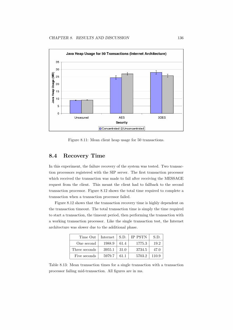
CHAPTER 8. RESULTS AND DISCUSSION 136
Figure 8.11: Mean client heap usage for 50 transactions.
8.4 Recovery Time
In this experiment, the failure recovery of the system was tested. Two transac-
tion processors registered with the SIP server. The first transaction processor
which received the transaction was made to fail after receiving the MESSAGE
request from the client. This meant the client had to fallback to the second
transaction processor. Figure 8.12 shows the total time required to complete a
transaction when a transaction processor failed.
Figure 8.12 shows that the transaction recovery time is highly dependent on
the transaction timeout. The total transaction time is simply the time required
to start a transaction, the timeout period, then performing the transaction with
a working transaction processor. Like the single transaction test, the Internet
architecture was slower due to the additional phase.
Time Out Internet S.D. IP PSTN S.D.
One second 1988.9 61.4 1775.3 19.2
Three seconds 3955.1 31.0 3734.5 47.0
Five seconds 5979.7 61.1 5703.2 110.9
Table 8.13: Mean transaction times for a single transaction with a transaction
processor failing mid-transaction. All figures are in ms.
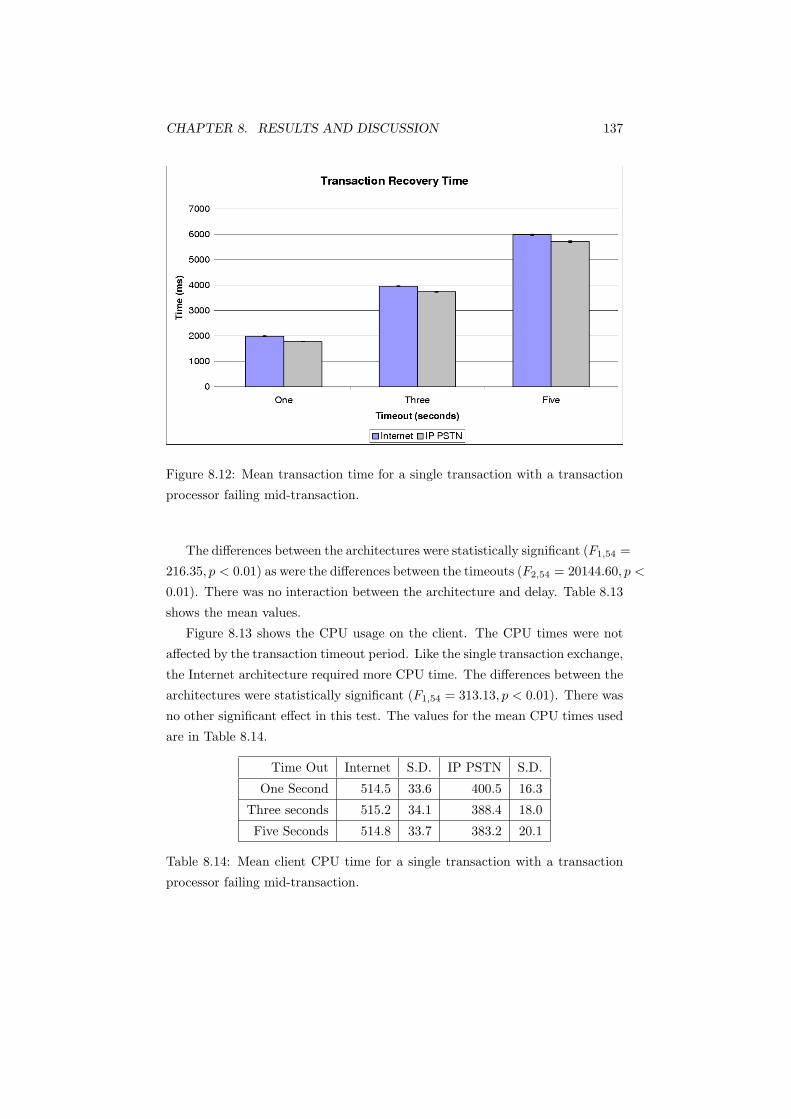
CHAPTER 8. RESULTS AND DISCUSSION 137
Figure 8.12: Mean transaction time for a single transaction with a transaction
processor failing mid-transaction.
The differences between the architectures were statistically significant (F1,54 =
216.35, p < 0.01) as were the differences between the timeouts (F2,54 = 20144.60, p <
0.01). There was no interaction between the architecture and delay. Table 8.13
shows the mean values.
Figure 8.13 shows the CPU usage on the client. The CPU times were not
affected by the transaction timeout period. Like the single transaction exchange,
the Internet architecture required more CPU time. The differences between the
architectures were statistically significant (F1,54 = 313.13, p < 0.01). There was
no other significant effect in this test. The values for the mean CPU times used
are in Table 8.14.
Time Out Internet S.D. IP PSTN S.D.
One Second 514.5 33.6 400.5 16.3
Three seconds 515.2 34.1 388.4 18.0
Five Seconds 514.8 33.7 383.2 20.1
Table 8.14: Mean client CPU time for a single transaction with a transaction
processor failing mid-transaction.

CHAPTER 8. RESULTS AND DISCUSSION 138
Figure 8.13: Mean client CPU time for a single transaction with a transaction
processor failing mid-transaction.
8.5 Discussion
In the single transaction experiments, the Internet architecture was slower than
the IP PSTN model. This was because it had the additional phase of populating
the server list and negotiating two sessions: one with the SIP server, then
another with the transaction processor. In the instance of a single transaction,
this had a larger performance impact than having to maintain two sessions at
the proxy; consequently, the Internet model placed a smaller load on the SIP
proxy.
In the 50 transaction experiments, however, the Internet architecture was
faster than the IP PSTN model as the messages did not need to be proxied. The
IP PSTN model placed extra load on the SIP server and had additional latency
because the messages were proxied. The larger volume of proxied transactions
had a greater effect on transaction time than the impact of the Internet model’s
additional phase of populating the server list. A faster SIP proxy may have
alleviated this.
Using concentrators to aggregate multiple SIP sessions onto a single session
reduced the load on the transaction processor in terms of CPU time. Doing this
improves the scalability and reliability of the transaction processor. Despite
the introduction of an additional entity in the transaction path, concentrating
CHAPTER 8. RESULTS AND DISCUSSION 139
sessions had no statistically significant impact on the transaction time, CPU
time or heap usage on the client.
In all experiments, enabling encryption increased the transaction time as well
as memory usage. AES was generally faster than 3DES. This has been verified
in other studies [84, 86, 122], which found that AES provided faster performance
than 3DES. Research showed that, as AES was less processor intensive, it had
lower energy consumption [98], which is an important factor in battery life in
mobile embedded devices. AES had a larger memory footprint than 3DES in
the single transaction exchange; it was found that AES code was larger than
3DES code, but a dedicated hardware solution would reduce this [86].
The heap usage on the client in the 50 transaction exchanges (Figures 8.6
and 8.11) was affected differently by the security schemes, architecture and con-
centration. For instance, Figure 8.6 shows that, when encrypted with AES,
the Internet architecture appeared to use more heap space than the IP PSTN
architecture. However, this was reversed when the encryption was changed to
3DES. A similar, although opposite, pattern appeared on the client with con-
centrated/unconcentrated sessions. Despite the appearance of differences, the
large variance made any differences statistically insignificant. The large variance
was probably due to Java’s periodic garbage collection; the heap usage increases
until a garbage collection is performed. This made accurate measurements of
memory usage difficult.
Recovery time was found to be highly dependent on the transaction time-
out. When the timeout was low, the transaction recovered from transaction
processor failure faster. However, this test did not examine stress loading on
the transaction processors because when the client was run with a relatively
large number of threads, for example 50, not all threads timed out according to
the specified timeout and instead fell back to the SIP timeout. The standard
SIP timeout is approximately 32 seconds, which was considered too long for this
project.
These results demonstrate that the proposed solution stack on either network
model provides a viable architecture on which to run a transaction network.
The slowest transaction time, 50 transactions using 3DES encryption on the
IP PSTN model, was 10.6 seconds. This is below the current system’s total
transaction time of 15 seconds, as noted in Section 2.1.
8.5.1 Single Transactions
When the client was sending a single transaction, the IP PSTN model was faster.
This was because the Internet model had the additional step of populating the

CHAPTER 8. RESULTS AND DISCUSSION 140
server list. In the IP PSTN model, the SIP server operated as a proxy and
performed this step on behalf of the client. However, Figure 8.1 shows that,
without the additional step, the same set of phases in the Internet model was
faster than the corresponding phase in the IP PSTN architecture. While the
differences between the architectures were small, they may be significant on an
embedded device with limited processing ability.
The Internet model also had to negotiate two TLS connections (two TCP
connections in the unsecured test): one with the SIP server/registrar and an-
other with the transaction processor. In contrast, a client in the IP PSTN model
only needed to negotiate a single TLS connection with the SBC/SIP Proxy. TLS
connection negotiation used approximately a third of the total connection time
in these instances. This additional phase accounted for the Internet model’s
higher CPU time and larger heap usage.
In the IP PSTN model, over one third of the time was spent on establishing
the single TLS connection. With the Internet model, almost half, and in the
instance of encrypted sessions, over two thirds, of the total time was spent
establishing the sessions - this consisted of populating the server list and the
actual session establishment. In a high volume transaction environment, the
benefit of a concentrated, persistent session is clear; a session does not need
to be established for each transaction. Rather than having to establish a new
session upon each request, a concentrator can forward transactions on the session
it maintains with the transaction processor.
This benefit mainly applies to proxies such as SIP servers and concentrators,
as the transaction rate from a single transaction terminal is still low, that is, only
a single person can use a transaction terminal at a time. If individual transaction
processors were to maintain persistent sessions with transaction processors, a
significantly larger amount of state stored on a transaction processor would be
required.
The transaction phase (the two MESSAGE request and OK response pairs)
when encrypted, required almost twice as much time in the IP PSTN architec-
ture than in the Internet architecture. This was due to the proxy behaviour
where the messages were handled twice. Thus even if the transaction processor
responded immediately, the response may have been delayed and held up at the
SIP proxy.
It is interesting to note that the transaction phase was slower when there
was no security in the Internet model. The delay between receiving the MES-
SAGE from the transaction processor and sending the 200 OK response was
substantially shorter in the secured exchanges than in the unsecured exchange.
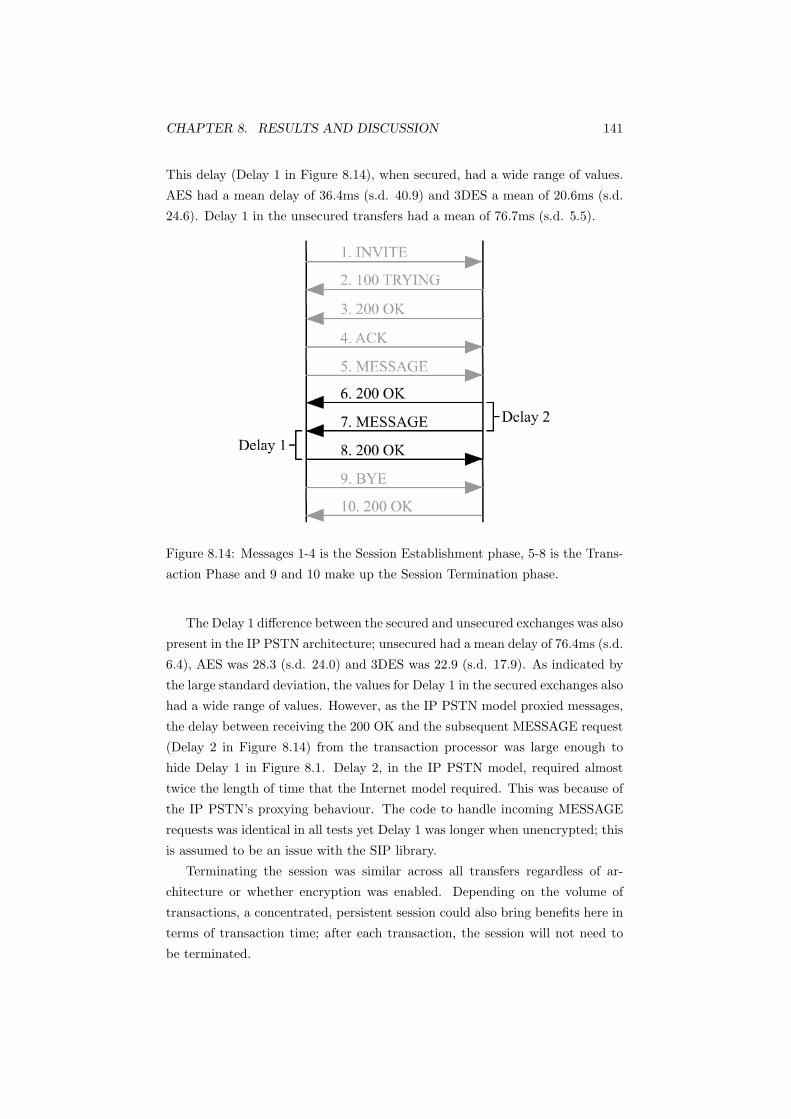
CHAPTER 8. RESULTS AND DISCUSSION 141
This delay (Delay 1 in Figure 8.14), when secured, had a wide range of values.
AES had a mean delay of 36.4ms (s.d. 40.9) and 3DES a mean of 20.6ms (s.d.
24.6). Delay 1 in the unsecured transfers had a mean of 76.7ms (s.d. 5.5).
Figure 8.14: Messages 1-4 is the Session Establishment phase, 5-8 is the Trans-
action Phase and 9 and 10 make up the Session Termination phase.
The Delay 1 difference between the secured and unsecured exchanges was also
present in the IP PSTN architecture; unsecured had a mean delay of 76.4ms (s.d.
6.4), AES was 28.3 (s.d. 24.0) and 3DES was 22.9 (s.d. 17.9). As indicated by
the large standard deviation, the values for Delay 1 in the secured exchanges also
had a wide range of values. However, as the IP PSTN model proxied messages,
the delay between receiving the 200 OK and the subsequent MESSAGE request
(Delay 2 in Figure 8.14) from the transaction processor was large enough to
hide Delay 1 in Figure 8.1. Delay 2, in the IP PSTN model, required almost
twice the length of time that the Internet model required. This was because of
the IP PSTN’s proxying behaviour. The code to handle incoming MESSAGE
requests was identical in all tests yet Delay 1 was longer when unencrypted; this
is assumed to be an issue with the SIP library.
Terminating the session was similar across all transfers regardless of ar-
chitecture or whether encryption was enabled. Depending on the volume of
transactions, a concentrated, persistent session could also bring benefits here in
terms of transaction time; after each transaction, the session will not need to
be terminated.

CHAPTER 8. RESULTS AND DISCUSSION 142
8.5.2 Multiple Transactions
The Internet model was faster than the IP PSTN architecture when the client
was made to send 50 transactions, in contrast to the single transaction tests,
where the Internet architecture’s additional phase caused it to be slower. Here,
the load imposed by the additional phase in the Internet model was eclipsed by
having to proxy the transaction in the IP PSTN model.
The effect of the proxy was evident in the secured exchanges. The proxy had
to maintain two TLS sessions for each client; one to the client and another to
the transaction processor. The additional latency of having to handle messages
twice also had an effect: CPU time is a smaller proportion of total time in the
IP PSTN model. This signified that the client had more idle time in the IP
PSTN architecture. This is because of the additional latency of waiting for the
request and response to be proxied back.
This did not explain, however, the increased CPU time in the IP PSTN ex-
changes; the IP PSTN’s CPU usage was higher than the corresponding exchange
in the Internet model. This increased CPU time was unexpected as the client in
the IP PSTN architecture sent fewer messages than in the Internet architecture;
thus, fewer messages had to be handled and secured. It was possible that the
SIP library did not relinquish the CPU when waiting for a response.
To investigate this, an additional test was run. The aim was to investigate
whether the SIP library/JVM really did relinquish the CPU when waiting for a
response. The Internet architecture with AES encryption was used. The client
was run with 10 threads and the CPU time was recorded. This was repeated
15 times. The transaction processor software was then modified to wait 1000ms
before responding to a request. The client was run again with 10 threads.
Without the 1000ms delay, the client CPU time was 1220.6ms (s.d. 213.5).
When the transaction processor had the delay, the CPU time on the client
increased to 1542.2ms (s.d. 265.5). This difference was statistically significant
(t28 = 13.37, p < 0.01). This result showed that, despite exchanging the same
messages, when the transaction processor was delayed, the client continued to
use a small amount of CPU time when apparently idle.
This explained the increased CPU usage in the IP PSTN model. There was
more idle time in the IP PSTN model, due to the proxying behaviour. Idle time
contributed a small amount of CPU time, resulting in a higher CPU time. This
effect is probably only present when the client is executed with multiple threads;
the CPU time used did not change in the recovery tests with different timeouts.
This was because the recovery tests were run with only a single thread.
There was a statistically significant interaction between architecture and
CHAPTER 8. RESULTS AND DISCUSSION 143
encryption. The Internet model experienced a noticeable increase in total and
client CPU time when switching from AES to 3DES; the IP PSTN model had
little difference. As noted above, there was more idle time in the IP PSTN model
than in the Internet model. The SIP server was a Pentium 4 2.4GHz, while the
transaction processor was an Athlon 800MHz. This suggested the transaction
processor was the bottleneck; the SIP server was forwarding and processing
requests faster than the transaction processor could handle them. This meant
the SIP server and therefore the client were waiting on the transaction processor
to return responses. Switching from AES to the more processor intensive 3DES
meant less idle time on the SIP server. That is, some of the server’s idle time in
AES was consumed as CPU time when switching to 3DES, resulting in a similar
total transaction time.
Contrast this with the Internet model. The client and transaction processor
communicated with each other directly after populating the server list. Any
increase in processing time on either end resulted in an overall increase in time.
As 3DES is a more processor intensive cipher, client CPU time increased, as
indicated in Figure 8.5. Total time increased as well because the transaction
processor took longer to respond as a result of the slower cipher.
There was no statistically significant difference between the two architectures
in terms of heap usage. This was because with a larger number of threads, a
larger proportion of the heap would have been used to store objects; with the
single transaction test, a larger proportion of the heap would have been used
to store classes. That is, once the classes have been loaded, the cost of storing
additional objects is low. This explains that despite sending 50 times more
transactions with 50 times more threads, heap usage only increased by half
in the unsecured transactions and only approximately tripled in the secured
exchanges.
8.5.3 Impact of Concentrators
Concentrating sessions onto a single session to the transaction processor signifi-
cantly reduced the CPU time and heap space used on the transaction processor.
This was expected, as the transaction processor no longer had to deal with in-
coming sessions, their termination or allocate memory for their maintenance.
The transaction processor maintained a single persistent session with the con-
centrator and only had to deal with the actual MESSAGE requests.
There was a statistically significant interaction between concentration and
encryption. When the sessions were concentrated, there was little change in
the CPU time required on the transaction processor. Heap usage increased
CHAPTER 8. RESULTS AND DISCUSSION 144
by a relatively small amount as well. However, the CPU time required with
unconcentrated sessions increased significantly when encryption was enabled.
Memory usage, in the encrypted exchanges, almost doubled. There were several
factors which caused this. One was that the transaction processor simply did not
need to maintain a session for each client; it only maintained a single session with
the concentrator. This reduced the amount of state required by the operating
system to maintain network connections. The second was that since sessions
did not need to be created and terminated, fewer packets were exchanged. This
included the INVITE and BYE sequences. Fewer packets meant the transaction
processor did not need to encrypt as much traffic, resulting in less CPU time
used.
Concentrating sessions had no performance impact on the client. That is,
when the sessions were concentrated, total time, CPU time and heap usage
could not be statistically differentiated from the unconcentrated sessions. This
was despite having the concentrator positioned in the transaction path.
A concentrator reduces the processing load and memory usage on a transac-
tion processor while serving the same number of clients. This enables the same
transaction processor to process transactions from more clients than if sessions
were not concentrated. This can reduce costs as well as improve reliability; if
the transaction processor is not running at full load, the additional spare pro-
cessing capacity means it can still process transactions in the event of a sudden
jump in transaction rate. These benefits come at no cost to the client.
8.5.4 Recovery Time
Recovery time for a single transaction was found to be highly dependent on
the transaction timeout. Total transaction time was approximately 700-1000ms
(the normal time required for a single transaction) added onto the transaction
timeout value. The Internet architecture’s additional phase caused it to have a
longer transaction time, resulting in a longer recovery time than when the IP
PSTN model was used. When compared to the total transaction time (includ-
ing the transaction timeout), however, the extra time required for the Internet
model’s additional phase was small. This test demonstrated the fault tolerance
mechanism of the solution stack was indeed viable.
CPU time on the client was unaffected by the transaction timeout value.
Like in the single transaction test, the CPU time was higher when the Internet
model was used because of the additional phase. CPU usage was higher (when
a transaction processor failed) than the CPU times in the single transaction test
as the client had to establish a session with a different transaction processor and

CHAPTER 8. RESULTS AND DISCUSSION 145
retransmit the transaction after failure of the first transaction processor.
A test with 50 parallel transactions was not performed. This was because the
timeout task associated for each thread did not work correctly on all threads.
When this timeout task failed, the corresponding thread would wait for the SIP
timeout before timing out (approximately 32 seconds). The standard SIP time-
out is defined in RFC 3261 as 64 * the retransmit time (usually 500ms). SIP’s
retransmit timer, however, is defined for UDP and other unreliable transports,
and retransmissions are not performed at the application layer when a reliable
transport protocol is used (such as TLS/TCP in this instance). Testing a large
number of parallel transactions would have provided details on the performance
of the transaction processor when subjected to a heavy load. These results
would have been dependent on the hardware used, nevertheless, they still would
have had value.
Transaction timeouts when set too low could potentially congest the net-
work. Clients could mistakenly assume a server was down when the cause of
the timeout was a latency spike. That is, clients may not be able to distin-
guish server failure and transaction queuing/processing delays. Further work
is required as the transaction timeout must be tuned to the latencies of the
network on which the transaction network is deployed. Transaction timeouts
would also depend on the processing capacity of the network, that is, the com-
bined transaction processing capacity. Transaction timeouts also need to keep
within reasonable levels of responsiveness, for example an EFTPOS terminal
must complete the transaction within reasonable time before the user finds the
wait too long.
8.5.5 Limitations
There were several major limitations with these experiments, however none of
them affected this project’s main goal of defining a protocol stack suitable for
short duration transactions. Some of these provide avenues for future work.
One assumption was that running 50 threaded transactions on the client
machine approximated a processor with 1/50th of the speed. This resulted in
the client maintaining 50 connections, instead of a processor 1/50th of the speed
maintaining a single connection. Therefore, the increased CPU time was not
only attributed to encrypting 50 times more data, but also administering 50
times the number of connections and sessions as well. Using an actual embed-
ded device with the processing capability typical of a hand held transaction
terminal would have provided the most accurate results. Fortunately, regard-
less of whether this assumption was valid or not, using 50 threaded sessions

CHAPTER 8. RESULTS AND DISCUSSION 146
provided details of the performance of the SIP server and transaction processor
when presented with a large number of simultaneous transactions.
Therefore, a major limitation of this project was the failure to assess the
solution stack on an actual embedded device. This would have provided accurate
details on the performance of the solution stack and the impact of encryption
on an embedded processor. Using an actual embedded device could also have
provided specific details such as power usage, memory consumption and code
size. However, this would have required a native implementation, which could
have increased development time.
Another limitation was that no SBC was actually used, despite it being a
crucial part of the IP PSTN architecture. This was because no appropriate SBC
was available as explained in Section 6.4. In its place was a SIP proxy server.
The SBC would have provided NAT traversal and would have broken the session
between the client and the transaction processor; as described in Section 5.2,
the clients address messages to the SBC and the SBC forwards these to the
destination. SBCs also provide firewall and authentication functionality. None
of these were tested in this project. Fortunately these factors were largely
external to the function of the protocol stack.
Related to this was the testbed network; it was too simple to represent
an actual deployment. In a real scenario, there would be various routers and
switches in the path, each adding their own processing and network latency. In
addition, there was no real network infrastructure, for example the transaction
processor simply returned 300 bytes of data, instead of connecting to a back
end database.
While transaction processor failure recovery tests were performed, there was
no stress testing of the network and of the transaction processors. This would
have provided details on the scalability of the network; while the system works
if a transaction processor fails mid-transaction for a single client, there are no
guarantees the system will continue to function when there are a large number
of simultaneous transactions in the network and a transaction processor fails.
SCTP was also a viable transport protocol for the solution stack. The SIP
library in conjunction with the operating system used, however, did not support
SCTP.
Finally these results are limited to the hardware used. Faster hardware will
give different results. While the absolute values may change, the relative values
are expected to be similar; if encryption, for example, requires more time than
unsecured exchanges, it is expected that encryption will still require more time
than the unsecured exchanges using different hardware.

Chapter 9
Conclusions
This research projected aimed to define a generic IP based protocol stack suit-
able for short duration transactions and to evaluate the performance of the
architectures. Enabling encryption expectedly increased CPU and heap usage
as well as time to complete the transaction.
The single transaction experiments approximated a high performance em-
bedded processor. While the differences in time between the two architectures
were small, the differences will be significant if: there are a large number of
transactions, or embedded devices with limited processing capability are used.
Here, the Internet model had slower performance because of the additional
phase.
In the multiple transaction tests, the IP PSTN model had slower perfor-
mance. This was despite the IP PSTN architecture sending fewer messages.
This slower performance was due to the proxying behaviour; messages were
handled twice, introducing more latency and processing time.
Using concentrators to aggregate multiple sessions onto a single session had a
significant impact on the transaction processor. When concentrated, the trans-
action processor had lower CPU and heap usage compared with unconcentrated
sessions. The cost of encryption was also considerably lower on the transaction
processor when the sessions were concentrated. Although the concentrator rep-
resented another entity in the network path and subsequently introduced more
latency and processing time, this had no effect on the total transaction or CPU
time used by the client.
Recovery time was found to be highly dependent on the transaction timeout
value. Further work needs to be completed to analyse the network availability
and reliability under heavy load conditions. This test, however, still demon-
strated that the solution stack was robust in the event of a transaction processor
147

CHAPTER 9. CONCLUSIONS 148
failure.
Further work includes assessing the solution stack on an actual embedded
device, to attain an indication of real world performance. A more complex
and comprehensive testbed network could also be used, to provide a more re-
alistic model of performance. This includes using an SBC appliance, back end
databases and additional routers and switches to introduce realistic latency
typical of WANs. While TCP was the only transport protocol used, SCTP was
also a candidate transport protocol. Measuring the performance using SCTP
in place of TCP as well as the additional reliability provided by multihoming
is another possibility. With wireless networks becoming more pervasive, work
could also be performed on the feasibility of wireless payment networks and the
security challenges introduced.
The proposed SIP based solution has been demonstrated to be a viable
protocol stack on both the open Internet and the controlled private network
model. Both architectures support transactions within reasonable time and
demonstrate the ability to recover in the event of transaction processor failure.
Bibliography
[1] Introduction to FreeS/WAN. http://www.freeswan.org/freeswan
trees/CURRENT-TREE/doc/ipsec.html, Accessed September 2006.
[2] Investigations about SSL. http://www.eucybervote.org/Reports/
MSI-WP2-D7V1-V1.0-02.htm, Accessed October 2006.
[3] Quick Transmission Protocol Frequently Asked Questions. Inetco, http:
//www.inetco.com/technology/qtpfaq.html, Accessed July 2006.
[4] SIP General Questions and Answers. SIP Center, http://
www.sipcenter.com/sip.nsf/html/General+Questions, Accessed July
2006.
[5] SIP versus H.323. iptel.org, http://www.iptel.org/info/trends/sip.
html, Accessed July 2006.
[6] Stream Control Transmission Protocol(SCTP). www.sctp.be, Accessed
July 2006.
[7] Universal TUN/TAP device driver Frequently Asked Questions. VTUN
Virtual Tunnelhttp://vtun.sourceforge.net/tun/faq.html, Accessed
October 2006.
[8] WSDL Tutorial. W3 Schools, http://w3schools.com/wsdl/default.
asp, Accessed Novemeber 2006.
[9] Survivable Adaptable Fiber Optic Network. U.S. Department of Defense
Military Standard MIL-STD-2204, October 1992.
[10] Xpress Transport Protocol Specification. XTP Revision 4.0b, XTP Forum,
www.packeteer.com/resources/prod-sol/XTP.pdf, Accessed Novem-
ber 2006, 1998.
149

BIBLIOGRAPHY 150
[11] A New EFTPOS Paradigm. Hypercom Whitepaper, http:
//www.hypercom.com/Documents/whitepapers/EFTPOSParadigm.pdf,
Accessed April 2007, February 2000.
[12] Secure Shell version 1 vulnerabilities reported by CERT. SSH Commu-
nications Security, http://www.ssh.com/company/news/article/212/,
Accessed August 2006, November 2001.
[13] Security Requirements for Cryptographic Modules. National Institute
of Standards and Technology, http://csrc.nist.gov/publications/
fips/fips140-2/fips1402.pdf, May 2001.
[14] What is Point of Sale: What Happens When You Buy with Plastic. Hyper-
com Whitepaper, http://www.hypercom.com/Documents/whitepapers/
whatispointofsale.pdf, Accessed April 2007, April 2001.
[15] Session border controllers: Delivering interactive communications across
ip network borders. Acme Packet Whitepaper, http://www.acmepacket.
com/images/whitepaper SBC.pdf, Accessed January 2007, February
2003.
[16] Amendment 6: Medium Access Control (MAC) Security Enhancements.
ANSI/IEEE Std 802.11i, Institute of Electrical and Electronic Engineers,
2004.
[17] EFTPOS over DSL. White Label Networks Whitepaper, http://
homepage.powerup.com.au/∼squadron/EFTPOS/EFTPOS over DSL.pdf,
Accessed April 2007, February 2006.
[18] NAT Traversal for Multimedia over IP. Newport Networks Whitepaper,
http://www.newport-networks.com/cust-docs/33-NAT-Traversal.
pdf, Accessed January 2007, 2006.
[19] End to end data delivery using IBM WebSphere MQTT - applications for
SCADA. http://www.arcom.co.uk/products/pcp/Integration/End
to end data delivery with WebSphere MQTT.pdf, Accessed May 2007,
2007.
[20] Albrecht, C. C. How Clean is the Future of SOAP? Communications
of the ACM 47, 2 (February 2004), 66–68.
[21] Allman, M., Paxson, V., and Stevens, W. TCP Congestion Control.
RFC 2581, April 1999.

BIBLIOGRAPHY 151
[22] Alshamsi, A., and Saito, T. A Technical Comparison of IPSec and
SSL. In Advanced Information Networking and Applications, 2005. AINA
2005. 19th International Conference on (March 2005), vol. 2, pp. 395–398.
[23] Bauer, M. Paranoid Penguin: The 101 Uses of OpenSSH: Part 1. Linux
Journal 2001, 81 (January 2001).
[24] Bauer, M. Paranoid Penguin: Linux VPN technologies. Linux Journal
2005, 130 (February 2005).
[25] Bellovin, S., Ioannidis, J., Keromytis, A., and Stewart, R. On
the Use of Stream Control Transmission Protocol (SCTP) with IPsec.
RFC 3554, July 2003.
[26] Berger, T. Analysis of Current VPN Technologies. In Availability, Relia-
bility and Security, 2006. ARES 2006. The First International Conference
on (April 2006), p. 8.
[27] Bin, R., and Xiaolan, Z. Enhanced Transaction TCP - Design and
Implementation. Master’s thesis, School of Electronics and Information
Technology, Shanghai Jiaotong University, October 2002.
[28] Braden, R. Towards a Transport Service for Transaction Processing
Applications. RFC 955, September 1985.
[29] Braden, R. Requirements for Internet Hosts – Communication Layers.
RFC 1122, October 1989.
[30] Braden, R. T/TCP - TCP Extensions for Transactions. RFC 1644, July
1994.
[31] Bronson, S. VPN PPP-SSH Mini-HOWTO. In The Linux Documenta-
tion Project, http: // www. tldp. org/ HOWTO/ ppp-ssh (January 2002).
[32] Camarillo, G. SIP Demystified. McGraw-Hill, 2002.
[33] Camarillo, G., Kantola, R., and Schulzrinne, H. Evaluation of
Transport Protocols for the Session Initiation Protocol. IEEE Network
17, 5 (September - October 2003), 40–46.
[34] Campbell, B., Rosenberg, J., Schulzrinne, H., Huitema, C., and
Gurle, D. Session Initiation Protocol (SIP) Extension for Instant Mes-
saging. RFC 3428, December 2002.
BIBLIOGRAPHY 152
[35] Castelluccia, C., Mykletun, E., and Tsudik, G. Improving Secure
Server Performance by Re-balancing SSL/TLS Handshakes. In ASIACCS
’06: Proceedings of the 2006 ACM Symposium on Information, computer
and communications security (March 2006), pp. 26–34.
[36] Chatterjee, S., Abhichandani, T., Li, H., Tulu, B., and Byun,
J. Instant Messaging and Presence Technologies for College Campuses.
IEEE Network 19, 3 (May - June 2005), 4–13.
[37] Chavda, K. F. Anatomy of a Web Service. Journal of Computing Sci-
ences in Colleges 19, 3 (January 2004), 124–134.
[38] Cheriton, D. VMTP: Versatile Message Transaction Protocol. RFC
1045, February 1988.
[39] Cheriton, D. R., and Williamson, C. L. VMTP as the Transport
Layer for High-Performance Distributed Systems. IEEE Communications
Magazine 27, 6 (June 1989), 37–44.
[40] Chinnery, D. G., and Keutzer, K. Closing the power gap between
asic and custom: An asic perspective. In DAC ’05: Proceedings of the
42nd annual conference on Design automation (June 2005), pp. 275–280.
[41] Conover, J. SSL VPN: IPSec Killers or Overkill? CIO (October 2003).
[42] Conrad, P., Ramalho, M., Stewart, R., Tuexen, M., and Xie,
Q. Stream Control Transmission Protocol (SCTP) Partial Reliability Ex-
tension. RFC 3758, May 2004.
[43] Cornish, A., Cox, M., Neill, R., Palmer, I., Telfer, A.,
Wignell, C., and Young, C. Quick Transaction Protocol -
QTP. IETF Draft, http://www.faqs.org/ftp/internet-drafts/
draft-cornish-qtp-05.txt, expired May 2005, October 2002.
[44] Day, M., Aggarwal, S., Mohr, G., and Vincent, J. Instant Mes-
saging / Presence Protocol Requirements. RFC 2779, February 2000.
[45] Day, M., Rosenberg, J., and Sugano, H. A Model for Presence and
Instant Messaging. RFC 2778, February 2000.
[46] de Vivo, M., de Vivo, G. O., Koeneke, R., and Isern, G. Internet
Vulnerabilities Related to TCP/IP and T/TCP. In ACM SIGCOMM
Computer Communication Review (January 1999), vol. 29, pp. 81–85.
BIBLIOGRAPHY 153
[47] Dierks, T., and Allen, C. The TLS Protocol Version 1.0. RFC 2246,
January 1999.
[48] Dierks, T., and Rescorla, E. The Transport Layer Security (TLS)
Protocol Version 1.1. RFC 4346, April 2006.
[49] Eastlake, D. Cryptographic Algorithm Implementation Requirements
for Encapsulating Security Payload (ESP) and Authentication Header
(AH). RFC 4305, December 2005.
[50] Essex, D. The great VPN debate. GCN 25, 10 (January 2006).
[51] Ferguson, N., and Schneier, B. A Cryptographic Evaluation of
IPsec. Counterpane Internet Security, Inc. http://www.schneier.com/
paper-ipsec.html, January 2000.
[52] Fernandez, J. D., and Fernandez, A. E. SCADA Systems: Vulner-
abilities and Remediation. Journal of Computing Sciences in Colleges 20,
4 (2005), 160–168.
[53] Fu, S., and Atiquzzaman, M. SCTP: State of the Art in Research,
Products, and Technical Challenges. IEEE Communications Magazine
42, 4 (April 2004), 64–76.
[54] Gaushell, D. J., and Darlington, H. T. Supervisory Control and
Data Acquisition. In Proceedings of the IEEE (December 1987), vol. 75,
pp. 1645–1658.
[55] Grinnemo, K.-J., Andersson, T., and Brunstrom, A. Performance
Benefits of Avoiding Head-of-Line Blocking in SCTP. In Autonomic and
Autonomous Systems and International Conference on Networking and
Services, 2005. (October 2005), pp. 44–51.
[56] Hallivuori, V., and Kousa, M. Denial of service attack against SSH
key exchange. Telecommunications Software and Multimedia Laboratory,
Helsinki University of Technology, http://users.tkk.fi/∼mkousa/ssh/
ssh-dos.html, March 2001.
[57] Hamzeh, K., Pall, G., Verthein, W., Taarud, J., Little, W., and
Zorn, G. Point-to-Point Tunneling Protocol (PPTP). RFC 2637, July
1999.
[58] Hannum, C. M. Security Problems Associated With T/TCP. http:
//midway.sourceforge.net/doc/ttcp-sec.txt, September 1996.
BIBLIOGRAPHY 154
[59] Harkins, D., and Carrel, D. The Internet Key Exchange (IKE). RFC
2409, November 1998.
[60] Harkins, D., Kaufman, C., and Perlman, R. Overview of IKEv2. In
Proceedings of the 52nd IETF Meeting, December 2001 (December 2001).
[61] Hatch, B. SSH Host Key Protection. SecurityFocus, http://www.
securityfocus.com/infocus/1806, October 2004.
[62] Hoffman, P. Cryptographic Suites for IPsec. RFC 4308, December 2005.
[63] Hohendorf, C., Tuexen, M., and Rescorla, E. Data-
gram Transport Layer Security for Stream Control Transmission
Protocol. IETF Draft, http://www.ietf.org/internet-drafts/
draft-tuexen-dtls-for-sctp-00.txt, expires August 28, 2006, Febru-
ary 2006.
[64] Hohendorf, C., Unurkhaan, E., and Dreibholz, T. Se-
cure SCTP. IETF Draft, http://www.ietf.org/internet-drafts/
draft-hohendorf-secure-sctp-01.txt, expires August 7, 2006, Febru-
ary 2006.
[65] Horn, A. Telecom Transaction Service: Network Design Guide. Internal
Telecom Document, May 1997.
[66] Horn, A., Coleman, P., and Brider, M. Telecom Transaction Ser-
vice: Interface Specifications. Internal Telecom Document, September
1998.
[67] Hosner, C. OpenVPN and the SSL VPN Revolution. In Information
Security Reading Room - Encryption & VPNn. SANS Institute, August
2004.
[68] Iren, S., Amer, P. D., and Conrad, P. T. The Transport Layer:
Tutorial and Survey. ACM Computing Surveys, 4 (December 1999), 360–
404.
[69] Jackson, J. Open Source encryption module loses FIPS certifi-
cation. GCN web stories, http://www.gcn.com/online/vol1 no1/
41371-1.html, July 2006.
[70] Jackson, J. OpenSSL gets NIST certifications. GCN web stories, http:
//www.gcn.com/online/vol1 no1/38074-1.html, January 2006.

BIBLIOGRAPHY 155
[71] Jr., A. L. C., Iyengar, J. R., Amer, P. D., Ladha, S., II, G. J. H.,
and Shah, K. C. SCTP: A Proposed Standard for Robust Internet Data
Transport. Computer 36, 11 (November 2003), 56–63.
[72] Jungmaier, A., Tuexen, M., and Rescorla, E. Transport Layer Se-
curity over Stream Control Transmission Protocol. RFC 3436, December
2002.
[73] Kargl, F., Maier, J., and Weber, M. Protecting web servers from
distributed denial of service attacks. In WWW ’01: Proceedings of the
10th international conference on World Wide Web (2001), pp. 514–524.
[74] Kaufman, C. Internet Key Exchange (IKEv2) Protocol. RFC 4306,
December 2005.
[75] Kent, S., and Seo, K. Security Architecture for the Internet Protocol.
RFC 4301, December 2005.
[76] Khanvilkar, S., and Khokhar, A. Virtual Private Networks: An
Overview with Performance Evaluation. IEEE Communications Magazine
42, 10 (October 2004), 146–154.
[77] Lei, P., Rescorla, E., Stewart, R., and Tuexen, M.
Authenticated Chunks for Stream Control Transmission Protocol
(SCTP). IETF Draft, http://www.ietf.org/internet-drafts/
draft-ietf-tsvwg-sctp-auth-03.txt, expires December 2, 2006, May
2006.
[78] Lei, P., Stewart, R., and Tuexen, M. Padding Chunk and Parame-
ter for SCTP. IETF Draft, http://www.ietf.org/internet-drafts/
draft-ietf-tsvwg-sctp-padding-00.txt, expires December 2, 2006,
May 2006.
[79] Lemon, J. Resisting SYN flood DoS attacks with a SYN cache. In
BSDCon (February 2002).
[80] Marchal, B. Why I’m using SOAP. http://www-128.ibm.com/
developerworks/library/x-soapbx1.html, February 2001.
[81] Mathis, M., Mahdavi, J., Floyd, S., and Romanow, A. TCP Se-
lective Acknowledgement Options. RFC 2018, October 1996.
[82] Maughan, D., Schertler, M., Schneider, M., and Turner, J.
Internet Security Association and Key Management Protocol (ISAKMP).
RFC 2408, November 1998.

BIBLIOGRAPHY 156
[83] McClanahan, R. H. SCADA and IP: Is Network Convergence Really
Here? Industry Applications Magazine, IEEE 9, 2 (March-April 2003),
29–36.
[84] Nadeem, A., and Javed, M. Y. A Performance Comparison of Data
Encryption Algorithms. In Information and Communication Technolo-
gies, 2005. ICICT 2005. First International Conference on (August 2005),
pp. 84–89.
[85] O’Connell, B., and Standford-Clark, A. Using MQ Telemetry
Transport with WebSphere Business Integration Message Broker, Part 1:
Subscribing. http://www-128.ibm.com/developerworks/websphere/
library/techarticles/0508 oconnell/0508 oconnell.html, Accessed
May 2007, August 2005.
[86] Okabe, N. Security Requirements and Impacts for Embedded Sys-
tems. Yokogawa Electric Corporation, http://www.taca.jp/docs/
v6summit-20021218/ws3 okabe.pdf, Accessed May 2007, December
2002.
[87] Ong, L., and Yoakum, J. An Introduction to the Stream Control
Transmission Protocol (SCTP). RFC 3286, May 2002.
[88] Pall, G., and Zorn, G. Microsoft Point-To-Point Encryption (MPPE)
Protocol. RFC 3078, March 2001.
[89] Patel, B., Aboba, B., Dixon, W., Zorn, G., and Booth, S. Secur-
ing L2TP using IPsec. RFC 3193, November 2001.
[90] Patrikakis, C., Masikos, M., and Zourarakil, O. Distributed De-
nial of Service Attacks. The Internet Protocol Journal 7, 4 (December
2004), 13–35.
[91] Paulson, L. C. Inductive Analysis of the Internet Protocol TLS. In
ACM Transactions on Information and System Security (TISSEC) (Au-
gust 1999), vol. 2, pp. 332–351.
[92] P.Conrad, Ramalho, M., Stewart, R., Tuexen, M., and Xie,
Q. Stream Control Transmission Protocol (SCTP) Dynamic Address Re-
configuration. IETF Draft, http://www.ietf.org/internet-drafts/
draft-ietf-tsvwg-addip-sctp-15.txt, expires December 2, 2006, May
2006.

BIBLIOGRAPHY 157
[93] Pfutzenreuter, E. Applicability and performance of the SCTP trans-
port protocol. http://www.epx.com.br/mestrado/index en.php, Ac-
cessed July 2006, 2004.
[94] Phifer, L. VPNS: TUNNEL VISIONS. Information Security (August
2006).
[95] Piper, D. The Internet IP Security Domain of Interpretation for
ISAKMP. RFC 2407, November 1998.
[96] Postel, J. User Datagram Protocol. RFC 768, August 1980.
[97] Postel, J. Transmission Control Protocol. RFC 793, September 1981.
[98] Ravi, S., Raghunathan, A., Kocher, P., and Hattangady, S.
Security in embedded systems: Design challenges. Trans. on Embedded
Computing Sys. 3, 3 (August 2004), 461–491.
[99] Rosenberg, J. A Presence Event Package for the Session Initiation
Protocol (SIP). RFC 3856, August 2004.
[100] Rosenberg, J., Mahy, R., and Huitema, C. Traversal Using Re-
lay NAT (TURN). IETF Draft, http://www.jdrosen.net/papers/
draft-rosenberg-midcom-turn-08.txt, expired March 2006, Septem-
ber 2005.
[101] Rosenberg, J., Schulzrinne, H., and Camarillo, G. The Stream
Control Transmission Protocol (SCTP) as a Transport for the Session
Initiation Protocol (SIP). RFC 4168, October 2005.
[102] Rosenberg, J., Schulzrinne, H., Camarillo, G., Johnston, A.,
Peterson, J., Sparks, R., Handley, M., and Schooler, E. SIP:
Session Initiation Protocol. RFC 3261, June 2002.
[103] Saito, T., Kito, T., Umesawa, K., and Mizoguchi, F. Architec-
tural Defects of the Secure Shell. In Database and Expert Systems Appli-
cations, 2002. Proceedings. 13th International Workshop on (September
2002), pp. 22–28.
[104] Salowey, J., Zhou, H., Eronen, P., and Tschofenig, H. Transport
Layer Security (TLS) Session Resumption without Server-Side State. RFC
4507, May 2006.

BIBLIOGRAPHY 158
[105] Schiffman, M. T/TCP vulnerabilities. Packetfactory Network
Security Paper, http://www.packetfactory.net/papers/TTCP-vulns/
ttcp-vulns.pdf, 1998.
[106] Schiller, J. Cryptographic Algorithms for Use in the Internet Key
Exchange Version 2 (IKEv2). RFC 4307, December 2005.
[107] Schneier, B. Security in the Real World: How to Evaluate Security
Technology. Computer Security Journal 15, 4 (1999), 1–14.
[108] Schneier, B., and Mudge. Cryptanalysis of Microsoft’s Point-to-Point
Tunneling Protocol (PPTP). In CCS ’98: Proceedings of the 5th ACM
conference on Computer and communications security (1998), pp. 132–
131.
[109] Stacey, M. Transaction Transmission Control Protocol for Linux. Mas-
ter’s thesis, University of Limerick, Ireland, April 1997.
[110] Stallings, W. Network Security Essentials: Applications and Standards,
third edition ed. Pearson Prentice Hall, 2007.
[111] Stevens, W. R. TCP/IP Illustrated, Volume 3. Addison Wesley, July
1996.
[112] Stewart, R., Arias-Rodriguez, I., Poon, K., Caro, A., and
Tuexen, M. Stream Control Transmission Protocol (SCTP) Specification
Errata and Issues. RFC 4460, April 2006.
[113] Stewart, R., and Metz, C. SCTP: New Transport Protocol for
TCP/IP. IEEE Internet Computing 5, 6 (November - December 2001),
64–69.
[114] Stewart, R., Xie, Q., Morneault, K., Sharp, C., Schwarzbauer,
H., Taylor, T., Rytina, I., Kalla, M., Zhang, L., and Paxson,
V. Stream Control Transmission Protcol. RFC 2960, October 2000.
[115] Stewart, R. R., and Xie, Q. Stream Control Transmission Protocl
(SCTP) A Reference Guide. Addison Wesley, 2002.
[116] Stone, J., Stewart, R., and Otis, D. Stream Control Transmission
Protocol (SCTP) Checksum Change. RFC 3309, September 2002.
[117] Telfer, A. Short Duration Transaction Networks: A Technical
Overview. Inetco Whitepaper, http://www.inetco.com/technology/
sdtn overview.html, Accessed April 2007, February 2001.

BIBLIOGRAPHY 159
[118] Templeton, S. J., and Levitt, K. E. Detecting Spoofed Packets.
In DARPA Information Survivability Conference and Exposition, 2003.
Proceedings (April 2003), vol. 1, pp. 164–175.
[119] Titz, O. Why TCP Over TCP Is A Bad Idea. http://sites.inka.de/∼W1011/devel/tcp-tcp.html, April 2001.
[120] Townsley, W., Valencia, A., Rubens, A., Pall, G., Zorn, G.,
and Palter, B. Layer Two Tunneling Protocol ”L2TP”. RFC 2661,
August 1999.
[121] Weaver, A. C. A Network Protocol for Cluster Computing. In Local
Computer Networks, 1998. LCN ’98. Proceedings., 23rd Annual Confer-
ence on (October 1998), pp. 260–269.
[122] Wright, C. P., Dave, J., and Zadok, E. Cryptographic File Sys-
tems Performance: What You Don’t Know Can Hurt You. In Security
in Storage Workshop, 2003. SISW ’03. Proceedings of the Second IEEE
International (October 2003), p. 47.
[123] Ylonen, T., and Lonvick, C. The Secure Shell (SSH) Authentication
Protocol. RFC 4252, January 2006.
[124] Ylonen, T., and Lonvick, C. The Secure Shell (SSH) Connection
Protocol. RFC 4254, January 2006.
[125] Ylonen, T., and Lonvick, C. The Secure Shell (SSH) Protocol Archi-
tecture. RFC 4251, January 2006.
[126] Ylonen, T., and Lonvick, C. The Secure Shell (SSH) Transport Layer
Protocol. RFC 4253, January 2006.
[127] Yonan, J. The User-Space VPN and OpenVPN. In Linuxfest Northwest
2004, http: // openvpn. net/ papers/ BLUG-talk (April 2004).
[128] Zorn, G. Microsoft PPP CHAP Extensions, Version 2. RFC 2759,
January 2000.
[129] Zorn, G., and Cobb, S. Microsoft PPP CHAP Extensions. RFC 2433,
October 1998.
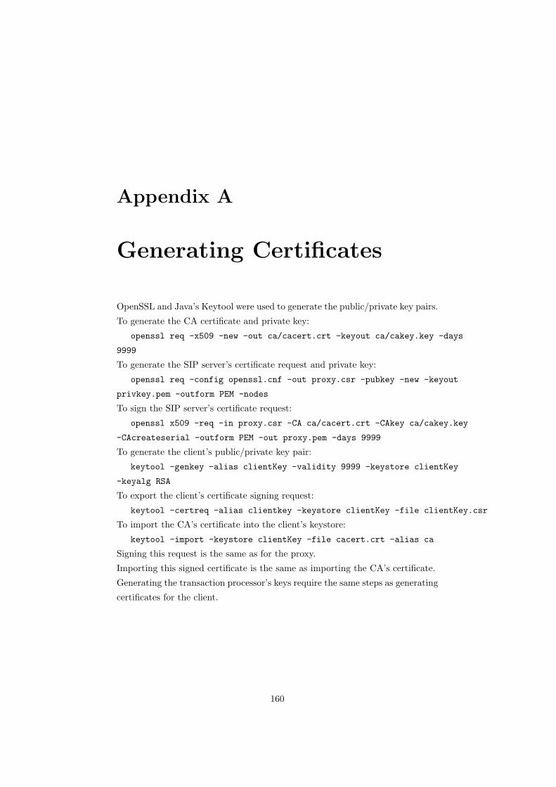
Appendix A
Generating Certificates
OpenSSL and Java’s Keytool were used to generate the public/private key pairs.
To generate the CA certificate and private key:
openssl req -x509 -new -out ca/cacert.crt -keyout ca/cakey.key -days
9999
To generate the SIP server’s certificate request and private key:
openssl req -config openssl.cnf -out proxy.csr -pubkey -new -keyout
privkey.pem -outform PEM -nodes
To sign the SIP server’s certificate request:
openssl x509 -req -in proxy.csr -CA ca/cacert.crt -CAkey ca/cakey.key
-CAcreateserial -outform PEM -out proxy.pem -days 9999
To generate the client’s public/private key pair:
keytool -genkey -alias clientKey -validity 9999 -keystore clientKey
-keyalg RSA
To export the client’s certificate signing request:
keytool -certreq -alias clientkey -keystore clientKey -file clientKey.csr
To import the CA’s certificate into the client’s keystore:
keytool -import -keystore clientKey -file cacert.crt -alias ca
Signing this request is the same as for the proxy.
Importing this signed certificate is the same as importing the CA’s certificate.
Generating the transaction processor’s keys require the same steps as generating
certificates for the client.
160
Top Related