


Languages
Pages
Legal


Vacío
RV
Bomba de vacío RV
Vacuum pump RV
2 3
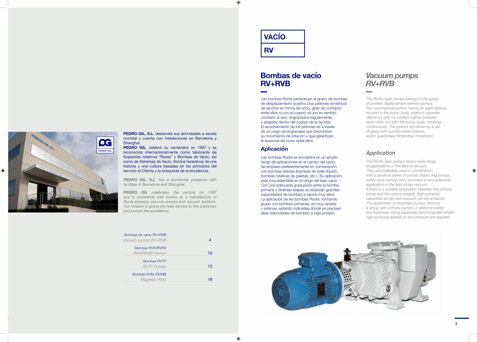
PEDRO GIL, S.L. desarrolla sus actividades a escala mundial y cuenta con instalaciones en Barcelona y Shanghai.PEDRO GIL, celebró su centenario en 1997 y es reconocida internacionalmente como fabricante de Soplantes rotativos “Roots” y Bombas de Vacío, así como de Sistemas de Vacío. Somos herederos de una historia y una cultura basadas en los principios del servicio al Cliente y la búsqueda de la excelencia.
PEDRO GIL, S.L. has a worldwide presence with facilities in Barcelona and Shanghai.
PEDRO GIL celebrates the century on 1997 and is worldwide well known as a manufacture of Roots blowers, vacuum pumps and vacuum systems.Our mission is giving the best service to the customer, and pursuit the excellence.
Bombas de vacío RV+RVBVacuum pumps RV+RVB
Bombas RVR/RVRB RVR/RVRB Pumps
Bombas RVTPRVTP Pumps
Bombas RVM /RVMB Magnetic RVM
4
10
15
18
VACÍO
RV
Bombas de vacío RV+RVB
Las bombas Roots pertenecen al grupo de bombas de desplazamiento positivo.Dos pistones simétricos de sección en forma de ocho, giran sin contacto entre ellos ni con el cuerpo: el uno en sentido contrario al otro, engranados regularmente, y alojados dentro del cuerpo de la bomba. El accionamiento de los pistones es a través de un juego de engranajes que sincronizan su movimiento de rotación y que garantizan la ausencia de roces entre ellos.
AplicaciónLas bombas Roots se encuentra en un amplio rango de aplicaciones en el campo del vacío. Se emplean preferentemente en combinación con bombas previas (bombas de anillo líquido, bombas rotativas de paletas, etc.). Su aplicación está muy extendida en el rango del bajo vacío. Con una adecuada graduación entre la bomba primaria y diversas etapas se alcanzan grandes capacidades de bombeo a vacíos muy altos. La aplicación de las bombas Roots, formando grupo con bombas primarias, es muy variada y extensa, estando indicadas donde se precisen altas velocidades de bombeo a baja presión.
The Roots-type pumps belong to the group of positive displacement delivery pumps. Two symmetrical pistons having an eight feature, housed in the pump body, rotate in opposite directions with no contact neither between each other nor with the pump body, meshing continuously. The pistons are driven by a set of gears with synchronised rotation, which guarantees frictionfree movement.
ApplicationThe Roots-type pumps have a wide range of applications in the field of vacuum. They are preferably used in combination with a previous series of pumps (liquid ring pumps, rotary vane pumps, etc.) and have a very extensive application in the field of low vacuum. If there is a suitable graduation between the primary pump and the various stages, high pumping capacities at very low vacuum can be achieved. The application of Rootstipe pumps, forming a group with primary pumps, is extremly varied and extensive, being especially recommended where high pumping speeds at low pressure are required.
Vacuum pumps RV+RVB

FORMAS CONSTRUCTIVAS
EJECUCIÓN A-2Visto de frente el eje de accionamiento
Sentido del gas: De izquierda a derecha.Posición del eje: AbajoSentido de giro: A la izquierda (antihorario)
EJECUCION B-4Visto de frente el eje de accionamiento
Sentido del gas: De arriba hacia abajo.Posición del eje: A la izquierdaSentido de giro: A la izquierda (antihorario)
NOTA: La ejecución normalizada es la B-4
CONSTRUCTION FORM
TYPE A-2From view of the drive shaft
Direction of gas: From left to right.Shaft position: BottomRotation direction: To the left (anticlockwise)
TYPE B-4From front view of the drive shaft
Direction of gas: From top to bottomShaft position: To the leftRotation position: To the left (anticlockwise)
NOTE: B-4 is the standard operation.
Principio de funcionamientoEn el curso de la rotación, se crea un espacio progresivamente creciente que corresponde a la fase de aspiración: fase 1 y 2, siendo progresivamente decreciente las fases 3 y 4, comprimiendo el volumen de gas. Este ciclo se repite cuatro veces por cada giro completo del eje de accionamiento.
Operating PrinciplesDuring rotation, a progressively growing space is created wich corresponds to the suction stage: phases 1 and 2, being gradually decreased phases 3 and 4, compressing the volume of gas. This cycle is repeated four times per each complete rotation of the drive shaft.
EJECUCIÓN A-2TYPE A-2
EJECUCION B-4TYPE B-4
4 5

RV + RVB
Características constructivas bombas RV+RVB
Las bombas del tipo RVB se emplean en combinación con bombas previas y eventualmente con condensadores montados en serie.
El eje de accionamiento de las bombas Roots es accionado directamente por el eje de motor por medio de un acoplamiento elástico. El paso del eje es sellado por medio de retenes con cámara de aceite como medio sellador. Incorpora una cámara de refrigeración al paso del eje para eliminar el calor producido por el cierre. Los retenes, así como el resto de elastómetros, son de material fluorelastometro VITON. El tipo RVB es suministrado con motor de bridas normalizadas de corriente alterna, trifásico y de acuerdo con normas IEC.
The RVB pumps are used in combination with a previous series of pumps and can also be used with condensers arranged in series connection.
The Roots-type pump drive shaft is directly driven by the motor shaft by means of an elastic coupling. The shaft passage is closed off by seals with an oil chamber, the oil being used as a sealing fluid. A cooling chamber is included for the shaft passage to eliminate the heat produced by the seal. The seals and the rest of the elastomers are made of VITON Fluorinated elastomer. The RVB type is supplied with an AC, three-phase motor and standardized flanges, in accordance with IEC standards.
Construction Characteristics RV+RVB Roots pumps
Caudal nominal de aspiración Rated suction flow
Velocidad de giro Rotation speed
Máx. diferencia de presión en contínuo Max. pressure difference with continuously
Potencia del motor Motor power
Tensión de red normal, 50 Hz Normal supply voltage, 50 Hz
Capacidad aceite en los carters A/B Oil Capacity in oil box A/B
Capacidad aceite cierre paso del eje Oil capacity shaft passage seal
Consumo agua de refrigeración Consumption cooling water
Peso bomba Roots con motor Weight Roots pump with motor
Peso bomba (eje libre) Weight of pump (free shaft)
Tamaño / Size 20.10 20.20 21.20 21.30 22.20 22.30 23.20 23.30
200
2850
130
0,8
230/400
0,7/1,1
0,06
60
73
62
280
2850
80
1,1
230/400
0,7/1,1
0,06
60
85
76
740
2860
80
3,0
230/400
1,22/1,75
0,07
80
158
135
500
2860
80
2,2
230/400
1,22/1,75
0,07
80
130
115
1000
2895
80
4,0
230/400
1,75/2,75
0,08
100
240
208
1430
2895
66
4,0
230/400
1,75/2,75
0,08
100
270
245
2000
2910
50
5,5
230/400
3,4/5,3
0,1
120
360
320
2880
2910
40
7,5
400
3,4/5,3
0,1
120
400
360
m3/h
min
mbar
kW
V
Ltr
Ltr
Ltr/h
kg
kg
Datos técnicos Technical data24.20 25.10 25.20 26.20 26.30 27.10 27.20
3725
2915
50
11,0
400
5,5/9,4
0,15
140
580
460
3725
2915
50
11,0
400
5,5/9,4
0,15
140
580
460
7954
1460
50
22,0
400
18/30
0,25
180
1600
1450
7295
2930
50
18,5
400
8,3/15,8
0,2
160
850
710
9470
1460
40
22,0
400
18/30
0,25
180
1700
1550
11515
1465
40
30,0
400
30/38
0,3
200
2490
2250
15558
1465
30
30,0
400
30/38
0,3
200
2690
2450
6 7

Dimensiones RV+RVBRV+RVB dimensions
c3b3
a3d1
RV
TIPO / TYPE B
RVB
TIPO / TYPE A
RV + RVB
h3
h1
c1
h
h2
h
b1
a
DN
DN
a2
l
a1
d
a6
u
c3b3
a3d1
RV
TIPO / TYPE B
RVB
TIPO / TYPE A
RV + RVB
h3
h1
c1
h
h2
h
b1
a
DN
DN
a2
l
a1
d
a6
u
c3b3
a3d1
RV
TIPO / TYPE B
RVB
TIPO / TYPE A
RV + RVB
h3
h1
c1
h
h2
h
b1
a
DN
DN
a2
l
a1
d
a6
u
c3b3
a3d1
RV
TIPO / TYPE B
RVB
TIPO / TYPE A
RV + RVB
h3
h1
c1
h
h2
h
b1
a
DN
DN
a2
l
a1
d
a6
u
Bridas / FlangesDIN2532 / PN10Tol ±2 mm
8 9
RVB RV
Tamaño Size a3a2a1aDN
50
80
100
100
100
150
150
150
200
200
250
300
300
300
350
b1 b2 c1 c3
20.1020.2021.2021.3022.2022.3023.2023.3024.2025.1025.2026.2026.3027.1027.20
a4
767
807
958
1103
1134
1246
1286
1445
1622
1599
1762
2088
2220
2300
2524
220
240
291
341
345
401
398
468
470
468
532
665
732
717
829
148
188
270
370
327
439
412
552
363
329
458
620
750
575
799
118
158
230
330
282
394
362
502
288
249
378
510
640
450
674
470
509
615
715
731
843
832
972
993
962
1091
1381
1512
1528
1753
313
313
366
366
426
426
534
534
592
728
728
948
948
1147
1147
253
253
290
290
354
354
444
444
528
638
638
848
848
1057
1057
240
240
281
281
313
313
388
388
420
514
514
666
666
812
812
178
178
204
204
240
240
298
298
356
424
424
566
566
722
722
h1h
14
14
18
18
18
18
24
24
24
24
24
24
24
27
27
h2 h3
Extremo eje Shaft’s end
d l u276
276
320
320
350
350
400
400
500
630
630
780
780
1000
1000
d1
340
340
353
382
417
417
494
494
602
743
743
925
925
1151
1151
138
138
160
160
175
175
200
200
250
315
315
390
390
500
500
176
176
203
203
232
232
271
271
335
421
421
525
525
668
668
20k6
20k6
28k6
28k6
32k6
32k6
38k6
38k6
42k6
42m6
42m6
75m6
75m6
90m6
90m6
45
45
53
53
68
68
68
68
88
86
86
106
106
190
190
6
6
8
8
10
10
10
10
12
16
16
20
20
25
25

RVR/RVRB
BY PASS
Seguridad en paradasy arrancadas frecuentes
La bomba de vacío con recirculación RVR está especialmente diseñada para aplicaciones en las que se requiere romper el vacío constantemente, por ejemplo envasado alimenticio al vacío. Para proteger la bomba de estas condiciones de trabajo, se ha dotado del conducto by-pass de recirculación regulado por válvula de sobrepresión. Esta bomba es muy adecuada en las aplicaciones en las que no es posible utilizar variador de frecuencia debido a que los constantes cambios, en lascondiciones de trabajo, acaban por deteriorar el motor eléctrico. Debido a que la bomba está dotada del by-pass es posible arrancar simultáneamente la bomba roots y la bomba previa, pues la máquina puede trabajar temporalmente sin un elevado vacío previo. Es conveniente no trabajar en un rango de presiones que provoquen la apertura permanente del conducto by-pass, porque el gas se calentaría continuamente hasta alcanzar el límite térmico de la máquina.
BOMBAS ROOTS TIPO RVR: Características constructivasLas mismas que el tipo RVRB con la variante que se suministra sin el soporte fijación del motor, sin el acoplamiento elástico y sin el motor. En definitiva el suministro es con eje libre.
The RVR vacuum pump with recirculation is especially designed for applications in wich the vacuum needs to be interrupted constantly, for instance, vacuum packaging of food. In order to protect the pump from these working conditions, it is provided with the recirculation by-pass conduit, regulated by a relief valve. This pump is very well suited for applications in which a frequency shifter cannot be used due to the fact that constant changes in the working conditions end up damaging the electrical motor. Since this pump is provided with the by-pass, it is possible to simultaneously start the Roots pump and the former pump, because the machine is able to work temporarily without a prior high vacuum. It is advisable not to work within a range of pressures that can result in permanent opening of the by-pass conduit, sinse the gas will continue to heat up until it reaches the thermal limit of the machine.
ROOTS PUMPS: RVR TYPE Manufacturing characteristicsThe same as the RVRB type, with the difference that the motor mounting support is supplied without the compensating coupling and without the motor. In short, it is supplied with is shaft free.
General details on the roots-type vacuum pumps
10 11
Materiales de construcción Manufacturing Materials
Cuerpo Cylinder
By-pass
Laterales intermedios Intermediate headplates
Cárters Oil sumps
Pistón - Eje Piston - Shaft
Engranajes Gears
Fundición GG-25 Cast iron GG-25
Acero forjado CK-45 Forged steel CK-45
Acero Din 18 Cr Mo 4 Steel Din 18 Cr Mo 4
Caudal nominal de aspiraciónRated suction flow
Velocidad de giro Rotation speed
Máxima diferencia de presión en funcionamiento contínuoMaximum pressure difference with continuous operation
Potencia del motor Motor power
Tensión de red normal, 50 Hz Normal supply voltage, 50 Hz
Capacidad aceite en los carters A/B Oil Capacity in oil box A/B
Capacidad aceite cierre paso del eje Oil capacity shaft passage seal
Consumo agua de refrigeración Consumption cooling water
Peso bomba Roots con motor Weight Roots pump with motor
Peso bomba (eje libre) Weight of pump (free shaft)
Tamaño / Size 21.20 22.20 23.20
m3/h
min
mbar
kW
V
Ltr
Ltr
Ltr/h
kg
kg
500
2860
50
2,2
230/400
1,22/1,75
0.07
80
156
141
1000
2895
50
4
230/400
1,75/2,75
0.08
100
260
228
2000
2910
50
5,5
230/400
3,4/5,3
0.1
120
402
360
Válvula de sobrepresión cerradaRelief valve closed
Válvula de sobrepresión abiertaRelief valve open

Datos técnicos Technical data
12 13
Bridas / FlangesDIN 2532/PN10
Tol ±2 mmRVR RVRB
Dimensiones Bombas RVR / RVRBDimensiones RVR / RVRB Pumps
d1h h2b2b1a3a2a1aPeso
WeightKgDNTam. motor
Size motorPmax.kW
nv/min.
Pmax.mbar
TamañoSize
90L
100L
100L
112
132 S
132 S
112
132 S
132 S
160 M
160 M
160 L
932
984
1109
1130
1181
1217
1268
1390
1471
1181
2.2
3
3
4
5.5
7.5
4
5.5
7.5
11
15
18.5
156
160
254
260
270
274
392
402
406
437
470
565
18160291
345 175
200398
2903000
3000 354
444
350
4103000
36650
50 426
53450
320270 23010021.20
10022.20 327 282
412 362
18
2415023.20

RVTP
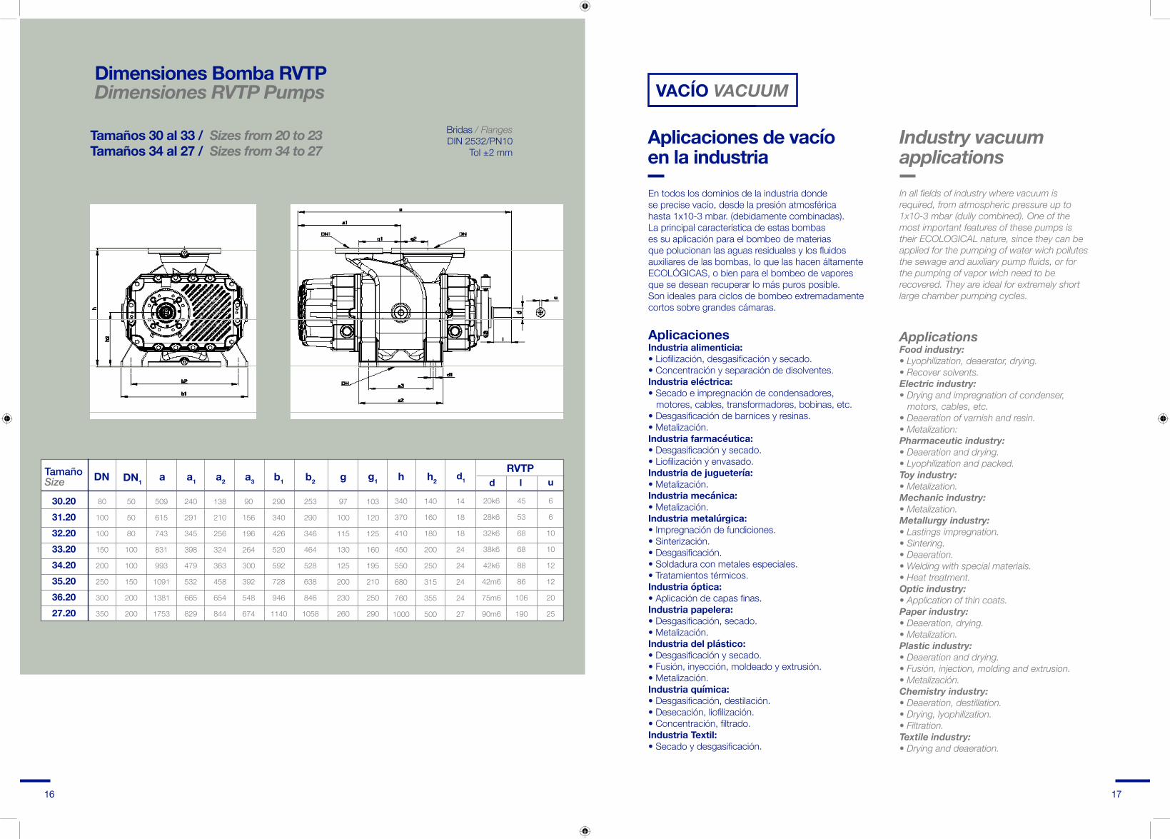
Bombas roots tipo RVTP TRILOBULARESSe fabrican ocho tamaños de bombas de pistones rotativos con preadmisión, para caudales nominales de 200 hasta 10.000 m3/h.
Características constructivasBomba diseñada para ser accionada preferentemente por acoplamiento elástico, si bien puede ser accionada por correas y poleas tomando las debidas precauciones de no sobrecargar el eje de accionamiento. El paso del eje es sellado por medio de retenes con cámara de aceite como medio sellador. Incorpora una cámara de refrigeración al paso del eje para eliminar el calor producido por el cierre. Los retenes son de material fluorelastomero VITON. Precisa siempre una bomba previa.
Eight sizes of previous intake rotary piston pumps are manufactured for rated flows from 200 to 10.000 m3/h.
Construction characteristicsPump designed to be driven preferably by elastic coupling, although it may use belt and pulley drive if due precautions are taken to avoid overloading the drive shaft. The shift passage is closed by seals with an oil chamber, the oil acting as a sealing fluid. A cooling chamber is included for the shaft passage to eliminate the heat produced by the seal. The seals are made of VITON Fluorinated elastomer. Always requires a previous pump.
Roots pumps RVTP THREE-LOBED type
Datos técnicos Technical data
Caudal nominal de aspirado Rated suction flow
Velocidad de giro Rotation speed
Presión diferencial máx. admisible (con acoplamiento directo)Maximum permitted differential pressure
Potencia máxima del motor Maximum motor power
Capacidad aceite en los carters Oil capacity in oil box
Capacidad aceite cierre paso del eje Oil capacity shaft passage seal
Consumo agua de refrigeración Consumption cooling water
Peso bomba (eje libre) Weight of pump (free shaft)
Tamaño / Size 30.20 31.20 32.20 33.20 34.20 35.20 36.20 27.20
RVTP
280
3000
400
4.0
0,7/1,10.066091
500
3000
400
7.5
1,22/1,750.0780127
1000
3000
400
15.0
1,75/2,750.08100215
2000
3000
300
30.0
3,4/5,30.1120335
3000
2200
300
37.0
5,5/9,40.15120455
4000
1800
300
55.0
8,3/13,80.2140682
8000
1500
300
90.0
18/300.251601385
10000
1000
300
132.0
30/380.31802450
m3/h
min
mbar
kW
Ltr
Ltr
Ltr/h
kg
PRINCIPALES VENTAJAS DE LOS TIPOS RVTP
- Compresión exenta de aceite (funcionamiento seco)- Presión diferencial Hasta 400 mbar. (tipo RVTP).- Altísima capacidad de aspiración- Zona de utilización de vacío total- Construcción compacta y robusta.- Funcionamiento sin vibraciones ni pulsaciones.- Bomba ecológica, puesto que al no precisar líquido de cierre, no contamina.
MAIN ADVANTAGES OF TYPES RVTP
- Oil-free compression. (dry operating).- Differentialpressure. Up to 400 mbar (RVTP type).- Extremly high suction capacity.- Total vacuum area use.- Compact, sturdy structure.- Vibration and pulsation-free operating.- Ecological pump, non-contaminating as no sealing liquid is required.
14 15
VACÍO VACUUM
Aplicaciones de vacíoen la industriaEn todos los dominios de la industria donde se precise vacío, desde la presión atmosférica hasta 1x10⁻³ mbar. (debidamente combinadas). La principal característica de estas bombas es su aplicación para el bombeo de materias que polucionan las aguas residuales y los fluidos auxiliares de las bombas, lo que las hacen áltamente ECOLÓGICAS, o bien para el bombeo de vapores que se desean recuperar lo más puros posible. Son ideales para ciclos de bombeo extremadamente cortos sobre grandes cámaras.
In all fields of industry where vacuum is required, from atmospheric pressure up to 1x10⁻³ mbar (dully combined). One of the most important features of these pumps is their ECOLOGICAL nature, since they can be applied for the pumping of water wich pollutes the sewage and auxiliary pump fluids, or for the pumping of vapor wich need to be recovered. They are ideal for extremely short large chamber pumping cycles.
Industry vacuumapplications
AplicacionesIndustria alimenticia:• Liofilización, desgasificación y secado.• Concentración y separación de disolventes.Industria eléctrica:• Secado e impregnación de condensadores, motores, cables, transformadores, bobinas, etc.• Desgasificación de barnices y resinas.• Metalización.Industria farmacéutica:• Desgasificación y secado.• Liofilización y envasado.Industria de juguetería:• Metalización.Industria mecánica:• Metalización.Industria metalúrgica:• Impregnación de fundiciones.• Sinterización.• Desgasificación.• Soldadura con metales especiales.• Tratamientos térmicos.Industria óptica:• Aplicación de capas finas.Industria papelera:• Desgasificación, secado.• Metalización.Industria del plástico:• Desgasificación y secado.• Fusión, inyección, moldeado y extrusión.• Metalización.Industria química:• Desgasificación, destilación.• Desecación, liofilización.• Concentración, filtrado.Industria Textil:• Secado y desgasificación.
ApplicationsFood industry:• Lyophilization, deaerator, drying.• Recover solvents.Electric industry:• Drying and impregnation of condenser, motors, cables, etc.• Deaeration of varnish and resin.• Metalization:Pharmaceutic industry:• Deaeration and drying.• Lyophilization and packed.Toy industry:• Metalization.Mechanic industry:• Metalization.Metallurgy industry:• Lastings impregnation.• Sintering.• Deaeration.• Welding with special materials.• Heat treatment.Optic industry:• Application of thin coats.Paper industry:• Deaeration, drying.• Metalization.Plastic industry:• Deaeration and drying.• Fusión, injection, molding and extrusion.• Metalización.Chemistry industry:• Deaeration, destillation.• Drying, lyophilization.• Filtration.Textile industry:• Drying and deaeration.
TamañoSize a3a2a1aDN
80
100
100
150
200
250
300
350
50
50
80
100
100
150
200
200
240
291
345
398
479
532
665
829
90
156
196
264
300
392
548
674
290
340
426
520
592
728
946
1140
253
290
346
464
528
638
846
1058
97
100
115
130
125
200
230
260
509
615
743
831
993
1091
1381
1753
138
210
256
324
363
458
654
844
103
120
125
160
195
210
250
290
b1
30.2031.2032.2033.2034.2035.2036.2027.20
b2DN1 g g1 h
340
370
410
450
550
680
760
1000
h2 d l ud1
RVTP
140
160
180
200
250
315
355
500
14
18
18
24
24
24
24
27
20k6
28k6
32k6
38k6
42k6
42m6
75m6
90m6
45
53
68
68
88
86
106
190
6
6
10
10
12
12
20
25
Tamaños 30 al 33 / Sizes from 20 to 23Tamaños 34 al 27 / Sizes from 34 to 27
16 17
Dimensiones Bomba RVTPDimensiones RVTP Pumps
Bridas / FlangesDIN 2532/PN10
Tol ±2 mm
18 19
RVM
MAGNÉTICO
Altas prestaciones Acoplamiento magnético del ejeMayor rendimiento en alto vacíoMejor estanqueidadBajo coeficiente de fugasHasta 10-5 mbarLarga vida del cierre
APLICACIONES APPLICATIONS
Magnetic coupling on the saftBetter efficiency in high vacuumBetter sealing with a life increaseLow leakage coefficient
La constante investigación del Departamento de I+D+I de Pedro Gil y la experiencia de más de 40 años en la fabricación de bombas de vacío Roots, nos ha llevado a obtener una de las mejoras más importantes de los últimos tiempos.
La eliminación del cierre dinámico del eje y su sustitución por el acoplamiento magnético, con el que se consigue un cierre estático de mejor estanqueidad y que alarga la vida de la bomba de forma notable.
Las bombas de vacío Roots RVM accionadas mediante acoplamiento magnético, proporcionan amplias ventajas sobre las bombas convencionales, el coeficiente de fugas es mucho menor, con lo que el vacío final de trabajo puede llegar hasta 10-5 mbar, proporcionando un rendimiento mucho mayor en la zona de alto vacío.
La estanqueidad de la cámara de compresión se realiza mediante segmentos de cierre, o cierres específicos para aplicaciones concretas.
Industria semiconductoresMicro electrónicaTecnología láserTecnología solarMetalizadorasIndustria envasado vacíoProcesos industria químicaProcesos industria farmacéutica
Semiconductor industryMicroelectronicsLaser technologySolar technologyMetalisersVacuum packing industryChemical process industryPhamaceutical process industry
Pedro Gil’s R&D&I Department continuous research, combined with more than 40 years company’s experience manufacturing Roots vacuum pumps, let us achieve one of the most important improvements in recent years.
Dynamical sealing has been replaced by the new magnetic coupling obtaining a better leak proof with a static sealing increasing pump life.
Roots RVM vacuum pumps driven with magnetic coupling provide extensive advantatges over conventional pumps.
Leaking the coefficient is much lower reaching a final vacuum up to 10-5 mbar, providing better efficiency in high vacuum range. Compressions chamber’s sealing is achieved weather by seal segments or by specific seals for concrete applications.
High perfomanceTodo son ventajasCon el acoplamiento magnético se consigue:
OfferingmorebenefitsWith magnetic seals,we achieve:
Velocidades de bombeo desde 100 hasta 15.500 m3/h
Aumento significativo del rendimiento de la bomba
Rango de presiones de 10-2 hasta 10-5 mbar
Sin mantenimiento, ausencia de retenes en el eje por el acoplamiento magnético.
Ausencia de agua de refrigeración
Apropiada para trabajo en aplicaciones de salas limpias
Posibilidad de acoplar cualquier tipo de motor con brida
Apta para trabajar con variador de frecuencia, lo que permite aumentos de velocidad hasta un 50% puntualmente
También disponible con válvula de sobre presión
Dirección del fluido horizontal o vertical disponible
Bombas con certificado Atex
Vacuum pump capacity from 100 up to 15.000 m3/h
Increase pump efficiency
Pressure range from 10-2 up to 10-5 mbar
Maintenance free
Refrigeration water free
Suitable for use in “clean room” applications
Any type of motor with flange can be adapted
Suitable for working with frequency converters enabling speed increases up to 50% intermittenly
Overpressure valve version is also available
Fluid direction can be horitzontal or vertical
Pumps with Atex certificate
RVM
MAGNÉTICO
1234
5678
91011
12345678
91011

20 21
Datos técnicosTechnical dataCaudalFlow m3/hVelocidad giroTurning speed r.p.mMáx. Dif. Presión funcio.ContMax. Pressure Diff. Cont mbarPotencia motorMotor power KwCapacidad aceite cartersOil capacity LtPeso de la bomba con motorWeight of pump - with motor KgPeso de la bomba eje libreWeight of pump - free shaft Kg
50 Hz
200
2850
80
0,75
1
75
65
50 Hz
280
2850
80
1,1
1
85
76
50 Hz
500
2850
80
2,2
1,6
130
115
50 Hz
750
2850
80
3
1,6
165
135
50 Hz
1000
2850
80
4
2,5
240
210
50 Hz
1450
2850
66
4
2,5
270
245
50 Hz
2000
2850
50
5,5
4,8
360
320
50 Hz
2900
2850
40
7,5
4,8
400
360
50 Hz
3725
2915
50
11
8,5
580
460
50 Hz
8000
1460
50
22
17
1600
1450
50 Hz
9500
1460
40
22
17
1700
1550
50 Hz
5500
2915
66
15
12,5
755
630
50 Hz
7300
2915
50
18,5
12,5
850
710
60 Hz
280
3600
80
1,1
1
78
65
60 Hz
334
3600
80
1,5
1
87
76
60 Hz
600
3600
80
3
1,6
135
115
60 Hz
950
3600
80
4
1,6
165
135
60 Hz
1200
3600
80
4
2,5
240
210
60 Hz
1720
3600
66
5,5
2,5
290
245
60 Hz
2450
3600
50
7,5
4,8
375
320
60 Hz
3500
3600
40
11
4,8
420
360
60 Hz
4600
3600
50
15
8,5
600
460
60 Hz
9800
1800
50
22
17
1600
1450
60 Hz
13000
1200
40
30
17
1800
1550
máx.vel
350
5000
50
1,5
1
82
65
máx.vel
465
5000
50
2,2
1
130
115
máx.vel
830
5000
50
3
1,6
135
115
máx.vel
1300
5000
50
4
1,6
185
135
máx.vel
1750
5000
50
4
2,5
240
210
máx.vel
1920
4000
50
5,5
2,5
290
245
máx.vel
2720
4000
50
7,5
4,8
375
320
máx.vel
3500
3600
40
11
4,8
420
360
máx.vel
4600
3600
50
15
8,5
600
460
máx.vel
10900
2000
50
22
17
1600
1450
máx.vel
16000
2000
40
30
17
1800
1550
20.10 20.20 21.20 21.30 22.20 22.30 23.20 23.30 24.20 26.20 26.3024.20 25.20máx.vel
5500
2915
66
15
12,5
755
630
máx.vel
7300
2915
50
18,5
12,5
850
710
Vacuum pump shaft
Electrical motor shaft
Inner magnet
O-ringOuter magnet
Vacuum
Curva acoplamiento magnético Magnetic coupling curveCurva acoplamiento convencional Conventional coupling curve
El acoplamiento magnético en el banco de pruebas, en las instalaciones PG
Magnetic coupling on the testing bench at PG’s facilities

a3
d1
c2
b2h1
h3
h
c1
DN
a2
a
a1
TIPO / TYPE A
RVMBTIPO / TYPE B
DNh
h2
b1
a3
d1
c2
b2
h1
h3
h
c1
DN
a2
a
a1
TIPO / TYPE A
RVMBTIPO / TYPE B
DN
h
h2
b1
a3
d1
c2
b2
h1
h3
h
c1
DN
a2
a
a1
TIPO / TYPE A
RVMBTIPO / TYPE B
DN
h
h2
b1
22 23
Posar una foto RVMB
Dimensiones RVMBRVMB dimensions
Tipo Type B Tipo Type A
TamañoSize b2
253
253
290
290
354
354
444
444
528
638
638
848
848
b1
313
313
366
366
426
426
534
534
592
728
728
948
948
a3
118
158
230
330
282
394
362
502
288
249
378
510
640
a2
148
188
270
370
327
439
412
552
363
329
458
620
750
a1
220
240
291
341
345
401
398
468
470
468
532
665
732
a
767
807
958
1103
1134
1246
1286
1445
1622
1599
1762
2088
2220
DN
50
80
100
100
100
150
150
150
200
200
250
300
300
240
240
281
281
313
313
388
388
420
514
514
666
666
c1
178
178
204
204
240
240
298
298
356
424
424
566
566
c2
276
276
320
320
350
350
400
400
500
630
630
780
780
h
340
340
353
382
417
417
494
494
602
743
743
925
925
h1
138
138
160
160
175
175
200
200
250
315
315
390
390
h2
176
176
203
203
232
232
271
271
335
421
421
525
525
h3
20.1020.2021.2021.3022.2022.3023.2023.3024.2025.1025.2026.2026.30
Bridas / FlangesDIN 2532/PN10 ATol ±2 mm

Salvador Albert i Riera, 9 · Pol. Ind. Vallmorena · 08339 Vilassar de Dalt · Barcelona · EspañaTel: +34 93 753 71 71 · Fax: +34 93 753 73 00 · E-mail: [email protected] · www.pedrogil.com
Top Related