


Languages
Pages
Legal

BNT Layer 2/3 Copper and Fiber Gigabit Ethernet Switch Modules for IBM BladeCenter 1
��� ®
BNT Layer 2/3 Copper and Fiber Gigabit Ethernet Switch Modules for IBM BladeCenterIBM BladeCenter at-a-glance guide
As business applications become more and more demanding, data centers have become more complex, cumbersome, and expensive to manage. IBM BladeCenter offers solutions to help lower costs while enhancing performance by accommodating many integration technologies.
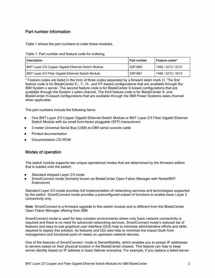
The BNT Layer 2/3 Switch offers all the switching features in a BladeCenter chassis at a competitive price. This switch is offered in two versions: Copper and Fiber. These versions provide reliability and flexibility and meet all the stringent requirements of both enterprise and telecom environments. Figure 1 shows the two switch modules.
Figure 1. BNT Layer 2/3 Copper (left) and Fiber (right) Gigabit Ethernet Switch Modules
Did you know?
Clients do not need the most expensive switches to manage their virtualization requirements. These low cost switches offer the maximum uplink bandwidth and a low blocking ratio for maximum performance, while consuming extremely lower power at only 27W. The fiber model is ideal for those who need to carry data greater distances, want better security since it is difficult to tap and does not radiate data, or look for better reliability because it is immune to electromagnetic interference.
BNT Layer 2/3 Copper and Fiber Gigabit Ethernet Switch Modules for IBM BladeCenter 2
Part number information
Table 1 shows the part numbers to order these modules.
Table 1. Part number and feature code for ordering
Description Part number Feature codes*
BNT Layer 2/3 Copper Gigabit Ethernet Switch Module 32R1860 1495 / 3212 / 3212
BNT Layer 2/3 Fiber Gigabit Ethernet Switch Module 32R1861 1496 / 3213 / 3213
* Feature codes are listed in the form of three codes separated by a forward slash mark (/). The first feature code is for BladeCenter E-, T-, H-, and HT-based configurations that are available through the IBM System x server. The second feature code is for BladeCenter S-based configurations that are available through the System x sales channel. The third feature code is for BladeCenter S- and BladeCenter H-based configurations that are available through the IBM Power Systems sales channel when applicable.
The part numbers include the following items:
One BNT Layer 2/3 Copper Gigabit Ethernet Switch Module or BNT Layer 2/3 Fiber Gigabit Ethernet Switch Module with six small form-factor pluggable (SFP) transceivers
3-meter Universal Serial Bus (USB)-to-DB9 serial console cable
Printed documentation
Documentation CD-ROM
Modes of operation
The switch module supports two unique operational modes that are determined by the firmware edition that is loaded onto the switch:
Standard shipped Layer 2/3 modeSmartConnect mode (formerly known as BladeCenter Open Fabric Manager with Nortel/BNT Extensions)
Standard Layer 2/3 mode provides full implementation of networking services and technologies supported by the switch. SmartConnect mode provides a preconfigured subset of functions to enable basic Layer 2 connectivity only.
Note: SmartConnect is a firmware upgrade to this switch module and is different from the BladeCenter Open Fabric Manager offering from IBM.
SmartConnect mode is used for less complex environments where only basic network connectivity is required and there is no need for advanced networking services. SmartConnect mode’s reduced set of features and easy-to-use graphical user interface (GUI) help to minimize administrative efforts and skills required to deploy this solution. Its features and GUI also help to minimize the impact (both from management and functional point of views) on upstream network devices.
One of the features of SmartConnect mode is ServerMobility, which enables you to assign IP addresses to servers based on their physical location in the BladeCenter chassis. This feature can help to keep server identity based on IP address in basic failover scenarios. For example, if you replace a failed server
BNT Layer 2/3 Copper and Fiber Gigabit Ethernet Switch Modules for IBM BladeCenter 3
with a new unit, this new unit will have the same IP address as the failed server. Alternatively, if the serverfails, then the other server in the chassis gets the IP address of the failed server. A Dynamic Host Configuration Protocol (DHCP) server is required for ServerMobility operations.
Specifically, the following functions are supported in SmartConnect mode:
Port groupsVirtual LAN (VLAN) and VLAN taggingTrunking (link aggregation)Layer 2 Failover (Switch Failover)IGMP snoopingWeb-based or command-line interface (CLI)-based management interfaceSupport for SSHRADIUS/TACACS+ access control to the switchPort monitoringServerMobility
Notes:
When the switch operates in SmartConnect mode, do not connect the host devices, such as workstations or servers, to the external ports because this leads to problems with network traffic flow.
The Spanning Tree Protocol (STP) is not supported in SmartConnect mode. By using the color-based BNT configuration tool, it is simple to build a loop-free layer 2 topology. The software also avoids basic mistakes that lead to these events .
Benefits
The BNT Layer 2/3 Copper and Fiber Gigabit Ethernet Switch Modules offer the following benefits:
Integration and consolidation : These modules offer integration within the BladeCenter chassis, enabling clients to consolidate full Layer 2-3 LAN switching and routing capabilities into a single chassis. This consolidation helps flatten the data center infrastructure and reduces the number of discrete devices, management consoles, and equipment that administrators must deal with, helping to lower costs and simplify deployment.
Layer 3 functionality: The BNT Layer 2/3 Copper and Fiber Gigabit Ethernet Switch Modules are two of only a few switch modules in the blade market that include Layer 3 functionality as standard, which provides security and performance benefits as inter-VLAN traffic stays within the chassis. These switches also provide the full range of industry-standard Layer 3 protocols from static routes for small and medium business (SMB) customers to technologies, such as Open Shortest Path First (OSPF) and Border Gateway Protocol (BGP), for enterprise customers.
Fiber offering: The fiber switch module is ideal for those clients who require fiber for high data rate systems that demand high bandwidth over long distances and require complete immunity to electrical interference.
Interoperability: BNT switches interoperate seamlessly with the upstream switches of other vendors.
Management: These switches are designed to support multiple CLIs, which allows IT staff to select one with which they are most comfortable: BLADEOS CLI for those who have a Nortel switch background, industry based CLI (Cisco-like) for those who are familiar with IOS, and a full-function Web-based GUI for the latest in simplicity.
Fault tolerance: These BNT switches automatically learn alternate routes and perform faster convergence in the unlikely case of a link, switch, or power failure. The switch uses proven technologies such as L2 trunk failover, advanced VLAN-based failover, Virtual Router Redundancy Protocol (VRRP), IGMP V3 snooping, and OSPF.
BNT Layer 2/3 Copper and Fiber Gigabit Ethernet Switch Modules for IBM BladeCenter 4
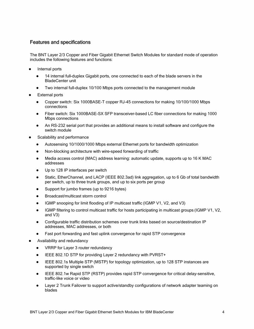
Features and specifications
The BNT Layer 2/3 Copper and Fiber Gigabit Ethernet Switch Modules for standard mode of operation includes the following features and functions:
Internal ports
14 internal full-duplex Gigabit ports, one connected to each of the blade servers in the BladeCenter unit
Two internal full-duplex 10/100 Mbps ports connected to the management module
External ports
Copper switch: Six 1000BASE-T copper RJ-45 connections for making 10/100/1000 Mbps connections
Fiber switch: Six 1000BASE-SX SFP transceiver-based LC fiber connections for making 1000 Mbps connections
An RS-232 serial port that provides an additional means to install software and configure the switch module
Scalability and performance
Autosensing 10/1000/1000 Mbps external Ethernet ports for bandwidth optimization
Non-blocking architecture with wire-speed forwarding of traffic
Media access control (MAC) address learning: automatic update, supports up to 16 K MAC addresses
Up to 128 IP interfaces per switch
Static, EtherChannel, and LACP (IEEE 802.3ad) link aggregation, up to 6 Gb of total bandwidth per switch, up to three trunk groups, and up to six ports per group
Support for jumbo frames (up to 9216 bytes)
Broadcast/multicast storm control
IGMP snooping for limit flooding of IP multicast traffic (IGMP V1, V2, and V3)
IGMP filtering to control multicast traffic for hosts participating in multicast groups (IGMP V1, V2, and V3)
Configurable traffic distribution schemes over trunk links based on source/destination IP addresses, MAC addresses, or both
Fast port forwarding and fast uplink convergence for rapid STP convergence
Availability and redundancy
VRRP for Layer 3 router redundancy
IEEE 802.1D STP for providing Layer 2 redundancy with PVRST+
IEEE 802.1s Multiple STP (MSTP) for topology optimization, up to 128 STP instances are supported by single switch
IEEE 802.1w Rapid STP (RSTP) provides rapid STP convergence for critical delay-sensitive, traffic-like voice or video
Layer 2 Trunk Failover to support active/standby configurations of network adapter teaming on blades
BNT Layer 2/3 Copper and Fiber Gigabit Ethernet Switch Modules for IBM BladeCenter 5
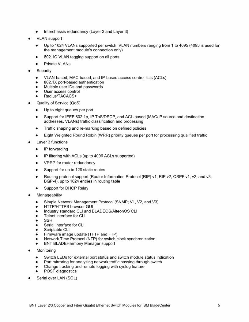
Interchassis redundancy (Layer 2 and Layer 3)
VLAN support
Up to 1024 VLANs supported per switch; VLAN numbers ranging from 1 to 4095 (4095 is used for the management module’s connection only)
802.1Q VLAN tagging support on all ports
Private VLANs
Security
VLAN-based, MAC-based, and IP-based access control lists (ACLs)802.1X port-based authenticationMultiple user IDs and passwordsUser access controlRadius/TACACS+
Quality of Service (QoS)
Up to eight queues per port
Support for IEEE 802.1p, IP ToS/DSCP, and ACL-based (MAC/IP source and destination addresses, VLANs) traffic classification and processing
Traffic shaping and re-marking based on defined policies
Eight Weighted Round Robin (WRR) priority queues per port for processing qualified traffic
Layer 3 functions
IP forwarding
IP filtering with ACLs (up to 4096 ACLs supported)
VRRP for router redundancy
Support for up to 128 static routes
Routing protocol support (Router Information Protocol (RIP) v1, RIP v2, OSPF v1, v2, and v3, BGP-4), up to 1024 entries in routing table
Support for DHCP Relay
Manageability
Simple Network Management Protocol (SNMP; V1, V2, and V3)HTTP/HTTPS browser GUIIndustry standard CLI and BLADEOS/AlteonOS CLITelnet interface for CLISSHSerial interface for CLIScriptable CLIFirmware image update (TFTP and FTP)Network Time Protocol (NTP) for switch clock synchronizationBNT BLADEHarmony Manager support
Monitoring
Switch LEDs for external port status and switch module status indicationPort mirroring for analyzing network traffic passing through switchChange tracking and remote logging with syslog featurePOST diagnostics
Serial over LAN (SOL)
BNT Layer 2/3 Copper and Fiber Gigabit Ethernet Switch Modules for IBM BladeCenter 6
The switch module supports the following IEEE standards:
IEEE 802.1D STP with PVRST+IEEE 802.1s MSTPIEEE 802.1w RSTPIEEE 802.1p Tagged PacketsIEEE 802.1Q Tagged VLAN (frame tagging on all ports when VLANs are enabled)IEEE 802.1x port-based authenticationIEEE 802.2 Logical Link ControlIEEE 802.3ad Link Aggregation Control ProtocolIEEE 802.3x Full-duplex Flow ControlFor the copper switch module:
IEEE 802.3 10BASE-T EthernetIEEE 802.3u 100BASE-TX Fast EthernetIEEE 802.3ab 1000BASE-T Gigabit EthernetIEEE 802.3z 1000BASE-X Gigabit Ethernet
For the fiber switch module:IEEE 802.3z 1000BASE-X Gigabit Ethernet1000BASE-SX Gigabit Ethernet
Supported BladeCenter chassis and expansion cards
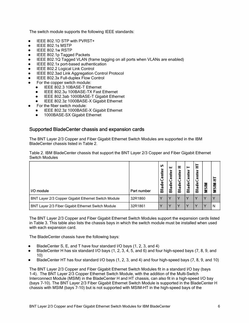
The BNT Layer 2/3 Copper and Fiber Gigabit Ethernet Switch Modules are supported in the IBM BladeCenter chassis listed in Table 2.
Table 2. IBM BladeCenter chassis that support the BNT Layer 2/3 Copper and Fiber Gigabit Ethernet Switch Modules
I/O module Part number
BNT Layer 2/3 Copper Gigabit Ethernet Switch Module 32R1860 Y Y Y Y Y Y Y
BNT Layer 2/3 Fiber Gigabit Ethernet Switch Module 32R1861 Y Y Y Y Y Y N
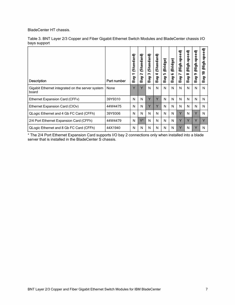
The BNT Layer 2/3 Copper and Fiber Gigabit Ethernet Switch Modules support the expansion cards listed in Table 3. This table also lists the chassis bays in which the switch module must be installed when used with each expansion card.
The BladeCenter chassis have the following bays:
BladeCenter S, E, and T have four standard I/O bays (1, 2, 3, and 4)BladeCenter H has six standard I/O bays (1, 2, 3, 4, 5, and 6) and four high-speed bays (7, 8, 9, and 10)BladeCenter HT has four standard I/O bays (1, 2, 3, and 4) and four high-speed bays (7, 8, 9, and 10)
The BNT Layer 2/3 Copper and Fiber Gigabit Ethernet Switch Modules fit in a standard I/O bay (bays 1-4). The BNT Layer 2/3 Copper Ethernet Switch Module, with the addition of the Multi-Switch Interconnect Module (MSIM) in the BladeCenter H and HT chassis, can also fit in a high-speed I/O bay (bays 7-10). The BNT Layer 2/3 Fiber Gigabit Ethernet Switch Module is supported in the BladeCenter H chassis with MSIM (bays 7-10) but is not supported with MSIM-HT in the high-speed bays of the
BNT Layer 2/3 Copper and Fiber Gigabit Ethernet Switch Modules for IBM BladeCenter 7
BladeCenter HT chassis.
Table 3. BNT Layer 2/3 Copper and Fiber Gigabit Ethernet Switch Modules and BladeCenter chassis I/O bays support
Description Part number
Gigabit Ethernet integrated on the server system board
None Y Y N N N N N N N N
Ethernet Expansion Card (CFFv) 39Y9310 N N Y Y N N N N N N
Ethernet Expansion Card (CIOv) 44W4475 N N Y Y N N N N N N
QLogic Ethernet and 4 Gb FC Card (CFFh) 39Y9306 N N N N N N Y N Y N
2/4 Port Ethernet Expansion Card (CFFh) 44W4479 N Y* N N N N Y Y Y Y
QLogic Ethernet and 8 Gb FC Card (CFFh) 44X1940 N N N N N N Y N Y N
* The 2/4 Port Ethernet Expansion Card supports I/O bay 2 connections only when installed into a blade server that is installed in the BladeCenter S chassis.
BNT Layer 2/3 Copper and Fiber Gigabit Ethernet Switch Modules for IBM BladeCenter 8
Popular configurations
The BNT Layer 2/3 Copper and Fiber Gigabit Ethernet Switch Modules can be used in various configurations.
Basic two-port configuration
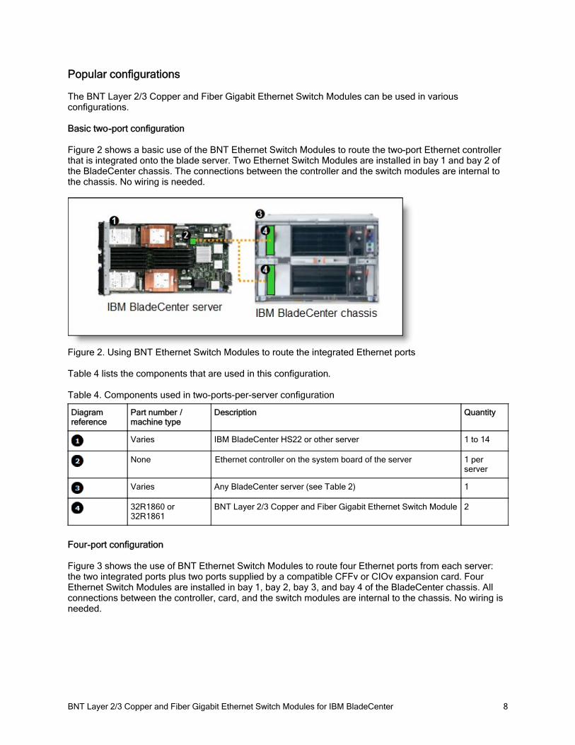
Figure 2 shows a basic use of the BNT Ethernet Switch Modules to route the two-port Ethernet controller that is integrated onto the blade server. Two Ethernet Switch Modules are installed in bay 1 and bay 2 of the BladeCenter chassis. The connections between the controller and the switch modules are internal to the chassis. No wiring is needed.
Figure 2. Using BNT Ethernet Switch Modules to route the integrated Ethernet ports
Table 4 lists the components that are used in this configuration.
Table 4. Components used in two-ports-per-server configuration
Diagram reference
Part number / machine type
Description Quantity
Varies IBM BladeCenter HS22 or other server 1 to 14
None Ethernet controller on the system board of the server 1 per server
Varies Any BladeCenter server (see Table 2) 1
32R1860 or 32R1861
BNT Layer 2/3 Copper and Fiber Gigabit Ethernet Switch Module 2
Four-port configuration
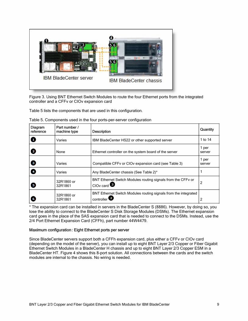
Figure 3 shows the use of BNT Ethernet Switch Modules to route four Ethernet ports from each server: the two integrated ports plus two ports supplied by a compatible CFFv or CIOv expansion card. Four Ethernet Switch Modules are installed in bay 1, bay 2, bay 3, and bay 4 of the BladeCenter chassis. All connections between the controller, card, and the switch modules are internal to the chassis. No wiring is needed.
BNT Layer 2/3 Copper and Fiber Gigabit Ethernet Switch Modules for IBM BladeCenter 9
Figure 3. Using BNT Ethernet Switch Modules to route the four Ethernet ports from the integrated controller and a CFFv or CIOv expansion card
Table 5 lists the components that are used in this configuration.
Table 5. Components used in the four ports-per-server configuration
Diagram reference
Part number / machine type Description Quantity
Varies IBM BladeCenter HS22 or other supported server 1 to 14
None Ethernet controller on the system board of the server1 per server
Varies Compatible CFFv or CIOv expansion card (see Table 3)1 per server
Varies Any BladeCenter chassis (See Table 2)* 1
32R1860 or 32R1861
BNT Ethernet Switch Modules routing signals from the CFFv or
CIOv card 2
32R1860 or 32R1861
BNT Ethernet Switch Modules routing signals from the integrated
controller 2
* The expansion card can be installed in servers in the BladeCenter S (8886). However, by doing so, you lose the ability to connect to the BladeCenter S Disk Storage Modules (DSMs). The Ethernet expansion card goes in the place of the SAS expansion card that is needed to connect to the DSMs. Instead, use the 2/4 Port Ethernet Expansion Card (CFFh), part number 44W4479.
Maximum configuration: Eight Ethernet ports per server
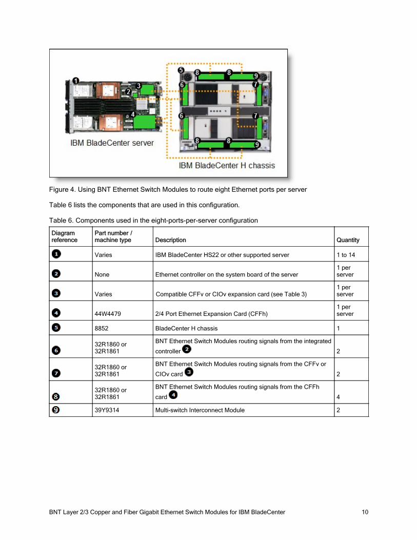
Since BladeCenter servers support both a CFFh expansion card, plus either a CFFv or CIOv card (depending on the model of the server), you can install up to eight BNT Layer 2/3 Copper or Fiber Gigabit Ethernet Switch Modules in a BladeCenter H chassis and up to eight BNT Layer 2/3 Copper ESM in a BladeCenter HT. Figure 4 shows this 8-port solution. All connections between the cards and the switch modules are internal to the chassis. No wiring is needed.
BNT Layer 2/3 Copper and Fiber Gigabit Ethernet Switch Modules for IBM BladeCenter 10
Figure 4. Using BNT Ethernet Switch Modules to route eight Ethernet ports per server
Table 6 lists the components that are used in this configuration.
Table 6. Components used in the eight-ports-per-server configuration
Diagram reference
Part number / machine type Description Quantity
Varies IBM BladeCenter HS22 or other supported server 1 to 14
None Ethernet controller on the system board of the server1 per server
Varies Compatible CFFv or CIOv expansion card (see Table 3)1 per server
44W4479 2/4 Port Ethernet Expansion Card (CFFh)1 per server
8852 BladeCenter H chassis 1
32R1860 or 32R1861
BNT Ethernet Switch Modules routing signals from the integrated
controller 2
32R1860 or 32R1861
BNT Ethernet Switch Modules routing signals from the CFFv or
CIOv card 2
32R1860 or 32R1861
BNT Ethernet Switch Modules routing signals from the CFFh
card 4
39Y9314 Multi-switch Interconnect Module 2
BNT Layer 2/3 Copper and Fiber Gigabit Ethernet Switch Modules for IBM BladeCenter 11
Connectors and LEDs
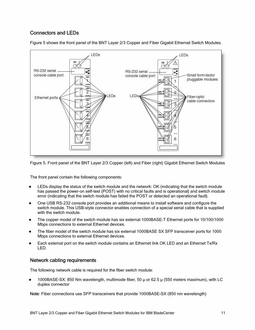
Figure 5 shows the front panel of the BNT Layer 2/3 Copper and Fiber Gigabit Ethernet Switch Modules.
Figure 5. Front panel of the BNT Layer 2/3 Copper (left) and Fiber (right) Gigabit Ethernet Switch Modules
The front panel contain the following components:
LEDs display the status of the switch module and the network: OK (indicating that the switch module has passed the power-on self-test (POST) with no critical faults and is operational) and switch module error (indicating that the switch module has failed the POST or detected an operational fault).
One USB RS-232 console port provides an additional means to install software and configure the switch module. This USB-style connector enables connection of a special serial cable that is supplied with the switch module.
The copper model of the switch module has six external 1000BASE-T Ethernet ports for 10/100/1000 Mbps connections to external Ethernet devices.
The fiber model of the switch module has six external 1000BASE SX SFP transceiver ports for 1000 Mbps connections to external Ethernet devices.
Each external port on the switch module contains an Ethernet link OK LED and an Ethernet Tx/Rx LED.
Network cabling requirements
The following network cable is required for the fiber switch module:
1000BASE-SX: 850 Nm wavelength, multimode fiber, 50 µ or 62.5 µ (550 meters maximum), with LC duplex connector
Note: Fiber connections use SFP transceivers that provide 1000BASE-SX (850 nm wavelength)
BNT Layer 2/3 Copper and Fiber Gigabit Ethernet Switch Modules for IBM BladeCenter 12
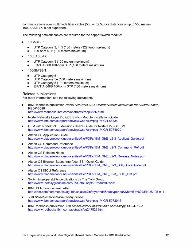
communications over multimode fiber cables (50µ or 62.5µ) for distances of up to 550 meters. 1000BASE-LX is not supported.
The following network cables are required for the copper switch module:
10BASE-T:
UTP Category 3, 4, 5 (100 meters (328 feet) maximum)100-ohm STP (100 meters maximum)
100BASE-TX:
UTP Category 5 (100 meters maximum)EIA/TIA-568 100-ohm STP (100 meters maximum)
1000BASE-T:
UTP Category 6 UTP Category 5e (100 meters maximum)UTP Category 5 (100 meters maximum)EIA/TIA-568B 100-ohm STP (100 meters maximum)
Related publicationsFor more information, see the following documents:
IBM Redbooks publication Nortel Networks L2/3 Ethernet Switch Module for IBM BladeCenter , REDP-3586http://www.redbooks.ibm.com/abstracts/redp3586.html
Nortel Networks Layer 2-3 GbE Switch Module Installation Guide http://www.ibm.com/support/docview.wss?uid=psg1MIGR-58334
OFM with Nortel/BNT Extensions User's Guide for Nortel L2-3 GbESM http://www.ibm.com/support/docview.wss?uid=psg1MIGR-5074970
Alteon OS Application Guidehttp://www.bladenetwork.net/userfiles/file/PDFs/IBM_GbE_L2-3_Applicat_Guide.pdf
Alteon OS Command Referencehttp://www.bladenetwork.net/userfiles/file/PDFs/IBM_GbE_L2-3_Command_Ref.pdf
Alteon OS Release Noteshttp://www.bladenetwork.net/userfiles/file/PDFs/IBM_GbE_L2-3_Release_Notes.pdf
Alteon OS Browser-Based Interface (BBI) Quick Guidehttp://www.bladenetwork.net/userfiles/file/PDFs/IBM_GbE_L2-3_BBI_QuickGuide.pdf
Alteon OS ISCLI Referencehttp://www.bladenetwork.net/userfiles/file/PDFs/IBM_GbE_L2-3_ISCLI_Ref.pdf
Switch interoperability certifications by The Tolly Grouphttp://www.thetollygroupinc.com/TVDetail.aspx?ProductID=296
IBM US Announcement Letterhttp://ibm.com/common/ssi/cgi-bin/ssialias?infotype=dd&subtype=ca&&htmlfid=897/ENUS105-011
IBM BladeCenter Interoperability Guidehttp://www.ibm.com/support/docview.wss?uid=psg1MIGR-5073016
IBM Redbooks publication IBM BladeCenter Products and Technology, SG24-7523http://www.redbooks.ibm.com/abstracts/sg247523.html
BNT Layer 2/3 Copper and Fiber Gigabit Ethernet Switch Modules for IBM BladeCenter 13
NoticesThis information was developed for products and services offered in the U.S.A.
IBM may not offer the products, services, or features discussed in this document in other countries. Consult your local IBM representative for information on the products and services currently available in your area. Any reference to an IBM product, program, or service is not intended to state or imply that only that IBM product, program, or service may be used. Any functionally equivalent product, program, or service that does not infringe any IBM intellectual property right may be used instead. However, it is the user's responsibility to evaluate and verify the operation of any non-IBM product, program, or service. IBM may have patents or pending patent applications covering subject matter described in this document. The furnishing of this document does not give you any license to these patents. You can send license inquiries, in writing, to:
IBM Director of Licensing, IBM Corporation, North Castle Drive, Armonk, NY 10504-1785 U.S.A.
The following paragraph does not apply to the United Kingdom or any other country where such provisions are inconsistent with local law: INTERNATIONAL BUSINESS MACHINES CORPORATION PROVIDES THIS PUBLICATION "AS IS" WITHOUT WARRANTY OF ANY KIND, EITHER EXPRESS OR IMPLIED, INCLUDING, BUT NOT LIMITED TO, THE IMPLIED WARRANTIES OF NON-INFRINGEMENT, MERCHANTABILITY OR FITNESS FOR A PARTICULAR PURPOSE. Some states do not allow disclaimer of express or implied warranties in certain transactions, therefore, this statement may not apply to you. This information could include technical inaccuracies or typographical errors. Changes are periodically made to the information herein; these changes will be incorporated in new editions of the publication. IBM may make improvements and/or changes in the product(s) and/or the program(s) described in this publication at any time without notice.
Any references in this information to non-IBM Web sites are provided for convenience only and do not in any manner serve as an endorsement of those Web sites. The materials at those Web sites are not part of the materials for this IBM product and use of those Web sites is at your own risk.IBM may use or distribute any of the information you supply in any way it believes appropriate without incurring any obligation to you. Information concerning non-IBM products was obtained from the suppliers of those products, their published announcements or other publicly available sources. IBM has not tested those products and cannot confirm the accuracy of performance, compatibility or any other claims related to non-IBM products. Questions on the capabilities of non-IBM products should be addressed to the suppliers of those products. This information contains examples of data and reports used in daily business operations. To illustrate them as completely as possible, the examples include the names of individuals, companies, brands, and products. All of these names are fictitious and any similarity to the names and addresses used by an actual business enterprise is entirely coincidental.
Any performance data contained herein was determined in a controlled environment. Therefore, the results obtained in other operating environments may vary significantly. Some measurements may have been made on development-level systems and there is no guarantee that these measurements will be the same on generally available systems. Furthermore, some measurement may have been estimated through extrapolation. Actual results may vary. Users of this document should verify the applicable data for their specific environment.
COPYRIGHT LICENSE:
This information contains sample application programs in source language, which illustrate programming techniques on various operating platforms. You may copy, modify, and distribute these sample programs in any form without payment to IBM, for the purposes of developing, using, marketing or distributing application programs conforming to the application programming interface for the operating platform for which the sample programs are written. These examples have not been thoroughly tested under all conditions. IBM, therefore, cannot guarantee or imply reliability, serviceability, or function of these programs.
© Copyright International Business Machines Corporation 2009. All rights reserved.Note to U.S. Government Users Restricted Rights -- Use, duplication or disclosure restricted byGSA ADP Schedule Contract with IBM Corp.
BNT Layer 2/3 Copper and Fiber Gigabit Ethernet Switch Modules for IBM BladeCenter 14
This document was created or updated on April 29, 2009.
Send us your comments in one of the following ways:Use the online Contact us review form found at:ibm.com/redbooksSend your comments in an e-mail to:[email protected] your comments to:IBM Corporation, International Technical Support OrganizationDept. HYTD Mail Station P0992455 South RoadPoughkeepsie, NY 12601-5400 U.S.A.
This document is available online at http://www.ibm.com/redbooks/abstracts/tips0689.html .
TrademarksIBM, the IBM logo, and ibm.com are trademarks or registered trademarks of International Business Machines Corporation in the United States, other countries, or both. These and other IBM trademarked terms are marked on their first occurrence in this information with the appropriate symbol (® or ™), indicating US registered or common law trademarks owned by IBM at the time this information was published. Such trademarks may also be registered or common law trademarks in other countries. A current list of IBM trademarks is available on the Web at http://www.ibm.com/legal/copytrade.shtml
The following terms are trademarks of the International Business Machines Corporation in the United States, other countries, or both:
BladeCenter®IBM®Power Systems™Redbooks®Redbooks (logo)®System x®WebSphere®
BNT, and the BLADE logo are registered trademarks of BLADE Network Technologies, Inc.
Microsoft, and the Windows logo are trademarks of Microsoft Corporation in the United States, other countries, or both.
UNIX is a registered trademark of The Open Group in the United States and other countries.
Other company, product, or service names may be trademarks or service marks of others.
Top Related