


Languages
Pages
Legal

Biotelemetry: A Review of the Art and Some Interesting
Circuits for Low-Power, Low-Noise Frequency Synthesis
Ron Spencer, Ph.D. Postdoctoral Candidate Seminar
September 25, 2003
September, 25, 2003 The Krasnow Institute Seminar
Preview
Biotelemetry: What is it and why use it? Prior Work & Typical Specs Basic architecture of Telemetric
Transceiver Power Reduction Strategies Data Conversion (using converters)
Frequency Synthesis: - PLLs - VCOs (using magnetic coupling) - Frequency division (using injection-locking)
Summary

September, 25, 2003 The Krasnow Institute Seminar
What is it and why would you use it?
Necessity - Implantable prosthetics - retinal, cochlear,
pacemaker - Animal tracking - freedom of movement Quality of measurement -
tethering forces on electrodes Convenience
- Multi-electrode stimulation/recording - Vital sign monitoring in critical situations
Why Use It?
Biotelemetry is the wireless transmission of automatically measured physiological data from the point of sensing to a remote location. However, in practice the term also refers bidirectional wireless data transfer and remote powering.
September, 25, 2003 The Krasnow Institute Seminar
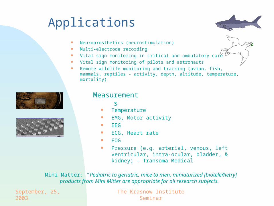
Applications Neuroprosthetics (neurostimulation) Multi-electrode recording Vital sign monitoring in critical and ambulatory care Vital sign monitoring of pilots and astronauts Remote wildlife monitoring and tracking (avian, fish, mammals,
reptiles - activity, depth, altitude, temperature, mortality)
Temperature EMG, Motor activity EEG ECG, Heart rate EOG Pressure (e.g. arterial, venous, left ventricular, intra-
ocular, bladder, & kidney) - Transoma Medical
Measurements
Mini Matter: “Pediatric to geriatric, mice to men, miniaturized [biotelemetry] products from Mini Mitter are appropriate for all research subjects.”
September, 25, 2003 The Krasnow Institute Seminar
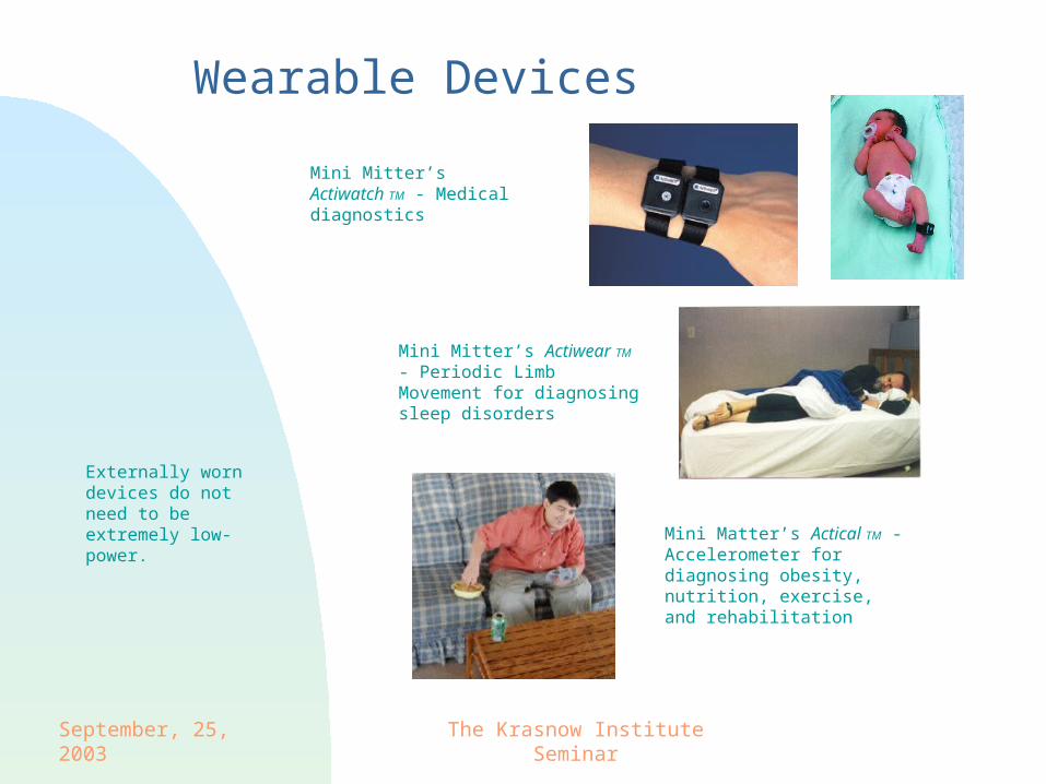
Wearable Devices Mini Mitter’s Actiwatch TM - Medical diagnostics
Mini Mitter’s Actiwear TM - Periodic Limb Movement for diagnosing sleep disorders
Mini Matter’s Actical TM - Accelerometer for diagnosing obesity, nutrition, exercise, and rehabilitation
Externally worn devices do not need to be extremely low- power.
September, 25, 2003 The Krasnow Institute Seminar
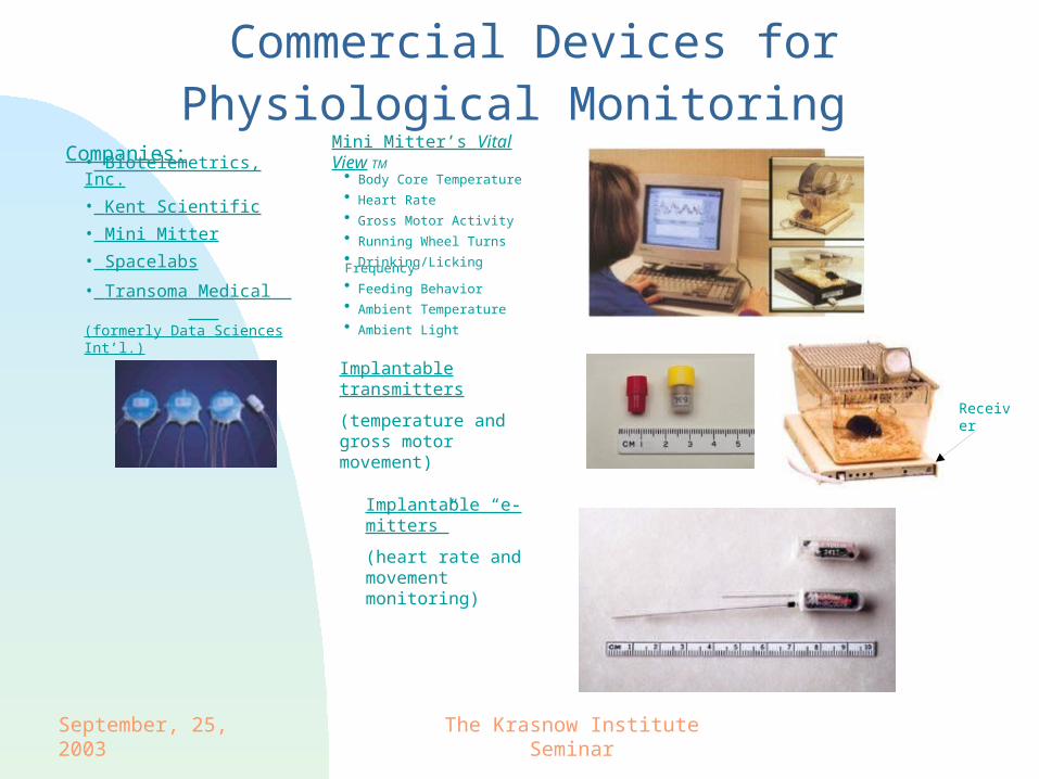
Commercial Devices for Physiological Monitoring
Mini Mitter’s Vital View TM
Body Core Temperature Heart Rate Gross Motor Activity Running Wheel Turns Drinking/Licking Frequency Feeding Behavior Ambient Temperature Ambient Light
Implantable transmitters
(temperature and gross motor movement)
Implantable “e-mitters”
(heart rate and movement monitoring)
Receiver
Companies:
• Biotelemetrics, Inc.
• Kent Scientific
• Mini Mitter
• Spacelabs
• Transoma Medical (formerly Data Sciences Int’l.)
September, 25, 2003 The Krasnow Institute Seminar
Prior Work Monitoring and Recording
Neurostimulation
Sieve electrode recording (Akin et al.) Sympathetic nerve activity and ECG measurement (Enokawa, et al.) Auditory experimentation (Lukes, et al.) Monitoring of freely moving animals and insects Single neuron discharge in monkeys
Retinal prosthesis - retinitis pigmentosa and macular degeneration - MIT
- 2nd Sight (Alfred Mann Foundation)- Gregg Suaning, U. New South Wales (100 ch. Bidirectional RF-CMOS)
Cochlear prosthesis - Advanced Bionics Corporation
Pacemakers
September, 25, 2003 The Krasnow Institute Seminar
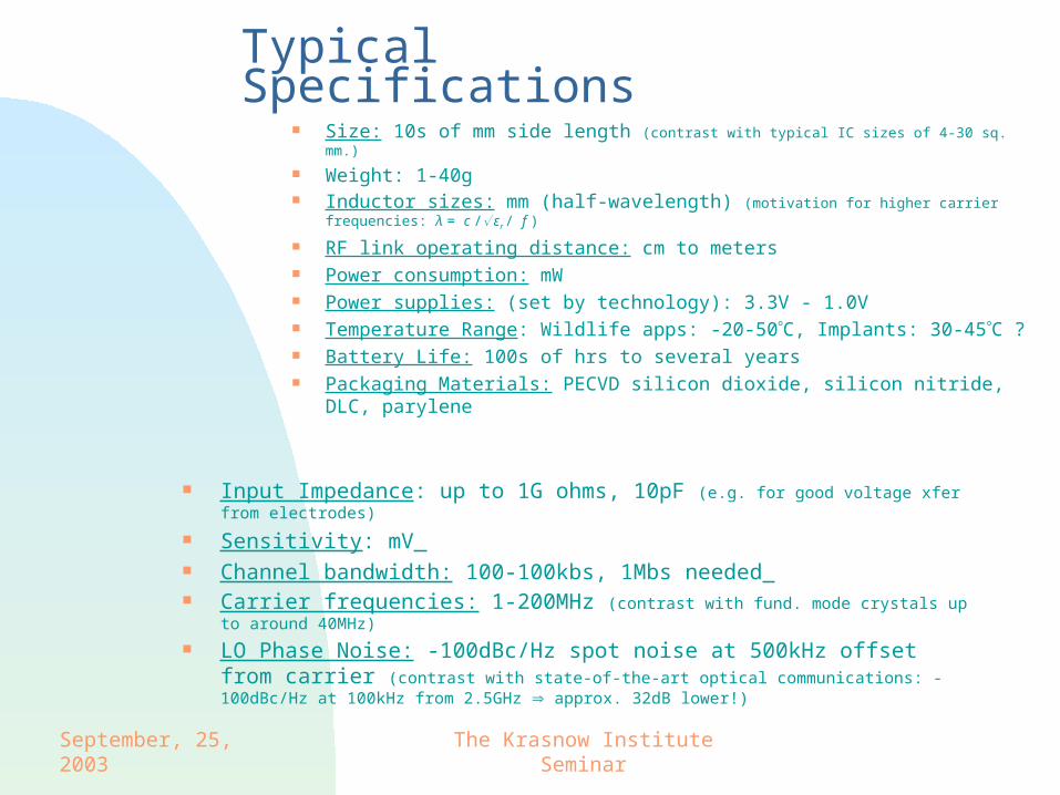
Typical Specifications
Input Impedance: up to 1G ohms, 10pF (e.g. for good voltage xfer from electrodes)
Sensitivity: mV Channel bandwidth: 100-100kbs, 1Mbs needed Carrier frequencies: 1-200MHz (contrast with fund. mode crystals up to around
40MHz)
LO Phase Noise: -100dBc/Hz spot noise at 500kHz offset from carrier (contrast with state-of-the-art optical communications: -100dBc/Hz at 100kHz from 2.5GHz approx. 32dB lower!)
Size: 10s of mm side length (contrast with typical IC sizes of 4-30 sq. mm.)
Weight: 1-40g Inductor sizes: mm (half-wavelength) (motivation for higher carrier frequencies: λ =
c / εr / f )
RF link operating distance: cm to meters Power consumption: mW Power supplies: (set by technology): 3.3V - 1.0V Temperature Range: Wildlife apps: -20-50C, Implants: 30-45C ? Battery Life: 100s of hrs to several years Packaging Materials: PECVD silicon dioxide, silicon nitride, DLC,
parylene
September, 25, 2003 The Krasnow Institute Seminar
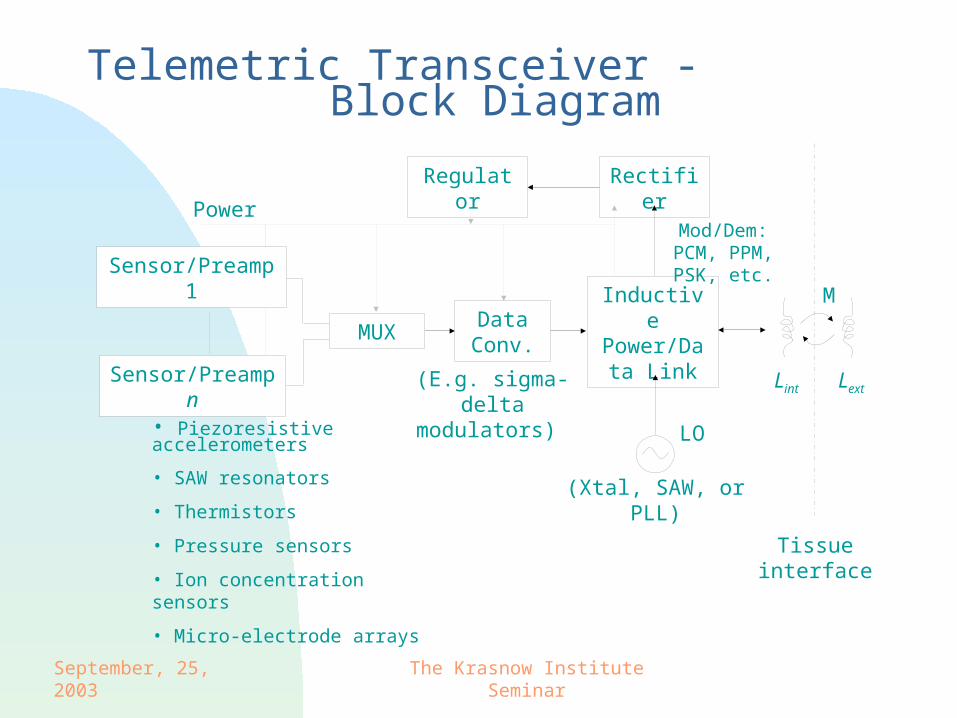
Telemetric Transceiver - Block Diagram
Sensor/Preamp n
Data Conv.
RectifierRegulator
MUX
Sensor/Preamp 1
Power
Inductive Power/Data
Link
(E.g. sigma-delta modulators)
LO
(Xtal, SAW, or PLL)
Tissue interface
• Piezoresistive accelerometers
• SAW resonators
• Thermistors
• Pressure sensors
• Ion concentration sensors
• Micro-electrode arrays
M
LextLint
Mod/Dem: PCM, PPM, PSK, etc.
September, 25, 2003 The Krasnow Institute Seminar
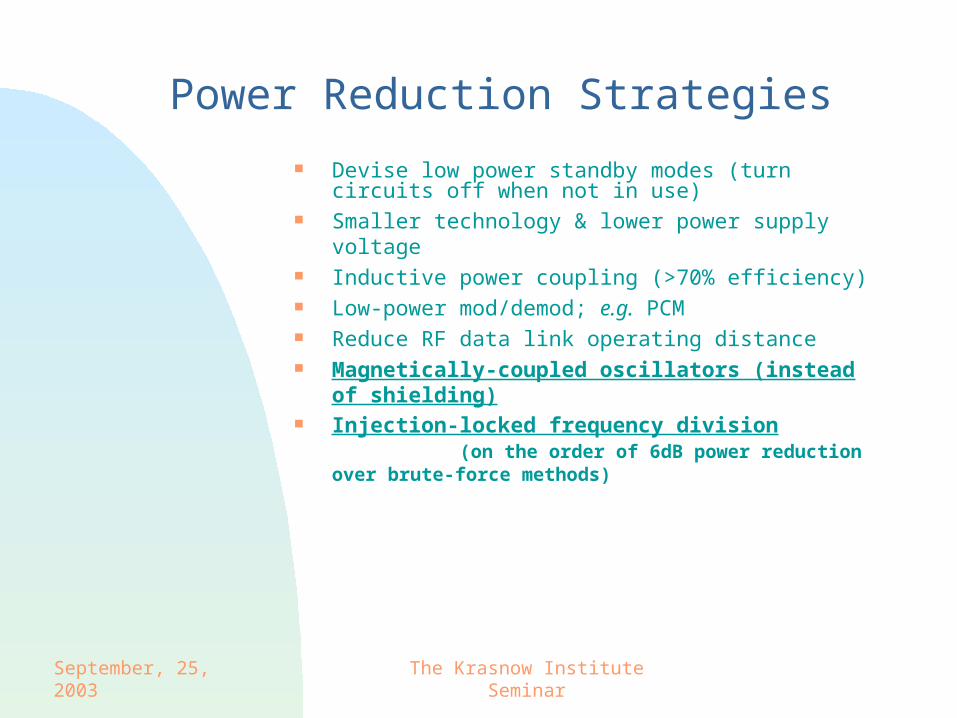
Power Reduction Strategies
Devise low power standby modes (turn circuits off when not in use)
Smaller technology & lower power supply voltage Inductive power coupling (>70% efficiency) Low-power mod/demod; e.g. PCM Reduce RF data link operating distance Magnetically-coupled oscillators (instead of shielding) Injection-locked frequency division (on the
order of 6dB power reduction over brute-force methods)
September, 25, 2003 The Krasnow Institute Seminar
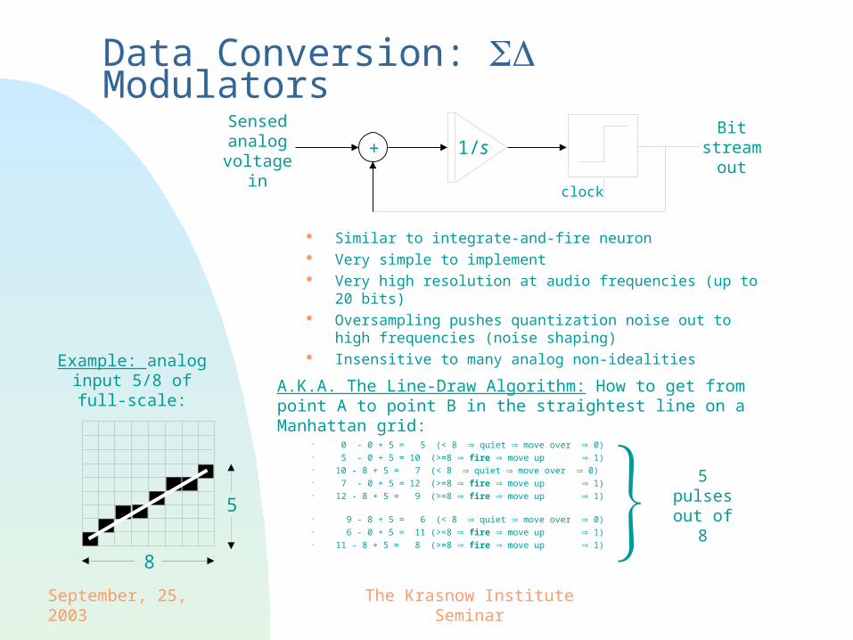
Data Conversion: Modulators
Similar to integrate-and-fire neuron Very simple to implement Very high resolution at audio frequencies (up to 20 bits) Oversampling pushes quantization noise out to high
frequencies (noise shaping) Insensitive to many analog non-idealities
+ 1/sSensed analog
voltage in
Bit stream
out
8
5
A.K.A. The Line-Draw Algorithm: How to get from point A to point B in the straightest line on a Manhattan grid:
clock
0 - 0 + 5 = 5 (< 8 quiet move over 0) 5 - 0 + 5 = 10 (>=8 fire move up 1) 10 - 8 + 5 = 7 (< 8 quiet move over 0) 7 - 0 + 5 = 12 (>=8 fire move up 1) 12 - 8 + 5 = 9 (>=8 fire move up 1) 9 - 8 + 5 = 6 (< 8 quiet move over 0) 6 - 0 + 5 = 11 (>=8 fire move up 1) 11 - 8 + 5 = 8 (>=8 fire move up 1)
5 pulses out of 8
Example: analog input 5/8 of full-scale:

September, 25, 2003 The Krasnow Institute Seminar
Frequency Synthesis: Multiplying PLL
PLLs drive the phase of an oscillator to be some fixed offset from that of the input.
Ideally, the resonant frequency of the VCO is exactly M times ωi. If not, the VCO is adjusted to the correct frequency by H(s).
H(s)+ Kv/s
(φo φi)
(ωo Mωi)
Vvco=φo
Freq. Divider (M)
Vi cos(ωi t+φi) Vo cos(ωot+φo)(φe 0)
ωf = ωo /M
September, 25, 2003 The Krasnow Institute Seminar
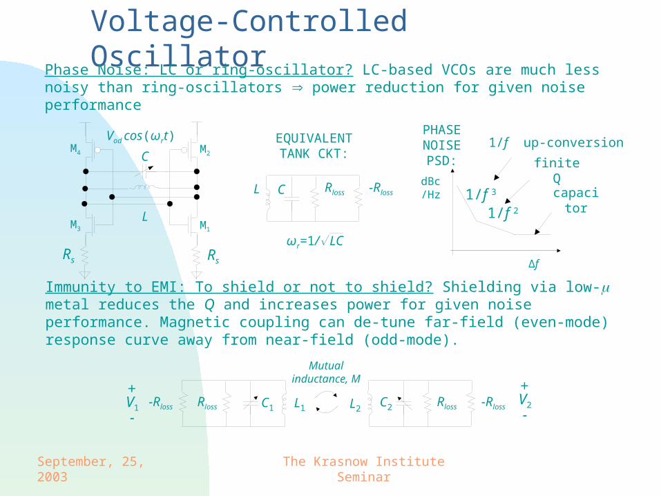
Vod cos(ωrt)
Voltage-Controlled Oscillator
finite Q
ωr=1/ LC
RlossCL -Rloss
M1
M2
M3
M4
EQUIVALENT TANK CKT:C
L
Rs Rs
1/f 3
1/f 2
Δf
dBc/Hz
Phase Noise: LC or ring-oscillator? LC-based VCOs are much less noisy than ring-oscillators power reduction for given noise performance
Immunity to EMI: To shield or not to shield? Shielding via low- metal reduces the Q and increases power for given noise performance. Magnetic coupling can de-tune far-field (even-mode) response curve away from near-field (odd-mode).
RlossC2L2-RlossRloss C1 L1
-RlossV1
+
-V2
+
-
Mutual inductance, M
1/f up-conversion
capacitor
PHASE NOISE PSD:
September, 25, 2003 The Krasnow Institute Seminar
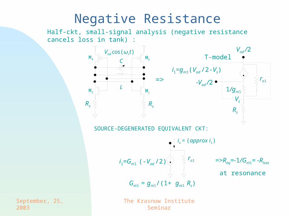
Half-ckt, small-signal analysis (negative resistance cancels loss in tank) :
Vod cos(ωrt)Vod /2
T-model
-Vod /2
i1=gm1(Vod /2-Vs)
Negative Resistance
ro1
1/gm1
Rs
io = (approx i1)
ro1i1=Gm1 (-Vod /2)
Gm1 = gm1/(1+ gm1 Rs)
SOURCE-DEGENERATED EQUIVALENT CKT:
=>Req=-1/Gm1= -Rloss
at resonance
M1
M2
M3
M4
=>
C
L
Rs Rs
Vs
September, 25, 2003 The Krasnow Institute Seminar
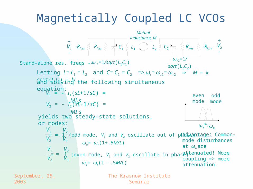
Magnetically Coupled LC VCOs
V1 = - I1(sL+1/sC) = MI2s
Letting L= L1 = L2 and C= C1 = C2 => ωr= ωr1= ωr2 M = k sqrt(L1L2) = kL
V2 = - I2(sL+1/sC) = MI1s
and solving the following simultaneous equation:
yields two steady-state solutions, or modes:
V1
V2
=V2
V1
= -1 (odd mode, V1 and V2 oscillate out of phase)
V1
V2
=V2
V1
= 1 (even mode, V1 and V2 oscillate in phase)
ωr2=1/sqrt(L2C2)ωr1=1/sqrt(L1C1)
RlossC2L2-RlossRloss C1 L1
-RlossV1
+
-V2
+
-
Mutual inductance, M
Advantage: Common-mode disturbances at ωo
are attenuated! More coupling => more attenuation.
ωo= ωr(1+.5M/L)
ωe= ωr(1 - .5M/L)
Stand-alone res. freqs ->
ωr ωoωe
odd mode
even mode
September, 25, 2003 The Krasnow Institute Seminar
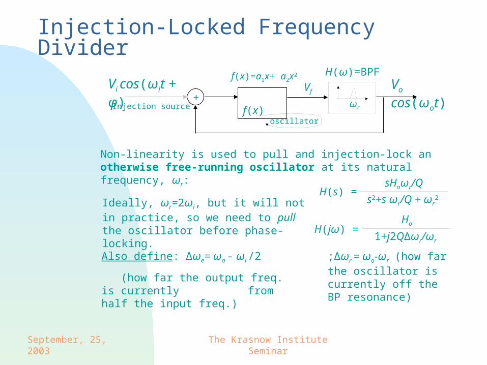
Injection-Locked Frequency Divider
Ideally, ωr=2ωi, but it will not in practice, so we need to pull the oscillator before phase-locking.
Non-linearity is used to pull and injection-lock an otherwise free-running oscillator at its natural frequency, ωr:
H(s) =sHoωr/Q
s2+s ωr/Q + ωr2
;Δωr = ωo-ωr (how far the oscillator is currently off the BP resonance)
Vo cos(ωot) f(x)+
f(x)=a1x+ a2x2
Vi cos(ωit + φ)H(ω)=BPF
Injection source
oscillator
ωr
Vf
Ho
1+j2QΔωr/ωr
Also define: Δωe= ωo - ωi /2
(how far the output freq. is currently from half the input freq.)
H(jω) =
September, 25, 2003 The Krasnow Institute Seminar
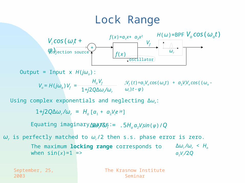
Vo = H(jωo)Vf =Ho Vf
1+j2QΔωr/ωr
Output = Input x H(jωo):
;Vf (t)=a1Vo cos(ωot) + a2ViVo cos((ωo - ωi)t - φ)
1+j2QΔωr /ωr = Ho [a1 + a2Vie jφ]
Equating imaginary parts:
Using complex exponentials and neglecting Δωe:
Δωr/ωr = .5Ho a2Visin(φ)/Q
The maximum locking range corresponds to when sin(x)=1 => Δωr /ωr < Ho a2Vi /2Q
If ωr is perfectly matched to ωi /2 then s.s. phase error is zero.
Vo cos(ωot)
f(x)+
f(x)=a1x+ a2x2
Vi cos(ωit + φ)H(ω)=BPF
Injection source
oscillator
ωr
Vf
Lock Range
September, 25, 2003 The Krasnow Institute Seminar
Vi cos(ωit)
Vod cos(ωot+ φo) L L
CCVs
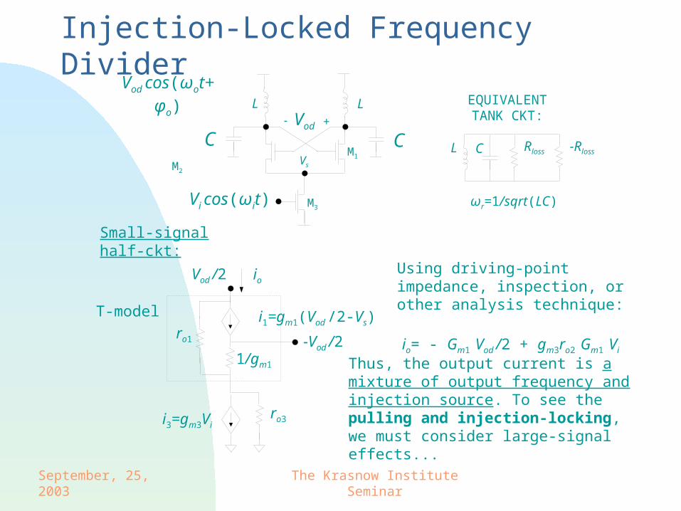
Injection-Locked Frequency Divider
M1
M2
M3
Vod +-
ωr=1/sqrt(LC)
RlossCL -Rloss
Small-signal half-ckt:
Vod /2
ro1
1/gm1
T-model
-Vod /2
i1=gm1(Vod /2-Vs)
i3=gm3Viro3
ioUsing driving-point impedance, inspection, or other analysis technique:
io= - Gm1 Vod /2 + gm3ro2 Gm1 Vi
Thus, the output current is a mixture of output frequency and injection source. To see the pulling and injection-locking, we must consider large-signal effects...
EQUIVALENT TANK CKT:
September, 25, 2003 The Krasnow Institute Seminar
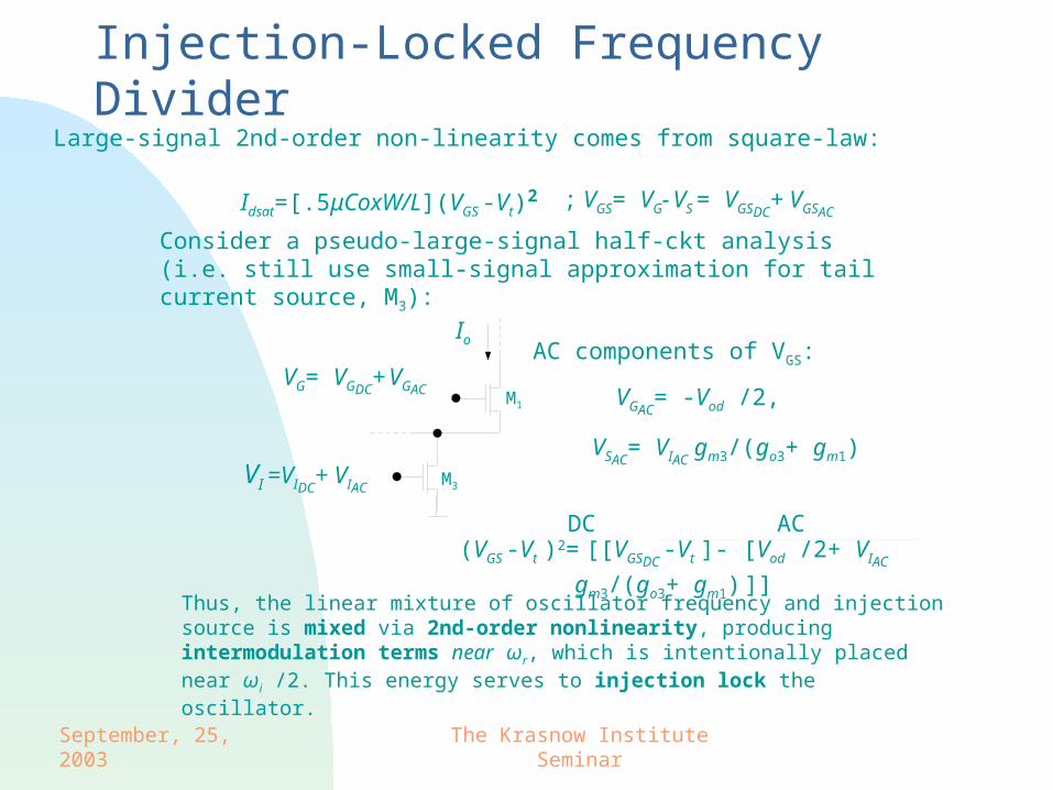
Consider a pseudo-large-signal half-ckt analysis (i.e. still use small-signal approximation for tail current source, M3):
Idsat=[.5μCoxW/L](VGS -Vt)2 ; VGS= VG- VS = VGSDC
+ VGSAC
Io
M1
M3VI =VIDC
+ VIAC
VG= VGDC+ VGAC
AC components of VGS:
VGAC= -Vod /2,
VSAC= VIAC
gm3/(go3+ gm1)
DC AC
(VGS -Vt )2= [[VGSDC -Vt ]- [Vod /2+ VIAC gm3/(go3+ gm1) ]]
Large-signal 2nd-order non-linearity comes from square-law:
Thus, the linear mixture of oscillator frequency and injection source is mixed via 2nd-order nonlinearity, producing intermodulation terms near ωr, which is intentionally placed near ωi /2. This energy serves to injection lock the oscillator.
Injection-Locked Frequency Divider
September, 25, 2003 The Krasnow Institute Seminar
Summary Biotelemetry is useful for
- Neural stimulation (data in device)
- Neural recording (device data out)
- Eliminating tethering forces
- Vital sign monitoring
- Animal tracking
Biotelemetry represents a multidisciplinary research area that enables collaboration and offers a diverse EE design experience: • ckt design • EM • communications • sensor design • transmission-line/waveguide design • antenna design
Today’s CMOS technology may be leveraged to reduce power and size, improve performance, and increase throughput
References available upon request. THANK YOU!
Top Related