

![[Mars] Mars Minus Bisha - Leigh Brackett](https://static.fdocuments.net/doc/165x107/55cf94d9550346f57ba4d4d5/mars-mars-minus-bisha-leigh-brackett.jpg)

![[Mars] the Road to Sinharat - Leigh Brackett](https://static.fdocuments.net/doc/165x107/55cf94d9550346f57ba4d4d1/mars-the-road-to-sinharat-leigh-brackett.jpg)


Languages
Pages
Legal


1
1
2
2
3
3
4
4
5
5
6
6
7
7
8
8
A A
B B
C C
D D
E E
F F
G G
H H
TY-TBW
DESCRIPTIONPART NUMBERQTYITEMPLATE ASSEMBLYTY-TBW-211TRUSS ASM.TY-TBW-112HYDRAULIC PUMPTY-TBW-413HYDRAULIC RAMTY-TBW-514SPRINGTBW-725CROSS BARTY-TBW-1116TIRE ASM.W-41066271/2" SNAP RING97633A200481/2 SHAFT 5/8 O.D. 3/8 LONG FLANGED SLEEVE BEARING6338K417493/8-16 X 1 BHCS92949A6244101/2 X 2 SHCS SHOULDER BOLT 3/8-16 THREAD91259A7202111/4-20 X 3/8 HEX DRIVE ROUNDED HEAD SCREW91306A373412HYDRAULIC HOSE ASM.TY-TBW-141131/2" SHAFT 5/8" ID, 1/2" LONG, 1/16" FLANGE THICKNESS6338K572414PINTY-TBW-3-22153/8-16 HEX FLANGE LOCKNUTTHIS PART NUMBER VARIES DEPENDING ON
THE VERSION #92018A430 IS SHOWN616
3/8-16 X 1 1/4 FOR 3 1/2 DIA. U-BOLTTHIS PART NUMBER VARIES DEPENDING ON THE VERSIONS #3043T440 IS SHOWN
317
3/8 LOCK WASHER91101A0314183/4-16 CASTLE NUT S.S.AN310-C122193/4" SAE WASHER91083A036220SHAFT LOCK6436K38121
BAC
BRACKETT AIRCRAFT CO., INC.
7045 FLIGHTLINE DR.KINGMAN, AZ 86401
928-757-4005BRACKETTAIRCRAFT.COM
BAC
1
8
3
47
16
2
FINISH: POWDER COAT BLACKSHIPPING SPECS.: 40" X 48" X 28" @ 175 LBS.
HYDRAULIC WHEEL LIFT
15
9
10
6
14
11
17
12
LIFT PART NUMBER APPLICABLE TOW BAR TYPE
TY-TBW-3RD 3" ROUND PIPE
TY-TBW-4RD 4" ROUND PIPE
TY-TBW-5RD 5" ROUND PIPE
TY-TBW-4SQ 4" SQUARE TUBING
13
1819
20
5
21
Page 1 of 5 11/2018

ASSEMBLY OF TY‐TBW
BRACKETT AIRCRAFT CO., INC. PH: 928‐757‐4005 │ FAX: 928‐757‐1948 EMAIL: [email protected] WEBSITE: WWW.BRACKETAIRCRAFT.COM
STEP 1
STEP 2
Page 2 of 5 11/2018
ASSEMBLY OF TY‐TBW
BRACKETT AIRCRAFT CO., INC. PH: 928‐757‐4005 │ FAX: 928‐757‐1948 EMAIL: [email protected] WEBSITE: WWW.BRACKETAIRCRAFT.COM
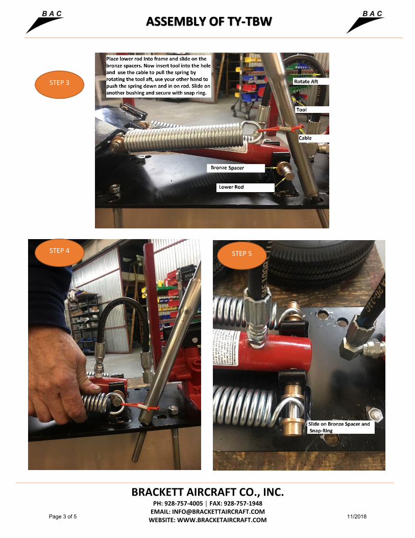
STEP 3
STEP 4 STEP 5
Page 3 of 5 11/2018

BRACKETT AIRCRAFT CO., INC. PH: 928-757-4005 │ FAX: 928-757-1948
EMAIL: [email protected] WEBSITE: WWW.BRACKETAIRCRAFT.COM
TY-TBW TOWBAR HYDRAULIC WHEEL LIFT
The TY-TBW is designed as an add on lifting device for most aircraft Towbar’s to facilitate towing to the aircraft and ease of hook up from aircraft to the Towbar by hydraulically lifting the Towbar Head to the aircraft attachment point. The TY-TBW tows easily with the 4:10 pneumatic tires and the wide stance helps prevent Towbar roll overs on fast sharp turns. The TY-TBW Wheel Lift can be installed on Towbar Tubes of 3 ½”, 4 ½”, 5 ½” O.D.’s or squares. INSTALLATION ON TOWBAR FRAME: Use 3 each U-Bolts to mount Plate Assembly (#1) to Towbar. Location can vary from cen-ter balance (with Tow Head installed) to Tow Head. Closer to the center point, the higher the lift of the Tow Head to attach to the aircraft. Next, install Shaft Stop (#21) to prevent the Towbar from injuring your toes or feet, from rapid release of the Hydraulic Ram. This Stop can be installed anywhere along the Ram Shaft. OPERATION: To operate the Wheel Lift, rotate the knob on the pump clockwise to close and pump the wheels down to the desired height. After hooking Towbar Head to the aircraft and hooking Tug to the vehicle, release Pump knob to bring wheels up so as not to drag when towing. Wheels are lifted upwards by the extension Springs. MAINTENANCE: Check U-bolts, nuts, wheels, springs, snap rings, truss pivot point and oil if necessary. Check and replace hose as needed. Grease wheel bearings, as needed, or once per year. Check Pump oil reservoir in level position and wheels fully retracted. Top off with jack oil if needed with ISO AW 32. Do not use hydraulic fluid because it will deteriorate the seals.
Page 4 of 5 11/2018

Tire/Wheel Inspection:
• Any tire, no matter how well constructed, may fail as a result of punctures, impact damage, improper
inflation, overloading, or other conditions resulting from use or misuse. Tire failure may create a risk of
property damage and serious personal injury. To reduce risk of tire failure, we strongly recommend you read
and follow all safety information.
• Inspect wheels and tires for wear, cracks, cuts, or damage. Bumps or bulges may indicate separation within
the tire body. A damaged tire can suddenly fail causing damage to property or serious personal injury.
• Inspect tire for adequate tread depth 3/32nd inch (2.4 millimeters).
Tire Inflation:
• Always keep tire inflated to the manufactures recommended pressure. Tire sidewall stamping information
will tell you the recommended cold air pressure. Check tire inflation before moving aircraft.
◦ Air Hawk 15 X 6.00 6 ply 68 psi
◦ Air Hawk 18 X 5.50 8 ply 105 psi
◦ Carlisle 5.30/4.50-6 6 ply 95 psi
◦ Kenda 4.10/3.50-4 6 ply 75 psi
◦ Kenda 4.10/3.50-6 6 ply 80 psi
◦ STA 14 X 5.00-5 14 ply 130 psi
◦ Air Hawk 5:00-5 10 ply 90 psi
• Use valve caps to keep valve cores clean, clear of debris and to help guard against air leakage.
• Under-inflated tires will cause damage leading to failure that could result in damage to property or serious
personal injury.
• Over-inflated tires are more likely to become punctured, cut, or broken by sudden impact leading to failure
that could result in damage to property or serious personal injury.
Page 5 of 5 11/2018
Top Related