
![[eBook Acoustics Audio HiFi DIY]How to Build an Electrostatic Tweeter{SHACKMAN.de}](https://static.fdocuments.net/doc/165x107/563db811550346aa9a903f06/ebook-acoustics-audio-hifi-diyhow-to-build-an-electrostatic-tweetershackmande.jpg)


Languages
Pages
Legal

• ΜΑΡΝΗ 8 ΑΘΗΝΑ 10433 • ΤΗΛ. 210 3845676 – 210 3845272 FAX. 210 3809747 • e-mail: [email protected] •
FURUTECH
The Appropriate Selection and Use of Audio Cables
Considerable interest has, in recent years, focused on the hitherto neglected, yet complex
subject of high fidelity cables and interconnects.
Regrettably, conflicting claims from a plethora of producers has led to a great deal of
confusion. As a result, it’s extremely difficult to separate fact from fiction, which is naturally
frustrating for the potential purchaser, particularly when it’s obvious that cost effective sound
quality improvements of a high order may be affected, simply by choosing as appropriate
interconnect or cable.
In order that a precise interface between Hi Fi components may be successfully achieved, the
specifications for the design of an interconnect dedicated to its specific purpose requires to be
appreciated and whilst subjective assessment through listening is recommended, without the
benefit of accurate specifications, subjective assessment alone will often result in an
inappropriate purchase.
We sincerely trust that the following may introduce the reader to a meaningful correlation
between cable design and sound quality, thereby assisting in the selection of appropriate
cables and interconnects dedicated to their respective purposes.
There’s More to Sound Quality Than Conductor Specifications
The following three types of cable are regularly employed in Hi Fi systems.
A.C. power supply cables.
Interconnect cables for the transmission of delicate audio signals.
Speaker cables for the transmission of signals from amplifiers to speakers.
Whilst A.C. power cables do influence quality, fundamental to the excellence of the system are
the latter two, the interconnect and the speaker cables. In the design of these cables, three
principal factors contribute to quality, these are:
Conductor material specifications.
Insulation material specifications.
Cable construction specifications.
The appropriate selection of quality conductor materials contribute to enhanced resolution,
clear bass, image, height and depth, whilst the selection of insulation materials, together with
construction methods, influence the accuracy of musical timbre and ambience.

• ΜΑΡΝΗ 8 ΑΘΗΝΑ 10433 • ΤΗΛ. 210 3845676 – 210 3845272 FAX. 210 3809747 • e-mail: [email protected] •
TPC
OFC
PCOCC TPC PCOCC
Conductor Types
TPC (Tough Pitch Copper)
TPC is a basic copper conductor widely employed for electric wires such as power leads and
occasionally in inexpensive audio leads.
The electrolyzed electric copper is melted once and cooled into a conductor electric wire
through repeated drawing into the desired size. The tough pitch copper which is melted and
cooled in air contains about 300~500ppm of oxygen.
OFC (Oxygen Free Copper)
OFC is produced in an inert gas, oxygen free process and thus it’s 10ppm represents a
relatively low oxygen content. OFC’s conductivity is of the order of 0.5% to 2% greater than
that of TPC. OFC may be annealed in order to reduce the crystal grain structure.
PCOCC (Pure Copper by Ohno Continuous Casting Process)
PCOCC represents ‘state of the art’ in conductor material technology. PCOCC is produced
from an exclusive and patented method of continuous casting, developed by Professor Ohno of
The Chiba Institute of Technology. The PCOCC process involves the use of a heated mold,
which produces a mono or single crystal ultra pure copper wire with insignificant oxygen and
hydrogen inclusion. The copper material transformation has additional significant advantages,
it reduces the ratio of stress to strain of the copper, therefore PCOCC has greater flexibility,
PCOCC has a higher specific gravity and a higher “Q” therefore PCOCC’s mechanical
isolation or resistance to electromagnetically induced vibration within a conductor is excellent.
PCOCC mono crystal copper wire has no crystal grain boundary in the signal transmission
direction, consequently, PCOCC doesn’t impede the extremely delicate audio signal and
features the lowest distortion factor of any available conductor material. Since it’s
introduction in 1986, continued research and development into PCOCC has resulted in even
greater purity. PCOCC with a purity of 99.99999% described as “7N” because of the seven
“nine’s”, will, in future, be a feature of very superior cables.

• ΜΑΡΝΗ 8 ΑΘΗΝΑ 10433 • ΤΗΛ. 210 3845676 – 210 3845272 FAX. 210 3809747 • e-mail: [email protected] •
The chemical and physical properties of copper ingot
PCOCC OFC TPC
Purity >99.997 >99.99 >99.9
× 8.938 8.926 8.75 Density
max 8.940 8.932 8.88
O2(ppm) <5 <10 200~500 Gas impurity
H2 (ppm) <0.25 <0.5 >0.3
Hydrogen embittrement Absolutely
none No Yes
The properties of the elementary materials
PCOCC LC-OFC TPC/OFC
Conductor diameter 5mmψ 15mmψ 1.6mmψ 0.9mmψ
The length of grain >500mm >50mm <0.5mm <0.05mm
The length of grain
after drawn to 0.1mm¢ >1,125.00m <13cm <4mm
The number of grain
in 2m length cable 1 >15 >400
• ΜΑΡΝΗ 8 ΑΘΗΝΑ 10433 • ΤΗΛ. 210 3845676 – 210 3845272 FAX. 210 3809747 • e-mail: [email protected] •
Differences due to Conductor Construction
Cable employ in their construction either a solid or a stranded configuration of wires for their conductors,
according to the application for which the cable is designed. Stranded wire is typically available in one of the
following three configurations, each of which exhibits it’s own characteristics.
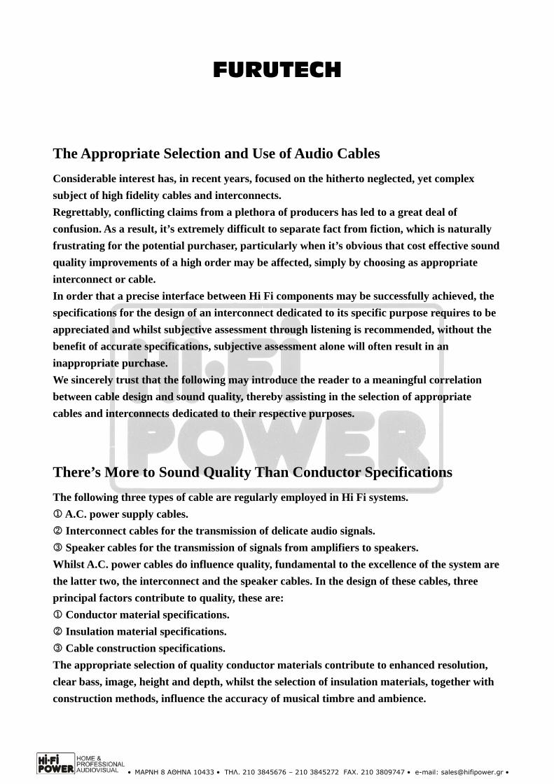
Bunch Stranded Conductor
The bunch stranded is a method of production whereby strands in the construction of the conductor are laid as a
bunch in the same direction. Typically, cables provided for power cables and sometimes, proprietary Hi Fi and
audio systems are produced from bunch stranded conductors. The cross-section of a stranded conductor is not
perfectly circular, therefore, cables of such construction employed for signal transmission suffer from a reflection
of the signal due to fluctuations of the characteristic impedance in the longitudinal direction of he cable, resulting
in a deleterious sound quality.
Concentric Lay Stranded Conductor
Concentric lay stranded consist usually, of multiple layer of concentric stranded wires. The center of the middle
conductor coincides with the center of the diameter of the other layers. Adjacent strand layers within the
conductors are usually laid in opposite directions. The uniform position relationship of the conductors in the
longitudinal direction form a perfect circle through their section, suitable to signal transmission and contribute
to a stabilisation of the characteristic impedance.
Rope Lay Stranded Conductor
Rope lay stranded is a kind of concentric lay stranded conductor having required members which are consist of
bunch or concentric lay stranded wires. Rope lay stranding is usually a superior design employed in
better quality speaker cables which require to having a large section yet remain flexible.
The Solid Conductor
The ultimate quality for conductors is achieved
from a solid PCOCC conductor. It may be noted
that all the compromises made in the design of the
three forementioned methods of production are
totally eliminated in a perfectly circular solid
conductor, which may be produced in a variety of
sizes according to the sectional area required. Such
materials are Super PCOCC, which are “AS
CAST” and are not reworked or drawn to size,
FS-2T15S speaker cable and FA-11S interconnect
cables are representative of “AS CAST”
conductors, these are best conductors which
Furutech manufacture and they feature in the
finest quality cables.

• ΜΑΡΝΗ 8 ΑΘΗΝΑ 10433 • ΤΗΛ. 210 3845676 – 210 3845272 FAX. 210 3809747 • e-mail: [email protected] •
Various Characteristics of Conductors
Conductor Resistance Attenuation of the signal is directly proportional to conductor resistance. Attenuation
represents the amount of energy consumed as the signal transmits along the cable, and the
lower the attenuation and therefore conductor resistance, the better.
The foregoing is of paramount importance in the case of speaker cables where a high
conductor resistance causes a decrease in the damping factor. The coil in a speaker generates
it’s own electromotive force which is fed back through a speaker cable and can, in extreme
cases, damage the power amplifier.
D.C. resistance is in direct proportion to the conductor’s sectional area and the material
employed, the greater the diameter and the purer the material, the lower is D.C. resistance.
When high frequencies are transmitted in A.C., a different set of values apply and conductor
resistance increases due to skin effect, proximity effect and eddy current loss. Illustrated are
the frequency characteristics of three Furutech speaker cables. FS-2T20P, FS-2T35P and
FS-2T15S, the former two are stranded designs of 2 sq mm and 3.5 sq mm respectively and
the third is a solid conductor of 1.5mm. It will be noted that in what is considered to be the
audible spectrum, from 20Hz to 20kHz the frequency characteristics of all three remain
relatively flat, however as the frequency increases from D.C. into A.C. the conductor
resistance increases correspondingly. It may be argued that these frequencies are inaudible,
but that’s not the case, it’s high frequencies which influence timbre and ambience and
contribute to a clean, smear free treble, therefore thoughtfully designed cables produced from
high quality materials and constructed with technical excellence together with an efficient
insulation are a prerequisite to Hi Fi excellence.
• ΜΑΡΝΗ 8 ΑΘΗΝΑ 10433 • ΤΗΛ. 210 3845676 – 210 3845272 FAX. 210 3809747 • e-mail: [email protected] •
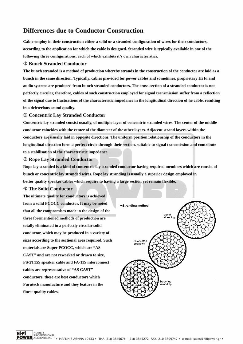
Skin Effect Flowing current tends to favor the conductor surface as the frequency rises. The situation is
considered to be due to the failure of the high frequency electromagnetic wave to enter the
conductor metal or a reaction of current within the conductor.
In practice, when high frequencies are transmitted down the peripheral surface, they don’t
flow through the central portion of the conductor and the reduction in the effective sectional
area results in an increase in conductor resistance, which causes an increase in attenuation
and a resultant degradation in sound quality.
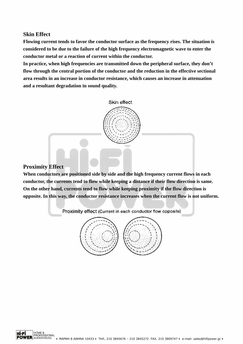
Proximity Effect When conductors are positioned side by side and the high frequency current flows in each
conductor, the currents tend to flow while keeping a distance if their flow direction is same.
On the other hand, currents tend to flow while keeping proximity if the flow direction is
opposite. In this way, the conductor resistance increases when the current flow is not uniform.

• ΜΑΡΝΗ 8 ΑΘΗΝΑ 10433 • ΤΗΛ. 210 3845676 – 210 3845272 FAX. 210 3809747 • e-mail: [email protected] •
Type of Insulation
Materials
The materials most frequently utilised for electronic cables are PVC (Polyvinyl Chloride) and
LDPE (Low Density Polyethylene). In commercial use, PVC is principally used for cables of
low voltages typically 600 volts or less. LDPE, with its good dielectric characteristics, is often
employed as an insulation material in communication cables for telephones etc. for high
voltage power cables and for video and digital audio interconnect cables.
Superior materials include FEP (Teflon) and PP (Polypropylene). Teflon has excellent
dielectric characteristics. Teflon is a heat resistant material as is evident from it’s use as a
surface material for pots and pans, which means the extrusion temperature for insulating a
conductor requires to be of a high order, generally 400 to 500 degrees centigrade and at these
high temperature the conductor surface will be oxidized.
Polypropylene is a pure, stable material with excellent insulation characteristics including
dielectric constant. PP also exhibits better mechanical properties such as isolation to vibration
and is the material favored for Furutech speaker cables and analogue interconnect cables.
Nowadays rubber insulated wire is rarely used for electronic equipment since flexible PVC
(polyvinyl chloride) exhibits better characteristics for wear and resistance to various solvents
etc. particularly for the outer sheaths of cables.
Major insulation materials and their electrical characteristics
Material
Properties
Low Density
Polyethylene
(LDPE)
PVC Polypropylene FEP
The specific volume
resistance
(Ωcm 20℃)
>1017 1012 ~1015 6.5 X 10¹⁴ >1018
The dielectric
constant (50~106Hz) 2.3 4~8 2.25 2.1
The dielectric loss
tangent
(50~106Hz%)
0.02~0.05 8~15 0.02~0.06 0.02~0.07
Teflon is a trademark of Du Pont.
• ΜΑΡΝΗ 8 ΑΘΗΝΑ 10433 • ΤΗΛ. 210 3845676 – 210 3845272 FAX. 210 3809747 • e-mail: [email protected] •
Electrical Characteristics of Insulation Materials
Insulation materials have four electrical characteristics, which are critical to cable design.
The specific volume resistance is the resistance per unit area for D.C. and is an index of insulation
performance. The dielectric strength is the voltage at which insulation breaks down when voltage is
applied to a material of 1 mm. The dielectric constant (described later) and the dielectric loss tangent
are fundamental parameters in the design of audio cables.
The dielectric loss tangent is an guide line of the dielectric loss when an A.C. filed is a applied to the
insulation material.
The Relative Dielectric Constant The relative dielectric constant is probably the most important parameter in cable design. The relative
dielectric constant (Es) is defined as the ratio between the electrostatic capacitance for parallel plate
condensers in a vacuum (Co) and the electrostatic capacitance when an insulation material is
interposed (C) and is expressed thus: Es=(C/Co). The relative dielectric constant may be interpreted,
in other words, as the magnitude of polarisation for the vacuum (Es=1).
An insulation material containing a large volume of ions, for example PVC, polarises when an
electrical voltage is applied. The altered structure of such an insulation surrounding the current
carrying signal conductor causes dielectric loss, resulting in signal loss and a reduction in transmission
velocity commensurate with the insulation’s relative dielectric constant.
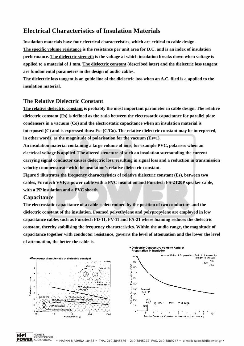
Figure 9 illustrates the frequency characteristics of relative dielectric constant (Es), between two
cables, Furutech VVF, a power cable with a PVC insulation and Furutech FS-2T20P speaker cable,
with a PP insulation and a PVC sheath.
Capacitance The electrostatic capacitance of a cable is determined by the position of two conductors and the
dielectric constant of the insulation. Foamed polyethylene and polypropylene are employed in low
capacitance cables such as Furutech FD-11, FV-11 and FA-21 where foaming reduces the dielectric
constant, thereby stabilising the frequency characteristics. Within the audio range, the magnitude of
capacitance together with conductor resistance, governs the level of attenuation and the lower the level
of attenuation, the better the cable is.

• ΜΑΡΝΗ 8 ΑΘΗΝΑ 10433 • ΤΗΛ. 210 3845676 – 210 3845272 FAX. 210 3809747 • e-mail: [email protected] •
Characteristic Impedance It is of fundamental importance for the transmission of high frequency signals such as those
from video, or digital sources, that the transmitted signals match the characteristic impedance
of the cable. The correct type of cable is a 75 ohm co-axial design and if an alternative is
employed, then the signal will be partially reflected at a connection point such as an RCA type
plug, and cannot be transmitted in a clear pattern, either the rise or the fall square wave form
is deformed or the wave form is jittered, resulting in errors which cause a degradation of the
sound quality.
Shield Cables for the purpose of interconnecting components are provided with a shield in order to
protect the signal from external noise. There are two types of shield, one for the rejection of
electrostatic ally induced noise and the other for the rejection of magnetically induced noise.
For the rejection of electrostatic noise a metal with high conductivity such as copper wire or
Aluminum foil is generally provided. Since the shield effect is in reverse proportion to the
resistance of the shield, it is necessary to reduce the resistance of the shield in order to
increases the current flow through the shield, which creates a barrier to external noise.
A ferrous material (iron, etc.) must be provided on the cable in case of shielding for the
magnetic field. But, this type of shield is not used in the audio cable because the cable becomes
thick and hard. Generally speaking, twisting of insulated conductors can have an effect to
suppress the magnetic field. However, cable engineers do not call this the magnetic shield. The
magnetic shield applies strictly to the case of providing the ferrous material.
• ΜΑΡΝΗ 8 ΑΘΗΝΑ 10433 • ΤΗΛ. 210 3845676 – 210 3845272 FAX. 210 3809747 • e-mail: [email protected] •
Appropriate Application of Interconnect Cables
Balanced and Unbalanced Interconnect Cables
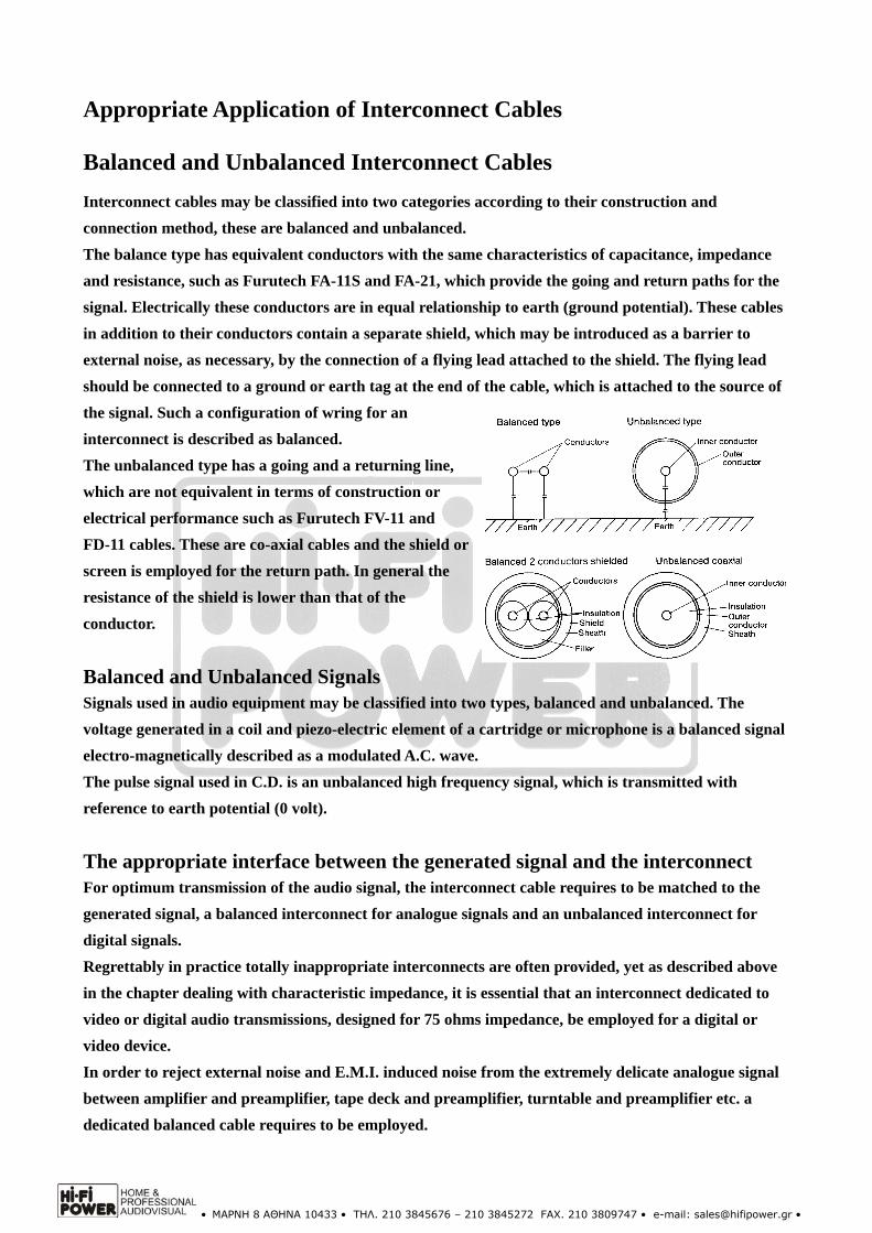
Interconnect cables may be classified into two categories according to their construction and
connection method, these are balanced and unbalanced.
The balance type has equivalent conductors with the same characteristics of capacitance, impedance
and resistance, such as Furutech FA-11S and FA-21, which provide the going and return paths for the
signal. Electrically these conductors are in equal relationship to earth (ground potential). These cables
in addition to their conductors contain a separate shield, which may be introduced as a barrier to
external noise, as necessary, by the connection of a flying lead attached to the shield. The flying lead
should be connected to a ground or earth tag at the end of the cable, which is attached to the source of
the signal. Such a configuration of wring for an
interconnect is described as balanced.
The unbalanced type has a going and a returning line,
which are not equivalent in terms of construction or
electrical performance such as Furutech FV-11 and
FD-11 cables. These are co-axial cables and the shield or
screen is employed for the return path. In general the
resistance of the shield is lower than that of the
conductor.
Balanced and Unbalanced Signals Signals used in audio equipment may be classified into two types, balanced and unbalanced. The
voltage generated in a coil and piezo-electric element of a cartridge or microphone is a balanced signal
electro-magnetically described as a modulated A.C. wave.
The pulse signal used in C.D. is an unbalanced high frequency signal, which is transmitted with
reference to earth potential (0 volt).
The appropriate interface between the generated signal and the interconnect For optimum transmission of the audio signal, the interconnect cable requires to be matched to the
generated signal, a balanced interconnect for analogue signals and an unbalanced interconnect for
digital signals.
Regrettably in practice totally inappropriate interconnects are often provided, yet as described above
in the chapter dealing with characteristic impedance, it is essential that an interconnect dedicated to
video or digital audio transmissions, designed for 75 ohms impedance, be employed for a digital or
video device.
In order to reject external noise and E.M.I. induced noise from the extremely delicate analogue signal
between amplifier and preamplifier, tape deck and preamplifier, turntable and preamplifier etc. a
dedicated balanced cable requires to be employed.
• ΜΑΡΝΗ 8 ΑΘΗΝΑ 10433 • ΤΗΛ. 210 3845676 – 210 3845272 FAX. 210 3809747 • e-mail: [email protected] •
Cable Selection
Check the cable currently in use or that, which is intended according to the following list:
Conductor material Conductor materials generally contribute to enhanced resolution; therefore check for purity
of material, grain size and crystal length, single or multiple crystals PCOCC, LC-OFC or
OFC are factors, which determine the grade of purity and therefore resolution.
Conductor construction
Where a stranded conductor is employed, particularly in speaker cables, check its cross
section is a perfect circle. Where bunch stranded are laid in the longitudinal direction, they
don’t form a perfect circle, therefore the characteristic impedance for the cable may not be
guaranteed and resultant reflections of the signal cause a deleterious sound quality.
Insulating material Frequencies fluctuate according to the efficiency of the dielectric constant of the insulation the
degree of which determines the signal transmission velocity. All Furutech cables exhibit a low
dielectric loss and a stable frequency through the audio spectrum.
Sheath
Outer sheaths require to absorb mechanical and electromagnetic ally induced vibration and
bending with relative ease, therefore they should be soft and pliable.
• ΜΑΡΝΗ 8 ΑΘΗΝΑ 10433 • ΤΗΛ. 210 3845676 – 210 3845272 FAX. 210 3809747 • e-mail: [email protected] •
Methods for Handling Audio Cables in Use
The audio cable consisting of it’s conductor, insulation and construction is a delicate,
scientifically designed product, therefore certain precautions require be taken in order that
optimum performance may be realized.
Do not wind, bundle or bind.
Do not stretch.
Do not bend excessively.
Do not place the audio cable in parallel with a power
cable.
Do not place the audio cable in parallel with ferrous
constructions.
Do not leave one end of any cable open, and do not allow
the positive and negatives paths to short circuit.
Disconnect unnecessary cables.
Do not attempt to affect a joint in cables.
Periodically clean any oxidation from contacts.
Do not use in unnecessarily long.
Improved Listening Pleasure
Appropriate cables, properly selected, dedicated to their
respective purposes and interfaces within the Hi Fi system, will transmit without deletion, all
the excitement contained in the original Hi Fi source and will make a significant and often
cost effective contribution to the quality of
listening pleasure.
Before any upgrade in the Hi Fi system is
contemplated, a simple check on the
improvements available through the existing
components via good cables and interconnects is
sincerely recommended.
Furutech appointed dealer’s will be pleased to
assist with an obligation free, home
demonstration of the very considerable sonic
improvements, which are possible.
Top Related